mODEL V-SD TECHNICAL DATA SPECIFIC APPLICATION ATTIC SPrINkLEr · SPECIFIC APPLICATION ATTIC...
12
MODEL V-SD SPECIFIC APPLICATION ATTIC SPRINKLER TECHNICAL DATA The Viking Corporation, 210 N Industrial Park Drive, Hastings MI 49058 Telephone: 269-945-9501 Technical Services: 877-384-5464 Fax: 269-818-1680 Email: [email protected] Page 1 of 12 Form No. F_043015 16.02.19 Rev 16.1 1. DESCRIPTION The Model V-SD (Single Directional) Specific Application Attic Sprinkler is designed to provide superior fire protection in combustible and non-combustible sloped attic spaces when compared to standard spray attic protection. With specific application criteria for use with Model V-BB (Back to Back) and VK696 Attic Upright Specific Application Sprinklers, Viking attic sprinklers provide an extended coverage spacing alternative to standard spray sprinklers. They make it possible to use a single line of piping at the attic peak, eliminating the need for branch lines and greatly reducing the number of required sprinklers and associated material and installation costs. Model V-SD models also have lower minimum flow and pressure requirements than competitive products. Viking Attic Sprinklers can be installed with either steel or CPVC piping (CPVC allowed on wet pipe systems only), and are available in brass or with corrosion-resistant Electroless Nickel PTFE (ENT) coatings where salt water and other corrosive elements are a consideration. They are cULus Listed with specific application guidelines for use as special sprinklers as defined by the National Fire Protection Association (NFPA), and are cULus Listed for extended coverage in combustible and non-combustible construction. The cULus Listing was achieved using full-scale fire tests within wood truss construction. The Model V-SD (Single Directional) sprinkler provides a reduced response time due to its narrow ridge spacing of 6 ft. (1,8 m) and long throw pattern (up to 40 ft. in a single direction measured horizontally) and is offered in three different slope ranges and one orifice size (K=5.6). Listed for specific pitches 4:12<7:12, 7:12<10:12 and 10:12≤12:12, and spans 40 ft. and 30 ft. 2. LISTINGS AND APPROVALS cULus Listed: Category VNIV Refer to the Approval Chart on page 3. 3. TECHNICAL DATA Specifications: Minimum Operating Pressure: See Design Criteria - UL on page 4. Rated to 175 psi (12 bar) water working pressure Factory tested hydrostatically to 500 psi (34.5 bar) Thread size: 1/2” (15 mm) NPT Nominal K-Factor: 5.6 U.S. (80.6 metric*) * Metric K-factor measurement shown is when pressure is measured in Bar. When pressure is measured in kPa, divide the metric K-factor shown by 10.0. Glass-bulb fluid temperature rated to -65 °F (-55 °C) Overall Length: 2-3/4” (69 mm) Material Standards: Frame Casting: Brass UNS-C84400 or QM Brass Deflector: Brass UNS-C23000 Bulb: Glass, nominal 3 mm diameter Belleville Spring Sealing Assembly: Nickel Alloy, coated on both sides with Teflon Tape Screw: 18-8 Stainless Steel Pip Cap and Insert Assembly: Copper UNS-C11000 and Stainless Steel UNS-S30400 Yoke: Phosphor Bronze - UNS-C51000 Deflector Screw: 316 Stainless Steel Ordering Information: (Also refer to the current Viking price list.) To order the Attic Sprinkler, add the appropriate suffix for the sprinkler finish and then the appropriate suffix for the temperature rating to the sprinkler base part number. Finish Suffix: Brass = A, ENT = JN Temperature Suffix: E = 200 °F (93.3 °C) Viking Technical Data may be found on The Viking Corporation’s Web site at http://www.vikinggroupinc.com. The Web site may include a more recent edition of this Technical Data Page. V-SD SPRINKLER (Single directional) V-SD Sprinkler 5.6K Pitch VK693 4:12 < 7:12 VK694 7:12 < 10:12 VK695 10:12 ≤ 12:12 Replaces Form F_043015 Rev. 15.3 (Revised temperature suffixes)
Transcript of mODEL V-SD TECHNICAL DATA SPECIFIC APPLICATION ATTIC SPrINkLEr · SPECIFIC APPLICATION ATTIC...
mODEL V-SD SPECIFIC APPLICATION
ATTIC SPrINkLErTECHNICAL DATA
The Viking Corporation, 210 N Industrial Park Drive, Hastings mI 49058Telephone: 269-945-9501 Technical Services: 877-384-5464 Fax: 269-818-1680 Email: [email protected]
Page 1 of 12
Form No. F_043015 16.02.19 Rev 16.1
1. DESCrIPTIONThe Model V-SD (Single Directional) Specific Application Attic Sprinkler is designed to provide superior fire protection in combustible and non-combustible sloped attic spaces when compared to standard spray attic protection. With specific application criteria for use with Model V-BB (Back to Back) and VK696 Attic Upright Specific Application Sprinklers, Viking attic sprinklers provide an extended coverage spacing alternative to standard spray sprinklers. They make it possible to use a single line of piping at the attic peak, eliminating the need for branch lines and greatly reducing the number of required sprinklers and associated material and installation costs. Model V-SD models also have lower minimum flow and pressure requirements than competitive products. Viking Attic Sprinklers can be installed with either steel or CPVC piping (CPVC allowed on wet pipe systems only), and are available in brass or with corrosion-resistant Electroless Nickel PTFE (ENT) coatings where salt water and other corrosive elements are a consideration. They are cULus Listed with specific application guidelines for use as special sprinklers as defined by the National Fire Protection Association (NFPA), and are cULus Listed for extended coverage in combustible and non-combustible construction. The cULus Listing was achieved using full-scale fire tests within wood truss construction.The Model V-SD (Single Directional) sprinkler provides a reduced response time due to its narrow ridge spacing of 6 ft. (1,8 m) and long throw pattern (up to 40 ft. in a single direction measured horizontally) and is offered in three different slope ranges and one orifice size (K=5.6). Listed for specific pitches 4:12<7:12, 7:12<10:12 and 10:12≤12:12, and spans 40 ft. and 30 ft.
2. LISTINGS AND APPrOVALScULus Listed: Category VNIV
Refer to the Approval Chart on page 3.
3. TECHNICAL DATASpecifications:Minimum Operating Pressure: See Design Criteria - UL on page 4.Rated to 175 psi (12 bar) water working pressureFactory tested hydrostatically to 500 psi (34.5 bar)Thread size: 1/2” (15 mm) NPTNominal K-Factor: 5.6 U.S. (80.6 metric*)
* Metric K-factor measurement shown is when pressure is measured in Bar. When pressure is measured in kPa, divide the metric K-factor shown by 10.0.Glass-bulb fluid temperature rated to -65 °F (-55 °C)Overall Length: 2-3/4” (69 mm)material Standards:Frame Casting: Brass UNS-C84400 or QM BrassDeflector: Brass UNS-C23000Bulb: Glass, nominal 3 mm diameterBelleville Spring Sealing Assembly: Nickel Alloy, coated on both sides with Teflon TapeScrew: 18-8 Stainless SteelPip Cap and Insert Assembly: Copper UNS-C11000 and Stainless Steel UNS-S30400Yoke: Phosphor Bronze - UNS-C51000Deflector Screw: 316 Stainless SteelOrdering Information: (Also refer to the current Viking price list.)To order the Attic Sprinkler, add the appropriate suffix for the sprinkler finish and then the appropriate suffix for the temperature
rating to the sprinkler base part number.Finish Suffix: Brass = A, ENT = JNTemperature Suffix: E = 200 °F (93.3 °C)
Viking Technical Data may be found on The Viking Corporation’s Web site at
http://www.vikinggroupinc.com.The Web site may include a more recent
edition of this Technical Data Page.
V-SD SPrINkLEr(Single directional)
V-SD Sprinkler5.6k Pitch
VK693 4:12 < 7:12
VK694 7:12 < 10:12
VK695 10:12 ≤ 12:12
Replaces Form F_043015 Rev. 15.3 (Revised temperature suffixes)
mODEL V-SD SPECIFIC APPLICATION
ATTIC SPrINkLErTECHNICAL DATA
The Viking Corporation, 210 N Industrial Park Drive, Hastings mI 49058Telephone: 269-945-9501 Technical Services: 877-384-5464 Fax: 269-818-1680 Email: [email protected]
Page 2 of 12
Form No. F_043015 16.02.19 Rev 16.1
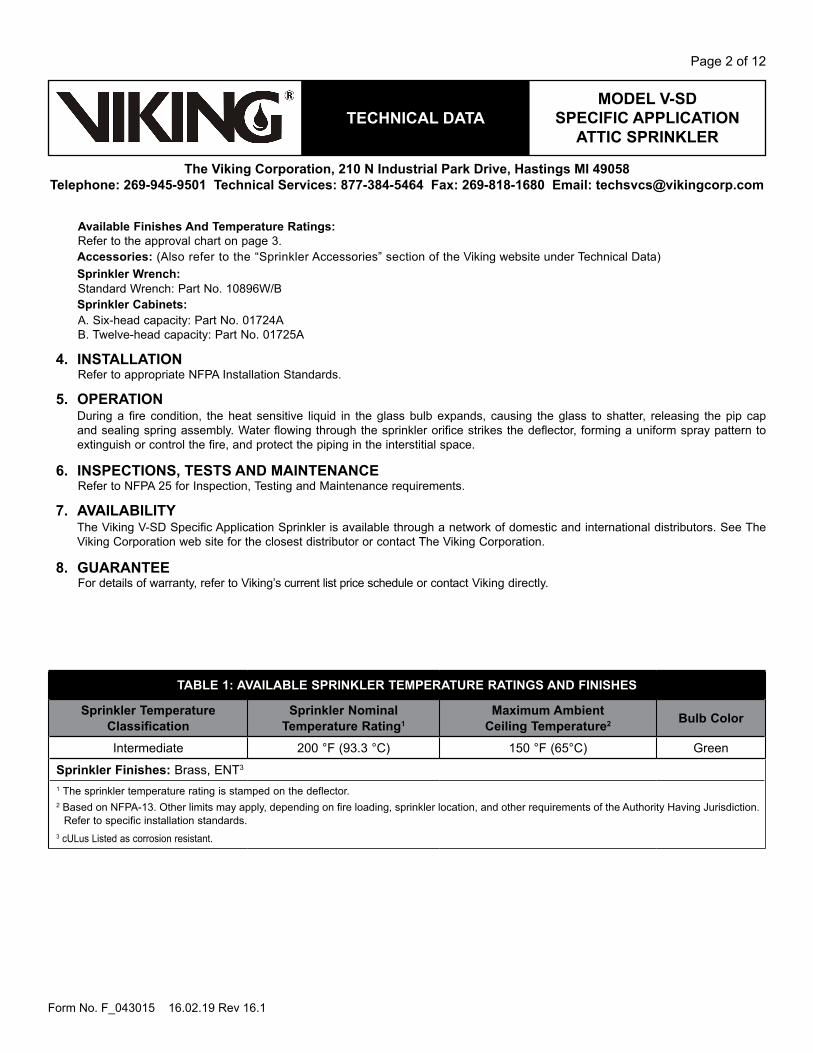
Available Finishes And Temperature ratings: Refer to the approval chart on page 3.Accessories: (Also refer to the “Sprinkler Accessories” section of the Viking website under Technical Data)Sprinkler Wrench:Standard Wrench: Part No. 10896W/BSprinkler Cabinets:A. Six-head capacity: Part No. 01724AB. Twelve-head capacity: Part No. 01725A
4. INSTALLATIONRefer to appropriate NFPA Installation Standards.
5. OPErATIONDuring a fire condition, the heat sensitive liquid in the glass bulb expands, causing the glass to shatter, releasing the pip cap and sealing spring assembly. Water flowing through the sprinkler orifice strikes the deflector, forming a uniform spray pattern to extinguish or control the fire, and protect the piping in the interstitial space.
6. INSPECTIONS, TESTS AND mAINTENANCERefer to NFPA 25 for Inspection, Testing and Maintenance requirements.
7. AVAILAbILITyThe Viking V-SD Specific Application Sprinkler is available through a network of domestic and international distributors. See The Viking Corporation web site for the closest distributor or contact The Viking Corporation.
8. GUArANTEEFor details of warranty, refer to Viking’s current list price schedule or contact Viking directly.
TAbLE 1: AVAILAbLE SPrINkLEr TEmPErATUrE rATINGS AND FINISHES
Sprinkler Temperature Classification
Sprinkler Nominal Temperature rating1
maximum Ambient Ceiling Temperature2 bulb Color
Intermediate 200 °F (93.3 °C) 150 °F (65°C) Green
Sprinkler Finishes: Brass, ENT3
1 The sprinkler temperature rating is stamped on the deflector. 2 Based on NFPA-13. Other limits may apply, depending on fire loading, sprinkler location, and other requirements of the Authority Having Jurisdiction.
Refer to specific installation standards.3 cULus Listed as corrosion resistant.
mODEL V-SD SPECIFIC APPLICATION
ATTIC SPrINkLErTECHNICAL DATA
The Viking Corporation, 210 N Industrial Park Drive, Hastings mI 49058Telephone: 269-945-9501 Technical Services: 877-384-5464 Fax: 269-818-1680 Email: [email protected]
Page 3 of 12
Form No. F_043015 16.02.19 Rev 16.1
Figure 1: Standard Sprinkler Wrench 10896W/b
Wrench Flat
ProtectiveSprinkler
Clip
Figure 2: Sprinkler Dimensions
2-3/4”(69,8 mm)
1/2”(15 mm) NPT
1-1/8”(27,9 mm)
1-3/4”(44,4 mm)
7/16 “ (11,1 mm)Nominal PipeEngagement
Approval ChartViking V-SD Specific Application Sprinkler
For Combustible and Non-Combustible Sloped Attic Spaces
Part Number1 SIN maximum
PressureThread Size Nominal
k-Factor Overall Length Listings and Approvals3
NPT bSP U.S. metric2 Inches mm cULus4 Fm LPCb 19578 VK693 175 psi 1/2” 15 mm 5.6 80.6 2-3/4 69 A1, A2 -- -- -- --19799 VK694 175 psi 1/2” 15 mm 5.6 80.6 2-3/4 69 A1, A2 -- -- -- --19759 VK695 175 psi 1/2” 15 mm 5.6 80.6 2-3/4 69 A1, A2 -- -- -- --
Approved Temperature ratingA - 200 °F (93.3 °C)
Approved Finish1 - Brass, 2 - ENT5
1 Also refer to Viking’s current price schedule.2 Metric K-factor measurement shown is when pressure is measured in Bar. When pressure is measured in kPa, divide the metric K-factor shown by 10.0.3 This table shows the listings and approvals available at the time of printing. Other approvals may be in process.4 Listed by Underwriters Laboratories Inc. for use in the United States and Canada.5 cULus Listed as corrosion resistant.
mODEL V-SD SPECIFIC APPLICATION
ATTIC SPrINkLErTECHNICAL DATA
The Viking Corporation, 210 N Industrial Park Drive, Hastings mI 49058Telephone: 269-945-9501 Technical Services: 877-384-5464 Fax: 269-818-1680 Email: [email protected]
Page 4 of 12
Form No. F_043015 16.02.19 Rev 16.1
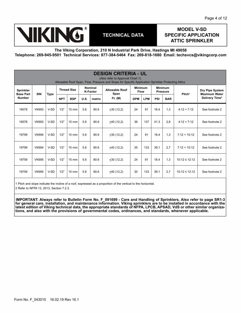
DESIGN CrITErIA - UL(Also refer to Approval Chart 1)
Allowable Roof Span, Flow, Pressure and Slope for Specific Application Sprinkler Protecting Attics
Sprinkler base Part Number
SIN TypeThread Size Nominal
k-Factor Allowable roof Span
Ft. (m)
minimum Flow
minimum Pressure
Pitch1Dry Pipe System maximum Water Delivery Time2
NPT bSP U.S. metric GPm LPm PSI bAr
19578 VK693 V-SD 1/2” 15 mm 5.6 80.6 <30 (12,2) 24 91 18.4 1,3 4:12 < 7:12 See footnote 2
19578 VK693 V-SD 1/2” 15 mm 5.6 80.6 <40 (12,2) 36 137 41.3 2,8 4:12 < 7:12 See footnote 2
19799 VK694 V-SD 1/2” 15 mm 5.6 80.6 <30 (12,2) 24 91 18.4 1,3 7:12 < 10:12 See footnote 2
19799 VK694 V-SD 1/2” 15 mm 5.6 80.6 <40 (12,2) 35 133 39.1 2,7 7:12 < 10:12 See footnote 2
19759 VK695 V-SD 1/2” 15 mm 5.6 80.6 <30 (12,2) 24 91 18.4 1,3 10:12 ≤ 12:12 See footnote 2
19759 VK695 V-SD 1/2” 15 mm 5.6 80.6 <40 (12,2) 35 133 39.1 2,7 10:12 ≤ 12:12 See footnote 2
1 Pitch and slope indicate the incline of a roof, expressed as a proportion of the vertical to the horizontal.2 Refer to NFPA 13, 2013, Section 7.2.3.
ImPOrTANT: Always refer to bulletin Form No. F_091699 - Care and Handling of Sprinklers. Also refer to page Sr1-3 for general care, installation, and maintenance information. Viking sprinklers are to be installed in accordance with the latest edition of Viking technical data, the appropriate standards of NFPA, LPCb, APSAD, VdS or other similar organiza-tions, and also with the provisions of governmental codes, ordinances, and standards, whenever applicable.
mODEL V-SD SPECIFIC APPLICATION
ATTIC SPrINkLErTECHNICAL DATA
The Viking Corporation, 210 N Industrial Park Drive, Hastings mI 49058Telephone: 269-945-9501 Technical Services: 877-384-5464 Fax: 269-818-1680 Email: [email protected]
Page 5 of 12
Form No. F_043015 16.02.19 Rev 16.1
ADDITIONAL DESIGN CrITErIA - UL Chart 2(Also refer to DESIGN CRITERA Chart 1)
Allowable roof span, flow, pressure and slope for attic protection using Viking V-SD Sprinklers
Design Criteria: Flow and Pressures refer to Design Chart 1.System Type: Wet systems and dry systems.Piping Types: Steel (wet and dry) CPVC (wet systems only).Occupancy Classification: Light hazard only.
Viking V-SD Sprinkler Spacing
maximum Coverage Area: 339 ft2 (31.5 m2) as measured along the slope.Coverage area is determined by the maximum distance thrown measured along the slope, multiplied by the distance along the branch line.Along the branch Line:Minimum Spacing: 4’-0” (1,22 m) between V-SD’s and from V-BB’s. 7’-0” (2,13 m) from Viking Attic Uprights. 6’-0” (1,83 m) from Standard Spray Sprinklers.Maximum Spacing: 6’-0” (1,83 m) between V-SD’s and from V-BB’s.measured Down the Slope:Minimum Spacing: 26’-0” (7,92 m) from Viking Attic Uprights and Standard Spray Sprinklers.Deflector Position below Peak, ridge, or Deck:For all roof pitches as per the listing from 4:12 – 12:12 the maximum deflector distance down is 22” (559 mm), and the minimum deflector distance down is 16” (406 mm).Deflector Position above Scissor Truss:For all roof pitches as per the listing from 4:12 – 12:12 the minimum distance above a Scissor Truss is 18” (457 mm).maximum distance from center line of the ridge: 6” (152 mm) on either side of the center line.minimum distance from Truss: 6” (152 mm) from nearest edge of the truss.Distance from Shear Wall: 4” – 6” (102 - 152 mm) from face of wall.Distance from Draft Curtain: 4” – 6” (102 - 152 mm) from face of draft curtain and a minimum of 8” above the bottom.Draft Curtains: Where used to allow Attic Sprinkler installation shall be constructed to contain heat, may be constructed of ½” plywood.Asymmetrical Slopes: Refer to Figure 4.
Continues on next page.
mODEL V-SD SPECIFIC APPLICATION
ATTIC SPrINkLErTECHNICAL DATA
The Viking Corporation, 210 N Industrial Park Drive, Hastings mI 49058Telephone: 269-945-9501 Technical Services: 877-384-5464 Fax: 269-818-1680 Email: [email protected]
Page 6 of 12
Form No. F_043015 16.02.19 Rev 16.1
Continued from previous page.
Use of UL Listed CPVC blazemaster Piping (Wet Systems Only):Can be used to supply the sprinklers protecting the floor below the combustible concealed space when covered with 6” (152 mm) of non-combustible insulation over the horizontal or vertical piping, and extending 12” (304 mm) on both sides of the center line of the piping. If the piping is located in the joist, the width of the joist channel must be entirely covered to 6” (152 mm) above the top of the piping. The area above the piping must be protected with the Viking Model V-BB’s, V-SD’s, or the Attic Upright Sprinklers. Listed CPVC Blazemaster piping may also be used exposed to feed wet systems using Viking V-SD sprinklers in accordance with the following requirements, and in accordance with Figure 5:• Risers are vertical and protected by V-SD or V-BB sprinklers located a maximum of 12” away from the riser centerline.• Model V-SD or V-BB sprinklers are mounted directly to the branchline.• Model V-SD or V-BB sprinklers are installed on arm-overs a maximum of 6” (152 mm) laterally from the center line of the branch line.• Model V-SD or V-BB sprinklers are installed on Vertical Sprigs attached to the branchline.• Model V-SD or V-BB sprinklers are installed on angled sprigs a maximum of 6” (152 mm) laterally from the centerline of the branchline.• Installed with a minimum lateral distance of 18” (457 mm) from any device that produces and releases heat, i.e Attic furnace, Kitchen
or Bathroom Exhaust fan, Flue Vents, Heat Lamps, and other such devices.
Insulation requirements are provided solely for Fire Protection purposes and not for freeze protection.
Non-combustible insulation being used needs to be verified for chemical compatibility with the CPVC piping at www.lubrizol.com
Obstruction Criteria:Refer to Figures 6—12Refer to Sections 8.8.5.2.1.3 and 8.8.5.2.1.7 of NFPA 13, 2013 for requirements if installed on greater than 2-1/2” diameter piping.Hydraulic requirements:Viking V-SD Sprinklers must be calculated in accordance with the following figures and guidelines.The design area shall include the most hydraulically demanding sprinklers, and in certain cases may require more than one set of calculations to verify the systems design.The following figures cover Hydraulic Requirements for Viking V-SD Sprinklers only, and when installed with Standard Spray Sprinklers.For areas using Viking V-BB Sprinklers and/or Viking Attic Upright Sprinklers refer to the applicable data sheets.refer to Figures:Figure 13 V-SD SprinklersFigure 14 V-SD Sprinklers & Attic Upright or Standard Spray Sprinklers at the ridge.Figure 15 V-SD Sprinklers & Attic Upright or Standard Spray Sprinklers by compartmentalization.
mODEL V-SD SPECIFIC APPLICATION
ATTIC SPrINkLErTECHNICAL DATA
The Viking Corporation, 210 N Industrial Park Drive, Hastings mI 49058Telephone: 269-945-9501 Technical Services: 877-384-5464 Fax: 269-818-1680 Email: [email protected]
Page 7 of 12
Form No. F_043015 16.02.19 Rev 16.1
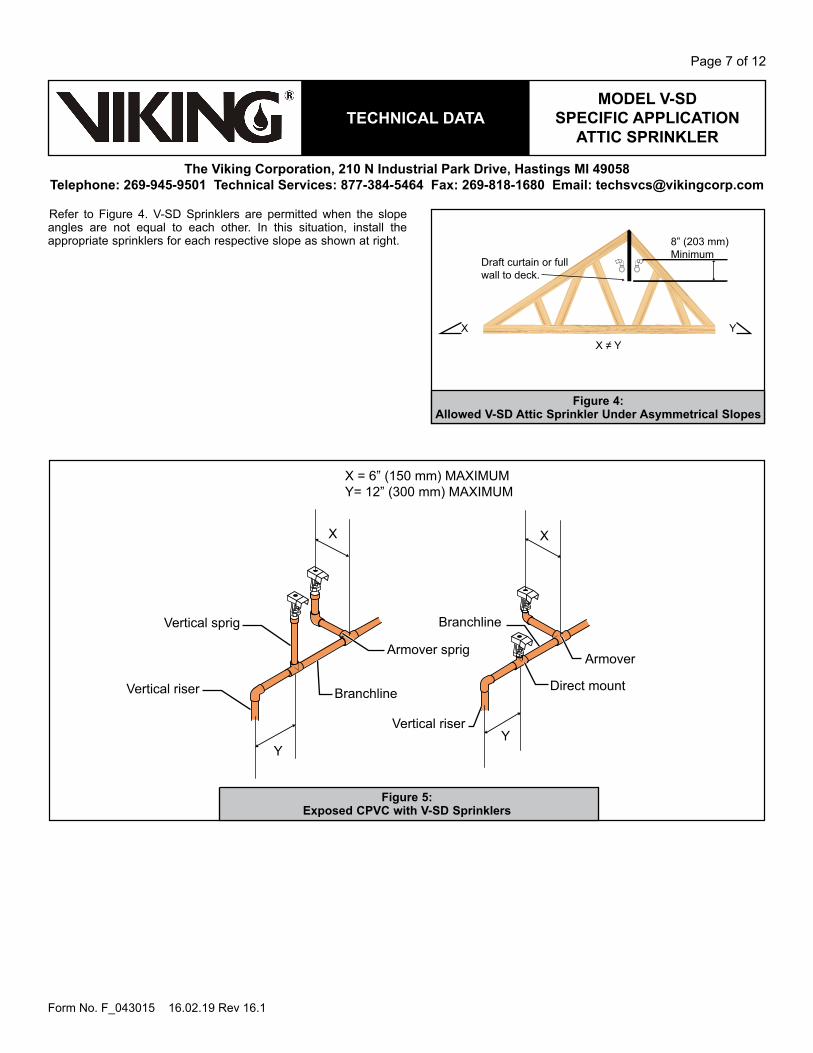
Figure 4: Allowed V-SD Attic Sprinkler Under Asymmetrical Slopes
8” (203 mm) Minimum
Draft curtain or full wall to deck.
XX ≠ Y
Y
Refer to Figure 4. V-SD Sprinklers are permitted when the slope angles are not equal to each other. In this situation, install the appropriate sprinklers for each respective slope as shown at right.
Vertical riser
Vertical riser
Vertical sprig
Branchline
Armover sprig
X = 6” (150 mm) MAXIMUMY= 12” (300 mm) MAXIMUM
Direct mount
Armover
Branchline
X X
YY
Figure 5: Exposed CPVC with V-SD Sprinklers
mODEL V-SD SPECIFIC APPLICATION
ATTIC SPrINkLErTECHNICAL DATA
The Viking Corporation, 210 N Industrial Park Drive, Hastings mI 49058Telephone: 269-945-9501 Technical Services: 877-384-5464 Fax: 269-818-1680 Email: [email protected]
Page 8 of 12
Form No. F_043015 16.02.19 Rev 16.1
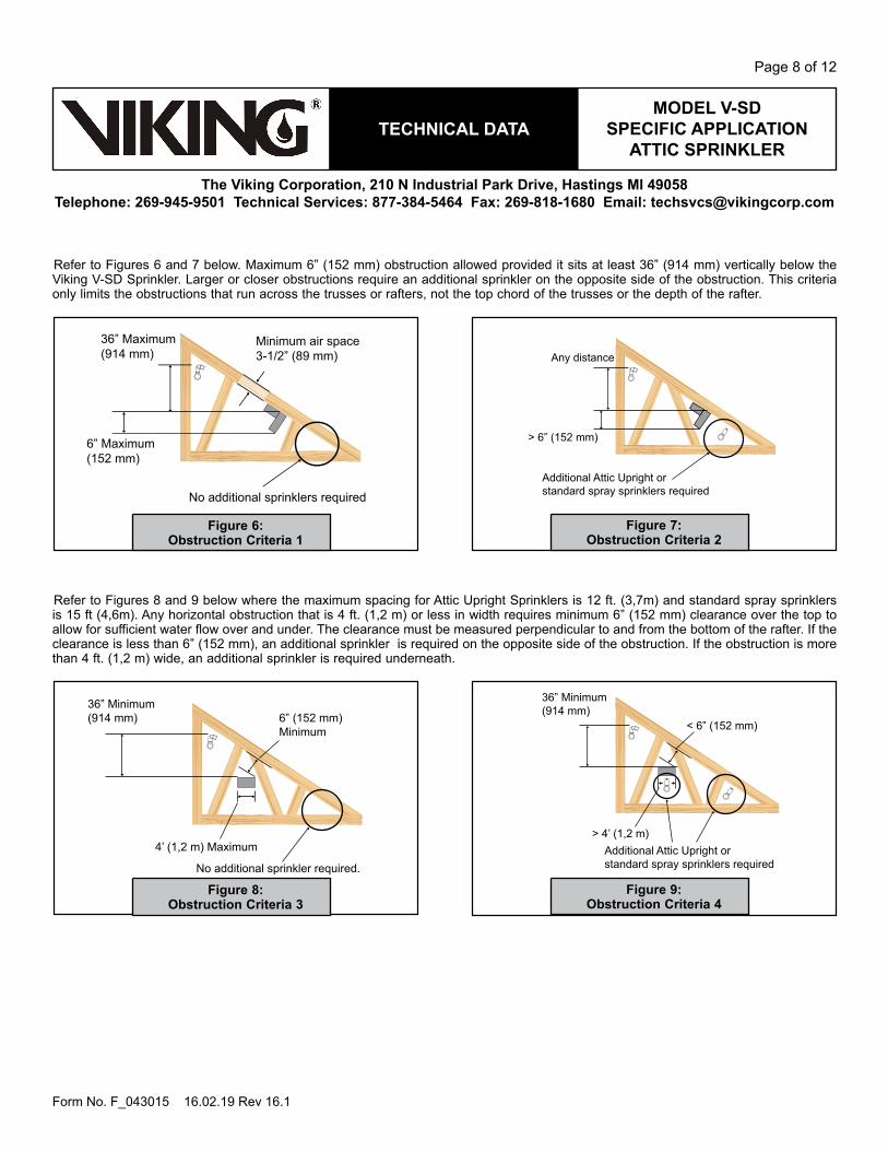
Figure 6: Obstruction Criteria 1
Figure 8: Obstruction Criteria 3
Figure 7: Obstruction Criteria 2
Figure 9: Obstruction Criteria 4
6” Maximum(152 mm)
36” Maximum(914 mm)
No additional sprinklers required
Minimum air space 3-1/2” (89 mm)
6” (152 mm)Minimum
36” Minimum(914 mm)
No additional sprinkler required.
4’ (1,2 m) Maximum
Refer to Figures 6 and 7 below. Maximum 6” (152 mm) obstruction allowed provided it sits at least 36” (914 mm) vertically below the Viking V-SD Sprinkler. Larger or closer obstructions require an additional sprinkler on the opposite side of the obstruction. This criteria only limits the obstructions that run across the trusses or rafters, not the top chord of the trusses or the depth of the rafter.
Refer to Figures 8 and 9 below where the maximum spacing for Attic Upright Sprinklers is 12 ft. (3,7m) and standard spray sprinklers is 15 ft (4,6m). Any horizontal obstruction that is 4 ft. (1,2 m) or less in width requires minimum 6” (152 mm) clearance over the top to allow for sufficient water flow over and under. The clearance must be measured perpendicular to and from the bottom of the rafter. If the clearance is less than 6” (152 mm), an additional sprinkler is required on the opposite side of the obstruction. If the obstruction is more than 4 ft. (1,2 m) wide, an additional sprinkler is required underneath.
Any distance
> 6” (152 mm)
Additional Attic Upright or standard spray sprinklers required
< 6” (152 mm)
36” Minimum(914 mm)
> 4’ (1,2 m)Additional Attic Upright or standard spray sprinklers required
mODEL V-SD SPECIFIC APPLICATION
ATTIC SPrINkLErTECHNICAL DATA
The Viking Corporation, 210 N Industrial Park Drive, Hastings mI 49058Telephone: 269-945-9501 Technical Services: 877-384-5464 Fax: 269-818-1680 Email: [email protected]
Page 9 of 12
Form No. F_043015 16.02.19 Rev 16.1
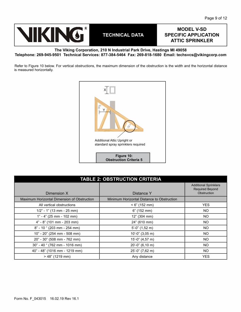
Figure 10: Obstruction Criteria 5
Additional Attic Upright or standard spray sprinklers required
Y
X
Refer to Figure 10 below. For vertical obstructions, the maximum dimension of the obstruction is the width and the horizontal distance is measured horizontally.
TAbLE 2: ObSTrUCTION CrITErIA
Dimension X Distance Y
Additional Sprinklers Required Beyond
Obstruction
Maximum Horizontal Dimension of Obstruction Minimum Horizontal Distance to ObstructionAll vertical obstructions < 6” (152 mm) YES
1/2” - 1” (13 mm - 25 mm) 6” (152 mm) NO1” - 4” (25 mm - 102 mm) 12” (304 mm) NO4” - 8” (101 mm - 203 mm) 24” (610 mm) NO
8” - 10 “ (203 mm - 254 mm) 5’-0” (1,52 m) NO10” - 20” (254 mm - 508 mm) 10’-0” (3,05 m) NO20” - 30” (508 mm - 762 mm) 15’-0” (4,57 m) NO
30” - 40 “ (762 mm - 1016 mm) 20’-0” (6,10 m) NO40” - 48” (1016 mm - 1219 mm) 25’-0” (7,62 m) NO
> 48” (1219 mm) Any distance YES
mODEL V-SD SPECIFIC APPLICATION
ATTIC SPrINkLErTECHNICAL DATA
The Viking Corporation, 210 N Industrial Park Drive, Hastings mI 49058Telephone: 269-945-9501 Technical Services: 877-384-5464 Fax: 269-818-1680 Email: [email protected]
Page 10 of 12
Form No. F_043015 16.02.19 Rev 16.1
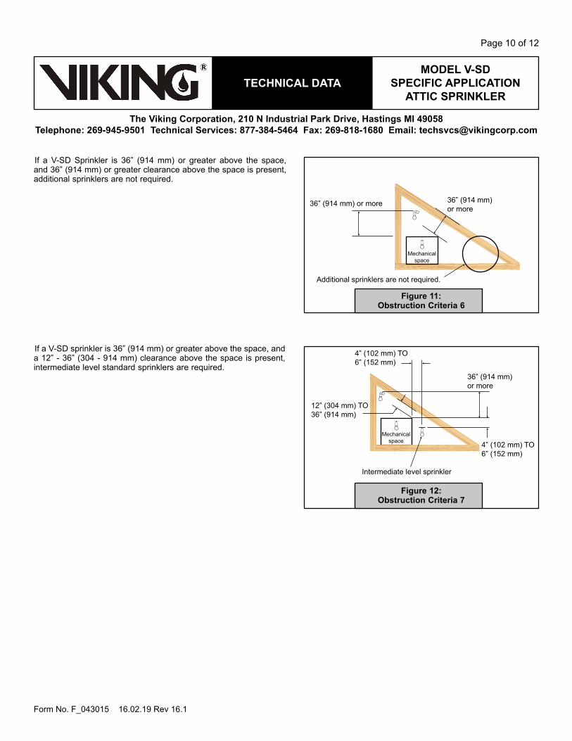
Figure 11: Obstruction Criteria 6
Figure 12: Obstruction Criteria 7
36” (914 mm) or more
Mechanical space
36” (914 mm) or more
Additional sprinklers are not required.
36” (914 mm) or more
4” (102 mm) TO6” (152 mm)
4” (102 mm) TO6” (152 mm)
Mechanical space
Intermediate level sprinkler
12” (304 mm) TO36” (914 mm)
If a V-SD Sprinkler is 36” (914 mm) or greater above the space, and 36” (914 mm) or greater clearance above the space is present, additional sprinklers are not required.
If a V-SD sprinkler is 36” (914 mm) or greater above the space, and a 12” - 36” (304 - 914 mm) clearance above the space is present, intermediate level standard sprinklers are required.
mODEL V-SD SPECIFIC APPLICATION
ATTIC SPrINkLErTECHNICAL DATA
The Viking Corporation, 210 N Industrial Park Drive, Hastings mI 49058Telephone: 269-945-9501 Technical Services: 877-384-5464 Fax: 269-818-1680 Email: [email protected]
Page 11 of 12
Form No. F_043015 16.02.19 Rev 16.1
60’ (
18,3
m) r
oof s
pan
60’ (
18,3
m) r
oof s
pan
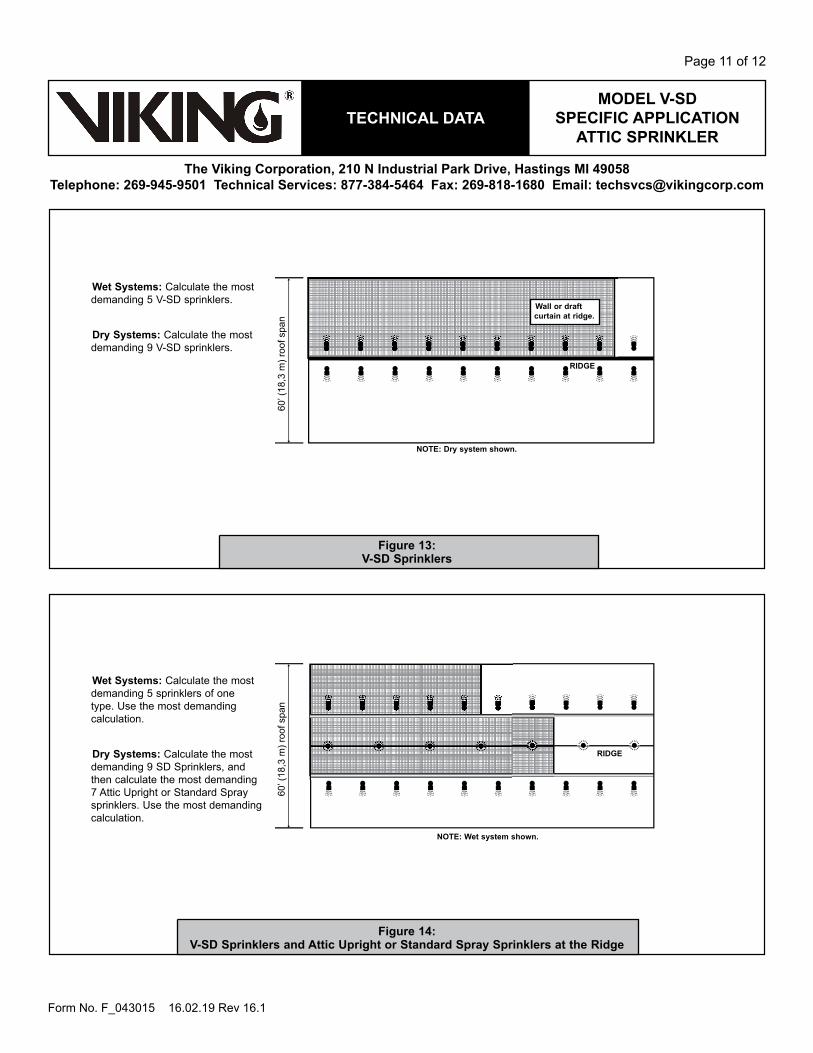
Figure 13: V-SD Sprinklers
Figure 14: V-SD Sprinklers and Attic Upright or Standard Spray Sprinklers at the ridge
Wet Systems: Calculate the most demanding 5 V-SD sprinklers.
Dry Systems: Calculate the most demanding 9 V-SD sprinklers.
Wet Systems: Calculate the most demanding 5 sprinklers of one type. Use the most demanding calculation.
Dry Systems: Calculate the most demanding 9 SD Sprinklers, and then calculate the most demanding 7 Attic Upright or Standard Spray sprinklers. Use the most demanding calculation.
rIDGE
rIDGE
Wall or draft curtain at ridge.
NOTE: Dry system shown.
NOTE: Wet system shown.
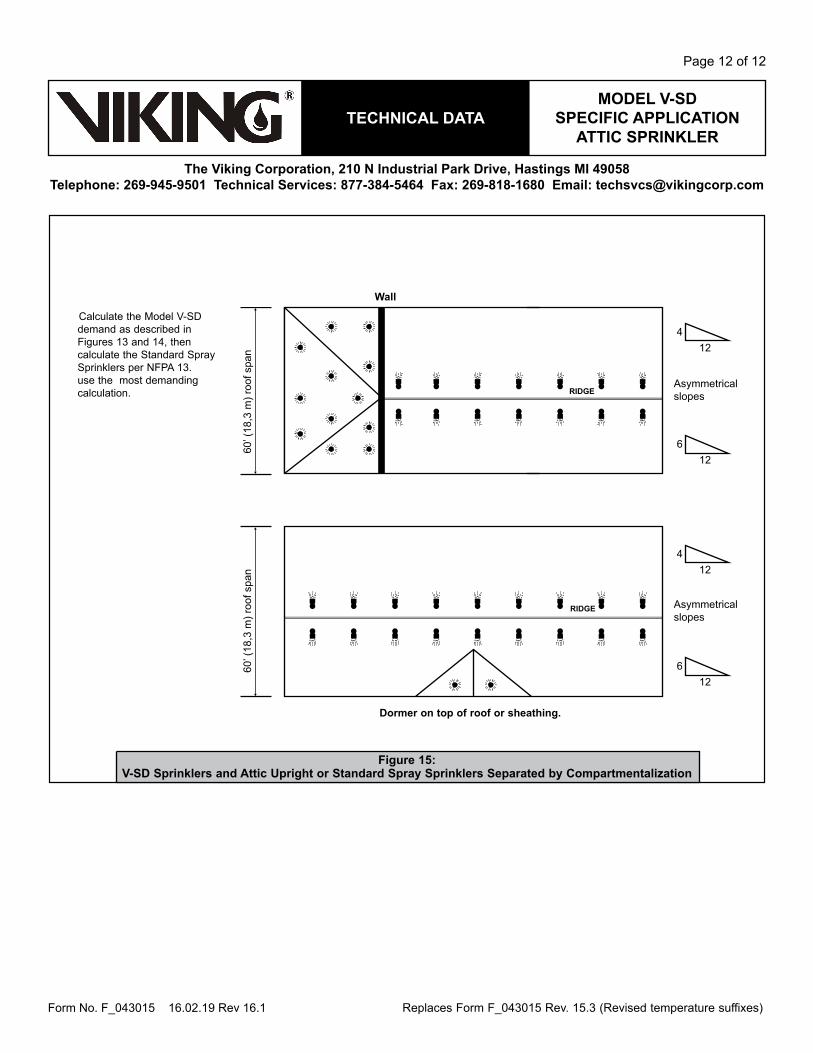
mODEL V-SD SPECIFIC APPLICATION
ATTIC SPrINkLErTECHNICAL DATA
The Viking Corporation, 210 N Industrial Park Drive, Hastings mI 49058Telephone: 269-945-9501 Technical Services: 877-384-5464 Fax: 269-818-1680 Email: [email protected]
Page 12 of 12
Form No. F_043015 16.02.19 Rev 16.1
Figure 15: V-SD Sprinklers and Attic Upright or Standard Spray Sprinklers Separated by Compartmentalization
Calculate the Model V-SD demand as described in Figures 13 and 14, then calculate the Standard Spray Sprinklers per NFPA 13. use the most demanding calculation.
Dormer on top of roof or sheathing.
Wall
rIDGE
rIDGE
60’ (
18,3
m) r
oof s
pan
60’ (
18,3
m) r
oof s
pan 12
4
126
124
126
Asymmetrical slopes
Asymmetrical slopes
Replaces Form F_043015 Rev. 15.3 (Revised temperature suffixes)