Model PS-15 Power Supply
13
Model PS-15 Power Supply 9350678600 Rev H 11/2006
Transcript of Model PS-15 Power Supply
Model PS-15Power Supply
9350678600 Rev H 11/2006
PROPRIETARY NOTICE
The product information and design disclosed herein were originated by and are the property of Telex Communications, Inc. Telex reserves all patent, proprietary design, manufacturing, reproduction, use and sales rights thereto, and to any article disclosed therein, except to the extent rights are expressly granted to others.
COPYRIGHT NOTICE
Copyright 2006 by Telex Communications, Inc. All rights reserved. Reproduction, in whole or in part, without prior written permission from Telex is prohibited.
WARRANTY NOTICE
See the enclosed warranty card for further details.
CUSTOMER SUPPORT
Technical questions should be directed to:
Customer Service DepartmentRTS/Telex Communications, Inc.12000 Portland Avenue SouthBurnsville, MN 55337 USATelephone: 800-392-3497Fax: 800-323-0498
RETURN SHIPPING INSTRUCTIONS
Customer Service DepartmentTelex Communications, Inc. (Lincoln, NE)Telephone: 402-467-5321Fax: 402-467-3279Factory Service: 800-553-5992
Please include a note in the box which supplies the company name, address, phone number, a person to contact regarding the repair, the type and quantity of equipment, a description of the problem and the serial number(s).
SHIPPING TO THE MANUFACTURER
All shipments of product should be made via UPS Ground, prepaid (you may request from Factory Service a different shipment method). Any shipment upgrades will be paid by the customer. The equipment should be shipped in the original packing carton. If the original carton is not available, use any suitable container that is rigid and of adequate size. If a substitute container is used, the equipment should be wrapped in paper and surrounded with at least four (4) inches of excelsior or similar shock-absorbing material. All shipments must be sent to the following address and must include the Proof of Purchase for warranty repair. Upon completion of any repair the equipment will be returned via United Parcel Service or specified shipper, collect.
Factory Service DepartmentTelex Communications, Inc.8601 East Cornhusker Hwy.Lincoln, NE 68507 U.S.A.Attn: Service
This package should include the following:

TABLE OF CONTENTS
PROPRIETARYNOTICE 2
COPYRIGHTNOTICE , 2
PATENTNOTICE 2
UNPACKINGANDINSPECTION 2
WARRANTYThWORMATION.. 2
RETURNSHWPINGINSTRUCTIONS 2
SECTION 1: DESCRIPTION & SPECIFICATIONS 4
1.1 DESCRIPTION. 4
1.2MODELPS15SPECIFICATIONS ,... 4
SECTION 2: INST ALLA TION 6
2.1MECHANICALINSTALLATION 5
2.2 OUTPUTS. 5
2.3POWERANDINPUTPOWERSELECTION 5
2.4ELEC1RICALPERFORMANCEANDLOADING 5
2.5TANDEMOPERATION 5
2.6AUDIOOUTPUT/INPUT 5
2.7STANDARDUSERSTATIONCONNECTIONS 9
SECTION 3: OPERA TION , 7
SECTION7:DIAGRAMS 8
Page 3

SECTION I:DESCRIPTION AND SPEClFICA TIONS
1.2 MODEL PSIS SPECIFICATIONS
1.1 DESCRIJYrIONOutputs
One powered channel, CHI, (audio + DC + 200ohm/400 ohm 10% termination}, and one passive chan-nel' CH2, (audio + 200/400 ohm 20% termination}.The Model PS 15 Power Supply is designed to work within
the TW Intercom System. The PS 15 is suitable for small tomedium sized TW Intercom Systems. Output Voltage
No Load
Full Load
32.0 +2.0. -1.0 volts24.0 volts. nominalThe unit is self-contained and features two-channel opern-
tion: one "wet" channel with 24 to 32 volts DC and one"dry" channel without voltage potential. Each channelprovides an audio termination impedance of 200 or 400ohms (switch selectable).
Output Impedance200 or 400 ohms 20%. switchable. On poweredchannel. 200 ohms. nominal. is maintained from 18.0to 33.0 volts.
This power supply allows speech signals and DC to exist onthe same wire (Channel I). The power supply's outputs areprotected against short circuit conditions with recoverybeing automatic and instantaneous.
Output Current
S13nd'Jfd Option
*p Option (234 V)
#D Option (IOOV)
Fault Current
.9 ampere at 21/+4-2 volts. DC
.9 ampere at 21/+4-2 volts. DC
.8 ampere at 21/+4-2 volts. DC1.5 amperes at 0.0 volts. DCA single PS 15 Power Supply can power 6 to 30 user stations
(depending on model and combination -see specifications).Signal Level
Nominal
Maximum
If still more user stations are needed, two PS 15 PowerSupplies can be coupled together to double the poweringcapability: a 1/4-inch 3-circuit phone jack is available oneach power supply for this purpose. This connector can alsobe used as a one-way output port when monitoring orrecording the intercom audio signals.
2.0 volts peak to peak5.0 volts peak to peak
Frequency Response100 hertz to 20 kilohertz +1, -5 dB
When two PS15 supplies are combined. toggling a rearpmlel switch on each supply will keep the audio levelconstallt. Two PS 15. s can power as many stations as a PS31(with DC load evenly distributed between the two supplies).Since the PS31 supplies more voltage than the PS15 underfull load. the PS31 is better suited to power a large systemspread over a large area.
Signal-to-Noise RatioReference 2.0 volts. peak to peak: 60 dB nomina]
Mains VoltageStandard
*POption#D Option
117 volts :t10%. 50 -60 hertz234 volts :t10% 50-60 hertz100 volts +10%. -5%.50-60 hertz
There are two XLR-type 3-pin male connectors mounted onthe rear panel for output interconnection to the user stations.
Mains Amperes0.40 at 117 volts :t10%, 50-60 hertz0.20 at 234 volts :t10%, 50-60 hertz0.40 at 100 volts +10%, -5%,50-60 hertz
The PS 15 has been designed to meet UL 1419 specifications(professional Audio and Video Equipment). Environmental
TemperatureOperatingStoralJeo
Humidity
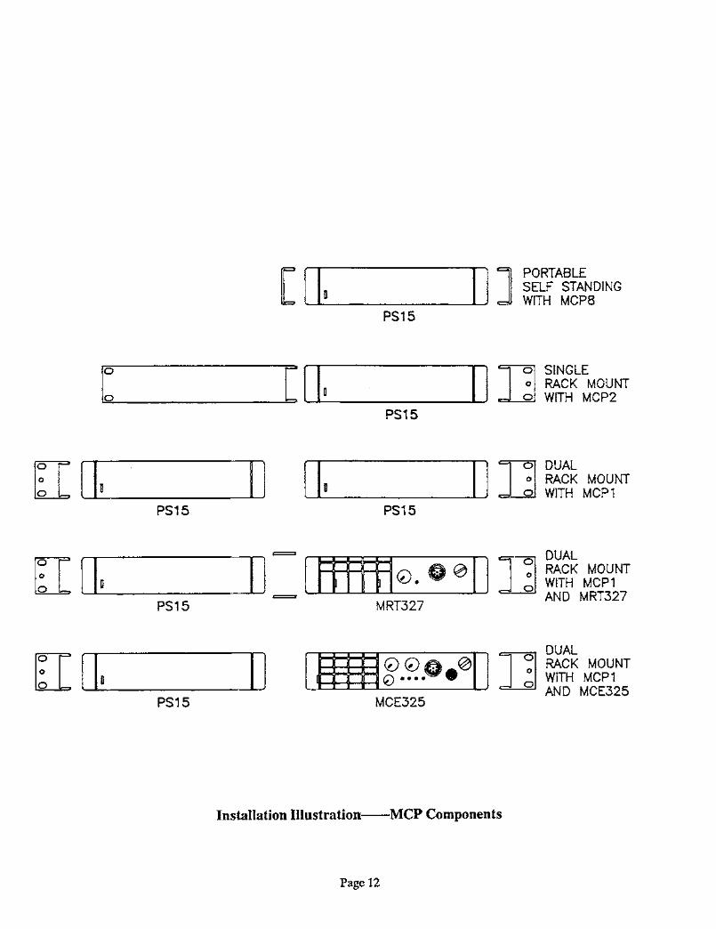
The PSIS Power Supply may be used in portable applica-tions (use optional MCP8 channels) or in standard EIAequipment racks (use optional MCPl or MCP2 rack mount-ing kits).
00 to 50°C-40° to 70°C0 to 95(.70, non-condensing
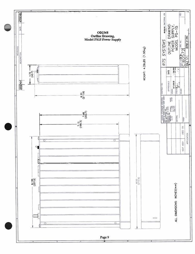
Dimensions
HeightWidth
Depth
The PS 15 is one rack unit high and one-half rack wide. Asingle PS 15 may be rack -mounted singly or two PS 15. s maybe mounted side-by-side.
1.72 inches (44 millimeters)8.186 inches (207.9 millimeters)8.33 inches (211.6 millimeters)
WeightPSl5MCPlMCP2
4.29 pounds (1.95 kilograms)1.0 pounds (0.454 kilograms)1.0 pounds (0.454 kilograms)
FinishThennoplastic front panel. aluminum case. light grayfinish
Page 4

SECTION 2: INSTALLATION at 800 milliamperes when connected in series, but with100 volts at the primaries the output voltage is 26 volts.2.1 MECIIANICAL INSTALLATION
Note: The European version of the Model PSIS isequipped with a special three conductor European powercord / plug set. The plug is the a CEE7n style rated for234 volt /10 to 16 ampere service. The European versionis also equipped with a metric fuse holder and aninternationaJ S by 20 millimeter fu~.
The Model PSl5 can be installed in 3 ways: a single unitmounted in a half rack space using an optional ModclMCP2 Kit for rack mounting a single unit; or two PSl5supplies mounted side by side using the optional MCPlKit for rack mounting two units side by sidc; or frcestanding using the optional MCP8 Kit for adding sidechannels for non-rack mounting portable 1,Ise.
2.4 ELEcrRICAL PERFORMANCE AND LOADING2.2 OUTPUTS
Located on the back panel are the outputs. The PS15 isdesigned to accept A3F 3-pin female connectors.
The first table on the next page shows operating distancesversus model numbers for the PS15 power supply. Thesecond table on the next page shows the maximumnumber of user stations that the PS15 can sustain. Forcombinations of stations, multiply the current values inthe first table times the number of units of that type. Thesum of all the currents should be less than 1 ampere forthe PS15.
2.3 POWER and INPUT POWER SELECTION
2.5 TANDEM OPERATION
Two Model PS 15 power supplies can be used in tandem todouble the number of stations that can be powered. First,the stations are divided between the supplies. Then, astereo patch cord is plugged into the stereo jack on the rearpanel of each supply. The DUAL/NORMAL switch is setto DUAL. This switch corrects the halving of theimpedance of two supplies in parallel by doubling theimpedance of each supply from 200 to 400 ohms. The linesignal levels are maintained because the net impedance isnow 200 ohms.
The power cord is attached to the rear panel. Powerselection is normally done at the factory. If field changeof the input mains voltage is required, disconnect thepower, open the case, and set jumpers as follows (usinglayout diagram on page 10):
For 117 V AC operation, T1 is Signal TransformerLP56-425 or equivalent; install W1, W2, W4, and W6,remove W3 and W5. * (Standard-American ]
For 234 V AC operation, T1 is Signal TransformerLP56-425 or equivalent; install W3, W4, and W6,remove W1, W2, and W5. * [*P Option-European]
For 100 V AC operation, TI is Signal TransformerLP30-800 or equivalent: install Wl, W2, and W5,remove W3, W4, and W6. ** [#D Option-Japanese)
The fuse must aJso be changed to the rating shown on therear panel. 2.6 AUDIO OUTPUT I INPUT
The AUDIO COUPLING CHI-CH2 jack on the rear panelprovides an unbuffered, unbalanced audio output for eachof the two channels. The level ranges from-10 dBu to 0 dBu. An isolation transformer isrecommended to prevent a ground loop between theintercom system common and other grounds.
.Transformer LP56-425 is a dual primary, dual secondarytransformer. The primaries are 115 volts each. The twosecondaries are rated 28 volts at 850 milliamperes whenconnected in parallel. For 115 volt operation, theprimaries are in parallel, and the secondaries are inparallel. For 230 volt operation, the primaries are inseries, and the secondaries are in parallel.
The AUDIO COUPLING jack may also be used to input asignal into the system. Use at least a 2.2 kilohm resistor inseries with the signal source to prevent loading of the RTSSystems intercom line. Use an audio isolation tranformerto prevent ground loops.
..Transformer LP30-800 is a dual primary, dualsecondary transformer. The primaries are normally rated115 volts each, but jn this case will be operated at 100volts each. The secondaries are normally rated at 30 volts
Page 5
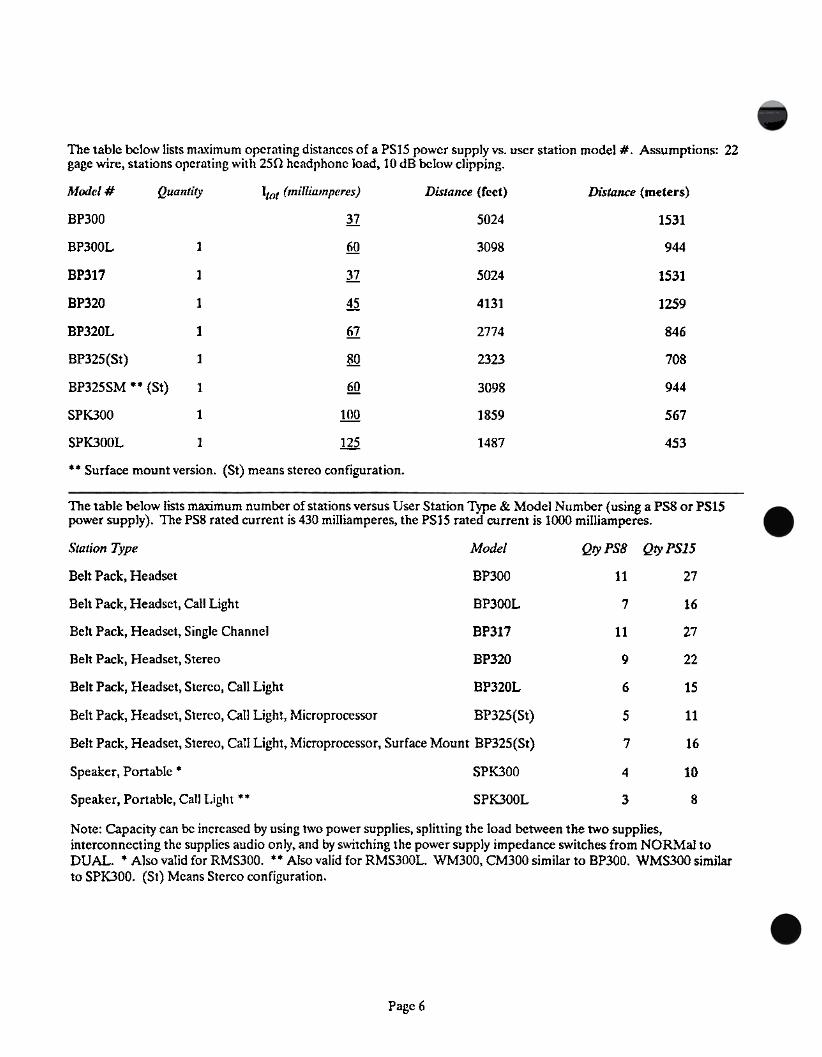
The table bclow lists maximum orcrating distanccs of a PS15 powcr supply vs. user station model # .Assumptions: 22gage wire, stations orcrating with 250 hcadphonc load, 10 dB bclow clipping.
Model # Quantity Itot (milliamperes) Distance (rcct) Distance (meters)
BP300 II
fill
15315024
BP300L 1 3098 944
BP317 1 n
~
5024 1531
BP320 1 4131 1259
BP320L 1 .Q1
~
2774 846
BP325(St)
BP325SM ..(St)
1 2323 708
1 @
1QQ
ill
3098 944
SPK300 1 1859 567
SPK300L 1 1487 453
..Surface mount version. (St) means stereo configuration.
The table below lists maximum number of stations versus User Station Type & Model Number (using a PS8 or PS15power supply). The PS8 rated current is 430 milliamperes, the PS15 rated current js 1000 milliamperes.
Station Type Model Qty PSB Qty PS15
Belt Pack, Headset BP300 II 27
Belt Pack, Headset, CalI Light BP300L 7 16
Belt Pack, Headset, Single Channel BP317 2711
Belt Pack, Headset, Stereo BP320 9 22
Belt Pack, Headset, Stereo, Call Light BP320L 6 15
Belt Pack, Headset, Stereo, Call Light, Microprocessor BP325(St)
Belt Pack, Headset, Stereo, Call Light, Microprocessor, Surface Mount BP325(St)
5 11
7 16
Speaker, Portable . SPK300 4 10
SPK300LSpeaker, Portable, Call Light ** 3 8
Note: Capacity can be increased by using two power supplies, splitting the load between the two supplies,interconnecting the supplies audio only, and by switching the power supply impedance switches from NORMal toDUAL. .Also valid for RMS300. ..Also valid for RMS300L. WM300, CM300 similar to BP300. WMS300 similarto SPK300. (St) Means Stereo configuration.
Page 6

SEcrlON 3: OPERATING INSTRUcrlONS
Figure 3-1
Model PS15 Front Panel
Figure 3.2
Model PSIS Rear Panel
Page 7
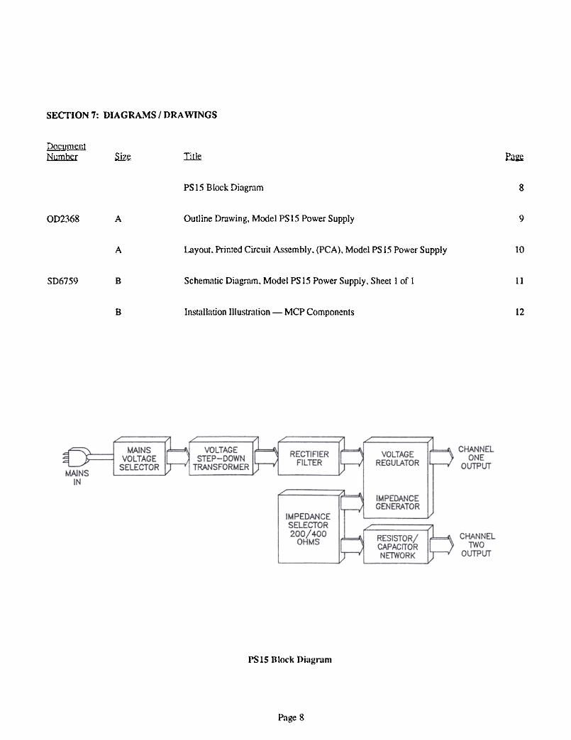
SECTION 7: DIAGRAMS / DRA WINGS
DocumentNumber ~ Ii1le. ~
PSIS Block Diagram 8
9OD2368 A Outline Drawing, Model PS 15 Power Supply
A Layout, Printed Circuit Assembly, (PCA), Model PS 15 Power Supply 10
Schematic Diagram. Model PS 15 Power Supply. Sheet 1 of 1 11SD6759 B
B 12Installation Illustration -MCP Components
PSIS Block Diagram
Page 8
! I ~I~
Ii ~I~"'
~Iffi IOD2368
Outline Drawing,Model PS15 Power Supply
01~1!)~~'--"
U)ID-.J01N
..t
.:.:I<:>W3:
JillNI"...
1~~I~j
.illr
!Nr::-r-. .
.I')
~.!-
1-
I 9 I ';0I w ~I'.I ~ ~I ,
~
tIr
N
51 '
" ,
oi ,,"""
r'1""'i'r'1~
cxiE
U)r::-0. .
.N.t--O
~
0';;;'~O
,..:~~
C::j
l O
w'Q;'00 .~r--
00
OO~ EE
'--'(/)4)Iu~
VizoViz4)~O
-J-J«
~
Page 9
(n"""
!:;5f.:::
~(n
~a:::
(!)z
~0::0
wz::if-:)0
~0-0-:)tn
(I::w3o0-
In
IU)a-
--1LLJoOL

Layout, Printed CircuitAssembly, Model PSIS
Power Supply
Page 10


rMPEDANCE SELECT
(REAR PANEL)
~
0'4'N523'e5.'V
VOLTAGES INDICATED BY TEST POINTS HAVE 2~ TO!..ERANCE.TOP VALUE IS NO LOAD CONDITION. BOTTOM VALUE ISFULL LOAD (1 AMP) CONDITION. VOLTAGES APPLY TO INPUTVOLTAGES SHOWN.
50'5'N523'B5.'V
G FOR 1OOVAC OPERATION:INSTALL W1.W2 AND WS.USE TRANSFORMER (11SVX2.1SVX2.24VA) RTSlf23O1-OO27-OO.
FOR 117VAC OPERATION:INSTALL W1.W2.W4 AND W6.USE TRANSFORMER (11SVX2.28VX2.24VA) RTSII23O1-OO26-OO.
FOR 234VAC OPERATION:INSTALL W3.W4 AND W6.USE TRANSFORMER (11SVX2.28VX2.24VA) RTSlf23O1-OO26-OO.
~ THERMAL BREAKER 95 DEGREES CELS~US OPEN~NG TEMPERATURELOCATED BETWEEN T1 AND T2.
2. CAPACrTANCE VALUES SHOWN: MrCROFARADS/VOLTS.
,. ALL RESrSTORS ARE rN OHMS. ,/4- WATT. CARBON FrLM. +-5~.
NOTES: UNLESS OTHERWISE SPECIFIED Page 11
I CONTRACT No.1
IRTS SYSTEMS Bu'.bank. Callfa'.nla---
iD'.ownI R.NErLsoNc:necked
SCHEMATrC DrAGRAM. TW POWER SUPPLY.MODEL PS15
DWG NOSIZEJ:ssuedNOT USED: 013
LAST USED: 017 .D2O.F"1.J1.P3.R27 .52. T2. TP7 .W7.U1.DS1 -..,-,1
[ I I n II
J PORTABLE D SELF STANDING
WITH MCP8
PS15
I: [ I I n II
1;] SINGLE o RACK MOUNT
o D 0 WITH MCP2
PS15
~ 1 Ii IIU D PS15 I I n II
]) DUAL o RACK MOUNT
D o WITH MCP1
PS15
I fffffi(f). o 011
]] DUAL (f) .O 0 o RACK MOUNT
o WITH MCP 1MRT327 AND MRT327
=
~ III II
U PS15 =
I a!E~.~.0.@II' ~
D DUAL (() .: ..0. @ o RACK MOUNT
o WITH MCP 1MCE325 AND MCE325
[';I 110 II
~ PS15
Installation Illustration'---MCP Components
Page 12