Model predictive control. A review of its applications in ...
13
1 Model Predictive Control: A Review of Its Applications in Power Electronics Sergio Vazquez, Jose I. Leon, Leopoldo G. Franquelo, Jose Rodriguez, Hector A. Young, Abraham Marquez and Pericle Zanchetta Abstract—Model predictive control (MPC) for power convert- ers and drives is a control technique that has gained attention into the research community. The main reason is that although MPC presents high computational burden it can handle multivariable case and system constrains and nonlinearities easily in a very intuitive way. Taking advantage of that, MPC has been success- fully used for different applications such as active front end, power converters connected to RL loads, uninterruptible power supplies and high performance drive for induction machines among others. This paper provides a review of the application of MPC in the power electronics area. I. I NTRODUCTION M ODEL-BASED predictive control (MPC) presents a dramatic advance in the theory of modern automatic control [1]. Originally, MPC was studied and applied in the process industry, where it has been in use for decades [2]. Now, predictive control is being considered in other areas, such as power electronics and drives [3]–[6]. The reason for the growing interest in the use of MPC in this field is the existence of very good mathematical models to predict the behavior of the variables under control in electrical and mechanical systems. In addition, today’s powerful microprocessors can perform the large amount of calculations needed in MPC at high speed and reduced cost. The analysis of the research works published in the pe- riod form 2007 to 2012 in IEEE xplorer r performing a search using the keywords ”predictive” and ”power converters” generate more than 200 papers of MPC applied to PWM power converters published in conferences and journals [7]. The applications covered by these research works can be categorized in four main groups: Grid connected converters, inverters with RL output load, inverters with output LC filters and high performance drives. Fig. 1 shows how these research works are distributed among these four groups. It is also interesting to study how these categories have attracted the attention of the research community along the last years. Fig. 2 and Fig. 3 present information about this issue. Fig. 2 shows that grid connected converters and high performance drives are the application where researchers have paid more attention being a current focus of interest. Fig. 3 addresses that research community attention has not decrease in this period and it is still increasing. It should be noticed the for all categories the cumulative line trends are positives. S. Vazquez, J.I Leon, L.G. Franquelo and A. Marquez are with the Electronic Engineering Department, Universidad de Sevilla (Spain), (e-mail: [email protected]). Grid conected Motor drives Inverter with output LC filter Inverter with RL load Fig. 1. Research works of MPC for PWM power converters published in IEEE conferences and journals from 2007 to 2012: Distribution regarding applications. 0 2 4 6 8 10 12 14 16 18 20 2007 2008 2009 2010 2011 2012 Grid conected Motor drives Inverter with output LC filter Inverter with RL load Fig. 2. Research works of MPC for PWM power converters published in IEEE conferences and journals from 2007 to 2012: Distribution regarding applications and year of publication. 0 10 20 30 40 50 60 70 80 90 2007 2008 2009 2010 2011 2012 Grid conected Motor drives Inverter with output LC filter Inverter with RL load Fig. 3. Research works of MPC for PWM power converters published in IEEE conferences and journals from 2007 to 2012: Cumulative analysis for each application category. This paper presents the use of MPC for the four main cate- gories of applications for PWM power converters that can be found in the literature. This includes a variety of applications like: Grid connected converters; Inverters with RL output load, Inverters with output LC filters and High performance drives. Basic issues of well established MPC algorithms are presented for these applications and new challenges for MPC control for
Transcript of Model predictive control. A review of its applications in ...
1
Model Predictive Control: A Review of ItsApplications in Power Electronics
Sergio Vazquez, Jose I. Leon, Leopoldo G. Franquelo, Jose Rodriguez, Hector A. Young, Abraham Marquez andPericle Zanchetta
Abstract— Model predictive control (MPC) for power convert-ers and drives is a control technique that has gained attention intothe research community. The main reason is that although MPCpresents high computational burden it can handle multivariablecase and system constrains and nonlinearities easily in a veryintuitive way. Taking advantage of that, MPC has been success-fully used for different applications such as active front end,power converters connected to RL loads, uninterruptible powersupplies and high performance drive for induction machinesamong others. This paper provides a review of the applicationof MPC in the power electronics area.
I. INTRODUCTION
MODEL-BASED predictive control (MPC) presents adramatic advance in the theory of modern automatic
control [1]. Originally, MPC was studied and applied in theprocess industry, where it has been in use for decades [2].Now, predictive control is being considered in other areas, suchas power electronics and drives [3]–[6]. The reason for thegrowing interest in the use of MPC in this field is the existenceof very good mathematical models to predict the behaviorof the variables under control in electrical and mechanicalsystems. In addition, today’s powerful microprocessors canperform the large amount of calculations needed in MPC athigh speed and reduced cost.
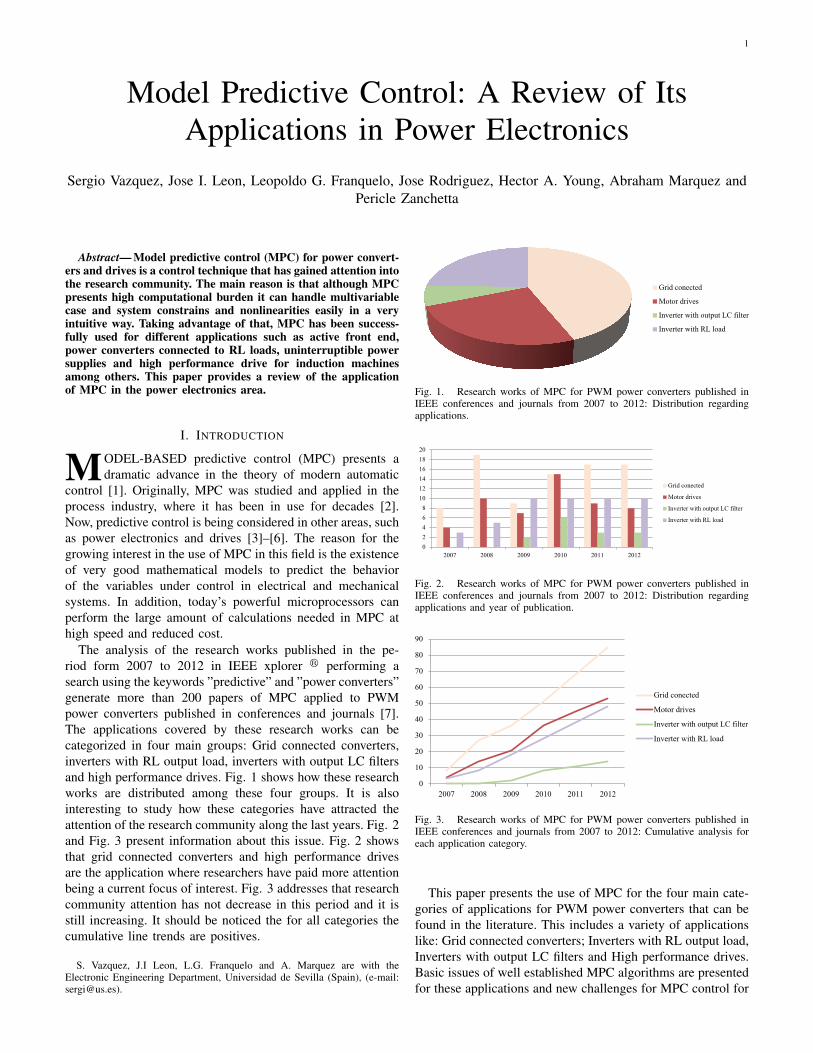
The analysis of the research works published in the pe-riod form 2007 to 2012 in IEEE xplorer r performing asearch using the keywords ”predictive” and ”power converters”generate more than 200 papers of MPC applied to PWMpower converters published in conferences and journals [7].The applications covered by these research works can becategorized in four main groups: Grid connected converters,inverters with RL output load, inverters with output LC filtersand high performance drives. Fig. 1 shows how these researchworks are distributed among these four groups. It is alsointeresting to study how these categories have attracted theattention of the research community along the last years. Fig. 2and Fig. 3 present information about this issue. Fig. 2 showsthat grid connected converters and high performance drivesare the application where researchers have paid more attentionbeing a current focus of interest. Fig. 3 addresses that researchcommunity attention has not decrease in this period and it isstill increasing. It should be noticed the for all categories thecumulative line trends are positives.
S. Vazquez, J.I Leon, L.G. Franquelo and A. Marquez are with theElectronic Engineering Department, Universidad de Sevilla (Spain), (e-mail:[email protected]).
Grid conected
Motor drives
Inverter with output LC filter
Inverter with RL load
Fig. 1. Research works of MPC for PWM power converters published inIEEE conferences and journals from 2007 to 2012: Distribution regardingapplications.
0
2
4
6
8
10
12
14
16
18
20
2007 2008 2009 2010 2011 2012
Grid conected
Motor drives
Inverter with output LC filter
Inverter with RL load
Fig. 2. Research works of MPC for PWM power converters published inIEEE conferences and journals from 2007 to 2012: Distribution regardingapplications and year of publication.
0
10
20
30
40
50
60
70
80
90
2007 2008 2009 2010 2011 2012
Grid conected
Motor drives
Inverter with output LC filter
Inverter with RL load
Fig. 3. Research works of MPC for PWM power converters published inIEEE conferences and journals from 2007 to 2012: Cumulative analysis foreach application category.
This paper presents the use of MPC for the four main cate-gories of applications for PWM power converters that can befound in the literature. This includes a variety of applicationslike: Grid connected converters; Inverters with RL output load,Inverters with output LC filters and High performance drives.Basic issues of well established MPC algorithms are presentedfor these applications and new challenges for MPC control for
2
power converters and drives are also addressed.
II. THE MPC CONTROL STRATEGY
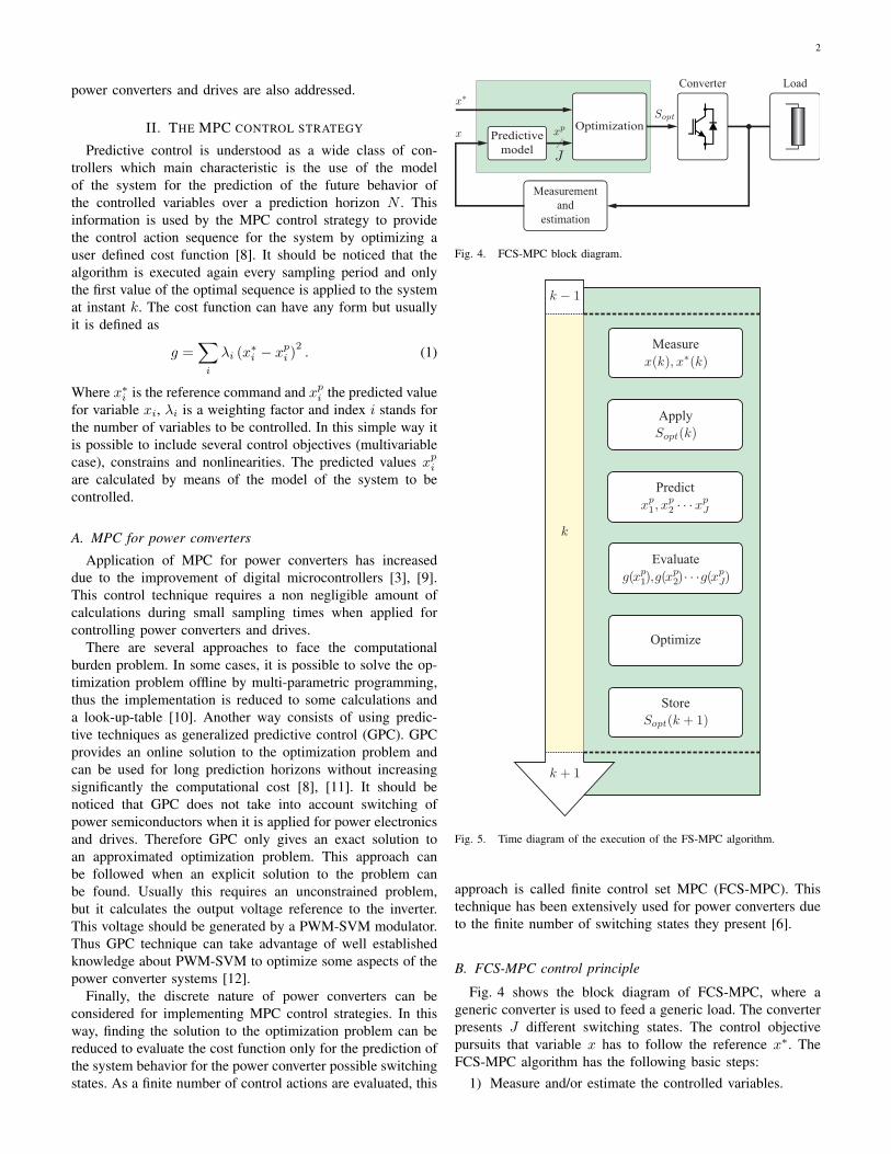
Predictive control is understood as a wide class of con-trollers which main characteristic is the use of the modelof the system for the prediction of the future behavior ofthe controlled variables over a prediction horizon N . Thisinformation is used by the MPC control strategy to providethe control action sequence for the system by optimizing auser defined cost function [8]. It should be noticed that thealgorithm is executed again every sampling period and onlythe first value of the optimal sequence is applied to the systemat instant k. The cost function can have any form but usuallyit is defined as
g =∑i
λi (x∗i − xpi )
2. (1)
Where x∗i is the reference command and xpi the predicted valuefor variable xi, λi is a weighting factor and index i stands forthe number of variables to be controlled. In this simple way itis possible to include several control objectives (multivariablecase), constrains and nonlinearities. The predicted values xpiare calculated by means of the model of the system to becontrolled.
A. MPC for power converters
Application of MPC for power converters has increaseddue to the improvement of digital microcontrollers [3], [9].This control technique requires a non negligible amount ofcalculations during small sampling times when applied forcontrolling power converters and drives.
There are several approaches to face the computationalburden problem. In some cases, it is possible to solve the op-timization problem offline by multi-parametric programming,thus the implementation is reduced to some calculations anda look-up-table [10]. Another way consists of using predic-tive techniques as generalized predictive control (GPC). GPCprovides an online solution to the optimization problem andcan be used for long prediction horizons without increasingsignificantly the computational cost [8], [11]. It should benoticed that GPC does not take into account switching ofpower semiconductors when it is applied for power electronicsand drives. Therefore GPC only gives an exact solution toan approximated optimization problem. This approach canbe followed when an explicit solution to the problem canbe found. Usually this requires an unconstrained problem,but it calculates the output voltage reference to the inverter.This voltage should be generated by a PWM-SVM modulator.Thus GPC technique can take advantage of well establishedknowledge about PWM-SVM to optimize some aspects of thepower converter systems [12].
Finally, the discrete nature of power converters can beconsidered for implementing MPC control strategies. In thisway, finding the solution to the optimization problem can bereduced to evaluate the cost function only for the prediction ofthe system behavior for the power converter possible switchingstates. As a finite number of control actions are evaluated, this
Converter Load
Predictive
model
Optimization
Measurement
and
estimation
J
Fig. 4. FCS-MPC block diagram.
Optimize
Measure
Apply
Store
Evaluate
Predict
Fig. 5. Time diagram of the execution of the FS-MPC algorithm.
approach is called finite control set MPC (FCS-MPC). Thistechnique has been extensively used for power converters dueto the finite number of switching states they present [6].
B. FCS-MPC control principle
Fig. 4 shows the block diagram of FCS-MPC, where ageneric converter is used to feed a generic load. The converterpresents J different switching states. The control objectivepursuits that variable x has to follow the reference x∗. TheFCS-MPC algorithm has the following basic steps:
1) Measure and/or estimate the controlled variables.
3
n
Load
Fig. 6. Power circuit of the AFE.
2) Apply the optimal switching state (computed in theprevious sampling period).
3) For every switching state of the converter, predict (usingthe mathematical model) the behavior of variable x inthe next sampling interval xp.
4) Evaluate the cost function, or error, for each predictionas, for instance: g = |x∗ − xp|
5) Select the switching state that minimizes the cost func-tion, Sopt and store it for being applied to the converterat the next sampling period.
As discussed in [13] it is convenient to perform theprediction two time steps ahead, in order to reduce the effectsof the delay introduced by the implementation of FCS-MPC ina digital platform. Another possibility to avoid the effect of thecomputation delay is to use a control strategy that only requiresa small computation time. In this way, the optimal switchingstate is applied to the converter with this small delay, andbefore the following sampling instant [14]. A time diagramof the execution of the FCS-MPC algorithm is presented inFig.5.
III. MPC FOR GRID CONNECTED CONVERTERS
Several applications use grid connected converters as oneof their main components. This application includes activefront end (AFE) for high performance drives, rectifiers, gridintegration of renewable energies like wind or PV, energystorage systems, and are also used in FACTS devices asSTATCOM, active power filter, or as a part of an UPFC orUPQC [15]–[17].
A. Control of an Active Front End
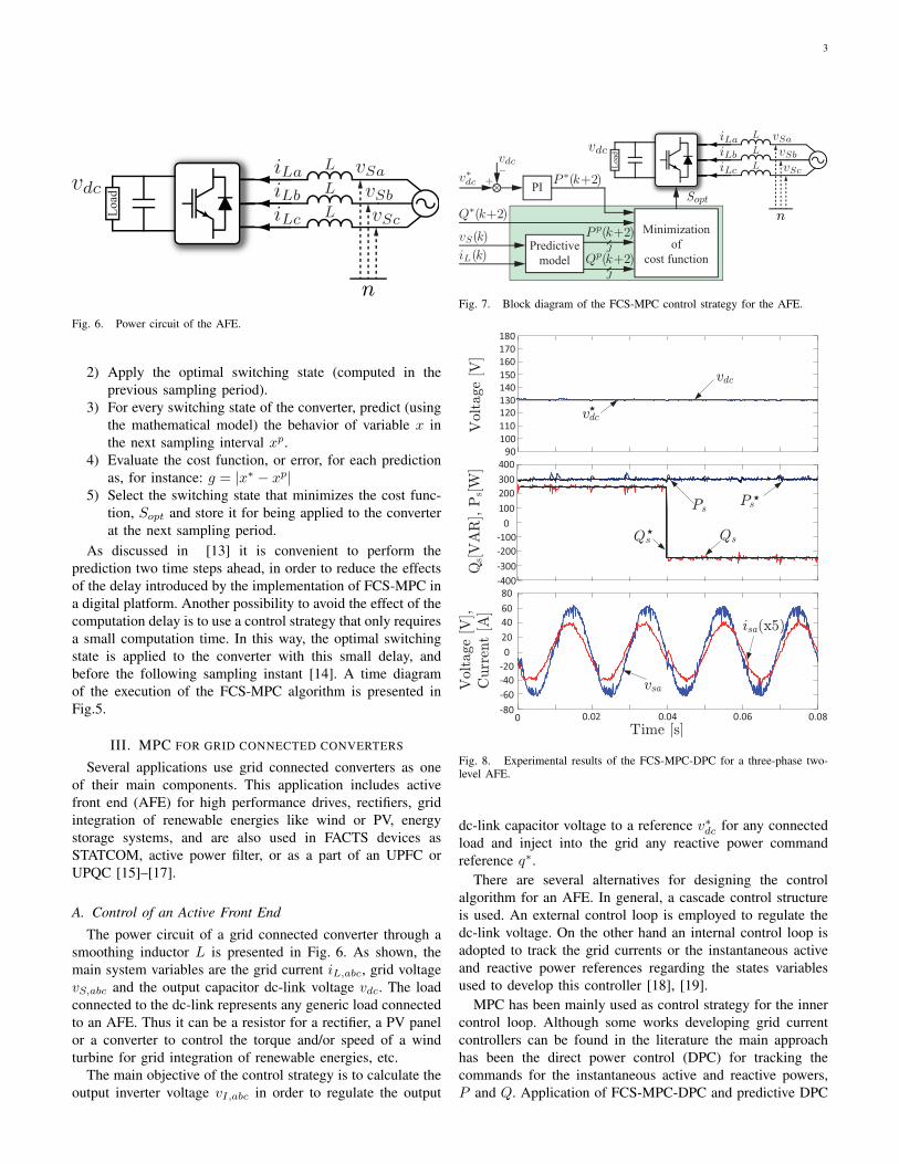
The power circuit of a grid connected converter through asmoothing inductor L is presented in Fig. 6. As shown, themain system variables are the grid current iL,abc, grid voltagevS,abc and the output capacitor dc-link voltage vdc. The loadconnected to the dc-link represents any generic load connectedto an AFE. Thus it can be a resistor for a rectifier, a PV panelor a converter to control the torque and/or speed of a windturbine for grid integration of renewable energies, etc.
The main objective of the control strategy is to calculate theoutput inverter voltage vI,abc in order to regulate the output
J
Predictive
model
Minimization
of
cost function
Sopt
n
Lo
ad
J
PI
Fig. 7. Block diagram of the FCS-MPC control strategy for the AFE.
Fig. 8. Experimental results of the FCS-MPC-DPC for a three-phase two-level AFE.
dc-link capacitor voltage to a reference v∗dc for any connectedload and inject into the grid any reactive power commandreference q∗.
There are several alternatives for designing the controlalgorithm for an AFE. In general, a cascade control structureis used. An external control loop is employed to regulate thedc-link voltage. On the other hand an internal control loop isadopted to track the grid currents or the instantaneous activeand reactive power references regarding the states variablesused to develop this controller [18], [19].
MPC has been mainly used as control strategy for the innercontrol loop. Although some works developing grid currentcontrollers can be found in the literature the main approachhas been the direct power control (DPC) for tracking thecommands for the instantaneous active and reactive powers,P and Q. Application of FCS-MPC-DPC and predictive DPC
4
n
Load
J
Predictive
model
P-DPCJ
PI
PWM-SVM
Sabc
vI;abc
Fig. 9. Block diagram of the P-DPC control strategy for the AFE.
with SVM modulation strategy (P-DPC) can be considered aswell established [14], [20]–[22].
The block diagram of the FCS-MPC-DPC strategy is pre-sented in Fig. 7. In this case, the model of the system is used topredict values of the instantaneous active and reactive powerover a prediction horizon N = 1, P p(k + 2), Qp(k + 2).In [14], [20] a three-phase two-level AFE was controlledadopting this strategy. The algorithm was developed in theαβ frame. Therefore, only the seven possible output vectorswere considered to perform the prediction, thus the numberof switching states is J = 7. Once the seven output voltagepredictions are calculated the cost function
g = (P ∗(k+2)− P p(k+2))2
+ (Q∗(k+2)−Qp(k+2))2 (2)
is minimized in order to find the inverter output vector thatshould be applied in the next sampling period.
Fig. 8 presents experimental results obtained using thisstrategy [14]. It should be noticed that predictions in instants(k+ 2) are used in order to compensate for the control actiondelay of the digital implementation of the control strategy.
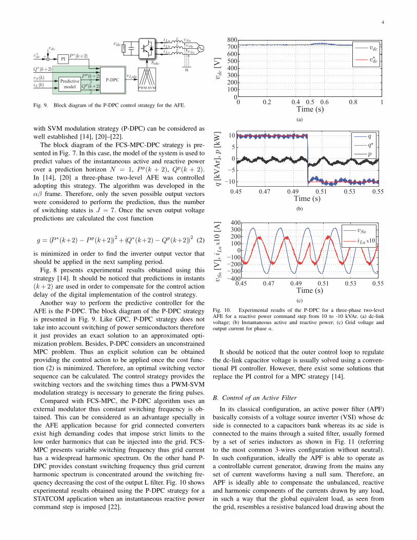
Another way to perform the predictive controller for theAFE is the P-DPC. The block diagram of the P-DPC strategyis presented in Fig. 9. Like GPC, P-DPC strategy does nottake into account switching of power semiconductors thereforeit just provides an exact solution to an approximated opti-mization problem. Besides, P-DPC considers an unconstrainedMPC problem. Thus an explicit solution can be obtainedproviding the control action to be applied once the cost func-tion (2) is minimized. Therefore, an optimal switching vectorsequence can be calculated. The control strategy provides theswitching vectors and the switching times thus a PWM-SVMmodulation strategy is necessary to generate the firing pulses.
Compared with FCS-MPC, the P-DPC algorithm uses anexternal modulator thus constant switching frequency is ob-tained. This can be considered as an advantage specially inthe AFE application because for grid connected convertersexist high demanding codes that impose strict limits to thelow order harmonics that can be injected into the grid. FCS-MPC presents variable switching frequency thus grid currenthas a widespread harmonic spectrum. On the other hand P-DPC provides constant switching frequency thus grid currentharmonic spectrum is concentrated around the switching fre-quency decreasing the cost of the output L filter. Fig. 10 showsexperimental results obtained using the P-DPC strategy for aSTATCOM application when an instantaneous reactive powercommand step is imposed [22].
10 0.2 0.4 0.5 0.6 0.80
100200300400500600700800
Time (s)
vdc [
V]
vdc
v?dc
(a)
0.45 0.47 0.49 0.51 0.53 0.55
−10
−5
0
5
10
Time (s)
q [
kV
Ar]
, p
[k
W]
q
q?
p
(b)
0.45 0.47 0.49 0.51 0.53 0.55−400
−300−200−100
0100200300400
Time (s)
vSa [
V],
iLa x
10
[A
]
vSa
iLa x10
(c)
Fig. 10. Experimental results of the P-DPC for a three-phase two-levelAFE for a reactive power command step from 10 to -10 kVAr. (a) dc-linkvoltage; (b) Instantaneous active and reactive power; (c) Grid voltage andoutput current for phase a.
It should be noticed that the outer control loop to regulatethe dc-link capacitor voltage is usually solved using a conven-tional PI controller. However, there exist some solutions thatreplace the PI control for a MPC strategy [14].
B. Control of an Active Filter
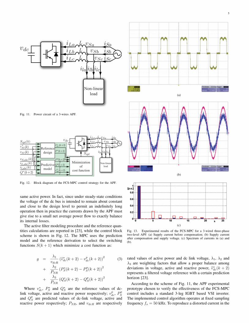
In its classical configuration, an active power filter (APF)basically consists of a voltage source inverter (VSI) whose dcside is connected to a capacitors bank whereas its ac side isconnected to the mains through a suited filter, usually formedby a set of series inductors as shown in Fig. 11 (referringto the most common 3-wires configuration without neutral).In such configuration, ideally the APF is able to operate asa controllable current generator, drawing from the mains anyset of current waveforms having a null sum. Therefore, anAPF is ideally able to compensate the unbalanced, reactiveand harmonic components of the currents drawn by any load,in such a way that the global equivalent load, as seen fromthe grid, resembles a resistive balanced load drawing about the
5
Non-linear
load
ilbila ilc
iSa
iSb
iSc
Fig. 11. Power circuit of a 3-wires APF.
J
Predictive
model
Minimization
of
cost function
Sopt
J Non-linear
load
ilbila ilc
iSaiSbiSc
Reference
design
Sopt(k)
vS,abc(k)
iL,abc(k)
il,abc(k)
J
Fig. 12. Block diagram of the FCS-MPC control strategy for the APF.
same active power. In fact, since under steady-state conditionsthe voltage of the dc bus is intended to remain about constantand close to the design level to permit an indefinitely longoperation then in practice the currents drawn by the APF mustgive rise to a small net average power flow to exactly balanceits internal losses.
The active filter modeling procedure and the reference quan-tities calculations are reported in [23], while the control blockscheme is shown in Fig. 12. The MPC uses the predictionmodel and the reference derivation to select the switchingfunctions S(k + 1) which minimize a cost function as:
g =λ1vdcR
(v∗dc(k + 2)− vpdc(k + 2))2 (3)
+λ2PSR
(P ∗S(k + 2)− P pS(k + 2))
2
+λ3PSR
(Q∗S(k + 2)−QpS(k + 2))
2
Where v∗dc, P∗S and Q∗
S are the reference values of dc-link voltage, active and reactive power respectively; vpdc, P
pS
and QpS are predicted values of dc-link voltage, active andreactive power respectively; PSR, and vdcR are respectively
(a)
(b)
(c)
Fig. 13. Experimental results of the FCS-MPC for a 3-wired three-phasetwo-level APF. (a) Supply current before compensation; (b) Supply currentafter compensation and supply voltage. (c) Spectrum of currents in (a) and(b).
rated values of active power and dc link voltage, λ1, λ2 andλ3 are weighting factors that allow a proper balance amongdeviations in voltage, active and reactive power, v∗dc(k + 2)represents a filtered voltage reference with a certain predictionhorizon [23].
According to the scheme of Fig. 11, the APF experimentalprototype chosen to verify the effectiveness of the FCS-MPCcontrol includes a standard 3-leg IGBT based VSI inverter.The implemented control algorithm operates at fixed samplingfrequency fs = 50 kHz. To reproduce a distorted current in the
6
grid, a non-linear load constituted by a 3-phase diode bridgerectifier supplying a resistor having a rated power PSR = 5kW was considered [23].
At full power the load draws the distorted current in Fig. 13awhere the vertical axis measures 5A/div while the horizontalone 10ms/div; after APF compensation the mains currentswaveform is shown in Fig. 13b (5A/div) together with thesupply voltage (100V/div). The compensation action resultsin a unity power factor operation and quasi sinusoidal currentwith a superimposed high-frequency ripple due to invertercommutation and the nature of the FCS-MPC control actionitself. The achieved benefits and therefore the effectiveness ofthe control action were also confirmed in spectral terms bycomparing the mains current spectrum and the load currentspectrum in Fig. 13c, resulting in a reduction of major low-order harmonics, which permits to achieve a THD< 5%starting from a THD> 29%, where the THD is calculatedincluding up to the 50th harmonic.
IV. MPC FOR INVERTERS WITH RL-LOAD
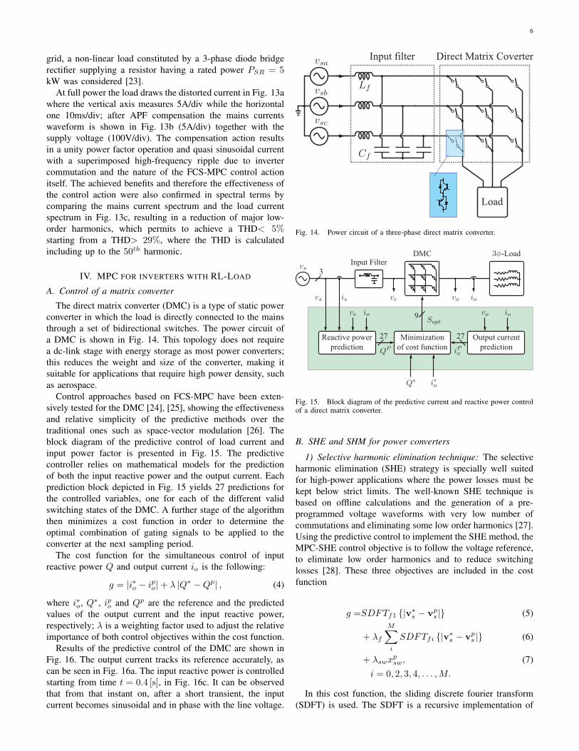
A. Control of a matrix converter
The direct matrix converter (DMC) is a type of static powerconverter in which the load is directly connected to the mainsthrough a set of bidirectional switches. The power circuit ofa DMC is shown in Fig. 14. This topology does not requirea dc-link stage with energy storage as most power converters;this reduces the weight and size of the converter, making itsuitable for applications that require high power density, suchas aerospace.
Control approaches based on FCS-MPC have been exten-sively tested for the DMC [24], [25], showing the effectivenessand relative simplicity of the predictive methods over thetraditional ones such as space-vector modulation [26]. Theblock diagram of the predictive control of load current andinput power factor is presented in Fig. 15. The predictivecontroller relies on mathematical models for the predictionof both the input reactive power and the output current. Eachprediction block depicted in Fig. 15 yields 27 predictions forthe controlled variables, one for each of the different validswitching states of the DMC. A further stage of the algorithmthen minimizes a cost function in order to determine theoptimal combination of gating signals to be applied to theconverter at the next sampling period.
The cost function for the simultaneous control of inputreactive power Q and output current io is the following:
g = |i∗o − ipo|+ λ |Q∗ −Qp| , (4)
where i∗o, Q∗, ipo and Qp are the reference and the predictedvalues of the output current and the input reactive power,respectively; λ is a weighting factor used to adjust the relativeimportance of both control objectives within the cost function.
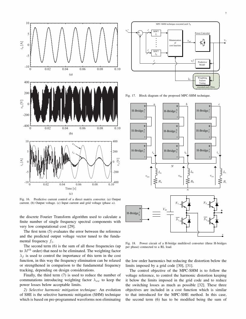
Results of the predictive control of the DMC are shown inFig. 16. The output current tracks its reference accurately, ascan be seen in Fig. 16a. The input reactive power is controlledstarting from time t = 0.4 [s], in Fig. 16c. It can be observedthat from that instant on, after a short transient, the inputcurrent becomes sinusoidal and in phase with the line voltage.
Load
Direct Matrix CoverterInput filter
Fig. 14. Power circuit of a three-phase direct matrix converter.
Input FilterDMC
Minimization
of cost function
9
3
Reactive power
prediction
27 27 Output current
prediction
-Load
Fig. 15. Block diagram of the predictive current and reactive power controlof a direct matrix converter.
B. SHE and SHM for power converters
1) Selective harmonic elimination technique: The selectiveharmonic elimination (SHE) strategy is specially well suitedfor high-power applications where the power losses must bekept below strict limits. The well-known SHE technique isbased on offline calculations and the generation of a pre-programmed voltage waveforms with very low number ofcommutations and eliminating some low order harmonics [27].Using the predictive control to implement the SHE method, theMPC-SHE control objective is to follow the voltage reference,to eliminate low order harmonics and to reduce switchinglosses [28]. These three objectives are included in the costfunction
g =SDFTf1 {|v∗s − vps |} (5)
+ λf
M∑i
SDFTfi {|v∗s − vps |} (6)
+ λswxpsw, (7)
i = 0, 2, 3, 4, . . . ,M.
In this cost function, the sliding discrete fourier transform(SDFT) is used. The SDFT is a recursive implementation of
7
0 0.02 0.04 0.06 0.08 0.10
0
10
5
-10
-5
ia [
A]
(a)
0 0.02 0.04 0.06 0.08 0.10
0
400
200
-400
-200
va [
V]
(b)
Time [s]
is
vs
0 0.02 0.04 0.06 0.08 0.10
0
10
5
-10
-5
is [
A]
0
400
200
-400
-200
vs [
V]
(c)
Fig. 16. Predictive current control of a direct matrix converter. (a) Outputcurrent. (b) Output voltage. (c) Input current and grid voltage (phase a).
the discrete Fourier Transform algorithm used to calculate afinite number of single frequency spectral components withvery low computational cost [29].
The first term (5) evaluates the error between the referenceand the predicted output voltage vector tuned to the funda-mental frequency f1.
The second term (6) is the sum of all those frequencies (upto M th order) that need to be eliminated. The weighting factorλf is used to control the importance of this term in the costfunction, in this way the frequency elimination can be relaxedor strengthened in comparison to the fundamental frequencytracking, depending on design considerations.
Finally, the third term (7) is used to reduce the number ofcommutations introducing weighting factor λsw to keep thepower losses below acceptable limits.
2) Selective harmonic mitigation technique: An evolutionof SHE is the selective harmonic mitigation (SHM) techniquewhich is based on pre-programmed waveforms non eliminating
Predictive
Model
Minimization
of
cost function
SDFT
f0
SDFT
fK
.
J
Weighting
Factors
Tuning
executed each 20ms
MPC-SHM technique executed each Ts
Power Converter
Sopt
λi
J
J
+ -
.
.
.
.
v s *
v s
v s p
Fig. 17. Block diagram of the proposed MPC-SHM technique.
Vdc
-
+
H-Bridge2
a
H-Bridge3
a
H-Bridge2
b
H-Bridge3
b H-Bridge3
c
H-Bridge2
c
H-Bridgek
j
-
+
-
+
-
+
-
+
-
+
-
+
-
+
H-Bridge1
aH-Bridge
1
b H-Bridge1
c
-
+
-
+
-
+
S 1 S 2
S 1 S 2
N
La
Ra
van
Lb
Rb
vbn
Lc
Rc
vcn
n
a b c
ia ib ic
Fig. 18. Power circuit of a H-bridge multilevel converter (three H-bridgesper phase) connected to a RL load.
the low order harmonics but reducing the distortion below thelimits imposed by a grid code [30], [31].
The control objective of the MPC-SHM is to follow thevoltage reference, to control the harmonic distortion keepingit below the limits imposed in the grid code and to reducethe switching losses as much as possible [32]. These threeobjectives are included in a cost function which is similarto that introduced for the MPC-SHE method. In this case,the second term (6) has to be modified being the sum of
8
1.79 1.795 1.8 1.805 1.81 1.815 1.82 1.825 1.83 1.835 1.84
200
300
400
Phas
e V
olt
age v aN
[V]
1.79 1.795 1.8 1.805 1.81 1.815 1.82 1.825 1.83 1.835 1.84
−400
−200
0
200
400
1.79 1.795 1.8 1.805 1.81 1.815 1.82 1.825 1.83 1.835 1.84−300
−200
−100
0
100
200
300
1.79 1.795 1.8 1.805 1.81 1.815 1.82 1.825 1.83 1.835 1.84−15
−10
−5
0
5
10
15
0 500 1000
0
0.2
0.4
0.6
0.8
1
0 500 1000
0
0.2
0.4
0.6
0.8
1
0 500 1000
0
0.2
0.4
0.6
0.8
1
0 500 1000
0
0.2
0.4
0.6
0.8
1
Lin
e V
olt
age v ab
[V]
Load
Volt
age v an[V]
Phas
e C
urr
ents
iabc [
A]
Time [s] Frequncy [Hz]
0
100
Fig. 19. Predictive harmonic mitigation phase output voltage vaN , linevoltage vab, load voltage van and load currents ia,ib,ic for a 7-level CHB.
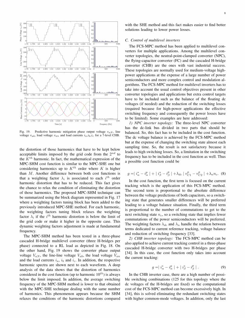
the distortion of those harmonics that have to be kept belowacceptable limits imposed by the grid code from the 2nd tothe Kth harmonic. In fact, the mathematical expression of theMPC-SHM cost function is similar to the MPC-SHE one butconsidering harmonics up to Kth order where K is higherthan M . Another difference between both cost functions isthat a weighting factor λi is associated to each ith orderharmonic distortion that has to be reduced. This fact givesthe chance to relax the condition of eliminating the distortionof those harmonics. The proposed MPC-SHM technique canbe summarized using the block diagram represented in Fig. 17where a weighting factors tuning block has been added to thepreviously introduced MPC-SHE method. For each harmonic,the weighting factors tuning block relaxes the weightingfactor λi if the ith harmonic distortion is below the limit ofthe grid code or make it higher in the opposite case. Thisdynamic weighting factors adjustment is made at fundamentalfrequency.
The MPC-SHM method has been tested in a three-phasecascaded H-bridge multilevel converter (three H-bridges perphase) connected to a RL load as depicted in Fig. 18. Onthe other hand, Fig. 19 shows the converter phase outputvoltage VaN , the line-line voltage Vab, the load voltage Vanand the load currents ia, ib and ic. In addition, the respectiveharmonic spectra are shown next to each waveform. A deepanalysis of the data shows that the distortion of harmonicsconsidered in the cost function (up to harmonic 10th) is alwaysbelow the limit imposed. In addition, the average switchingfrequency of the MPC-SHM method is lower to that obtainedwith the MPC-SHE technique dealing with the same numberof harmonics. This phenomenon appears because the SHMrelaxes the conditions of the harmonic distortions compared
with the SHE method and this fact makes easier to find bettersolutions leading to lower power losses.
C. Control of multilevel inverters
The FCS-MPC method has been applied to multilevel con-verters for multiple applications. Among the multilevel con-verter topologies, the neutral-point-clamped converter (NPC),the flying-capacitor converter (FC) and the cascaded H-bridgeconverter (CHB) are the ones with vast industrial success.These topologies are normally used for medium-voltage high-power applications at the expense of a large number of powersemiconductors and more complex control and modulation al-gorithms. The FCS-MPC method for multilevel inverters has totake into account the usual control objectives present in otherconverter topologies and applications but extra control targetshave to be included such as the balance of the floating dcvoltages (if needed) and the reduction of the switching losses(required because for high-power applications the effectiveswitching frequency and consequently the power losses haveto be limited). Some examples are here addressed:
1) NPC inverter topology: The three-level NPC converterhas the dc-link bus divided in two parts that should bebalanced. So, this fact has to be included in the cost function.The dc voltage balance is achieved by the FCS-MPC methodbut at the expense of changing the switching state almost eachsampling time. So, the result is not satisfactory because itleads to high switching losses. So, a limitation in the switchingfrequency has to be included in the cost function as well. Thusa possible cost function could be
g =| i∗α − ipα | + | i∗β − ipβ | +λdc | v
pC1 − v
pC2 | +λnnc. (8)
In the cost function, the first term is focused on the currenttracking which is the application of this FCS-MPC method.The second term is proportional to the absolute differencebetween the voltage predictions of both capacitors, so a switch-ing state that generates smaller differences will be preferredleading to a voltage balance situation. Finally, the third termis proportional to the number of commutations to get to thenext switching state nc, so a switching state that implies fewercommutations of the power semiconductors will be preferred.The weighting factors λdc and λn handle the relation betweenterms dedicated to current reference tracking, voltage balanceand reduction of switching frequency [33].
2) CHB inverter topology: The FCS-MPC method can bealso applied to achieve current tracking control in a three-phasecascaded H-bridge converter with two H-bridges per phase[34]. In this case, the cost function only takes into accountthe current tracking:
g =| i∗α − ipα | + | i∗β − ipβ | . (9)
In the CHB inverter case, there are a high number of possi-ble switching combinations (125 for this topology where thedc voltages of the H-bridges are fixed) so the computationalcost of the FCS-MPC method can become excessively high. In[34], this is solved eliminating the redundant switching stateswith higher common-mode voltages. In addition, only the last
9
vdc
CapacitorVoltages[V]
100
200
300
400
InverterOutputVoltage[V]
OutputCurrents[A]
100
200
300
400
01
2
34
5
-1
-2-3
-4-5
THD =1.5%c
(a)
vc a1
vc a2
10 20 05 1 5
Time [ms](c)
(b)
ratio 3:2:1
van
ia
ic
ib
0
0
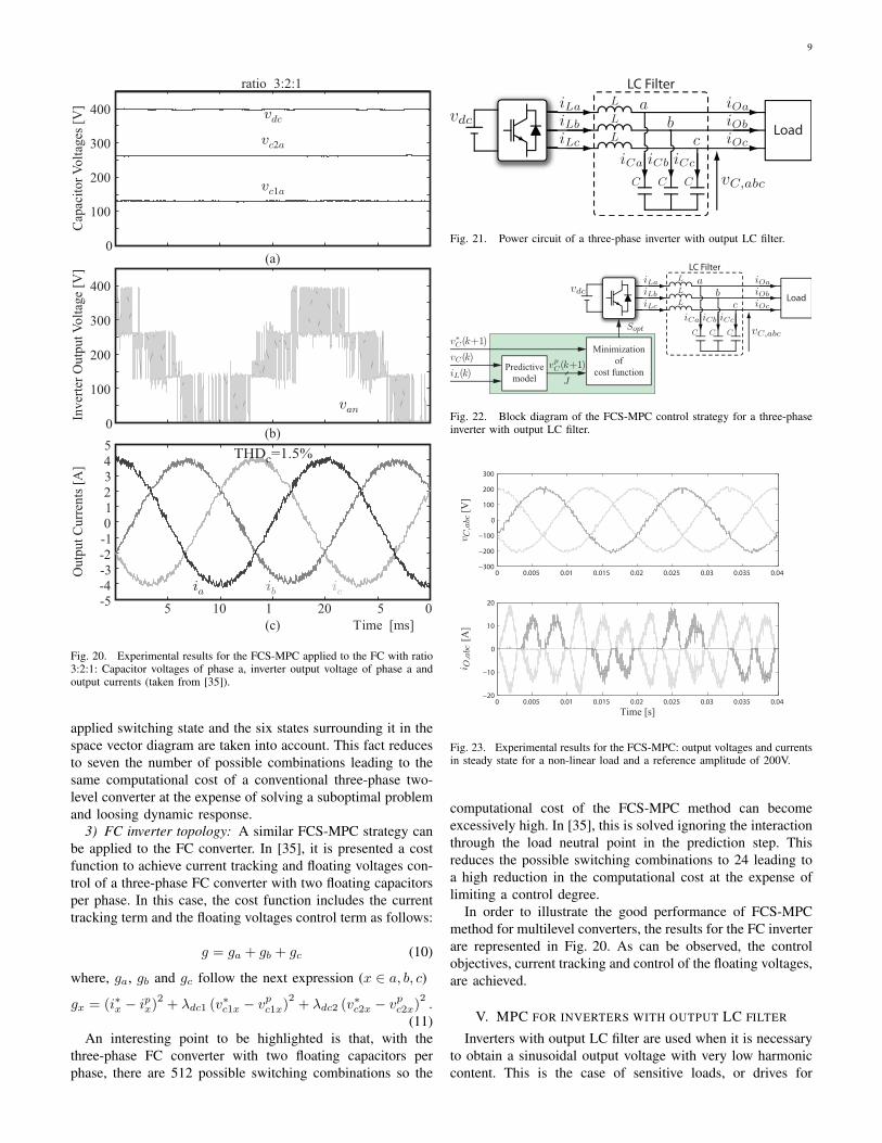
Fig. 20. Experimental results for the FCS-MPC applied to the FC with ratio3:2:1: Capacitor voltages of phase a, inverter output voltage of phase a andoutput currents (taken from [35]).
applied switching state and the six states surrounding it in thespace vector diagram are taken into account. This fact reducesto seven the number of possible combinations leading to thesame computational cost of a conventional three-phase two-level converter at the expense of solving a suboptimal problemand loosing dynamic response.
3) FC inverter topology: A similar FCS-MPC strategy canbe applied to the FC converter. In [35], it is presented a costfunction to achieve current tracking and floating voltages con-trol of a three-phase FC converter with two floating capacitorsper phase. In this case, the cost function includes the currenttracking term and the floating voltages control term as follows:
g = ga + gb + gc (10)
where, ga, gb and gc follow the next expression (x ∈ a, b, c)
gx = (i∗x − ipx)2
+ λdc1 (v∗c1x − vpc1x)
2+ λdc2 (v∗c2x − v
pc2x)
2.
(11)An interesting point to be highlighted is that, with the
three-phase FC converter with two floating capacitors perphase, there are 512 possible switching combinations so the
Load
LC Filter
Fig. 21. Power circuit of a three-phase inverter with output LC filter.
Load
LC Filter
Predictive
model
Minimization
of
cost function
Sopt
J
Fig. 22. Block diagram of the FCS-MPC control strategy for a three-phaseinverter with output LC filter.
0 0.005 0.01 0.015 0.02 0.025 0.03 0.035 0.04−300
−200
−100
0
100
200
300
vC;abc
[V
]
0 0.005 0.01 0.015 0.02 0.025 0.03 0.035 0.04−20
−10
0
10
20
Time [s]
i O;abc
[A
]
Fig. 23. Experimental results for the FCS-MPC: output voltages and currentsin steady state for a non-linear load and a reference amplitude of 200V.
computational cost of the FCS-MPC method can becomeexcessively high. In [35], this is solved ignoring the interactionthrough the load neutral point in the prediction step. Thisreduces the possible switching combinations to 24 leading toa high reduction in the computational cost at the expense oflimiting a control degree.
In order to illustrate the good performance of FCS-MPCmethod for multilevel converters, the results for the FC inverterare represented in Fig. 20. As can be observed, the controlobjectives, current tracking and control of the floating voltages,are achieved.
V. MPC FOR INVERTERS WITH OUTPUT LC FILTER
Inverters with output LC filter are used when it is necessaryto obtain a sinusoidal output voltage with very low harmoniccontent. This is the case of sensitive loads, or drives for

10
PWM-SVM
Load
LC Filter
Predictive
model
GPC
Sabc
vI;abc
Fig. 24. Block diagram of the GPC control strategy for a three-phase inverterwith output LC filter.
machines in order to reduce the input voltage harmonics andincrease its lifespan or avoid problems caused by high valuesof dv/dt. These inverters are also employed when a voltagesource is needed like in FACTS devices as SSSC, DVR oras a part of an UPFC or UPQC. However, its most importantapplication is as the main converter of uninterruptible powersupply systems (UPS).
The power circuit of an inverter with output LC filterconnected to a generic load is shown in Fig. 21. As shown, themain system variables are the output inductor current iL,abc,output capacitor voltage vC,abc, output capacitor current iC,abcand output load current iO,abc. The main objective of thecontrol strategy is to calculate the output inverter voltage vI,abcin order to track an output capacitor voltage reference v∗C,abcfor any connected load.
There are several alternatives for designing the controlalgorithm for an inverter with output LC filter [36]. MPCis a very interesting option for this application, because highperformance of the overall system can be achieved with a verysimple algorithm. Application of FCS-MPC and GPC for anUPS system can also be found in the literature [12], [37].
The block diagram of the FCS-MPC strategy is presentedin Fig. 22. In this case, the model of the system is used topredict the output capacitor voltage over a prediction horizonN = 1, vpC(k + 1). In [37] this strategy was adopted and thecontroller was developed for a three-phase two-level inverterin the αβ frame. Therefore, only the seven possible outputvectors were considered to perform the prediction, thus thenumber of switching states is J = 7. Once the seven outputvoltage predictions are calculated the cost function
g =(v∗C,α − v
pC,α
)2+(v∗C,β − v
pC,β
)2(12)
is minimized in order to find the inverter output vector thatshould be applied in the next sampling period.
Fig. 23 shows experimental results obtained using thisstrategy when a non linear load is connected to the inverter[37]. It should be noticed that iO,abc has been considered asa perturbation. In this way, iO,abc was not measured but aobserver was used to enhance the performance of the system.
Prediction horizons N higher than 1 can provide in somecases better performance than using N = 1. This issue hasbeen investigated for a UPS system using the FCS-MPCstrategy [38]. The main problem is that computation burdenincreases exponentially with N . Therefore it is difficult thepractical implementation of this approach.
Another way to increase the prediction horizon N is to use
0
Time [ms]
vCa
[V
]
vCa
vCa*
vCa - vCa*
200
−200
−150
−100
−50
50
100
150
0 10 20 30 40
(a)
VaO
VaO
*
VaO
*−V
aO
Time [ms]
vCa
[V
]
vCa
vCa*
vCa - vCa*
−200
−150
−100
−50
0
50
100
150
200
0 10 20 30 40
(b)
Fig. 25. System performance for the GPC strategy for different values ofN and λ: (a) Phase a voltage and its reference for N = 5 and λ = 0.0. (b)Phase a voltage and its reference for N = 6 and λ = 1.05.
is
ia
ib
+Induction Machine
-
PI
Predictive
modelEstimate
Minimization
of
cost function
Sopt
J J
Inverter
Fig. 26. Block diagram of the predictive torque control of an inductionmachine.
a GPC strategy to calculate the control action. The GPC usesa CARIMA model to predict the system variables with longprediction horizon values [11]. The block diagram of the GPCstrategy is presented in Fig. 24. In this case, it is consideredan unconstrained MPC problem. Thus an explicit solution canbe obtained providing the control action to be applied oncethe cost function
g =
N∑j=1
∥∥∥v∗C,abc(t+ j)− vpC,abc(t+ j)∥∥∥2 − λ∆u(t)2 (13)
is minimized.Compared with FCS-MPC, the GPC algorithm requires an
external modulator but this provides the benefit of presentingconstant switching frequency making the design of the outputLC filter easier. Fig. 25 shows experimental results obtainedusing the GPC strategy when a linear load is connected tothe inverter for different values of N and λ [12]. It should benoticed that tuning correctly the prediction horizon N and theweighting factor λ can increase significantly the performanceof the system.
VI. MPC FOR HIGH-PERFORMANCE DRIVES
For the control of high-performance drives there exist twowell-established methods: field-oriented control (FOC) and
11
-150
-100
-50
0
50
100
150
0 1 2 3 4 5
[rad/s]
(a)
0
, [N
]
0 1 2 3 4 5
-20
-10
10
20
(b)
isa [
A]
Time [s]
0 1 2 3 4 5
-20
-10
10
20
0
(c)
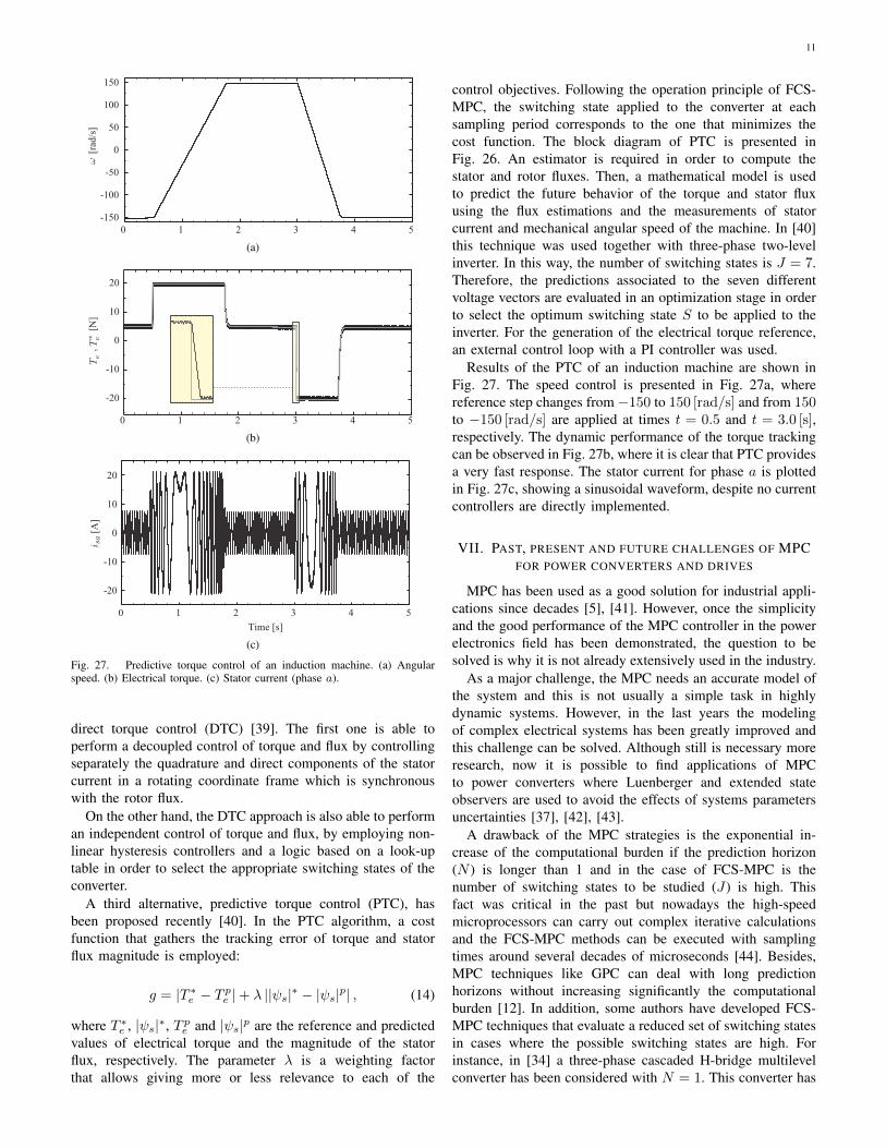
Fig. 27. Predictive torque control of an induction machine. (a) Angularspeed. (b) Electrical torque. (c) Stator current (phase a).
direct torque control (DTC) [39]. The first one is able toperform a decoupled control of torque and flux by controllingseparately the quadrature and direct components of the statorcurrent in a rotating coordinate frame which is synchronouswith the rotor flux.
On the other hand, the DTC approach is also able to performan independent control of torque and flux, by employing non-linear hysteresis controllers and a logic based on a look-uptable in order to select the appropriate switching states of theconverter.
A third alternative, predictive torque control (PTC), hasbeen proposed recently [40]. In the PTC algorithm, a costfunction that gathers the tracking error of torque and statorflux magnitude is employed:
g = |T ∗e − T pe |+ λ ||ψs|∗ − |ψs|p| , (14)
where T ∗e , |ψs|∗, T pe and |ψs|p are the reference and predicted
values of electrical torque and the magnitude of the statorflux, respectively. The parameter λ is a weighting factorthat allows giving more or less relevance to each of the
control objectives. Following the operation principle of FCS-MPC, the switching state applied to the converter at eachsampling period corresponds to the one that minimizes thecost function. The block diagram of PTC is presented inFig. 26. An estimator is required in order to compute thestator and rotor fluxes. Then, a mathematical model is usedto predict the future behavior of the torque and stator fluxusing the flux estimations and the measurements of statorcurrent and mechanical angular speed of the machine. In [40]this technique was used together with three-phase two-levelinverter. In this way, the number of switching states is J = 7.Therefore, the predictions associated to the seven differentvoltage vectors are evaluated in an optimization stage in orderto select the optimum switching state S to be applied to theinverter. For the generation of the electrical torque reference,an external control loop with a PI controller was used.
Results of the PTC of an induction machine are shown inFig. 27. The speed control is presented in Fig. 27a, wherereference step changes from −150 to 150 [rad/s] and from 150to −150 [rad/s] are applied at times t = 0.5 and t = 3.0 [s],respectively. The dynamic performance of the torque trackingcan be observed in Fig. 27b, where it is clear that PTC providesa very fast response. The stator current for phase a is plottedin Fig. 27c, showing a sinusoidal waveform, despite no currentcontrollers are directly implemented.
VII. PAST, PRESENT AND FUTURE CHALLENGES OF MPCFOR POWER CONVERTERS AND DRIVES
MPC has been used as a good solution for industrial appli-cations since decades [5], [41]. However, once the simplicityand the good performance of the MPC controller in the powerelectronics field has been demonstrated, the question to besolved is why it is not already extensively used in the industry.
As a major challenge, the MPC needs an accurate model ofthe system and this is not usually a simple task in highlydynamic systems. However, in the last years the modelingof complex electrical systems has been greatly improved andthis challenge can be solved. Although still is necessary moreresearch, now it is possible to find applications of MPCto power converters where Luenberger and extended stateobservers are used to avoid the effects of systems parametersuncertainties [37], [42], [43].
A drawback of the MPC strategies is the exponential in-crease of the computational burden if the prediction horizon(N ) is longer than 1 and in the case of FCS-MPC is thenumber of switching states to be studied (J) is high. Thisfact was critical in the past but nowadays the high-speedmicroprocessors can carry out complex iterative calculationsand the FCS-MPC methods can be executed with samplingtimes around several decades of microseconds [44]. Besides,MPC techniques like GPC can deal with long predictionhorizons without increasing significantly the computationalburden [12]. In addition, some authors have developed FCS-MPC techniques that evaluate a reduced set of switching statesin cases where the possible switching states are high. Forinstance, in [34] a three-phase cascaded H-bridge multilevelconverter has been considered with N = 1. This converter has
12
125 possible voltage vectors, but the proposed method justcalculates the cost function for the 7 vectors located aroundthe last voltage vector applied to the converter. In spite of this,finding computational efficient MPC control algorithms is anopen issue.
Usually considered an advantage, the FCS-MPC methodavoids using a modulation stage. However, this usually leads tospread harmonic spectra of the output waveforms. This can besolved taking it into account in the cost function [45] or usinga modulation stage and applying the FCS-MPC consideringall the possible combinations of the switching states of theconverter [46].
Another MPC concern is about the design of an efficientcost function and the tuning of the weighting factors. In thiscase, it can be affirmed that a systematic way to design the costfunction with the best weighting factors tuning is still missing.However, some works have introduced a first approach to solvethe problem facilitating the electrical engineers design work[47].
Finally, it should be noticed that there is a lack of analyticaltools to evaluate performance of MPC for power convertersand drives without having to carry out extensive simulationsor experiments. Therefore, it is expected that another area offuture research would be the development of such tools.
VIII. CONCLUSIONS
Model predictive control is a well-known technique toachieve a high performance operation in a wide applicationsrange. Since decades it has been successfully applied tochemical processes with low sampling requirements. However,in the last decade the academia has demonstrated that MPC canbe applied to control other systems such as electrical machinesand drives. Critical challenges as the accuracy of the models,high sampling rates and high computational cost have beenovercome due to continuous evolution of the microprocessorstechnology and the effort of the researchers. The last stepof the MPC to become mature is currently being done andsome companies have been attracted by this control method.Hopefully just one step ahead, the MPC will be extensivelyapplied to control complex electrical systems.
ACKNOWLEDGMENT
The authors gratefully acknowledge the financial supportprovided by the Andalusian Government and the EuropeanCommission (ERDF) under the project P11-TIC-7070 andthe Ministerio de Economia y Competitividad of the SpanishGovernment and the European Commission (ERDF) under theproject ENE2012-36897.
REFERENCES
[1] J. H. Lee, “Model Predictive Control: Review of the Three Decadesof Development,” International Journal of Control, Automation, andSystems, vol. 9, no. 3, pp. 415–424, 2011.
[2] M. Morari and J. H. Lee, “Model predictive control: past, present andfuture,” Computers and Chemical Engineering, vol. 23, pp. 667–682,1999.
[3] S. Kouro, P. Cortes, R. Vargas, U. Ammann, and J. Rodriguez, “ModelPredictive Control—A Simple and Powerful Method to Control PowerConverters,” IEEE Transactions on Industrial Electronics, vol. 56, no. 6,pp. 1826–1838, 2009.
[4] A. Linder, R. Kanchan, R. Kennel, and P. Stolze, Model-Based PredictiveControl of Electric Drives. Cuvillier Verlag Gottingen, 2010.
[5] J. Rodriguez and P. Cortes, Predictive control of power converters andelectrical drives, 1st ed. Wiley-IEEE Press, 2012.
[6] J. Rodriguez, M. P. Kazmierkowski, J. R. Espinoza, P. Zanchetta,H. Abu-Rub, H. A. Young, and C. A. Rojas, “State of the Art ofFinite Control Set Model Predictive Control in Power Electronics,” IEEETransactions on Industrial Informatics, vol. 9, no. 2, pp. 1003–1016,May 2013.
[7] http://ieeexplore.ieee.org/xplore/home.jsp. [Online]. Available: http://ieeexplore.ieee.org/Xplore/home.jsp
[8] E. F. Camacho and C. Bordons, Model Predictive Control. NewYork:Springer-Verlag, 1999.
[9] P. Cortes, M. P. Kazmierkowski, R. M. Kennel, D. E. Quevedo, andJ. Rodriguez, “Predictive control in power electronics and drives,”Industrial Electronics, IEEE Transactions on, vol. 55, no. 12, pp. 4312–4324, 2008.
[10] S. Mariethoz and M. Morari, “Explicit model-predictive control of apwm inverter with an lcl filter,” Industrial Electronics, IEEE Transac-tions on, vol. 56, no. 2, pp. 389–399, 2009.
[11] D. W. Clarke, C. Mohtadi, and P. S. Tuffs, “Generalized predictivecontrolpart i. the basic algorithm,” Automatica, vol. 23, no. 2, pp.137–148, Mar. 1987. [Online]. Available: http://dx.doi.org/10.1016/0005-1098(87)90087-2
[12] S. Vazquez, C. Montero, C. Bordons, and L. G. Franquelo, “Modelpredictive control of a vsi with long prediction horizon,” in IndustrialElectronics (ISIE), 2011 IEEE International Symposium on, 2011, pp.1805–1810.
[13] P. Cortes, J. Rodriguez, C. Silva, and A. Flores, “Delay Compensationin Model Predictive Current Control of a Three-Phase Inverter,” IEEETransactions on Industrial Electronics, vol. 59, no. 2, pp. 1323–1325,2012.
[14] D. E. Quevedo, R. P. Aguilera, M. A. Perez, P. Cortes, and R. Lizana,“Model predictive control of an afe rectifier with dynamic references,”Power Electronics, IEEE Transactions on, vol. 27, no. 7, pp. 3128–3136,2012.
[15] J. M. Carrasco, L. G. Franquelo, J. T. Bialasiewicz, E. Galvan, R. C. P.Guisado, M. A. M. Prats, J. I. Leon, and N. Moreno-Alfonso, “Power-electronic systems for the grid integration of renewable energy sources:A survey,” Industrial Electronics, IEEE Transactions on, vol. 53, no. 4,pp. 1002–1016, 2006.
[16] S. Vazquez, S. M. Lukic, E. Galvan, L. G. Franquelo, and J. M. Carrasco,“Energy storage systems for transport and grid applications,” IndustrialElectronics, IEEE Transactions on, vol. 57, no. 12, pp. 3881–3895, 2010.
[17] J. Dixon, L. Moran, J. Rodriguez, and R. Domke, “Reactive powercompensation technologies: State-of-the-art review,” Proceedings of theIEEE, vol. 93, no. 12, pp. 2144–2164, 2005.
[18] S. Vazquez, J. A. Sanchez, J. M. Carrasco, J. I. Leon, and E. Galvan,“A model-based direct power control for three-phase power converters,”Industrial Electronics, IEEE Transactions on, vol. 55, no. 4, pp. 1647–1657, 2008.
[19] M. Reyes, P. Rodriguez, S. Vazquez, A. Luna, R. Teodorescu, andJ. M. Carrasco, “Enhanced decoupled double synchronous referenceframe current controller for unbalanced grid-voltage conditions,” PowerElectronics, IEEE Transactions on, vol. 27, no. 9, pp. 3934–3943, 2012.
[20] P. Cortes, J. Rodriguez, P. Antoniewicz, and M. Kazmierkowski, “Directpower control of an afe using predictive control,” Power Electronics,IEEE Transactions on, vol. 23, no. 5, pp. 2516–2523, 2008.
[21] S. A. Larrinaga, M. A. R. Vidal, E. Oyarbide, and J. R. T. Apraiz,“Predictive control strategy for dc/ac converters based on direct powercontrol,” Industrial Electronics, IEEE Transactions on, vol. 54, no. 3,pp. 1261–1271, 2007.
[22] R. Aguilera, S. Vazquez, D. Quevedo, and L. G. Franquelo, “Generalizedpredictive direct power control for ac/dc converters,” in ECCE 2013 -IEEE ECCE Asia Downunder, 2013.
[23] P. Zanchetta, P. Cortes, M. Perez, J. Rodriguez, and C. Silva, “Finitestates model predictive control for shunt active filters,” in IECON 2011- 37th Annual Conference on IEEE Industrial Electronics Society, 2011,pp. 581–586.
[24] R. Vargas, J. Rodrıguez, U. Ammann, and P. W. Wheeler, “PredictiveCurrent Control of an Induction Machine Fed by a Matrix ConverterWith Reactive Power Control,” IEEE Transactions on Industrial Elec-tronics, vol. 55, no. 12, pp. 4362–4371, 2008.
[25] F. Villarroel, J. R. Espinoza, C. A. Rojas, J. Rodriguez, M. Rivera, andD. Sbarbaro, “Multiobjective Switching State Selector for Finite-StatesModel Predictive Control Based on Fuzzy Decision Making in a Matrix

13
Converter,” IEEE Transactions on Industrial Electronics, vol. 60, no. 2,pp. 589–599, Feb. 2013.
[26] M. Rivera, A. Wilson, C. A. Rojas, J. Rodriguez, J. R. Espinoza, P. W.Wheeler, and L. Empringham, “A Comparative Assessment of ModelPredictive Current Control and Space Vector Modulation in a DirectMatrix Converter,” IEEE Transactions on Industrial Electronics, vol. 60,no. 2, pp. 578–588, Feb. 2013.
[27] H. S. Patel and R. G. Hoft, “Generalized techniques of harmonicelimination and voltage control in thyristor inverters: Part i–harmonicelimination,” Industry Applications, IEEE Transactions on, vol. IA-9,no. 3, pp. 310–317, 1973.
[28] S. Kouro, B. La Rocca, P. Cortes, S. Alepuz, B. Wu, and J. Rodriguez,“Predictive control based selective harmonic elimination with lowswitching frequency for multilevel converters,” in Energy ConversionCongress and Exposition, 2009. ECCE 2009. IEEE, 2009, pp. 3130–3136.
[29] E. Jacobsen and R. Lyons, “The sliding dft,” Signal Processing Maga-zine, IEEE, vol. 20, no. 2, pp. 74–80, 2003.
[30] L. G. Franquelo, J. Napoles, R. C. P. Guisado, J. I. Leon, and M. A.Aguirre, “A flexible selective harmonic mitigation technique to meetgrid codes in three-level pwm converters,” Industrial Electronics, IEEETransactions on, vol. 54, no. 6, pp. 3022–3029, 2007.
[31] J. Napoles, J. I. Leon, R. Portillo, L. G. Franquelo, and M. A. Aguirre,“Selective harmonic mitigation technique for high-power converters,”Industrial Electronics, IEEE Transactions on, vol. 57, no. 7, pp. 2315–2323, 2010.
[32] H. Aggrawal, J. I. Leon, L. G. Franquelo, S. Kouro, P. Garg, and J. Ro-driguez, “Model predictive control based selective harmonic mitigationtechnique for multilevel cascaded h-bridge converters,” in IECON 2011- 37th Annual Conference on IEEE Industrial Electronics Society, 2011,pp. 4427–4432.
[33] R. Vargas, P. Cortes, U. Ammann, J. Rodriguez, and J. Pontt, “Predic-tive control of a three-phase neutral-point-clamped inverter,” IndustrialElectronics, IEEE Transactions on, vol. 54, no. 5, pp. 2697–2705, 2007.
[34] P. Cortes, A. Wilson, S. Kouro, J. Rodriguez, and H. Abu-Rub, “Modelpredictive control of multilevel cascaded h-bridge inverters,” IndustrialElectronics, IEEE Transactions on, vol. 57, no. 8, pp. 2691–2699, 2010.
[35] P. Lezana, R. Aguilera, and D. E. Quevedo, “Model predictive control ofan asymmetric flying capacitor converter,” Industrial Electronics, IEEETransactions on, vol. 56, no. 6, pp. 1839–1846, 2009.
[36] A. Kulka, T. Undeland, S. Vazquez, and L. G. Franquelo, “Stationaryframe voltage harmonic controller for standalone power generation,”in Power Electronics and Applications, 2007 European Conference on,2007, pp. 1–10.
[37] P. Cortes, G. Ortiz, J. I. Yuz, J. Rodriguez, S. Vazquez, and L. G.Franquelo, “Model predictive control of an inverter with output lc filterfor ups applications,” Industrial Electronics, IEEE Transactions on,vol. 56, no. 6, pp. 1875–1883, 2009.
[38] P. Cortes, J. Rodriguez, S. Vazquez, and L. G. Franquelo, “Predictivecontrol of a three-phase ups inverter using two steps prediction horizon,”in Industrial Technology (ICIT), 2010 IEEE International Conference on,2010, pp. 1283–1288.
[39] M. P. Kazmierkowski, L. G. Franquelo, J. Rodriguez, M. Perez, andJ. I. Leon, “High-performance motor drives,” Industrial ElectronicsMagazine, IEEE, vol. 5, no. 3, pp. 6–26, 2011.
[40] H. Miranda, P. Cortes, J. I. Yuz, and J. Rodriguez, “Predictive TorqueControl of Induction Machines Based on State-Space Models,” IEEETransactions on Industrial Electronics, vol. 56, no. 6, pp. 1916–1924,2009.
[41] S. Qin and T. Badgwell, “A survey of industrial model predictivecontrol technology,” Control Engineering Practice, vol. 11, no. 7,pp. 733–764, Jul. 2003. [Online]. Available: http://dx.doi.org/10.1016/s0967-0661(02)00186-7
[42] C. Xia, M. Wang, Z. Song, and T. Liu, “Robust model predictivecurrent control of three-phase voltage source pwm rectifier with onlinedisturbance observation,” Industrial Informatics, IEEE Transactions on,vol. 8, no. 3, pp. 459–471, 2012.
[43] Z. Song, C. Xia, and T. Liu, “Predictive current control of three-phasegrid-connected converters with constant switching frequency for windenergy systems,” Industrial Electronics, IEEE Transactions on, vol. 60,no. 6, pp. 2451–2464, 2013.
[44] R. K. Cavin, P. Lugli, and V. V. Zhirnov, “Science and engineeringbeyond moore’s law,” Proceedings of the IEEE, vol. 100, no. SpecialCentennial Issue, pp. 1720–1749, 2012.
[45] P. Cortes, J. Rodriguez, D. E. Quevedo, and C. Silva, “Predictive currentcontrol strategy with imposed load current spectrum,” Power Electronics,IEEE Transactions on, vol. 23, no. 2, pp. 612–618, 2008.
[46] S. Vazquez, J. I. Leon, L. G. Franquelo, J. M. Carrasco, O. Martinez,J. Rodriguez, P. Cortes, and S. Kouro, “Model predictive control withconstant switching frequency using a discrete space vector modulationwith virtual state vectors,” in Industrial Technology, 2009. ICIT 2009.IEEE International Conference on, 2009, pp. 1–6.
[47] P. Cortes, S. Kouro, B. La Rocca, R. Vargas, J. Rodriguez, J. I. Leon,S. Vazquez, and L. G. Franquelo, “Guidelines for weighting factorsdesign in model predictive control of power converters and drives,” inIndustrial Technology, 2009. ICIT 2009. IEEE International Conferenceon, 2009, pp. 1–7.