
MODEL : PP 13 SP - PowerGen · MODEL : PP 13 SP GENERATING SET ... Excellent service access further...
19
MODEL : PP 13 SP GENERATING SET PERFORMANCE 50Hz 60Hz VOLTAGE V400 PHASES Three PRIME RATED POWER 13.3kVA STANDBY RATED POWER 14.5kVA POWER FACTOR 0.80 PF FUEL USAGE @ 75% 2.8 L/hr Powered by:
Transcript of MODEL : PP 13 SP - PowerGen · MODEL : PP 13 SP GENERATING SET ... Excellent service access further...
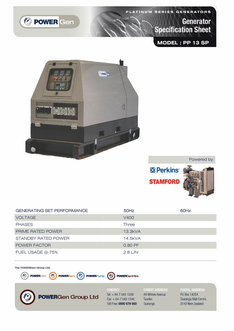
MODEL : PP 13 SP
GENERATING SET PERFORMANCE 50Hz 60Hz
VOLTAGE V400
PHASES Three
PRIME RATED POWER 13.3kVA
STANDBY RATED POWER 14.5kVA
POWER FACTOR 0.80 PF
FUEL USAGE @ 75% 2.8 L/hr
Powered by:

PERFORMANCE 50Hz 60Hz
BASELOAD RATED POWER TBA
PRIME RATED POWER 12.0KWm
STANDBY RATED POWER 13.3KWm
FUEL CONSUMPTION 254g/KWh @ 100% 258g/KWh @ 75% 291g/KWh @ 50%
TYPE Diesel 4 stroke
ASPIRATION Naturally aspirated
INJECTION TYPE Indirect injection
ENGINE GOVERNOR Mechanical governor
CYLINDERS AND ARRANGEMENT Three in line
BORE AND STROKE 84mm x 90mm
COMPRESSION RATIO 22.5 : 1
ELECTRICAL SYSTEM VOLTAGE 12 volt
BATTERY TYPE Lead acid, 12V
DERATING FOR TEMPERATURE 40 deg C
DERATING FOR ALTITUDE 1000m
ENGINE PERKINS 403C-15G
DERATING FOR HUMIDITY 90%
Murphy EL150K water level sensor to constantly monitor the radiator water level. It will put the generator into shut down in event of loss of coolant regardless of if the unit is running or not.
Powered by a world renowned Perkins Engine backed by a world wide OEM warranty.
Water jacket heater to keep the engine at optimum temperature whilst in standby. Configured to sense water temperature whilst stationary and provide an alarm in event of a failure of the heater.
ENGINE

PERFORMANCE 50Hz 60Hz
MODEL PI144D
BASELOAD RATED POWER 40 deg C 18.2kVA
PRIME RATED POWER 40 deg C 20.0kVA
STANDBY RATED POWER 40 deg C 21.5kVA
STANDBY RATED POWER 27 deg C 22.0kVA
EFFICIENCY 85%
STANDARD WING CONNECTIONS Star Delta
EXCITER Self excited
POLES 4 poles
PHASES Three phases
WIRES 12 leads
VOLTAGE REGULATION +/- 1.5%
INSULATION CLASS Class H
ENCLOSURE IP23
MAXIMUM OVERSPEED 150%
STANDARD AVR MODEL MX341
OPTIONAL AVR MODEL MX321
DERATING FOR TEMPERATURE 40 deg C
DERATING FOR ALTITUDE 1000mm
ALTERNATOR STAMFORD
Electrical power is generated using the well recognised Stamford Newage alternator.
Anti condensation heater to keep the alternator windings at optimum temperature whilst the generator is in standby.
Permanent Magnet Generator separate excitation system to offer optimum load response and durability to unbalanced or highly harmonic load types.
ALTERNATOR
GENERATOR EQUIPMENT
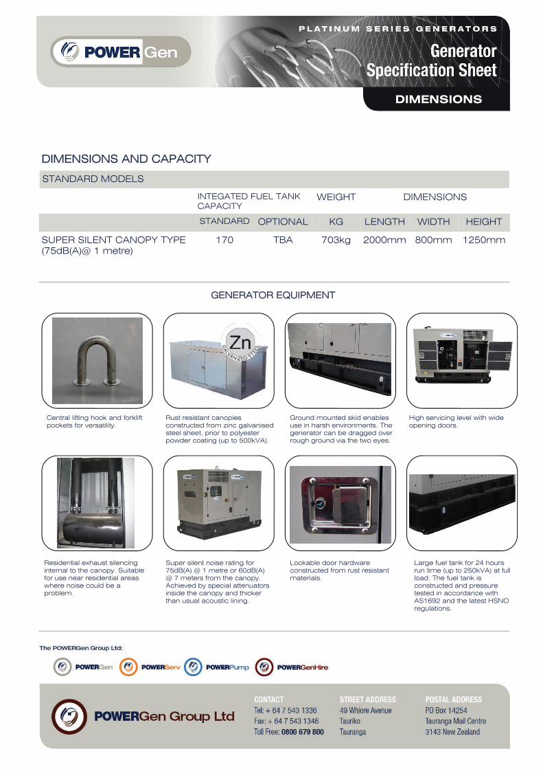
DIMENSIONS AND CAPACITY
STANDARD MODELS
INTEGATED FUEL TANK CAPACITY
WEIGHT
STANDARD OPTIONAL KG LENGTH WIDTH HEIGHT
SUPER SILENT CANOPY TYPE (75dB(A)@ 1 metre)
170 TBA 703kg 2000mm 800mm 1250mm
DIMENSIONS
Central lifting hook and forklift pockets for versatility.
Rust resistant canopies constructed from zinc galvanised steel sheet, prior to polyester powder coating (up to 500kVA).
Ground mounted skid enables use in harsh environments. The generator can be dragged over rough ground via the two eyes.
High servicing level with wide opening doors.
Residential exhaust silencing internal to the canopy. Suitable for use near residential areas where noise could be a problem.
Super silent noise rating for 75dB(A) @ 1 metre or 60dB(A) @ 7 meters from the canopy. Achieved by special attenuators inside the canopy and thicker than usual acoustic lining.
Lockable door hardware constructed from rust resistant materials.
Large fuel tank for 24 hours run time (up to 250kVA) at full load. The fuel tank is constructed and pressure tested in accordance with AS1692 and the latest HSNO regulations.
DIMENSIONS

AUTOMATIC MODELS – EQUIPMENT
4 poles ABB circuit breaker, electronic control unit ComAp AMF25-NT control panel box key, emergency stop button, water jacket heater, battery charger, anti condensation heater.
AUTOMATIC MODELS – PROTECTORS
Low oil pressure, low fuel level, overload, over/ under frequency, low voltage, over/ under battery voltage, belt breakage.
AUTOMATIC MODELS – INSTRUMENTATION
Voltmeter, ammeter (3 phases), frequency meter, hour meter, battery voltage, fuel level.
Dedicated battery charger with boost and flat modes. Battery charger is configured to provide an alarm in event of a fault with the charging system.
Wiring and protection in accordance with AS3000 and AS3010. Robust, clear labelling system with comprehensive schematic drawings.
Option of a high spec controller capable of synchronising with other generators or the mains supply. Standard controller can be used in key start or standard AMF mode.
Battery isolator to enable the battery to be switched off in the event of the generator being put into storage for extended periods.
Range of standard New Zealand series 56 single phase and three phase sockets on units up to 150kVA. Additional sockets available on request.
CONTROLLER
Four pole MCCB in accordance with AS3010. The motorised MCCB is fitted with a stunt trip to protect the generator in event of a sudden shutdown.
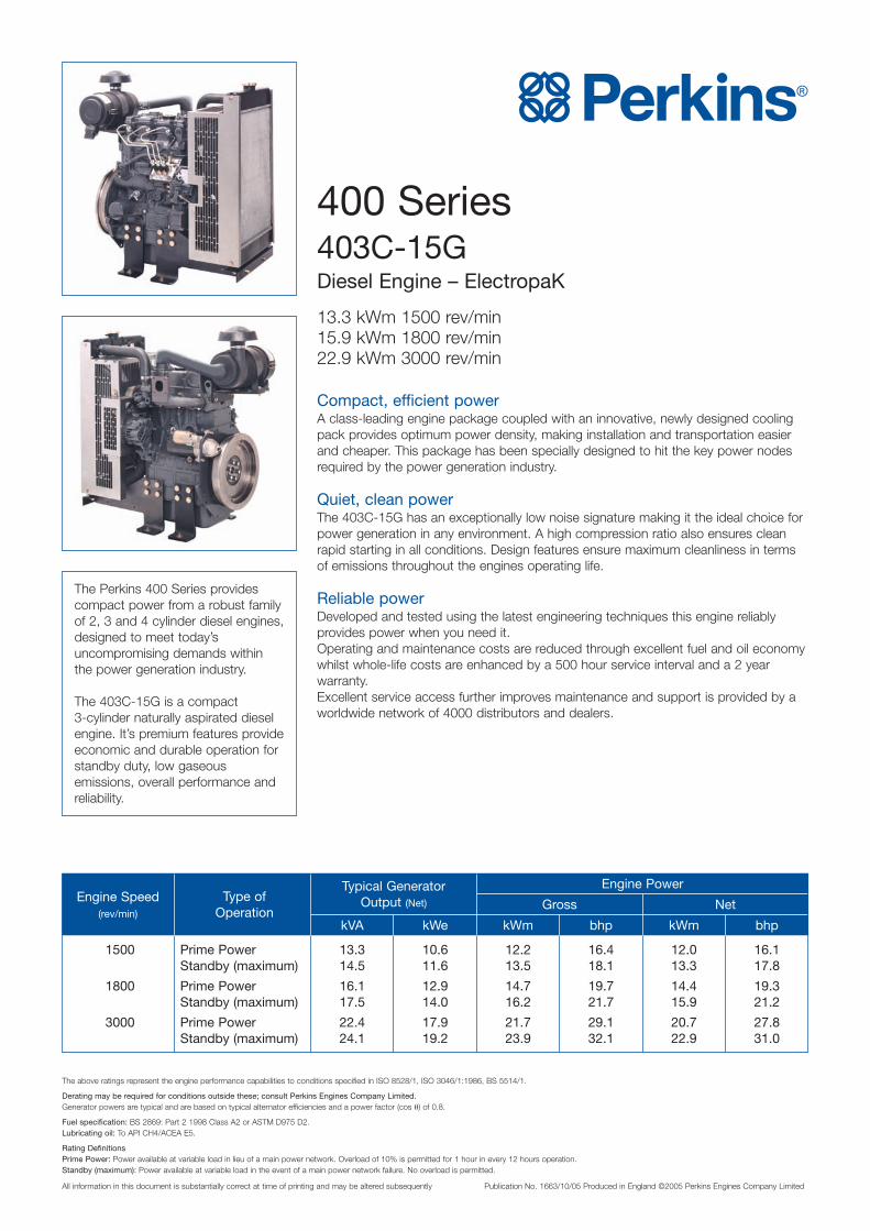
400 Series403C-15GDiesel Engine – ElectropaK
13.3 kWm 1500 rev/min15.9 kWm 1800 rev/min22.9 kWm 3000 rev/min
Compact, efficient powerA class-leading engine package coupled with an innovative, newly designed coolingpack provides optimum power density, making installation and transportation easierand cheaper. This package has been specially designed to hit the key power nodesrequired by the power generation industry.
Quiet, clean powerThe 403C-15G has an exceptionally low noise signature making it the ideal choice forpower generation in any environment. A high compression ratio also ensures cleanrapid starting in all conditions. Design features ensure maximum cleanliness in termsof emissions throughout the engines operating life.
Reliable powerDeveloped and tested using the latest engineering techniques this engine reliablyprovides power when you need it.Operating and maintenance costs are reduced through excellent fuel and oil economywhilst whole-life costs are enhanced by a 500 hour service interval and a 2 yearwarranty.Excellent service access further improves maintenance and support is provided by aworldwide network of 4000 distributors and dealers.
The Perkins 400 Series providescompact power from a robust familyof 2, 3 and 4 cylinder diesel engines,designed to meet today’suncompromising demands withinthe power generation industry.
The 403C-15G is a compact3-cylinder naturally aspirated dieselengine. It’s premium features provideeconomic and durable operation forstandby duty, low gaseousemissions, overall performance andreliability.
The above ratings represent the engine performance capabilities to conditions specified in ISO 8528/1, ISO 3046/1:1986, BS 5514/1.
Derating may be required for conditions outside these; consult Perkins Engines Company Limited.Generator powers are typical and are based on typical alternator efficiencies and a power factor (cos θ) of 0.8.
Fuel specification: BS 2869: Part 2 1998 Class A2 or ASTM D975 D2.Lubricating oil: To API CH4/ACEA E5.
Rating DefinitionsPrime Power: Power available at variable load in lieu of a main power network. Overload of 10% is permitted for 1 hour in every 12 hours operation.Standby (maximum): Power available at variable load in the event of a main power network failure. No overload is permitted.
All information in this document is substantially correct at time of printing and may be altered subsequently Publication No. 1663/10/05 Produced in England ©2005 Perkins Engines Company Limited
Engine Speed(rev/min)
Type ofOperation
kVA kWe kWm bhp kWm bhp
Gross Net
Engine PowerTypical GeneratorOutput (Net)
1500 Prime Power 13.3 10.6 12.2 16.4 12.0 16.1Standby (maximum) 14.5 11.6 13.5 18.1 13.3 17.8
1800 Prime Power 16.1 12.9 14.7 19.7 14.4 19.3Standby (maximum) 17.5 14.0 16.2 21.7 15.9 21.2
3000 Prime Power 22.4 17.9 21.7 29.1 20.7 27.8Standby (maximum) 24.1 19.2 23.9 32.1 22.9 31.0

691 mm
791 mm
476 mm820 mm
Perkins Engines Company LimitedPeterborough PE1 5NAUnited KingdomTelephone +44 (0)1733 583000Fax +44 (0)1733 582240www.perkins.com
All information in this document is substantially correct at time of printing and may be altered subsequentlyPublication No. 1663/10/05 Produced in England ©2005 Perkins Engines Company Limited
Standard ElectropaK Specification
Air inlet� Mounted air filter
Fuel system� Mechanically governed cassette type fuel injection pump� Split element fuel filter
Lubrication system� Wet steel sump with filler and dipstick� Spin-on full-flow lub oil filter
Cooling system� Thermostatically-controlled system with belt driven circulating pump
and pusher fan� Mounted radiator piping and guards
Electrical equipment� 12 volt starter motor and 12 volt 55 amp alternator with DC output� Oil pressure and coolant temperature switches � 12 volt shut off solenoid energised to run � Glow plug cold start aid and heater/starter switch
Flywheel and housing1500/1800 rev/min� High inertia flywheel to SAE J620 Size 71⁄2 Heavy � Flywheel housing SAE 4 Long3000/3600 rev/min� High inertia flywheel to SAE J620 Size 71⁄2 Light� Flywheel housing SAE 4 Short
Mountings� Front and rear engine mounting bracket
Literature� User’s Handbook
Optional Equipment� Exhaust silencer� Workshop manual� Parts book
Distributed by
400 Series403C-15G
General DataNumber of cylinders 3Cylinder arrangement Vertical in-lineCycle 4 strokeInduction system Natural aspirationCombustion system Indirect injectionCooling system Water-cooledBore and stroke 84 x 90 mmDisplacement 1496ccCompression ratio 22.5:1Direction of rotation Anti-clockwise
viewed on flywheelTotal coolant capacity 5.98 litresLength 820 mmWidth 476 mmHeight 791 mmDry weight (engine) 197 kg
(1500/1800 rev/min)175 kg(3000/3600 rev/min)
Final weight and dimensions will depend on completed specification.
Fuel Consumption
1500 rev/min 1800 rev/min 3000 rev/minEngine Speed
g/kWh l/hr g/kWh l/hr g/kWh l/hr
At Standby Power 258 4.1 249 4.8 264 7.5
At Prime Power 254 3.7 247 4.3 264 6.8
At 75% of Prime Power 258 2.8 249 3.3 284 5.5
At 50% of Prime Power 291 2.1 275 2.4 338 4.4

AP
PR
OV
ED
DO
CU
ME
NT
PI144D - Winding 311
Technical Data Sheet
AP
PR
OV
ED
DO
CU
ME
NT
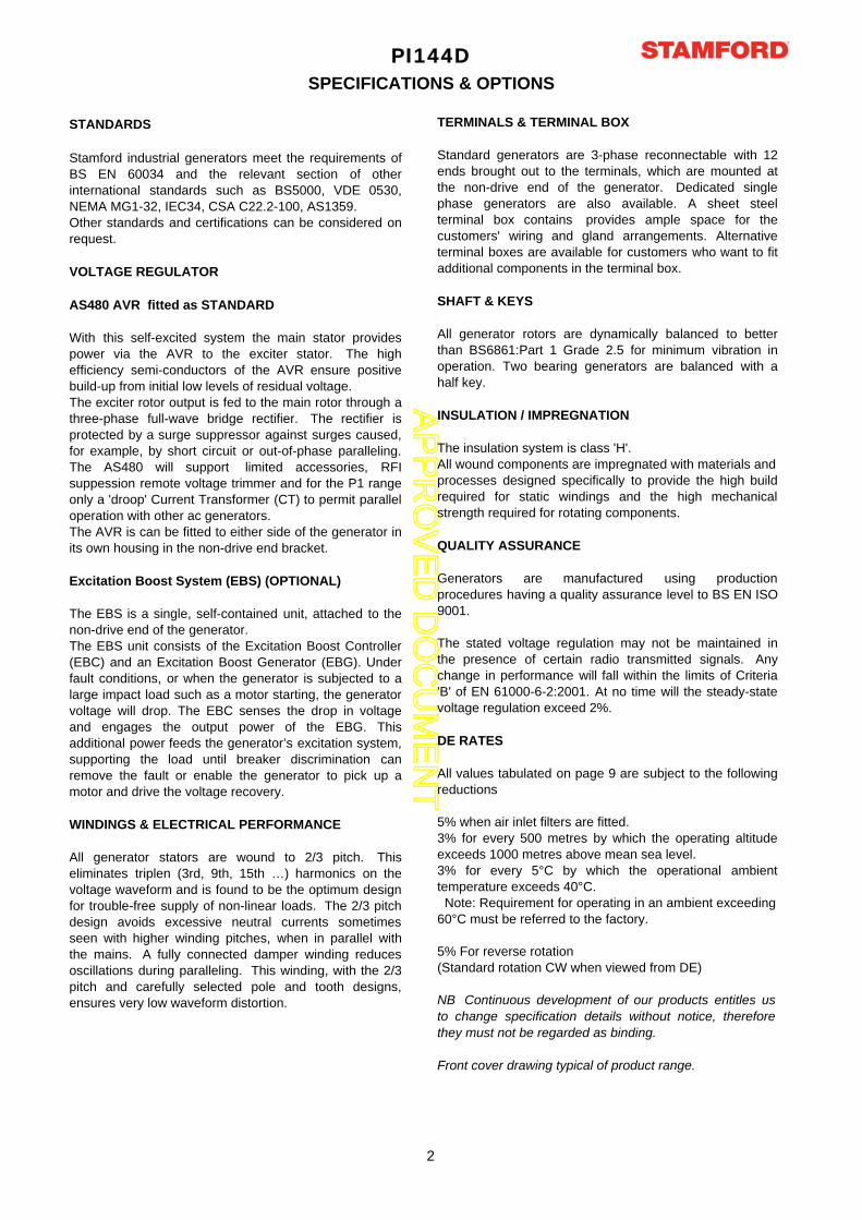
PI144DSPECIFICATIONS & OPTIONS
STANDARDS
Stamford industrial generators meet the requirements ofBS EN 60034 and the relevant section of otherinternational standards such as BS5000, VDE 0530,NEMA MG1-32, IEC34, CSA C22.2-100, AS1359.Other standards and certifications can be considered onrequest.
VOLTAGE REGULATOR
AS480 AVR fitted as STANDARD
With this self-excited system the main stator providespower via the AVR to the exciter stator. The highefficiency semi-conductors of the AVR ensure positivebuild-up from initial low levels of residual voltage.The exciter rotor output is fed to the main rotor through athree-phase full-wave bridge rectifier. The rectifier isprotected by a surge suppressor against surges caused,for example, by short circuit or out-of-phase paralleling.The AS480 will support limited accessories, RFIsuppession remote voltage trimmer and for the P1 rangeonly a 'droop' Current Transformer (CT) to permit paralleloperation with other ac generators.The AVR is can be fitted to either side of the generator inits own housing in the non-drive end bracket.
Excitation Boost System (EBS) (OPTIONAL)
The EBS is a single, self-contained unit, attached to thenon-drive end of the generator.The EBS unit consists of the Excitation Boost Controller(EBC) and an Excitation Boost Generator (EBG). Underfault conditions, or when the generator is subjected to alarge impact load such as a motor starting, the generatorvoltage will drop. The EBC senses the drop in voltageand engages the output power of the EBG. Thisadditional power feeds the generator’s excitation system,supporting the load until breaker discrimination canremove the fault or enable the generator to pick up amotor and drive the voltage recovery.
WINDINGS & ELECTRICAL PERFORMANCE
All generator stators are wound to 2/3 pitch. Thiseliminates triplen (3rd, 9th, 15th …) harmonics on thevoltage waveform and is found to be the optimum designfor trouble-free supply of non-linear loads. The 2/3 pitchdesign avoids excessive neutral currents sometimesseen with higher winding pitches, when in parallel withthe mains. A fully connected damper winding reducesoscillations during paralleling. This winding, with the 2/3pitch and carefully selected pole and tooth designs,ensures very low waveform distortion.
TERMINALS & TERMINAL BOX
Standard generators are 3-phase reconnectable with 12ends brought out to the terminals, which are mounted atthe non-drive end of the generator. Dedicated singlephase generators are also available. A sheet steelterminal box contains provides ample space for thecustomers' wiring and gland arrangements. Alternativeterminal boxes are available for customers who want to fitadditional components in the terminal box.
SHAFT & KEYS
All generator rotors are dynamically balanced to betterthan BS6861:Part 1 Grade 2.5 for minimum vibration inoperation. Two bearing generators are balanced with ahalf key.
INSULATION / IMPREGNATION
The insulation system is class 'H'.All wound components are impregnated with materials and processes designed specifically to provide the high buildrequired for static windings and the high mechanicalstrength required for rotating components.
QUALITY ASSURANCE
Generators are manufactured using productionprocedures having a quality assurance level to BS EN ISO9001.
The stated voltage regulation may not be maintained inthe presence of certain radio transmitted signals. Anychange in performance will fall within the limits of Criteria'B' of EN 61000-6-2:2001. At no time will the steady-statevoltage regulation exceed 2%.
DE RATES
All values tabulated on page 9 are subject to the followingreductions
5% when air inlet filters are fitted.3% for every 500 metres by which the operating altitudeexceeds 1000 metres above mean sea level.3% for every 5°C by which the operational ambienttemperature exceeds 40°C. Note: Requirement for operating in an ambient exceeding 60°C must be referred to the factory.
5% For reverse rotation(Standard rotation CW when viewed from DE)
NB Continuous development of our products entitles usto change specification details without notice, thereforethey must not be regarded as binding.
Front cover drawing typical of product range.
2
AP
PR
OV
ED
DO
CU
ME
NT
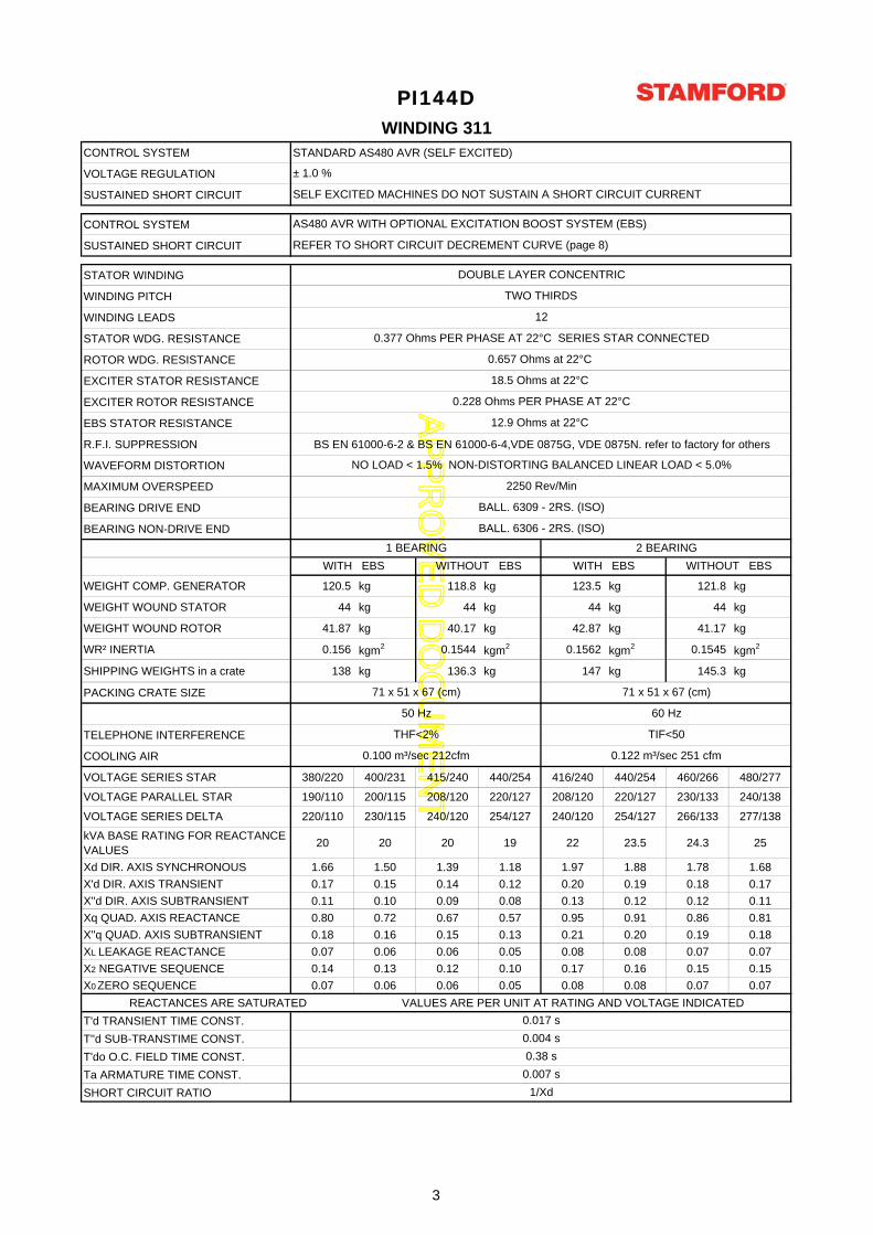
CONTROL SYSTEM STANDARD AS480 AVR (SELF EXCITED)
VOLTAGE REGULATION
SUSTAINED SHORT CIRCUIT
CONTROL SYSTEM
SUSTAINED SHORT CIRCUIT
STATOR WINDING
WINDING PITCH
WINDING LEADS
STATOR WDG. RESISTANCE
ROTOR WDG. RESISTANCE
EXCITER STATOR RESISTANCE
EXCITER ROTOR RESISTANCE
EBS STATOR RESISTANCE
R.F.I. SUPPRESSION BS EN 61000-6-2 & BS EN 61000-6-4,VDE 0875G, VDE 0875N. refer to factory for others
WAVEFORM DISTORTION
MAXIMUM OVERSPEED
BEARING DRIVE END
BEARING NON-DRIVE END
WEIGHT COMP. GENERATOR 120.5 kg 118.8 kg 123.5 kg 121.8 kg
WEIGHT WOUND STATOR 44 kg 44 kg 44 kg 44 kg
WEIGHT WOUND ROTOR 41.87 kg 40.17 kg 42.87 kg 41.17 kg
WR² INERTIA 0.156 kgm2 0.1544 kgm2 0.1562 kgm2 0.1545 kgm2
SHIPPING WEIGHTS in a crate 138 kg 136.3 kg 147 kg 145.3 kg
PACKING CRATE SIZE
TELEPHONE INTERFERENCE
COOLING AIR
VOLTAGE SERIES STAR 380/220 400/231 415/240 440/254 416/240 440/254 460/266 480/277
VOLTAGE PARALLEL STAR 190/110 200/115 208/120 220/127 208/120 220/127 230/133 240/138
VOLTAGE SERIES DELTA 220/110 230/115 240/120 254/127 240/120 254/127 266/133 277/138
kVA BASE RATING FOR REACTANCE
VALUES20 20 20 19 22 23.5 24.3 25
Xd DIR. AXIS SYNCHRONOUS 1.66 1.50 1.39 1.18 1.97 1.88 1.78 1.68
X'd DIR. AXIS TRANSIENT 0.17 0.15 0.14 0.12 0.20 0.19 0.18 0.17
X''d DIR. AXIS SUBTRANSIENT 0.11 0.10 0.09 0.08 0.13 0.12 0.12 0.11
Xq QUAD. AXIS REACTANCE 0.80 0.72 0.67 0.57 0.95 0.91 0.86 0.81
X''q QUAD. AXIS SUBTRANSIENT 0.18 0.16 0.15 0.13 0.21 0.20 0.19 0.18
XL LEAKAGE REACTANCE 0.07 0.06 0.06 0.05 0.08 0.08 0.07 0.07
X2 NEGATIVE SEQUENCE 0.14 0.13 0.12 0.10 0.17 0.16 0.15 0.15
X0 ZERO SEQUENCE 0.07 0.06 0.06 0.05 0.08 0.08 0.07 0.07
REACTANCES ARE SATURATED VALUES ARE PER UNIT AT RATING AND VOLTAGE INDICATED
T'd TRANSIENT TIME CONST.
T''d SUB-TRANSTIME CONST.
T'do O.C. FIELD TIME CONST.
Ta ARMATURE TIME CONST.
SHORT CIRCUIT RATIO
71 x 51 x 67 (cm)
WINDING 311
71 x 51 x 67 (cm)
0.377 Ohms PER PHASE AT 22°C SERIES STAR CONNECTED
1 BEARING
± 1.0 %
AS480 AVR WITH OPTIONAL EXCITATION BOOST SYSTEM (EBS)
SELF EXCITED MACHINES DO NOT SUSTAIN A SHORT CIRCUIT CURRENT
0.100 m³/sec 212cfm 0.122 m³/sec 251 cfm
50 Hz
THF<2%
60 Hz
TIF<50
PI144D
0.657 Ohms at 22°C
12.9 Ohms at 22°C
18.5 Ohms at 22°C
1/Xd
0.017 s
0.004 s
0.38 s
0.007 s
2 BEARING
2250 Rev/Min
12
REFER TO SHORT CIRCUIT DECREMENT CURVE (page 8)
DOUBLE LAYER CONCENTRIC
NO LOAD < 1.5% NON-DISTORTING BALANCED LINEAR LOAD < 5.0%
BALL. 6306 - 2RS. (ISO)
0.228 Ohms PER PHASE AT 22°C
TWO THIRDS
BALL. 6309 - 2RS. (ISO)
WITH EBS WITHOUT EBS WITH EBS WITHOUT EBS
3
AP
PR
OV
ED
DO
CU
ME
NT
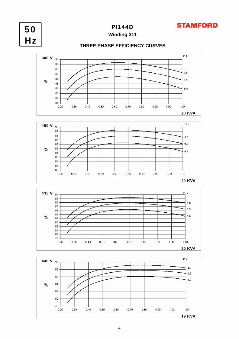
Winding 311PI144D
THREE PHASE EFFICIENCY CURVES
50Hz
4

AP
PR
OV
ED
DO
CU
ME
NT
PI144DWinding 311
Locked Rotor Motor Starting CurvesAS480 AVR Without EBS
346V 380V 400V 415V 440V
0
5
10
15
20
25
30
0 5 10 15 20 25 30 35 40LOCKED ROTOR kVA
PER
CEN
T TR
AN
SIEN
T VO
LTA
GE
DIP
.
380V 416V 440V 460V 480V
0
5
10
15
20
25
30
0 5 10 15 20 25 30 35 40 45 50 55LOCKED ROTOR kVA
PER
CEN
T TR
AN
SIEN
T VO
LTA
GE
DIP
.
60Hz
50Hz
6

AP
PR
OV
ED
DO
CU
ME
NT
PI144DWinding 311
Locked Rotor Motor Starting CurvesAS480 AVR With EBS fitted
346V 380V 400V 415V 440V
0
5
10
15
20
25
30
0 5 10 15 20 25 30 35 40 45LOCKED ROTOR kVA
PER
CEN
T TR
AN
SIEN
T VO
LTA
GE
DIP
.
380V 416V 440V 460V 480V
0
5
10
15
20
25
30
0 10 20 30 40 50 60LOCKED ROTOR kVA
PER
CEN
T TR
AN
SIEN
T VO
LTA
GE
DIP
.
50Hz
60Hz
7
AP
PR
OV
ED
DO
CU
ME
NT
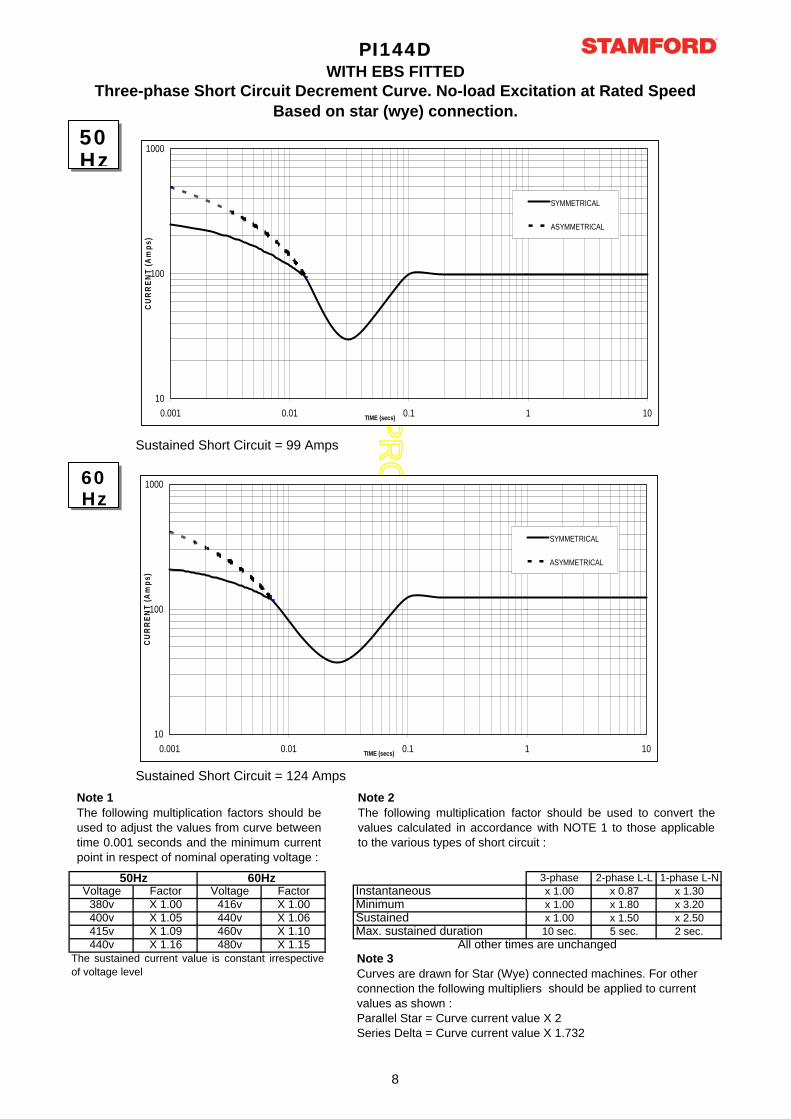
3-phase 2-phase L-L 1-phase L-NVoltage Factor Voltage Factor x 1.00 x 0.87 x 1.30
380v X 1.00 416v X 1.00 x 1.00 x 1.80 x 3.20400v X 1.05 440v X 1.06 x 1.00 x 1.50 x 2.50415v X 1.09 460v X 1.10 10 sec. 5 sec. 2 sec.440v X 1.16 480v X 1.15
PI144D
50Hz 60Hz
WITH EBS FITTED
The sustained current value is constant irrespective
of voltage level
Three-phase Short Circuit Decrement Curve. No-load Excitation at Rated SpeedBased on star (wye) connection.
Max. sustained durationAll other times are unchanged
Instantaneous
SustainedMinimum
Sustained Short Circuit = 99 Amps
Sustained Short Circuit = 124 Amps
Note 1The following multiplication factors should beused to adjust the values from curve betweentime 0.001 seconds and the minimum currentpoint in respect of nominal operating voltage :
Note 2The following multiplication factor should be used to convert thevalues calculated in accordance with NOTE 1 to those applicableto the various types of short circuit :
50Hz
60Hz
Note 3Curves are drawn for Star (Wye) connected machines. For other connection the following multipliers should be applied to current values as shown : Parallel Star = Curve current value X 2Series Delta = Curve current value X 1.732
10
100
1000
0.001 0.01 0.1 1 10TIME (secs)
CU
RR
ENT
(Am
ps)
SYMMETRICAL
ASYMMETRICAL
10
100
1000
0.001 0.01 0.1 1 10TIME (secs)
CU
RR
ENT
(Am
ps)
SYMMETRICAL
ASYMMETRICAL
8
AP
PR
OV
ED
DO
CU
ME
NT
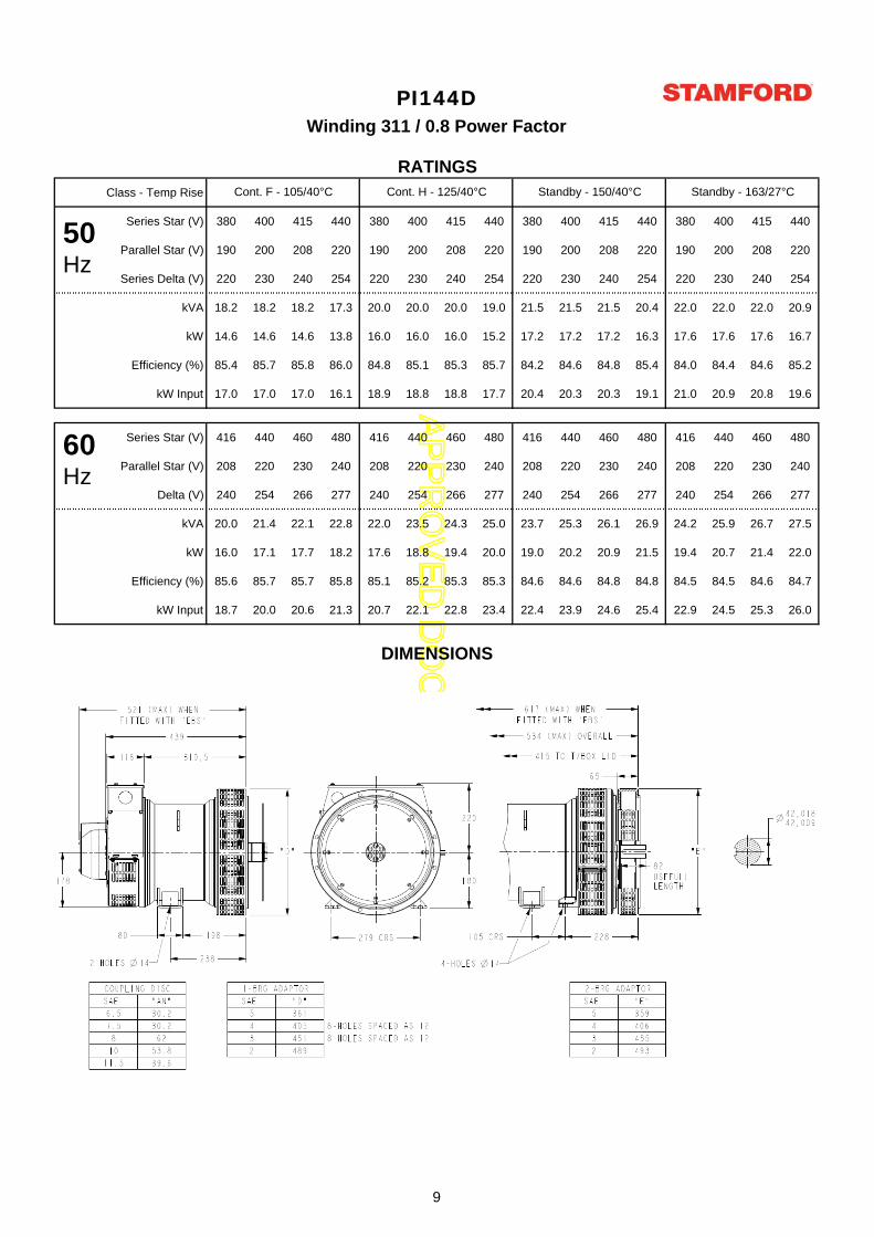
Class - Temp Rise
Series Star (V) 380 400 415 440 380 400 415 440 380 400 415 440 380 400 415 440
Parallel Star (V) 190 200 208 220 190 200 208 220 190 200 208 220 190 200 208 220
Series Delta (V) 220 230 240 254 220 230 240 254 220 230 240 254 220 230 240 254
kVA 18.2 18.2 18.2 17.3 20.0 20.0 20.0 19.0 21.5 21.5 21.5 20.4 22.0 22.0 22.0 20.9
kW 14.6 14.6 14.6 13.8 16.0 16.0 16.0 15.2 17.2 17.2 17.2 16.3 17.6 17.6 17.6 16.7
Efficiency (%) 85.4 85.7 85.8 86.0 84.8 85.1 85.3 85.7 84.2 84.6 84.8 85.4 84.0 84.4 84.6 85.2
kW Input 17.0 17.0 17.0 16.1 18.9 18.8 18.8 17.7 20.4 20.3 20.3 19.1 21.0 20.9 20.8 19.6
Series Star (V) 416 440 460 480 416 440 460 480 416 440 460 480 416 440 460 480
Parallel Star (V) 208 220 230 240 208 220 230 240 208 220 230 240 208 220 230 240
Delta (V) 240 254 266 277 240 254 266 277 240 254 266 277 240 254 266 277
kVA 20.0 21.4 22.1 22.8 22.0 23.5 24.3 25.0 23.7 25.3 26.1 26.9 24.2 25.9 26.7 27.5
kW 16.0 17.1 17.7 18.2 17.6 18.8 19.4 20.0 19.0 20.2 20.9 21.5 19.4 20.7 21.4 22.0
Efficiency (%) 85.6 85.7 85.7 85.8 85.1 85.2 85.3 85.3 84.6 84.6 84.8 84.8 84.5 84.5 84.6 84.7
kW Input 18.7 20.0 20.6 21.3 20.7 22.1 22.8 23.4 22.4 23.9 24.6 25.4 22.9 24.5 25.3 26.0
DIMENSIONS
PI144DWinding 311 / 0.8 Power Factor
RATINGSCont. F - 105/40°C Cont. H - 125/40°C Standby - 150/40°C Standby - 163/27°C
50Hz
60Hz
9
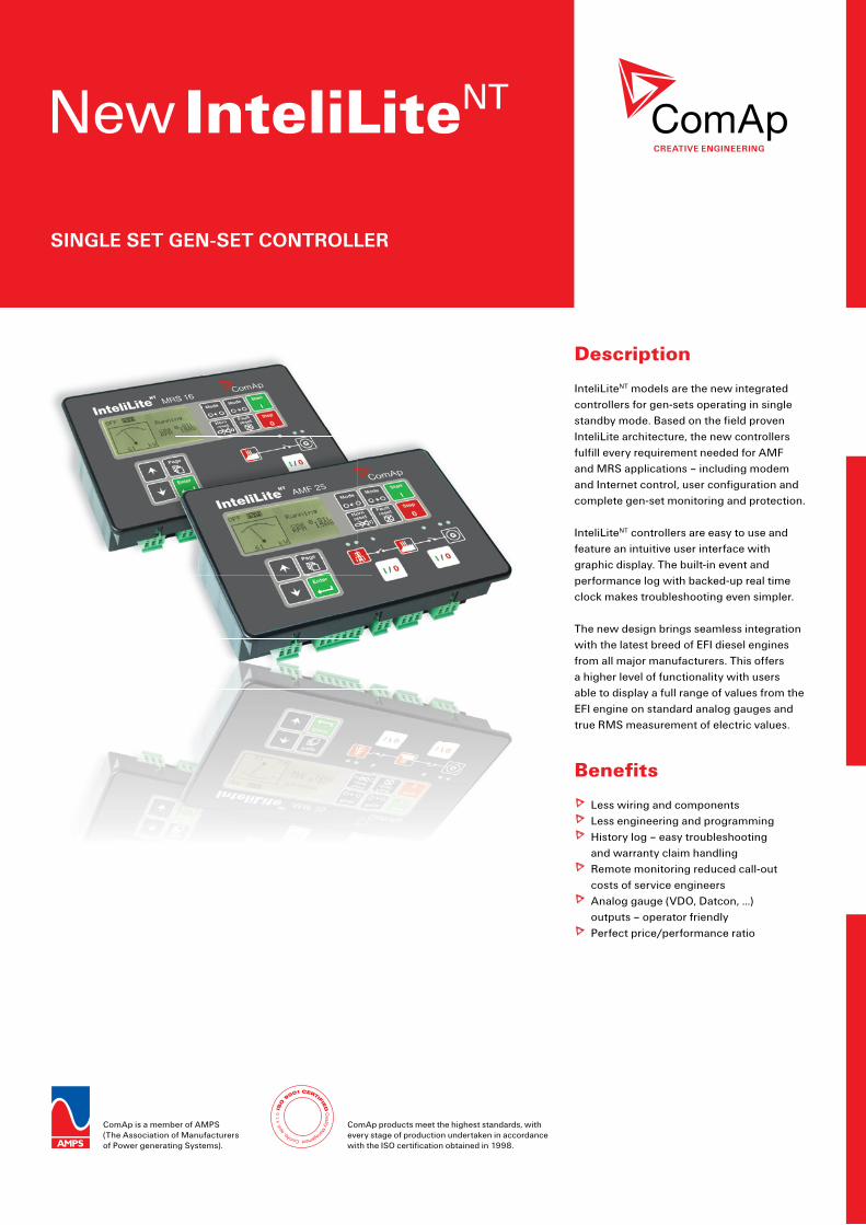
New InteliLiteNT
SINGLE SET GEN-SET CONTROLLER
CREATIVE ENGINEERING
ComAp is a member of AMPS(The Association of Manufacturers of Power generating Systems).
ComAp products meet the highest standards, with every stage of production undertaken in accordance with the ISO certification obtained in 1998.
Description
InteliLiteNT models are the new integrated controllers for gen-sets operating in single standby mode. Based on the field proven InteliLite architecture, the new controllers fulfill every requirement needed for AMF and MRS applications – including modem and Internet control, user configuration and complete gen-set monitoring and protection.
InteliLiteNT controllers are easy to use and feature an intuitive user interface with graphic display. The built-in event and performance log with backed-up real time clock makes troubleshooting even simpler.
The new design brings seamless integration with the latest breed of EFI diesel engines from all major manufacturers. This offers a higher level of functionality with users able to display a full range of values from the EFI engine on standard analog gauges and true RMS measurement of electric values.
Benefits
Less wiring and componentsLess engineering and programmingHistory log – easy troubleshooting and warranty claim handlingRemote monitoring reduced call-out costs of service engineersAnalog gauge (VDO, Datcon, …) outputs – operator friendlyPerfect price/performance ratio
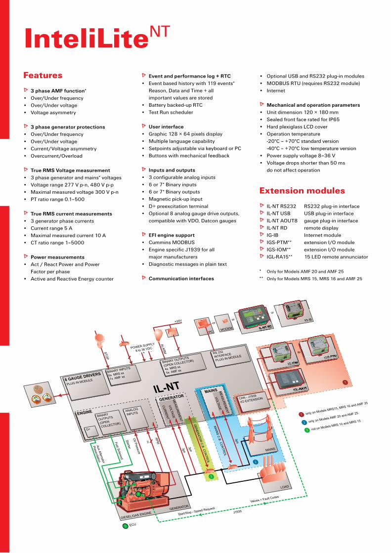
Features
3 phase AMF function* Over/Under frequencyOver/Under voltageVoltage asymmetry
3 phase generator protectionsOver/Under frequencyOver/Under voltageCurrent/Voltage asymmetryOvercurrent/Overload
True RMS Voltage measurement3 phase generator and mains* voltagesVoltage range 277 V p-n, 480 V p-p Maximal measured voltage 300 V p-nPT ratio range 0.1–500
True RMS current measurements3 generator phase currentsCurrent range 5 AMaximal measured current 10 ACT ratio range 1–5000
Power measurementsAct / React Power and Power Factor per phaseActive and Reactive Energy counter
•••
••••
••••
••••
•
•
InteliLiteNT
Event and performance log + RTCEvent based history with 119 events* Reason, Data and Time + all important values are storedBattery backed-up RTCTest Run scheduler
User interfaceGraphic 128 × 64 pixels displayMultiple language capabilitySetpoints adjustable via keyboard or PCButtons with mechanical feedback
Inputs and outputs3 configurable analog inputs6 or 7* Binary inputs6 or 7* Binary outputsMagnetic pick-up inputD+ preexcitation terminal Optional 8 analog gauge drive outputs, compatible with VDO, Datcon gauges
EFI engine supportCummins MODBUSEngine specific J1939 for all major manufacturersDiagnostic messages in plain text
Communication interfaces
•
••
••••
••••••
••
•
Optional USB and RS232 plug-in modulesMODBUS RTU (requires RS232 module)Internet
Mechanical and operation parametersUnit dimension 120 × 180 mmSealed front face rated for IP65Hard plexiglass LCD coverOperation temperature -20°C – +70°C standard version -40°C – +70°C low temperature versionPower supply voltage 8–36 VVoltage drops shorter than 50 ms do not affect operation
Extension modules
IL-NT RS232 RS232 plug-in interfaceIL-NT USB USB plug-in interfaceIL-NT AOUT8 gauge plug-in interfaceIL-NT RD remote display IG-IB Internet moduleIGS-PTM** extension I/O moduleIGS-IOM** extension I/O moduleIGL-RA15** 15 LED remote annunciator
* Only for Models AMF 20 and AMF 25
** Only for Models MRS 15, MRS 16 and AMF 25
•••
••••
••
IG-IB
PC MODEM
+24V
IL-NT RDor
or
STOP
ALARM
or
GENERATOR
DIESEL/GAS ENGINE
1
ENGINE ANALOG
INPUTS
IL-NT
POWER SUPPLY
8 to 36 VDC+ -
BINARY INPUTS
6x MRS xx
7x AMF xx
BINARY OUTPUTS
(OPEN COLLECTOR)
4x MRS xx
5x AMF xx
RS 232INTERFACE
PLUG IN MODULE
BINARYOUTPUTS
(OPENCOLLECTOR)
D+
Oil Pressure
RPM
J1939
1
1 ECU
Start/Stop - Speed Request
Values + Fault Codes
Aux Alternator
Preexcitation
Fuel Solenoid
Starter
2
GENERATOR
CURRENTVO
LTAGE
MEASUREM
ENT
3
8 GAUGE DRIVERS
PLUG IN MODULE
IGL-RA15
IGS-PTM
IG-IOM
or
CAN - J1939
I/O EXTENSION
1
°C
LOAD
3ph
3phG
ENERATOR C.B. CO
NTROL
MAINS C.B. CO
NTROL
3ph
MAINS
MAINS
VOLTAG
EM
EASUREMENT
2
3
2
1 only on Models MRS15, MRS 16 and AMF 25
only on Models AMF 20 and AMF 25
not on Models MRS 10 and MRS 15
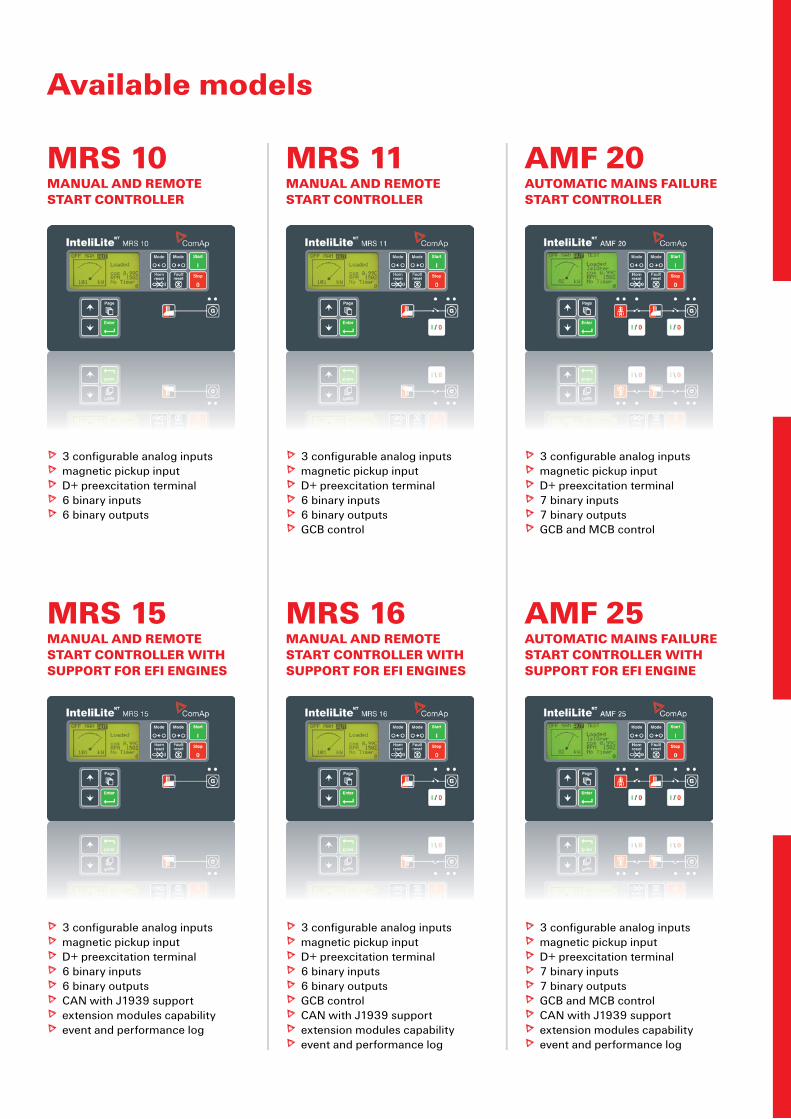
MRS 10MANUAL AND REMOTE START CONTROLLER
3 configurable analog inputs magnetic pickup input D+ preexcitation terminal 6 binary inputs6 binary outputs
Available models
MRS 16MANUAL AND REMOTE START CONTROLLER WITH SUPPORT FOR EFI ENGINES
3 configurable analog inputs magnetic pickup input D+ preexcitation terminal 6 binary inputs6 binary outputsGCB controlCAN with J1939 supportextension modules capabilityevent and performance log
AMF 20AUTOMATIC MAINS FAILURE START CONTROLLER
3 configurable analog inputs magnetic pickup input D+ preexcitation terminal 7 binary inputs7 binary outputsGCB and MCB control
AMF 25AUTOMATIC MAINS FAILURE START CONTROLLER WITH SUPPORT FOR EFI ENGINE
3 configurable analog inputs magnetic pickup input D+ preexcitation terminal 7 binary inputs7 binary outputsGCB and MCB controlCAN with J1939 supportextension modules capabilityevent and performance log
MRS 15MANUAL AND REMOTE START CONTROLLER WITH SUPPORT FOR EFI ENGINES
3 configurable analog inputs magnetic pickup input D+ preexcitation terminal 6 binary inputs6 binary outputsCAN with J1939 supportextension modules capabilityevent and performance log
MRS 11MANUAL AND REMOTE START CONTROLLER
3 configurable analog inputs magnetic pickup input D+ preexcitation terminal 6 binary inputs6 binary outputsGCB control

Features and specification are subject to change without prior notice 2007-09
ComAp, spol. s r. o.Czech RepublicPhone: + 420 246 012 111 Fax: + 420 266 316 647E-mail: [email protected]: www.comap.cz
MANUFACTURER: LOCAL DISTRIBUTOR / PARTNER:
www.comap.czFor more information about our products and solutions visit our web-page
FUNCTIONS/CONTROLLERS IL-NT MRS 10 IL-NT MRS 15 IL-NT MRS 11 IL-NT MRS 16 IL-NT AMF 20 IL-NT AMF 25
Binary inputs/outputs 6 / 6 6 / 6 6 / 6 6 / 6 7 / 7 7 / 7
Analog inputs 3 3 3 3 3 3
Magnetic pick-up l l l l l l
AMF function – – – – l l
Input configuration l l l l l l
Output configuration l l l l l l
Voltage measurement Gen. / Mains 3 ph / – 3 ph / – 3 ph / – 3 ph / – 3 ph / 3 ph 3 ph / 3 ph
Current measurement 3 ph3 ph,
IDMT overcurrent3 ph
3 ph, IDMT overcurrent
3 ph3 ph,
IDMT overcurrent
kW/kWh measurement l / – l / l l / – l / l l / – l / l
History file – l – l – l
RTC with battery l l l l l l
GCB/MCB control with feedback –1)/ – –1)/ – l2)/ – l2)/ – l / l l / l
Battery charging alternator circuit l l l l l l
J1939 interface – l – l – l
Internet support with IG-IB with IG-IB with IG-IB with IG-IB with IG-IB with IG-IB
Extension modules –IGL-RA15, IG-IOM,
IGS-PTM–
IGL-RA15, IG-IOM, IGS-PTM
–IGL-RA15, IG-IOM,
IGS-PTM
8 analog gauge drivers O O O O O O
RS232 interface O O O O O O
Modem interface O O O O O O
MODBUS interface O O O O O O
Remote display O O O O O O
Cummins MODBUS O O O O O O
Key: l included – excluded O optional – plug-in module required 1) Automatic GCB control without feedback 2) Manual/Automatic GCB control, but without feedback
Legend: IG-IOM/IGS-PTM: I/O extension modules IGL-RA15: Remote annunciator GCB: Generator circuit breaker MCB: Mains circuit breaker
The Chart of Functions of InteliLiteNT Controllers


![Conference Paper - PowerGen-Middle East 2008[1]](https://static.fdocuments.net/doc/165x107/577d35701a28ab3a6b906b92/conference-paper-powergen-middle-east-20081.jpg)

![Pojmovnik Eurovoc (verzija 4.1) - 24 financijemjesec.ffzg.hr/hidra-cd/pdf/p24.pdf · SP kretanje kapitala [PP 2421] SP devizni tečaj [PP 2411] SP međunarodno ekonomsko pravo [PP](https://static.fdocuments.net/doc/165x107/5e18df6151576317143ccb87/pojmovnik-eurovoc-verzija-41-24-sp-kretanje-kapitala-pp-2421-sp-devizni-teaj.jpg)


