MODEL H9291 12 BYRD SHELIX CUTTERHEAD - Grizzly
12
COPYRIGHT © NOVEMBER, 2008 BY GRIZZLY INDUSTRIAL, INC. WARNING: NO PORTION OF THIS MANUAL MAY BE REPRODUCED IN ANY SHAPE OR FORM WITHOUT THE WRITTEN APPROVAL OF GRIZZLY INDUSTRIAL, INC. #BL11319 The Model H9291 12" Byrd Shelix cutterhead is designed to replace the straight-knife cutterhead on the Grizzly jointer Model G0609. The total procedure of changing the cutterhead and setting up the jointer takes several hours. The job consists of removing the old cutterhead, installing the new helical cutterhead, and readjust- ing the outfeed table even with the carbide inserts at TDC (top dead center). Call Technical Support at (570) 546-9663 if you need help. Note: Some of the installation photos in these instructions may not show this specific Byrd Shelix cutterhead, but the concept is the same. Recommended Tools Qty Hex Wrench 3, 4, 8mm ................................ 1 Ea Wrench/Socket 10, 14, 19mm....................... 1 Ea Phillip Head Screwdriver ................................... 1 Lifting Assistants ............................................... 2 Standard Screwdriver ........................................ 1 Precision Straightedge (Figure 1 ) ..................... 1 Feeler Gauge Set .............................................. 1 Pair of Heavy Leather Gloves ........................... 1 Safety Glasses (per person).............................. 1 Pulley Puller ....................................................... 1 Arbor Press 18" Working Height........................ 1 Metal Rod 3 ⁄4" Diameter ..................................... 1 Metal Plates 4" x 9 x 1 ⁄ 2" .................................... 2 Hammer ............................................................. 1 Wood Blocks 24" 4x4......................................... 2 Wood Blocks 12" 2x4 ........................................ 2 Flat Piece of Scrap Wood ................................. 1 Degreaser .......................................... As Needed Shop Rag .......................................................... 1 MODEL H9291 12" BYRD ® SHELIX CUTTERHEAD INSTRUCTIONS Inventory (Figure 2) Qty A. Cutterhead with 96 Inserts ......................... 1 B. Socket Driver Bit Torx T25 1 ⁄4" Drive .......... 1 C. Socket Driver 1 ⁄4" Drive ............................... 1 D. Indexable Carbide Inserts 15 x 15 x 2.5 .... 5 Figure 2. Cutterhead inventory. C D B A Figure 1. Precision straightedges. G9644—12" Precision Straightedge H2675—16" Precision Straightedge Is your straightedge really straight? These grade 00 heavy-duty stainless steel straightedges are manufactured to DIN874 standards for profes- sional results in setup and inspection work.
Transcript of MODEL H9291 12 BYRD SHELIX CUTTERHEAD - Grizzly
COPYRIGHT © NOVEMBER, 2008 BY GRIZZLY INDUSTRIAL, INC. WARNING: NO PORTION OF THIS MANUAL MAY BE REPRODUCED IN ANY SHAPE
OR FORM WITHOUT THE WRITTEN APPROVAL OF GRIZZLY INDUSTRIAL, INC. #BL11319
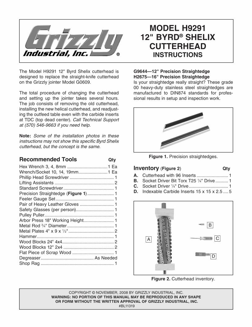
The Model H9291 12" Byrd Shelix cutterhead is designed to replace the straight-knife cutterhead on the Grizzly jointer Model G0609.
The total procedure of changing the cutterhead and setting up the jointer takes several hours. The job consists of removing the old cutterhead, installing the new helical cutterhead, and readjust-ing the outfeed table even with the carbide inserts at TDC (top dead center). Call Technical Support at (570) 546-9663 if you need help.
Note: Some of the installation photos in these instructions may not show this specific Byrd Shelix cutterhead, but the concept is the same.
Recommended Tools Qty
Hex Wrench 3, 4, 8mm ................................1 EaWrench/Socket 10, 14, 19mm .......................1 EaPhillip Head Screwdriver ................................... 1Lifting Assistants ............................................... 2Standard Screwdriver ........................................ 1Precision Straightedge (Figure 1) ..................... 1Feeler Gauge Set .............................................. 1Pair of Heavy Leather Gloves ........................... 1Safety Glasses (per person) .............................. 1Pulley Puller ....................................................... 1Arbor Press 18" Working Height ........................ 1Metal Rod 3⁄4" Diameter ..................................... 1Metal Plates 4" x 9 x 1⁄2" .................................... 2Hammer ............................................................. 1Wood Blocks 24" 4x4 ......................................... 2 Wood Blocks 12" 2x4 ........................................ 2Flat Piece of Scrap Wood ................................. 1 Degreaser .......................................... As NeededShop Rag .......................................................... 1
MODEL H929112" BYRD® SHELIX
CUTTERHEADINSTRUCTIONS
Inventory (Figure 2) Qty
A. Cutterhead with 96 Inserts ......................... 1B. Socket Driver Bit Torx T25 1⁄4" Drive .......... 1C. Socket Driver 1⁄4" Drive ............................... 1D. Indexable Carbide Inserts 15 x 15 x 2.5 .... 5
Figure 2. Cutterhead inventory.
C
D
B
A
Figure 1. Precision straightedges.
G9644—12" Precision StraightedgeH2675—16" Precision StraightedgeIs your straightedge really straight? These grade 00 heavy-duty stainless steel straightedges are manufactured to DIN874 standards for profes-sional results in setup and inspection work.

-2- H9291 12" Byrd® Shelix Cutterhead
Removing G0609 Cutterhead1. DISCONNECT JOINTER FROM POWER!
2. Remove the cutterhead guard and rabbet extension table.
3. Remove the lock nut securing the fence car-riage, then remove the fence assembly.
4. Remove the fence bracket, then remove both side access panels.
5. Open the motor access cover, loosen the fasteners on the tension rod, lift the motor up, then remove the V-belts.
6. Put on heavy leather gloves, then remove the knives.
—If you have difficulty accessing the knives, loosen the infeed and outfeed table locks, loosen the jam nuts and positive stop bolts located at the back of the machine, then lower the beds farther, as shown in Figure 3.
Figure 3. Jointer disassembly Steps 1–6.
8. Remove the hex nuts and flat washers that secure the handwheels, then remove both handwheels.
9. On the outfeed side of the jointer, remove the three Phillips head screws that secure the bearing support plate to the cabinet (Figure 4).
Figure 4. Bearing support plate screws.
10. Loosen the set screw that secures the collar on the spiral gear shaft behind the P-housing (Figure 5).
Figure 5. Collar on spiral gear shaft.
Collar
Jointer knives are extremely sharp. You must remove the jointer knives to avoid the risk of serious personal injury during the following steps.
7. Raise both beds all the way up, then tighten the infeed and outfeed table locks. This bed position will make future steps easier while replacing the cutterhead.
P-Housing
Set Screw
Spiral Gear Shaft
Location Where Handwheel Was
Removed

H9291 12" Byrd® Shelix Cutterhead -3-
11. Slide out the spiral gear shaft assembly (Figure 6) through the front of the cabinet.
Figure 6. Removing spiral gear shaft.
12. Repeat Steps 9-11 on the right side of the jointer.
13. Remove the M8-1.25 x 25 cap screws and lock washers securing the stand to the base.
14. During the following steps, you will lift the base off of the cabinet to access the cutterhead, so it can be removed. This can be accomplished using power lifting equipment or by using boards.
—If you have a forklift, engine hoist or boom crane, wrap lifting straps with a 900 lb. capacity around the infeed and outfeed tables. Position the straps as close to the base as possible to prevent damaging the tables. With the lifting straps positioned evenly, lift the jointer off of the cabi-net approximately four inches. Proceed to Step 15.
Figure 8. Jointer bed supported with 4x4s on both ends.
Figure 7. 4x4 placed between cabinet and bed on infeed side of jointer.
Note: Be careful not to knock off the rubber gaskets (Figure 7) located on the bottom of the base. If you accidentally knock the gas-kets loose, place them in a safe location for later reinstallation.
16. Repeat Step 15 on the other side to support the outfeed table (Figure 8).
15. While two assistants lift the infeed table, place a 24" long 4x4 board (or two 2x4s nailed together) between the cabinet and bed, as shown in Figure 7.
Rubber Gasket
4x4

-4- H9291 12" Byrd® Shelix Cutterhead
17. Reach inside the base and remove the hex bolts and lock washers that secure the cutterhead to the base (see Figure 9).
Flat Washer
Hex Bolt
Jointer Base
Cutterhead
Figure 9. Removing cutterhead fasteners.
18. Mark the side of the front bearing block that faces the front of the machine (Figure 10) with tape or a felt marker, to make it easier to reinstall the bearing blocks later.
Figure 10. Location to mark front bearing block.
Mark Here
19. Carefully slide the cutterhead assembly out the back of the jointer (see Figure 11).
Figure 11. Cutterhead removed.
20. Place the cutterhead on a workbench.
21. Remove the left-hand thread hex bolt and flat washer that secure the pulley, use a pulley puller to remove the pulley from the cutterhead (Figure 12), then remove the key.
Figure 12. Removing pulley.

H9291 12" Byrd® Shelix Cutterhead -5-
Wear a face shield during the next step! The metal rod could spring out and hit you as you press the cutterhead out.
23. Have an assistant hold the cutterhead so it does not suddenly drop, then press the cutterhead shaft off of the rear bearing block.
24. Remove the three cap screws that secure the front bearing block cap, then remove the cap with a standard screwdriver.
25. Remove the hex bolt and flat washer that secure the bearing on the cutterhead.
26. Repeat Steps 22–23 in a similar manner to remove the cutterhead from the front bear-ing block and bearing. Figure 14 shows the disassembled components.
22. Place the cutterhead in an arbor press. Insert a metal rod between the press and the cutterhead shaft, and place metal plates between the cutterhead and rear bearing block, as shown in Figure 13, to support it.
Figure 13. Preparing to remove rear bearing block.
Cutterhead
Metal Rod
Metal Plates
Rear Bearing Block
Figure 14. Disassembled cutterhead assembly.
Figure 15. Reinstalling rear bearing block assembly.
2. Slide the rear bearing block as far as possible onto the longer length of the cutterhead shaft, as shown in Figure 15.
Jointer carbide inserts are extremely sharp. Wear leather gloves to avoid the risk of serious personal injury during the following steps.
Installing H9291 Cutterhead1. Remove the protective waxy oil coating from
the H9291 cutterhead—if there is any, with a solvent cleaner or degreaser, such as the one shown in Accessories on Page 9. Avoid chorine-based solvents, such as acetone or brake parts cleaner that may damage painted surfaces. Always follow the manufacturer's instructions when using any type of cleaning product.
Rear Bearing Block
Rear Bearing Block
Front Bearing Block
Front Bearing Block Cap
-6- H9291 12" Byrd® Shelix Cutterhead
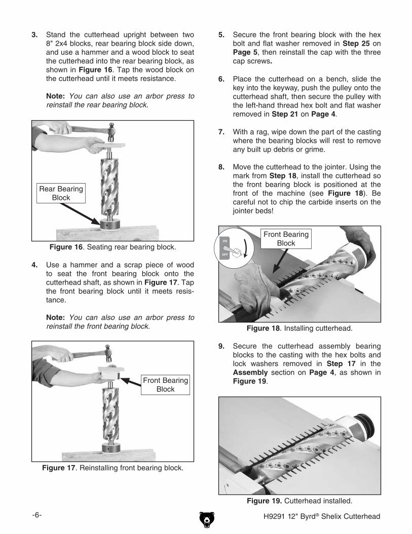
3. Stand the cutterhead upright between two 8" 2x4 blocks, rear bearing block side down, and use a hammer and a wood block to seat the cutterhead into the rear bearing block, as shown in Figure 16. Tap the wood block on the cutterhead until it meets resistance.
Note: You can also use an arbor press to reinstall the rear bearing block.
Figure 16. Seating rear bearing block.
5. Secure the front bearing block with the hex bolt and flat washer removed in Step 25 on Page 5, then reinstall the cap with the three cap screws.
9. Secure the cutterhead assembly bearing blocks to the casting with the hex bolts and lock washers removed in Step 17 in the Assembly section on Page 4, as shown in Figure 19.
6. Place the cutterhead on a bench, slide the key into the keyway, push the pulley onto the cutterhead shaft, then secure the pulley with the left-hand thread hex bolt and flat washer removed in Step 21 on Page 4.
7. With a rag, wipe down the part of the casting where the bearing blocks will rest to remove any built up debris or grime.
8. Move the cutterhead to the jointer. Using the mark from Step 18, install the cutterhead so the front bearing block is positioned at the front of the machine (see Figure 18). Be careful not to chip the carbide inserts on the jointer beds!
Figure 18. Installing cutterhead.
Front Bearing Block
Figure 19. Cutterhead installed.
Rear Bearing Block
4. Use a hammer and a scrap piece of wood to seat the front bearing block onto the cutterhead shaft, as shown in Figure 17. Tap the front bearing block until it meets resis-tance.
Note: You can also use an arbor press to reinstall the front bearing block.
Figure 17. Reinstalling front bearing block.
Front Bearing Block

H9291 12" Byrd® Shelix Cutterhead -7-
Figure 20. Checking cutterhead parallelism.
Straightedge
Outfeed Table
10. Reinstall any gaskets that were knocked off earlier onto the bottom of the base.
11. Place the base back onto the cabinet, using power lifting equipment or with two lifting assistants.
—If you used power lifting equipment to raise the bed off of the cabinet to remove the Model G0609 cutterhead, make sure the 900 lb. capacity straps are wrapped correctly around the infeed and outfeed tables, remove the 4x4 boards, then lower the bed onto the cabinet.
—If you did not use power lifting equipment but only placed boards between the base and cabinet, have two lifting assistants carefully lower each side of the base onto the cabinet while you remove the 4x4 boards between the cabinet and beds.
12. Repeat Steps 8–12 in the Assembly section on Pages 2–3 in reverse order—to reinstall the spiral gear shafts and handwheel assem-blies.
13. Raise the outfeed table up as far as pos-sible.
14. Using the straightedge and feeler gauge set, inspect the cutterhead parallelism with the outfeed table as shown in Figure 20. With the straightedge in position, raise or lower the outfeed table until the cutterhead body (not the carbide insert) just touches the straight-edge.
15. Move the straightedge to the other side to determine if one end of the cutterhead body is higher/lower than the other. (Place the feeler gauge between the cutterhead body and the straightedge to determine the height difference.)
—If the cutterhead body is even with or within 0.004" of the outfeed table from one side to the other, skip to Step 16.
—If the cutterhead is over 0.004" from one side to the other, follow the instructions in your G0609 manual on Pages 38-39 for checking infeed table parallelism and adjusting table parallelism. Once the tables are parallel to the cutterhead, proceed to Step 16.
16. Secure the base to the stand with the M8-1.25 x 25 cap screws and lock washers removed earlier.
17. Reinstall the V-belts on the pulleys. (Refer to the instructions in your jointer manual for details.)
18. Place a straightedge on the outfeed table so it extends over the cutterhead, and rotate the cutterhead pulley until one of the carbide inserts is at top-dead-center (TDC), as shown in Figures 21 & 22.
Figure 21. Cutterhead insert at top-dead-center.
Top DeadCenter
Bottom DeadCenter

-8- H9291 12" Byrd® Shelix Cutterhead
19. Lock the outfeed table lock, then reinstall the fence bracket and the fence assembly, then secure the fence carriage with the lock nut.
20. Reinstall the rabbet extension table.
21. Reinstall the cutterhead guard back over the cutterhead, making sure that the spring ten-sion in the guard is properly set so the guard springs back over the cutterhead when it is pulled back and released.
22. Re-adjust the infeed table.
23. Reset the positive stop bolts on the infeed and outfeed tables.
24. Reinstall the motor cover and side access panels.
Figure 24. Rotating indexable carbide inserts.
BT
BT
BT
BT
Insert ServiceThe Model H9291 12" cutterhead is equipped with 96 indexable carbide inserts. Each insert can be rotated to reveal any one of its four cutting edges. Therefore, if one cutting edge becomes dull or damaged, simply rotate it clockwise 90˚ to reveal a fresh cutting edge (Figure 24).
Reference Letters
When correctly set, the carbide insert will just touch the straightedge at its highest point of rota-tion and move it slightly 1⁄8" forward or backward when you rotate the cutterhead pulley (see Figure 23).
Figure 22. Example of setting outfeed table height.
Figure 23. Using a straightedge to align outfeed table height with insert at TDC.
Straightedge
Outfeed Infeed
—If your outfeed table is correctly set, no adjustments are necessary.
—If the insert lifts the straightedge off the table and moves it more than 1⁄8" when you rotate the cutterhead pulley, or the table is below the straightedge, adjust the outfeed table height with the outfeed table handwheel until the straightedge just touches an insert at its highest point of rotation.
In addition, each insert has reference letters on one corner. As the insert is rotated, the reference letters location can be used as an indicator of which edges are used and which are new. The insert must be replaced when all four edges are dull.

H9291 12" Byrd® Shelix Cutterhead -9-
AccessoriesG8995—4" Heavy Duty Pulley PullerIndispensable for pulling gears or pulley off of press-fit shafts. Can be used in either a 2 or 3 jaw configuration. The 4" jaw fingers are also revers-ible so they can grab an outside or inside diam-eter. The forcing screw has a live center and is made of tough hardened steel. Keep one of these handy in your tool box.
H7354—10 Pack Shelix Carbide InsertsReplacement inserts for H9291 cutterhead.
Figure 26. G8995 4" Heavy Duty Pulley Puller.
Figure 27. H7354 Indexable Carbide Inserts.
To Install or adjust a carbide cutter:
1. DISCONNECT JOINTER FROM POWER!
2. Remove any sawdust from the head of the carbide insert Torx screw.
3. Remove the Torx screw and carbide insert.
4. Clean all dust and dirt off the insert and the cutterhead seat from which the insert was removed.
Note: Proper cleaning is critical to achieving a smooth finish. Dirt or dust trapped between the insert and seat will slightly raise the insert, and make noticeable marks on your workpieces the next time you cut.
5. Replace the insert so a fresh, sharp edge is facing outward, and the insert is slightly for-ward of the seat back— so a gap is created and the cutter hole is offset from the seat hole, as shown in Figure 25.
— If you place the insert directly over the seat hole or against the seat back the insert may not be drawn flush with the seat dur-ing the next step, increasing the risk of the cutter cracking.
6. Lubricate the Torx screw threads with a light machine oil, wipe the excess oil off the threads, and torque the Torx screw to 55 inch/pounds (hand tight).
Note: Excess oil may squeeze between the insert and seat or in the screw hole, thereby lifting the insert or screw slightly and affecting workpiece finishes.
Figure 25. Carbide insert positioned slightly forward on seat.
Gap
SeatBack
G2544—Solvent Cleaner & DegreaserH9692—Orange Power DegreaserGreat products for removing shipping grease.
Figure 28. Cleaner/degreasers available from Grizzly.

-10- H9291 12" Byrd® Shelix Cutterhead
H9291 Parts Breakdown and List
1
4
3
5
2
REF PART # DESCRIPTION1 PH9291001 SHELIX CUTTERHEAD 12"2 PH9291002 SOCKET DRIVER BIT TORX T25 1/4" DRIVE3 PH9291003 SOCKET DRIVER 1/4" DRIVE4 PH9291004 INDEXABLE INSERT 15 X 15 X 2.55 PFH68M FLAT HD TORX SCR T25 M5-.8 X 12