MODEL G0509 & G0509G 16 x 40 LATHE - Grizzlycdn0.grizzly.com/manuals/g0509g_m.pdf · Main...
92
COPYRIGHT © MAY, 2007 BY GRIZZLY INDUSTRIAL, INC. REVISED MARCH, 2016 (TR) WARNING: NO PORTION OF THIS MANUAL MAY BE REPRODUCED IN ANY SHAPE OR FORM WITHOUT THE WRITTEN APPROVAL OF GRIZZLY INDUSTRIAL, INC. #CR9246 PRINTED IN CHINA MODEL G0509 & G0509G 16" x 40" LATHE OWNER'S MANUAL MODEL G0509G PROFESSIONAL GUNSMITH'S LATHE SHOWN
Transcript of MODEL G0509 & G0509G 16 x 40 LATHE - Grizzlycdn0.grizzly.com/manuals/g0509g_m.pdf · Main...

COPYRIGHT © MAY, 2007 BY GRIZZLY INDUSTRIAL, INC. REVISED MARCH, 2016 (TR)WARNING: NO PORTION OF THIS MANUAL MAY BE REPRODUCED IN ANY SHAPE
OR FORM WITHOUT THE WRITTEN APPROVAL OF GRIZZLY INDUSTRIAL, INC. #CR9246 PRINTED IN CHINA
MODEL G0509 & G0509G 16" x 40" LATHE
OWNER'S MANUAL
MODEL G0509G PROFESSIONAL GUNSMITH'S LATHE SHOWN

This manual provides critical safety instructions on the proper setup, operation, maintenance, and service of this machine/tool. Save this document, refer to it often, and use it to instruct other operators.
Failure to read, understand and follow the instructions in this manual may result in fire or serious personal injury—including amputation, electrocution, or death.
The owner of this machine/tool is solely responsible for its safe use. This responsibility includes but is not limited to proper installation in a safe environment, personnel training and usage authorization, proper inspection and maintenance, manual availability and compre-hension, application of safety devices, cutting/sanding/grinding tool integrity, and the usage of personal protective equipment.
The manufacturer will not be held liable for injury or property damage from negligence, improper training, machine modifications or misuse.
Some dust created by power sanding, sawing, grinding, drilling, and other construction activities contains chemicals known to the State of California to cause cancer, birth defects or other reproductive harm. Some examples of these chemicals are:
• Lead from lead-based paints.• Crystalline silica from bricks, cement and other masonry products.• Arsenic and chromium from chemically-treated lumber.
Your risk from these exposures varies, depending on how often you do this type of work. To reduce your exposure to these chemicals: Work in a well ventilated area, and work with approved safety equip-ment, such as those dust masks that are specially designed to filter out microscopic particles.

G0509 & G0509G 16" x 40" Lathe -1-
INTRODUCTION ............................................... 2Foreword ........................................................ 2Contact Info.................................................... 2Data Sheet Model G0509 .............................. 3Data Sheet Model G0509G ........................... 6Identification ................................................... 9
SECTION 1: SAFETY ..................................... 10Additional Safety Instructions for Lathes ..... 12Glossary of Terms ....................................... 13
SECTION 2: CIRCUIT REQUIREMENTS ...... 14220V 3-Phase .............................................. 14Operation ..................................................... 14Phase Converter .......................................... 14
SECTION 3: SETUP ....................................... 15Setup Safety ................................................ 15Items Needed for Setup ............................... 15Unpacking .................................................... 15Inventory ...................................................... 16Site Considerations ...................................... 17Clean Up ...................................................... 17Lifting & Moving the Lathe ........................... 18Mounting to Shop Floor ............................... 19Test Run & Break-In ................................... 20Changing Motor Rotation ............................. 22Tailstock Setup ............................................ 23Gap Removal ............................................... 24
SECTION 4: OPERATION .............................. 25Operation Safety .......................................... 25Spindle Speeds ............................................ 26Gearbox Speed Range lever ....................... 27Feed Rod and Leadscrew............................ 28Gearbox Ratio Levers .................................. 28Manual Feed Handwheels ........................... 30Power Feed Direction Knob ......................... 30Tool Post & Holder....................................... 30Half-Nut Lever and Thread Dial ................... 31Steady Rest ................................................. 32Follow Rest .................................................. 32Tailstock Controls ........................................ 33Centers ........................................................ 33Spider (G0509G).......................................... 34Manual Micrometer Stop .............................. 34Chuck & Faceplate ...................................... 35Mounting ..................................................... 35Camlock Stud Adjustment ........................... 37
SECTION 5: ACCESSORIES ......................... 38
SECTION 6: MAINTENANCE ......................... 40Basic Maintenance....................................... 40Lubrication ................................................... 40Coolant System............................................ 42
SECTION 7: SERVICE ................................... 43Troubleshooting ........................................... 43Gibs .............................................................. 45Cross Slide Leadscrew Adjustment ............. 46Leadscrew Endplay Adjustment .................. 47Halfnut Adjustment....................................... 47V-Belts ......................................................... 48Brake & Switch ............................................ 48Bearing Preload ........................................... 49Spindle Balancing ....................................... 51Main Electrical Box ..................................... 52Motors & Switches ...................................... 53Control Panel & Switches ........................... 54Component Relationship Diagram .............. 55Main Electrical Box Wiring Diagram ........... 56Component Wiring Diagram ....................... 57
SECTION 8: PARTS ....................................... 58Accessories .................................................. 58Parts List ...................................................... 59Frame, Ways, & Stand (1-2) ........................ 60Frame, Ways, & Stand (2-2) ........................ 61Parts List ...................................................... 62Headstock (1-3) ........................................... 63Headstock (2-3) ........................................... 64Headstock (3-3) ........................................... 65Parts List ...................................................... 66Gearbox (1-3)............................................... 68Gearbox (2-3)............................................... 69Gearbox (3-3)............................................... 70Parts List ...................................................... 71Apron (1-2) ................................................... 73Apron (2-2) ................................................... 74Parts List ...................................................... 75Cross Slide, Compound Rest, Oil Pump ..... 76Oil Pump ...................................................... 77Parts List ...................................................... 78Tailstock ....................................................... 80Parts List ...................................................... 81Steady Rest & Follow Rest .......................... 82Parts List ...................................................... 82Electrical & Coolant System ........................ 83Parts List ...................................................... 84Labels & Placement ..................................... 85Parts List ...................................................... 85
WARRANTY AND RETURNS ........................ 86
Table of Contents

-2- G0509 & G0509G 16" x 40" Lathe
If you have any comments regarding this manual, please write to us at the address below:
Grizzly Industrial, Inc.C/O Technical Documentation Manager
P.O. Box 2069Bellingham, WA 98227-2069Email: [email protected]
We stand behind our machines. If you have any service questions or parts requests, please call or write us at the location listed below.
Grizzly Industrial, Inc.1203 Lycoming Mall Circle
Muncy, PA 17756Phone: (570) 546-9663
Fax: (800) 438-5901E-Mail: [email protected] Site: http://www.grizzly.com
Foreword
INTRODUCTION
Contact Info
We are proud to offer the Model G0509/G0509G 16" x 40" Lathe. This machine is part of a grow-ing Grizzly family of fine metalworking machinery. When used according to the guidelines set forth in this manual, you can expect years of trouble-free, enjoyable operation and proof of Grizzly’s com-mitment to customer satisfaction.
We are pleased to provide this manual with the Model G0509/G0509G. It was written to guide you through assembly, review safety consider-ations, and cover general operating procedures. It represents our effort to produce the best docu-mentation possible.
The specifications, drawings, and photographs illustrated in this manual represent the Model G0509/G0509G 16" x 40" Lathe as supplied when the manual was prepared. However, owing to Grizzly’s policy of continuous improvement, changes may be made at any time with no obliga-tion on the part of Grizzly. For your convenience, we always keep current Grizzly manuals available on our website at www.grizzly.com. Any updates to your machine will be reflected in these manuals as soon as they are complete. Visit our site often to check for the latest updates to this manual!

G0509 & G0509G 16" x 40" Lathe -3-
The information contained herein is deemed accurate as of 6/1/2017 and represents our most recent product specifications.Due to our ongoing improvement efforts, this information may not accurately describe items previously purchased. PAGE 1 OF 3Model G0509
MACHINE DATASHEET
Customer Service #: (570) 546-9663 · To Order Call: (800) 523-4777 · Fax #: (800) 438-5901
MODEL G0509 16" X 40" LATHEProduct Dimensions:
Weight............................................................................................................................................................ 3100 lbs.Width (side-to-side) x Depth (front-to-back) x Height.................................................... 76-3/8 x 33-7/16 x 51-3/16 in.Footprint (Length x Width)..................................................................................................................... 76 x 21-1/2 in.
Shipping Dimensions:
Type.......................................................................................................................................................... Wood CrateContent........................................................................................................................................................... MachineWeight............................................................................................................................................................ 3245 lbs.Length x Width x Height....................................................................................................................... 64 x 81 x 36 in.
Electrical:
Power Requirement................................................................................................................... 220V, 3-Phase, 60 HzPrewired Voltage.................................................................................................................................................. 220VFull-Load Current Rating................................................................................................................................... 15.45AMinimum Circuit Size.............................................................................................................................................. 20AConnection Type....................................................................................................................................... Cord & PlugPower Cord Included.............................................................................................................................................. YesPower Cord Length................................................................................................................................................. 6 ft.Power Cord Gauge......................................................................................................................................... 12 AWGPlug Included........................................................................................................................................................... NoSwitch Type..................................................................................... Magnetic Switch w/Thermal Overload ProtectionRecommended Phase Converter....................................................................................................................... G7978
Motors:
Main
Type........................................................................................................................................... TEFC InductionHorsepower..................................................................................................................................... 4 HP / 3 HPPhase.................................................................................................................................................... 3-PhaseAmps..................................................................................................................................................... 15A/10ASpeed..................................................................................................................................... 3450 / 1725 RPMPower Transfer .................................................................................................................................. Belt DriveBearings..................................................................................................... Shielded & Permanently Lubricated
Coolant Pump
Type........................................................................................................................................... TEFC InductionHorsepower............................................................................................................................................. 1/8 HPPhase.................................................................................................................................................... 3-PhaseAmps......................................................................................................................................................... 0.45ASpeed................................................................................................................................................ 3450 RPMPower Transfer ............................................................................................................................... Direct DriveBearings..................................................................................................... Shielded & Permanently Lubricated
Data Sheet Model G0509

-4- G0509 & G0509G 16" x 40" Lathe
The information contained herein is deemed accurate as of 6/1/2017 and represents our most recent product specifications.Due to our ongoing improvement efforts, this information may not accurately describe items previously purchased. PAGE 2 OF 3Model G0509
Main Specifications:
Operation Info
Swing Over Bed......................................................................................................................................... 16 in.Distance Between Centers........................................................................................................................ 40 in.Swing Over Cross Slide............................................................................................................................. 10 in.Swing Over Saddle................................................................................................................................ 9-7/8 in.Swing Over Gap........................................................................................................................................ 22 in.Maximum Tool Bit Size............................................................................................................................. 3/4 in.Compound Travel.................................................................................................................................. 5-1/2 in.Carriage Travel.......................................................................................................................................... 33 in.Cross Slide Travel................................................................................................................................. 8-1/2 in.
Headstock Info
Spindle Bore....................................................................................................................................... 2.0625 in.Spindle Taper............................................................................................................................................ MT#6Number of Spindle Speeds............................................................................................................................. 16Spindle Speeds......................................................................................................................... 45 – 1800 RPMSpindle Type................................................................................................................................ D1-6 CamlockSpindle Bearings......................................................................................................................... Tapered RollerSpindle Length........................................................................................................................................... 20 in.Spindle Length with 3-Jaw Chuck.............................................................................................................. 25 in.Spindle Length with 4-Jaw Chuck....................................................................................................... 25-1/8 in.
Tailstock Info
Tailstock Quill Travel............................................................................................................................. 4-3/4 in.Tailstock Taper.......................................................................................................................................... MT#4Tailstock Barrel Diameter............................................................................................................................ 2 in.
Threading Info
Number of Longitudinal Feeds....................................................................................................................... 17Range of Longitudinal Feeds............................................................................................ 0.002 – 0.067 in./rev.Number of Cross Feeds................................................................................................................................. 17Range of Cross Feeds................................................................................................... 0.0011 – 0.0380 in./revNumber of Inch Threads................................................................................................................................. 45Range of Inch Threads...................................................................................................................... 2 – 72 TPINumber of Metric Threads.............................................................................................................................. 39Range of Metric Threads............................................................................................................. 0.2 – 14.0 mmNumber of Modular Pitches............................................................................................................................ 18Range of Modular Pitches.............................................................................................................. 0.3 – 3.5 MPNumber of Diametral Pitches.......................................................................................................................... 21Range of Diametral Pitches................................................................................................................ 8 – 44 DP
Dimensions
Bed Width.................................................................................................................................................. 10 in.Carriage Leadscrew Diameter.............................................................................................................. 1.120 in.Leadscrew TPI........................................................................................................................................... 4 TPICarriage Leadscrew Length....................................................................................................................... 54 in.Steady Rest Capacity............................................................................................................................ 4-7/8 in.Follow Rest Capacity............................................................................................................................. 2-7/8 in.Faceplate Size........................................................................................................................................... 14 in.Feed Rod Diameter.................................................................................................................................. 3/4 in.Floor to Center Height............................................................................................................................... 45 in.
Construction
Base..................................................................................................................................................... Cast IronHeadstock............................................................................................................................................ Cast IronEnd Gears...................................................................................................................... Flame Hardened SteelBed........................................................................................ Induction-Hardened, Precision-Ground Cast IronBody..................................................................................................................................................... Cast IronStand.................................................................................................................................................... Cast IronPaint Type/Finish...................................................................................................................................... Epoxy

G0509 & G0509G 16" x 40" Lathe -5-
The information contained herein is deemed accurate as of 6/1/2017 and represents our most recent product specifications.Due to our ongoing improvement efforts, this information may not accurately describe items previously purchased. PAGE 3 OF 3Model G0509
Other Specifications:
Country of Origin ................................................................................................................................................ ChinaWarranty ........................................................................................................................................................... 1 YearApproximate Assembly & Setup Time ............................................................................................................. 2 HoursSerial Number Location ............................................................................................. ID Label on Front of HeadstockISO 9001 Factory .................................................................................................................................................... NoCertified by a Nationally Recognized Testing Laboratory (NRTL) .......................................................................... No
Features:
Coolant SystemFoot BrakeFull Length Splash GuardHalogen LightHeadstock Gears Run in an Oil BathInch/Metric DialsJog Button and Emergency StopPrecision-Ground V-Bed is Made of Meehanite CastingThreading DialTotally Enclosed Universal Gearbox Allows Cutting of Inch, Metric, Whitworth, Module, and Diametral Threads
Accessories Included:
Center SleeveCentersFollow RestManualMT#4 Dead CenterQuick Change Tool Post Service ToolsSteady RestToolbox#4 to 6 Morse Taper Spindle Nose Sleeve12" 4-Jaw Chuck14" Face Plate8" 3-Jaw Chuck

-6- G0509 & G0509G 16" x 40" Lathe
The information contained herein is deemed accurate as of 5/24/2007 and represents our most recent product specifications.Due to our ongoing improvement efforts, this information may not accurately describe items previously purchased. PAGE 1 OF 3Model G0509G
MACHINE DATASHEET
Customer Service #: (570) 546-9663 · To Order Call: (800) 523-4777 · Fax #: (800) 438-5901
MODEL G0509G 16" X 40" 3-PHASE GUNSMITH METALLATHE
Product Dimensions:
Weight............................................................................................................................................................ 2976 lbs.Length/Width/Height.......................................................................................................76-3/8 x 33-7/16 x 51-3/16 in.Foot Print (Length/Width)....................................................................................................................... 76 x 21-1/2 in.
Shipping Dimensions:
Type........................................................................................................................................................... Wood CrateContent............................................................................................................................................................ MachineWeight............................................................................................................................................................ 3248 lbs.Length/Width/Height............................................................................................................................. 82 x 33 x 65 in.
Electrical:
Switch........................................................................................................................Jog Button and Emergency StopSwitch Voltage...................................................................................................................................................... 220VCord Length............................................................................................................................................................ 6 ft.Cord Gauge....................................................................................................................................................12 gaugeRecommended Breaker Size............................................................................................................................ 20 ampPlug.......................................................................................................................................................................... NoPhase Converter................................................................................................................................................ G7978
Motors:
Spindle
Type....................................................................................................................................... 2-Speed InductionHorsepower............................................................................................................................................3 - 4 HPVoltage........................................................................................................................................................220VPrewired......................................................................................................................................................220VPhase.........................................................................................................................................................ThreeAmps.......................................................................................................................................................17/8.5ASpeed..........................................................................................................................................1750/875 RPMCycle..........................................................................................................................................................60 HzNumber Of Speeds........................................................................................................................................... 2Power Transfer ...................................................................................................................... Belt Drive to GearBearings........................................................................................................... Shielded and Lubricated for Life
Coolant
Type......................................................................................................................................................InductionHorsepower..............................................................................................................................................1/8 HPVoltage........................................................................................................................................................220VPrewired......................................................................................................................................................220VPhase.........................................................................................................................................................ThreeAmps..........................................................................................................................................................0.45ASpeed.................................................................................................................................................3450 RPMCycle..........................................................................................................................................................60 HzNumber Of Speeds........................................................................................................................................... 1Power Transfer ................................................................................................................................Direct DriveBearings.................................................................................................. Shielded and Permanently Lubricated
Data Sheet Model G0509G

G0509 & G0509G 16" x 40" Lathe -7-
The information contained herein is deemed accurate as of 5/24/2007 and represents our most recent product specifications.Due to our ongoing improvement efforts, this information may not accurately describe items previously purchased. PAGE 2 OF 3Model G0509G
Main Specifications:
Operation Info
Swing Over Bed......................................................................................................................................... 16 in.Dist Between Centers.................................................................................................................................40 in.Swing Over Cross Slide............................................................................................................................. 10 in.Swing Over Saddle...............................................................................................................................14-3/4 in.Swing Over Gap......................................................................................................................................... 22 in.Max Tool Bit Size...................................................................................................................................... 3/4 in.Compound Travel...................................................................................................................................5-1/2 in.Carriage Travel...........................................................................................................................................33 in.Cross Slide Travel..................................................................................................................................8-1/2 in.
Headstock Info
Spindle Bore.................................................................................................................................................2 in.Spindle Size......................................................................................................................................... 3-9/64 in.Spindle Taper.............................................................................................................................................MT#6No Of Spindle Speeds.....................................................................................................................................16Range Of Spindle Speeds.......................................................................................................... 45 - 1800 RPMSpindle Type................................................................................................................................ D1-6 CamlockSpindle Bearings............................................................................................................... Super High Precision
Tailstock Info
Tailstock Travel...................................................................................................................................... 4-3/4 in.Tailstock Taper.......................................................................................................................................... MT#4Tailstock Barrel Diameter............................................................................................................................. 2 in.
Threading Info
No Of Inch Threads.........................................................................................................................................45Range Of Inch Threads....................................................................................................................... 2 - 72 TPIRange Of Longitudinal Feeds................................................................................................... 0.002 - 0.067 in.No Of Longitudinal Feeds............................................................................................................................... 17No Of Cross Feeds......................................................................................................................................... 17Range Of Cross Feeds.................................................................................................... 0.0011 - 0.038 in./rev.No Of Metric Threads......................................................................................................................................39Range Of Metric Threads.................................................................................................................0.2 - 14 mmNo Of Modular Threads...................................................................................................................................18Range Of Modular Threads............................................................................................................. 0.3 - 3.5 MPNo Of Diametrical Threads..............................................................................................................................21Range Of Diametrical Threads............................................................................................................ 8 - 44 DP
Dimensions
Bed Width...................................................................................................................................................10 in.Leadscrew TPI.................................................................................................................................................. 4Leadscrew Length...................................................................................................................................... 54 in.Steady Rest Capacity.................................................................................................................... 1/2 - 4-1/2 in.Follow Rest Capacity..................................................................................................................... 1/2 - 2-1/2 in.Faceplate Size............................................................................................................................................14 in.Leadscrew Diameter............................................................................................................................. 1.120 in.Feed Rod Diameter............................................................................................................................... 0.745 in.Floor To Center Height...............................................................................................................................47 in.
Construction
Base Construction................................................................................................................................ Cast IronHeadstock Construction....................................................................................................................... Cast IronHeadstock Gears Construction....................................................................................... Flame Hardened SteelBed Construction..................................................................................................Induction Hardened Cast IronBody Construction................................................................................................................................ Cast IronStand Construction............................................................................................................................... Cast IronPaint.......................................................................................................................................................... Epoxy

-8- G0509 & G0509G 16" x 40" Lathe
The information contained herein is deemed accurate as of 5/24/2007 and represents our most recent product specifications.Due to our ongoing improvement efforts, this information may not accurately describe items previously purchased. PAGE 3 OF 3Model G0509G
Other
Kilowatt Output...........................................................................................................................................3.077
Other Specifications:
Country Of Origin ................................................................................................................................................ChinaWarranty ............................................................................................................................................................ 1 YearSerial Number Location ................................................................................................................. Front of HeadstockAssembly Time .................................................................................................................................................2 hours
Features:
Precision Gound and Hardened V-bed is Made of Meehanite CastingTotally Enclosed Universal Gearbox Allows Cutting of Inch, Metric, Whitworth, Modular and Diametral ThreadsHeadstock Gears Runs in an Oil Bath and are Hardened and Precision Ground for Smooth, Quiet and VibrationDual Inch/Metric DialsHalogen LightCoolant SystemFull Length Splash GuardSteady Rest and Follow Rest have Roller TipsDual Coolant Nozzles for Chambering BarrelsExtra Long Tailstock for SupportTailstock can be Tightened with a Torque Wrench for Precise Alignment of CentersFour Brass Tipper Bolts for Supporting Gun Barrels
Accessories Included:
#4 to 6 Morse Taper Spindle Nose Sleeve12" 4-Jaw Chuck14" Face Plate8" 3-Jaw ChuckCenter SleeveCentersFollow Rest with Roller TipsMT#4 Dead CenterQuick Change Tool PostService ToolsSteady Rest with Roller TipsToolbox

G0509 & G0509G 16" x 40" Lathe -9-
Identification
Figure 1. Model G0509G identification.
A. Headstock Low/High Range LeverB. Headstock Speed LeverC. Emergency Stop/RESET ButtonD. Inching/Jog ButtonE. 3-Jaw ChuckF. Steady RestG. Quick Change Tool Holder and PostH. Follow RestI. Coolant Nozzle AJ. Halogen Work LampK. Compound Rest Handwheel & Inch/Metric SleeveL. Coolant Nozzle BM. Tailstock Barrel Lock LeverN. Tailstock Lock LeverO. Tailstock HandwheelP. Apron Hand PumpQ. Coolant Pump and Tank Access Panel
R. Spindle Rotation ON/OFF LeverS. Threading Dial AssemblyT. Halfnut LeverU. Apron Feed Direction KnobV. Feed Selector LeverW. Cross Slide Handwheel & Inch/Metric SleeveX. Foot BrakeY. Apron HandwheelZ. Manual Micrometer StopAA. Motor High/Low Range SwitchBB. Gearbox Ratio LeversCC. Gearbox speed range leverDD. Pump ON/OFF SwitchEE. Power ON LampFF. Gearbox High/Low Range LeverGG. Leadscrew/Feed Rod Direction Lever
AB C
D
EF G
H I J
K L MN
O
P
Q
R
ST
UV
W
ZY
X
AA
BB
CC
BB
BB
DD
EE
FF
GG
-10- G0509 & G0509G 16" x 40" Lathe
ELECTRICAL EQUIPMENT INJURY RISKS. You can be shocked, burned, or killed by touching live electrical components or improperly grounded machinery. To reduce this risk, only allow qualified service personnel to do electrical installation or repair work, and always disconnect power before accessing or exposing electrical equipment.
DISCONNECT POWER FIRST. Always discon-nect machine from power supply BEFORE making adjustments, changing tooling, or servicing machine. This prevents an injury risk from unintended startup or contact with live electrical components.
EYE PROTECTION. Always wear ANSI-approved safety glasses or a face shield when operating or observing machinery to reduce the risk of eye injury or blindness from flying particles. Everyday eyeglasses are NOT approved safety glasses.
OWNER’S MANUAL. Read and understand this owner’s manual BEFORE using machine.
TRAINED OPERATORS ONLY. Untrained oper-ators have a higher risk of being hurt or killed. Only allow trained/supervised people to use this machine. When machine is not being used, dis-connect power, remove switch keys, or lock-out machine to prevent unauthorized use—especially around children. Make your workshop kid proof!
DANGEROUS ENVIRONMENTS. Do not use machinery in areas that are wet, cluttered, or have poor lighting. Operating machinery in these areas greatly increases the risk of accidents and injury.
MENTAL ALERTNESS REQUIRED. Full mental alertness is required for safe operation of machin-ery. Never operate under the influence of drugs or alcohol, when tired, or when distracted.
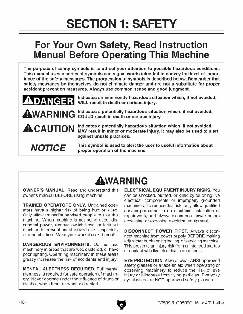
For Your Own Safety, Read Instruction Manual Before Operating This Machine
The purpose of safety symbols is to attract your attention to possible hazardous conditions. This manual uses a series of symbols and signal words intended to convey the level of impor-tance of the safety messages. The progression of symbols is described below. Remember that safety messages by themselves do not eliminate danger and are not a substitute for proper accident prevention measures. Always use common sense and good judgment.
Indicates a potentially hazardous situation which, if not avoided, MAY result in minor or moderate injury. It may also be used to alert against unsafe practices.
Indicates a potentially hazardous situation which, if not avoided, COULD result in death or serious injury.
Indicates an imminently hazardous situation which, if not avoided, WILL result in death or serious injury.
This symbol is used to alert the user to useful information about proper operation of the machine.NOTICE
SECTION 1: SAFETY

G0509 & G0509G 16" x 40" Lathe -11-
WEARING PROPER APPAREL. Do not wear clothing, apparel or jewelry that can become entangled in moving parts. Always tie back or cover long hair. Wear non-slip footwear to reduce risk of slipping and losing control or accidentally contacting cutting tool or moving parts.
HAZARDOUS DUST. Dust created by machinery operations may cause cancer, birth defects, or long-term respiratory damage. Be aware of dust hazards associated with each workpiece mate-rial. Always wear a NIOSH-approved respirator to reduce your risk.
HEARING PROTECTION. Always wear hear-ing protection when operating or observing loud machinery. Extended exposure to this noise without hearing protection can cause permanent hearing loss.
REMOVE ADJUSTING TOOLS. Tools left on machinery can become dangerous projectiles upon startup. Never leave chuck keys, wrenches, or any other tools on machine. Always verify removal before starting!
USE CORRECT TOOL FOR THE JOB. Only use this tool for its intended purpose—do not force it or an attachment to do a job for which it was not designed. Never make unapproved modifica-tions—modifying tool or using it differently than intended may result in malfunction or mechanical failure that can lead to personal injury or death!
AWKWARD POSITIONS. Keep proper footing and balance at all times when operating machine. Do not overreach! Avoid awkward hand positions that make workpiece control difficult or increase the risk of accidental injury.
CHILDREN & BYSTANDERS. Keep children and bystanders at a safe distance from the work area.Stop using machine if they become a distraction.
GUARDS & COVERS. Guards and covers reduce accidental contact with moving parts or flying debris. Make sure they are properly installed, undamaged, and working correctly BEFORE operating machine.
FORCING MACHINERY. Do not force machine. It will do the job safer and better at the rate for which it was designed.
NEVER STAND ON MACHINE. Serious injury may occur if machine is tipped or if the cutting tool is unintentionally contacted.
STABLE MACHINE. Unexpected movement dur-ing operation greatly increases risk of injury or loss of control. Before starting, verify machine is stable and mobile base (if used) is locked.
USE RECOMMENDED ACCESSORIES. Consult this owner’s manual or the manufacturer for rec-ommended accessories. Using improper acces-sories will increase the risk of serious injury.
UNATTENDED OPERATION. To reduce the risk of accidental injury, turn machine OFF and ensure all moving parts completely stop before walking away. Never leave machine running while unattended.
MAINTAIN WITH CARE. Follow all maintenance instructions and lubrication schedules to keep machine in good working condition. A machine that is improperly maintained could malfunction, leading to serious personal injury or death.
DAMAGED PARTS. Regularly inspect machine for damaged, loose, or mis-adjusted parts—or any condition that could affect safe operation. Immediately repair/replace BEFORE operating machine. For your own safety, DO NOT operate machine with damaged parts!
MAINTAIN POWER CORDS. When disconnect-ing cord-connected machines from power, grab and pull the plug—NOT the cord. Pulling the cord may damage the wires inside. Do not handle cord/plug with wet hands. Avoid cord damage by keeping it away from heated surfaces, high traffic areas, harsh chemicals, and wet/damp locations.
EXPERIENCING DIFFICULTIES. If at any time you experience difficulties performing the intend-ed operation, stop using the machine! Contact our Technical Support at (570) 546-9663.

-12- G0509 & G0509G 16" x 40" Lathe
No list of safety guidelines can be complete. Every shop environment is different. Always consider safety first, as it applies to your individual working conditions. Use this and other machinery with caution and respect. Failure to do so could result in serious per-sonal injury, damage to equipment, or poor work results.
Like all machinery there is potential danger when operating this machine. Accidents are frequently caused by lack of familiarity or failure to pay attention. Use this machine with respect and caution to lessen the pos-sibility of operator injury. If normal safety precautions are overlooked or ignored, seri-ous personal injury may occur.
1. UNDERSTANDING THE MACHINE: Read and understand this manual before operat-ing machine.
2. CLEANING MACHINE: To avoid entangle-ment and lacerations, do not clear chips by hand. Use a brush, and never clear chips while the lathe is operating.
3. USING CORRECT TOOLING: Always select the right cutter for the job, and make sure cutters are sharp. The right tool decreases strain on the lathe components and reduces the risk of unsafe cutting.
4. ELIMINATING PROJECTILE HAZARDS: Always remove the chuck key, and never walk away from the lathe with the chuck key installed. Always make sure workpiece is securely held in chuck before starting lathe. A workpiece thrown from the chuck could cause severe injury.
5. AVOIDING OVERLOADS: Always use the appropriate feed and speed rates.
6. PREVENTING A CUTTING TOOL/CHUCK CRASH: Always release automatic feeds after completing a job, and never leave lathe unattended while it is running.
7. AVOIDING STARTUP INJURIES: Make sure workpiece, cutting tool, and tool post have adequate clearance before starting lathe. Check chuck clearance and saddle clearance before starting the lathe. Make sure spindle RPM is set correctly for part diameter before starting the lathe. Large parts can be ejected from the chuck if the chuck speed is set too high.
8. CHUCK SAFETY: Chucks are surprisingly heavy and awkward to hold, so protect your hands and the lathe ways. Always use a chuck cradle or piece of plywood over the lathe ways.
9. WORKPIECE SUPPORT: Support a long workpiece if it extends from the headstock so it will not wobble violently when the lathe is turned ON. If workpiece extends more than 2.5 times its diameter from the chuck, support it by a center or steady rest, or it may deflect and fall out of the chuck while cutting.
10. AVOIDING ENTANGLEMENT INJURIES: Never attempt to slow or stop the lathe chuck or mill spindle by hand; and tie back long hair, ponytails, loose clothing, and sleeves so they do not dangle.
Additional Safety Instructions for Lathes

G0509 & G0509G 16" x 40" Lathe -13-
The following is a list of common definitions, terms and phrases used throughout this manual as they relate to this lathe and metalworking in general. Become familiar with these terms for assembling, adjusting or operating this machine. Your safety is VERY important to us at Grizzly!
Arbor: A machine shaft that supports a cutting tool.
Backlash: Wear in a screw or gear mechanism that may result in slippage, vibration, and loss of tolerance.
Carriage: A main housing that consists of the apron and the saddle.
Cross Slide: A fixture attached to the lathe car-riage that holds the compound rest and can be moved in and out.
Compound Rest: A fixture attached to the cross slide that holds the tool holder and can be moved in and out.
Cutting Speed: The distance that a point on a cutter moves in one minute, expressed in meters or feet per minute.
Dial Indicator: An instrument used in setup and inspection work that shows on a dial the amount of error in size or alignment of a part.
Facing: In lathe work, cutting across the end of a workpiece, usually to machine a flat surface.
Feed: The movement of a cutting tool into a workpiece.
Gib: A tapered wedge located along a sliding member to take up wear or to ensure a proper fit.
Headstock: The major lathe component that houses the spindle and motor drive system to turn the workpiece.
Lathe Center: A lathe accessory with a 60° point which is inserted into the headstock or tailstock of the lathe and is used to support the workpiece.
Leadscrew: The long screw that is driven by the end gears and supplies power to the carriage.
Saddle: The upper portion of carriage that rides on the lathe ways and supports the cross feed and the follow rest.
Spindle: The revolving shaft that holds and drives the workpiece.
Tailstock: A moveable fixture opposite of the headstock on a lathe that has a spindle used to support one end of a workpiece and for hold-ing tools.
Tool Post: The part of the compound rest that holds the tool holder.
Turret: A machine fixture that holds multiple tools and can be revolved and indexed to position.
Ways: The precision machined and flat tracks on which the carriage and tailstock slide.
Glossary of Terms
-14- G0509 & G0509G 16" x 40" Lathe
SECTION 2: CIRCUIT REQUIREMENTS
Serious personal injury could occur if you connect the machine to the power source before you have completed the set up pro-cess. DO NOT connect the machine to the power source until instructed to do so.
Full Load Amperage Draw w/PumpG0509 Low-Sp: 3HP 220V 3-Ph ........... 11 Amps High-Sp: 4HP 220V 3-Ph .......... 16 Amps
G0509G Low-Sp: 3.8HP 220V 3-Ph ....9.5 Amps High-Sp: 4.5HP 220V 3-Ph ..... 18 Amps
Circuit RequirementsWe recommend connecting your machine to a dedicated and grounded circuit that is rated for the amperage given below. Never replace a circuit breaker on an existing circuit with one of higher amperage without consulting a qualified electri-cian to ensure compliance with wiring codes. If you are unsure about the wiring codes in your area or you plan to connect your machine to a shared circuit, consult a qualified electrician.
Minimum Circuit .......................................30 Amp
220V Connection TypeFor 220V 3-phase connection of this lathe, we recommend wiring your machine with a L15-30 plug and recepticle. A qualified electrician should determine the best cord to use in your environ-ment.
G0509 & G0509G 220V 3-Phase ............ L15-30
GroundingIn the event of an electrical short, grounding reduces the risk of electric shock. The grounding wire in the power cord must be properly connected to the grounding prong on the plug; likewise, the outlet must be properly installed and grounded. All electrical connections must be made in accor-dance with local codes and ordinances.
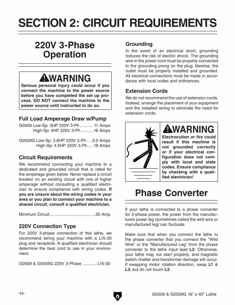
Electrocution or fire could result if this machine is not grounded correctly or if your electrical con-figuration does not com-ply with local and state codes. Ensure compliance by checking with a quali-fied electrician!
If your lathe is connected to a phase converter for 3-phase power, the power from the manufac-tured power leg (sometimes called the wild wire or manufactured leg) can fluctuate.
Make sure that when you connect the lathe to the phase converter that you connect the "Wild Wire" or the "Manufactured Leg" from the phase converter to the lathe input lead L2. Otherwise, your lathe may not start properly, and magnetic switch chatter and transformer damage will occur. If swapping motor rotation direction, swap L1 & L3, but do not touch L2.
Phase Converter
220V 3-PhaseOperation
Extension CordsWe do not recommend the use of extension cords. Instead, arrange the placement of your equipment and the installed wiring to eliminate the need for extension cords.
G0509 & G0509G 16" x 40" Lathe -15-
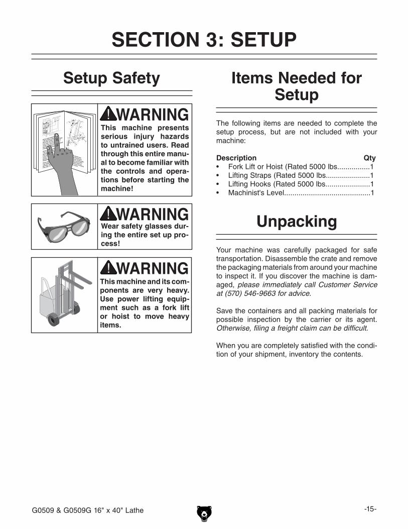
Wear safety glasses dur-ing the entire set up pro-cess!
This machine presents serious injury hazards to untrained users. Read through this entire manu-al to become familiar with the controls and opera-tions before starting the machine!
Setup Safety
SECTION 3: SETUP
This machine and its com-ponents are very heavy. Use power lifting equip-ment such as a fork lift or hoist to move heavy items.
The following items are needed to complete the setup process, but are not included with your machine:
Description Qty• Fork Lift or Hoist (Rated 5000 lbs................1• Lifting Straps (Rated 5000 lbs......................1• Lifting Hooks (Rated 5000 lbs......................1• Machinist's Level..........................................1
Items Needed for Setup
Your machine was carefully packaged for safe transportation. Disassemble the crate and remove the packaging materials from around your machine to inspect it. If you discover the machine is dam-aged, please immediately call Customer Service at (570) 546-9663 for advice.
Save the containers and all packing materials for possible inspection by the carrier or its agent. Otherwise, filing a freight claim can be difficult.
When you are completely satisfied with the condi-tion of your shipment, inventory the contents.
Unpacking

-16- G0509 & G0509G 16" x 40" Lathe
After all the parts have been removed from the shipping crate, you should have the following items with your lathe.
Installed Components (Figure 2) Qty.A. 8" Three-Jaw Chuck w/External Jaws ........ 1B. Steady Rest ................................................ 1C. Quick Change Tool Post w/Tool Holder ..... 1D. Follow Rest ................................................. 1
Loose Components (Figure 3)E. 12" Four-Jaw Universal Chuck ................... 1F. 14" Faceplate ............................................. 1G. Little Red Tool Box ..................................... 1H. Tool Holder (1 Installed) ............................. 2I. Wrench Set 6/7, 8/10, 9/11, 11/13, 12/14, 17/19, 22/24, and 27/30mm ....... 1 eaJ. Camlock T-Wrench ..................................... 1K. Tool Holder/Apron Lock T-Wrench ............. 1L. 4-Jaw Chuck T-Wrench .............................. 1M. 3-Jaw Chuck T-Wrench .............................. 1N. 4-Jaw Chuck Camlock Studs ..................... 6O. Oil Bottle ..................................................... 1P. MT#6 to MT#4 Spindle Sleeve Adapter .... 1Q. Cast-Iron Feet ............................................ 6R. Jacking Studs W/Nuts ................................ 6S. Hex Wrench Set 2, 2.5, 3, 4, 5, 6, 8, 10, and 12mm ....................................... 1 eaT. Spider Screws ............................................ 4U. #2 Phillips Screwdriver ............................... 1V. #2 Standard Screwdriver ............................ 1W. Tailstock Lock Lever .................................. 1X. Handwheel Handle Set ......................... 1 eaY. Carbide Tip Dead Center MT#4 ................. 1Z. Standard Tip Dead Center MT#4 ............... 1AA. Internal Jaws for Three-Jaw Chuck ........... 3
Figure 2. Installed components.
DA C
BInventory
NOTICESome hardware/fasteners on the inventory list may arrive pre-installed on the machine. Check these locations before assuming that any items from the inventory list are missing.
Figure 3. Packaged components.
EF
G
AA
M L J
K
I
S
H
R T
UVW
X
QP
N
O
Y,Z

G0509 & G0509G 16" x 40" Lathe -17-
Clean Up
The unpainted surfaces are coated with a waxy oil to prevent corrosion during shipment. Remove this protective coating with a solvent cleaner or citrus-based degreaser such as Grizzly’s G7895 Citrus Degreaser. To clean thoroughly, some parts must be removed.
Figure 4. Machine clearances and bolt pattern.
60"
80"
24"
Keep Workpiece Loading Area Unobstructed
Lathe
220V 3-Phase Supply
LeftFootprint
36"
14 "7/8
21 "1/2
46 "1/2
RightFootprint
20 "1/2
"7/8 Mounting Holes
Site Considerations
Floor LoadYour lathe is a heavy load distributed in a small footprint. Place this machine on concrete floors only. The floor MUST be level, or the lathe frame and ways may distort over time.
Placement LocationConsider existing and anticipated needs, service panel access, length of material to be loaded into the lathe, and space for auxiliary stands, work tables or other machinery when establishing a location for your lathe (see Figure 4 for minimum wall clearances).
Children and visitors may be seriously injured if unsuper-vised. Lock all entrances to the shop when you are away. DO NOT allow unsupervised children or visitors in your shop at any time!
Gasoline and petroleum products have low flash points and can explode or cause fire if used to clean machinery. DO NOT use these products to clean the machinery.
Many cleaning solvents are toxic if inhaled. Minimize your risk by only using these products in a well ventilated area.
-18- G0509 & G0509G 16" x 40" Lathe
Lifting & Moving the Lathe
This lathe can be placed on the included leveling studs and cast-iron feet. If the lathe must be se-cured to the floor, refer to a professional machine installer for options. In either case, the lathe must be sitting flat at each mounting point, and the ways must be perfectly level. The bed cannot be twisted or bent. If a misalignment condition arises, shim the lathe where it mounts to the floor, or adjust the feet studs until the bed and ways are in alignment as shown by precision machinist's levels.
Make sure the slings or chains are routed so when the lathe is lifted and the chains or straps are tight, the control rod, leadscrew, or feed rod are not bent. Remember, the headstock carries most of the weight of this machine (see Figure 5) for safe chain or strap routing and connection.
This lathe is an extremely heavy machine. Serious personal injury or death may occur if safe lifting and moving methods are not followed. Seek assis-tance from a professional rigger if you are unsure about your abilities or maximum load ratings of your lifting equipment.
Figure 5. Lifting rod setup for the lathe.
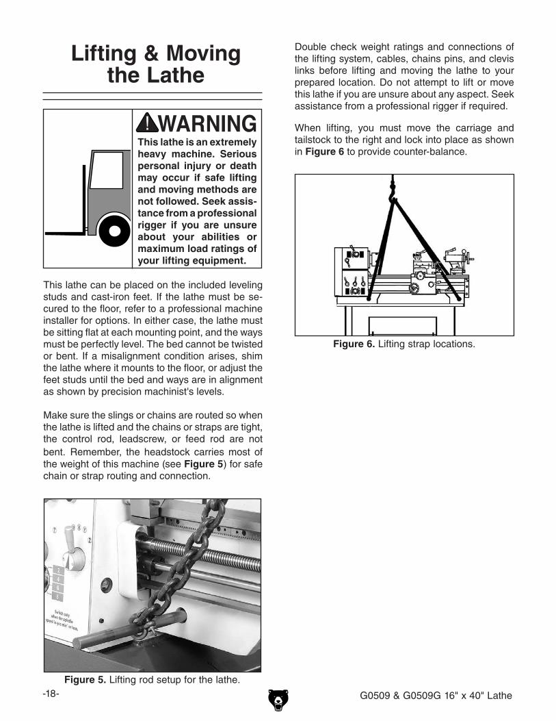
Figure 6. Lifting strap locations.
Double check weight ratings and connections of the lifting system, cables, chains pins, and clevis links before lifting and moving the lathe to your prepared location. Do not attempt to lift or move this lathe if you are unsure about any aspect. Seek assistance from a professional rigger if required.
When lifting, you must move the carriage and tailstock to the right and lock into place as shown in Figure 6 to provide counter-balance.
G0509 & G0509G 16" x 40" Lathe -19-
We recommend that the lathe is bolted to the floor. Because floor materials may vary, floor mounting hardware is not included. Since this is a precision machine, it is important to level the machine with a precision level when mounting.
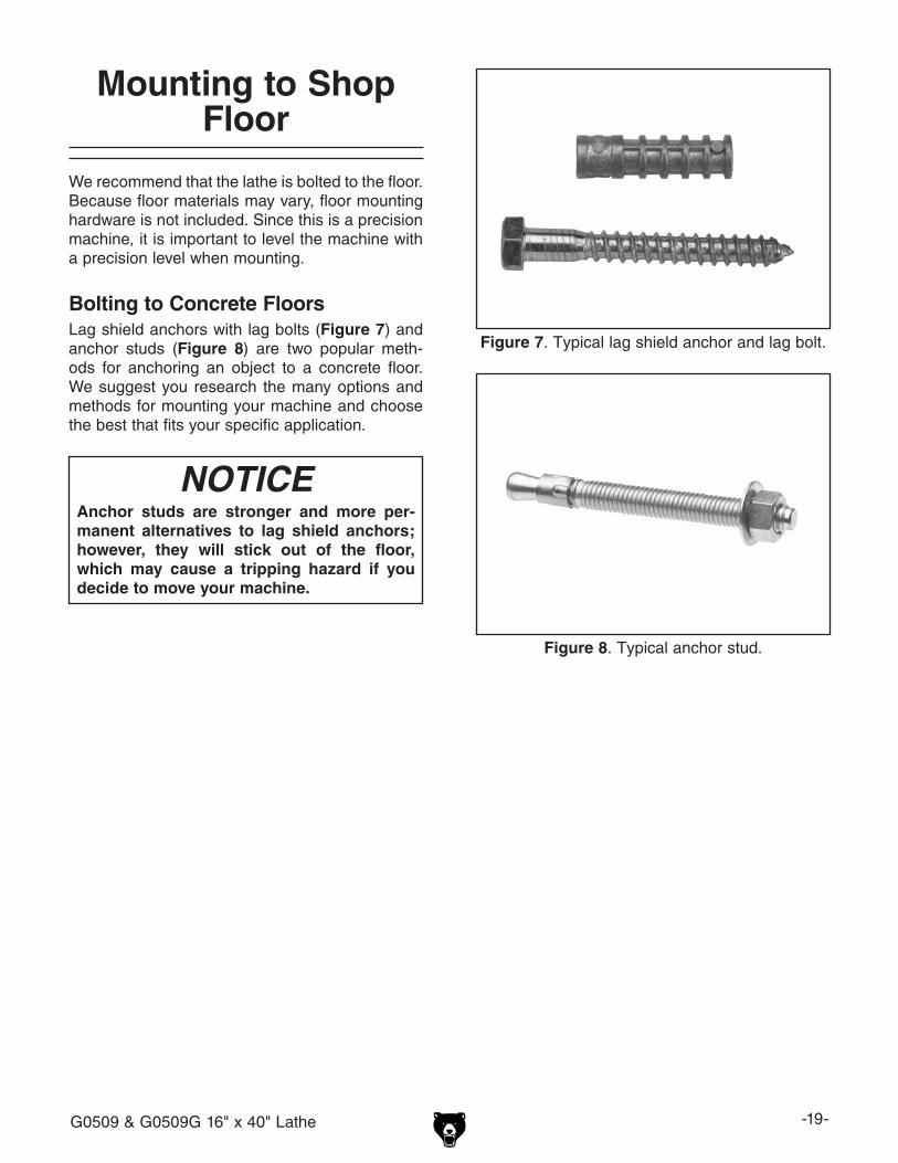
Bolting to Concrete FloorsLag shield anchors with lag bolts (Figure 7) and anchor studs (Figure 8) are two popular meth-ods for anchoring an object to a concrete floor. We suggest you research the many options and methods for mounting your machine and choose the best that fits your specific application.
Mounting to Shop Floor
Figure 7. Typical lag shield anchor and lag bolt.
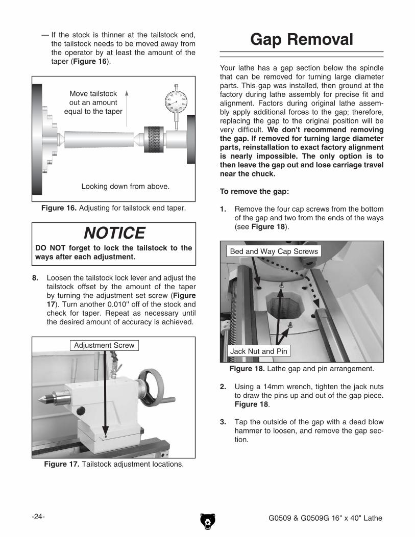
Figure 8. Typical anchor stud.
NOTICEAnchor studs are stronger and more per-manent alternatives to lag shield anchors; however, they will stick out of the floor, which may cause a tripping hazard if you decide to move your machine.

-20- G0509 & G0509G 16" x 40" Lathe
Test Run & Break-In
The purpose of the test run is to make sure the lathe and its safety features operate correctly. If you encounter any problems, stop the lathe and refer to Troubleshooting on Page 43 for corrections. To begin the test run & break-in procedure:
1. Make sure the lathe is lubricated and the headstock oil level is full. Refer to Lubrication on Page 40.
2. Make sure the chuck is correctly secured to the spindle. Refer to Chuck & Faceplate Mounting on Page 35 for details.
3. Disengage the feed and half-nut levers, and move the spindle ON/OFF lever to the neutral position, as shown in Figure 9.
NOTICENEVER shift lathe gears when lathe is operating, and make sure both the half-nut lever and the feed lever are disengaged before you start the lathe! Otherwise the lathe will feed the apron into the chuck or tailstock, causing severe lathe damage.
Figure 10. Motor high/low range switch.
Motor High/Low Range Switch:
1 = LowI = Off
2 = High
Green Power Lamp
Jog Button
Pump Switch
Emergency Stop Button
5. On the G0509G lathe, make sure the four spider bolts are either removed or they are tight in the spindle so they will not rattle out and contact the lathe end cover, causing damage when the lathe is running.
6. Make sure the pump switch (Figure 10) is in the OFF position, then turn the motor high/low range switch to "1". The green power lamp will glow.
7. Put on safety glasses, and tie back long hair, sleeves, and loose clothing.
8. Turn the work lamp ON and OFF to ensure it works correctly.
9. Point the coolant nozzles into the chip pan, turn the pump switch ON, make sure coolant flows, and then turn the pump switch OFF.
4. Twist the red emergency stop button (Figure 10) clockwise so it pops out.
Figure 9. Apron controls positioned for test run.
Feed Lever is Horizontal
(Disengaged)
Half-Nut Lever is Pulled Up
(Disengaged)
Spindle Rotation ON/OFF Lever in Central Position (Motor OFF)

G0509 & G0509G 16" x 40" Lathe -21-
12. Move the spindle rotation ON/OFF lever (Figure 9) down until the chuck begins to turn. The top of the chuck should turn toward you.
—If the chuck is rotating away from you, then you must complete the Changing Motor Rotation procedure on Page 22, and repeat the entire Test Run procedure.
13. Push the emergency stop button.
—If the lathe does not stop, move the spindle rotation ON/OFF lever to the central posi-tion (OFF), and disconnect the lathe from power. Refer to Troubleshooting on Page 43 for correction.
14. Return the spindle rotation ON/OFF lever to the central position (OFF), reset the emer-gency stop button, and restart the lathe.
15. Press down on the foot brake, and the lathe should come to a quick stop.
—If the lathe does not stop, push the emer-gency stop button, and disconnect the lathe from power. Refer to Troubleshooting on Page 43 for correction.
16. Return the spindle rotation ON/OFF lever to the center position, restart the lathe, and let the lathe run for a minimum of 10 minutes at 330 RPM in both directions. DO NOT LEAVE THE LATHE RUNNING UNATTENDED!
17. After 10 minutes, stop the lathe, and move the headstock speed levers to select the next highest RPM. Run the lathe in both directions for 10 minutes.
18. Repeat for the remaining RPM ranges pro-gressively increasing in RPM. When these steps are complete, the lathe is broken in.
19. Drain and refill the lubricant in the headstock. Refer to Lubrication on Page 40 for the pro-cedure and apron oil change interval.
Figure 11. Headstock controls.
Gearbox High/Low Lever Pointing Down
330 RPM
Selected with the Speed Lever
Speed Range Lever is Pointing to the Left
10. Push the jog button (Figure 10). The spindle motor will turn ON and the chuck will rotate.
11. Move the three headstock levers so they are positioned as shown in Figure 11. This will select a spindle speed of 330 RPM.

-22- G0509 & G0509G 16" x 40" Lathe
Changing Motor Rotation Disconnect the lathe from
power before working on wiring, and get help from an electrician if you are unsure about your wiring skills and codes. Electrocution or fire could result if this warning is ignored!
If the chuck turns up and away from you when the spindle lever is in the down position, phase polar-ity must be reversed. This is done by swapping the position of two of the three incoming power supply wires at the junction box.
To reverse phase polarity:
1. DISCONNECT LATHE FROM POWER!
2. Remove the junction box cover at the rear of the lathe and swap L1 and L3 input wires (see Figure 12).
3. Replace the junction box cover.
Figure 12. Location of L1 and L3 input wires.
TOPOWER CORD
TOELECTRICAL
BOX
PE
PE
1L31L21L1
L1 L2 L3
SwapTheseWires

G0509 & G0509G 16" x 40" Lathe -23-
Figure 13. Finished dead center.
The tailstock alignment was set at the factory with the headstock. However, we recommend that you take the time to ensure that the tailstock is aligned to your own desired tolerances.
To align the tailstock:
1. Center drill a 6'' long piece of bar stock on both ends. Set it aside for use in Step 4.
2. Make a dead center by turning a shoulder to make a shank. Flip the piece over in the chuck and turn a 60° point (Figure 13). As long as it remains in the chuck, the point of your center will be accurate to the spindle axis.
Note: Keep in mind that the point will have to be refinished whenever it is removed and returned to the chuck.
Figure 14. Bar stock mounted on centers.
3. Place the dead center in your tailstock.7. Measure the stock with a micrometer. If
the stock is wider at the tailstock end, the tailstock needs to be moved toward the cutter the amount of the taper (Figure 15).
Figure 15. Adjusting for headstock end taper.
Looking down from above.
5. Turn approximately 0.010" off the diameter.
6. Mount a dial indicator so that the plunger is on the tailstock barrel (Figure 15).
Tailstock Setup 4. Attach a lathe dog to the bar stock from Step 1 and mount it between the centers (as shown in Figure 14).
-24- G0509 & G0509G 16" x 40" Lathe
8. Loosen the tailstock lock lever and adjust the tailstock offset by the amount of the taper by turning the adjustment set screw (Figure 17). Turn another 0.010'' off of the stock and check for taper. Repeat as necessary until the desired amount of accuracy is achieved.
— If the stock is thinner at the tailstock end, the tailstock needs to be moved away from the operator by at least the amount of the taper (Figure 16).
Figure 16. Adjusting for tailstock end taper.
Looking down from above.
Figure 17. Tailstock adjustment locations.
NOTICEDO NOT forget to lock the tailstock to the ways after each adjustment.
Adjustment Screw
Gap Removal
Your lathe has a gap section below the spindle that can be removed for turning large diameter parts. This gap was installed, then ground at the factory during lathe assembly for precise fit and alignment. Factors during original lathe assem-bly apply additional forces to the gap; therefore, replacing the gap to the original position will be very difficult. We don't recommend removing the gap. If removed for turning large diameter parts, reinstallation to exact factory alignment is nearly impossible. The only option is to then leave the gap out and lose carriage travel near the chuck.
To remove the gap:
1. Remove the four cap screws from the bottom of the gap and two from the ends of the ways (see Figure 18).
2. Using a 14mm wrench, tighten the jack nuts to draw the pins up and out of the gap piece. Figure 18.
3. Tap the outside of the gap with a dead blow hammer to loosen, and remove the gap sec-tion.
Figure 18. Lathe gap and pin arrangement.
Bed and Way Cap Screws
Jack Nut and Pin
G0509 & G0509G 16" x 40" Lathe -25-
Operation Safety
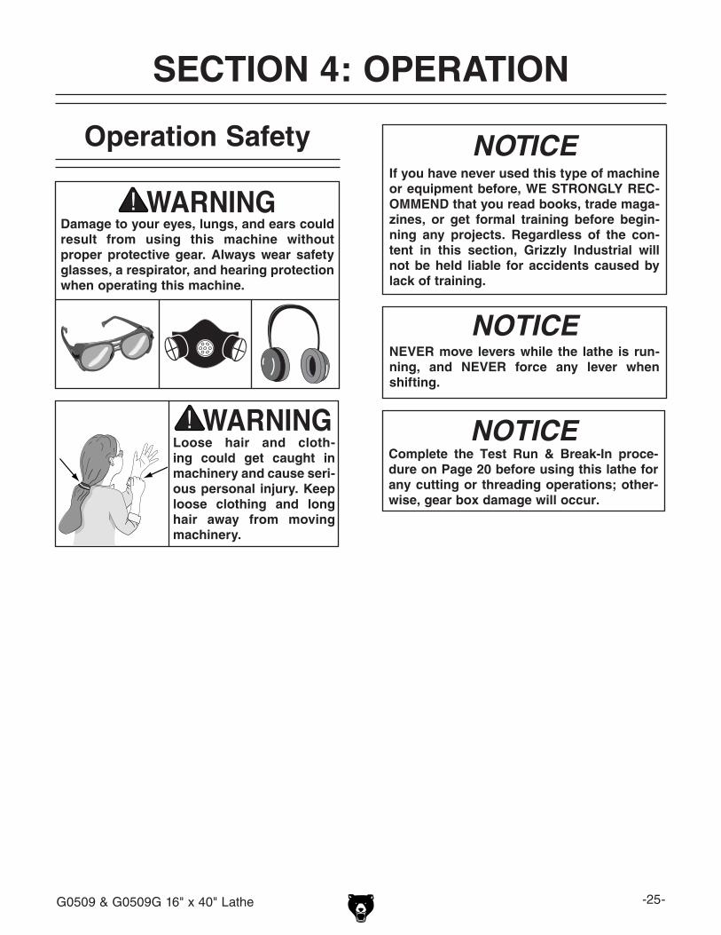
Damage to your eyes, lungs, and ears could result from using this machine without proper protective gear. Always wear safety glasses, a respirator, and hearing protection when operating this machine.
Loose hair and cloth-ing could get caught in machinery and cause seri-ous personal injury. Keep loose clothing and long hair away from moving machinery.
SECTION 4: OPERATION
NOTICEIf you have never used this type of machine or equipment before, WE STRONGLY REC-OMMEND that you read books, trade maga-zines, or get formal training before begin-ning any projects. Regardless of the con-tent in this section, Grizzly Industrial will not be held liable for accidents caused by lack of training.
Complete the Test Run & Break-In proce-dure on Page 20 before using this lathe for any cutting or threading operations; other-wise, gear box damage will occur.
NOTICE
NOTICENEVER move levers while the lathe is run-ning, and NEVER force any lever when shifting.

-26- G0509 & G0509G 16" x 40" Lathe
The spindle speed or RPM is controlled by two speed control levers at the top of the headstock and the 2-speed motor switch located on the lathe base (Figure 19). The 2-speed motor allows for the low and high range speed options presented in columns 1 and 2 shown in Figure 19. Below is an example how to set the spindle to 1800 RPM.
See Figure 19 for the following example:
1. Move the 2-speed motor switch so it points to position 1.
Note: Position "1" on the switch activates both #1 columns on the speed chart.
Position "2" activates both #2 columns on the speed chart.
Position "I", the central position on the switch, cuts power to the motor.
2. Move the spindle orange/blue range lever so it points to the right-hand orange-low range column number 1.
Note: The spindle orange/blue range lever
must point to which ever range column your RPM is listed in.
3. Move the spindle speed lever so the indica-tor points to 1800 at the bottom of the orange column number 1.
Note: The spindle speed lever must point to one of four speeds within the column in ques-tion.
Spindle Speeds
Figure 19. Spindle speed control.
Spindle Orange/Blue Range Lever
2-Speed Motor Switch
Spindle Speed Lever

G0509 & G0509G 16" x 40" Lathe -27-
Figure 20. Gearbox controls.
Gearbox Speed Range lever
The gearbox has a series of levers used for con-trolling the feed rod and leadscrew feed rates in relationship with the spindle speed. Based on the threading and feed rate chart, you can shift the gearbox to accommodate an elaborate array of feed rates.
NOTICEONLY shift the gearbox levers when spindle speed is less than 500 RPM and the gear-box speed range lever is in neutral. NEVER force a lever. If the lever will not engage, use the jog button when applicable so the teeth mesh and the lever drops into position.
Gearbox Speed Range Lever
-28- G0509 & G0509G 16" x 40" Lathe
Feed Rod and Leadscrew
Gearbox Ratio Levers
The leadscrew/feed rod lever (Figure 21) engag-es and disengages the leadscrew and feed rod simultaneously. When the lever is moved up or down, the rotation of the leadscrew and feed rods are simultaneously reversed.
The three-position gearbox high/low range lever (Figure 21) will put the gearbox into high range "H", low range "L", or neutral "I".
Note: Make sure to loosen the carriage lock (Figure 28) when apron power feed or threading are to be used. The carriage lock is used only to increase carriage stability when facing operations are in process.
NOTICEONLY shift the gearbox levers when spindle speed is less than 500 RPM and the gear-box speed range lever is in neutral. NEVER force a lever. If the lever will not engage, use the jog button when applicable so the teeth mesh and the lever drops into position.
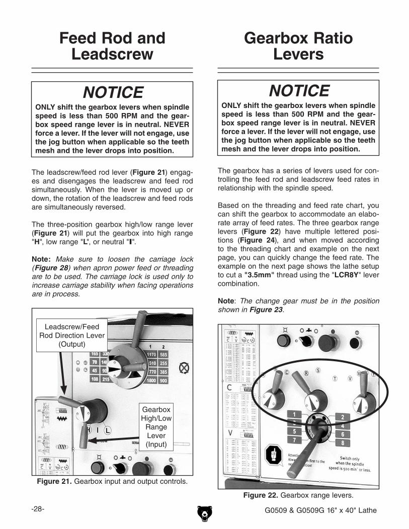
Figure 21. Gearbox input and output controls.
Leadscrew/Feed Rod Direction Lever
(Output)
Gearbox High/Low
Range Lever(Input)
Figure 22. Gearbox range levers.
NOTICEONLY shift the gearbox levers when spindle speed is less than 500 RPM and the gear-box speed range lever is in neutral. NEVER force a lever. If the lever will not engage, use the jog button when applicable so the teeth mesh and the lever drops into position.
The gearbox has a series of levers used for con-trolling the feed rod and leadscrew feed rates in relationship with the spindle speed.
Based on the threading and feed rate chart, you can shift the gearbox to accommodate an elabo-rate array of feed rates. The three gearbox range levers (Figure 22) have multiple lettered posi-tions (Figure 24), and when moved according to the threading chart and example on the next page, you can quickly change the feed rate. The example on the next page shows the lathe setup to cut a "3.5mm" thread using the "LCR8Y" lever combination.
Note: The change gear must be in the position shown in Figure 23.

G0509 & G0509G 16" x 40" Lathe -29-
Figure 24. General usage.
Figure 23. Change gear location.
LCR8Y=3.5mm

-30- G0509 & G0509G 16" x 40" Lathe
Power Feed Direction Knob
Your lathe can cut left or right while feeding or in and out when facing. The feed direction is con-trolled by the feed direction knob shown in Figure 26.
Figure 26. Feed direction knob.
Power Feed Direction Knob
Tool Post & Holder
Cutting tools can be secured and removed by tightening or loosening the clamping screws in the top of the tool holder (Figure 27). A threaded stud is mounted in the top of the holder and has a knurled thumb wheel. Rotating the thumb wheel raises or lowers the tool holder so the cutting tool can be indexed on the workpiece. The handle on the tool post is rotated to lock and unlock the tool holder, which rests in the dovetail ways. The tool post may be rotated by loosening the nut at the top of the tool post.
Figure 27. Quick change tool post.
Manual Feed Handwheels
Carriage Handwheel The carriage handwheel (Figure 25) moves the carriage left or right along the bed. Remember the carriage lock must be loosened to allow for carriage movement during manual and power fed operations.
Compound Slide HandwheelThe compound slide handwheel can adjust the cross slide at any angle. Angle adjustment is locked by two cap screws on the base of the top slide. The graduated dial can be rotated to read metric or inch conventions by turning it 180° degrees by holding the handwheel with one hand and turning the dial hub with the other.
Cross Slide HandwheelThe cross slide handwheel moves the cross slide toward and away from the work. Turning the dial clockwise moves the slide toward the workpiece. The graduated dial can be rotated to read metric or inch conventions by turning it 180° degrees by holding the handwheel with one hand and turning the dial hub with the other.
Figure 25. Handwheel locations.
Cross SlideHandwheel
Compound SlideHandwheel
Carriage Handwheel
Carriage Lock
Knurled Thumbwheel

G0509 & G0509G 16" x 40" Lathe -31-
The half-nut lever (Figure 28) clamps and releases the half-nut, which clamps around the leadscrew. The lever is only engaged while cutting threads and is not designed for general power feeding operations. For general purpose feeding, use the feed lever (Figure 28). This lathe uses inch lead-screws, and the thread dial chart shown in Figure 29 is only used for inch threading. For all other threading operations, the half nut lever must stay engaged until the threads are complete.
Note: If the apron feed lever (Figure 28), is engaged, the halfnut lever is blocked from use; and when the half-nut lever is engaged, the apron feed lever is blocked from use. If both levers are engaged at the same time, apron damage will occur.
When the thumb knob (Figure 28) is loosened, the thread dial housing pivots so its gear can be engaged or disengaged from the leadscrew. When engaged, the dial turns with the leadscrew and spindle.
Note: Always loosen the carriage lock (Figure 28) when threading or using the apron power feed. The carriage lock is used only to increase carriage stability during facing operations.
Half-Nut Lever and Thread Dial
Figure 29. Threading dial chart.
This column indicates when you can use the thread dial based on which thread TPI is being cut.
This column indicates which position on the thread dial you must reengage the halfnut.
Figure 28. Threading dial and half-nut lever.
Half-Nut Lever
Dial Thumb Knob
ThreadingDial Chart
Carriage Lock
ApronFeed Lever

-32- G0509 & G0509G 16" x 40" Lathe
Steady Rest
The steady rest supports long, small diame-ter stock that otherwise could not be turned because of deflection, and can be used instead of the tailstock when facing the end of a long workpiece.
On the G0509G, the brass wear pads at the ends of the fingers have been replaced with bearings. Having bearings here maintains consistent non-wearing support throughout the cut.
To use the steady rest:
1. Secure the steady rest to the bedway from below with the locking plate, then snug the mounting bolt (Figure 30).
The follow rest is normally used with small diam-eter stock to prevent the workpiece from “spring-ing” under pressure from the turning tool.
On the G0509G, the brass wear pads at the ends of the fingers have been replaced with bearings. Having bearings here maintains consistent non-wearing support throughout the cut. The steady rest can also replace the tailstock to allow for cut-ting tool access at the end of your workpiece.
To use the follow rest:
1. Secure the follow rest to the saddle with the two cap screws (Figure 31).
Follow Rest
Figure 30. Steady rest in place.
Mounting Bolt
2. Adjust the fingers until the bearings make contact and support the workpiece. Do not over tighten the fingers against the workpiece or you will cause workpiece deflection.
3. Oil the finger bearings and the rolling surfaces while in use to create non-marring workpiece support and to reduce finger wear.
Figure 31. Follow rest secured to saddle.

G0509 & G0509G 16" x 40" Lathe -33-
Centers
A tailstock center supports stock that is too long to be supported by the chuck alone. The tailstock barrel and dead center have an MT#4 taper. Included with this lathe is an MT#4 to MT#6 spin-dle adapter sleeve. If you need to install a center in the spindle when using the face plate, you can do so by using this adapter sleeve.
Before installing a center or arbor, make sure that the mating surfaces are perfectly clean. These parts will last longer and remain accurate if prop-erly maintained. If oil is present on the mating surfaces, the tapers will not interlock.
To install the center, insert the end of it into the tailstock bore until it seats. Once the workpiece is installed, the force of a mounted workpiece will fully seat the taper.
When using a dead center (Figure 33), the tailstock barrel should protrude about 1⁄2" and not more than 23⁄4" as indicated by the scale on the barrel.
To remove the dead center, back the tailstock barrel all the way into the tailstock casting. The dead center will pop out. Be sure to catch it when it comes out to avoid damaging the tip.
Figure 33. Dead center installed in tailstock.
Tailstock Controls
The tailstock (Figure 32) serves many func-tions. The primary use is holding centers and drill chucks. The barrel has an MT#4 (morse taper #4) bore and is imprinted with graduations in millime-ters and inches.
Figure 32. Tailstock controls.
Tailstock HandwheelTurning the handwheel advances or retracts the barrel in the tailstock. The graduated dial on the handwheel is adjustable.
Barrel Lock LeverThis lever locks the tailstock barrel in place.
Side Lock Lever & Torque Tightening (G0509G)This removable lever locks the tailstock in place on the lathe bed. The socket that it fits into will accept a 1⁄2-inch drive torque wrench.
To repeat very accurate vertical alignment posi-tioning, tighten the tailstock here with an inch-pound torque wrench. If you must, you can use a foot-pound torque wrench but DO NOT exceed 40 lbs/ft of torque or you may damage the ways and the tailstock. When tightening the tailstock down to the maximum torque of 40 lbs/ft, the center point will be drawn down approximately 0.006" from the normal centerline when the tailstock is resting free on the ways.
Side Lock Lever
Barrel Lock Lever
Tailstock Handwheel
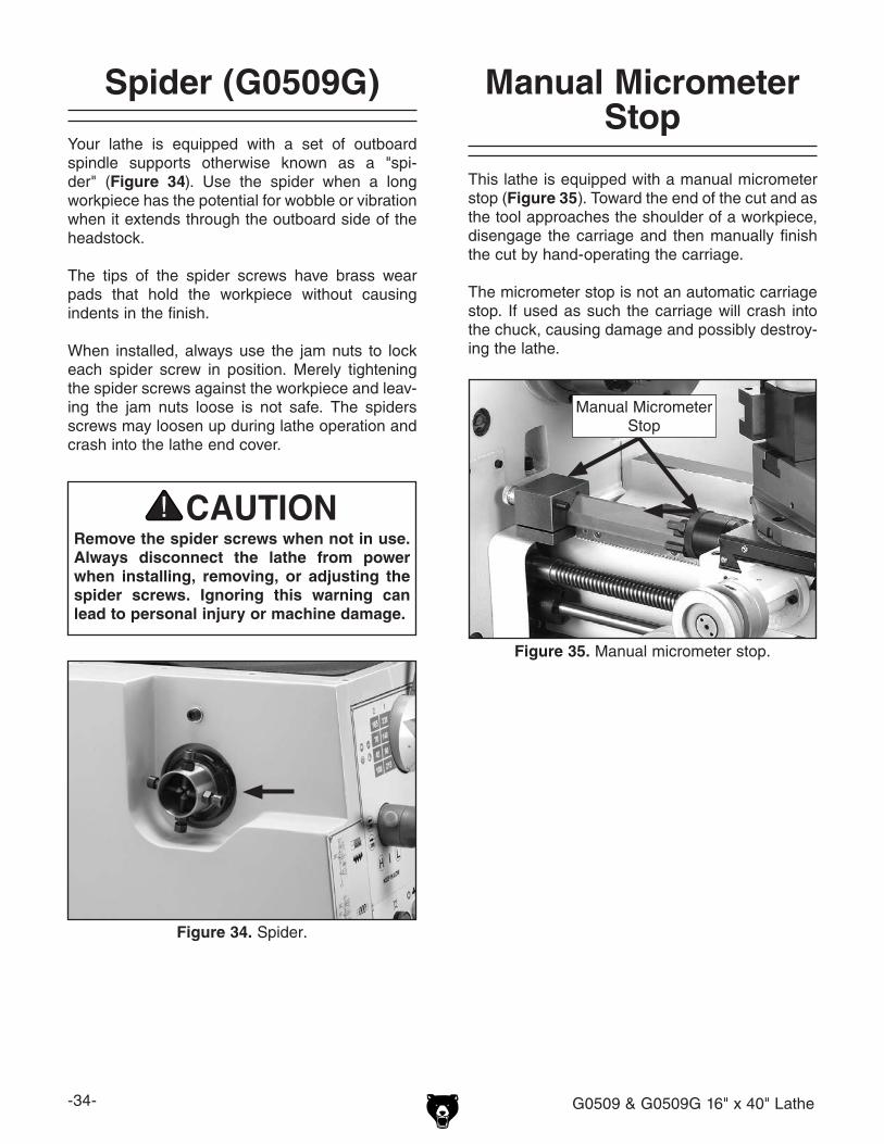
-34- G0509 & G0509G 16" x 40" Lathe
Spider (G0509G)
Your lathe is equipped with a set of outboard spindle supports otherwise known as a "spi-der" (Figure 34). Use the spider when a long workpiece has the potential for wobble or vibration when it extends through the outboard side of the headstock.
The tips of the spider screws have brass wear pads that hold the workpiece without causing indents in the finish.
When installed, always use the jam nuts to lock each spider screw in position. Merely tightening the spider screws against the workpiece and leav-ing the jam nuts loose is not safe. The spiders screws may loosen up during lathe operation and crash into the lathe end cover.
Remove the spider screws when not in use. Always disconnect the lathe from power when installing, removing, or adjusting the spider screws. Ignoring this warning can lead to personal injury or machine damage.
Figure 34. Spider.
Manual Micrometer Stop
This lathe is equipped with a manual micrometer stop (Figure 35). Toward the end of the cut and as the tool approaches the shoulder of a workpiece, disengage the carriage and then manually finish the cut by hand-operating the carriage.
The micrometer stop is not an automatic carriage stop. If used as such the carriage will crash into the chuck, causing damage and possibly destroy-ing the lathe.
Figure 35. Manual micrometer stop.
Manual Micrometer Stop

G0509 & G0509G 16" x 40" Lathe -35-
To remove a chuck or faceplate:
1. DISCONNECT LATHE FROM POWER!
2. Place a piece of plywood across the lathe ways and position it just under the chuck so the ways are protected.
3. Turn a cam with the chuck key until the cam lock mark aligns with the cam release datum line shown in Figure 37.
Chuck & FaceplateMounting
This lathe is shipped with the 3-jaw chuck installed. This is a scroll-type chuck, meaning that all three jaws move in unison when adjusted.
The 4-jaw chuck, on the other hand, features independent jaws. This chuck is used for square or unevenly-shaped stock.
If either chuck cannot hold your workpiece, the cast-iron faceplate has slots for T-bolts that hold standard or custom clamping hardware. With the correct clamping hardware, this faceplate will hold non-cylindrical parts such as castings.
The chucks and faceplate have a D-6 Camlock mount. Please note that there are lines stamped into the cam and on the chuck body. A chuck key is used to turn the locking cams (Figure 37) to secure/unsecure the chuck/faceplate.
Figure 37. Cam and lock marks.
Cam Release Datum Line
4. Unlock the other cams in the same manner. Make sure to support the chuck as you align the last cam. The chuck may come off at this point, so it is important that the weight is supported by an adequate chuck cradle.
5. Remove the chuck key.
—If the chuck is still tight on the spindle, tap the back of the chuck with a rubber or wood mallet while supporting the bottom of the chuck.
—If the chuck does not immediately come off, rotate the spindle approximately 60˚ and tap again. Make sure all the marks on the cams and spindle are in proper alignment.
The chuck is heavy and is awkward to han-dle. Always protect the ways when remov-ing or installing a chuck, and make sure that you make a support cradle (Figure 36). Use this cradle when installing or removing chucks. Ignoring this warning may lead to a severe crushing or amputation injury!
Figure 36. Wooden chuck support cradle.
Cam Lock Mark

-36- G0509 & G0509G 16" x 40" Lathe
To install a chuck or faceplate:
1. DISCONNECT LATHE FROM POWER!
2. Place a piece of plywood across the lathe ways and position it just under the chuck.
3. Place the chuck on the cradle.
4. Make sure the chuck taper and spindle taper mating surfaces are perfectly clean.
5. Inspect and make sure that all camlock studs are undamaged, are clean and lightly oiled, and that the camlock stud cap screws are in place and snug.
NOTICENever install a chuck or faceplate without having the camlock cap screws in place or fully tightened. If you ignore this notice, once installed the chuck may never be able to be removed since the camlock studs will turn with the camlocks and never release.
6. Align the chuck-to-spindle timing marks (Figure 39), and slide the chuck onto the spindle.
7. Turn a camlock with the chuck key until the cam line falls between the "V" marks (Figure 38).
Figure 38. Cam and lock marks.
Cam Release Datum Line
Cam Lock Mark
V's
8. Lock the other cams in a star pattern so the chuck is drawn up evenly on all sides without any chance of misalignment.
Note: If any of the cam lock marks (Figure 38) do not fall between the "V" marks when the cam lock is tight, you must adjust the offend-ing camlock stud as discussed in Camlock Stud Adjustment on Page 37.
9. Remove the chuck key.

G0509 & G0509G 16" x 40" Lathe -37-
Camlock Stud Adjustment
When fitting a chuck or faceplate with camlock studs, or when mounting a new chuck or face-plate, it may be necessary to adjust the camlock studs.
In order to properly install or adjust one or more camlock studs, you must remove a stud locking cap screw, then thread the camlock stud in or out until the line on the side of the stud is flush with the top of the chuck casting (Figure 39). This is an initial adjustment.
When you place the chuck onto the lathe spindle, you may find that one or more camlocks do not fully point between the "V" marks on the chuck.
INCORRECT CORRECT
Between Arrows
Turn Stud In One Turn
INCORRECT
Turn Stud Out One Turn
CamRelease Datum
Camlock Stud
Camlock Cap Screw is Tight But Camlock Stud Can Still Rotate Back and Forth Slightly
Initial Adjustment: Camlock Stud
Alignment Groove is Flush with Chuck
Surface
CHUCK
Chuck-to-Spindle Timing Mark
Figure 39. Camlock stud alignment.
If this is the case, you will have to remove the chuck and fine-tune the camlock stud adjustment. See Figure 39 for which direction to turn the camlock studs.
Once you have adjusted the camlock studs, install the chuck or faceplate as outlined in To Install Chuck or Faceplate on Page 36.
NOTICENever install a chuck or faceplate without having the camlock cap screws in place or fully tightened. If you ignore this notice, the chuck may never be able to be removed since the camlock studs will turn with the camlocks and never release.

-38- G0509 & G0509G 16" x 40" Lathe
SECTION 5: ACCESSORIESACCESSORIES
G7978—15 HP/12 HP Start, Phase ConverterAdd 3-phase electrical supply with this rota-ry phase converter! Operate single or multiple motors, transformers, and resistance loads at 100% power and 95% efficiency while saving big dollars at cheaply metered, single-phase electri-cal rates. For application assistance, please call our technical support group at (570) 546-9663.
Figure 43. Typical Rotary Phase Converter
H2670—HSS Square Tool Bits ½" x ½" x 4Our ground tool bits are M-2 HSS, making them some of the most durable tool bits around. Make your own specialized cutters in any shape using a silicon carbide grinding wheel (G8235-37) on your grinder.
Figure 40. H2670 HSS Square Tool Bits.
Figure 41. H5687 Pre-Ground Tool Bit Set.
H5687—8-Pc. Pre-Ground Tool Bit SetTired of grinding your blank high speed steel tool bits? We've done it for you! 8-pc set comes with these sharpened profiles: offset right and left hand tools with chip breaker, straight and chip breaker style threading tools, internal threading tool, part-ing tool, boring tool and turning tool. These tool bits are evenly hardened to better than 64C.
G9777—20-Pc. Carbide Tipped Tool Bit SetAn exceptional value for carbide lathe tool bits! This twenty-piece set offers tremendous savings over bits sold individually, plus every type is dupli-cated and ready at hand when you need it. The carbide is C-6 grade for cutting steel and alloys.
Figure 42. G9777 20 Pc. Carbide Tool Set.

G0509 & G0509G 16" x 40" Lathe -39-
G7038Z—Boring BarG7040—Carbide Inserts for Steel (5 pk)G7048—Carbide Inserts for Cast Iron (5 pk)
Figure 47. G7038Z Boring Bar.
G7030—Threading Tool HolderG7041—Carbide Inserts for Steel (5 pk)G7049—Carbide Inserts for Cast Iron (5 pk)
Figure 48. G7030 Threading Tool Holder.
G7033—Internal Threading Tool HolderG7042—Carbide Inserts for Steel (5 pk)G7050—Carbide Inserts for Cast Iron (5 pk)
Figure 49. G7033 Int. Threading Tool Holder.
Quick Change Tool HoldersAll models below are Series 300G5708—Boring Bar Holder, 3⁄4" & 1" BarG5711—Parting Tool Holder, 3⁄4" ToolG5712—Knurling Tool Holder, 1⁄2"~ 3⁄4" ToolG5710—Morse Taper Holder, MT#4 TaperG5707—Turning/Boring Holder, 1⁄2"~3⁄4" BitsG5706—Turning Holders, 1⁄2"~3⁄4" Bits
Figure 44. Series 300 quick change tool holders.
G5708 G5711 G5712
G5710 G5707 G5706
H5787—MT#4 x 5" Bull Nose Rolling CenterBuilt with precision sealed bearings, designed for heavy-duty use on hollow workpieces.
Figure 45. MT#4 bull nose rolling centers.
G9889—MT#4 Long Nose Precision CenterProvides critical tool clearance. Adjustable thrust bearings, 60° tip and 30° clearance relief angle.
Figure 46. MT#4 Long Nose Center
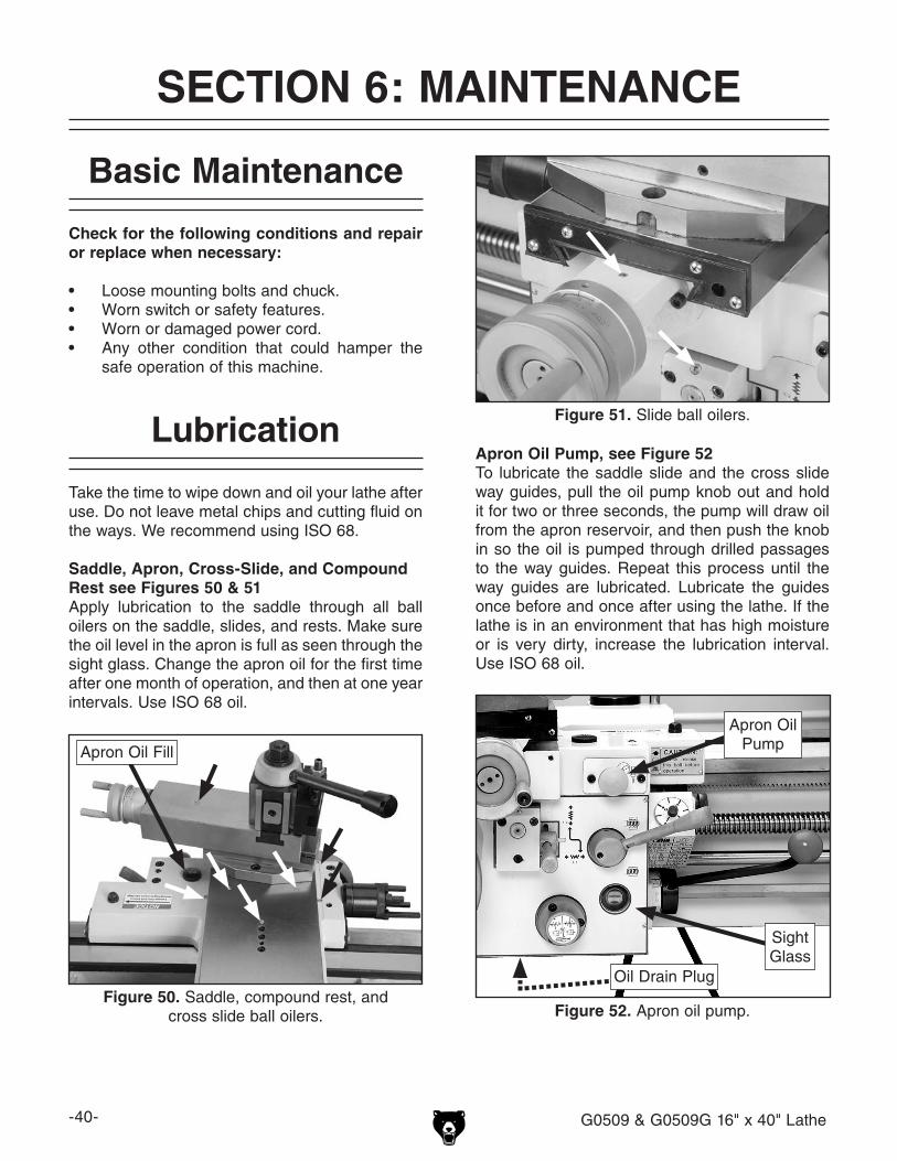
-40- G0509 & G0509G 16" x 40" Lathe
SECTION 6: MAINTENANCE
Check for the following conditions and repair or replace when necessary:
• Loose mounting bolts and chuck.• Worn switch or safety features.• Worn or damaged power cord.• Any other condition that could hamper the
safe operation of this machine.
Basic Maintenance
Lubrication
Take the time to wipe down and oil your lathe after use. Do not leave metal chips and cutting fluid on the ways. We recommend using ISO 68.
Saddle, Apron, Cross-Slide, and Compound Rest see Figures 50 & 51Apply lubrication to the saddle through all ball oilers on the saddle, slides, and rests. Make sure the oil level in the apron is full as seen through the sight glass. Change the apron oil for the first time after one month of operation, and then at one year intervals. Use ISO 68 oil.
Figure 51. Slide ball oilers.
Figure 50. Saddle, compound rest, and cross slide ball oilers.
Apron Oil Fill
Apron Oil Pump, see Figure 52To lubricate the saddle slide and the cross slide way guides, pull the oil pump knob out and hold it for two or three seconds, the pump will draw oil from the apron reservoir, and then push the knob in so the oil is pumped through drilled passages to the way guides. Repeat this process until the way guides are lubricated. Lubricate the guides once before and once after using the lathe. If the lathe is in an environment that has high moisture or is very dirty, increase the lubrication interval. Use ISO 68 oil.
Apron Oil Pump
Figure 52. Apron oil pump.
Sight Glass
Oil Drain Plug

G0509 & G0509G 16" x 40" Lathe -41-
Leadscrew, Feed Rod, Slides, and Ways, see Figure 55Be sure to clean and lubricate the leadscrew, feed rod and switch control rod. The leadscrew and feed rod have a bearing on the tail stock end support that requires one to two squirts of oil. Apply oil to the ways and slides after each use. Wipe the ways with a clean rag prior to lubrication to ensure that no grime is carried along with your lubricant into friction-sensitive areas. Applying oil to the bedways and other bare metal parts also protects the lathe from rust and pitting. Use ISO 68 oil in ball oilers and for wiping down the bedways and other metal parts.
External Gearing, Headstock and Gearbox, see Figure 53Brush on a coat of lithium grease on the teeth of the drive gears. Avoid getting grease on the belt or pulleys when lubricating. Change the oil in the headstock and gearbox after the first 2 hours of use; then, every 6 months depending on usage. Use ISO 32 oil in the headstock, and ISO 68 oil in the gearbox.
Note: The headstock oil fill plug is located on the top of the headstock plate, labeled OIL.
Figure 55. General lubrication.
Leadscrew
Feed Rod
Switch Control Rod
Ball Oilers
Rack
Way
Figure 53. Headstock lubrication.
Gearbox Fill
Gearbox Drain
Headstock Drain
Tailstock, see Figure 54The tailstock is fitted with two ball oilers. The tailstock barrel may be oiled directly. Apply oil each week, or after every few uses (depending on the frequency of operation). Be sure to clean the slide ways for the tailstock and lift the tailstock and squirt a few drops of oil on the ways. It is a good idea to remove the tailstock once a month and wipe the bottom thoroughly and relubricate the way tracks. Use ISO 68 oil.
Figure 54. Tailstock lubrication.

-42- G0509 & G0509G 16" x 40" Lathe
Coolant System
The coolant pump and reservoir are located in the base behind the vented cover on the tailstock end of the lathe.
The chip pan is fitted with a screen, so pay atten-tion that it does not become clogged, fill the chip pan with coolant, and cause the pump to operate in an empty reservoir. Pump damage will cccur if it is run for a period of time without coolant.
To perform regular maintenance on the cut-ting fluid system:
1. Remove the access cover at the rear of the lathe (Figure 56).
Figure 56. Coolant pump and reservoir.
2. Pump the old cutting fluid out of the reservoir and dispose of according to state and federal environmental laws.
3. Using a magnet, brush, and rags, clean out metal chips from the bottom of the reservoir and the screen. Flush with hot soapy water if required.
4. Refill the reservoir with applicable water-soluble cutting fluid. Closely follow the fluid manufacturer's instructions for mixing.
5. Open the valve on the coolant nozzle.
6. Turn the coolant pump ON (Figure 57) to prime the coolant system and to see if the coolant is cycling properly.
7. Replace the access cover.
BIOLOGICAL & POISON HAZARD! Use the correct personal protection equipment when handling cutting fluid and by follow federal, state, and fluid manufacturer requirements to properly dispose of cutting fluid.
Figure 57. Coolant pump switch.

G0509 & G0509G 16" x 40" Lathe -43-
Symptom Possible Cause Possible SolutionMotor will not start.
1. Main power panel switch is OFF.2. Emergency switch is pushed in.3. Spindle rotation switch at fault.
4. Circuit breaker or fuse has tripped.
5. No voltage or open connection.
6. Motor direction switch is at fault.7. Power switch or magnetic contactor is at
fault.8. Motor is at fault.
1. Turn the main power panel switch ON.2. Emergency switch is pushed in.3. Rotate the switch so it points to 1 or 2, or replace
bad switch.4. Seek an electrician to troubleshoot and repair the
shop power supply.5. Test circuit, replace wires and connections as
required.6. Replace switch.7. Replace power switch or magnetic contactor.
8. Replace motor.
Fuses or circuit breakers trip open.
1. Short circuit in line cord or plug.
2. Short circuit in motor or loose connections.
3. Incorrect fuses or circuit breakers in power supply.
1. Inspect cord or plug for damaged insulation and shorted wires.
2. Inspect all connections on motor for loose or shorted terminals or worn insulation.
3. Install correct fuses or circuit breakers.
Machine is loud, belt slips, or bogs down during a cut.
1. Excessive depth of cut.2. RPM or feed rate wrong for operation.3. Dull cutters.4. Belt is slipping.
5. Belt is at fault.
1. Decrease depth of cut.2. Refer to RPM feed rate chart for appropriate rates.3. Sharpen or replace cutters.4. Remove grease or oil on belt or pulleys/tighten belt
tensioner against low range belt.5. Replace belt.
Gear change levers will not shift into position.
1. Gears not aligned in headstock. 1. Rotate spindle by hand until gear falls into place.
Loud, repetitious noise coming from machine at or near the motor.
1. Pulley set screws or keys are missing or loose.
2. Motor fan is hitting the cover.
1. Inspect keys and set screws. Replace or tighten if necessary.
2. Tighten fan or shim cover, or replace items.
Motor is loud when cutting. Overheats or bogs down in the cut.
1. Excessive depth of cut or feed rate.2. RPM or feed rate wrong for cutting operation.3. Cutting tool is dull.4. Gear setup is too tight, causing them to bind.
1. Decrease depth of cut or feed rate.2. Refer to RPM feed rate chart for appropriate rates.3. Sharpen or replace the cutting tool.4. Readjust the gear setup with a small amount of
backlash so the gears move freely and smoothly when the chuck is rotated by hand.
Troubleshooting
Motor & Gearbox
Review the troubleshooting and procedures in this section to fix your machine if a problem develops. If you need replacement parts or you are unsure of your repair skills, then feel free to call our Technical Support at (570) 546-9663.
SECTION 7: SERVICE

-44- G0509 & G0509G 16" x 40" Lathe
Symptom Possible Cause Possible SolutionEntire machine vibrates exces-sively upon startup and while running.
1. Workpiece is unbalanced.
2. Worn or broken gear present.3. Chuck or faceplate has become unbalanced.
4. Spindle bearings at fault.
1. Reinstall workpiece so it is as centered with the spindle bore as possible.
2. Inspect gears and replace if necessary.3. Rebalance chuck or faceplate; contact a local
machine shop for help.4. Tighten or replace spindle bearings.
Cutting tool or machine com-ponents vibrate excessively dur-ing cutting.
1. Tool holder not tight enough.2. Cutting tool sticks too far out of tool holder;
lack of support.3. Gibs are out of adjustment.4. Dull cutting tool.5. Incorrect spindle speed or feed rate.
1. Check for debris, clean, and retighten.2. Reinstall cutting tool so no more than 1/3 of the total
length is sticking out of tool holder.3. Tighten gib screws at affected component.4. Replace or re-sharpen cutting tool.5. Use the recommended spindle speed.
Can't remove tapered tool from tailstock quill.
1. Quill was not retracted all the way back into the tailstock.
2. Debris was not removed from taper before inserting into quill.
1. Turn the quill handwheel until it forces taper out of quill.
2. Always make sure that taper surfaces are clean.
Cross slide, com-pound rest, or carriage feed has sloppy operation.
1. Gibs are out of adjustment.2. Handwheel is loose.3. Leadscrew mechanism worn or out of adjust-
ment.
1. Tighten gib screw(s).2. Tighten handwheel fasteners.3. Tighten any loose fasteners on leadscrew mecha-
nism.
Cross slide, compound rest, or carriage feed handwheel is hard to move.
1. Carriage lock is engaged.2. Gibs are loaded up with shavings or grime.
3. Gib screws are too tight.
4. Backlash setting too tight (cross slide only).
5. Bedways are dry.
1. Loosen the carriage lock.2. Remove gibs, clean ways/dovetails, lubricate, and
readjust gibs.3. Loosen gib screw(s) slightly, and lubricate
bedways.4. Slightly loosen backlash setting by loosening the
locking screw and adjusting the spanner ring at the end of the handle.
5. Lubricate bedways and handles.
Bad surface fin-ish.
1. Wrong RPM or feed rate.2. Dull tooling or poor tool selection.
3. Too much play in gibs.4. Tool too high.
1. Adjust for appropriate RPM and feed rate.2. Sharpen tooling or select a better tool for the intend-
ed operation.3. Tighten gibs.4. Lower the tool position.
Inaccurate turn-ing results from one end of the workpiece to the other.
1. Headstock and tailstock are not properly aligned with each other.
1. Realign the tailstock to the headstock spindle bore center line.
Chuck jaws won't move or don't move easily.
1. Chips lodged in the jaws. 1. Remove jaws, clean and lubricate chuck threads, and replace jaws.
Carriage won't feed, or hard to move.
1. Gears are not all engaged or broken.2. Gibs are too tight.3. Loose screw on the feed handle. 4. Leadscrew shear pin has sheared.
1. Adjust gear positions or replace.2. Loosen gib screw(s) slightly.3. Tighten.4. Correct for cause of shear pin breakage, and
replace shear pin.
Tailstock quill will not feed out of tailstock.
1. Quill lock lever is tightened down. 1. Turn lever counterclockwise.
Operation and Work Results
Troubleshooting

G0509 & G0509G 16" x 40" Lathe -45-
Compound Gib, see Figure 59The gib on the compound is adjusted by the same method as the gibs on the cross-slide, except the screw closest to the operator (when the com-pound slide is aligned with the cross slide) must be loosened and the screw furthest from the operator tightened to make the gib tighter.
Figure 59. Adjusting the compound rest gib.
Figure 58. Adjusting the cross-slide gib.
There are three main gib adjustments for the lathe. They are: the cross-slide gib, the compound slide gib, and the saddle gib.
Cross-slide Gib, see Figure 58The gib on the cross-slide is adjusted by the two screws located at each end. To adjust, loosen the set screw located along the edge of the cross-slide. This set screw is provided for locking the slide for certain operations. After making the adjustments detailed below, tighten the set screw until it just touches the gib.
The gib is wedge shaped and by loosening the screw closest to the operator and then tightening the opposite screw, the slide will become looser. Conversely, loosening the screw farthest away from the operator and tightening the closer screw will tighten the gib. Do not over tighten.
Adjust the gib so that it creates a slight drag when the slide is in motion. Test the ease of motion with the gib slightly loose. Begin tightening the gib and test after making small adjustments. When a slight drag is detected the gib is properly adjusted.
Gibs
NOTICEWhen adjusting gibs, keep in mind that the goal of gib adjustment is to remove unnec-essary sloppiness from the slide movement without causing them to bind. Loose gibs may cause poor finishes on the workpiece. Over tightening may cause premature wear.
Gib Screw
Gib Screw
Set Screw
Set Screw

-46- G0509 & G0509G 16" x 40" Lathe
Saddle Gib and Carriage Lock, see Figure 60Located at the back side of the saddle, the saddle gib is adjusted by the same method as the gibs on the cross-slide and compound rest. However, you must make sure that you loosen the carriage lock bolt. This bolt is used to lock the carriage in place for increased rigidity when making face cuts.
It is important that the saddle gib be properly adjusted. A loose gib will cause finish problems in a workpiece. A gib adjusted too tightly will cause premature wear.
Figure 60. Carriage lock bolt.
Carriage Lock Bolt
Cross Slide Leadscrew Adjustment
Figure 61. Cross slide backlash adjustment socket head cap screws.
Cap Screws
Backlash is the amount of play found in a leadscrew. It can be found by turning the cross slide handwheel in one direction, then turning the handwheel the other direction. When the cross slide begins to move, the backlash has been taken up.
Note: Avoid the temptation to overtighten the cross slide backlash screw. Overtightening will cause excessive wear to the sliding block and leadscrew. Reducing backlash to less than 0.010" is impractical and reduces cross slide life.
Backlash is adjusted by tightening or loosening the cap screws shown in Figure 61. These screws draw a wedge-type nut against the leadscrew and main nut. If you get the gib too tight, loosen the cap screws a few turns, tap the cross slide a few times with a rubber or wooden mallet, and turn the handle slowly back and forth until the handle turns freely. To readjust the backlash, rock the handle back and forth, and tighten the screw slowly until the backlash is at approximately 0.010" as indi-cated on the handwheel dial.
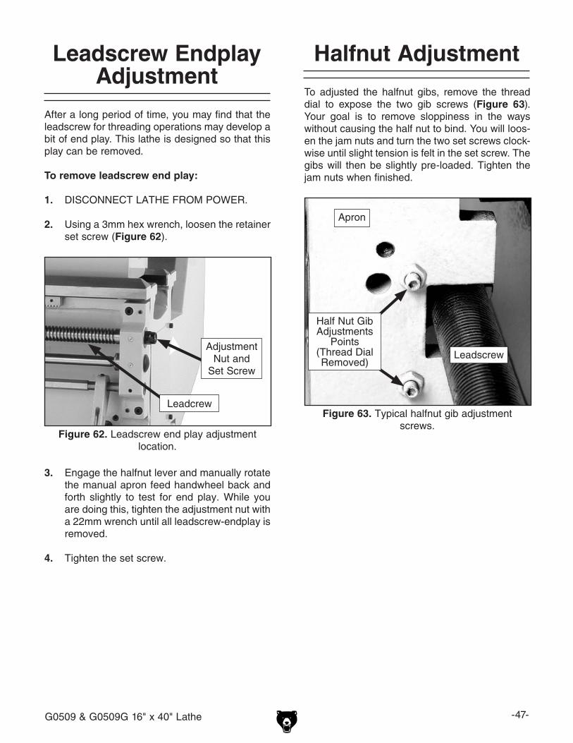
G0509 & G0509G 16" x 40" Lathe -47-
Leadscrew Endplay Adjustment
Halfnut Adjustment
To adjusted the halfnut gibs, remove the thread dial to expose the two gib screws (Figure 63). Your goal is to remove sloppiness in the ways without causing the half nut to bind. You will loos-en the jam nuts and turn the two set screws clock-wise until slight tension is felt in the set screw. The gibs will then be slightly pre-loaded. Tighten the jam nuts when finished.
Figure 63. Typical halfnut gib adjustment screws.
Half Nut Gib Adjustments
Points (Thread Dial Removed)
Leadscrew
Apron
After a long period of time, you may find that the leadscrew for threading operations may develop a bit of end play. This lathe is designed so that this play can be removed.
To remove leadscrew end play:
1. DISCONNECT LATHE FROM POWER.
2. Using a 3mm hex wrench, loosen the retainer set screw (Figure 62).
Figure 62. Leadscrew end play adjustment location.
Adjustment Nut and
Set Screw
Leadcrew
3. Engage the halfnut lever and manually rotate the manual apron feed handwheel back and forth slightly to test for end play. While you are doing this, tighten the adjustment nut with a 22mm wrench until all leadscrew-endplay is removed.
4. Tighten the set screw.
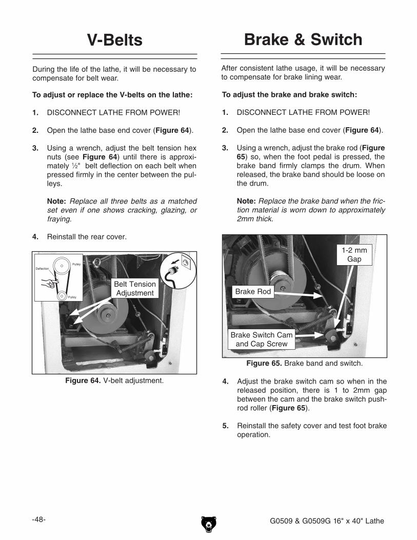
-48- G0509 & G0509G 16" x 40" Lathe
V-Belts
To adjust or replace the V-belts on the lathe:
1. DISCONNECT LATHE FROM POWER!
2. Open the lathe base end cover (Figure 64).
3. Using a wrench, adjust the belt tension hex nuts (see Figure 64) until there is approxi-mately 1⁄2" belt deflection on each belt when pressed firmly in the center between the pul-leys.
Note: Replace all three belts as a matched set even if one shows cracking, glazing, or fraying.
4. Reinstall the rear cover.
Brake & Switch
To adjust the brake and brake switch:
1. DISCONNECT LATHE FROM POWER!
2. Open the lathe base end cover (Figure 64).
3. Using a wrench, adjust the brake rod (Figure 65) so, when the foot pedal is pressed, the brake band firmly clamps the drum. When released, the brake band should be loose on the drum.
Note: Replace the brake band when the fric-
tion material is worn down to approximately 2mm thick.
4. Adjust the brake switch cam so when in the released position, there is 1 to 2mm gap between the cam and the brake switch push-rod roller (Figure 65).
5. Reinstall the safety cover and test foot brake operation.
Figure 65. Brake band and switch.
Brake Rod
1-2 mmGap
Brake Switch Cam and Cap Screw
After consistent lathe usage, it will be necessary to compensate for brake lining wear.
During the life of the lathe, it will be necessary to compensate for belt wear.
Figure 64. V-belt adjustment.
Belt TensionAdjustment
Pulley
Deflection
Pulley

G0509 & G0509G 16" x 40" Lathe -49-
Figure 66. Spanner wrench diagram.
Bearing Preload
This lathe is shipped from the factory with the spindle bearing preload adjusted. If the spindle ever develops a bit of end-play and the workpiece finish suffers, you can adjust the bearing pre-load to remove the end-play and improve the workpiece finish.
Adjusting the bearing preload requires using a spanner wrench or a punch and hammer. You can either purchase the spanner wrench at a tool store or fabricate one, using the diagram shown below in Figure 66.
To adjust the preload:
1. Run the lathe for 20 minutes on high speed to bring the lathe to normal operating temperature.
2. DISCONNECT THE LATHE FROM THE POWER SOURCE!
3. Remove the chuck, shift the spindle to neutral, then remove the lathe end cover to expose the outboard spindle and spanner nut (Figure 67).
Figure 67. Outboard spindle/spanner nut.
Figure 68. Loosening outboard spanner nut.
4. Using a 3mm hex wrench, remove the spanner nut locking set screw (Figure 67).
5. Place the chuck key in the cam-lock socket to keep the spindle from rotating.
6. Using a spanner wrench, or hammer-and-punch, loosen the spanner lock nut (Figure 68) counterclockwise three turns.
Note: You may have to tap on the outboard spindle tube as explained in Step 13 to help unload the spindle and break the spanner nut loose.
Figure 69. Dial indicator setup.
7. Place a dial indicator on the cross slide and move the carriage toward the headstock until the contact point of the indicator touches the spindle face (Figure 69).
Set Screw
Spanner Nut
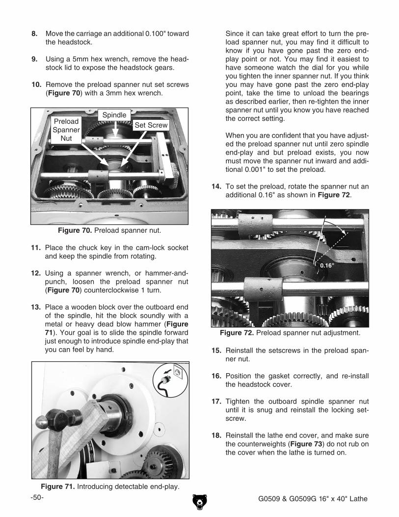
-50- G0509 & G0509G 16" x 40" Lathe
11. Place the chuck key in the cam-lock socket and keep the spindle from rotating.
12. Using a spanner wrench, or hammer-and-punch, loosen the preload spanner nut (Figure 70) counterclockwise 1 turn.
13. Place a wooden block over the outboard end of the spindle, hit the block soundly with a metal or heavy dead blow hammer (Figure 71). Your goal is to slide the spindle forward just enough to introduce spindle end-play that you can feel by hand.
8. Move the carriage an additional 0.100" toward the headstock.
9. Using a 5mm hex wrench, remove the head-stock lid to expose the headstock gears.
10. Remove the preload spanner nut set screws (Figure 70) with a 3mm hex wrench.
Figure 70. Preload spanner nut.
Figure 71. Introducing detectable end-play.
Set ScrewPreload Spanner
Nut
Since it can take great effort to turn the pre-load spanner nut, you may find it difficult to know if you have gone past the zero end-play point or not. You may find it easiest to have someone watch the dial for you while you tighten the inner spanner nut. If you think you may have gone past the zero end-play point, take the time to unload the bearings as described earlier, then re-tighten the inner spanner nut until you know you have reached the correct setting.
When you are confident that you have adjust-ed the preload spanner nut until zero spindle end-play and but preload exists, you now must move the spanner nut inward and addi-tional 0.001" to set the preload.
14. To set the preload, rotate the spanner nut an additional 0.16" as shown in Figure 72.
Figure 72. Preload spanner nut adjustment.
0.16"
15. Reinstall the setscrews in the preload span-ner nut.
16. Position the gasket correctly, and re-install the headstock cover.
17. Tighten the outboard spindle spanner nut until it is snug and reinstall the locking set-screw.
18. Reinstall the lathe end cover, and make sure the counterweights (Figure 73) do not rub on the cover when the lathe is turned on.
Spindle

G0509 & G0509G 16" x 40" Lathe -51-
To confirm that the bearings are correctly pre-loaded:
1. Make sure all safety precautions have been taken and setup steps are complete to make the lathe fully operational.
2. Install the chuck and tighten the jaws.
3. Set the spindle speed to its highest setting.
4. Connect the lathe to power and turn the lathe spindle ON.
5. Let the lathe run for 20 minutes.
6. Turn the spindle OFF, disconnect lathe from power, and check the temperature of the spindle.
—If the spindle nose is hotter than you can comfortably keep your hand on, the pre-load is too tight and you must repeat the bearing preload adjustment procedure.
—If the spindle nose is slightly warm to the touch, you have correct bearing preload. Now complete Spindle Balancing proce-dure.
Spindle Balancing
After the spindle has been broken in, or if the lathe has been used for a considerable amount of time, you should adjust the spindle weights to minimize spindle vibration.
To minimize spindle vibration:
1. Run the lathe for five minutes on the fastest RPM.
2. DISCONNECT LATHE FROM POWER!
3. Open the side cover, loosen the counter weight set screws (Figure 73), and reposition one or both counterweights to a new posi-tion around the circumference of the spanner nut.
Figure 73. Spindle counterweights.
4. Close the side cover, reconnect to power, restart the lathe, and run at 900 RPM.
5. Place your hand on the headstock cover and feel for harmonic vibration.
6. Repeat Steps 2–5 until vibration is reduced to a minimum.
7. Now, repeat Steps 2–5 at 1800 RPM until vibration is reduced to a minimum.
Counterweight
Set Screw
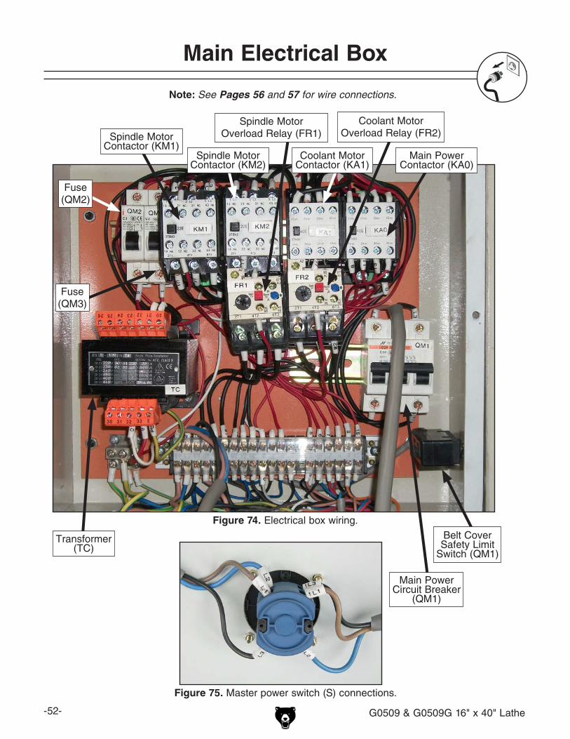
-52- G0509 & G0509G 16" x 40" Lathe
Main Electrical Box
Figure 74. Electrical box wiring.
Spindle MotorContactor (KM1)
Main PowerContactor (KA0)
Main Power Circuit Breaker
(QM1)
Belt Cover Safety Limit
Switch (QM1)
Figure 75. Master power switch (S) connections.
Note: See Pages 56 and 57 for wire connections.
Fuse(QM2)
Fuse(QM3)
Coolant MotorContactor (KA1)
Spindle MotorContactor (KM2)
Transformer (TC)
Coolant MotorOverload Relay (FR2)
Spindle MotorOverload Relay (FR1)
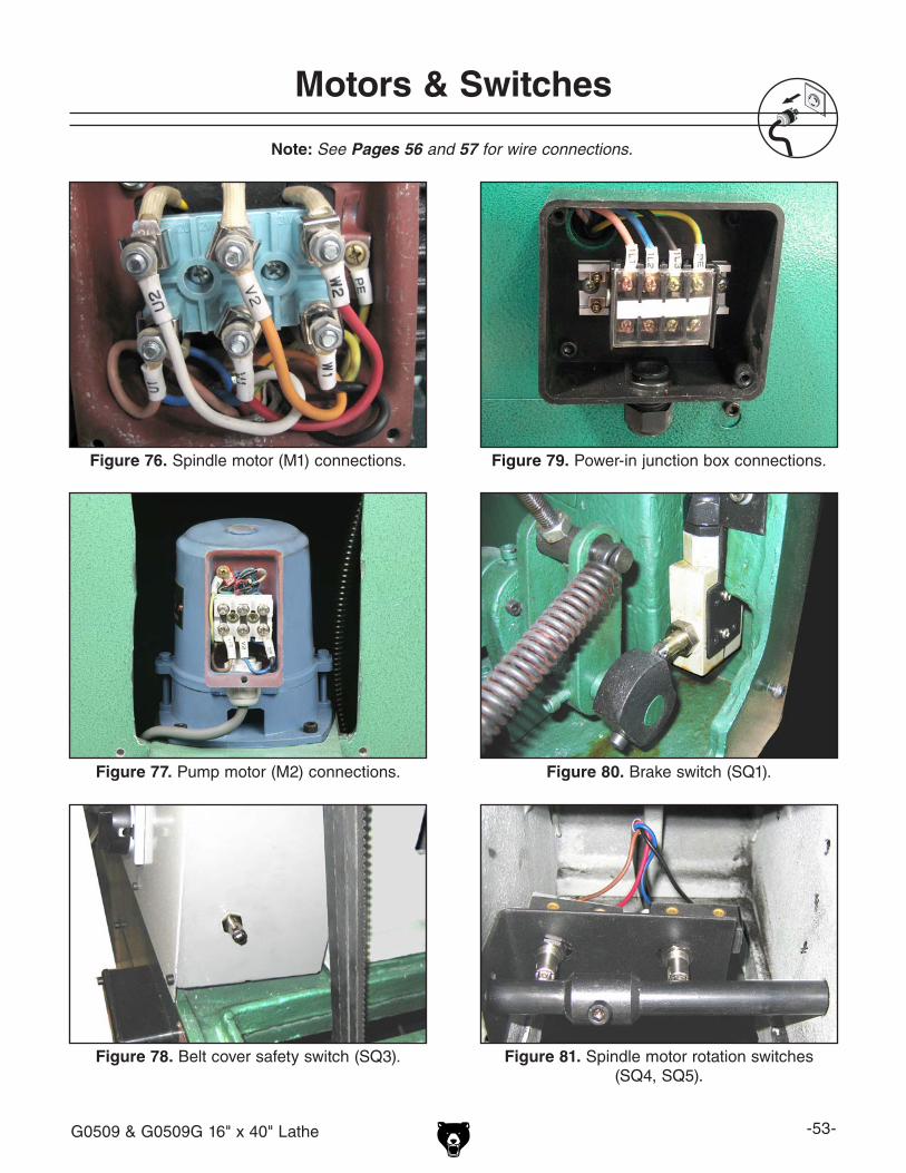
G0509 & G0509G 16" x 40" Lathe -53-
Motors & Switches
Note: See Pages 56 and 57 for wire connections.
Figure 76. Spindle motor (M1) connections.
Figure 77. Pump motor (M2) connections.
Figure 78. Belt cover safety switch (SQ3). Figure 81. Spindle motor rotation switches (SQ4, SQ5).
Figure 80. Brake switch (SQ1).
Figure 79. Power-in junction box connections.

-54- G0509 & G0509G 16" x 40" Lathe
Figure 82. Motor speed switch (SA), side 1. Figure 83. Motor speed switch (SA), side 2.
Figure 85. Work lamp (EL).
Figure 84. Control panel).
Control Panel & Switches
Power Lamp (HL1)
Pump Switch (FR2)
Emergency Stop Switch (SB0)
Jog Button (SB1)
Note: See Pages 56 and 57 for wire connections.
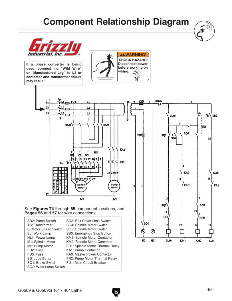
G0509 & G0509G 16" x 40" Lathe -55-
Component Relationship Diagram
If a phase converter is being used, connect the “Wild Wire” or “Manufactured Leg” to L2 or contactor and transformer failure may result!
OFF
SB2: Pump SwitchTC: TransformerS: Motor Speed SwitchEL: Work LampHL1: Power LampM1: Spindle MotorM2: Pump MotorFU2: FuseFU3: FuseSB1: Jog ButtonSQ1: Brake SwitchSQ2: Work Lamp Switch
SQ3: Belt Cover Limit SwitchSQ4: Spindle Motor SwitchSQ5: Spindle Motor SwitchSB0: Emergency Stop ButtonKM1: Spindle Motor ContactorKM2: Spindle Motor ContactorFR1: Spindle Motor Thermal RelayKA1: Pump ContactorKA0: Master Power Contactor FR2: Pump Motor Thermal RelayFU1: Main Circuit Breaker
See Figures 74 through 85 component locations, and Pages 56 and 57 for wire connections.

-56- G0509 & G0509G 16" x 40" Lathe
Main Electrical Box Wiring Diagram
GROUND
PE PE PE
ON
OFF
U1 V1 W1 U21L1
1L1
1L2
1L2
1L3
U1 V1 W1
5 15987610W2W1 V2U2V1U1
V2
BELT COVER SAFETYLIMIT SWITCH
26 2122232425 20
W2
ON
OFF
ON
OFF
L2
0
V1U1
W1
19
14
14
V1 U1
PE
2 3
TOPOWER-IN
JUNCTION BOX
TO MOTOR SPEED
SWITCH
TOPUMP
MOTOR
TOWORKLAMP
TOCONTROL
PANEL
TOBRAKESWITCH
TOSPINDLE
ROTATIONSWITCHES
TOPOWERSWITCH
PE
View this page in color at www.grizzly.com.
TO POWER SWITCH
1L3
33
9
E
PE
32
0
3130
1
1
L1 L2 L3
L2
L1 L3L2
0
1113
0
A1 A1
A1 A1
13NO 21NC 31NC 43NO 13NO 21NC 31NC 43NO 13NO 23NO 33NO 43NO 13NO 23NO 33NO 43NO
14NO 22NC 32NC 44NO 14NO 22NC 32NC 44NO 14NO 24NO 33NO 44NO 14NO 24NO 33NO 44NO
A2 A2
A2 A2
1L1 3L2 5L3
2T1 4T2 6T3 2T1 4T2 6T3
L2
ResetTestH
A
2524 20
16
95NC
A2
NC96
NO98
97NO
2T1 4T2 6T3
U2 V2 W2
ResetTestH
A
10.8
95NC
A2
NO98
97NO
2T1 4T2 6T3
0.70.63
0.9
KM1 ContactorSiemens 3TB43 24V
KM2 ContactorSiemens 3TB43 24V
QM2Fuse
QM3Fuse
KA1 ContactorSiemens 3TH80 24V
OL RelaySiemens JRS2
OL RelaySiemens 3UA5
KA0 ContactorSiemens 3TH80 24V
22E 40E 40E22E
1
TransformerJBK5-120VA TH
TC
L3
L3
FR1 FR2
12
12
L1
L1
L1 L3
L3
L1
L1
L1
L1
2
2 8 976
5 76
15
15
9
0
00
0
Circuit Breaker
QM1
10
10
3 4 5 82 90 76 15L1 L2 L3 U1 V1 W1 U2 V2 W2
17
17
NC96
16
1613118
5
HUILONG DZ451-63 C50
HUILONG HUILONG DZ451-63
C3DZ451-63
C3
Page 57 Page 57 Page 57 Page 57 Page 57 Figure 80
Page 57
Fig
ure 78
Page 57Page 57

G0509 & G0509G 16" x 40" Lathe -57-
Component Wiring Diagram
2 SPEED MOTOR SWITCH
LEFT SIDE
W1 U1
W1 U1
W1
W2
PE
PE
(1)
(2)
(1)
(2)
TO ELECTRICAL
BOX
TO ELECTRICAL
BOX
U1 V1
U2 V2
POWER CORD JUNCTION BOX
TO POWER CORD
TO ELECTRICAL
BOX
PE
PE
1L31L21L1
L1 L2 L3
TO MOTOR
TO MOTOR
PUMP MOTOR
U2 V2 W2
PE
TO ELECTRICAL BOX
MASTER POWER SWITCH, RIGHT SIDE
MASTER POWER SWITCH, LEFT SIDE
TO ELECTRICAL
BOX
TO ELECTRICAL
BOX
L1 L2
L3
5 6 7 8
SPINDLE ROTATION SWITCHES
TO ELECTRICAL BOX
TO ELECTRICAL BOX
TO WORK LAMP
2
2
WORK LAMP WIRING
MOTOR
TO ELECTRICAL BOX
PE
6 5
9
8 9 6
15
PE
TO ELECTRICAL BOX
CONTROL PANEL WIRING
JOG BUTTON
EMERGENCY STOP SWITCH
PUMP SWITCH
POWER LAMP
View this page in color at www.grizzly.com.
V1
0
2 6 10 14
4 8 12 16
13 9 5 1
8
6
5
71
2
15 11 7 3
W1
1L1 1L3
1L2
2 SPEED MOTOR SWITCH
RIGHT SIDE
V1
V2 W2U2
U1
Figure 75
Figure 75
Figure 81
Figure 83
Figure 82
Figure 76
Figure 79
Figure 77
Figure 85
Figure 84
Page 56
Main Wiring Diag 2
Page 56
Page 56 Page 56
Page 56
Page 56
Page 56
Page 56
Page 56
Figure 76
Figure 76
Page 56
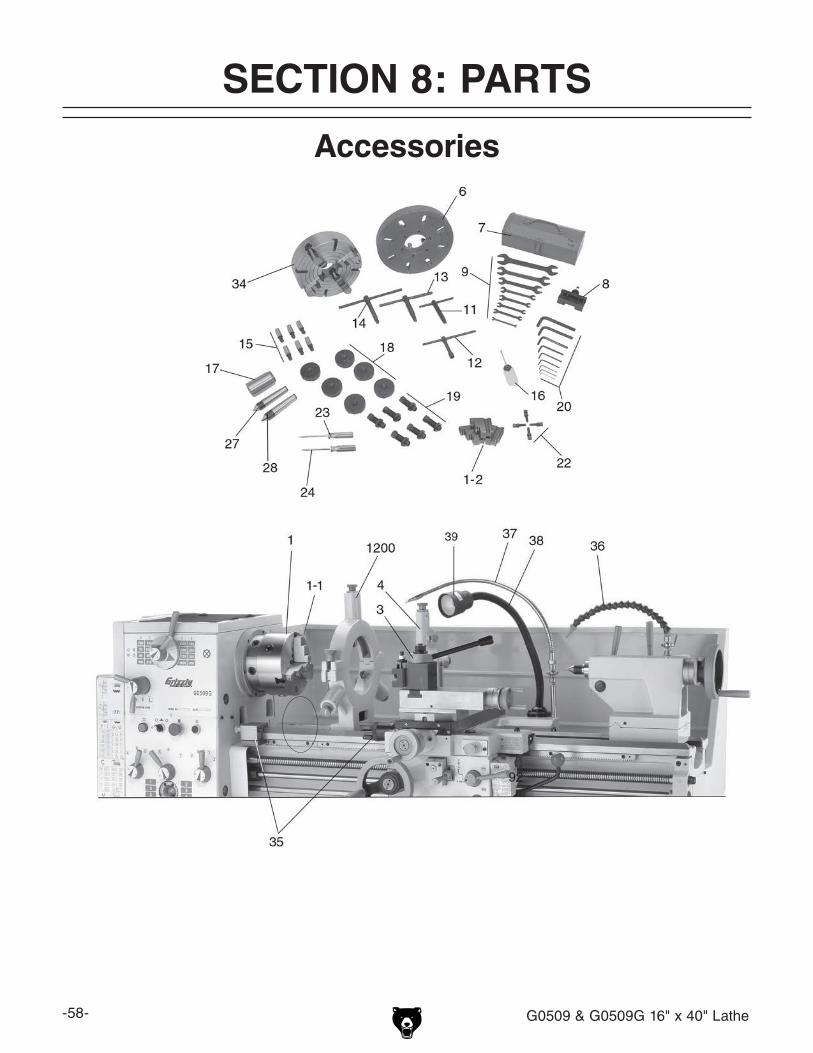
-58- G0509 & G0509G 16" x 40" Lathe
Accessories
SECTION 8: PARTS

G0509 & G0509G 16" x 40" Lathe -59-
Accessories Parts ListREF PART # DESCRIPTION REF PART # DESCRIPTION1 P0509G0001 8" THREE-JAW CHUCK (G0509G) 18 P05090018 CAST-IRON FEET1-1 P0509G0001-1 EXTERNAL JAW SET 3-PC 19 P05090019 JACKING STUDS W/NUTS1-2 P0509G0001-2 INTERNAL JAW SET 3-PC 20 P05090020 HEX WRENCH SET3 P05090003 TOOL POST W/TOOL HOLDER 22 P0509G0022 SPIDER SCREW SET (G0509G)4 P05090004 COMPLETE FOLLOW REST 23 P05090023 #2 PHILLIPS SCREWDRIVER6 P05090006 14" FACEPLATE 24 P05090024 #2 STANDARD SCREWDRIVER7 P05090007 TOOL BOX 27 P05090027 CARBIDE TIP DEAD CENTER MT#48 P05090008 TOOL HOLDER 28 P05090028 STANDARD TIP DEAD CENTER MT#49 P05090009 WRENCH SET 34 P0509034 12" FOUR-JAW UNIVERSAL CHUCK11 P05090011 CAM LOCK T-WRENCH 35 P05090035 MANUAL MICROMITER STOP KIT12 P05090012 TOOL HOLDER T-WRENCH 36 P0509G8009 TAILSTOCK COOLANT KIT (G0509G)13 P05090013 4-JAW CHUCK T-WRENCH 37 P05090037 CUTTING COOLANT HOSE KIT14 P05090014 3-JAW CHUCK T-WRENCH 38 P05090038 WORK LAMP ASSEMBLY15 P05090015 4-JAW CHUCK CAMLOCK STUDS 39 P05090039 LAMP BULB16 P05090016 OIL BOTTLE 1200 P05091200 COMPLETE STEADY REST17 P05090017 MT#6 TO MT#4 ADAPTER

-60- G0509 & G0509G 16" x 40" Lathe
Frame, Ways, & Stand (1-2)
1011
1012
10131014
1015
10161017
1018
10191020
1021
1022
1023
1024
1025
10261026-11026-2
1027
1028
1001
1002
1003
1004
1005
1006
1007
10081009
1010
10971098
1099
11001101
1102
1103

G0509 & G0509G 16" x 40" Lathe -61-
Frame, Ways, & Stand (2-2)
61
104910501051
1052
10551056
1057 1058
1059
1060
1062
1063 1064
10651066
10671068
1069
10701071
1072
1073
1074
1075
1076
79
1029
1030
1042
1043
1044
1045
1046
10771078
1080 1081
1082 10
83
108410851086
1087 1088 1089 1090
1091
1092
1093
1094
1095
1096
1031
1032
1033

-62- G0509 & G0509G 16" x 40" Lathe
REF PART # DESCRIPTION REF PART # DESCRIPTION61 P0509061 TAPER PIN 8 X 85MM 1055 PSB92M CAP SCREW M12-1.75 X 4079 P0509079 RACK 1056 P05091056 DOWEL PIN 12 X 30MM1001 PS68M PHLP HD SCR M6-1 X 10 1057 P05091057 COVER1002 P05091002 COVER (G0509) 1058 P05091058 GUARD ASSEMBLY
P0509G1002 COVER (G0509G) 1059 P05091059 GAP BLOCK1003 P05091003 STAND 1060 PSB70M CAP SCREW M10-1.5 X 451004 P05091004 PULLEY 1062 PN03M HEX NUT M8-1.251005 P05091005 BELT BRAKE 1063 PSB05M CAP SCREW M8-1.25 X 501006 PS68M PHLP HD SCR M6-1 X 10 1064 P05091064 RACK1007 PS68M PHLP HD SCR M6-1 X 10 1065 P05091065 CLUTCH1008 P05091008 SWITCH SEAT 1066 P05091066 STEEL BALL 8MM1009 PN04M HEX NUT M4-.7 1067 P05091067 TAPER PIN 5 X 45MM1010 PSB21M CAP SCREW M4-.7 X 30 1068 P05091068 COMPRESSION SPRING 1.2 X 6 X 46MM1011 P05091011 LIMIT SWITCH 1069 P05091069 SPECIAL SCR M10-1.5 X 101012 P05091012 MOTOR SEAT BRACKET 1070 P05091070 SLEEVE1013 P05091013 SHAFT 1071 P05091071 DOWEL PIN1014 P05091014 CAM 1072 P05091072 THRUST WASHER1015 P05091015 BRAKE ARM 1073 PR19M EXT RETAINING RING 28MM1016 P05091016 SHAFT 1074 PK08M KEY 5 X 5 X 16MM1017 P05091017 SPRING 1075 P05091075 COMPRESSION SPRING 1.8 X 2.5 X 551018 P05091018 SHAFT 1076 P05091076 COVER1019 P05091019 MOTOR SEAT 1077 PSB07M CAP SCREW M6-1 X 301020 PB31M HEX BOLT M10-1.5 X 40 1078 PRP08M ROLL PIN 6 X 30MM1021 PLW06M LOCK WASHER 10MM 1080 P05091080 ROD1022 PLW10M LOCK WASHER 16MM 1081 P05091081 FEED ROD1023 PN13M HEX NUT M16-2 1082 P05091082 LEAD SCREW1024 P05091024 THREADED STUD M16-2 X 150 1083 P05091083 SLEEVE1025 P05091025 SPECIAL WASHER 1084 PSS02M SET SCREW M6-1 X 61026 P05091026 MOTOR 1085 PSB40M CAP SCREW M8-1.25 X 351026-1 P05091026-1 MOTOR FAN COVER 1086 P05091086 SLEEVE1026-2 P05091026-2 MOTOR FAN 1087 P05091087 TAPER PIN 6 X 50MM1027 P05091027 COVER (G0509) 1088 P8203 THRUST BEARING 8203
P0509G1027 COVER (G0509G) 1089 P05091089 SLEEVE1028 PSB04M CAP SCREW M6-1 X 10 1090 PSS03M SET SCREW M6-1 X 81029 P05091029 COVER 1091 P05091091 PLUG1030 P05091030 SLEEVE 1092 P05091092 END PLAY ADJUSTMENT NUT1031 P05091031 BRACKET 1093 P05091093 STEEL BALL 9.5MM1032 P05091032 ARM 1094 P05091094 COMPRESSION SPRING 1 X 9 X 20MM1033 P05091033 BRAKE PEDAL 1095 PSB68M CAP SCREW M6-1 X 81042 PSB52M CAP SCREW M8-1.25 X 10 1096 P05091096 BRACKET1043 P05091043 CLEVIS PIN 7.5 X 25MM 1097 P05091097 STUD M12-1.75 X 1001044 PEC09M E-CLIP 6MM 1098 PN09M HEX NUT M12-1.751045 P05091045 ROD 1099 PW06M FLAT WASHER 12MM1046 P05091046 LEVER 1100 P05091100 BED1049 P05091049 KNURLED THUMB NUT 1101 PB24M HEX BOLT M12-1.75 X 451050 P05091050 MOUNTING STUD 1102 PLW05M LOCK WASHER 12MM1051 PN02M HEX NUT M10-1.5 1103 P0509G1103 BUFFER BUMPER1052 PB35M HEX BOLT M12-1.75 X 40
Frame, Ways, & Stand Parts List
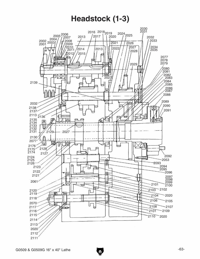
G0509 & G0509G 16" x 40" Lathe -63-
Headstock (1-3)
20012002 2003
2004200520062007
20082009201020112012
2013
20142015
20162017
201820192020
2021
2022
2023
20242025
202620272028
2029
20302031
20322033
20342035
207720782079
20802081208220832084208520862087
2088
208920902091
2013
20532092
209320942095
209620972098209921002101
21022103
2104
21052106
2107
2020
210821092101
2110 2020
2138
2139
2032
2077
2061
2070
21132020
2027
2111
2112
2113
2114
211521162117
211821192120
212121222123
212421252126
2127
2128
2129
2130
21312132213321342135
2136
2137
217621752174
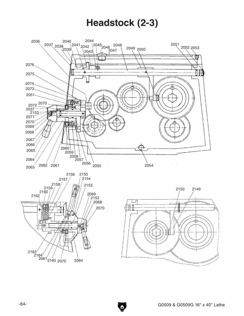
-64- G0509 & G0509G 16" x 40" Lathe
Headstock (2-3)
2068
20362037 2038
2039
204020412042
2043
20442045
20462047
20482049 2050
20512052
205420552056
20572058
20592060
206120622063
2064
20662067
2068
2069
2070
2071
2072
20732074
2075
2076
2152
2153
215421552156
21572158
21592160
2162
21632164
2165
2053
2051
2037
2070
2065
2153
2069
2070
20612070 2064
21492150
2068

G0509 & G0509G 16" x 40" Lathe -65-
Headstock (3-3)
214021412142
21432144
21452146
21472148 21512161
21662167
20652066
214121702171
2172
2173
21682169
(G0509)
(G0509G)
(G0509G)

-66- G0509 & G0509G 16" x 40" Lathe
Parts List
REF PART # DESCRIPTION REF PART # DESCRIPTION2001 P05092001 HEX NUT M30-1.5 2048 P05092048 SHAFT2002 P05092002 TOOTHED LOCK WASHER 30MM 2049 P05092049 LEVER2003 PK41M KEY 8 X 8 X 40MM 2050 P05092050 FORK2004 P05092004 SHAFT 2051 P05092051 O-RING 14 X 2.65MM2005 P05092005 PULLEY 2052 P05092052 PLUG2006 P05092006 SPACER 2053 PSB07M CAP SCREW M6-1 X 302007 P05092007 OIL SEAL 2054 P05092054 OIL PLUG2008 P05092008 O-RING 36 X 3.5MM 2055 P05092055 FORK2009 P05092009 BEARING COVER 2056 P05092056 LEVER2010 P05092010 PACKING 2057 P05092057 STEEL BALL 10MM2011 PSB29M CAP SCREW M6-1 X 40 2058 P05092058 COMPRESSION SPRING 0.9 X 9 X 35MM2012 P6206ZZ BALL BEARING 6206 2059 P05092059 BRACKET2013 P05092013 KEY 8 X 8 X 50MM 2060 PSS01M SET SCREW M6-1 X 102014 P05092014 GEAR 38-TOOTH 2061 P05092061 O-RING 28 X 3.1MM2015 P05092015 GEAR 33-TOOTH 2062 P05092062 COVER2016 P05092016 SLEEVE 2063 P05092063 LEVER HUB2017 P05092017 GEAR 23-TOOTH 2064 P05092064 O-RING 10 X 2.65MM2018 P05092018 GEAR 33-TOOTH 2066 P05092066 LEVER2019 P6205ZZ BALL BEARING 6205ZZ 2067 P05092067 LEVER HUB2020 PR11M EXT RETAINING RING 25MM 2068 PR04M EXT RETAINING RING 6MM2021 PSS34M SET SCREW M5-.8 X 16 2069 PK05M KEY 4 X 4 X 10MM2022 P05092022 PLUG 2070 PSB26M CAP SCREW M6-1 X 122023 P05092023 BALL BEARING E206 (G0509) 2071 P05092071 PLATE2024 PR15M EXT RETAINING RING 30MM 2072 P05092072 SHAFT2025 P05092025 SHAFT 2073 P05092073 COMPRESSION SPRING 0.9 X 9 X 40MM2026 PR56M EXT RETAINING RING 45MM 2074 P05092074 LEVER2027 PK136M KEY 8 X 8 X 30MM 2075 P05092075 BRACKET2028 P05092028 GEAR 60-TOOTH 2076 P05092076 FORK2029 P05092029 GEAR 21-TOOTH 2077 PSS03M SET SCREW M6-1 X 82030 P05092030 PLUG 2078 P05092078 SPANNER NUT2031 P05092031 O-RING 19 X 2.65MM 2079 P05092079 LEAD PLUG2032 P6305ZZ BALL BEARING 6305ZZ 2080 P05092080 TAPERED ROLLER BEARING 2033 P05092033 EXT RETAINING RING 62MM 2081 P05092081 EXT RETAINING RING 75MM2034 P05092034 COVER 2082 P05092082 GEAR 43-TOOTH 2035 P05092035 O-RING 56 X 3.5MM 2083 P05092083 GEAR 82-TOOTH 2036 P05092036 PLATE 2084 P05092084 KEY 8 X 8 X 60MM2037 P05092037 FLAT HD SCR M3-.5 X 15 2085 P05092085 TAPERED ROLLER BEARING 2038 P05092038 PACKING 2086 P05092086 COVER2039 P05092039 COVER 2087 P05092087 PACKING2040 P05092040 CASTING 2088 P05092088 CAM LOCK2041 PRP05M ROLL PIN 5 X 30MM 2089 P05092089 COMPRESSION SPRING2042 P05092042 GEAR 43-TOOTH 2090 P05092090 SPECIAL CAP SCREW2043 P05092043 BRACKET 2091 P05092091 SPINDLE D1-6 (G0509)2044 P05092044 SLEEVE P0509G2091 SPINDLE D1-6 (G0509G)2045 PSS01M SET SCREW M6-1 X 10 2092 P05092092 CAM LOCK STUD2046 P05092046 PLUG 2093 P05092093 SHAFT2047 P05092047 COVER 2094 P05092094 SPACER
Headstock Parts List

G0509 & G0509G 16" x 40" Lathe -67-
REF PART # DESCRIPTION REF PART # DESCRIPTION2095 PR10M EXT RETAINING RING 22MM 2137 P05092137 COVER2096 P05092096 GEAR 36-TOOTH 2138 P05092138 SPACER2097 P05092097 GEAR 24-TOOTH 2139 P05092139 SPACER2098 P05092098 GEAR 48-TOOTH 2140 P05092140 PLATE2099 PK34M KEY 5 X 5 X 20MM 2141 P05092141 COVER (G0509)2100 PR62M EXT RETAINING RING 42MM P0509G2141 COVER (G0509G)2101 P6204-2RS BALL BEARING 6204 2142 PS79M PHLP HD SCR M3-.5 X 82102 P05092102 SHAFT 2143 P05092143 KNURLED NUT M10-1.52103 P05092103 KEY 8 X 8 X 115MM 2144 P05092144 STUD M10-1.5 X 852104 P05092104 GEAR 26-TOOTH 2145 PN02M HEX NUT M10-1.52105 P05092105 SLEEVE 2146 P05092146 LEVER W/HUB ASSEMBLY2106 P05092106 GEAR 24-TOOTH 2147 P05092147 SPECIAL SCR M12-1.75 X 202107 P05092107 GEAR 48-TOOTH 2148 P05092148 BRACKET2108 P05092108 SHAFT 2149 P05092149 BRACKET2109 PR09M EXT RETAINING RING 20MM 2150 P05092150 FORK2110 P05092110 GEAR 36-TOOTH 2151 P05092151 SIGHT GLASS 16MM2111 P05092111 PACKING 2152 P05092152 LEVER BRACKET2112 P60052RS BALL BEARING 6005 2153 PK14M KEY 5 X 5 X 18MM2113 PSB27M CAP SCREW M6-1 X 14 2154 P05092154 RIVET 2 X 5MM2114 P05092114 COVER 2155 P05092155 PLATE2115 P05092115 OIL SEAL 2156 P05092156 STEEL BALL 6.5MM2116 P05092116 CHANGE GEAR 24-TOOTH 2157 P05092157 COMPRESSION SPRING 1 X 5 X 22MM2117 P05092117 SPACER 2158 PSS14M SET SCREW M8-1.25 X 122118 P05092118 O-RING 46 X 3.5MM 2159 P05092159 LEVER SHAFT2119 P05092119 COVER 2160 P05092160 DOWEL PIN2120 P6204-2RS BALL BEARING 6204 2161 P05092161 LEVER2121 P05092121 GEAR 48-TOOTH 2162 P05092162 BRACKET2122 P05092122 SLEEVE 2163 P05092163 GEAR SHAFT 37-TOOTH2123 P05092123 BALL BEARING E213 2164 P05092164 LEVER BRACKET2124 P05092124 COVER 2165 P05092165 COVER2125 P05092125 PACKING 2166 PK101M KEY 6 X 6 X 14MM2126 PSB06M CAP SCREW M6-1 X 25 2167 P05092167 SPECIAL ADJUSTING SCREW2127 P05092127 OIL RING 2168 PSB143M CAP SCREW M10-1.5 X 50 (G0509G)2128 PSS01M SET SCREW M6-1 X 10 2169 PW04M FLAT WASHER 10MM (G0509G)2129 P05092129 SPANNER NUT 2170 P0509G2170 HINGE (G0509G)2130 P05092130 COUNTERWEIGHT 2171 PSB110M CAP SCREW M4-.7 X 6 (G0509G)2131 P05092131 GEAR 39-TOOTH 2172 P0509G2172 COVER (G0509G)2132 P05092132 GEAR 54-TOOTH 2173 PSB31M CAP SCREW M8-1.25 X 25 (G0509G)2133 P05092133 GEAR 47-TOOTH 2174 P0509G2174 SPIDER BOLT 3/8-18 X 1-1/2" (G0509G)2134 P05092134 GEAR 31-TOOTH 2175 P0509G2175 SPIDER BOLT 3/8-24 X 1/2" (G0509G)2135 PR13M EXT RETAINING RING 65MM 2176 PN11 HEX NUT 3/8-24 (G0509G)2136 P05092136 PACKING
Headstock Parts List

-68- G0509 & G0509G 16" x 40" Lathe
Gearbox (1-3)
3001
3002
3003
3004
3005
3006
3007
3008
3009
3010
3011
3012
3013
3014
3015
3017
3018 3019
3020
3021 30
22
3023
302430
25 3026 3027
3028
3029 30
303031 303230
33 3034
3035 3036
3037 3038 3039 3040 3041
3042 30
433044
3045 30
46 3047
3098
309931
00 310131
02 310331
0431053106 3107
3108
3109
3110
3111
3112
3113 31
143115 3116 3117311831
19 3120 31
21 3122
312331243125
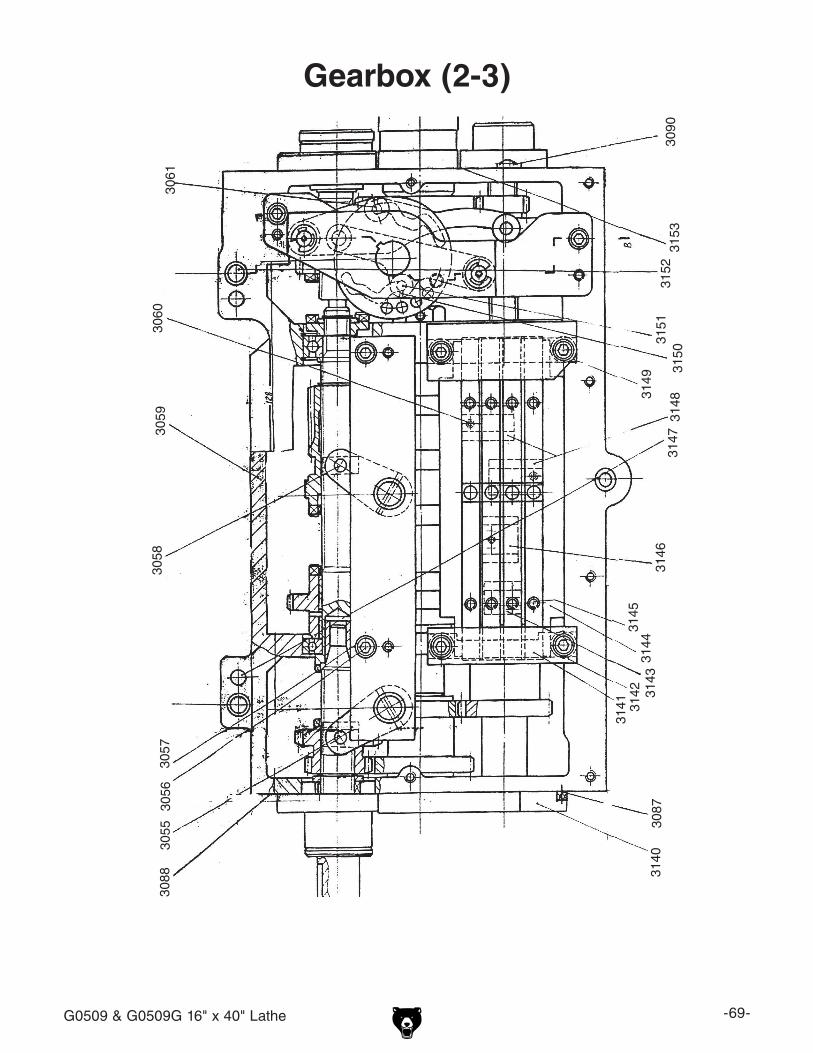
G0509 & G0509G 16" x 40" Lathe -69-
Gearbox (2-3)
3140
3141 3142 3143
3144
3145
3146
3147
3148
3149
31503151
3152
3153
3055
3056
3057
3058
3059
3060
3061
3087
3088
3090

-70- G0509 & G0509G 16" x 40" Lathe
Gearbox (3-3)
3062
3063
3064
3065
3067
3068
3069
3070
3071
3072
3073
3074
3075
3076
3077
3078
3079
3080
3081
3082
3083
3084
3085
3086
3089
3094
3097
44830
493050305130
523053
3120 3127 3128 3129 31
30
3131
313231
33
3054
3091
3095
3096
3034
3035
3036
30373038
3039
3155 3156 3157 3158
3159

G0509 & G0509G 16" x 40" Lathe -71-
Parts List
Gearbox Parts ListREF PART # DESCRIPTION REF PART # DESCRIPTION448 P05090448 LEVER 3054 P05093054 FORK3001 PEC06M E-CLIP 20MM 3055 P05093055 FORK3002 P05093002 ROLLER BEARING 943/20 3056 PSB01M CAP SCREW M6-1 X 163003 P05093003 OIL SEAL 3057 PLW03M LOCK WASHER 6MM3004 P05093004 SHAFT 3058 P05093058 FORK3005 PSB11M CAP SCREW M8-1.25 X 16 3059 P05093059 CASTING3006 P05093006 WIDE WASHER 3060 PSB15M CAP SCREW M5-.8 X 203007 P05093007 KEY 8 X 8 X 28MM 3061 P05093061 FORK3008 P05093008 SLEEVE 3062 P05093062 LEVER3009 P05093009 CHANGE GEAR 57-TOOTH 3063 P05093063 COMPRESSION SPRING 1 X 8 X 323010 P05093010 SHAFT 3064 P05093064 LEVER3011 PN32M HEX NUT M14-2 3065 P05093065 SELECTOR3012 P05093012 SLEEVE 3067 P05093067 COVER3013 P05093013 WIDE WASHER 14MM 3068 P05093068 O-RING 30 X 2.65MM3014 P05093014 ROLLER BEARING 160105 3069 P05093069 COVER3015 PR25M INT RETAINING RING 47MM 3070 PSB38M CAP SCREW M5-.8 X 253017 P05093017 CHANGE GEAR 44/52-TOOTH 3071 P05093071 BRACKET3018 P05093018 BELLCRANK SWING ARM 3072 P05093072 O-RING 38.7 X 2.65MM3019 PSB01M CAP SCREW M6-1 X 16 3073 PSB01M CAP SCREW M6-1 X 163020 P05093020 BRACKET 3074 P05093074 BRACKET3021 P05093021 THRUST WASHER 3075 PSS02M SET SCREW M6-1 X 63022 P05093022 GEAR 39/20-TOOTH 3076 P05093076 CAP SCREW3023 P05093023 BALL BEARING 7000104 3077 P05093077 STEEL BALL 6MM3024 P05093024 SHAFT 3078 P05093078 FORK3025 P05093025 GEAR 38-TOOTH 3079 P05093079 FORK3026 P05093026 GEAR 22-TOOTH 3080 P05093080 FORK3027 P05093027 GEAR 19-TOOTH 3081 P05093081 FORK3028 P05093028 GEAR 20-TOOTH 3082 P05093082 DRIVE PLATE3029 P05093029 GEAR 24-TOOTH 3083 P05093083 COMPRESSION SPRING .8 X 5 X 173030 P05093030 GEAR 23-TOOTH 3084 P05093084 TOP PLATE3031 P05093031 GEAR 27-TOOTH 3085 P05093085 SLEEVE3032 P05093032 GEAR 23/19-TOOTH 3086 PSB48M CAP SCREW M6-1 X 353033 P05093033 GEAR 24-TOOTH 3087 P05093087 PLUG3034 P05093034 GEAR 28-TOOTH 3088 P05093088 OIL INLET PIPE3035 P05093035 GEAR 26-TOOTH 3089 PSB127M CAP SCREW M6-1 X 653036 P05093036 GEAR 38-TOOTH 3090 P05093090 SIGHT GLASS 20MM3037 P05093037 THRUST WASHER 3091 PS05M PHLP HD SCR M5-.8 X 83038 P203 BALL BEARING 203 3094 P05093094 PLATE3039 PR23M INT RETAINING RING 40MM 3095 P05093095 PLATE3040 P05093040 CLUTCH 3096 P05093096 LEVER3041 PR02M EXT RETAINING RING 14MM 3097 PSB42M CAP SCREW M6-1 X 853042 P05093042 CLUTCH GEAR 3098 P05093098 PACKING3043 P05093043 SHAFT 3099 P05093099 PACKING3044 P05093044 THRUST WASHER 3100 P05093100 THRUST WASHER3045 P05093045 PACKING 3101 P05093101 SHAFT3046 P05093046 COVER 3102 P05093102 GEAR 30/19-TOOTH3047 P05093047 THRUST WASHER 3103 P05093103 THRUST WASHER3049 PR18M EXT RETAINING RING 17MM 3104 PK08M KEY 5 X 5 X 16MM3050 P05093050 KEY 3 X 3 X 12MM 3105 P05093105 GEAR 22-TOOTH3051 P05093051 CAM 3106 P05093106 SHAFT3052 P05093052 BRACKET 3107 PR11M EXT RETAINING RING 25MM3053 P05093053 SHAFT

-72- G0509 & G0509G 16" x 40" Lathe
Gearbox Parts ListREF PART # DESCRIPTION REF PART # DESCRIPTION3108 P05093108 GEAR 22-TOOTH 3134 PRP56M ROLL PIN 4 X 25mm3109 P05093109 GEAR 22-TOOTH 3135 P05093135 PACKING3110 P05093110 GEAR 33-TOOTH 3136 P05093136 LEVER3111 P05093111 GEAR 22-TOOTH 3137 P05093083 COMPRESSION SPRING 3112 P05093112 THRUST WASHER 3138 P05093138 SELECTOR BAR3113 P05093113 SPECIAL NUT 3139 P05093139 SHAFT3114 PSS07M SET SCREW M5-.8 X 5 3140 P05093140 COVER3115 P05093115 SHAFT 3141 P05093141 PLATE3116 PR10M EXT RETAINING RING 22MM 3142 P05093142 PLATE3117 PK15M KEY 5 X 5 X 35MM 3143 P05093143 FORK3118 P05093118 GEAR 33-TOOTH 3144 PRP70M ROLL PIN 5 X 18MM3119 P05093119 GEAR 36/20-TOOTH 3145 PRP44M ROLL PIN 3 X 10MM3120 P05093120 ROLLER BEARING 101 3146 P05093146 FORK3121 PR03M EXT RETAINING RING 12MM 3147 P05093147 TAPER PIN 8 X 90MM3122 P05093122 BRACKET 3148 P05093148 FORK3123 P05093123 OIL SEAL 3149 P05093149 PLATE3124 P8105 THRUST BEARING 8105 3150 PRP37M ROLL PIN 3 X 14MM3125 P05093125 BRACKET 3151 P05093151 FORK3126 P05093126 THRUST WASHER 3152 PSB35M CAP SCREW M8-1.25 X 603127 PSS20M SET SCREW M8-1.25 X 8 3153 P05093153 PACKING3128 PR39M EXT RETAINING RING 8MM 3154 PS07M PHLP HD SCR M4-.7 X 83129 P05093083 COMPRESSION SPRING 3155 PSB33M CAP SCREW M5-.8 X 123130 P05092156 STEEL BALL 6.5MM 3156 P05093156 WASHER3131 P05093131 LEVER 3157 P05093157 SLEEVE3132 P05093132 LEVER 3158 P05093158 O-RING 16 X 2.65MM3133 P05093133 FORK 3159 P05093159 LEVER

G0509 & G0509G 16" x 40" Lathe -73-
Apron (1-2)
619
631
4001
4002
4003
4006
4007
4008
4009
4010
4011
401240
1340144015
4016
40174018
40204021
4022 40
23
4024
402540264027
4028 40
29 4030
40324033 4034 4035 40
36
4037
40384039
4040
4041
40434044
4045404640
474048
4049
4050
4051
4052
4053
4054
4062
4067
4068
4069
4074
4075
4076
4077
4078
40794080
4081
4082
4083
4086
4088
4089
4090
4091
4102
4105
4060
4105
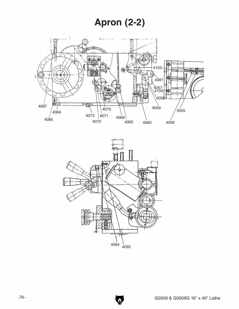
-74- G0509 & G0509G 16" x 40" Lathe
Apron (2-2)
4055
4056
4057
4058
4059
4060
4061
4064
40654066
4070
4071
4072
40734084
4085
4087
4092
4103
4104

G0509 & G0509G 16" x 40" Lathe -75-
Apron Parts ListREF PART # DESCRIPTION REF PART # DESCRIPTION619 P05090619 SHAFT 4051 P05094051 BEVEL-DRIVE GEAR 23-TOOTH 631 P05090631 SHAFT 4052 PSB24M CAP SCREW M5-.8 X 164001 P05094001 APRON CASTING 4053 P05094053 GIB4002 P05094002 SHAFT 4054 PSS26M SET SCREW M5-.8 X 64003 PSB38M CAP SCREW M5-.8 X 25 4055 P05094055 CAP SCREW4006 P05094006 NAME PLATE 4056 P05094056 LEVER4007 P05094007 SLEEVE 4057 P05094057 WORM GEAR BRACKET4008 P05094008 HANDLE 4058 P05094058 SPINDLE CONTROL LEVER4009 P05094009 CAP SCREW 4059 P05094059 DOWEL PIN 8 X 60MM4010 P05094010 HAND WHEEL 4060 PSB01M CAP SCREW M6-1 X 164011 P05094011 DIAL 4061 P05094061 GEAR 18/60-TOOTH4012 P05092156 STEEL BALL 6.5MM 4062 P05094062 KEY4013 P05094013 COMPRESSION SPRING 4064 P05094064 BALL OILER 8MM4014 P05094014 SCREW PLUG 4065 P05094065 VALVE4015 PSS24M SET SCREW M5-.8 X 25 4066 P05093090 SIGHT GLASS 20MM4016 P05094016 WOODRUFF KEY 5 X 6.5 X 16MM 4067 P05094067 CASTING4017 P05094017 GEAR 81-TOOTH 4068 P05094068 HALF BRACKET4018 PSB04M CAP SCREW M6-1 X 10 4069 P05094069 STOP4020 PK147M KEY 6 X 6 X 18MM 4070 P05094070 GEAR SHAFT 14-TOOTH 4021 P05094021 GEAR 80/60-TOOTH 4071 PSS02M SET SCREW M6-1 X 64022 P05094022 GEAR 72/60-TOOTH 4072 PSB78M CAP SCREW M5-.8 X 404023 P05094023 DOWEL PIN 4 X 20mm 4073 P05094073 PLUG4024 P05094024 SHAFT 4074 P05094074 FORK4025 P05094025 LEVER HUB 4075 PRP73M ROLL PIN 4 X 30MM4026 P05094026 SLEEVE 4076 P05094076 PACKING4027 P05094027 LEVER 4077 PSB17M CAP SCREW M4-.7 X 104028 PRP88M ROLL PIN 5 X 22MM 4078 P05094078 COVER4029 P05094029 GEAR 18-TOOTH 4079 P05094079 SHAFT4030 P05094030 O-RING 11.2 X 2.65MM 4080 P05094080 BEVEL-DRIVE GEAR 64-TOOTH 4032 PRP88M ROLL PIN 5 X 22MM 4081 P05094081 THRUST WASHER4033 P05094033 SHAFT 4082 P05094082 GEAR 18-TOOTH4034 PR06M EXT RETAINING RING 16MM 4083 PK10M KEY 5 X 5 X 12MM4035 P05094035 INDICATOR PLATE 4084 P05094084 BOTTOM PLATE4036 P05094036 RIVET 2 X 6MM 4085 P05094085 PACKING4037 P05094037 SHAFT 4086 P05094086 O-RING 17 X 2.65MM4038 P05094038 O-RING 25.8 X 3.55MM 4087 PSB35M CAP SCREW M8-1.25 X 604039 P05094039 SLEEVE 4088 P05094088 GEAR 18-TOOTH4040 P05094040 O-RING 16 X 1.8MM 4089 P8106 THRUST BEARING 81064041 P05094041 PLUG 4090 P05094090 NEEDLE BEARING4043 PEC015M E-CLIP 8MM 4091 PR15M EXT RETAINING RING 30MM4044 PSB52M CAP SCREW M8-1.25 X 10 4092 PS38M PHLP HD SCR M4-.7 X 104045 PRP29M ROLL PIN 5 X 45MM 4102 P05094102 HALF NUT4046 P05094046 SHAFT 4103 PB02M HEX BOLT M6-1 X 124047 P05094047 LEVER HUB 4104 PB04M HEX BOLT M6-1 X 104048 P05094048 HANDLE 4105 P05094105 INPUT BUSHING4049 P05094030 O-RING 11.2 X 2.65MM 4106 PFH06M FLAT HD SCR M6-1 X 204050 P05094050 THRUST WASHER

-76- G0509 & G0509G 16" x 40" Lathe
Cross Slide, Compound Rest, Oil Pump
828
832
867873878
5001
5002
5003
5004
5005
500650075008500950105011
5012
5013
5014
50155016501750185019
5020
5021
502250235024
50255026
5029
5030
5031
5033
5034
5035
5036
5037
503850395040
50415042504350445045
5046
5048 5049
5050
5051505250535054
505550565057
50585059
5060
50615062
506350655066
5068507050715072
50745079
5080
5081 50825083 5084
50855086
50875088 5090
5091
5092
5095
5096
50695020
5014
50075019
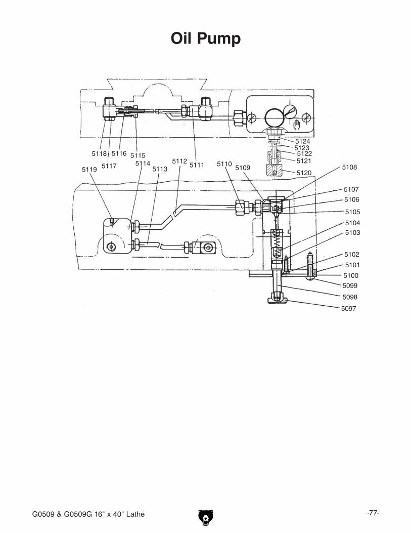
G0509 & G0509G 16" x 40" Lathe -77-
Oil Pump
5097
5098
5099
5100
5101
5102
51035104
5105
5106
5107
510851095110511151125113
511451155116
5117
5118
5119 5120
5121512251235124

-78- G0509 & G0509G 16" x 40" Lathe
REF PART # DESCRIPTION REF PART # DESCRIPTION828 P05090828 GIB 5050 P05095050 BALL OILER 8MM832 P05090832 COVER-CROSS SLIDING 5051 P05095051 BRACKET867 P05090867 GIB 5052 P05095052 CAP SCREW M4-.7 X 10873 P05090873 HALF NUT 5053 P05095053 CLAMP SCREW878 P05090878 FEED SCREW 5054 P05095054 PHLP HD SCR M6-1 X 355001 P05095001 PUMP BODY 5055 P05095055 WHEEL5002 P05095002 CLAMP BLOCK 5056 P05095056 HANDLE SPACER5003 P05095003 SUPPORT SCREW 5057 P05095057 SHOULDER SCREW5004 P05095004 CLAMP SCREW 5058 P05095058 FEED DIAL5005 P05095005 HANDLE 5059 P05095059 HANDLE SPACER5006 P05095006 HANDLE 5060 P05095060 THRUST WASHER5007 P05095007 CAP SCREW M6-1 X 8 5061 P05095061 WIPER COVER5008 P05095008 FEED SCREW 5062 P05095062 WIPER5009 P05095009 PLUG 5063 P05095063 HEX NUT M10-1.55010 P05095010 KEY 4 X 4 X 12MM 5065 P05095065 SET SCREW M8-1.25 X 85011 P05095011 HANDLE 5066 P05095066 BASE5012 P05095012 DIAL-COMPOUND REST 5068 P05095068 GIB SCREW5013 P05095013 STEEL BALL 5069 P05095069 SLEEVE5014 P05095014 COMPRESSION SPRING 0.5 X 5 X 18 5070 P05095070 BUSHING5015 P05095015 STEEL BALL 6MM 5071 P05095071 DETENT PIN5016 P05095016 SEAT 5072 P05095072 SET SCREW M6-1 X 205017 P05095017 THRUST BEARING 8101 5074 P05095074 BRACKET5018 P05095018 PLUG 5079 P05095079 BRACKET5019 P05095019 GIB 5080 P05095080 SPACER5020 P05095020 SET SCREW M6-1 X 10 5081 P05095081 GIB5021 P05095021 BLOCK NUT 5082 P05095082 GIB5022 P05095022 TOOL POST SHAFT 5083 P05095083 GIB5023 P05095023 CLAMPING HANDLE 5084 P05095084 CAP SCREW M6-1 X 205024 P05095024 RUB WASHER 5085 P05095085 THRUST WASHER5025 P05095025 TOOL POST ASSEMBLY 5086 P05095086 GEAR 25-TOOTH5026 P05095026 TOOLING SCREW M10-1.5 X 50 5087 P05095087 CAP SCREW M5-.8 X 105029 P05095029 SHAFT 5088 P05095088 SHAFT5030 P05095030 COMPOUND REST 5090 P05095090 GEAR SHAFT 16-TOOTH5031 P05095031 SWIVEL TABLE 5091 P05095091 THRUST BEARING 81035033 P05095033 CARRIAGE 5092 P05095092 KEY 3 X 3 X 20MM5034 P05095034 BALL OILER 6MM 5095 P05095095 CAP SCREW M6-1 X 255035 P05095035 CLAMP HANDLE 5096 P05095096 T-BOLT M10-1.5 X 255036 P05095036 SET SCREW M8-1.25 X 20 5097 P05095097 KNOB5037 P05095037 THRUST BEARING 8100 5098 P05095098 PISTON5038 P05095038 BEARING COVER 5099 P05095099 DOME HD SCR M5-.8 X 155039 P05095039 BRACKET 5100 P05095100 PUMP INDICATOR PLATE5040 P05095040 CLAMPING NUT M10-1.5 5101 P05095101 PLATE5041 P05095041 WIPER 5102 P05095102 FLAT HD SCR M5-.8 X 125042 P05095042 WIPER COVER 5103 P05095103 O-RING 8 X 2.65MM5043 P05095043 CAP SCREW M5-.8 X 16 5104 P05095104 COMPRESSION SPRING 1 X 7 X 45MM5044 P05095044 WIPER 5105 P05095105 STEEL BALL 5MM5045 P05095045 WIPER COVER 5106 P05095106 COMPRESSION SPRING 0.5 X 4 X 15MM5046 P05095046 CAP SCREW M5-.8 X 12 5107 P05095107 PLUG5048 P05095048 CAP SCREW M8-1.25 X 16 5108 P05095108 O-RING 11.2 X 1.8MM5049 P05095049 PLATE
Cross Slide, Compound Rest, & Oil PumpParts List

G0509 & G0509G 16" x 40" Lathe -79-
Cross Slide, Compound Rest, & Oil PumpParts List
REF PART # DESCRIPTION REF PART # DESCRIPTION5109 P05095109 PUMP 5117 P05095117 SEALING WASHER 10MM5110 P05095110 BRASS FITTING 5118 P05095118 SPECIAL PORT BOLT5111 P05095111 TUBE JOINT 5119 PSS08M SET SCREW M4-.7 X 55112 P05095112 LUBE TUBE 5MM 5120 P05095120 VALVE5113 P05095112 LUBE TUBE 5MM 5121 P05095121 BRASS FITTING NUT5114 P05095114 DISTRIBUTOR 5122 P05095122 BRASS FITTING5115 P05095115 BRASS FITTING 5123 P05095123 LUBE TUBE 6 X 150MM5116 P05095116 DOUBLE TAPER SHEATH 5124 P05095124 BRASS FITTING
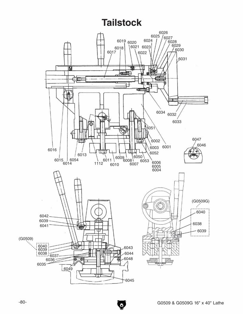
-80- G0509 & G0509G 16" x 40" Lathe
Tailstock
1112
6001
6002
6003
6004600560066007
60086009
60106011
6013
60146015
6016
60176018
6019 60206021
60226023
60246025
60266027602860296030
6031
6032
6033
6034
6035
6041
6042
6043
6044
6045
6046
6047
6048
6049
6050
6051
6052
60536054
6039
60366037
603860396040
(G0509)
6038
6039
6040
(G0509G)

G0509 & G0509G 16" x 40" Lathe -81-
Tailstock Parts ListREF PART # DESCRIPTION REF PART # DESCRIPTION1112 P05091112 SHAFT 6028 PK23M KEY 5 X 5 X 25MM6001 P05096001 TAILSTOCK (G0509) 6029 PSS24M SET SCREW M5-.8 X 25
P0509G6001 TAILSTOCK (G0509G) 6030 P05096030 PLUG6002 PS38M PHLP HD SCR M4-.7 X 10 6031 P05096031 HAND WHEEL6003 P05096003 BEDWAY WIPER 6032 P05096032 SHOULDER BOLT6004 PB116M HEX BOLT M10-1.5 X 45 6033 P05096033 HANDLE6005 PLW06M LOCK WASHER 10MM 6034 PSB15M CAP SCREW M5-.8 X 206006 PLW06M LOCK WASHER 10MM 6035 PSS01M SET SCREW M6-1 X 106007 P05096007 GIB 6036 PSS01M SET SCREW M6-1 X 106008 P05096008 GIB SCREW 6037 P05096037 ADJUSTING BLOCK6009 P05096009 TAIL STOCK BASE (G0509) 6038 P05096038 CLAMPING HUB (G0509)
P0509G6009 TAIL STOCK BASE (G0509G) P0509G6038 RECIEVER HUB (G0509G)6010 P05096010 CLAMPING BLOCK 6039 PRP56M ROLL PIN 4 X 25MM6011 PB121M HEX BOLT M12-1.75 X 100 PK23M KEY 5 X 5 X 25 (G0509G)6013 PRP24M ROLL PIN 5 X 16MM 6040 P05096040 LEVER (G0509)6014 PSS64M SET SCREW M6-1 X 15 P0509G6040 LEVER (G0509G)6015 P05096015 KEY 6041 P05096041 SHAFT6016 P05096016 QUILL (G0509) 6042 P05096042 LEVER
P0509G6016 QUILL (G0509G) 6043 PSB05M CAP SCREW M8-1.25 X 506017 P05096017 FEED SCREW (G0509) 6044 P05096044 BEDWAY WIPER
P0509G6017 FEED SCREW (G0509G) 6045 PW06M FLAT WASHER 12MM6018 P05096018 FEED NUT 6046 P05096046 RIVET 2 X 8MM6019 PSS11M SET SCREW M6-1 X 16 6047 P05096047 OFFSET INDICATOR PLATE6020 P05094064 BALL OILER 8MM 6048 P05096048 BEDWAY WIPER PLATE6021 P05096021 BRACKET 6049 P05096049 BEDWAY WIPER PLATE6022 P8104 THRUST BEARING 8104 6050 PB76M HEX BOLT M12-1.75 X 1106023 P05096023 DIAL 6051 P05096051 HIGH NUT M12-1.756024 PR37M EXT RETAINING RING 32MM 6052 PW04M FLAT WASHER 10MM6025 P05096025 SEALING RING 6053 P05096053 CLAMPING BLOCK6026 P05092156 STEEL BALL 6.5MM 6054 PW04M FLAT WASHER 10MM6027 P05096027 FLAT SPRING 0.6 X 5 X 16MM
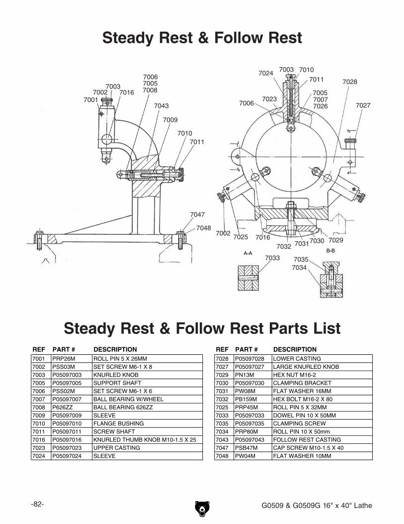
-82- G0509 & G0509G 16" x 40" Lathe
Parts List
Steady Rest & Follow Rest
7001
7002
7003 70057006
70077008
7009
70107011
7016
7023
70247028
7027
70297030703170327025
7033 70357034
7043
7047
7048
70167002
7006
7003 7010
7011
7005
7026
REF PART # DESCRIPTION REF PART # DESCRIPTION7001 PRP26M ROLL PIN 5 X 26MM 7028 P05097028 LOWER CASTING7002 PSS03M SET SCREW M6-1 X 8 7027 P05097027 LARGE KNURLED KNOB7003 P05097003 KNURLED KNOB 7029 PN13M HEX NUT M16-27005 P05097005 SUPPORT SHAFT 7030 P05097030 CLAMPING BRACKET7006 PSS02M SET SCREW M6-1 X 6 7031 PW08M FLAT WASHER 16MM7007 P05097007 BALL BEARING W/WHEEL 7032 PB159M HEX BOLT M16-2 X 807008 P626ZZ BALL BEARING 626ZZ 7025 PRP45M ROLL PIN 5 X 32MM7009 P05097009 SLEEVE 7033 P05097033 DOWEL PIN 10 X 50MM7010 P05097010 FLANGE BUSHING 7035 P05097035 CLAMPING SCREW7011 P05097011 SCREW SHAFT 7034 PRP80M ROLL PIN 10 X 50mm7016 P05097016 KNURLED THUMB KNOB M10-1.5 X 25 7043 P05097043 FOLLOW REST CASTING7023 P05097023 UPPER CASTING 7047 PSB47M CAP SCREW M10-1.5 X 407024 P05097024 SLEEVE 7048 PW04M FLAT WASHER 10MM
Steady Rest & Follow Rest Parts List

G0509 & G0509G 16" x 40" Lathe -83-
Electrical & Coolant System8006
8020
8023V2
8011
8010
8012 1302-11302
130280128012-1
8026
8004
8003
8002
8001
8019-1
80088009
80188019
80278027
8026
8021
8022
8006-1
8024

-84- G0509 & G0509G 16" x 40" Lathe
Electrical & Coolant System Parts ListREF PART # DESCRIPTION REF PART # DESCRIPTION
8012 P05098012 CONTACTOR SIEMENS 22E, 24V1302 P05091302 CONTACTOR SIEMENS 40E, 24V8012-1 P05098012-1 THERMAL RELAY SIEMENS, 1302-1 P05091302-1 THERMAL RELAY SIEMENS,
3UA52 10-16 AMP 0.05-0.32 AMP8018 P05098018 PUMP8001 P05098001 POWER LAMP8019 P05098019 PUMP MOTOR 220V 3-PH8002 P05098002 PUMP SWITCH8019-1 P05098019-1 PUMP POWER CORD ASSY8003 P05098003 EMERGENCY STOP SWITCH8020 P05098020 CIRCUIT BREAKER SET8004 P05098004 JOG BUTTON8021 P05098021 LIMIT SWITCH8006 P05098006 WORK LAMP ASSEMBLY8022 P05098022 40-POST TERMINAL BLOCK8006-1 P05098006-1 BULB8023 P05098023 TRANSFORMER8008 P05098008 CUTTING FLUID TUBE KIT8024 P05098024 MAIN POWER BOX8009 P0509G8009 TAILSTOCK FLUID TUBE KIT (G0509G)8026 P05098026 MAIN POWER ON/OFF SWITCH8010 P05098010 FUSE HOUSING8027 P05098027 MOTOR ROTATION LIMIT SWITCH8011 P05098011 FUSE HOUSING
Parts List
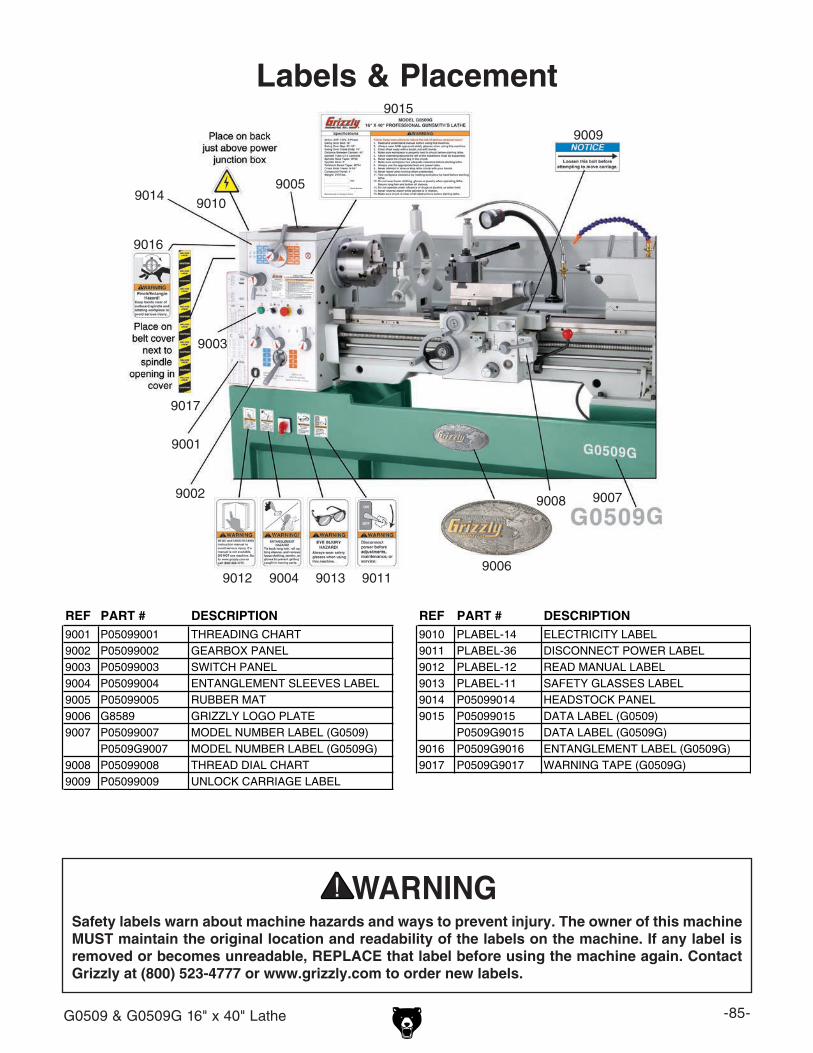
G0509 & G0509G 16" x 40" Lathe -85-
Labels & Placement
Safety labels warn about machine hazards and ways to prevent injury. The owner of this machine MUST maintain the original location and readability of the labels on the machine. If any label is removed or becomes unreadable, REPLACE that label before using the machine again. Contact Grizzly at (800) 523-4777 or www.grizzly.com to order new labels.
9010
9006
9007
9009
9011901390049012
9017
9016
9015
9001
9002
9014
9008
9003
9005
REF PART # DESCRIPTION REF PART # DESCRIPTION9001 P05099001 THREADING CHART 9010 PLABEL-14 ELECTRICITY LABEL9002 P05099002 GEARBOX PANEL 9011 PLABEL-36 DISCONNECT POWER LABEL9003 P05099003 SWITCH PANEL 9012 PLABEL-12 READ MANUAL LABEL9004 P05099004 ENTANGLEMENT SLEEVES LABEL 9013 PLABEL-11 SAFETY GLASSES LABEL9005 P05099005 RUBBER MAT 9014 P05099014 HEADSTOCK PANEL9006 G8589 GRIZZLY LOGO PLATE 9015 P05099015 DATA LABEL (G0509)9007 P05099007 MODEL NUMBER LABEL (G0509) P0509G9015 DATA LABEL (G0509G)
P0509G9007 MODEL NUMBER LABEL (G0509G) 9016 P0509G9016 ENTANGLEMENT LABEL (G0509G)9008 P05099008 THREAD DIAL CHART 9017 P0509G9017 WARNING TAPE (G0509G)9009 P05099009 UNLOCK CARRIAGE LABEL

-86- G0509 & G0509G 16" x 40" Lathe
Grizzly Industrial, Inc. warrants every product it sells for a period of 1 year to the original purchaser from the date of purchase. This warranty does not apply to defects due directly or indirectly to misuse, abuse, negligence, accidents, repairs or alterations or lack of maintenance. This is Grizzly’s sole written warranty and any and all warranties that may be implied by law, including any merchantability or fitness, for any par-ticular purpose, are hereby limited to the duration of this written warranty. We do not warrant or represent that the merchandise complies with the provisions of any law or acts unless the manufacturer so warrants. In no event shall Grizzly’s liability under this warranty exceed the purchase price paid for the product and any legal actions brought against Grizzly shall be tried in the State of Washington, County of Whatcom.
We shall in no event be liable for death, injuries to persons or property or for incidental, contingent, special, or consequential damages arising from the use of our products.
To take advantage of this warranty, contact us by mail or phone and give us all the details. We will then issue you a “Return Number,’’ which must be clearly posted on the outside as well as the inside of the carton. We will not accept any item back without this number. Proof of purchase must accompany the merchandise.
The manufacturers reserve the right to change specifications at any time because they constantly strive to achieve better quality equipment. We make every effort to ensure that our products meet high quality and durability standards and we hope you never need to use this warranty.
Please feel free to write or call us if you have any questions about the machine or the manual.
Thank you again for your business and continued support. We hope to serve you again soon.
WARRANTY AND RETURNS

G0509 & G0509G 16" x 40" Lathe -87-
CU
T A
LON
G D
OT
TE
D L
INE
Name _____________________________________________________________________________
Street _____________________________________________________________________________
City _______________________ State _________________________ Zip _____________________
Phone # ____________________ Email _________________________________________________
Model # ____________________ Order # _______________________ Serial # __________________
WARRANTY CARD
The following information is given on a voluntary basis. It will be used for marketing purposes to help us develop better products and services. Of course, all information is strictly confidential.
1. How did you learn about us? ____ Advertisement ____ Friend ____ Catalog ____ Card Deck ____ Website ____ Other:
2. Which of the following magazines do you subscribe to?
3. What is your annual household income? ____ $20,000-$29,000 ____ $30,000-$39,000 ____ $40,000-$49,000 ____ $50,000-$59,000 ____ $60,000-$69,000 ____ $70,000+
4. What is your age group? ____ 20-29 ____ 30-39 ____ 40-49 ____ 50-59 ____ 60-69 ____ 70+
5. How long have you been a woodworker/metalworker? ____ 0-2 Years ____ 2-8 Years ____ 8-20 Years ____20+ Years
6. How many of your machines or tools are Grizzly? ____ 0-2 ____ 3-5 ____ 6-9 ____10+
7. Do you think your machine represents a good value? _____Yes _____No
8. Would you recommend Grizzly Industrial to a friend? _____Yes _____No
9. Would you allow us to use your name as a reference for Grizzly customers in your area? Note: We never use names more than 3 times. _____Yes _____No
10. Comments: _____________________________________________________________________
_________________________________________________________________________________
_________________________________________________________________________________
_________________________________________________________________________________
____ Cabinetmaker & FDM____ Family Handyman____ Hand Loader____ Handy____ Home Shop Machinist____ Journal of Light Cont.____ Live Steam____ Model Airplane News____ Old House Journal____ Popular Mechanics
____ Popular Science____ Popular Woodworking____ Precision Shooter____ Projects in Metal____ RC Modeler____ Rifle____ Shop Notes____ Shotgun News____ Today’s Homeowner____ Wood
____ Wooden Boat____ Woodshop News____ Woodsmith____ Woodwork____ Woodworker West____ Woodworker’s Journal____ Other:

TAPE ALONG EDGES--PLEASE DO NOT STAPLE
FOLD ALONG DOTTED LINE
FOLD ALONG DOTTED LINE
GRIZZLY INDUSTRIAL, INC.P.O. BOX 2069BELLINGHAM, WA 98227-2069
PlaceStampHere
Name_______________________________
Street_______________________________
City______________State______Zip______
Send a Grizzly Catalog to a friend: