OWNER'S MANUAL - Grizzlycdn0.grizzly.com/manuals/g9972z_m.pdf · this lathe features an open...
76
MODEL G9972Z 11" x 26" LIGHT-DUTY LATHE w/GEARBOX OWNER'S MANUAL COPYRIGHT © JULY, 2008 BY GRIZZLY INDUSTRIAL, INC., REVISED JULY, 2014 (ST) WARNING: NO PORTION OF THIS MANUAL MAY BE REPRODUCED IN ANY SHAPE OR FORM WITHOUT THE WRITTEN APPROVAL OF GRIZZLY INDUSTRIAL, INC. #TS10714 PRINTED IN CHINA
Transcript of OWNER'S MANUAL - Grizzlycdn0.grizzly.com/manuals/g9972z_m.pdf · this lathe features an open...

MODEL G9972Z11" x 26" LIGHT-DUTYLATHE w/GEARBOX
OWNER'S MANUAL
COPYRIGHT © JULY, 2008 BY GRIZZLY INDUSTRIAL, INC., REVISED JULY, 2014 (ST)WARNING: NO PORTION OF THIS MANUAL MAY BE REPRODUCED IN ANY SHAPE
OR FORM WITHOUT THE WRITTEN APPROVAL OF GRIZZLY INDUSTRIAL, INC. #TS10714 PRINTED IN CHINA

This manual provides critical safety instructions on the proper setup, operation, maintenance, and service of this machine/tool. Save this document, refer to it often, and use it to instruct other operators.
Failure to read, understand and follow the instructions in this manual may result in fire or serious personal injury—including amputation, electrocution, or death.
The owner of this machine/tool is solely responsible for its safe use. This responsibility includes but is not limited to proper installation in a safe environment, personnel training and usage authorization, proper inspection and maintenance, manual availability and compre-hension, application of safety devices, cutting/sanding/grinding tool integrity, and the usage of personal protective equipment.
The manufacturer will not be held liable for injury or property damage from negligence, improper training, machine modifications or misuse.
Some dust created by power sanding, sawing, grinding, drilling, and other construction activities contains chemicals known to the State of California to cause cancer, birth defects or other reproductive harm. Some examples of these chemicals are:
• Lead from lead-based paints.• Crystalline silica from bricks, cement and other masonry products.• Arsenic and chromium from chemically-treated lumber.
Your risk from these exposures varies, depending on how often you do this type of work. To reduce your exposure to these chemicals: Work in a well ventilated area, and work with approved safety equip-ment, such as those dust masks that are specially designed to filter out microscopic particles.
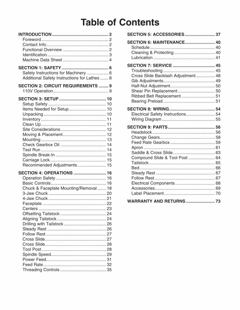
Table of ContentsSECTION 5: ACCESSORIES ......................... 37
SECTION 6: MAINTENANCE ......................... 40Schedule ...................................................... 40Cleaning & Protecting .................................. 40Lubrication ................................................... 41
SECTION 7: SERVICE ................................... 45Troubleshooting ........................................... 45Cross Slide Backlash Adjustment ................ 48Gib Adjustments........................................... 49Half-Nut Adjustment ..................................... 50Shear Pin Replacement ............................... 50Ribbed Belt Replacement ............................ 51Bearing Preload ........................................... 51
SECTION 8: WIRING ...................................... 54Electrical Safety Instructions ........................ 54Wiring Diagram ............................................ 55
SECTION 9: PARTS ....................................... 56Headstock .................................................... 56Change Gears.............................................. 58Feed Rate Gearbox ..................................... 59Apron ........................................................... 61Saddle & Cross Slide ................................... 63Compound Slide & Tool Post ...................... 64Tailstock ....................................................... 65Bed ............................................................... 66Steady Rest ................................................. 67Follow Rest .................................................. 67Electrical Components ................................. 68Accessories .................................................. 69Label Placement .......................................... 70
WARRANTY AND RETURNS ........................ 73
INTRODUCTION ............................................... 2Foreword ........................................................ 2Contact Info.................................................... 2Functional Overview ...................................... 2Identification ................................................... 3Machine Data Sheet ...................................... 4
SECTION 1: SAFETY ....................................... 6Safety Instructions for Machinery .................. 6Additional Safety Instructions for Lathes ....... 8
SECTION 2: CIRCUIT REQUIREMENTS ........ 9110V Operation .............................................. 9
SECTION 3: SETUP ....................................... 10Setup Safety ................................................ 10Items Needed for Setup ............................... 10Unpacking .................................................... 10Inventory ...................................................... 11Clean Up ...................................................... 11Site Considerations ...................................... 12Moving & Placement .................................... 12Mounting ...................................................... 13Check Gearbox Oil ...................................... 14Test Run ...................................................... 14Spindle Break-In .......................................... 15Carriage Lock............................................... 15Recommended Adjustments ........................ 15
SECTION 4: OPERATIONS ........................... 16Operation Safety .......................................... 16Basic Controls .............................................. 16Chuck & Faceplate Mounting/Removal ....... 183-Jaw Chuck ................................................ 204-Jaw Chuck ................................................ 21Faceplate ..................................................... 22Centers ........................................................ 23Offsetting Tailstock ...................................... 24Aligning Tailstock ......................................... 24Drilling with Tailstock ................................... 26Steady Rest ................................................. 26Follow Rest .................................................. 27Cross Slide................................................... 27Cross Slide................................................... 28Tool Post ...................................................... 28Spindle Speed.............................................. 29Power Feed.................................................. 31Feed Rate .................................................... 32Threading Controls ...................................... 35

-2- G9972Z 11" x 26" Lathe w/Gearbox
INTRODUCTION
Foreword
We are proud to offer the Model G9972Z 11" x 26" Light-Duty Lathe w/Gearbox. This machine is part of a growing Grizzly family of fine met-alworking machinery. When used according to the guidelines set forth in this manual, you can expect years of trouble-free, enjoyable operation and proof of Grizzly’s commitment to customer satisfaction.
The specifications, drawings, and photographs illustrated in this manual represent the Model G9972Z when the manual was prepared. However, owing to Grizzly’s policy of continuous improve-ment, changes may be made at any time with no obligation on the part of Grizzly. For your conve-nience, we always keep current Grizzly manuals available on our website at www.grizzly.com. Any updates to your machine will be reflected in these manuals as soon as they are complete. Visit our site often to check for the latest updates to this manual!
We stand behind our machines. If you have any service questions, parts requests or general ques-tions about the machine, please call or write us at the location listed below.
Grizzly Industrial, Inc.1203 Lycoming Mall Circle
Muncy, PA 17756Phone: (570) 546-9663
Fax: (800) 438-5901E-Mail: [email protected]
If you have any comments regarding this manual, please write to us at the address below:
Grizzly Industrial, Inc.C/O Technical Documentation Manager
P.O. Box 2069Bellingham, WA 98227-2069Email: [email protected]
Contact Info
Functional Overview
The primary purpose of the metal lathe is to make concentric cuts in metal stock. With the lathe, round stock can be made perfectly con-centric, threaded, drilled, knurled, bored, tapered, etc. Square stock can be made into precision round shafts used for axles, spindles, leadscrews, punches, etc.
The maximum size of workpiece a lathe can cut is determined by the swing, which is the distance from the center line of the spindle to the bed, and the throw, which is the maximum distance between the tailstock and the spindle. However, this lathe features an open spindle that allows lon-ger workpieces to extend through the headstock.
During typical operations, the lathe cuts with a fixed cutting tool that is positioned against a rotat-ing workpiece. To rotate a workpiece, the operator centers it on a clamping device called a chuck or faceplate, then securely clamps the chuck or faceplate to the spindle so it will not fly loose dur-ing operation.
The spindle connects to the motor through a series of pulleys that control the speed the spindle can rotate, which allows the operator different options for cutting based on the type of metal and size of workpiece.
The cutting tool is mounted on a tool post, which is positioned by three different bases that move linearly in their own designated direction. The bottom base is the carriage, which moves left and right, and is equipped with a power feed system for automated cutting and threading operations. The middle base is the cross slide, which moves in and out. The top base is the compound slide, which moves diagonally.
The lathe is also outfitted with a support device called a tailstock. The tailstock is mounted on the lathe bed opposite of the spindle, and it moves toward or away from the spindle and can be locked against the bed to firmly support the end of a long workpiece.
G9972Z 11" x 26" Lathe w/Gearbox -3-
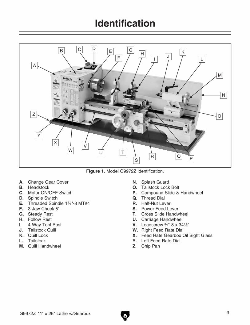
Figure 1. Model G9972Z identification.
A. Change Gear CoverB. HeadstockC. Motor ON/OFF SwitchD. Spindle SwitchE. Threaded Spindle 1 3⁄4"-8 MT#4F. 3-Jaw Chuck 5"G. Steady RestH. Follow RestI. 4-Way Tool PostJ. Tailstock QuillK. Quill LockL. TailstockM. Quill Handwheel
Identification
A
B C DE
F
GH
IJ
K
L
M
O
PQRS
TUV
W
X
Y
Z
N. Splash GuardO. Tailstock Lock BoltP. Compound Slide & HandwheelQ. Thread DialR. Half-Nut LeverS. Power Feed LeverT. Cross Slide HandwheelU. Carriage HandwheelV. Leadscrew 3⁄4"-8 x 34 1⁄2"W. Right Feed Rate DialX. Feed Rate Gearbox Oil Sight GlassY. Left Feed Rate DialZ. Chip Pan
N

-4- G9972Z 11" x 26" Lathe w/Gearbox
The information contained herein is deemed accurate as of 9/26/2017 and represents our most recent product specifications.Due to our ongoing improvement efforts, this information may not accurately describe items previously purchased. PAGE 1 OF 3Model G9972Z
MACHINE DATASHEET
Customer Service #: (570) 546-9663 · To Order Call: (800) 523-4777 · Fax #: (800) 438-5901
MODEL G9972Z 11" X 26" BENCH LATHE W/ GEARBOXProduct Dimensions:
Weight.............................................................................................................................................................. 490 lbs.Width (side-to-side) x Depth (front-to-back) x Height........................................................................... 51 x 23 x 19 in.Footprint (Length x Width)............................................................................................................................ 51 x 18 in.
Shipping Dimensions:
Type.......................................................................................................................................................... Wood CrateContent........................................................................................................................................................... MachineWeight.............................................................................................................................................................. 560 lbs.Length x Width x Height....................................................................................................................... 58 x 30 x 26 in.Must Ship Upright................................................................................................................................................... Yes
Electrical:
Power Requirement........................................................................................................... 110V, Single-Phase, 60 HzPrewired Voltage.................................................................................................................................................. 110VFull-Load Current Rating..................................................................................................................................... 13.6AMinimum Circuit Size.............................................................................................................................................. 20AConnection Type....................................................................................................................................... Cord & PlugPower Cord Included.............................................................................................................................................. YesPower Cord Length................................................................................................................................................. 4 ft.Power Cord Gauge......................................................................................................................................... 12 AWGPlug Included.......................................................................................................................................................... YesIncluded Plug Type................................................................................................................................................ 5-15Switch Type........................................................................................... ON/OFF Push Button Switch w/Safety Cover
Motors:Main
Horsepower................................................................................................................................................ 1 HPPhase............................................................................................................................................ Single-PhaseAmps......................................................................................................................................................... 13.6ASpeed................................................................................................................................................ 1725 RPMType................................................................................................................. TEFC Capacitor-Start InductionPower Transfer .................................................................................................................................. Belt DriveBearings..................................................................................................... Shielded & Permanently Lubricated
Main Specifications:
Operation Info
Swing Over Bed................................................................................................................................... 10-1/2 in.Distance Between Centers........................................................................................................................ 26 in.Swing Over Cross Slide......................................................................................................................... 6-3/8 in.Swing Over Saddle................................................................................................................................ 6-3/8 in.Maximum Tool Bit Size............................................................................................................................. 1/2 in.Compound Travel.................................................................................................................................. 3-1/2 in.Carriage Travel.......................................................................................................................................... 23 in.Cross Slide Travel....................................................................................................................................... 7 in.
Machine Data Sheet
data sheet

G9972Z 11" x 26" Lathe w/Gearbox -5-
The information contained herein is deemed accurate as of 9/26/2017 and represents our most recent product specifications.Due to our ongoing improvement efforts, this information may not accurately describe items previously purchased. PAGE 2 OF 3Model G9972Z
Headstock Info
Spindle Bore................................................................................................................................................ 1 in.Spindle Size........................................................................................................................................... 1-3/4 in.Spindle Taper............................................................................................................................................ MT#4Spindle Threads......................................................................................................................................... 8 TPINumber of Spindle Speeds............................................................................................................................... 6Spindle Speeds....................................................................................................................... 150 – 2400 RPMSpindle Type....................................................................................................................................... ThreadedSpindle Bearings......................................................................................................................... Tapered Roller
Tailstock Info
Tailstock Quill Travel............................................................................................................................ 2-1/2 in.Tailstock Taper.......................................................................................................................................... MT#3Tailstock Barrel Diameter..................................................................................................................... 1.125 in.
Threading Info
Number of Longitudinal Feeds....................................................................................................................... 12Range of Longitudinal Feeds........................................................................................ 0.0022 – 0.0150 in./rev.Number of Inch Threads................................................................................................................................. 24Range of Inch Threads...................................................................................................................... 8 – 56 TPINumber of Metric Threads.............................................................................................................................. 10Range of Metric Threads............................................................................................................... 0.5 – 3.0 mm
Dimensions
Bed Width.................................................................................................................................................... 6 in.Carriage Leadscrew Diameter.................................................................................................................. 3/4 in.Leadscrew TPI........................................................................................................................................... 8 TPICarriage Leadscrew Length................................................................................................................ 34-1/2 in.Steady Rest Capacity......................................................................................................................... 1/4 – 2 in.Follow Rest Capacity.......................................................................................................................... 1/4 – 2 in.Faceplate Size............................................................................................................................................. 8 in.
Other
Optional Stand......................................................................................................................................... G9973
Construction
Base.............................................................................................................................................. Formed SteelHeadstock............................................................................................................................................ Cast IronEnd Gears.................................................................................................................................................. SteelBed.................................................................................................. Hardened and Precision-Ground Cast IronBody..................................................................................................................................................... Cast IronPaint Type/Finish...................................................................................................................................... Epoxy
Other Specifications:
Country of Origin ................................................................................................................................................ ChinaWarranty ........................................................................................................................................................... 1 YearApproximate Assembly & Setup Time .............................................................................................................. 1 HourSerial Number Location .................................................................................................................................. ID LabelISO 9001 Factory .................................................................................................................................................... NoCertified by a Nationally Recognized Testing Laboratory (NRTL) .......................................................................... No
Features:
Easy to Read Control PanelEmergency StopLong Bed Accommodates 26" Between CentersThreading Dial
-6- G9972Z 11" x 26" Lathe w/Gearbox
Safety Instructions for Machinery
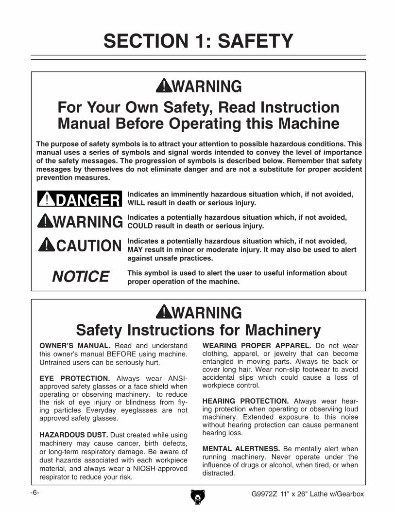
For Your Own Safety, Read Instruction Manual Before Operating this Machine
The purpose of safety symbols is to attract your attention to possible hazardous conditions. This manual uses a series of symbols and signal words intended to convey the level of importance of the safety messages. The progression of symbols is described below. Remember that safety messages by themselves do not eliminate danger and are not a substitute for proper accident prevention measures.
Indicates a potentially hazardous situation which, if not avoided, MAY result in minor or moderate injury. It may also be used to alert against unsafe practices.
Indicates a potentially hazardous situation which, if not avoided, COULD result in death or serious injury.
Indicates an imminently hazardous situation which, if not avoided, WILL result in death or serious injury.
This symbol is used to alert the user to useful information about proper operation of the machine.NOTICE
WEARING PROPER APPAREL. Do not wear clothing, apparel, or jewelry that can become entangled in moving parts. Always tie back or cover long hair. Wear non-slip footwear to avoid accidental slips which could cause a loss of workpiece control.
HEARING PROTECTION. Always wear hear-ing protection when operating or observiing loud machinery. Extended exposure to this noise without hearing protection can cause permanent hearing loss.
MENTAL ALERTNESS. Be mentally alert when running machinery. Never operate under the influence of drugs or alcohol, when tired, or when distracted.
OWNER’S MANUAL. Read and understand this owner’s manual BEFORE using machine. Untrained users can be seriously hurt.
EYE PROTECTION. Always wear ANSI-approved safety glasses or a face shield when operating or observing machinery. to reduce the risk of eye injury or blindness from fly-ing particles Everyday eyeglasses are not approved safety glasses.
HAzARDOUS DUST. Dust created while using machinery may cause cancer, birth defects, or long-term respiratory damage. Be aware of dust hazards associated with each workpiece material, and always wear a NIOSH-approved respirator to reduce your risk.
Safety Instructions for Machinery
SECTION 1: SAFETY

G9972Z 11" x 26" Lathe w/Gearbox -7-
DISCONNECTING POWER SUPPLY. Always disconnect machine from power supply before servicing, adjusting, or changing cutting tools (bits, blades, cutters, etc.). Make sure switch is in OFF position before reconnecting to avoid an unexpected or unintentional start.
INTENDED USE. Only use the machine for its intended purpose and only use recommended accessories. Never stand on machine, modify it for an alternative use, or outfit it with non-approved accessories.
STABLE MACHINE. Unexpected movement during operations greatly increases the risk of injury and loss of control. Verify machines are stable/secure and mobile bases (if used) are locked before starting.
FORCING MACHINERY. Do not force machine. It will do the job safer and better at the rate for which it was designed.
GUARDS & COVERS. Guards and covers can protect you from accidental contact with mov-ing parts or flying debris. Make sure they are properly installed, undamaged, and working correctly before using machine.
REMOVING TOOLS. Never leave adjustment tools, chuck keys, wrenches, etc. in or on machine—especially near moving parts. Verify removal before starting!
AWKWARD POSITIONS. Keep proper foot-ing and balance at all times when operating machine. Do not overreach! Avoid awkward hand positions that make workpiece control dif-ficult or increase the risk of accidental injury.
DANGEROUS ENVIRONMENTS. Do not use machinery in wet locations, cluttered areas, around flammables, or in poorly-lit areas. Keep work area clean, dry, and well lighted to mini-mize risk of injury.
Safety Instructions for MachineryAPPROVED OPERATION. Untrained operators can be seriously hurt by machinery. Only allow trained or properly supervised people to use machine. When machine is not being used, dis-connect power, remove switch keys, or lock-out machine to prevent unauthorized use—especially around children. Make workshop kid proof!
CHILDREN & BYSTANDERS. Keep children and bystanders a safe distance away from work area. Stop using machine if children or bystand-ers become a distraction.
FEED DIRECTION. Unless otherwise noted, feed work against the rotation of blades or cutters. Feeding in the same direction of rotation may pull your hand into the cut.
SECURING WORKPIECE. When required, use clamps or vises to secure workpiece. A secured workpiece protects hands and frees both of them to operate the machine.
UNATTENDED OPERATION. Never leave machine running while unattended. Turn machine Off and ensure all moving parts completely stop before walking away.
MAINTENANCE & INSPECTION. A machine that is not properly maintained may operate unpre-dictably. Follow all maintenance instructions and lubrication schedules to keep machine in good working condition. Regularly inspect machine for loose bolts, alignment of critical parts, binding, or any other conditions that may affect safe opera-tion. Always repair or replace damaged or mis-adjusted parts before operating machine.
EXPERIENCING DIFFICULTIES. If at any time you are experiencing difficulties performing the intended operation, stop using the machine! Contact our Technical Support Department at (570) 546-9663.

-8- G9972Z 11" x 26" Lathe w/Gearbox
Additional Safety Instructions for Lathes
No list of safety guidelines can be complete. Every shop environment is different. Always consider safety first, as it applies to your individual working conditions. Use this and other machinery with caution and respect. Failure to do so could result in serious per-sonal injury, damage to equipment, or poor work results.
Like all machinery there is potential danger when operating this machine. Accidents are frequently caused by lack of familiarity or failure to pay attention. Use this machine with respect and caution to decrease the risk of operator injury. If normal safety pre-cautions are overlooked or ignored, serious personal injury may occur.
1. UNDERSTANDING THE MACHINE: Read and understand this manual before operat-ing the machine.
2. CLEANING MACHINE: To avoid lacera-tions, do not clear chips by hand. Use a brush, and never clear chips while the lathe is operating.
3. USING CORRECT TOOLING: Always select the right cutter for the job, and make sure cutters are sharp. The right tool decreases strain on the lathe components and reduces the risk of unsafe cutting.
4. ELIMINATING A PROJECTILE HAZARD: Always remove the chuck key after use, and never walk away from the lathe with the chuck key installed.
5. SECURING A WORKPIECE: Make sure the workpiece is properly held in the chuck before starting the lathe. A workpiece thrown from the chuck could cause severe injury.
6. AVOIDING OVERLOADS: Always use the appropriate spindle speed and feed rate.
7. AVOIDING ENTANGLEMENT INJURIES: Never attempt to slow or stop the lathe chuck; and tie back long hair, ponytails, loose clothing, and sleeves so they do not dangle.
8. PREVENTING A CUTTING TOOL/CHUCK CRASH: Always disengage the power feed and half-nut after completing a job.
9. AVOIDING STARTUP INJURIES: Make sure the workpiece, cutting tool, and tool post have adequate clearance before start-ing the lathe. Check the chuck saddle clearance before starting the lathe. Make sure the spindle RPM is set correctly for the workpiece diameter before starting the lathe. Large parts can be ejected from the chuck if the chuck speed is set too high.
10. CHUCK SAFETY: Chucks are surprisingly heavy and awkward to hold, so protect your hands and the bedways. Always use a chuck cradle or piece of plywood over the bedways.
11. WORKPIECE SUPPORT: Support a long workpiece if it extends outboard from the headstock so it will not wobble violently when the lathe is turned ON. If the workpiece extends more than 2.5 times its diameter from the chuck, support it by a center or steady rest, or it may deflect and fall out of the chuck while cutting.
12. MAINTAINING A SAFE WORKPLACE: Never leave lathe unattended while it is run-ning.

G9972Z 11" x 26" Lathe w/Gearbox -9-
Figure 2. Typical 5-15 plug and receptacle.
Grounding Prong
Neutral Hot
5-15 PLUG
GROUNDED5-15 RECEPTACLE
110V Operation
Full Load Amperage DrawThis machine draws the following amps under maximum load:
Amp Draw ........................................... 13.6 Amps
Power Supply Circuit RequirementsYou MUST connect your machine to a grounded circuit that is rated for the amperage given below. Never replace a circuit breaker on an existing cir-cuit with one of higher amperage without consult-ing a qualified electrician to ensure compliance with wiring codes. If you are unsure about the wiring codes in your area or you plan to con-nect your machine to a shared circuit, consult a qualified electrician.
Minimum Circuit Size .............................20 Amps
This machine MUST have a ground prong in the plug to help ensure that it is grounded. DO NOT remove ground prong from plug to fit into a two-pronged outlet! If the plug will not fit the outlet, have the proper outlet installed by a qualified electrician.
Extension CordsWe do not recommend using extension cords, but if you find it absolutely necessary:
• Use at least a 14 gauge cord that does not exceed 50 feet in length!
• The extension cord must have a ground wire and plug pin.
• A qualified electrician MUST size cords over 50 feet long to prevent motor damage.
SECTION 2: CIRCUIT REQUIREMENTS
Serious personal injury could occur if you connect the machine to power before com-pleting the setup process. DO NOT connect the machine to the power until instructed later in this manual.
Electrocution or fire could result if machine is not grounded and installed in compliance with electrical codes. Compliance MUST be verified by a qualified electrician!
Power Connection DeviceThe Model G9972Z comes with a 5-15 plug, simi-lar to Figure 2, to connect the machine to power.

-10- G9972Z 11" x 26" Lathe w/Gearbox
Wear safety glasses dur-ing the entire setup pro-cess!
This machine presents serious injury hazards to untrained users. Read through this entire manu-al to become familiar with the controls and opera-tions before starting the machine!
Setup Safety
SECTION 3: SETUP
The following items are needed to complete the setup process, but are not included with your machine:
Description Qty• Assistant ..................................................... 1• Safety Glasses ............... 1 For Each Person• Machinist's Level ........................................ 1• Lifting Straps (rated for at least 750 lbs) .... 2• Power Lifting Equipment (rated for at least
750 lbs) ....................................... As Needed• Machine Mounting Hardware ..... As Needed• NGLI #2 Grease ......................... As Needed• ISO 68 or Equivalent Lubricant .. As Needed
Items Needed for Setup
Your machine was carefully packaged for safe transportation. Remove the packaging materials from around your machine and inspect it. If you discover the machine is damaged, please imme-diately call Customer Service at (570) 546-9663 for advice.
Save the containers and all packing materials for possible inspection by the carrier or its agent. Otherwise, filing a freight claim can be difficult.
When you are completely satisfied with the condi-tion of your shipment, inventory the contents.
If any nonproprietary parts are missing (e.g. a nut or a washer), we will gladly replace them; or for the sake of expediency, replacements can be obtained at your local hardware store.
Unpacking
SUFFOCATION HAZARD!Immediately discard all plas-tic bags and packing materi-als to eliminate choking/suf-focation hazards for children and animals.
The Model G9972Z is a heavy machine. Serious personal injury may occur if safe moving methods are not used. To be safe, get assistance and use power equipment rated for at least 750 lbs. to move the shipping crate and remove the machine from the crate.

G9972Z 11" x 26" Lathe w/Gearbox -11-
Inventory
The following is a description of the main compo-nents shipped with your machine. Lay the compo-nents out to inventory them.
Note: If you can't find an item on this list, check the mounting location on the machine or examine the packaging materials carefully. Occasionally we pre-install certain components for shipping purposes.
Inventory: (Figure 3) QtyA. Lathe 11" x 26" (not shown) ........................ 1B. Faceplate 8" ............................................... 1C. Toolbox ....................................................... 1D. Steady Rest ................................................ 1E. Follow Rest ................................................. 1F. 4-Way Tool Post ......................................... 1G. 3-Jaw Chuck 5" .......................................... 1H. 4-Jaw Chuck 6 1⁄2" ....................................... 1I. 3-Jaw Chuck Key ....................................... 1J. Dead Center MT#4 ..................................... 1K. External Jaws for 3-Jaw Chuck .................. 3L. Dead Center MT#3 ..................................... 1M. Change Gears 28, 35, 63, 69, 70, 77, 78T ..........................................................1 EachN. Screwdrivers Standard/Phillips ..........1 EachO. Hex Wrenches 3, 4, 5, 6, 8mm .........1 EachP. Wrenches 8/10, 12/14, 17/19mm ........1 EachQ. 4-Jaw Chuck Key ....................................... 1R. V-belt 3L290 (not shown) ........................... 1S. Splash Pan (not shown) ............................. 1
Figure 3. Model G9972Z inventory.
B CD
E
FGH
I
J
K
LM
N
OPQ
The unpainted surfaces are coated with a waxy oil to prevent corrosion during shipment. Remove this protective coating with a solvent cleaner or degreaser, such as shown in Figure 4. For thor-ough cleaning, some parts must be removed. For optimum performance, clean all moving parts or sliding contact surfaces. Avoid chlo-rine-based solvents, such as acetone or brake parts cleaner that may damage painted surfac-es. Always follow the manufacturer’s instructions when using any type of cleaning product.
Clean Up
Gasoline and petroleum products have low flash points and can explode or cause fire if used to clean machinery. DO NOT use these products to clean the machinery.
Many cleaning solvents are toxic if inhaled. Minimize your risk by only using these products in a well ventilated area.
G2544—Solvent Cleaner & DegreaserA great product for removing the waxy shipping grease from your machine during clean up.
Figure 4. Cleaner/degreaser available from Grizzly.

-12- G9972Z 11" x 26" Lathe w/Gearbox
Floor LoadRefer to the Machine Data Sheet on Page 4 for the weight and footprint specifications of your machine. Some residential floors may require addi-tional reinforcement to support both the machine and operator. Make sure the workbench or stand you plan to use can safely handle the weight and vibration of the lathe and operational materials.
Placement LocationConsider existing and anticipated needs, size of material to be processed through each machine, and space for auxiliary stands, work tables or other machinery when establishing a location for your new machine. See Figure 5 for the minimum working clearances.
Children and visitors may be seriously injured if unsuper-vised around this machine. Lock entrances to the shop or disable start switch or power connection to prevent unsupervised use.
Site Considerations
Figure 5. Minimum working clearances.
65"
27"
Moving & Placement
The Model G9972Z is a heavy machine. Serious personal injury may occur if safe moving methods are not used. To be safe, get assistance and use power equipment rated for at least 750 lbs. to move the shipping crate and remove the machine from the crate.
To move and place your lathe:
1. Remove the top and side crating materials, and the chip pan, 4-jaw chuck, faceplate, and toolbox from the shipping pallet.
2. Position the chip pan on the selected mount-ing surface and use it as a template to pre-pare holes for the mounting hardware (refer to Mounting on Page 13).
3. Use the 17mm wrench to remove the hex nuts that secure the lathe to the shipping pal-let.
Only use lifting straps and power lifting equipment rated for at least 750 lbs. and in good working condition. If the lathe falls or tips over while moving it, serious personal injury and property damage could result.
G9972Z 11" x 26" Lathe w/Gearbox -13-
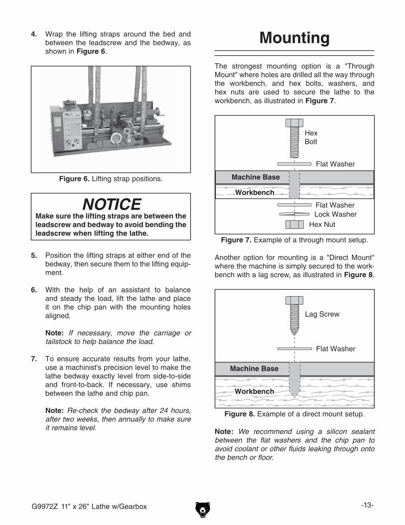
Figure 6. Lifting strap positions.
NOTICEMake sure the lifting straps are between the leadscrew and bedway to avoid bending the leadscrew when lifting the lathe.
5. Position the lifting straps at either end of the bedway, then secure them to the lifting equip-ment.
6. With the help of an assistant to balance and steady the load, lift the lathe and place it on the chip pan with the mounting holes aligned.
Note: If necessary, move the carriage or tailstock to help balance the load.
7. To ensure accurate results from your lathe, use a machinist's precision level to make the lathe bedway exactly level from side-to-side and front-to-back. If necessary, use shims between the lathe and chip pan.
Note: Re-check the bedway after 24 hours, after two weeks, then annually to make sure it remains level.
Mounting
The strongest mounting option is a "Through Mount" where holes are drilled all the way through the workbench, and hex bolts, washers, and hex nuts are used to secure the lathe to the workbench, as illustrated in Figure 7.
Machine Base
Workbench
HexBolt
Flat Washer
Flat Washer Lock Washer
Hex Nut
Figure 7. Example of a through mount setup.
Machine Base
Workbench
Lag Screw
Flat Washer
Figure 8. Example of a direct mount setup.
Another option for mounting is a "Direct Mount" where the machine is simply secured to the work-bench with a lag screw, as illustrated in Figure 8.
4. Wrap the lifting straps around the bed and between the leadscrew and the bedway, as shown in Figure 6.
Note: We recommend using a silicon sealant between the flat washers and the chip pan to avoid coolant or other fluids leaking through onto the bench or floor.

-14- G9972Z 11" x 26" Lathe w/Gearbox
Test Run
Once the assembly is complete, test run your machine to make sure it runs properly.
If, during the test run, you cannot easily locate the source of an unusual noise or vibration, stop using the machine immediately, then review the Troubleshooting on Page 45.
If you still cannot remedy a problem, contact our Tech Support at (570) 546-9663 for assistance.
To test run the machine:
1. Make sure you have read the safety instruc-tions at the beginning of the manual and that the machine is set up properly.
2. Read and understand the Basic Controls subsection on Page 16.
3. Make sure all tools and objects used during setup are cleared away from the machine.
4. Perform all lubrication procedures as instructed in the Lubrication subsection on Page 41.
6. Connect the machine to the power source.
7. Flip the spindle switch to the right "R" posi-tion—the spindle should rotate counterclock-wise and the leadscrew should turn clock-wise.
8. Lift the cover of the motor ON/OFF switch and turn the motor ON.
Note: Listen to and watch for abnormal noises or actions. The machine should run smoothly with little or no vibration or rubbing noises.
Strange or unusual noises should be inves-tigated and corrected before operating the machine further. Always disconnect the machine from power when investigating or correcting potential problems.
9. Flip the spindle switch to the center "O" posi-tion and wait for the spindle to come to a complete stop.
10. Turn the spindle switch to the left "L" posi-tion—the spindle should rotate clockwise and the leadscrew should turn counterclockwise.
5. Move the half-nut lever up to disengage the half-nut, and push the power feed lever down to disengage the carriage power feed, as shown in Figure 9.
Check Gearbox Oil
It is critical that you make sure there is oil in the feed rate gearbox before proceeding with the test run. Refer to the Lubrication instructions on Page 41 for more details on which type of oil to use, how much to use, and where to put it.
GEARBOXES MUSTBE FILLED WITH OIL!
NO OIL SHIPPED WITH MACHINE!
Refer to the Lubrication Section in this Manual
for RecommendedOil Type.
NOTICEALWAYS make sure the power feed lever and the half-nut lever are disengaged before starting the lathe to avoid carriage crashes with the headstock or tailstock.
Figure 9. Half-nut and power feed lever positions for Test Run.
Power Feed Lever Down (Horizontal)
Half-Nut Lever Up (Horizontal)

G9972Z 11" x 26" Lathe w/Gearbox -15-
NOTICESuccessfully complete all of the spindle break-in steps to avoid rapid deterioration of the spindle bearings and other related parts.
Spindle Break-In
For your convenience, the adjustments listed below have been performed at the factory.
However, because of the many variables involved with shipping, we recommend that you at least verify the following adjustments to ensure the best possible results from your new machine.
Step-by-step instructions for these adjustments can be found in the SERVICE section starting on Page 45.
Factory adjustments that should be verified:
• Cross slide backlash adjustment (Page 48)
• Gib adjustments (Page 49)
Recommended Adjustments
8. Turn the lathe OFF. The spindle break-in is complete and your lathe is ready for opera-tion.
1. DISCONNECT LATHE FROM POWER!
2. Make sure the lathe is properly lubricated (refer to Lubrication on Page 41 for detailed instructions).
3. Configure the spindle belt for the lowest spin-dle speed (refer to Spindle Speed on Page 29 for detailed instructions).
4. Connect the machine to power, turn the spin-dle switch to the "R" position to start spindle rotation in the counterclockwise direction, then let the lathe run for 10 minutes.
5. Stop the spindle rotation and wait until the spindle has come to a complete stop.
6. Start spindle rotation in the opposite clock-wise direction and let the lathe run for 10 minutes.
7. Disconnect the machine from power, then repeat Steps 4–6 for each of the spindle speeds.
Carriage Lock
The carriage is supplied with a lock bolt on the front right-hand side of the saddle (see Figure 10). This bolt locks the carriage in place for increased rigidity when making face cuts. This lock bolt must be loosened before attempting to move the car-riage manually or with the power feed.
11. Press the red button on the motor ON/OFF switch.
—If the motor stops, the emergency stop fea-ture of the switch is working as designed.
—If the motor does NOT stop, immediately disconnect the machine from power. The emergency stop feature is not working correctly. This safety feature must work properly before proceeding with regular operations. Call Tech Support for help.
12. After successfully completing all the Test Run steps, proceed to Spindle Break-In.
Figure 10. Carriage lock bolt.
Lock Bolt

-16- G9972Z 11" x 26" Lathe w/Gearbox
SECTION 4: OPERATIONS
Damage to your eyes and face could result from using this machine without proper pro-tective gear. Always wear safety glasses or a face shield when operating this machine.
NOTICEIf you have never used this type of machine or equipment before, WE STRONGLY REC-OMMEND that you read books, trade maga-zines, or get formal training before begin-ning any projects. Regardless of the con-tent in this section, Grizzly Industrial will not be held liable for accidents caused by lack of training.
Operation Safety
Loose hair, clothing, or jewelry could get caught in machinery and cause serious personal injury. Keep these items away from moving parts at all times to reduce this risk.
To reduce the risk of serious injury when using this machine, read and understand this entire manual before beginning any operations.
Basic Controls
Refer to Figures 11–13 and the descriptions below to become familiar with the basic controls and components of your lathe.
Headstock
A. Thread Dial Chart: Shows the numbers on the thread dial to engage the half-nut for threading operations.
B. Power Switch: Allows power to flow to the motor—lift the switch for the ON button, and press the top red button to cut power to the motor.
C. Spindle Switch: Starts/stops spindle rota-tion—turn the switch to the left for clockwise rotation, to the right for counterclockwise rotation, and to the center to stop spindle rotation.
D. Configuration Chart: Provides configuration information for spindle speeds, power feed rates, and threading operations.
E. Spindle: Holds a chuck, faceplate, or center for workpiece mounting.
F. Feed Rate Dials: Configure the feed rate gearing for carriage power feed and thread-ing operations.
Figure 11. Headstock controls and charts.
F
D
BC
A E

G9972Z 11" x 26" Lathe w/Gearbox -17-
Carriage
A. Follow Rest: Follows the movement of the carriage and provides support for long, slen-der stock to prevent workpiece flexing from the pressure of the cutting tool.
B. 4-Way Tool Post Lock Lever: Secures the cutting tools in the tool post.
C. Compound Slide Handwheel: Moves the compound slide and tooling toward or away from the workpiece.
D. Thread Dial: Shows when to engage the half-nut during inch threading operations.
E. Half-Nut Lever: Opens and closes the half-nut on the longitudinal leadscrew, which engages the carriage power feed for thread-ing.
F. Power Feed Lever: Configures the apron gears for powered carriage movement. Move the lever up to engage the power feed and down to disengage.
NOTICENEVER attempt to engage the carriage power feed (lever up) and the half-nut (lever down) at the same time, and NEVER force these levers. Always disengage the half-nut (lever up) before moving the power feed lever up. Otherwise, severe damage to the lathe could occur.
G. Carriage Handwheel: Moves the carriage along the bedway.
H. Cross Slide Handwheel: Move the cross slide and tooling in a path perpendicular to the workpiece.
I. Compound Slide Lock Nuts: Secures the rotational position of the compound slide.
Tailstock
A. Quill: Holds a tapered center or tool and moves toward or away from the spindle with the use of the handwheel.
B. Quill Lock: Locks the quill and the installed tool in place.
C. Quill Handwheel: Moves the quill in and out of the tailstock casting.
D. Tailstock Lock Nut: Secures the tailstock in place on the bedway.
Figure 12. Carriage controls and components.
A B
C
DH
G FE
I
Figure 13. Tailstock controls and components.
A B
C
E
D
-18- G9972Z 11" x 26" Lathe w/Gearbox
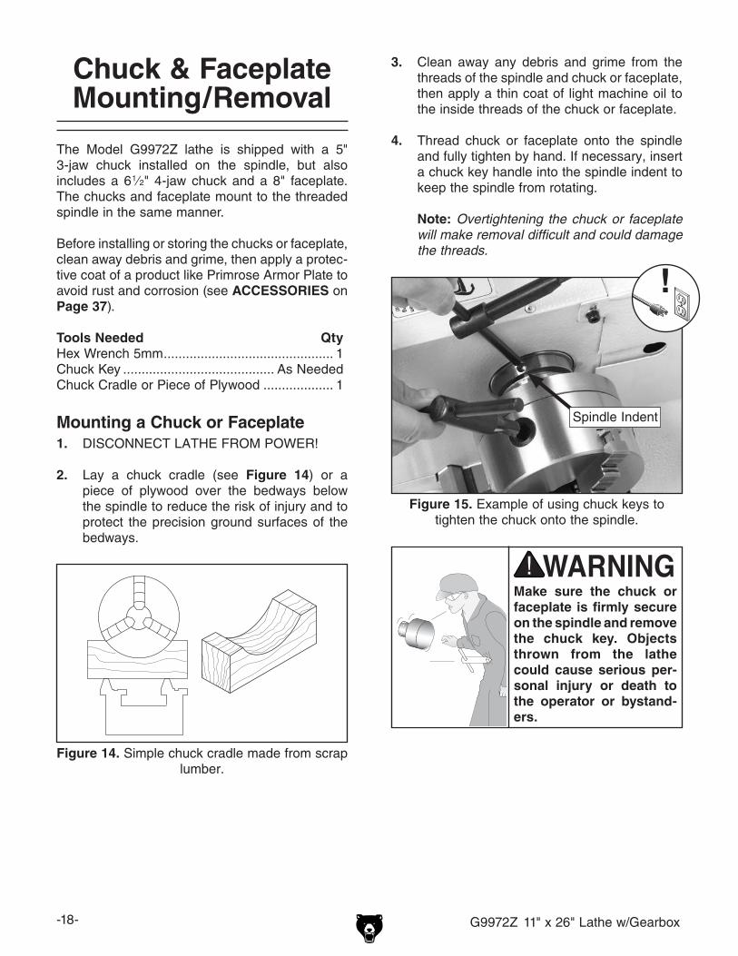
Chuck & Faceplate Mounting/Removal
The Model G9972Z lathe is shipped with a 5" 3-jaw chuck installed on the spindle, but also includes a 6 1⁄2" 4-jaw chuck and a 8" faceplate. The chucks and faceplate mount to the threaded spindle in the same manner.
Before installing or storing the chucks or faceplate, clean away debris and grime, then apply a protec-tive coat of a product like Primrose Armor Plate to avoid rust and corrosion (see ACCESSORIES on Page 37).
Tools Needed QtyHex Wrench 5mm .............................................. 1Chuck Key ......................................... As NeededChuck Cradle or Piece of Plywood ................... 1
Mounting a Chuck or Faceplate1. DISCONNECT LATHE FROM POWER!
2. Lay a chuck cradle (see Figure 14) or a piece of plywood over the bedways below the spindle to reduce the risk of injury and to protect the precision ground surfaces of the bedways.
Figure 14. Simple chuck cradle made from scrap lumber.
Make sure the chuck or faceplate is firmly secure on the spindle and remove the chuck key. Objects thrown from the lathe could cause serious per-sonal injury or death to the operator or bystand-ers.
3. Clean away any debris and grime from the threads of the spindle and chuck or faceplate, then apply a thin coat of light machine oil to the inside threads of the chuck or faceplate.
4. Thread chuck or faceplate onto the spindle and fully tighten by hand. If necessary, insert a chuck key handle into the spindle indent to keep the spindle from rotating.
Note: Overtightening the chuck or faceplate will make removal difficult and could damage the threads.
Figure 15. Example of using chuck keys to tighten the chuck onto the spindle.
Spindle Indent

G9972Z 11" x 26" Lathe w/Gearbox -19-
PINCH HAZARD! Protect your hands and the precision ground bedways with plywood or a chuck cradle when removing the lathe chuck! The heavy weight of a falling chuck can cause serious injury.
6. Remove the chuck cradle or plywood and any tools used before starting the lathe.
5. Position spindle clamps as shown in Figure 16, then tighten the cap screws to secure chuck or faceplate to spindle.
Figure 16. Spindle clamp and cap screw securing chuck/faceplate to spindle.
Spindle Clamp & Cap
Screw
Removing a Chuck or Faceplate1. DISCONNECT LATHE FROM POWER!
2. Lay a chuck cradle (see Figure 14) or a piece of plywood over the bedways below the spindle to reduce the risk of injury and to protect the precision ground surfaces of the bedways.
3. Remove both spindle clamps from behind the chuck or faceplate (see Figure 16).
4. Insert the chuck keys into the spindle indent, as shown in Figure 15, then unthread the chuck or faceplate from the spindle.

-20- G9972Z 11" x 26" Lathe w/Gearbox
3-Jaw Chuck
The 3-jaw chuck included with this lathe is a scrolling-type chuck, which means all three jaws move at the same time when the chuck key is turned.
There is also an external set of jaws included that accommodate additional workpiece configura-tions. Use the correct jaws to hold your workpiece firmly and securely on the chuck (see Figure 17 for examples).
Clamping in an Inside Diameter
Clamping on an Outside Diameter
Figure 17. Examples of using the 3-jaw chuck to hold a workpiece.
Tools Needed Qty3-Jaw Chuck Key .............................................. 1
Mounting Workpiece in 3-Jaw Chuck1. DISCONNECT LATHE FROM POWER!
2. Use the chuck key to open the jaws until the workpiece sits flat against the chuck face, evenly on the jaw steps, or fits into the chuck hole and through the spindle.
3. Close the jaws until they make light contact with the workpiece.
4. Rotate the chuck by hand to make sure all three jaws evenly contact the workpiece and the workpiece is centered.
— If the workpiece is off center, loosen the jaws and adjust the workpiece.
— If the workpiece is centered, fully tighten the jaws.
Securely clamp your workpiece and remove the chuck key! Thrown objects from a lathe can cause serious injury or death to the operator and to bystanders many feet away.
Removing Jaws from 3-Jaw Chuck1. DISCONNECT LATHE FROM POWER!
2. Place a piece of wood below the chuck to protect the bedways.
3. Insert and turn the chuck key counterclock-wise to back the jaws all the way out.
4. Clean the jaw mating surfaces, then apply a thin coat of an anti-rust protective lubricant.
Note: Store the jaws in a place free from moisture and abrasives.
G9972Z 11" x 26" Lathe w/Gearbox -21-
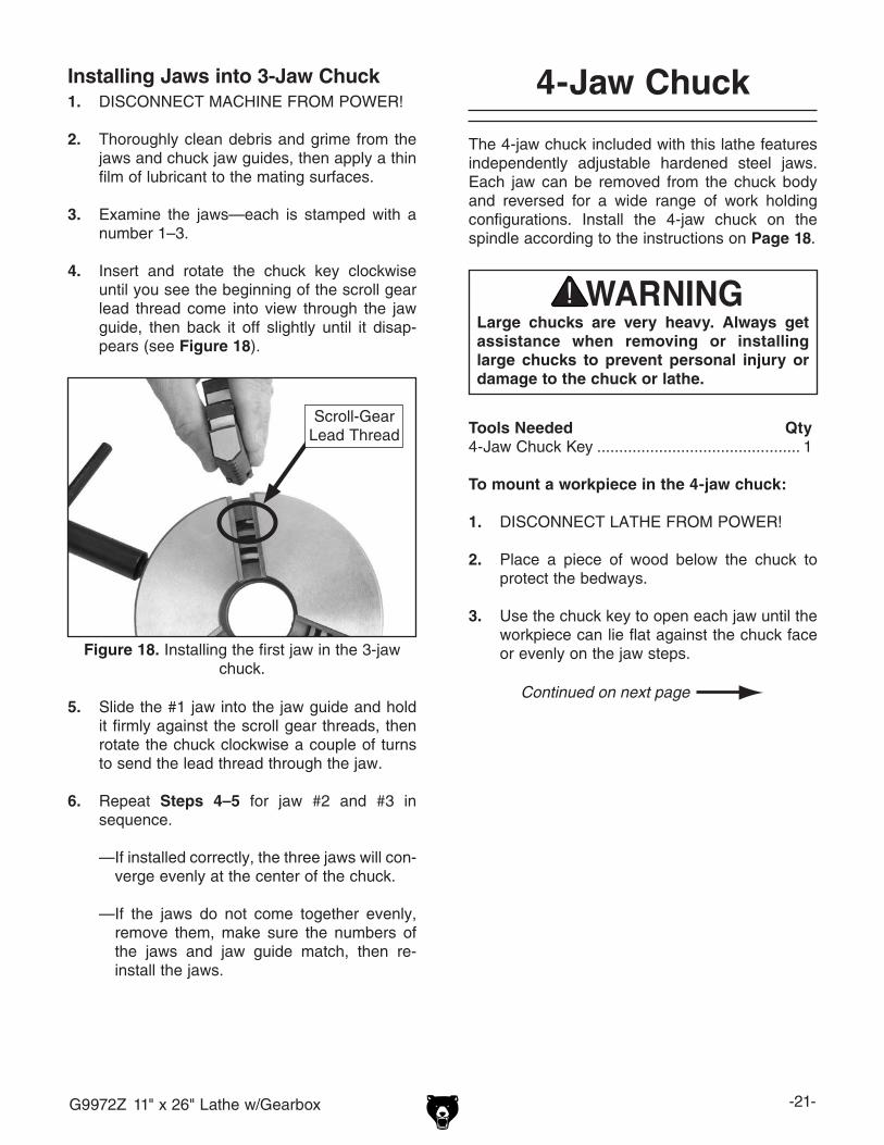
Figure 18. Installing the first jaw in the 3-jaw chuck.
Scroll-Gear Lead Thread
4-Jaw Chuck
The 4-jaw chuck included with this lathe features independently adjustable hardened steel jaws. Each jaw can be removed from the chuck body and reversed for a wide range of work holding configurations. Install the 4-jaw chuck on the spindle according to the instructions on Page 18.
Large chucks are very heavy. Always get assistance when removing or installing large chucks to prevent personal injury or damage to the chuck or lathe.
Tools Needed Qty4-Jaw Chuck Key .............................................. 1
To mount a workpiece in the 4-jaw chuck:
1. DISCONNECT LATHE FROM POWER!
2. Place a piece of wood below the chuck to protect the bedways.
3. Use the chuck key to open each jaw until the workpiece can lie flat against the chuck face or evenly on the jaw steps.
Installing Jaws into 3-Jaw Chuck1. DISCONNECT MACHINE FROM POWER!
2. Thoroughly clean debris and grime from the jaws and chuck jaw guides, then apply a thin film of lubricant to the mating surfaces.
3. Examine the jaws—each is stamped with a number 1–3.
4. Insert and rotate the chuck key clockwise until you see the beginning of the scroll gear lead thread come into view through the jaw guide, then back it off slightly until it disap-pears (see Figure 18).
5. Slide the #1 jaw into the jaw guide and hold it firmly against the scroll gear threads, then rotate the chuck clockwise a couple of turns to send the lead thread through the jaw.
6. Repeat Steps 4–5 for jaw #2 and #3 in sequence.
— If installed correctly, the three jaws will con-verge evenly at the center of the chuck.
— If the jaws do not come together evenly, remove them, make sure the numbers of the jaws and jaw guide match, then re-install the jaws.

-22- G9972Z 11" x 26" Lathe w/Gearbox
4. With assistance to hold the workpiece in place, tighten each jaw in small increments. After adjusting the first jaw, continue tight-ening in opposing sequence, as shown in Figure 19, until the workpiece is firmly secure in the desired position.
1
2
3
4
Figure 19. Tightening sequence for the 4-jaw chuck.
5. Make fine adjustments to the workpiece posi-tion by using a test indicator and adjusting the jaws until the workpiece is precisely aligned (see Figure 20 for an example).
Figure 20. Example of aligning workpiece with a test indicator on a 4-jaw chuck.
Always use a low spindle speed when machining non-cylindrical or off-center workpieces to avoid ejecting the workpiece from the holding device at a high rate of speed. Failure to heed this warning could lead to serious personal injury, death or property damage.
Faceplate
The faceplate can be used for mounting non-cylin-drical parts or for off-center turning by clamping the workpiece to it. Refer to the ACCESSORIES section on Page 38 for clamping options.
To mount a workpiece to the faceplate:
1. DISCONNECT LATHE FROM POWER!
2. Place a piece of wood below the chuck to protect the bedways.
3. With assistance, place the workpiece onto the faceplate and clamp it in place with a min-imum of three independent clamping devices (see Figure 21 for an example).
Note: Take into account the rotation and cutting forces that will be applied to the workpiece when clamping it to the faceplate.
Figure 21. Faceplate with properly mounted workpiece clamped in four locations.

G9972Z 11" x 26" Lathe w/Gearbox -23-
Centers
The Model G9972Z lathe includes an MT#3 dead center for the tailstock quill and an MT#4 dead center for the spindle.
Matching tapers in the spindle and tailstock quill provide the locking action for installing the cen-ters. Before inserting any center or arbor, make sure the mating surfaces are perfectly clean. If oil or grit is present on the mating surfaces, the tapers will not interlock or will be extremely dif-ficult to remove. These parts will last long and remain accurate if properly maintained.
Centers are most often installed in the tailstock quill or used with the faceplate (see Figure 22 for examples).
Figure 22. Centers installed in the tailstock quill and the spindle with a faceplate.
Live centers are typically built with bearings and spin during use, so they do not need lubrication. However, dead centers do not spin during use and require the tip to be constantly lubricated with anti-seize grease.
NOTICETo avoid premature wear of the dead center or damage to the workpiece, always keep the dead center tip well lubricated during use.
Using a Center in the Spindle1. DISCONNECT LATHE FROM POWER!
2. Thoroughly clean the mating surfaces of the center and spindle, then firmly insert the MT#4 dead center into the spindle.
Note: When using the dead center in the spindle, use a lathe dog so that your part will rotate with the spindle.
3. To remove the center from the spindle, insert a piece of round bar stock or similar tool through the outboard end of the spindle (on the left side of the headstock), then tap the center loose.
Note: Hold onto the center as you tap it loose to avoid it dropping it and damaging the tip or the bedways.
Using a Center in the Tailstock1. Feed the tailstock quill out about 1", then
insert the MT#3 dead center into the quill.
2. Position the tailstock so the center presses against the workpiece, then lock the tailstock in place.
3. Feed the quill and dead center into the workpiece, then lock the quill in place.
Note: The force against the mounted workpiece will fully seat the center's taper.
4. To remove the center from the quill, hold on to the center with one hand, then retract the quill back into the tailstock until the center pops free.

-24- G9972Z 11" x 26" Lathe w/Gearbox
Offsetting Tailstock
The tailstock can be offset slightly to cut shallow tapers. When the tailstock is positioned toward the operator and away from the spindle center line, the machined workpiece end will be smaller in diameter at the tailstock end. Conversely, if the tailstock is positioned away from the operator, the taper will be at the spindle end.
Alternately loosen and tighten the two tailstock adjustment set screws until the desired offset is indicated on the offset scale (see Figure 23). To return the tailstock back to the original position, repeat the process until the centered position is indicated on the scale, then perform the Aligning Tailstock instructions.
Aligning Tailstock
The tailstock alignment with the headstock was set at the factory. However, we recommend that you take the time to ensure that the tailstock is aligned to your own desired tolerances.
To align the tailstock:
1. Use a machinist's precision level on the bedways to ensure the lathe is level side-to-side and front-to-back. If the lathe is not level, correct this condition before proceeding (refer to Moving and Placement on Page 12 for detailed instructions).
2. Center drill a 6" long piece of round bar stock on both ends. Set it aside for use in Step 5.
Note: If the tailstock is slightly out of align-ment by a few thousands of an inch, the center drill will find the center point during the drilling process. If the tailstock appears gross-ly out of alignment, move the tailstock until it appears to be centered (refer to the previous subsection for detailed instructions).
3. Make a dead center by turning a shoulder on a similar piece of round bar stock, then flip the piece over in the chuck and turn a 60° point (see Figure 24).
Note: As long as the fabricated dead center remains in the chuck, the point of this center will remain true to the spindle axis or center line. Keep in mind that the point will have to be re-finished whenever it is removed and re-installed in the chuck.
Figure 24. Fabricated dead center.
Figure 23. Tailstock offset adjustments.
Offset ScaleAdjustment Set Screw (1 of 2)

G9972Z 11" x 26" Lathe w/Gearbox -25-
4. Install the MT#3 dead center in the tailstock quill and lubricate the tip.
5. Attach a lathe dog at the spindle end of the bar stock from Step 2, then mount it between the centers (see Figure 25 for an example).
Figure 25. Bar stock mounted between centers.
6. Turn approximately 0.010" off the diameter of the entire length of the workpiece.
7. Mount a dial indicator so that the plunger is on the tailstock barrel.
8. Measure the diameters of both ends of the workpiece.
— If the machined workpiece is thicker at the tailstock end, move the tailstock toward the operator half the distance of the amount of taper (see Figure 26).
Move tailstock in half the distance
of the taper.
Looking down from above.
Figure 26. Tailstock adjustment toward the operator (viewed from above).
— If the machined workpiece is thinner at the tailstock end, move the tailstock away from the operator half the distance of the amount of taper (see Figure 27 ).
Move tailstock in half the distance
of the taper.
Looking down from above.
Figure 27. Tailstock adjustment away from the operator (viewed from above).
9. Refer to Offsetting Tailstock on Page 24 for making adjustments to the tailstock position. Turn another 0.010" off the diameter of the workpiece, then re-check the taper. Repeat this process as necessary until the desired amount of accuracy is achieved.

-26- G9972Z 11" x 26" Lathe w/Gearbox
Drilling with Tailstock
The tailstock can be used to drill holes by mounting a drill bit in the tailstock, rotating the workpiece with the spindle, then using the tailstock quill handwheel to advance the drill bit into the workpiece. See Figures 28–29 for examples of drill chuck and tapered drill bit installation.
Figure 28. Example of drill chuck installation.
Figure 29. Example of drill bit installation.
Steady Rest
The steady rest serves as a support for long, slender workpieces where the length to diameter ratio is 3:1 or greater. The steady rest can be posi-tioned anywhere along the length of the bedway.
Tools Needed QtyWrench 14mm ................................................... 1
To install and use the steady rest:
1. Remove the clamp hex nut, flat washer, and clamp block from the bottom of the steady rest.
2. Clean away any debris and grime from the bedways, the steady rest ways, and the clamp block.
3. Position the steady rest on the bedway so the triangular notch fits over the rear angled bedway rail, as shown in Figure 30, then re-install and tighten the clamp block.
Figure 30. Steady rest controls.
Finger
Lock Nut
Notch
Adjustment Knob
Clamp Hex Nut

G9972Z 11" x 26" Lathe w/Gearbox -27-
4. Loosen the finger lock nuts, turn the adjust-ment knobs to fit the fingers snug to the workpiece, then re-tighten the lock nuts.
Note: The fingers should be snug enough to fully support the workpiece at all three points and also allow free rotational movement of the workpiece.
5. Lubricate the finger tips with an anti-seize grease during operation.
Note: After prolonged use, the fingers will require milling or filing to clean up the contact surface.
Follow Rest
The follow rest shown in Figure 31 is mounted on the front of the saddle and follows the movement of the tool. The follow rest is used on long, slender parts to prevent flexing of the workpiece from the pressure of the cutting tool. This rest requires only two fingers as the cutting tool acts as the third.
Figure 31. Follow rest attachment.
The follow rest can be attached/removed from the carriage by two cap screws located at the base of the follow rest. The sliding fingers are set similar to those of the steady rest—free of play but not binding. Always lubricate the tips with an anti-seize grease before and during operation. Remove the follow rest from the saddle when not in use. After prolonged use, the fingers will require milling or filing to clean up the contact surface.
Cross Slide
Handwheel Dial Increments ResolutionEach Mark ................................................. 0.001"One Revolution ..........................................0.060"
The cross slide sits directly on the saddle and moves perpendicular to the workpiece when the handwheel is rotated (see Figure 32).
Note: The cross slide graduated dial is a 2:1 dial. The amount removed from the workpiece will be twice the actual distance the cross slide moves.
For example, if you wanted to remove 0.20" from the diameter of a workpiece, you would move the cross slide only 0.10".
The metal lathe repre-sents an entanglement hazard from rotating parts. Always tie back long hair, ponytails, loose clothing, and sleeves, and remove all jewelry.
Figure 32. Cross slide handhweel and dial.
Cross Slide Handwheel
& Dial
-28- G9972Z 11" x 26" Lathe w/Gearbox
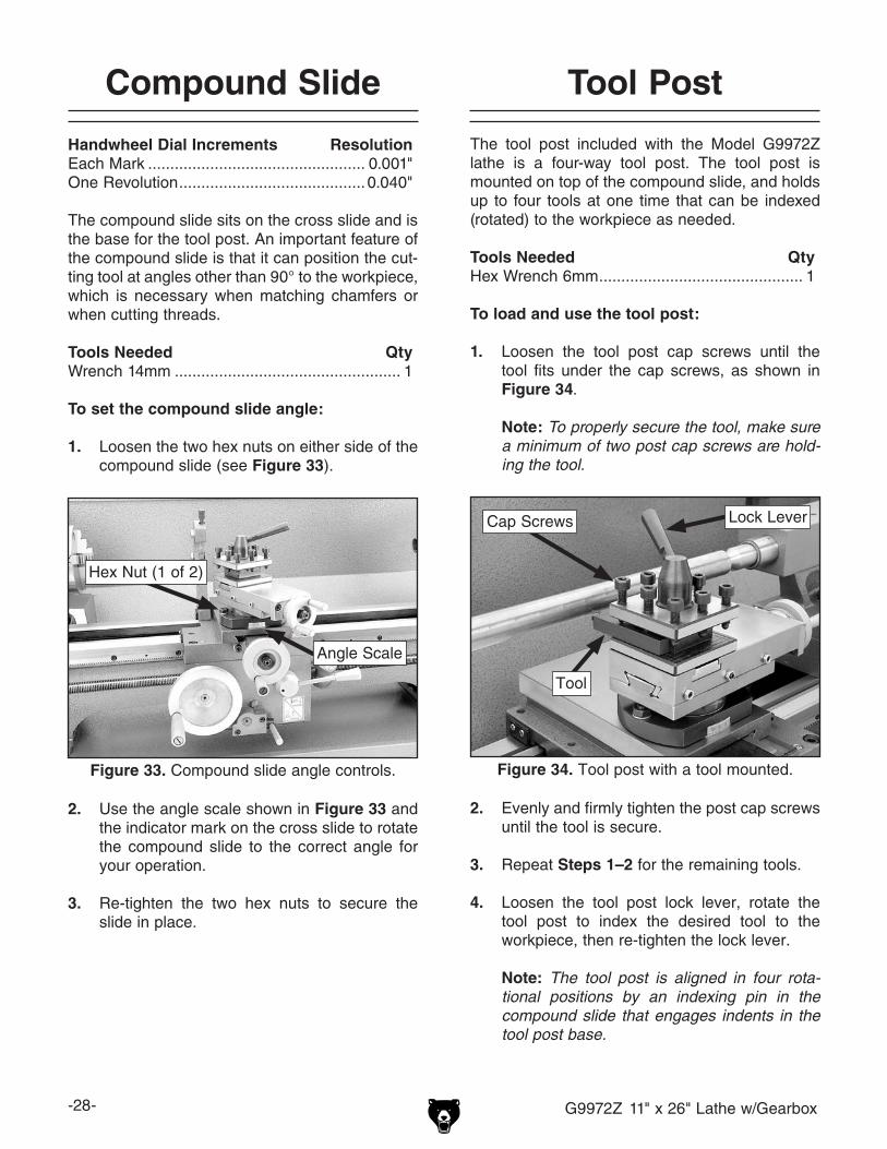
Compound Slide
Handwheel Dial Increments ResolutionEach Mark ................................................. 0.001"One Revolution .......................................... 0.040"
The compound slide sits on the cross slide and is the base for the tool post. An important feature of the compound slide is that it can position the cut-ting tool at angles other than 90° to the workpiece, which is necessary when matching chamfers or when cutting threads.
Tools Needed QtyWrench 14mm ................................................... 1
To set the compound slide angle:
1. Loosen the two hex nuts on either side of the compound slide (see Figure 33).
2. Use the angle scale shown in Figure 33 and the indicator mark on the cross slide to rotate the compound slide to the correct angle for your operation.
3. Re-tighten the two hex nuts to secure the slide in place.
Tool Post
The tool post included with the Model G9972Z lathe is a four-way tool post. The tool post is mounted on top of the compound slide, and holds up to four tools at one time that can be indexed (rotated) to the workpiece as needed.
Tools Needed QtyHex Wrench 6mm .............................................. 1
To load and use the tool post:
1. Loosen the tool post cap screws until the tool fits under the cap screws, as shown in Figure 34.
Note: To properly secure the tool, make sure a minimum of two post cap screws are hold-ing the tool.
2. Evenly and firmly tighten the post cap screws until the tool is secure.
3. Repeat Steps 1–2 for the remaining tools.
4. Loosen the tool post lock lever, rotate the tool post to index the desired tool to the workpiece, then re-tighten the lock lever.
Note: The tool post is aligned in four rota-tional positions by an indexing pin in the compound slide that engages indents in the tool post base.
Figure 33. Compound slide angle controls.
Angle Scale
Hex Nut (1 of 2)
Figure 34. Tool post with a tool mounted.
Tool
Lock LeverCap Screws

G9972Z 11" x 26" Lathe w/Gearbox -29-
Spindle Speed
To set the correct spindle speed for your opera-tion, you will need to: 1) Determine the spindle speed (RPM) needed for your workpiece mate-rial, and 2) configure the V-belt for the calculated spindle speed.
Calculating the Correct Spindle RPM1. Use the table in Figure 35 to determine the
recommended cutting speed for the workpiece material.
Note: Cutting speeds are expressed in sur-face feet per minute (SFM) that the cutter moves against the workpiece.
Recommended Cutting Speeds
Work MaterialMagnesiumAluminumBrass & BronzeCopperCast Iron (Soft)Cast Iron (Hard)Mild SteelCast Steel
Tool SteelAlloy Steels (Hard)
Stainless SteelTitaniumHi Maganese Steel
Average Tool Speed (sfm)Rough Cuts Finish Cuts
40035025010010050100705050609040
800700500250250150250150150150180200100
Note: These values are based on HSS cutting tools. For carbide cutting tools, double the aver-age speed. These values are a guideline only. Refer to the MACHINERY’S HANDBOOK for more detailed information.
Figure 35. Recommend cutting speed table.
2. Determine the final diameter, in inches, for the cut you intend to make.
Note: For this step, you will need to aver-age out the diameters or work with the finish diameter.
3. Use the following formula to determine the correct spindle speed (RPM) for your opera-tion:Cutting Speed (FPM) x 12
*Recommended
Dia. of Cut (in inches) x 3.14
SpindleSpeed(RPM)
*Double if using carbide cutting tool
=
Example A You will finish cut 1⁄2" diameter piece of
cast steel stock, using an HSS cutting tool.
Step 1: 150 (SFM from chart) x 4 = 600
Step 2: 600 / .5" (Diameter of workpiece) = 1200
Result: The correct spindle speed is 1200 RPM.
Example B You will rough turn a 1" diameter piece
of stainless steel, using a carbide cutting tool.
Step 1: 60 (SFM from chart) x 2 (for carbide tool)
= 120
Step 2: 120 (Determined SFM) x 4 = 480
Step 3: 480 / 1" (Diameter of workpiece) = 480
RPM
Result: The correct spindle speed is 480 RPM.
-30- G9972Z 11" x 26" Lathe w/Gearbox
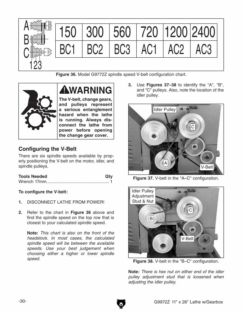
3. Use Figures 37–38 to identify the "A", "B", and "C" pulleys. Also, note the location of the idler pulley.
150 300 560 720 1200 2400BC1 BC2 BC3 AC1 AC2 AC3
ABC123
Figure 36. Model G9772Z spindle speed V-belt configuration chart.
Configuring the V-BeltThere are six spindle speeds available by prop-erly positioning the V-belt on the motor, idler, and spindle pulleys.
Tools Needed QtyWrench 17mm.................................................... 1
To configure the V-belt:
1. DISCONNECT LATHE FROM POWER!
2. Refer to the chart in Figure 36 above and find the spindle speed on the top row that is closest to your calculated spindle speed.
Note: This chart is also on the front of the headstock. In most cases, the calculated spindle speed will be between the available speeds. Use your best judgement when choosing either a higher or lower spindle speed.
The V-belt, change gears, and pulleys represent a serious entanglement hazard when the lathe is running. Always dis-connect the lathe from power before opening the change gear cover.
Note: There is hex nut on either end of the idler pulley adjustment stud that is loosened when adjusting the idler pulley.
Figure 37. V-belt in the "A–C" configuration.
A
C
Idler Pulley
V-Belt
Figure 38. V-belt in the "B–C" configuration.
B
C
V-Belt
Idler Pulley Adjustment Stud & Nut

G9972Z 11" x 26" Lathe w/Gearbox -31-
4. Configure the V-belt on the pulleys according to the letter and number combination under the selected spindle speed from the chart in Figure 36.
Position the idler pulley on top of the V-belt with enough downward pressure to provide tension to the belt, then fully secure it in place. There is correct tension to the V-belt when there is approximately 1⁄2" deflection when moderate pressure is applied to the V-belt half-way between the pulleys.
Note: The pulley slots are numbered 1–3 with number 1 being the outside slot.
— For "A–C" configurations (see Figure 37), position the longer V-belt (32" in circumfer-ence) in the correct "C" pulley slot, then roll it onto the "A" pulley.
—For "B–C" configurations (see Figure 38), place the shorter V-belt (29" in circumfer-ence) in the correct "C" pulley slot, then roll it onto the "B" pulley.
Power Feed
"Power Feed" on a lathe simply means using the machine-driven components to feed the tool into the workpiece rather than feeding it manually with handwheels.
The speed at which the carriage travels is set with the feed rate dials (see Feed Rate on Page 32 for detailed instructions), but it also depends on spindle speed.
NOTICEFeed rate is based on the spindle speed. High feed rates result in a rapidly moving carriage. Pay close attention to the feed rate you have chosen and keep your hand poised over the power feed lever. Failure to fully understand this could cause the car-riage to crash into the spindle or tailstock resulting in severe damage to the lathe.
When the proper feed rate has been selected for the operation, simply move the power feed lever up to engage the carriage with the power feed (see Figure 39). Move the lever down to disen-gage the power feed.
When the spindle is rotating counterclockwise (towards the operator), the carriage will move toward the spindle when engaged with the power feed. Conversely, when the spindle is rotating clockwise (away from the operator), the carriage will move toward the tailstock.
Note: If the spindle is not turning, you may have to manually jog the carriage to engage the apron gearing with the leadscrew.
NOTICENEVER attempt to engage the carriage power feed (lever up) and the half-nut (lever down) at the same time. Always disengage the half-nut (lever up) before moving the power feed lever up. Otherwise, severe damage to the lathe could occur.
Figure 39. Power feed lever engaged and disengaged.
Disengaged (Off)
Engaged (On)

-32- G9972Z 11" x 26" Lathe w/Gearbox
Feed Rate
Feed rate is the speed the tool travels during the operation and is expressed in inches of carriage travel per revolution of the spindle (IPR), and is set by configuring the change gears and feed rate dials.
The correct feed rate is determined by the workpiece material, the type of tooling used, and the desired finish. The table in Figure 40 shows the recommended feed rate for turning most met-als.
Recommended Feed Rates
Work MaterialMagnesiumAluminumBrass & BronzeCopperCast Iron (Soft)Cast Iron (Hard)Mild SteelCast Steel
Tool SteelAlloy Steels (Hard)
Stainless SteelTitaniumHi Maganese Steel
Tool Feed Rate (IPR)Rough Cuts Finish Cuts0.015–0.0250.015–0.0250.015–0.0250.010–0.0200.015–0.0250.010–0.0200.010–0.0200.010–0.0200.010–0.0200.010–0.0200.010–0.0200.010–0.0200.010–0.020
0.005–0.0100.005–0.0100.003–0.0100.004–0.0080.005–0.0100.003–0.0100.003–0.0100.003–0.0100.003–0.0100.003–0.0100.003–0.0100.003–0.0100.003–0.010
Note: These values are a guideline only. Refer to the MACHINERY’S HANDBOOK for more detailed information.
Figure 40. Recommended feed rate table.
ba lever C A B24282835
84707770
IIII
III
0.00220.00300.00330.0038
0.00450.00600.00670.0077
0.00900.01200.01350.0150b
a120 127
4545 ins/
Figure 42. Feed rate chart for power feed movement of the carriage.
The V-belt, change gears, and pulleys represent a serious entanglement hazard when the lathe is running. Always dis-connect the lathe from power before opening the change gear cover.
Use Figure 41 to identify the change gears and their positions.
Note: This lathe is shipped with the 24 tooth gear installed in the "a" position, and the 84 tooth gear in the "b" position.
Figure 41. Change gears.
Change Gear "b"
Pivot Arm & Cap Screw
Change Gear 120/127T
Change Gear "a"

G9972Z 11" x 26" Lathe w/Gearbox -33-
Tools Needed QtyHex Wrench 5mm .............................................. 1Hex Wrench 6mm .............................................. 1Wrench 10mm ................................................... 1Wrench 14mm ................................................... 1Retaining Clip Wrench ....................................... 1NLGI #2 Grease ................................ As Needed
Configuring Change Gears1. DISCONNECT LATHE FROM POWER!
2. Examine the chart in Figure 42 or Figure 45 to determine the change gear configuration for the selected feed rate.
Note: The feed rates are given in inches of carriage travel per revolution of the spindle (IPR).
3. Open the change gear cover, then arrange the change gears as needed. Leave approxi-mately 0.002"–0.003" (0.05–0.08mm) back-lash between the gears.
Note: Before you install the gears, thoroughly clean them with a stiff brush and mild solvent, then apply a light coat of NLGI #2 grease to the teeth.
Change Gear "a"a. Loosen the cap screw securing the pivot
arm, then lower it to disengage the 120/127T gear from change gear "a" (see Figure 43).
b. Remove the E-clip that secures change gear "a", replace the gear with correct one, then replace the E-clip.
c. Raise the pivot arm so that the 120/127T gear properly meshes with change gear "a", then re-tighten the cap screw to secure it in place.
Change Gear "b"a. Lower the pivot arm as described above.
b. Loosen the square nut on the 120/127T gear and slide it along the pivot arm and away from change gear "b".
c. Loosen and remove the cap screw secur-ing change gear "b", then remove the flat washer, bushing, and the gear.
d. Install the correct change gear "b", the bushing, flat washer, and cap screw.
Note: If change gear "b" must mesh with the 120T gear when cutting metric threads, mount the bushing between the gear and the headstock to properly align the gear.
e. Slide the 120/127T gear over to properly mesh with change gear "b", then re-tight-en the square nut.
f. Raise the pivot arm and secure it in place as described above.
4. Rotate the spindle by hand and make sure all change gears are properly meshed and rotat-ing.
— If the change gears are not properly meshed or rotating freely, repeat this procedure until they are.
5. Close and secure the change gear cover.
Setting the Feed Rate Dials1. Make sure the spindle motor is OFF and the
spindle has come to a complete stop.
2. Examine the chart in Figure 42 or Figure 45, then correctly set feed rate dials for your selected feed rate.
Figure 43. Change gear pivot arm in lowered position.
Change Gear 120/127T
Change Gear "a"
Change Gear "b"

-34- G9972Z 11" x 26" Lathe w/Gearbox
NOTICENEVER move the feed rate dials while the lathe is running, and NEVER force the dials when shifting. If the dial will not engage, rotate the spindle by hand while keeping light pressure on the dial. As the spindle rotates, the feed rate gears will align and the dial will slip into position.
Example of Setting Feed RateYou will rough cut the length of an aluminum workpiece, reducing the diameter.
Step 1:Examine the recommended feed rate table (Figure 40 on Page 32) to find the feed rate should be 0.015–0.025 IPR.
Step 2:Select the nearest feed rate from the feed rate chart (Figure 42 on Page 32) for the lathe. In this case, it will be 0.0150 IPR.
Figure 44. Feed rate dials.
Step 3:Install the 35T change gear in position "a" and the 70T change gear in position "b".
Step 4:Turn the left feed rate dial to "II" and the right dial to "B" (see Figure 44).
Note: It may be necessary to jog the spindle by hand to mesh the feed rate gearing and complete the setting of the dials.
ba lever B A C35
II
I28282824282424
7063707769847884
IIIIIII
I
IIII
ba lever BAC28353535
707070
84
891011111/2121314
1618202223242628
3236404446485256
0.50 1.00 2.001.25 2.50
0.75 1.50 3.001.75 3.50
b
a120 127
4545
b
a120 127
4545
n/1"
mm
Figure 45. Feed rate chart for threading.

G9972Z 11" x 26" Lathe w/Gearbox -35-
Threading Controls
The purpose of this subsection is to orient you with the controls used when threading and how to use the threading dial on this machine.
Power Feed LeverThe power feed lever must be in the disengaged position (down and horizontal) for threading oper-ations or the half-nut will not engage with the leadscrew (see Figure 46).
Half-Nut LeverThe half-nut lever engages the carriage with the leadscrew which moves the tool along the workpiece (see Figure 47).
Thread Dial & ChartThe numbers on the thread dial are used with the thread dial chart (Figure 49 on Page 36) to show when to engage/disengage the half-nut during inch threading operations.
The thread dial must be engaged with the leadscrew to operate. To engage the thread dial, loosen the mounting cap screw, pivot the thread dial gear onto the leadscrew so the gear teeth mesh with the leadscrew, then re-tighten the cap screw (see Figure 48).
NOTICENEVER attempt to engage the carriage power feed (lever up) and the half-nut (lever down) at the same time, and NEVER force these levers. Always disengage the power feed (lever down) before engaging the half-nut. Otherwise, severe damage to the lathe could occur.
Figure 47. Half-nut lever engaged/disengaged.
Disengaged (Off)
Engaged (On)
Figure 48. Thread dial.
Cap Screw
Thread Dial
Thread Dial Gear
Figure 46. Power feed lever disengaged.
Disengaged
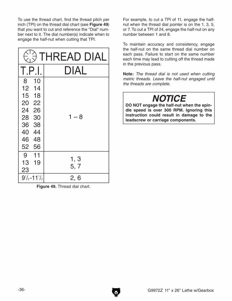
-36- G9972Z 11" x 26" Lathe w/Gearbox
NOTICEDO NOT engage the half-nut when the spin-dle speed is over 300 RPM. Ignoring this instruction could result in damage to the leadscrew or carriage components.
To use the thread chart, find the thread pitch per inch (TPI) on the thread dial chart (see Figure 49) that you want to cut and reference the "Dial" num-ber next to it. The dial number(s) indicate when to engage the half-nut when cutting that TPI.
81215202428364046529132391/2 -111/2
101418222630384448561119
THREAD DIALDIALT.P.I.
1 – 8
1, 35, 7
2, 6Figure 49. Thread dial chart.
For example, to cut a TPI of 11, engage the half-nut when the thread dial pointer is on the 1, 3, 5, or 7. To cut a TPI of 24, engage the half-nut on any number between 1 and 8.
To maintain accuracy and consistency, engage the half-nut on the same thread dial number on each pass. Failure to start on the same number each time may lead to cutting off the thread made in the previous pass.
Note: The thread dial is not used when cutting metric threads. Leave the half-nut engaged until the threads are complete.
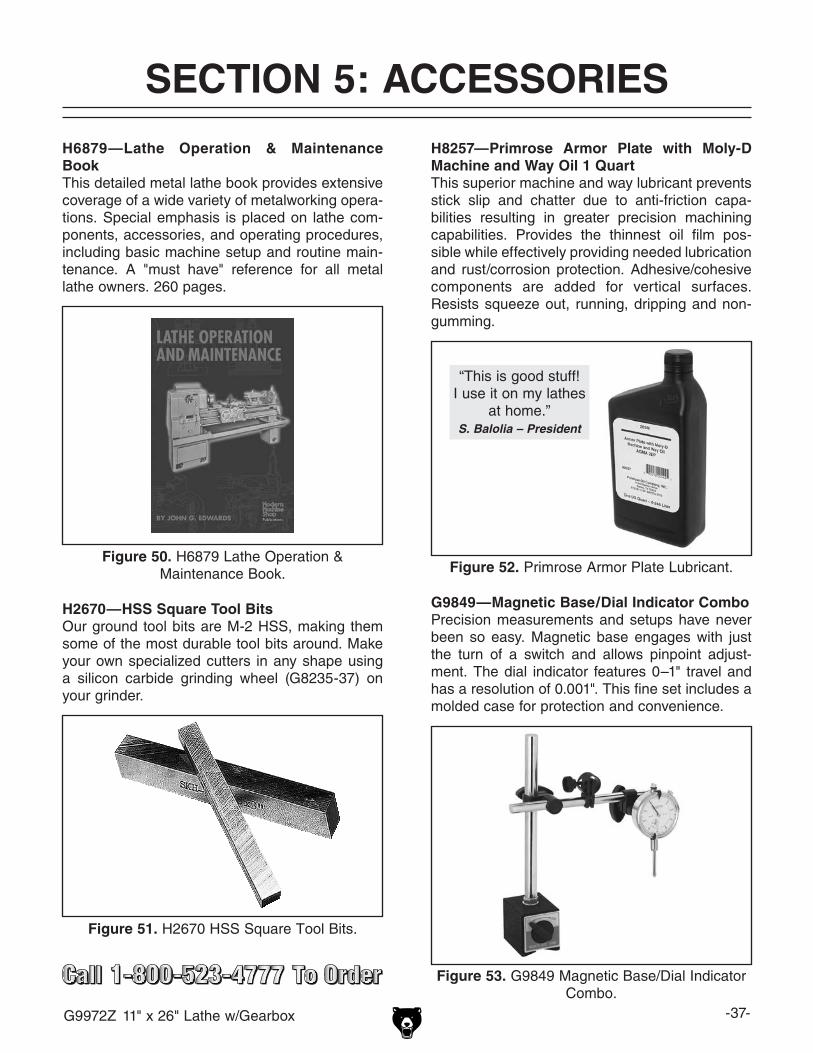
G9972Z 11" x 26" Lathe w/Gearbox -37-
SECTION 5: ACCESSORIESACCESSORIES
H6879—Lathe Operation & Maintenance BookThis detailed metal lathe book provides extensive coverage of a wide variety of metalworking opera-tions. Special emphasis is placed on lathe com-ponents, accessories, and operating procedures, including basic machine setup and routine main-tenance. A "must have" reference for all metal lathe owners. 260 pages.
Figure 50. H6879 Lathe Operation & Maintenance Book.
H8257—Primrose Armor Plate with Moly-D Machine and Way Oil 1 QuartThis superior machine and way lubricant prevents stick slip and chatter due to anti-friction capa-bilities resulting in greater precision machining capabilities. Provides the thinnest oil film pos-sible while effectively providing needed lubrication and rust/corrosion protection. Adhesive/cohesive components are added for vertical surfaces. Resists squeeze out, running, dripping and non-gumming.
Figure 52. Primrose Armor Plate Lubricant.
“This is good stuff!I use it on my lathes
at home.”S. Balolia – President
G9849—Magnetic Base/Dial Indicator ComboPrecision measurements and setups have never been so easy. Magnetic base engages with just the turn of a switch and allows pinpoint adjust-ment. The dial indicator features 0–1" travel and has a resolution of 0.001". This fine set includes a molded case for protection and convenience.
Figure 53. G9849 Magnetic Base/Dial Indicator Combo.
Figure 51. H2670 HSS Square Tool Bits.
H2670—HSS Square Tool BitsOur ground tool bits are M-2 HSS, making them some of the most durable tool bits around. Make your own specialized cutters in any shape using a silicon carbide grinding wheel (G8235-37) on your grinder.
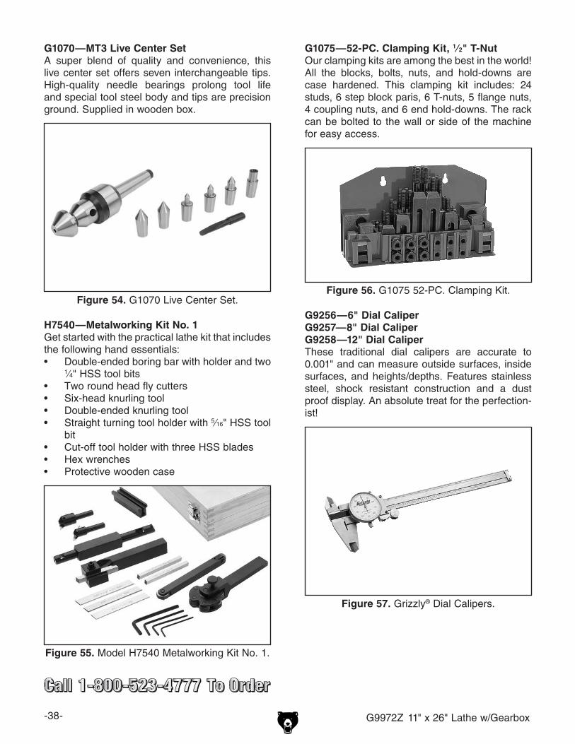
-38- G9972Z 11" x 26" Lathe w/Gearbox
Figure 54. G1070 Live Center Set.
G1070—MT3 Live Center SetA super blend of quality and convenience, this live center set offers seven interchangeable tips. High-quality needle bearings prolong tool life and special tool steel body and tips are precision ground. Supplied in wooden box.
H7540—Metalworking Kit No. 1Get started with the practical lathe kit that includes the following hand essentials:• Double-ended boring bar with holder and two
1⁄4" HSS tool bits• Two round head fly cutters• Six-head knurling tool• Double-ended knurling tool• Straight turning tool holder with 5⁄16" HSS tool
bit• Cut-off tool holder with three HSS blades• Hex wrenches• Protective wooden case
Figure 55. Model H7540 Metalworking Kit No. 1.
G1075—52-PC. Clamping Kit, 1⁄2" T-NutOur clamping kits are among the best in the world! All the blocks, bolts, nuts, and hold-downs are case hardened. This clamping kit includes: 24 studs, 6 step block paris, 6 T-nuts, 5 flange nuts, 4 coupling nuts, and 6 end hold-downs. The rack can be bolted to the wall or side of the machine for easy access.
Figure 56. G1075 52-PC. Clamping Kit.
G9256—6" Dial CaliperG9257—8" Dial CaliperG9258—12" Dial CaliperThese traditional dial calipers are accurate to 0.001" and can measure outside surfaces, inside surfaces, and heights/depths. Features stainless steel, shock resistant construction and a dust proof display. An absolute treat for the perfection-ist!
Figure 57. Grizzly® Dial Calipers.

G9972Z 11" x 26" Lathe w/Gearbox -39-
Figure 58. H2972 Cut Off Holder with Blade.
H2972—Cut Off Holder with BladeH4268—3⁄32" x 5⁄8" x 5" Replacement BladeSmall enough to fit most 4-way turret tool posts, but rugged enough to handle the job, this cut-off tool holder is a must. Comes with a wrench and cut-off tool bit. Uses 3⁄32" x 5⁄8" x 5" tool bits. Shank measures ½" x ¼" x 3".
Figure 59. H2996 Double Ended Boring Bar.
H2996—Double Ended Boring BarThis is a well made boring bar and holder. The boring bar holds the tool bit at 90˚ at one end and 45˚ at the other. Comes with a wrench and tool bit. Bar size is 3⁄8" x 4½", holder is 2¼" x ½", uses 1⁄8" tool bits.
Figure 60. H5936 2 Pc. Knurling Tool Set.
H5936—2 Pc. Knurling Tool SetThis 2 piece set includes a ½" x 4" Single Knurling Tool Holder and a ½" x 4½" Double Knurling Tool Holder with Pivoting Head. Both have a black oxide finish.
Figure 61. H2987-91 Lathe Dogs.
H2987—½" Bent Lathe DogJust the thing for precision machining between centers! These bent tail Lathe Dogs are made of durable cast iron and feature square head bolts.

-40- G9972Z 11" x 26" Lathe w/Gearbox
SECTION 6: MAINTENANCE
Always disconnect power to the machine before performing maintenance. Failure to do this may result in serious person-al injury.
For optimum performance from your machine, follow this maintenance schedule and refer to any specific instructions given in this section.
Daily Check:• Loose mounting bolts.• Damaged or worn belts.• Worn or damaged wires.• Any other unsafe condition.
Every 6–8 Hours of Operation:• Clean lathe.• Lubricate lathe (Pages 41–44).
After First Three Months and Annually:• Change feed rate gearbox oil (Page 42).
Schedule
• Disconnect the lathe from power before cleaning.
• Vacuum excess metal chips as they accumu-late and wipe off built-up grime.
Cleaning & Protecting
DO NOT use compressed air to blow away chips from the lathe to avoid the risk of flying metal debris injuring yourself or oth-ers, or driving the chips deep into the lathe mechanisms resulting in damage or prema-ture wear.
• Use a dry cloth to wipe off any remaining coolant at the end of the day. Metal chips soaked with water-based coolant left on the machine will invite oxidation and gummy resi-due to build up around moving parts.
• Follow Federal, State, and the manufacturer's requirements to properly dispose of used coolant and cleaning products
• Protect the unpainted metal surfaces on the lathe by wiping them clean at the end of oper-ations. Keep these surfaces, especially the bedways, rust-free and working smoothly with regular applications of products like Model H8257 Primrose Armor Plate with Moly-D Machine and Way Oil (see ACCESSORIES on Page 37).
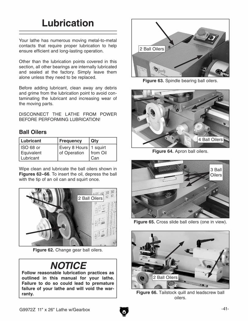
G9972Z 11" x 26" Lathe w/Gearbox -41-
Lubrication
Your lathe has numerous moving metal-to-metal contacts that require proper lubrication to help ensure efficient and long-lasting operation.
Other than the lubrication points covered in this section, all other bearings are internally lubricated and sealed at the factory. Simply leave them alone unless they need to be replaced.
Before adding lubricant, clean away any debris and grime from the lubrication point to avoid con-taminating the lubricant and increasing wear of the moving parts.
DISCONNECT THE LATHE FROM POWER BEFORE PERFORMING LUBRICATION!
Ball OilersLubricant Frequency Qty
ISO 68 or EquivalentLubricant
Every 8 Hoursof Operation
1 squirt from Oil Can
Wipe clean and lubricate the ball oilers shown in Figures 62–66. To insert the oil, depress the ball with the tip of an oil can and squirt once.
Figure 66. Tailstock quill and leadscrew ball oilers.
2 Ball Oilers
NOTICEFollow reasonable lubrication practices as outlined in this manual for your lathe. Failure to do so could lead to premature failure of your lathe and will void the war-ranty.
Figure 62. Change gear ball oilers.
2 Ball Oilers
Figure 63. Spindle bearing ball oilers.
2 Ball Oilers
Figure 64. Apron ball oilers.
4 Ball Oilers
Figure 65. Cross slide ball oilers (one in view).
3 Ball Oilers
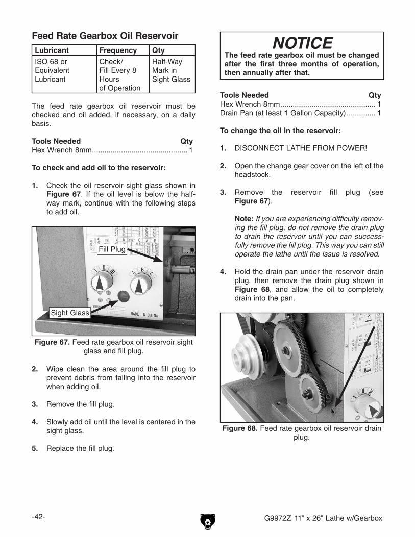
-42- G9972Z 11" x 26" Lathe w/Gearbox
Feed Rate Gearbox Oil ReservoirLubricant Frequency Qty
ISO 68 or EquivalentLubricant
Check/Fill Every 8 Hoursof Operation
Half-Way Mark in Sight Glass
The feed rate gearbox oil reservoir must be checked and oil added, if necessary, on a daily basis.
Tools Needed QtyHex Wrench 8mm .............................................. 1
To check and add oil to the reservoir:
1. Check the oil reservoir sight glass shown in Figure 67. If the oil level is below the half-way mark, continue with the following steps to add oil.
2. Wipe clean the area around the fill plug to prevent debris from falling into the reservoir when adding oil.
3. Remove the fill plug.
4. Slowly add oil until the level is centered in the sight glass.
5. Replace the fill plug.
Tools Needed QtyHex Wrench 8mm .............................................. 1Drain Pan (at least 1 Gallon Capacity) .............. 1
To change the oil in the reservoir:
1. DISCONNECT LATHE FROM POWER!
2. Open the change gear cover on the left of the headstock.
3. Remove the reservoir fill plug (see Figure 67).
Note: If you are experiencing difficulty remov-ing the fill plug, do not remove the drain plug to drain the reservoir until you can success-fully remove the fill plug. This way you can still operate the lathe until the issue is resolved.
4. Hold the drain pan under the reservoir drain plug, then remove the drain plug shown in Figure 68, and allow the oil to completely drain into the pan.
NOTICEThe feed rate gearbox oil must be changed after the first three months of operation, then annually after that.
Figure 67. Feed rate gearbox oil reservoir sight glass and fill plug.
Sight Glass
Fill Plug
Figure 68. Feed rate gearbox oil reservoir drain plug.

G9972Z 11" x 26" Lathe w/Gearbox -43-
Compound SlideLubricant Frequency Qty
Way Oil Every 8 Hoursof Operation
Thin Coat
Maintain a thin coat of way oil on the slide surface of the compound slide. Use the handwheel to move the compound slide all the way toward you (see Figure 70), then wipe clean the bottom slide with a rag and mild solvent. Apply the lubricant and move the compound slide back and forth to distribute the oil.
5. While holding the pan under the drain hole, pour approximately 1⁄2 quart of clean oil into the reservoir to flush out any sediment from along the bottom.
6. Re-install the drain plug and add oil to the reservoir until the oil level is centered in the sight glass.
7. Re-install the fill plug and close the change gear cover.
Longitudinal Leadscrew & Carriage RackLubricant Frequency Qty
ISO 68 or EquivalentLubricant
Every 8 Hoursof Operation
Thin Coat
Maintain a thin coat of oil on the longitudinal leadscrew threads and the carriage rack (see Figure 69) at all times. Use a stiff brush and mild solvent to remove any debris or grime before using a clean shop rag to wipe on the oil.
Figure 69. Longitudinal leadscrew and carriage rack.
Leadscrew
Rack
Figure 70. Compound bottom slide.
Bottom Slide
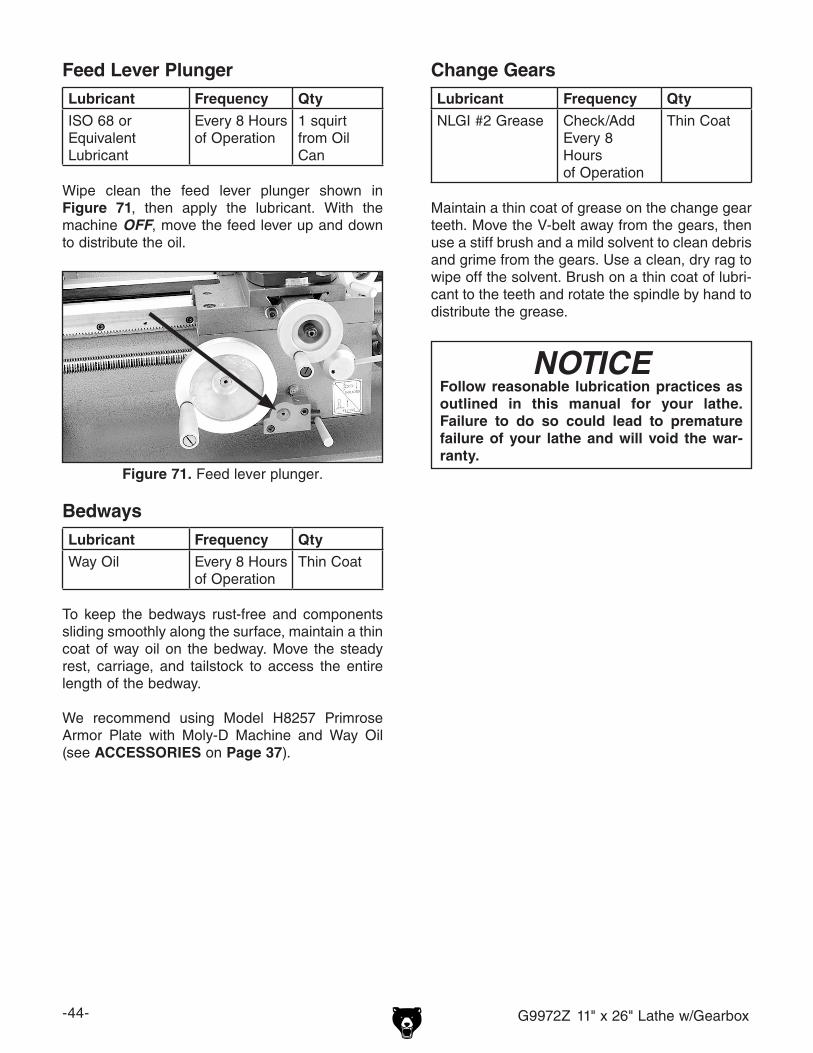
-44- G9972Z 11" x 26" Lathe w/Gearbox
BedwaysLubricant Frequency Qty
Way Oil Every 8 Hoursof Operation
Thin Coat
To keep the bedways rust-free and components sliding smoothly along the surface, maintain a thin coat of way oil on the bedway. Move the steady rest, carriage, and tailstock to access the entire length of the bedway.
We recommend using Model H8257 Primrose Armor Plate with Moly-D Machine and Way Oil (see ACCESSORIES on Page 37).
Feed Lever PlungerLubricant Frequency Qty
ISO 68 or EquivalentLubricant
Every 8 Hoursof Operation
1 squirt from Oil Can
Wipe clean the feed lever plunger shown in Figure 71, then apply the lubricant. With the machine OFF, move the feed lever up and down to distribute the oil.
Change GearsLubricant Frequency Qty
NLGI #2 Grease Check/Add Every 8 Hoursof Operation
Thin Coat
Maintain a thin coat of grease on the change gear teeth. Move the V-belt away from the gears, then use a stiff brush and a mild solvent to clean debris and grime from the gears. Use a clean, dry rag to wipe off the solvent. Brush on a thin coat of lubri-cant to the teeth and rotate the spindle by hand to distribute the grease.
NOTICEFollow reasonable lubrication practices as outlined in this manual for your lathe. Failure to do so could lead to premature failure of your lathe and will void the war-ranty.
Figure 71. Feed lever plunger.
G9972Z 11" x 26" Lathe w/Gearbox -45-
Review the troubleshooting and procedures in this section to fix or adjust your machine if a problem devel-ops. If you need replacement parts or you are unsure of your repair skills, then feel free to call our Technical Support at (570) 546-9663.
SECTION 7: SERVICE
Troubleshooting
Motor & Electrical
Symptom Possible Cause Possible SolutionMachine does not start or a breaker trips.
1. Plug or receptacle is at fault or wired incorrectly.
2. Start capacitor is at fault.3. Wall fuse or circuit breaker is blown or
tripped.4. Motor connection is wired incorrectly.5. Power supply is at fault, or is switched
OFF.6. Motor ON/OFF button is at fault.7. Centrifugal switch is at fault.8. Spindle switch is at fault.9. Cable or wiring is open or has high
resistance.
10. Motor is at fault.
1. Test power plug and receptacle for good contact and correct wiring.
2. Test capacitor and replace if necessary.3. Make sure circuit breaker/fuse is sized correctly for
machine load; replace faulty breaker.4. Correct motor wiring (Page 55).5. Make sure all hot lines and grounds are operational
and have correct voltage.6. Replace faulty motor ON/OFF button.7. Adjust/replace.8. Test; replace if necessary.9. Troubleshoot wires for internal/external breaks;
check for disconnected or corroded connections; repair or replace faulty wiring or connections.
10. Test/repair/replace.
Machine has vibration or noisy operation.
1. Motor or component is loose.
2. V-belt worn, damaged, or loose.3. Motor fan is rubbing on fan cover.4. Pulley set screws or keys are missing or
loose.5. Machine is incorrectly mounted.
6. Cutting tool is chattering.
7. Workpiece or chuck is at fault.
8. Spindle bearings are at fault.9. Motor bearings are at fault.
10. Gears are at fault.
1. Inspect/replace stripped or damaged fasteners; re-tighten with thread locking fluid.
2. Replace/re-tension V-belt (Page 30).3. Repair/replace dented fan cover or fan.4. Inspect set screws/keys; replace/tighten if
necessary.5. Re-tighten/replace machine mounting hardware as
necessary; use shims where required.6. Re-sharpen/replace cutting tool; index tool to
workpiece; use correct feed rate and spindle speed.7. Re-center and properly secure workpiece in chuck or
faceplate; replace defective chuck/faceplate.8. Tighten/replace spindle bearings (Page 51).9. Rotate motor shaft to check for noisy or burnt
bearing; repair/replace as necessary.10. Replace bad gears/bearings.

-46- G9972Z 11" x 26" Lathe w/Gearbox
Motor & Electrical (continued)
Symptom Possible Cause Possible SolutionMachine stalls or is overloaded.
1. Wrong workpiece material.
2. Workpiece alignment is at fault.
3. Incorrect spindle speed for task.4. Low power supply.
5. Run capacitor is at fault.6. V-belt is slipping.
7. Plug or receptacle is at fault.
8. Motor connection is wired incorrectly.9. Motor bearings are at fault.
10. Machine is undersized for the task.
11. Motor has overheated.
12. Spindle switch is at fault.13. Motor is at fault.14. Centrifugal switch is at fault.
1. Only process metal that has the correct properties for your type of machining.
2. Re-center and properly secure workpiece in chuck or faceplate.
3. Correctly set V-belt for your operation (Page 29).4. Make sure all hot lines and grounds are operational
and have correct voltage.5. Test and replace if necessary.6. Check V-belt and re-tension; replace if necessary
(Page 30).7. Test power plug and receptacle for good contact and
correct wiring.8. Correct motor wiring (Page 55).9. Rotate motor shaft to check for noisy or burnt
bearing; repair/replace as necessary.10. Use sharp cutting tools at the correct angle, reduce
feed rate or depth of cut, and use coolant if possible.
11. Clear obstacles away from the motor fan cover, let motor cool, and reduce workload on machine.
12. Test; replace if necessary.13. Test/repair/replace.14. Adjust/replace.

G9972Z 11" x 26" Lathe w/Gearbox -47-
Operations
Symptom Possible Cause Possible SolutionBad surface finish. 1. Incorrect spindle speed or feed rate.
2. Dull tool or poor tool selection.3. Too much play in gibs.4. Tool too high.
1. Adjust for proper spindle speed and feed rate (Pages 29–32).
2. Use sharp tools; use correct tool for the operation.3. Adjust gibs (Page 49).4. Lower tool position.
Cannot remove tapered tool from tailstock quill.
1. Quill not retracted all the way back into the tailstock.
2. Debris/oil not removed from tapered mating surfaces before inserting into quill.
1. Rotate the quill handwheel until the tapered tool is forced out of quill.
2. Always make sure that tapered mating surfaces are clean before inserting.
Gear(s) will not line up and mesh.
1. Gear(s) not aligned in headstock. 1. Rotate spindle by hand until gear(s) falls into place.
Cut t ing tool or machine components vibrate excessively during cutting.
1. Tool holder not tight enough.2. Cutting tool too far out from holder; lack of
support.3. Too much play in gibs.4. Cutting tool is dull.5. Incorrect spindle speed or feed rate.
1. Check for debris, clean, and re-tighten.2. Re-install cutting tool with no more than 1⁄3 of total
length is sticking out of tool holder.3. Adjust gibs (Page 49).4. Sharpen/replace.5. Adjust for proper spindle speed and feed rate
(Pages 29–32).
Cross /compound slide or carriage feed has sloppy operation.
1. Too much play in gibs.2. Handwheel(s) loose.3. Too much leadscrew backlash (cross slide
only).4. Leadscrew mechanism worn or out of
adjustment.
1. Adjust gibs (Page 49).2. Tighten handwheel fasteners.3. Adjust leadscrew backlash (Page 48).
4. Tighten any loose fasteners on leadscrew mechanisms; check for excessive wear/replace if necessary.
Cross /compound slide or carriage feed hard to move.
1. Gibs are loaded up with chips/grime.
2. Gibs are too tight.3. Leadscrew backlash setting too tight (cross
slide only).4. Bedways are dirty/dry.5. Gearing is at fault.
1. Remove gibs, clean ways, lubricate, and properly adjust gibs (Page 49).
2. Adjust gibs (Page 49).3. Properly adjust cross slide leadscrew backlash
(Page 48).4. Clean and lubricate bedways.5. Inspect/replace gearing.
Inaccurate turning results from one end of workpiece to the other.
1. Tailstock not properly aligned with headstock.
1. Properly align tailstock with headstock (Page 24).
Chuck jaws will not move or do not move easily.
1. Chips/debris lodged in jaws. 1. Remove jaws, clean and lubricate jaws, scroll-gear threads, and chuck, then replace jaws.
Tailstock quill will not feed out of tailstock.
1. Quill lock is tightened down. 1. Turn quill lock counterclockwise to loosen.
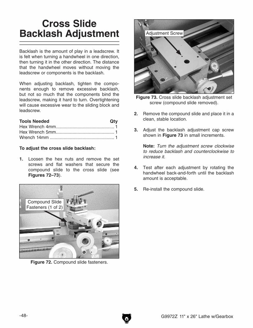
-48- G9972Z 11" x 26" Lathe w/Gearbox
Cross Slide Backlash Adjustment
Backlash is the amount of play in a leadscrew. It is felt when turning a handwheel in one direction, then turning it in the other direction. The distance that the handwheel moves without moving the leadscrew or components is the backlash.
When adjusting backlash, tighten the compo-nents enough to remove excessive backlash, but not so much that the components bind the leadscrew, making it hard to turn. Overtightening will cause excessive wear to the sliding block and leadscrew.
Tools Needed QtyHex Wrench 4mm .............................................. 1Hex Wrench 5mm .............................................. 1Wrench 14mm ................................................... 1
To adjust the cross slide backlash:
1. Loosen the hex nuts and remove the set screws and flat washers that secure the compound slide to the cross slide (see Figures 72–73).
2. Remove the compound slide and place it in a clean, stable location.
3. Adjust the backlash adjustment cap screw shown in Figure 73 in small increments.
Note: Turn the adjustment screw clockwise to reduce backlash and counterclockwise to increase it.
4. Test after each adjustment by rotating the handwheel back-and-forth until the backlash amount is acceptable.
5. Re-install the compound slide.
Figure 72. Compound slide fasteners.
Compound Slide Fasteners (1 of 2)
Figure 73. Cross slide backlash adjustment set screw (compound slide removed).
Adjustment Screw

G9972Z 11" x 26" Lathe w/Gearbox -49-
Gib Adjustments
The gibs on the Model G9972Z control the accu-racy of the cross slide and compound slide move-ments. These gibs are sliding plates that either increase or decrease pressure on the sliding components around them.
The goal of gib adjustment is to remove unneces-sary sloppiness without causing the ways to bind. Tight gibs make the movements more accurate, but harder to perform. Loose gibs make the move-ments sloppy, but easier to perform.
NOTICEExcessively loose gibs may cause poor workpiece finishes, and may cause undue wear of the sliding surfaces and ways. Over-tightening the gibs may cause prema-ture wear of these sliding surfaces.
Tools Needed QtyWrench 8mm ..................................................... 1Hex Wrench 2.5mm ........................................... 1
To adjust the cross slide and compound slide gibs:
1. DISCONNECT LATHE FROM POWER!
2. Loosen the three hex nuts on the side of the slide (see Figures 74–75).
3. Make adjustments in small and equal incre-ments to the three set screws, then test the movement of the slide by rotating the handwheel.
Note: Turning the set screws clockwise will tighten the gib, and turning them counter-clockwise will loosen the gib.
4. When you are satisfied with the gib adjust-ment, keep the set screws from moving and re-tighten the hex nuts to secure the set-tings.
5. Re-check the movement of the slide and, if necessary, repeat Steps 2–4.
Figure 74. Cross slide gib adjustment hex nuts and set screws.
Cross Slide Adjustment Fasteners
Figure 75. Compound slide gib adjustment hex nuts and set screws.
Compound Slide Adjustment Fasteners

-50- G9972Z 11" x 26" Lathe w/Gearbox
Half-Nut Adjustment
Over time and with normal wear, the half-nut may become excessively loose when it engages the leadscrew. The half-nut gib is a flat bar that exerts pressure against the half-nut mechanism. The goal of the half-nut adjustment is to remove unnecessary looseness as the half-nut engages the leadscrew without binding it so tight that the half-nut will not release and possibly cause dam-age to the lathe.
Tools Needed QtyWrench 8mm ..................................................... 1Hex Wrench 5mm .............................................. 1Hex Wrench 2.5mm ........................................... 1
To adjust the half-nut:
1. DISCONNECT LATHE FROM POWER!
2. Move the half-nut lever up to disengage the half-nut from the leadscrew, then remove the thread dial from the apron.
3. Loosen the two adjustment hex nuts, then adjust the set screws in small increments (see Figure 76).
5. Engage the half-nut with the leadscrew, then manually rock the carriage back-and-forth while observing the half-nut for looseness.
6. When you are satisfied with the adjustment, keep the set screws from moving while you re-tighten the hex nuts, then re-install the thread dial.
Shear Pin Replacement
The longitudinal leadscrew is secured to the feed rate gearing in the headstock with the use of a soft-metal shear pin (see Figure 77). The shear pin is designed to break and disengage power to the leadscrew to help protect more expensive lathe components if you crash your carriage or take too large of a cut and overload the lathe.
Tools Needed QtyHammer ............................................................. 1Punch 2.5mm .................................................... 1
To replace the shear pin:
1. DISCONNECT LATHE FROM POWER!
2. Rotate the leadscrew so the shear pin faces up and down. If the connecting collar rotates independently from the leadscrew, then rotate the collar so the shear pin holes align with those in the leadscrew.
3. Use the punch and hammer to drive out the pieces of the old shear pin.
4. Make sure the holes in the collar and leadscrew are aligned, then tap the new shear pin completely through the holes in the collar and leadscrew.
Figure 76. Half-nut gib adjustment hex nuts and set screws (thread dial removed).
Adjustment Fasteners
Half-Nut
Figure 77. Longitudinal leadscrew shear pin.
Shear Pin
Connecting Collar

G9972Z 11" x 26" Lathe w/Gearbox -51-
Ribbed Belt Replacement
The ribbed belt transfers power from the motor to the secondary drive pulley (see Figure 78). If the ribbed belt becomes excessively worn or dam-aged, you will need to replace it.
Tools Needed QtyHex Wrench 5mm (optional) .............................. 1Wrench 14mm ................................................... 1
To replace the ribbed belt:
1. DISCONNECT LATHE FROM POWER!
2. Open the change gear cover and remove the V-belt.
3. Loosen the four motor mount hex nuts and raise the motor up.
Note: It may be more convenient to access the motor mount hex nuts if you first remove the rear splash guard.
4. Roll the old ribbed belt off the pulleys and replace it with a new one, making sure that the belt ribs are seated in the pulley indents.
5. Lower the motor to produce reasonable ten-sion on the ribbed belt, then re-tighten the motor mount hex nuts.
6. Re-install the V-belt and close the cover.
Bearing Preload
This lathe is shipped from the factory with the spindle bearing preload properly adjusted. If the spindle ever develops excessive end-play and the workpiece finish suffers, you can adjust the bear-ing preload to remove the unnecessary end-play and improve the workpiece finish.
Tools Needed QtySpanner Wrench 2" ........................................... 1Large Phillips Screwdriver ................................. 1Dial Indicator with Magnetic Base ..................... 1Heavy Dead Blow Hammer ............................... 1Wooden Block ................................................... 1
To adjust the spindle bearing preload:
1. Run the lathe for approximately 20 minutes on high speed to bring the lathe to normal operating temperature.
2. DISCONNECT LATHE FROM POWER!
3. Remove the chuck or faceplate from the spindle, then open the change gear cover to expose the outboard end of the spindle (see Figure 79).
Figure 78. Ribbed belt and motor mount hex nuts.
Motor Mount
Hex Nuts (2 0f 4)
Figure 79. Outboard end of spindle and spanner nuts.
Spanner Nuts
Spindle Outboard End
Ribbed Belt

-52- G9972Z 11" x 26" Lathe w/Gearbox
4. Insert the handle of a chuck key or similar tool in a spindle indent to keep the spindle from rotating, then remove the outer spanner nut (see Figure 79).
5. Loosen the inner spanner nut one full turn counterclockwise.
Note: You may have to tap on the outboard spindle tube as explained in Step 6 to help unload the spindle preload and break the spanner nut loose.
6. Place a wooden block over the outboard end of the spindle, and hit it soundly with the heavy dead blow hammer (see Figure 80). Your goal is to slide the spindle forward just enough to introduce spindle end-play that you can feel by hand.
Figure 80. Producing detectable spindle end-play.
7. Place a dial indicator on the cross slide and move the carriage toward the spindle until the contact point of the indicator lightly touches the spindle face and the dial reads exactly zero (see Figure 81).
Figure 81. Dial indicator setup.
8. Move the carriage an additional 0.100" toward the headstock.
9. Insert the handle of a chuck key or similar tool in the spindle indents to keep the spindle from rotating, then tighten the inner spanner nut until the indicator dial needle just stops moving and is back to exactly zero.
Note: While tightening the spanner nuts, rock the spindle back and forth slightly to make sure the spindle tapered roller bearings seat properly in their races.
When the dial indicator needle stops mov-ing, there will be no spindle end-play and no bearing preload. It is essential that you find this point without tightening the spanner nut too much and inadvertently preloading the spindle bearings.

G9972Z 11" x 26" Lathe w/Gearbox -53-
Since it takes great effort to turn the inner spanner nut, you may find it difficult to know if you have gone past the zero end-play point or not. It is easiest to have someone watch the dial while you tighten the inner spanner nut. If you think you may have gone past the zero end-play point, take the time to unload the bearings as described earlier, then re-tighten the inner spanner nut until you know you have reached the correct setting.
10. When you are confident that you have adjust-ed the inner spanner nut until zero spindle end-play and preload exist, tighten the inner spanner nut an additional 1⁄8" of a turn clock-wise to introduce the correct amount of spindle bearing preload (see Figure 82).
1/8"
InnerSpannerNut
Figure 82. Turning inner spanner nut 1⁄8" clockwise.
11. Without causing the inner spanner nut to tighten any farther, install and tighten the outer spanner nut against the inner nut.
To confirm that the spindle bearings are cor-rectly preloaded:
1. Re-attach all removed lathe components and prepare it for operation.
2. Install the chuck and tighten the jaws into the center.
3. Set the spindle speed to a medium setting.
4. Connect the lathe to power and turn the lathe spindle ON.
5. Let the lathe run for 20 minutes.
6. Turn the spindle OFF, disconnect the lathe from power, remove the chuck, then check the temperature of the spindle.
— If the spindle nose is slightly warm to the touch, you have correct bearing preload.
— If the spindle nose is hotter than you can comfortably keep your hand on, the preload is too tight and you must repeat the bearing preload adjustment procedure. When repeating the procedure, rotate the inner spanner nut a little less during Step 10 in the preceding instructions.
NOTICEDo not overtighten the outer spanner nut because additional pressure can force the bearings even tighter against the races in the headstock and cause the headstock to compress, crack, or cause bearing failure.

-54- G9972Z 11" x 26" Lathe w/Gearbox
These pages are current at the time of printing. However, in the spirit of improvement, we may make chang-es to the electrical systems of future machines. Study this section carefully. If there are differences between your machine and what is shown in this section, call Technical Support at (570) 546-9663 for assistance BEFORE making any changes to the wiring on your machine.
SECTION 8: WIRING
SHOCK HAZARD. Working on wiring that is con-nected to a power source is extremely dangerous. Touching electrified parts will result in personal injury including but not limited to severe burns, electrocution, or death. Disconnect the power from the machine before servicing electrical com-ponents!
MODIFICATIONS. Modifying the wiring beyond what is shown in the diagram may lead to unpre-dictable results, including serious injury or fire. This includes the installation of unapproved after-market parts.
WIRE CONNECTIONS. All connections must be tight to prevent wires from loosening during machine operation. Double-check all wires dis-connected or connected during any wiring task to ensure tight connections.
CIRCUIT REQUIREMENTS. You MUST follow the requirements at the beginning of this manualwhen connecting your machine to a power source.
WIRE/COMPONENT DAMAGE. Damaged wires or components increase the risk of serious per-sonal injury, fire, or machine damage. If you notice that any wires or components are damaged while performing a wiring task, replace those wires or components.
MOTOR WIRING. The motor wiring shown inthese diagrams is current at the time of printingbut may not match your machine. If you find thisto be the case, use the wiring diagram inside the motor junction box.
CAPACITORS/INVERTERS. Some capacitorsand power inverters store an electrical charge for up to 10 minutes after being disconnected from the power source. To reduce the risk of being shocked, wait at least this long before working on capacitors.
EXPERIENCING DIFFICULTIES. If you are expe-riencing difficulties understanding the information included in this section, contact our Technical Support at (570) 546-9663.
Wiring Safety Instructions
The photos and diagrams included in this section are best viewed in color. You can view these pages in color at www.grizzly.com.
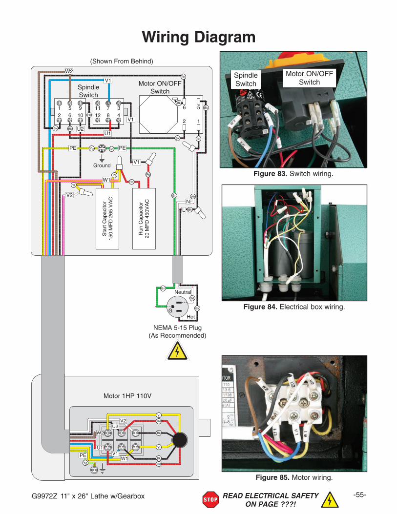
G9972Z 11" x 26" Lathe w/Gearbox -55-READ ELECTRICAL SAFETY ON PAGE ???!
Wiring Diagram
Ground
1 5 9 11 7 32 6 10 12 8 4
6 5
2 1
W2
V1
V2
U1U2
L
NBk
Wt
RdYl
Bk
Bk
RdYl
Bk
BkBk
Bk
Bk
Bk
Sta
rt C
apac
itor
150
MF
D 2
65 V
AC
Run
Cap
acito
r20
MF
D 4
50V
AC
W1
W2
V1
V2
U1
U2
W1
SpindleSwitch
Motor ON/OFFSwitch
Motor 1HP 110V
G
Neutral
Hot
NEMA 5-15 Plug(As Recommended)
GnYg
Gn
Gn
Wt
Bk
Bk
Yl
Rd
Yl
Rd
Bk
Yg
V1
V1
PE PE
PE
(Shown From Behind)
Figure 85. Motor wiring.
Figure 83. Switch wiring.
SpindleSwitch
Motor ON/OFFSwitch
wiring diagram
Figure 84. Electrical box wiring.
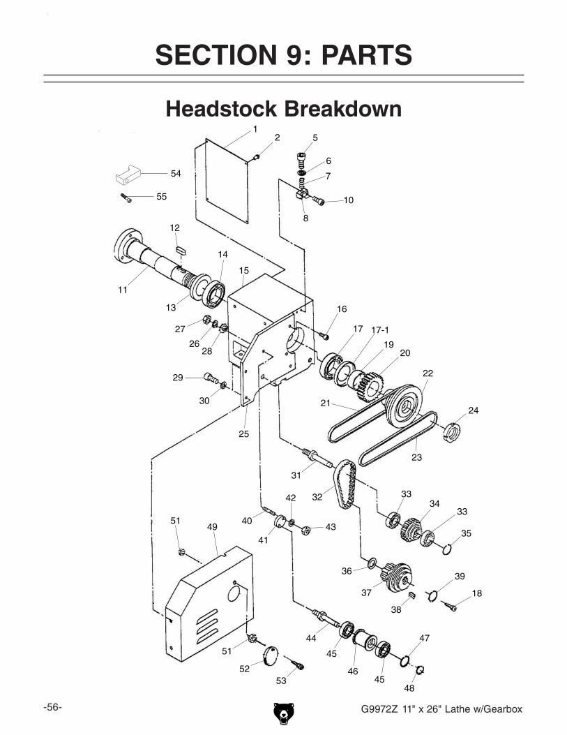
-56- G9972Z 11" x 26" Lathe w/Gearbox
12 5
6
7
8
10
11
12
13
14
15
16
17 17-1
1920
21
22
23
24
25
26
27
28
29
30
31
32 3334
35
36
37
38
39
40
41
42
43
44
45
46
47
48
49
51
5253
33
18
45
51
54
55
Headstock Breakdown
SECTION 9: PARTS

G9972Z 11" x 26" Lathe w/Gearbox -57-
Headstock Parts ListREF PART # DESCRIPTION REF PART # DESCRIPTION1 P9972Z0001 HEADSTOCK NAMEPLATE 29 P9972Z0029 CAP SCREW M5-.8 X 102 P9972Z0002 PHLP HD SCR M4-.7 X 6 30 P9972Z0030 FLAT WASHER 30MM5 P9972Z0005 CAP SCREW M6-1 X 25 31 P9972Z0031 IDLER SHAFT6 P9972Z0006 FLAT WASHER 6MM 32 P9972Z0032 TIMING BELT7 P9972Z0007 COMPRESSION SPRING .8 X 8 X 20 33 P9972Z0033 BALL BEARING 6001 2RS8 P9972Z0008 THREADED BLOCK 34 P9972Z0034 IDLER PULLEY10 P9972Z0010 CAP SCREW M6-1 X 25 35 P9972Z0035 INT RETAINING RING 12MM11 P9972Z0011 SPINDLE 36 P9972Z0036 PULLEY FLAT WASHER12 P9972Z0012 KEY 10 X 10 X 55 37 P9972Z0037 MOTOR PULLEY13 P9972Z0013 SPACER 38 P9972Z0038 KEY 6 X 6 X 4014 P9972Z0014 TAPER ROLLER BEARING 32009 39 P9972Z0039 INT RETAINING RING 10MM15 P9972Z0015 HEADSTOCK CASTING 40 P9972Z0040 THREADED HANDLE ROD16 P9972Z0016 CAP SCREW M8-1.25 X 20 41 P9972Z0041 PIVOT BRACKET17 P9972Z0017 TAPER ROLLER BEARING 32009 42 P9972Z0042 FLAT WASHER 10MM17-1 P9972Z0017-1 BEARING CAP 43 P9972Z0043 HEX NUT M10-1.518 P9972Z0018 PHLP HD SCR M6-1 X 20 44 P9972Z0044 TENSIONING SHAFT19 P9972Z0019 SPACER 45 P9972Z0045 BALL BEARING 6001 2RS20 P9972Z0020 GEAR 45T 46 P9972Z0046 IDLER ROLLER21 P9972Z0021 V-BELT M-29 3L290 47 P9972Z0047 INT RETAINING RING 28MM22 P9972Z0022 SPINDLE PULLEY 48 P9972Z0048 EXT RETAINING RING 12MM23 P9972Z0023 V-BELT M-32 3L320 49 P9972Z0049 CHANGE GEAR COVER24 P9972Z0024 SPANNER NUT M30-3.5 51 P9972Z0051 HEX NUT M5-.825 P9972Z0025 BRACKET PLATE 52 P9972Z0052 OUTBOUND SPINDLE COVER26 P9972Z0026 LOCK WASHER 10MM 53 P9972Z0053 PHLP HD SCR M5-.8 X 1227 P9972Z0027 HEX NUT M10-1.5 54 P9972Z0054 CHUCK LOCK28 P9972Z0028 FLAT WASHER 10MM 55 P9972Z0055 CAP SCREW M6-1 X 14

-58- G9972Z 11" x 26" Lathe w/Gearbox
Change Gears Breakdown
101 102
103
104
106
107
108
201202203204
205
206207
208
209
210
211
212213
214
215
216
217
218
219
220
221
222223
224
REF PART # DESCRIPTION REF PART # DESCRIPTION101 P9972Z0101 SET SCREW M6-1 X 10 210 P9972Z0210 BUSHING102 P9972Z0102 BUSHING 211 P9972Z0211 KEY 4 X 4 X 14103 P9972Z0103 GEAR 45T 212 P9972Z0212 SPACER104 P9972Z0104 GEAR 24T 213 P9972Z0213 GEAR 84T106 P9972Z0106 SHAFT 214 P9972Z0214 FLAT WASHER 6MM107 P9972Z0107 E-CLIP 9MM 215 P9972Z0215 CAP SCREW M6-1 X 10108 P9972Z0108 BALL OILER 6MM 216 P9972Z0216 LOCK WASHER 8MM201 P9972Z0201 CHANGE GEAR BRACKET 217 P9972Z0217 CAP SCREW M8-1.25 X 40202 P9972Z0202 PULLEY SHAFT SQUARE NUT 218 P9972Z0218 GEAR 28T203 P9972Z0203 FLAT WASHER 6MM 219 P9972Z0219 GEAR 35T204 P9972Z0204 SHAFT 220 P9972Z0220 GEAR 63T205 P9972Z0205 KEYED BUSHING 221 P9972Z0221 GEAR 69T206 P9972Z0206 GEAR 127T 222 P9972Z0222 GEAR 70T207 P9972Z0207 GEAR 120T 223 P9972Z0223 GEAR 77T208 P9972Z0208 E-CLIP 9MM 224 P9972Z0224 GEAR 78T209 P9972Z0209 BALL OILER 6MM

G9972Z 11" x 26" Lathe w/Gearbox -59-
Feed Rate Gearbox Breakdown
301 302303
304
305
306
307
308
309
310
311
312
313
314
315
316
317
318
319320321
322323
324
325326
327
328
329
330
331
332
333
334
335
336
337
338339
340341
342343
344345
346347
348
349350
A
A
B
B
A
B
A
302
323322
B
320
322
322

-60- G9972Z 11" x 26" Lathe w/Gearbox
Feed Rate Gearbox Parts ListREF PART # DESCRIPTION REF PART # DESCRIPTION301 P9972Z0301 PLUG 326 P9972Z0326 COLLAR302 P9972Z0302 O-RING 17 X 1.8 327 P9972Z0327 KEY 4 X 4 X 10303 P9972Z0303 BUSHING 328 P9972Z0328 SHAFT304 P9972Z0304 COMBO GEAR 30T/36T/33T 329 P9972Z0329 GEAR 33T305 P9972Z0305 KEY 3 X 3 X 18 330 P9972Z0330 GEAR 30T306 P9972Z0306 SHAFT 331 P9972Z0331 GEAR 35T307 P9972Z0307 BUSHING 332 P9972Z0332 FLANGE308 P9972Z0308 COMBO GEAR 22T/44T/33T 333 P9972Z0333 CAP SCREW M6-1 X 16309 P9972Z0309 PLUG 334 P9972Z0334 SHIFTING FORK310 P9972Z0310 CAP SCREW M5-.8 X 10 335 P9972Z0335 FRONT GEARBOX COVER311 P9972Z0311 BACK GEARBOX COVER 336 P9972Z0336 ROLL PIN 5 X 30312 P9972Z0312 FILL PLUG 337 P9972Z0337 COMPRESSION SPRING .8 X 4.5 X 18313 P9972Z0313 GEARBOX CASTING 338 P9972Z0338 OIL SIGHT GLASS314 P9972Z0314 DRAIN PLUG 339 P9972Z0339 INDICATOR DISC315 P9972Z0315 BRASS SHEAR PIN 340 P9972Z0340 SET SCREW M6-1 X 10316 P9972Z0316 LEADSCREW COLLAR 341 P9972Z0341 STEEL BALL 5MM317 P9972Z0317 BRASS SHEAR PIN 342 P9972Z0342 SHIFT HUB318 P9972Z0318 CAP SCREW M6-1 X 12 343 P9972Z0343 SET SCREW M6-1 X 10319 P9972Z0319 FLANGE 344 P9972Z0344 CAP SCREW M6-1 X 50320 P9972Z0320 BEARING 345 P9972Z0345 CAP SCREW M6-1 X 20321 P9972Z0321 GEAR 33T 346 P9972Z0346 O-RING 6 X 1.8 322 P9972Z0322 EXT RETAINING RING 12MM 347 P9972Z0347 SHAFT323 P9972Z0323 KEY 4 X 4 X 8 348 P9972Z0348 ROLL PIN 5 X 20324 P9972Z0324 GEAR SHAFT 22T 349 P9972Z0349 SHIFT LEVER325 P9972Z0325 GEAR 44T 350 P9972Z0350 SHIFTING FORK

G9972Z 11" x 26" Lathe w/Gearbox -61-
Apron Breakdown
Front
Rear
401
402
403404
405
406
407408
409410
411
412413414
415
416
417
418
419
420
412
422
423
424
425
426
427
428
429
430
431
432
433437
438
439
440
442
443
444
445
446
447
448449
450451
452
453
454
455
456
457458
459460
461
462
463
464
465
466
467
421409
407
414
413
414413
429
447
407
442-1

-62- G9972Z 11" x 26" Lathe w/Gearbox
Apron Parts ListREF PART # DESCRIPTION REF PART # DESCRIPTION401 P9972Z0401 APRON CASTING 433 P9972Z0433 HANDLE M8-1.25 X 83402 P9972Z0402 HANDLE SCREW 437 P9972Z0437 GEAR SHAFT 18T403 P9972Z0403 WORM GEAR 438 P9972Z0438 KEY 4 X 4 X 12404 P9972Z0404 WORM GEAR KEY 439 P9972Z0439 GEAR 42T405 P9972Z0405 HANDLE HUB 440 P9972Z0440 EXT RETAINING RING 12MM406 P9972Z0406 PIN 4 X 20 442 P9972Z0442 HALF NUT INCH407 P9972Z0407 HEX NUT M5-.8 442-1 P9972Z0442-1 HALF NUT BRACKET408 P9972Z0408 SET SCREW M5-.8 X 16 443 P9972Z0443 HALF NUT GIB409 P9972Z0409 STEEL BALL 5MM 444 P9972Z0444 ROLL PIN 2 X 35410 P9972Z0410 COMPRESSION SPRING 445 P9972Z0445 CAP SCREW M4-.7 X 16411 P9972Z0411 HANDLE 446 P9972Z0446 SET SCREW M5-.8 X 25412 P9972Z0412 SET SCREW M6-1 X 6 447 P9972Z0447 HEX NUT M5-.8413 P9972Z0413 FLAT WASHER 10MM 448 P9972Z0448 CONTROL BLOCK414 P9972Z0414 FLAT HD SCR M6-1 X 10 449 P9972Z0449 PIVOT BRACKET415 P9972Z0415 GEAR SHAFT 12T 450 P9972Z0450 CAP SCREW M4-.7 X 20416 P9972Z0416 ROLL PIN 4 X 30 451 P9972Z0451 CAP SCREW M5-.8 X 16417 P9972Z0417 GEAR 43T 452 P9972Z0452 STUD-DE M5-.8 X 36 15 15418 P9972Z0418 HANDLE 453 P9972Z0453 THREAD DIAL BODY419 P9972Z0419 GEAR SHAFT 13T 454 P9972Z0454 PINION GEAR 32T420 P9972Z0420 POWER FEED LEVER BRACKET 455 P9972Z0455 SHAFT421 P9972Z0421 COMPRESSION SPRING 456 P9972Z0456 KEY 3 X 3 X 10422 P9972Z0422 SET SCREW M4-.7 X 10 457 P9972Z0457 LOCK WASHER 8MM423 P9972Z0423 CAP SCREW M6-1 X 30 458 P9972Z0458 HEX NUT M8-1.25424 P9972Z0424 GEAR SHAFT 36T 459 P9972Z0459 THREAD DIAL425 P9972Z0425 SHAFT 460 P9972Z0460 PHLP HD SCR M6-1 X 10426 P9972Z0426 KEY 4 X 4 X 6 461 P9972Z0461 POINTER427 P9972Z0427 GEAR 60T 462 P9972Z0462 STEEL FLUTED RIVET 2 X 5MM428 P9972Z0428 EXT RETAINING RING 14MM 463 P9972Z0463 CAP SCREW M4-.7 X 6429 P9972Z0429 BALL OILER 464 P9972Z0464 REAR APRON COVER430 P9972Z0430 GEAR SHAFT 22T 465 P9972Z0465 FLAT WASHER 4MM431 P9972Z0431 HANDWHEEL 466 P9972Z0466 PHLP HD SCR M4-.7 X 6432 P9972Z0432 ROLL PIN 4 X 24 467 P9972Z0467 ROLL PIN 5 X 12
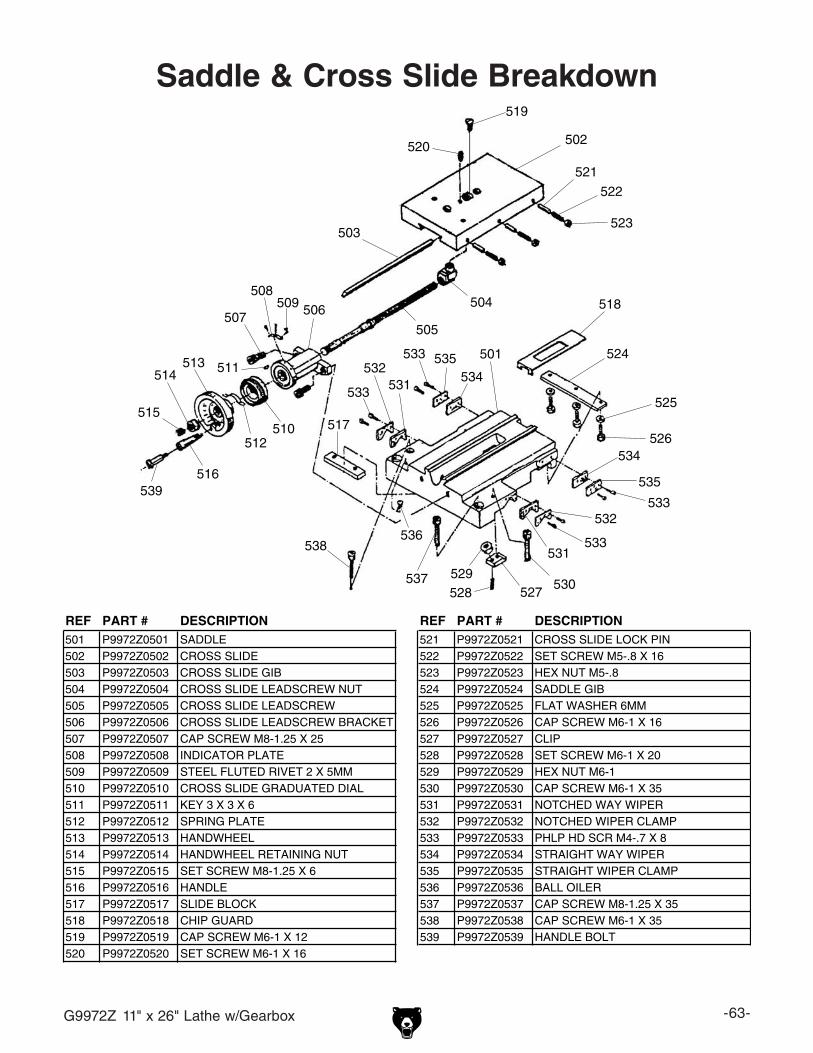
G9972Z 11" x 26" Lathe w/Gearbox -63-
Saddle & Cross Slide Breakdown
501
502
503
504
505
506507
508509
510
511
512
513514
515
516
517
518
519
520
521
522
523
524
525
526
527528529
530
531532
533
534
535
536
537
538
539
531
532
533
533
534535533
REF PART # DESCRIPTION REF PART # DESCRIPTION501 P9972Z0501 SADDLE 521 P9972Z0521 CROSS SLIDE LOCK PIN502 P9972Z0502 CROSS SLIDE 522 P9972Z0522 SET SCREW M5-.8 X 16503 P9972Z0503 CROSS SLIDE GIB 523 P9972Z0523 HEX NUT M5-.8504 P9972Z0504 CROSS SLIDE LEADSCREW NUT 524 P9972Z0524 SADDLE GIB505 P9972Z0505 CROSS SLIDE LEADSCREW 525 P9972Z0525 FLAT WASHER 6MM506 P9972Z0506 CROSS SLIDE LEADSCREW BRACKET 526 P9972Z0526 CAP SCREW M6-1 X 16507 P9972Z0507 CAP SCREW M8-1.25 X 25 527 P9972Z0527 CLIP508 P9972Z0508 INDICATOR PLATE 528 P9972Z0528 SET SCREW M6-1 X 20509 P9972Z0509 STEEL FLUTED RIVET 2 X 5MM 529 P9972Z0529 HEX NUT M6-1510 P9972Z0510 CROSS SLIDE GRADUATED DIAL 530 P9972Z0530 CAP SCREW M6-1 X 35511 P9972Z0511 KEY 3 X 3 X 6 531 P9972Z0531 NOTCHED WAY WIPER512 P9972Z0512 SPRING PLATE 532 P9972Z0532 NOTCHED WIPER CLAMP513 P9972Z0513 HANDWHEEL 533 P9972Z0533 PHLP HD SCR M4-.7 X 8514 P9972Z0514 HANDWHEEL RETAINING NUT 534 P9972Z0534 STRAIGHT WAY WIPER515 P9972Z0515 SET SCREW M8-1.25 X 6 535 P9972Z0535 STRAIGHT WIPER CLAMP516 P9972Z0516 HANDLE 536 P9972Z0536 BALL OILER517 P9972Z0517 SLIDE BLOCK 537 P9972Z0537 CAP SCREW M8-1.25 X 35518 P9972Z0518 CHIP GUARD 538 P9972Z0538 CAP SCREW M6-1 X 35519 P9972Z0519 CAP SCREW M6-1 X 12 539 P9972Z0539 HANDLE BOLT520 P9972Z0520 SET SCREW M6-1 X 16

-64- G9972Z 11" x 26" Lathe w/Gearbox
Compound Slide & Tool Post Breakdown
601
602 603
604
605
606
607
608
609
610
611
612
613
614
615
616
617V2
618
619
620
621
622
623
624
625
626
627
628
629
630 631
608
REF PART # DESCRIPTION REF PART # DESCRIPTION601 P9972Z0601 COMPOUND SLIDE 617V2 P9972Z0617V2 CAP SCREW M5-.8 X 30602 P9972Z0602 SWIVEL BASE 618 P9972Z0618 TOOL POST HANDLE603 P9972Z0603 COMPOUND SLIDE GIB 619 P9972Z0619 TOOL POST HANDLE HUB604 P9972Z0604 CLAMPING RING 620 P9972Z0620 TOOL POST BODY605 P9972Z0605 CLAMPING BASE 621 P9972Z0621 HUB FLAT WASHER606 P9972Z0606 LEADSCREW NUT 622 P9972Z0622 TOOL REST BASE607 P9972Z0607 PLUNGER 623 P9972Z0623 COMPOUND SLIDE LEADSCREW608 P9972Z0608 TOOL POST STUD 624 P9972Z0624 LEADSCREW BRACKET609 P9972Z0609 FLAT WASHER 10MM 625 P9972Z0625 GRADUATED DIAL610 P9972Z0610 SLIDE LOCK PIN 626 P9972Z0626 HANDWHEEL611 P9972Z0611 COMPRESSION SPRING 627 P9972Z0627 HANDLE612 P9972Z0612 TOOL POST CAP SCREW 628 P9972Z0628 KEY 3 X 3 X 8613 P9972Z0613 CAP SCREW M8-1.25 X 25 629 P9972Z0629 SPRING PLATE614 P9972Z0614 CAP SCREW M6-1 X 12 630 P9972Z0630 THREADED COLLAR615 P9972Z0615 SET SCREW M5-.8 X 16 631 P9972Z0631 SET SCREW M8-1.25 X 16616 P9972Z0616 HEX NUT M5-.8

G9972Z 11" x 26" Lathe w/Gearbox -65-
Tailstock Breakdown
701
702
703
704
705
706
707 708
709
710
711
712
713
714715
716717
718
719
720
721
722
723
724 725
726
714
719
REF PART # DESCRIPTION REF PART # DESCRIPTION701 P9972Z0701 TAILSTOCK QUILL MT#3 714 P9972Z0714 SET SCREW M8-1.25 X 25702 P9972Z0702 TAILSTOCK LEADSCREW 715 P9972Z0715 HANDLE703 P9972Z0703 BUSHING 716 P9972Z0716 PLATE704 P9972Z0704 INDICATOR PLATE 717 P9972Z0717 KEY 3 X 3 X 10705 P9972Z0705 HANDWHEEL 718 P9972Z0718 HEX NUT M10-1.5706 P9972Z0706 QUILL LOCK 719 P9972Z0719 STEEL FLUTED RIVET 2 X 5MM707 P9972Z0707 LOCK BUSHING 720 P9972Z0720 OIL PORT 9MM708 P9972Z0708 SET SCREW M6-1 X 12 721 P9972Z0721 CLAMPING PLATE709 P9972Z0709 GRADUATED DIAL 722 P9972Z0722 CLAMPING PLATE HEX NUT710 P9972Z0710 SPRING PLATE 723 P9972Z0723 HEX BOLT M12-1.75 X 100711 P9972Z0711 SPACER 724 P9972Z0724 FLAT WASHER 12MM712 P9972Z0712 TAILSTOCK CASTING 725 P9972Z0725 SET SCREW M5-.8 X 6713 P9972Z0713 TAILSTOCK BASE 726 P9972Z0726 INDICATOR PLATE
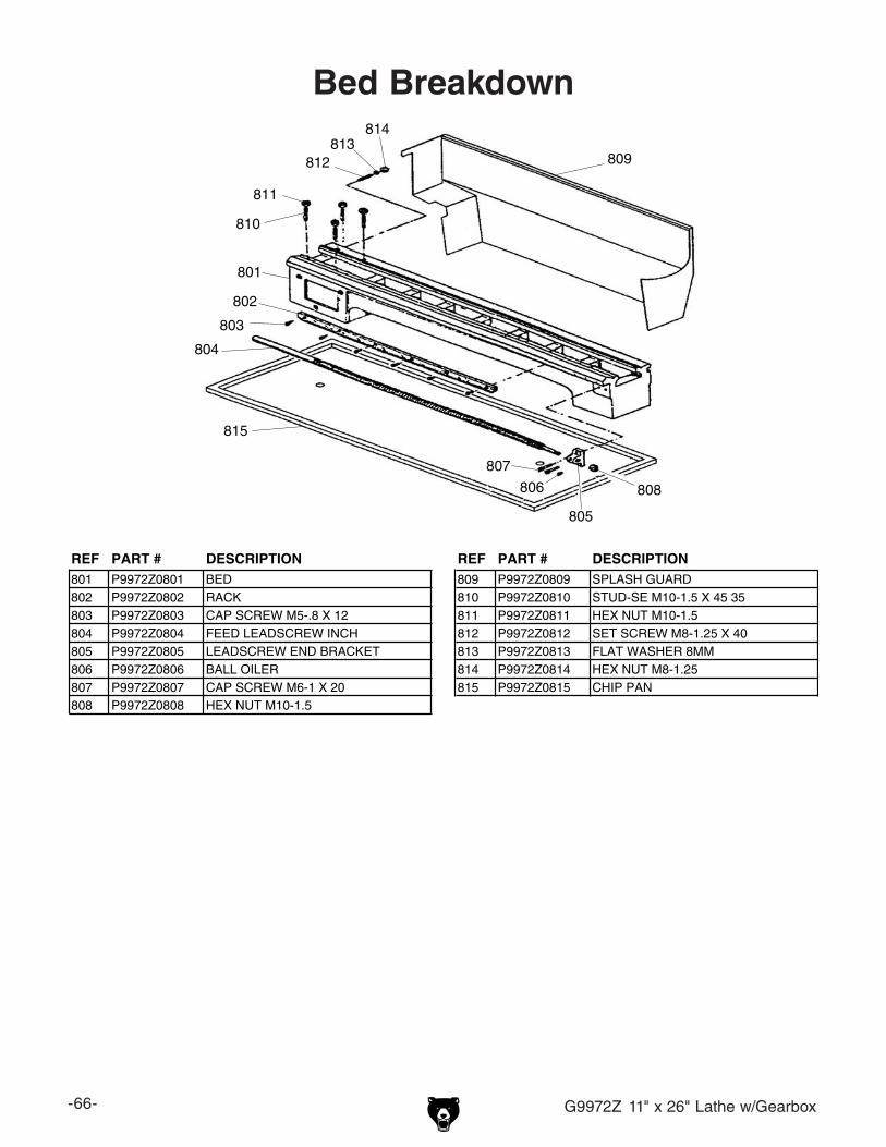
-66- G9972Z 11" x 26" Lathe w/Gearbox
Bed Breakdown
801
802
803
804
805
806
807
808
809
810
811
812813
814
815
REF PART # DESCRIPTION REF PART # DESCRIPTION801 P9972Z0801 BED 809 P9972Z0809 SPLASH GUARD802 P9972Z0802 RACK 810 P9972Z0810 STUD-SE M10-1.5 X 45 35803 P9972Z0803 CAP SCREW M5-.8 X 12 811 P9972Z0811 HEX NUT M10-1.5804 P9972Z0804 FEED LEADSCREW INCH 812 P9972Z0812 SET SCREW M8-1.25 X 40805 P9972Z0805 LEADSCREW END BRACKET 813 P9972Z0813 FLAT WASHER 8MM806 P9972Z0806 BALL OILER 814 P9972Z0814 HEX NUT M8-1.25807 P9972Z0807 CAP SCREW M6-1 X 20 815 P9972Z0815 CHIP PAN808 P9972Z0808 HEX NUT M10-1.5

G9972Z 11" x 26" Lathe w/Gearbox -67-
Steady Rest Breakdown
901
902
903 904
905
906
907908
909
905
REF PART # DESCRIPTION REF PART # DESCRIPTION901 P9972Z0901 STEADY REST CASTING 906 P9972Z0906 ADJUSTING SCREW902 P9972Z0902 FINGER 907 P9972Z0907 CLAMPING PLATE903 P9972Z0903 FINGER T-BOLT 908 P9972Z0908 HEX BOLT M12-1.75 X 65904 P9972Z0904 LOCK WASHER 8MM 909 P9972Z0909 FLAT WASHER 12MM905 P9972Z0905 HEX NUT M6-1
Follow Rest Breakdown
10011002
1003
1004
1005
1006
1007
1008
REF PART # DESCRIPTION REF PART # DESCRIPTION1001 P9972Z1001 FOLLOW REST CASTING 1005 P9972Z1005 HEX NUT M6-11002 P9972Z1002 FINGER 1006 P9972Z1006 FLAT WASHER 8MM1003 P9972Z1003 FINGER T-BOLT 1007 P9972Z1007 CAP SCREW M8-1.25 X 351004 P9972Z1004 ADJUSTING SCREW 1008 P9972Z1008 FLAT WASHER 6MM
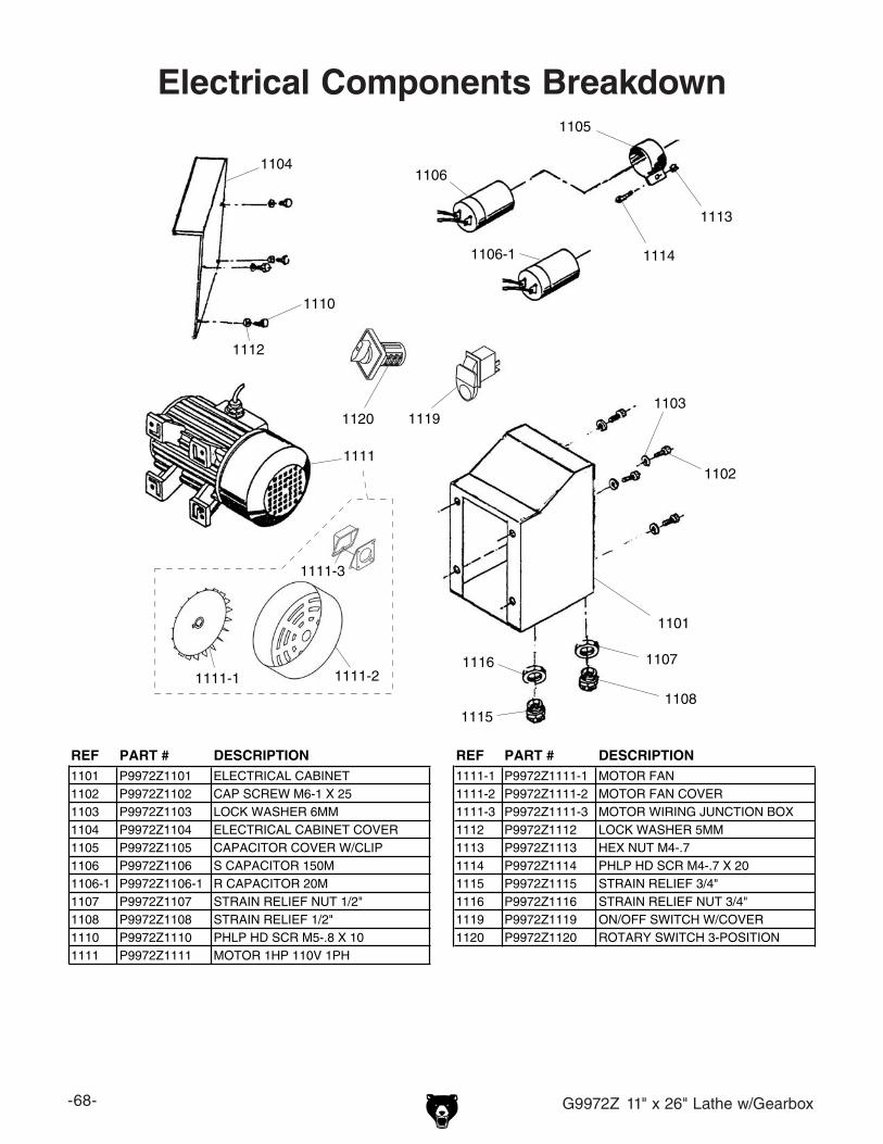
-68- G9972Z 11" x 26" Lathe w/Gearbox
Electrical Components Breakdown
1101
1102
1103
1104
1105
1106
1106-1
1107
1108
1110
1111
1111-1 1111-2
1111-3
1112
1113
1114
1115
1116
11191120
REF PART # DESCRIPTION REF PART # DESCRIPTION1101 P9972Z1101 ELECTRICAL CABINET 1111-1 P9972Z1111-1 MOTOR FAN1102 P9972Z1102 CAP SCREW M6-1 X 25 1111-2 P9972Z1111-2 MOTOR FAN COVER1103 P9972Z1103 LOCK WASHER 6MM 1111-3 P9972Z1111-3 MOTOR WIRING JUNCTION BOX1104 P9972Z1104 ELECTRICAL CABINET COVER 1112 P9972Z1112 LOCK WASHER 5MM1105 P9972Z1105 CAPACITOR COVER W/CLIP 1113 P9972Z1113 HEX NUT M4-.71106 P9972Z1106 S CAPACITOR 150M 1114 P9972Z1114 PHLP HD SCR M4-.7 X 201106-1 P9972Z1106-1 R CAPACITOR 20M 1115 P9972Z1115 STRAIN RELIEF 3/4"1107 P9972Z1107 STRAIN RELIEF NUT 1/2" 1116 P9972Z1116 STRAIN RELIEF NUT 3/4"1108 P9972Z1108 STRAIN RELIEF 1/2" 1119 P9972Z1119 ON/OFF SWITCH W/COVER1110 P9972Z1110 PHLP HD SCR M5-.8 X 10 1120 P9972Z1120 ROTARY SWITCH 3-POSITION1111 P9972Z1111 MOTOR 1HP 110V 1PH

G9972Z 11" x 26" Lathe w/Gearbox -69-
Accessories Breakdown1117
1118
1121
1137
11221123
1124
1125
1126
1127
1128
1129
11301131
1132
1133
1134
1138
1139
1135
1136
REF PART # DESCRIPTION REF PART # DESCRIPTION1117 P9972Z1117 4-JAW CHUCK 6-1/4" 1130 P9972Z1130 HEX WRENCH 3MM1118 P9972Z1118 DEAD CENTER MT#3 1131 P9972Z1131 HEX WRENCH 4MM1121 P9972Z1121 TOOL BOX 1132 P9972Z1132 HEX WRENCH 5MM1122 P9972Z1122 FACEPLATE 8" 1133 P9972Z1133 HEX WRENCH 6MM1123 P9972Z1123 3-JAW CHUCK REVERSE JAW SET 1134 P9972Z1134 HEX WRENCH 8MM1124 P9972Z1124 3-JAW CHUCK KEY 1135 P9972Z1135 FLAT SCREWDRIVER #21125 P9972Z1125 4-JAW CHUCK KEY 1136 P9972Z1136 PHILLIPS SCREWDRIVER #21126 P9972Z1126 CARBIDE-TIPPED DEAD CENTER MT#3 1137 P9972Z1137 3-JAW CHUCK1127 P9972Z1127 WRENCH 8/10MM OPEN ENDS 1138 P9972Z1138 SPINDLE CLAMP1128 P9972Z1128 WRENCH 12/14MM OPEN ENDS 1139 P9972Z1139 CAP SCREW M6-1 X 201129 P9972Z1129 WRENCH 17/19MM OPEN ENDS

-70- G9972Z 11" x 26" Lathe w/Gearbox
1201
1202
1203
1204
1205 1206 12071208
1209
1210
Label Placement
Safety labels warn about machine hazards and ways to prevent injury. The owner of this machine MUST maintain the original location and readability of the labels on the machine. If any label is removed or becomes unreadable, REPLACE that label before using the machine again. Contact Grizzly at (800) 523-4777 or www.grizzly.com to order new labels.
REF PART # DESCRIPTION REF PART # DESCRIPTION1201 P9972Z1201 EYE HAZARD LABEL VERT 1206 P9972Z1206 DISCONNECT POWER LABEL VERT1202 P9972Z1202 READ MANUAL LABEL VERT 1207 P9972Z1207 ENTANGLEMENT HAZARD LABEL1203 P9972Z1203 MACHINE ID LABEL 1208 P9972Z1208 ELECTRICITY LABEL1204 P9972Z1204 THREAD DIAL CHART LABEL 1209 P9972Z1209 GRIZZLY GREEN TOUCH UP PAINT1205 P9972Z1205 PINCH HAZARD LABEL HORIZ 1210 P9972Z1210 LIGHT BEIGE TOUCH UP PAINT

CU
T A
LON
G D
OT
TE
D L
INE
Name _____________________________________________________________________________
Street _____________________________________________________________________________
City _______________________ State _________________________ Zip _____________________
Phone # ____________________ Email _________________________________________________
Model # ____________________ Order # _______________________ Serial # __________________
WARRANTY CARD
The following information is given on a voluntary basis. It will be used for marketing purposes to help us develop better products and services. Of course, all information is strictly confidential.
1. How did you learn about us? ____ Advertisement ____ Friend ____ Catalog ____ Card Deck ____ Website ____ Other:
2. Which of the following magazines do you subscribe to?
3. What is your annual household income? ____ $20,000-$29,000 ____ $30,000-$39,000 ____ $40,000-$49,000 ____ $50,000-$59,000 ____ $60,000-$69,000 ____ $70,000+
4. What is your age group? ____ 20-29 ____ 30-39 ____ 40-49 ____ 50-59 ____ 60-69 ____ 70+
5. How long have you been a woodworker/metalworker? ____ 0-2 Years ____ 2-8 Years ____ 8-20 Years ____20+ Years
6. How many of your machines or tools are Grizzly? ____ 0-2 ____ 3-5 ____ 6-9 ____10+
7. Do you think your machine represents a good value? _____Yes _____No
8. Would you recommend Grizzly Industrial to a friend? _____Yes _____No
9. Would you allow us to use your name as a reference for Grizzly customers in your area? Note: We never use names more than 3 times. _____Yes _____No
10. Comments: _____________________________________________________________________
_________________________________________________________________________________
_________________________________________________________________________________
_________________________________________________________________________________
____ Cabinetmaker & FDM____ Family Handyman____ Hand Loader____ Handy____ Home Shop Machinist____ Journal of Light Cont.____ Live Steam____ Model Airplane News____ Old House Journal____ Popular Mechanics
____ Popular Science____ Popular Woodworking____ Precision Shooter____ Projects in Metal____ RC Modeler____ Rifle____ Shop Notes____ Shotgun News____ Today’s Homeowner____ Wood
____ Wooden Boat____ Woodshop News____ Woodsmith____ Woodwork____ Woodworker West____ Woodworker’s Journal____ Other:

TAPE ALONG EDGES--PLEASE DO NOT STAPLE
FOLD ALONG DOTTED LINE
FOLD ALONG DOTTED LINE
GRIZZLY INDUSTRIAL, INC.P.O. BOX 2069BELLINGHAM, WA 98227-2069
PlaceStampHere
Name_______________________________
Street_______________________________
City______________State______Zip______
Send a Grizzly Catalog to a friend:

WARRANTY AND RETURNS
Grizzly Industrial, Inc. warrants every product it sells for a period of 1 year to the original purchaser from the date of purchase. This warranty does not apply to defects due directly or indirectly to misuse, abuse, negligence, accidents, repairs or alterations or lack of maintenance. This is Grizzly’s sole written warranty and any and all warranties that may be implied by law, including any merchantability or fitness, for any par-ticular purpose, are hereby limited to the duration of this written warranty. We do not warrant or represent that the merchandise complies with the provisions of any law or acts unless the manufacturer so warrants. In no event shall Grizzly’s liability under this warranty exceed the purchase price paid for the product and any legal actions brought against Grizzly shall be tried in the State of Washington, County of Whatcom.
We shall in no event be liable for death, injuries to persons or property or for incidental, contingent, special, or consequential damages arising from the use of our products.
To take advantage of this warranty, contact us by mail or phone and give us all the details. We will then issue you a “Return Number,’’ which must be clearly posted on the outside as well as the inside of the carton. We will not accept any item back without this number. Proof of purchase must accompany the merchandise.
The manufacturers reserve the right to change specifications at any time because they constantly strive to achieve better quality equipment. We make every effort to ensure that our products meet high quality and durability standards and we hope you never need to use this warranty.
Please feel free to write or call us if you have any questions about the machine or the manual.
Thank you again for your business and continued support. We hope to serve you again soon.
WARRANTY AND RETURNS