MODEL G0440/G0441 2 HP & 3 HP CYCLONE DUST …cdn0.grizzly.com/manuals/g0440_m.pdf-2- COPYRIGHTTH...
56
MODEL G0440/G0441 2 HP & 3 HP CYCLONE DUST COLLECTORS OWNER'S MANUAL (For models manufactured since 03/12) COPYRIGHT © APRIL, 2005 BY GRIZZLY INDUSTRIAL, INC. REVISED OCTOBER, 2013 (TS) WARNING: NO PORTION OF THIS MANUAL MAY BE REPRODUCED IN ANY SHAPE OR FORM WITHOUT THE WRITTEN APPROVAL OF GRIZZLY INDUSTRIAL, INC. #TR7027 PRINTED IN TAIWAN Model G0441 Shown With Optional Stand V6.10.13
Transcript of MODEL G0440/G0441 2 HP & 3 HP CYCLONE DUST …cdn0.grizzly.com/manuals/g0440_m.pdf-2- COPYRIGHTTH...

MODEL G0440/G04412 HP & 3 HP
CYCLONE DUST COLLECTORSOWNER'S MANUAL
(For models manufactured since 03/12)
COPYRIGHT © APRIL, 2005 BY GRIZZLY INDUSTRIAL, INC. REVISED OCTOBER, 2013 (TS)WARNING: NO PORTION OF THIS MANUAL MAY BE REPRODUCED IN ANY SHAPE
OR FORM WITHOUT THE WRITTEN APPROVAL OF GRIZZLY INDUSTRIAL, INC.#TR7027 PRINTED IN TAIWAN
Model G0441 ShownWith Optional Stand
V6.10.13

This manual provides critical safety instructions on the proper setup, operation, maintenance, and service of this machine/tool. Save this document, refer to it often, and use it to instruct other operators.
Failure to read, understand and follow the instructions in this manual may result in fire or serious personal injury—including amputation, electrocution, or death.
The owner of this machine/tool is solely responsible for its safe use. This responsibility includes but is not limited to proper installation in a safe environment, personnel training and usage authorization, proper inspection and maintenance, manual availability and compre-hension, application of safety devices, cutting/sanding/grinding tool integrity, and the usage of personal protective equipment.
The manufacturer will not be held liable for injury or property damage from negligence, improper training, machine modifications or misuse.
Some dust created by power sanding, sawing, grinding, drilling, and other construction activities contains chemicals known to the State of California to cause cancer, birth defects or other reproductive harm. Some examples of these chemicals are:
• Lead from lead-based paints.• Crystalline silica from bricks, cement and other masonry products.• Arsenic and chromium from chemically-treated lumber.
Your risk from these exposures varies, depending on how often you do this type of work. To reduce your exposure to these chemicals: Work in a well ventilated area, and work with approved safety equip-ment, such as those dust masks that are specially designed to filter out microscopic particles.

Table of ContentsINTRODUCTION ............................................... 2
Machine Description ...................................... 2Contact Info.................................................... 2Manual Accuracy ........................................... 2Identification ................................................... 3G0440 Machine Data Sheet .......................... 4G0441 Machine Data Sheet .......................... 6
SECTION 1: SAFETY ....................................... 8Safety Instructions for Machinery .................. 8Additional Safety for Dust Collectors ........... 10
SECTION 2: POWER SUPPLY ...................... 11Availability .................................................. 11Full-Load Current Rating ........................... 11Circuit Requirements ................................. 11G0440 Circuit Requirements ..................... 11G0441 Circuit Requirements ..................... 11Connection Type ....................................... 12Grounding Instructions .............................. 12Extension Cords ........................................ 12
SECTION 3: SETUP ....................................... 13Unpacking .................................................... 13Needed for Setup ......................................... 13G0440 Inventory .......................................... 14G0441 Inventory .......................................... 15Site Considerations ...................................... 16Wall Mounting .............................................. 17
Materials Needed for Standard Wood Framed Walls ............................................ 17Materials Needed for Concrete/Masonry Wall ............................................................ 18
Assembly ..................................................... 19Test Run ...................................................... 25
SECTION 4: DESIGNING THE SYSTEM ....... 26General ........................................................ 26Duct Material ................................................ 26
Metal Duct ................................................. 27Flexible Duct .............................................. 27
System Design ............................................. 28Step 1. Decide Who Will Design ............... 28Step 2. Sketch Your Shop Layout ............. 28Step 3. Sketch a Basic Duct Layout .......... 28Step 4. Determine Required CFMs ........... 29Determining Main Line Duct Size .............. 30Determining Branch Line Duct Size .......... 30Planning Drop Downs ................................ 30Multiple Dust Ports .................................... 31Two Machines on Same Branch Line ....... 31Calculating Duct Resistance ..................... 31Example Materials List .............................. 33
System Grounding ....................................... 34
SECTION 5: OPERATIONS ........................... 35Remote Control ............................................ 35General ........................................................ 35
SECTION 6: ACCESSORIES ......................... 36
SECTION 7: MAINTENANCE ......................... 38Emptying Drum ............................................ 38Cleaning Filter .............................................. 38Rinsing Filter ................................................ 38Removing/Replacing Filter ........................... 39
SECTION 8: SERVICE ................................... 41Troubleshooting ........................................... 41
SECTION 9: WIRING ...................................... 42Wiring Safety Instructions ............................ 42G0440 Wiring Diagram ................................ 43G0441 Wiring Diagram ................................ 44G0440/G0441 Electrical Components ......... 45
SECTION 10: PARTS ..................................... 46G0440 Main ................................................. 46G0441 Main ................................................. 48
WARRANTY AND RETURNS ........................ 53

-2- Model G0440/G0441 (Mfg. Since 03/12)
The Model G0440/G0441 is a 2-stage cyclone wood dust collector capable of collecting dust from multiple machines running simultaneously.
Cyclonic action separates the heavy dust and chips from the fine particles and drops them into the steel collection drum. Any remaining fine dust travels past the impeller and is trapped by the pleated cartridge filter. With the use of the cable and pulley system on the outside of the filter assembly, the caked dust is brushed down into the collection bag.
The machine is controlled by the remote magnetic switch mounted to it or by the IR remote control-ler—each control includes timer options.
INTRODUCTION
Machine Description
We are proud to provide a high-quality owner’s manual with your new machine!
We made every effort to be exact with the instruc-tions, specifications, drawings, and photographs contained inside. Sometimes we make mistakes, but our policy of continuous improvement also means that sometimes the machine you receive will be slightly different than what is shown in the manual.
If you find this to be the case, and the difference between the manual and machine leaves you confused about a procedure, check our website for an updated version. We post current manuals and manual updates for free on our website at www.grizzly.com.
Alternatively, you can call our Technical Support for help. Before calling, please write down the Manufacture Date and Serial Number stamped into the machine ID label (see below). This infor-mation helps us determine if updated documenta-tion is available for your machine.
Manufacture Date
Serial Number
Manual Accuracy
We stand behind our machines. If you have any questions or need help, use the information below to contact us. Before contacting, please get the serial number and manufacture date of your machine. This will help us help you faster.
Grizzly Technical Support1203 Lycoming Mall Circle
Muncy, PA 17756Phone: (570) 546-9663
Email: [email protected]
We want your feedback on this manual. What did you like about it? Where could it be improved? Please take a few minutes to give us feedback.
Grizzly Documentation ManagerP.O. Box 2069
Bellingham, WA 98227-2069Email: [email protected]
Contact Info

Model G0440/G0441 (Mfg. Since 03/12) -3-
Identification
To reduce the risk of serious injury when using this machine, read and understand this entire manual before beginning any operations.
Figure 1. Identification (Model G0441 shown with optional stand).
CanisterFilter Assembly
VacuumHose
CollectionDrum
OptionalStand
RemoteMagnetic Switch
InletPort
BlowerHousing
Motor

-4- Model G0440/G0441 (Mfg. Since 03/12)
The information contained herein is deemed accurate as of 11/6/2013 and represents our most recent product specifications.Due to our ongoing improvement efforts, this information may not accurately describe items previously purchased. PAGE 1 OF 3Model G0440
MACHINE DATASHEET
Customer Service #: (570) 546-9663 · To Order Call: (800) 523-4777 · Fax #: (800) 438-5901
MODEL G0440 2 HP CYCLONE DUST COLLECTORProduct Dimensions:
Weight.............................................................................................................................................................. 287 lbs.Width (side-to-side) x Depth (front-to-back) x Height..................................................................... 59 x 38 x 93-1/2 in.Footprint (Length x Width)............................................................................................................... 32-1/2 x 32-7/8 in.
Shipping Dimensions:
Carton #1Type........................................................................................................................................... Cardboard BoxContent................................................................................................................................................. MachineWeight.................................................................................................................................................... 314 lbs.Length x Width x Height............................................................................................................. 54 x 28 x 35 in.Must Ship Upright......................................................................................................................................... Yes
Carton #2Type........................................................................................................................................... Cardboard BoxContent......................................................................................................................................... Canister FilterWeight...................................................................................................................................................... 38 lbs.Length x Width x Height............................................................................................................. 49 x 18 x 18 in.Must Ship Upright.......................................................................................................................................... No
Electrical:
Power Requirement........................................................................................................... 220V, Single-Phase, 60 HzPrewired Voltage.................................................................................................................................................. 220VFull-Load Current Rating........................................................................................................................................ 14AMinimum Circuit Size.............................................................................................................................................. 20AConnection Type......................................................................................................................... Permanent HardwireSwitch Type......................................................................... Remote Control Magnetic Switch w/Overload Protection
Motors:Main
Type.................................................................................................. TEFC Capacitor-Start Induction (Class F)Horsepower................................................................................................................................................ 2 HPPhase............................................................................................................................................ Single-PhaseAmps............................................................................................................................................................ 14ASpeed................................................................................................................................................ 3450 RPMPower Transfer ............................................................................................................................... Direct DriveBearings..................................................................................................... Shielded & Permanently Lubricated

Model G0440/G0441 (Mfg. Since 03/12) -5-
The information contained herein is deemed accurate as of 11/6/2013 and represents our most recent product specifications.Due to our ongoing improvement efforts, this information may not accurately describe items previously purchased. PAGE 2 OF 3Model G0440
Main Specifications:
Operation
Dust Collector Type.......................................................................................................... Two-Stage (Cyclone)Approved Dust Types................................................................................................................................ WoodFilter Type............................................................................................................................... Pleated CartridgeAirflow Capacity............................................................................................................ 1354 CFM @ 2.5 in. SPMax Static Pressure (at 0 CFM)............................................................................................................. 10.4 in.Main Inlet Size............................................................................................................................................. 7 in.Inlet Adapter Included.................................................................................................................................... NoMachine Collection Capacity At One Time....................................................................................... 3 MachinesMaximum Material Collection Capacity................................................................................................ 4.7 cu. ft.Filtration Rating............................................................................................................................ 0.2 – 2 MicronFilter Surface Area................................................................................................................................ 96 sq. ft.
Bag Information
No of Lower Bags............................................................................................................................................. 1Lower Bag Diameter............................................................................................................................ 15-3/4 in.
Canister Information
No of Canister Filters........................................................................................................................................ 1Canister Filter Diameter....................................................................................................................... 15-3/4 in.Canister Filter Length.......................................................................................................................... 46-3/4 in.Collection Drum Size......................................................................................................................... 35 Gallons
Impeller Information
Impeller Type...................................................................................................................................... Radial FinImpeller Size........................................................................................................................................ 14-1/2 in.
Construction
Lower Bag...................................................................................................................................... Clear PlasticCanister............................................................................................................................ Spun Bond PolyesterFrame....................................................................................................................... Steel Sheet Metal (14 ga.)Impeller....................................................................................................................................................... SteelPaint........................................................................................................................................... Powder CoatedBlower Housing......................................................................................................................... 11 Gauge SteelBody.......................................................................................................................................... 14 Gauge SteelCollection Drum..................................................................................................................................... Steel
Other
Optional Stand......................................................................................................................................... H7499
Other Specifications:
Country Of Origin ............................................................................................................................................. TaiwanWarranty ........................................................................................................................................................... 1 YearApproximate Assembly & Setup Time ............................................................................................................. 3 HoursSerial Number Location .................................................................................................................................. ID LabelSound Rating ............................................................................................................................................. 83 – 85 dBISO 9001 Factory .................................................................................................................................................... NoCSA Certified ......................................................................................................................................................... YesAwards ....................................................................................................... American Woodworker Editor's Pick 2006

-6- Model G0440/G0441 (Mfg. Since 03/12)
G0441 Machine Data Sheet
The information contained herein is deemed accurate as of 11/6/2013 and represents our most recent product specifications.Due to our ongoing improvement efforts, this information may not accurately describe items previously purchased. PAGE 1 OF 3Model G0441
MACHINE DATASHEET
Customer Service #: (570) 546-9663 · To Order Call: (800) 523-4777 · Fax #: (800) 438-5901
MODEL G0441 3 HP CYCLONE DUST COLLECTORProduct Dimensions:
Weight.............................................................................................................................................................. 347 lbs.Width (side-to-side) x Depth (front-to-back) x Height............................................................. 60-1/4 x 38-1/2 x 109 in.Footprint (Length x Width)............................................................................................................... 32-7/8 x 32-7/8 in.
Shipping Dimensions:
Carton #1Type........................................................................................................................................... Cardboard BoxContent................................................................................................................................................. MachineWeight.................................................................................................................................................... 354 lbs.Length x Width x Height............................................................................................................. 53 x 28 x 34 in.Must Ship Upright......................................................................................................................................... Yes
Carton #2Type........................................................................................................................................... Cardboard BoxContent......................................................................................................................................... Canister FilterWeight...................................................................................................................................................... 46 lbs.Length x Width x Height............................................................................................................. 49 x 22 x 22 in.Must Ship Upright.......................................................................................................................................... No
Electrical:
Power Requirement........................................................................................................... 220V, Single-Phase, 60 HzPrewired Voltage.................................................................................................................................................. 220VFull-Load Current Rating........................................................................................................................................ 22AMinimum Circuit Size.............................................................................................................................................. 40AConnection Type.......................................................................................................................... Permanent HardwireSwitch Type......................................................................... Remote Control Magnetic Switch w/Overload Protection
Motors:Main
Type.................................................................................................. TEFC Capacitor-Start Induction (Class F)Horsepower................................................................................................................................................ 3 HPPhase............................................................................................................................................ Single-PhaseAmps............................................................................................................................................................ 22ASpeed................................................................................................................................................ 3450 RPMPower Transfer ............................................................................................................................... Direct DriveBearings..................................................................................................... Shielded & Permanently Lubricated

Model G0440/G0441 (Mfg. Since 03/12) -7-
The information contained herein is deemed accurate as of 11/6/2013 and represents our most recent product specifications.Due to our ongoing improvement efforts, this information may not accurately describe items previously purchased. PAGE 2 OF 3Model G0441
Main Specifications:
Operation
Dust Collector Type.......................................................................................................... Two-Stage (Cyclone)Approved Dust Types................................................................................................................................ WoodFilter Type............................................................................................................................... Pleated CartridgeAirflow Capacity............................................................................................................ 1654 CFM @ 2.0 in. SPMax Static Pressure (at 0 CFM)............................................................................................................. 14.2 in.Main Inlet Size............................................................................................................................................. 8 in.Inlet Adapter Included.................................................................................................................................... NoMachine Collection Capacity At One Time....................................................................................................... 3Maximum Material Collection Capacity................................................................................................ 7.4 cu. ft.Filtration Rating............................................................................................................................ 0.2 – 2 MicronFilter Surface Area.............................................................................................................................. 113 sq. ft.
Bag Information
No of Lower Bags............................................................................................................................................. 1Lower Bag Diameter............................................................................................................................ 19-3/4 in.
Canister Information
No of Canister Filters........................................................................................................................................ 1Canister Filter Diameter................................................................................................................... 19-11/16 in.Canister Filter Length.......................................................................................................................... 46-1/4 in.Collection Drum Size......................................................................................................................... 55 Gallons
Impeller Information
Impeller Type...................................................................................................................................... Radial FinImpeller Size........................................................................................................................................ 15-1/2 in.
Construction
Lower Bag...................................................................................................................................... Clear PlasticCanister............................................................................................................................ Spun Bond PolyesterFrame....................................................................................................................... Steel Sheet Metal (14 ga.)Impeller....................................................................................................................................................... SteelPaint........................................................................................................................................... Powder CoatedBlower Housing......................................................................................................................... 11 Gauge SteelBody.......................................................................................................................................... 14 Gauge SteelCollection Drum..................................................................................................................................... Steel
Other
Optional Stand......................................................................................................................................... H7509
Other Specifications:
Country Of Origin ............................................................................................................................................. TaiwanWarranty ........................................................................................................................................................... 1 YearApproximate Assembly & Setup Time ............................................................................................................. 3 HoursSerial Number Location .................................................................................................................................. ID LabelSound Rating ............................................................................................................................................. 83 – 85 dBISO 9001 Factory .................................................................................................................................................... NoCSA Certified ......................................................................................................................................................... YesAwards ....................................................................................................... American Woodworker Editor's Pick 2006

-8- Model G0440/G0441 (Mfg. Since 03/12)
ELECTRICAL EQUIPMENT INJURY RISKS. You can be shocked, burned, or killed by touching live electrical components or improperly grounded machinery. To reduce this risk, only allow qualified service personnel to do electrical installation or repair work, and always disconnect power before accessing or exposing electrical equipment.
DISCONNECT POWER FIRST. Always discon-nect machine from power supply BEFORE making adjustments, changing tooling, or servicing machine. This prevents an injury risk from unintended startup or contact with live electrical components.
EYE PROTECTION. Always wear ANSI-approved safety glasses or a face shield when operating or observing machinery to reduce the risk of eye injury or blindness from flying particles. Everyday eyeglasses are not approved safety glasses.
OWNER’S MANUAL. Read and understand this owner’s manual BEFORE using machine.
TRAINED OPERATORS ONLY. Untrained oper-ators have a higher risk of being hurt or killed. Only allow trained/supervised people to use this machine. When machine is not being used, dis-connect power, remove switch keys, or lock-out machine to prevent unauthorized use—especially around children. Make workshop kid proof!
DANGEROUS ENVIRONMENTS. Do not use machinery in areas that are wet, cluttered, or have poor lighting. Operating machinery in these areas greatly increases the risk of accidents and injury.
MENTAL ALERTNESS REQUIRED. Full mental alertness is required for safe operation of machin-ery. Never operate under the influence of drugs or alcohol, when tired, or when distracted.
For Your Own Safety, Read Instruction Manual Before Operating This Machine
The purpose of safety symbols is to attract your attention to possible hazardous conditions. This manual uses a series of symbols and signal words intended to convey the level of impor-tance of the safety messages. The progression of symbols is described below. Remember that safety messages by themselves do not eliminate danger and are not a substitute for proper accident prevention measures. Always use common sense and good judgment.
Indicates a potentially hazardous situation which, if not avoided, MAY result in minor or moderate injury. It may also be used to alert against unsafe practices.
Indicates a potentially hazardous situation which, if not avoided, COULD result in death or serious injury.
Indicates an imminently hazardous situation which, if not avoided, WILL result in death or serious injury.
This symbol is used to alert the user to useful information about proper operation of the machine.NOTICE
Safety Instructions for Machinery
SECTION 1: SAFETY

Model G0440/G0441 (Mfg. Since 03/12) -9-
WEARING PROPER APPAREL. Do not wearclothing, apparel or jewelry that can becomeentangled in moving parts. Always tie back orcover longhair.Wearnon-slip footwear toavoidaccidentalslips,whichcouldcauselossofwork-piececontrol.
hAzARdOus dusT. Dust created while usingmachinery may cause cancer, birth defects, orlong-term respiratorydamage.Beawareofdusthazardsassociatedwitheachworkpiecematerial,andalwayswearaNIOSH-approvedrespiratortoreduceyourrisk.
hEARING PROTECTION. Always wear hear-ing protectionwhenoperating or observing loudmachinery. Extended exposure to this noisewithouthearingprotectioncancausepermanenthearingloss.
REMOVE AdJusTING TOOLs. Tools left onmachinery can become dangerous projectilesuponstartup.Neverleavechuckkeys,wrenches,or any other tools on machine. Always verifyremovalbeforestarting!
INTENdEd usAGE. Only use machine for itsintendedpurposeandnevermakemodificationsnot approved by Grizzly. Modifying machine orusing it differently than intended may result inmalfunctionormechanicalfailurethatcanleadtoseriouspersonalinjuryordeath!
AWKWARd POsITIONs. Keep proper footingandbalanceatalltimeswhenoperatingmachine.Donotoverreach!Avoidawkwardhandpositionsthatmakeworkpiece control difficult or increasetheriskofaccidentalinjury.
ChILdREN & BYsTANdERs. Keepchildrenandbystandersatasafedistancefromtheworkarea.Stopusingmachineiftheybecomeadistraction.
GuARds & COVERs.Guardsandcoversreduceaccidental contact with moving parts or flyingdebris. Make sure they are properly installed,undamaged,andworkingcorrectly.
FORCING MAChINERY.Donotforcemachine.Itwilldo the jobsaferandbetterat the rate forwhichitwasdesigned.
NEVER sTANd ON MAChINE. Serious injurymay occur ifmachine is tipped or if the cuttingtoolisunintentionallycontacted.
sTABLE MAChINE. Unexpectedmovementdur-ing operation greatly increases risk of injury orlossofcontrol.Beforestarting,verifymachineisstableandmobilebase(ifused)islocked.
usE RECOMMENdEd ACCEssORIEs.Consultthisowner’smanualorthemanufacturerforrec-ommended accessories.Using improper acces-sorieswillincreasetheriskofseriousinjury.
uNATTENdEd OPERATION. To reduce therisk of accidental injury, turnmachineoff andensure all moving parts completely stop beforewalking away. Never leave machine runningwhileunattended.
MAINTAIN WITh CARE.Followallmaintenanceinstructions and lubrication schedules to keepmachine in good working condition. A machinethat is improperlymaintained couldmalfunction,leadingtoseriouspersonalinjuryordeath.
ChECK dAMAGEd PARTs. Regularly inspectmachine for any condition that may affect safeoperation.Immediatelyrepairorreplacedamagedormis-adjustedpartsbeforeoperatingmachine.
MAINTAIN POWER CORds. Whendisconnect-ing cord-connected machines from power, grabandpulltheplug—NOTthecord.Pullingthecordmay damage the wires inside. Do not handlecord/plugwithwethands.Avoidcorddamagebykeepingitawayfromheatedsurfaces,hightrafficareas,harshchemicals,andwet/damplocations.
EXPERIENCING dIFFICuLTIEs. If at any timeyouexperiencedifficultiesperformingtheintend-edoperation,stopusingthemachine!ContactourTechnicalSupportat(570)546-9663.

-10- Model G0440/G0441 (Mfg. Since 03/12)
Additional Safety for Dust Collectors
INTENDED USE. This dust collector is designed for collecting wood dust and chips from wood-working machines. DO NOT use it to collect metal, dirt, drywall, asbestos, lead paint, silica, liq-uids, aerosols, biohazards, or explosive materials. Collecting the wrong materials can result in seri-ous inhalation hazards, fire, or machine damage.
HAZARDOUS DUST. Dust created while using machinery may cause cancer, birth defects, or long-term respiratory damage. Be aware of dust hazards associated with each workpiece material, and always wear a NIOSH-approved respirator to reduce your risk.
WEAR A RESPIRATOR. Fine dust that is too small to be caught in the filter will be blown into the ambient air during operation. To reduce your risk of respiratory damage from this fine dust, always wear a NIOSH approved respirator during operation and for a short time after. Also, never collect dust from any type of hazardous material.
IMPELLER HAZARDS. All objects collected by this machine can strike the rotating impeller. DO NOT place hands, hair, clothing, or tools near the open inlet during operation. The powerful suction could easily pull them into the impeller, which will cause serious personal injury or damage to the machine. Always keep small animals and children away from open dust collection inlets.
DISCONNECTING POWER SUPPLY. Turn the switch OFF, disconnect the dust collector from the power supply, and allow the impeller to come to a complete stop before leaving the machine unattended or doing any service, cleaning, main-tenance, or adjustments.
REGULAR CLEANING. Regularly check/empty the collection bags or drum to avoid the buildup of fine dust that can increase the risk of fire. Make sure to regularly clean the surrounding area where the machine is operated—excessive dust buildup on overhead lights, heaters, electrical panels, or other heat sources will increase the risk of fire.
SUSPENDED DUST PARTICLES AND IGNITION SOURCES. DO NOT operate the dust collector in areas where explosion risks are high. Areas of high risk include, but are not limited to, areas near pilot lights, open flames, or other ignition sources.
AVOIDING SPARKS. Avoid collecting steel frag-ments or stones. These items can produce sparks when they strike the impeller, which can smol-der in wood dust for a long time before a fire is detected. If you accidentally cut into wood con-taining tramp metal (nails, staples, spikes, etc.), immediately turn OFF the dust collector, discon-nect it from power, and wait for the impeller to stop—then empty the collection container into an approved airtight metal container.
OPERATING LOCATION. To reduce respira-tory exposure to fine dust, locate permanently installed dust collectors away from the working area or in another room. DO NOT place the dust collector where it can be exposed to rain or mois-ture—exposure to water creates a shock hazard and will reduce the life of the machine.
FIRE SUPPRESSION. Only operate the dust col-lector in locations that contain a fire suppression system or have a fire extinguisher nearby.
STATIC ELECTRICITY. Plastic dust lines gener-ate high amounts of static electricity as dust chips pass through them. Although rare, sparks caused by static electricity can cause explosions or fire. To reduce this risk, make sure all dust lines are thoroughly grounded by using a grounding wire.
EMPTYING DUST. When emptying dust from the collection container, wear a respirator and safety glasses. Empty dust away from ignition sources and into an approved container.
DUST ALLERGIES. Dust from certain woods will cause an allergic reaction. Always make sure you know what type of wood dust you are exposed to in the event that this happens.

Model G0440/G0441 (Mfg. Since 03/12) -11-
SECTION 2: POWER SUPPLY
Availability Circuit RequirementsBefore installing the machine, consider the avail-ability and proximity of the required power supply circuit. If an existing circuit does not meet the requirements for this machine, a new circuit must be installed. To minimize the risk of electrocution, fire, or equipment damage, installation work and electrical wiring must be done by an electrican or qualified service personnel in accordance with all applicable codes and standards.
G0440 Full-Load Current Rating ....... 14 AmpsG0441 Full-Load Current Rating ....... 22 Amps
For your own safety and protection of property, consult an electrician if you are unsure about wiring practices or electrical codes in your area.
Note: The circuit requirements listed in this man-ual apply to a dedicated circuit—where only one machine will be running at a time. If this machine will be connected to a shared circuit where mul-tiple machines will be running at the same time, consult a qualified electrician to ensure that the circuit is properly sized for safe operation.
A power supply circuit includes all electrical equipment between the breaker box or fuse panel in the building and the machine. The power sup-ply circuit used for this machine must be sized to safely handle the full-load current drawn from the machine for an extended period of time. (If this machine is connected to a circuit protected by fuses, use a time delay fuse marked D.)
G0440 Circuit Requirements
Nominal Voltage .............................. 220V/240VCycle ..........................................................60 HzPhase ........................................... Single-PhaseCircuit Rating ...................................... 20 Amps
G0441 Circuit Requirements
Nominal Voltage .............................. 220V/240VCycle ..........................................................60 HzPhase ........................................... Single-PhaseCircuit Rating ...................................... 40 Amps
This machine is prewired to operate on a 220V power supply circuit that has a verified ground and meets the following requirements:
This machine is prewired to operate on a 220V power supply circuit that has a verified ground and meets the following requirements:
Full-Load Current RatingThe full-load current rating is the amperage a machine draws at 100% of the rated output power. On machines with multiple motors, this is the amperage drawn by the largest motor or sum of all motors and electrical devices that might operate at one time during normal operations.
The full-load current is not the maximum amount of amps that the machine will draw. If the machine is overloaded, it will draw additional amps beyond the full-load rating.
If the machine is overloaded for a sufficient length of time, damage, overheating, or fire may result—especially if connected to an undersized circuit. To reduce the risk of these hazards, avoid over-loading the machine during operation and make sure it is connected to a power supply circuit that meets the requirements in the following section.
Electrocution, fire, or equipment damage may occur if machine is not correctly grounded and connected to the power supply.

-12- Model G0440/G0441 (Mfg. Since 03/12)
Extension CordsSince this machine must be permanently con-nected to the power supply, an extension cord cannot be used.
Connection Type
Figure 1. Typical setup of a permanently connected machine.
PowerSource
LockingDisconnect Switch
Machine
Ground Ground
ConduitConduit
A permanently connected (hardwired) power sup-ply is typically installed with wires running through mounted and secured conduit. A disconnecting means, such as a locking switch (see following Figure), must be provided to allow the machine to be disconnected (isolated) from the power supply when required. This installation must be performed by an electrician in accordance with all applicable electrical codes and ordinances.
Serious injury could occur if you connect the machine to power before completing the setup process. DO NOT connect to power until instructed later in this manual.
Grounding InstructionsIn the event of a malfunction or breakdown, grounding provides a path of least resistance for electrical current to reduce the risk of electric shock. A permanently connected machine must be connected to a grounded metal permanent wir-ing system; or to a system having an equipment-grounding conductor. All grounds must be verified and rated for the electrical requirements of the machine. Improper grounding can increase the risk of electric shock!

Model G0440/G0441 (Mfg. Since 03/12) -13-
Wear safety glasses dur-ing the entire setup pro-cess!
This machine presents serious injury hazards to untrained users. Read through this entire manu-al to become familiar with the controls and opera-tions before starting the machine!
SECTION 3: SETUP
This machine and its com-ponents are very heavy. Get lifting help or use power lifting equipment such as a forklift to move heavy items.
The following are needed to complete the setup process, but are not included with your machine:
Description Qty• Assistants for Lifting Help ........................... 2• Optional Power Lifting Equipment .............. 1• Wrench or Socket 1⁄2" ................................. 2• Wrench or Socket 9⁄16" ................................ 2• Phillips Screwdriver #2 ............................... 1• Mounting Hardware (Page 18) ... As Needed• Medium-Strength Thread Locking Compound ........................................1 Bottle
Your machine was carefully packaged for safe transportation. Remove the packaging materials from around your machine and inspect it. If you discover any damage, please call us immediately at (570) 546-9663 for advice.
Save the containers and all packing materials for possible inspection by the carrier or its agent. Otherwise, filing a freight claim can be difficult.
When you are completely satisfied with the condi-tion of your shipment, inventory the contents.
Unpacking
SUFFOCATION HAZARD!Keep children and pets away from plastic bags or packing materials shipped with this machine. Discard immediately.
Needed for Setup

-14- Model G0440/G0441 (Mfg. Since 03/12)
G0440 Inventory
The following is a list of items shipped with your machine. Before beginning setup, lay these items out and inventory them.
If any non-proprietary parts are missing (e.g. a nut or a washer), we will gladly replace them; or for the sake of expediency, replacements can be obtained at your local hardware store.
Inventory (Figure 2) QtyA. Intake Cylinder ........................................... 1B. Cyclone Funnel .......................................... 1C. Intake Barrel ............................................... 1D. Canister/Drum Collection Bags .........1 EachE. Gray Flexible Hose 7" X 32" ...................... 1F. Motor/Blower Housing Assembly ............... 1G. Collection Drum Lid .................................... 1H. Collection Drum .......................................... 1I. Collection Drum Seal ................................. 1J. Clear Flexible Hose 9" x 8" ........................ 1K. Hose Clamps 9" ......................................... 2L. Outlet Port .................................................. 1M. Filter L-Braces ............................................ 2N. Foam Tape Roll 3 x 6mm .......................... 1O. Hose Clamps 7" ......................................... 3P. Hardware Box
—Phillips Head Screws #10-24 x 3⁄8" .......... 6—Hex Nuts #10-24 ..................................... 6—Drum Latches ......................................... 3—Roll of Foam Tape 3 x 15mm ................. 1
Q. Hardware Box—Hex Bolts 5⁄16"-18 x 1" ............................ 22—Hex Bolts 5⁄16"-18 x 3⁄4" ........................... 24—Flat Washers 5⁄16" .................................. 64—Fender Washers 5⁄16" ............................... 4—Hex Nuts 5⁄16"-18 .................................... 22
R. Hardware Box—Casters ................................................... 4—Hex Nuts 3⁄8"-16 ....................................... 4—Lock Washers 3⁄8" .................................... 4—Flat Washers 3⁄8" ..................................... 8
S. Wall Mount Brace ....................................... 1T. Barrel Gaskets ............................................ 2U. Brace Gaskets ............................................ 2V. Outlet Gasket ............................................. 1W. Canister Filter Assembly ............................ 1X. Hose Clamps 1 1⁄4" ...................................... 2Y. Vacuum Hose 1 1⁄4" x 98" ............................ 1Z. Collection Drum Vacuum Ring ................... 1AA. Cyclone Vacuum Tube ............................... 1
F
CB
A
D
E
L
J I
G H
N
Q
P
R S
T
U
V
Figure 2. Model G0440 inventory.
K
M
O
W
X
YZ AA

Model G0440/G0441 (Mfg. Since 03/12) -15-
G0441 Inventory
The following is a description of the main compo-nents shipped with your machine. Lay the compo-nents out to inventory them.
Inventory: (Figure 3) QtyA. Intake Cylinder ........................................... 1B. Cyclone Funnel .......................................... 1C. Intake Barrel ............................................... 1D. Canister/Drum Collection Bags .........1 EachE. Gray Flexible Hose 8" x 20" ....................... 1F. Motor/Blower Housing Assembly ............... 1G. Upper Collection Drum ............................... 1H. Muffler ........................................................ 1I. Gray Flexible Hose 8" x 5" ......................... 1J. Lower Collection Drum ............................... 1K. Clear Flexible Hose 9" x 13"....................... 1L. Hose Clamps 9" ......................................... 2M. Collection Drum Lid .................................... 1N. Collection Drum Seal ................................. 1O. Outlet Port .................................................. 1P. Filter L-Braces ............................................ 2Q. Foam Tape Roll 3 x 6mm .......................... 1R. Hose Clamps 8" ......................................... 5S. Hardware Box
—Phillips Head Screws #10-24 x 3⁄8" ........ 12—Hex Nuts #10-24 ................................... 12—Drum Latches ......................................... 3—Roll of Foam Tape 3 x 15mm ................. 1
T. Hardware Box—Hex Bolts 5⁄16"-18 x 1" ............................ 24—Hex Bolts 5⁄16"-18 x 3⁄4" ........................... 24—Flat Washers 5⁄16" .................................. 68—Fender Washers 5⁄16" ............................... 4—Hex Nuts 5⁄16"-18 .................................... 24
U. Hardware Box—Casters ................................................... 4—Hex Nuts 3⁄8"-16 ....................................... 4—Lock Washers 3⁄8" .................................... 4—Flat Washers 3⁄8" ..................................... 8
V. Wall Mount Brace ....................................... 1W. Barrel Gaskets ............................................ 2X. Brace Gaskets ............................................ 2Y. Outlet Gasket ............................................. 1Z. Canister Filter Assembly ............................ 1AA. Hose Clamps 1 1⁄4" ...................................... 2AB. Vacuum Hose 1 1⁄4" x 98" ............................ 1AC. Collection Drum Vacuum Ring ................... 1AD. Cyclone Vacuum Tube ............................... 1
F
CB
A
D
E
L
JI
G H
N
Q
P
R
S
T UV
Figure 3. Model G0441 inventory.
K
M
O
W
X
Y Z
AA
ABAC AD

-16- Model G0440/G0441 (Mfg. Since 03/12)
Site Considerations
Weight LoadRefer to the Machine Data Sheet for the weight of your machine. Make sure that the surface upon which the machine is placed will bear the weight of the machine, additional equipment that may be installed on the machine, and the heaviest work-piece that will be used. Additionally, consider the weight of the operator and any dynamic loading that may occur when operating the machine.
Space AllocationConsider the largest size of workpiece that will be processed through this machine and provide enough space around the machine for adequate operator material handling or the installation of auxiliary equipment. With permanent installations, leave enough space around the machine to open or remove doors/covers as required by the main-tenance and service described in this manual. See below for required space allocation.
Physical EnvironmentThe physical environment where the machine is operated is important for safe operation and lon-gevity of machine components. For best results, operate this machine in a dry environment that is free from excessive moisture, hazardous chemi-cals, airborne abrasives, or extreme conditions. Extreme conditions for this type of machinery are generally those where the ambient temperature range exceeds 41°–104°F; the relative humidity range exceeds 20–95% (non-condensing); or the environment is subject to vibration, shocks, or bumps.
Electrical InstallationPlace this machine near an existing power source. Make sure all power cords are protected from traffic, material handling, moisture, chemicals, or other hazards. Make sure to leave access to a means of disconnecting the power source or engaging a lockout/tagout device, if required.
LightingLighting around the machine must be adequate enough that operations can be performed safely. Shadows, glare, or strobe effects that may distract or impede the operator must be eliminated.
Children or untrained people may be seriously injured by this machine. Only install in an access restricted location.
Figure 4. Minimum working clearances.
381⁄2"327⁄8"
327⁄8"
601⁄4"
62"109"
G0441
321⁄2"
327⁄8"
581⁄2"931⁄2"
59"
38"
G0440

Model G0440/G0441 (Mfg. Since 03/12) -17-
Before mounting, make sure you locate your dust collector away from any open flames or potential ignition sources, as fine dust can easily ignite.
If you are mounting your dust collector to a wood framed wall, you must build and install the wall mounting boards described below to support the heavy weight of the dust collector.
If you are mounting your dust collector to a con-crete or masonry wall, skip to Page 18.
Materials Needed for Standard Wood Framed Walls• 2x12 Board 36" Long for Wall Mounting ..... 1• 2x6 Board 36" Long for Wall Mounting ...... 1• Level 4' ....................................................... 1• Pencil .......................................................... 1• Measuring Tape .......................................... 1• Lag Bolts 3⁄8" x 5" (board/wall) .................... 1• Flat Washers 3⁄8" (board/wall) ................... 16• Lag Bolts 1⁄2" x 2" (machine/board) ...........8*• Flat Washers 1⁄2" (machine/board) ............8*• Drill ............................................................. 1• Drill Bit 1⁄4" (for 3⁄8" predrill) .......................... 1• Drill Bit 3⁄8" (for 1⁄2" predrill) ......................... 1• Stud Finder ................................................. 1
*Two of these fastener sets will be used in mounting the intake barrel brace dur-ing assembly.
To mount the motor/impeller housing to a wood framed wall:
1. Secure the wall mounting boards to your wall, using the applicable layout diagrams for your machine and wall type (see Figures 5–6).
Wall Mounting
813⁄4"
36"
31⁄2"
31⁄2"
121⁄2"
Ground
Wall StudWall Stud Wall Stud
2x12 Board
2x6 Board
= Lag Bolts, Countersunk = Lag Bolts
Wood Framed Walls, G0440
Figure 5. G0440 wall mounting board layout.
813⁄4"or
971⁄8"for
DoubleBarrel
36"
121⁄2"
Ground
Wall StudWall Stud Wall Stud
2x12 Board
2x6 Board
= Lag Bolts, Countersunk = Lag Bolts
Wood Framed Walls, G0441
31⁄2"
31⁄2"
Figure 6. G0441 wall mounting board layout.
-18- Model G0440/G0441 (Mfg. Since 03/12)
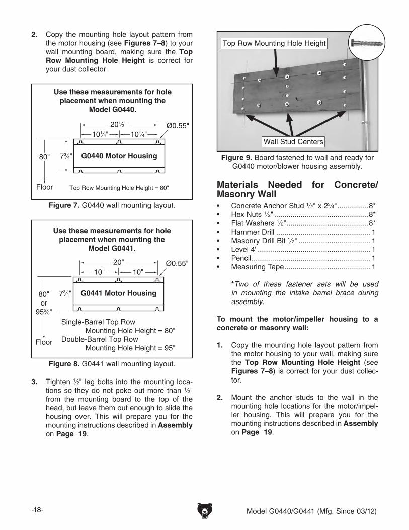
2. Copy the mounting hole layout pattern from the motor housing (see Figures 7–8) to your wall mounting board, making sure the Top Row Mounting Hole Height is correct for your dust collector.
Use these measurements for holeplacement when mounting the
Model G0441.
Single-Barrel Top Row Mounting Hole Height = 80"Double-Barrel Top Row Mounting Hole Height = 95"
20"10"10"
G0441 Motor Housing73⁄4"80"or
955⁄8"
Floor
Ø0.55"
Figure 8. G0441 wall mounting layout.
Use these measurements for holeplacement when mounting the
Model G0440.
Top Row Mounting Hole Height = 80"
201⁄2"101⁄4"
G0440 Motor Housing73⁄4"80"
Floor
Ø0.55"101⁄4"
Figure 7. G0440 wall mounting layout.
3. Tighten 1⁄2" lag bolts into the mounting loca-tions so they do not poke out more than 1⁄2" from the mounting board to the top of the head, but leave them out enough to slide the housing over. This will prepare you for the mounting instructions described in Assembly on Page 19.
Figure 9. Board fastened to wall and ready for G0440 motor/blower housing assembly.
Top Row Mounting Hole Height
Wall Stud Centers
Materials Needed for Concrete/Masonry Wall• Concrete Anchor Stud 1⁄2" x 23⁄4" ...............8*• Hex Nuts 1⁄2" ..............................................8*• Flat Washers 1⁄2" ........................................8*• Hammer Drill .............................................. 1• Masonry Drill Bit 1⁄2" ................................... 1• Level 4' ....................................................... 1• Pencil .......................................................... 1• Measuring Tape .......................................... 1
*Two of these fastener sets will be used in mounting the intake barrel brace during assembly.
To mount the motor/impeller housing to a concrete or masonry wall:
1. Copy the mounting hole layout pattern from the motor housing to your wall, making sure the Top Row Mounting Hole Height (see Figures 7–8) is correct for your dust collec-tor.
2. Mount the anchor studs to the wall in the mounting hole locations for the motor/impel-ler housing. This will prepare you for the mounting instructions described in Assembly on Page 19.

Model G0440/G0441 (Mfg. Since 03/12) -19-
Assembly
To assemble dust collector:
1. With the help of assistants or power lifting equipment, secure the motor/blower housing assembly onto the hardware you mounted in the Wall Mounting section.
2. Attach the 3 x 6mm foam tape to the top of the intake cylinder, as shown in Figure 10.
Figure 10. Foam tape stuck on intake cylinder.
IntakeCylinder
Foam Tape
3. Attach the intake cylinder to the bottom of the housing, as shown in Figure 11, using (4) 5⁄16"-18 x 3⁄4" hex bolts and (4) 5⁄16" flat wash-ers.
Note: Because this part of the dust collector will not be accessible after assembly, con-sider using medium strength thread locking compound on the bolts that secure the intake cylinder to the motor/blower housing assem-bly. This added measure will ensure that the fasteners will not come loose from vibration.
4. Temporarily attach the intake barrel to the housing with a barrel gasket in between, as shown in Figure 12, using (4) 5⁄16"-18 x 3⁄4" hex bolts and (4) 5⁄16" flat washers—and only snug the bolts, rather than fully tighten them.
Figure 12. Securing blower on intake barrel.
Gasket Here
Intake Barrel
Figure 11. Attaching intake cylinder to the bottom of motor housing.
IntakeCylinder
MotorHousing
HEAVY LIFT!Straining or crushing injury may occur from improperly lifting machine or some of its parts. To reduce this risk, get help from other people and use a fork lift (or other lifting equipment) rated for weight of this machine.

-20- Model G0440/G0441 (Mfg. Since 03/12)
5. Place the intake barrel brace in position and mark the location of the mounting holes (shown in Figure 13) with a small pencil, nail, or push pin.
Figure 14. Using tape on wrench in tight spot.
6. Remove the intake barrel you temporar-ily attached in Step 4, drill holes where you marked in Step 5, and loosely install the wall mount brace to the wall with the remaining fasteners from the Wall Mounting proce-dure.
7. Use the (12) 5⁄16"-18 x 3⁄4" hex bolts and (12) 5⁄16" flat washers to re-install the intake bar-rel to the housing with a barrel gasket in between, as shown in Figure 12 on the previ-ous page.
Note: When installing the two bolts above the intake port, use duct tape on the bottom of your wrench to hold the bolts in place, as shown in Figure 14, to start the bolts easier.
Figure 13. Intake barrel brace positioned to mark the mounting holes.
Mounting Hole
Locations
8. Attach the cyclone funnel to the intake barrel with a barrel gasket between them, as shown in Figure 15, using (12) 5⁄16"-18 x 1" hex bolts, (24) 5⁄16" flat washers, and (12) 5⁄16"-18 hex nuts; also secure the wall mounting brace to the lip of the intake barrel/funnel assembly with the same hardware.
Note: At the places where you see 3 holes in a row, only use the center hole for this step. The two outside holes are only designed for use with the optional stand.
Figure 15. Cyclone funnel attached to intake barrel.
Barrel Gasket Here
9. Tighten the wall mounting brace to the wall.
10. Attach the cyclone vacuum tube to the cyclone funnel with (4) 5⁄16"-18 x 3⁄4" hex bolts and (4) 5⁄16" flat washers (see Figure 16).
Figure 16. Cyclone vacuum tube and hose attachment.

Model G0440/G0441 (Mfg. Since 03/12) -21-
11. Attach the outlet port and filter L-braces to the blower housing with the outlet gasket between the outlet port and the housing, as shown in Figures 17–18, using (8) 5⁄16"-18 x 1" hex bolts, (16) 5⁄16" flat washers, and (8) 5⁄16"-18 hex nuts.
Note: On the G0441, one of the braces attaches directly to the housing with the fol-lowing extra hardware: (2) 5⁄16"-18 x 1" hex bolts, (4) 5⁄16" flat washers, and (2) 5⁄16"-18 hex nuts.
Figure 17. Model G0440 outlet port and filter L-braces installed.
12. Mount the filter to the L-braces with the brace gaskets between them, as shown in Figure 19, using (4) 5⁄16"-18 x 3⁄4" hex bolts and (4) 5⁄16" fender washers.
Figure 19. Mounting filters to the braces.
Brace Gasket Here
Figure 18. Model G0441 outlet port and filter L-braces installed.
Outlet Gasket Here
13. Model G0440:
a. Apply the 3 x 15mm foam tape to the edges of the outlet port and the canister adapter, as shown in Figure 20.
Figure 20. Foam tape applied to the outlet port and canister adapter (Model G0440).
FoamTape

-22- Model G0440/G0441 (Mfg. Since 03/12)
b. Connect the gray flexible hose from the outlet port to the canister adapter and secure it in place with the two 7" hose clamps, as shown in Figure 21.
Model G0441:
a. Apply the 3 x 15mm foam tape to the lips of the outlet port, canister adapter, and both ends of the muf-fler, as shown in Figure 22.
Figure 22. Foam tape applied to upper components (Model G0441).
FoamTape
FoamTape
b. Attach the 8" x 5" gray flexible hose between the canister adapter and the muffler with two 8" hose clamps, then attach the 8" x 20" gray flexible hose between the muffler and the outlet port with the remaining two 8" hose clamps (see Figure 23).
Note: It may be necessary to reposition the canister L-braces down one bolt hole or shorten the length of the longer piece of flex-ible hose to accommodate the bend in the hose.
Figure 23. Muffler properly positioned between the two gray flexible hoses (Model G0441).
Muffler
14. Attach the casters to the bottom of the lower collection drum, as shown in Figure 24, using the (4) 3⁄8"-16 hex nuts, (8) 3⁄8" flat washers, and (4) 3⁄8" lock washers included in the box with the casters.
Figure 24. Casters attached to the lower collection drum.
Figure 21. Gray hose properly installed (Model G0440).
HoseClamps

Model G0440/G0441 (Mfg. Since 03/12) -23-
Note—For the Model G0441 Only: If you plan to keep your machine under an 8' ceil-ing, skip Step 15.
15. Model G0441: Connect the upper and lower collection drums together and secure them with the included metal clamp and provided fasteners, as shown in Figure 25.
Figure 25. Installing metal clamp around collection drum.
Fasteners
16. Install the drum latches, as shown in Figure 26, with the (6) #10-24 x 3⁄8" Phillips head screws and (6) #10-24 hex nuts included in the box with the drum latches. Make sure the hex nuts are on the outside of the drum so that they will not snag the plastic collection bag.
Note—For the Model G0441 Only: If you are using the collection drum at full height, use the extra (6) #10-24 Phillips head screws and hex nuts provided to plug the lower latch mounting holes.
Figure 26. Installing drum latches on collector drum.
17. Place the collection drum vacuum ring on the bottom of the collection drum (see Figure 27).
Note: During operation, this ring and the vacuum connection to the cyclone funnel will prevent the collection bag from collapsing.
Figure 27. Inserting collection drum vacuum ring.

-24- Model G0440/G0441 (Mfg. Since 03/12)
18. Insert the rubber seal over the top lip of the collection drum rim. Pay special attention to the direction of the seal, as shown in the Figure 28.
Tip: To keep the seal in place, you can use an adhesive applied to the rubber seal at approximately 1" intervals.
Figure 28. Installing canister seal.
Seal
DrumRim
Optional Adhesive
19. Insert the larger of the plastic collection bags into the collection drum, place the lid on the collection drum and hook the latch over the lid, as shown in Figure 29, then clamp it in place.
Figure 29. Latch hooked over lid for clamping.
20. Move the collector drum under the dust col-lector and connect it to the cyclone funnel with the clear flexible hose and the two 9" hose clamps, as shown in Figure 30.
Figure 30. Drum attached to cyclone funnel with clear 9" hose.
21. Connect the vacuum hose to the cyclone fun-nel and collection drum vacuum tubes with (2) 1 1⁄4" hose clamps (see Figure 31).
Figure 31. Connecting the vacuum hose.

Model G0440/G0441 (Mfg. Since 03/12) -25-
22. Fit the plastic canister collection bag over the bottom of the canister filter and clamp in place with the metal bag clamp, as shown in Figure 32.
Figure 32. Plastic collection bag clamped in place under filter.
BagClamp
23. Mount the switch on the funnel, as shown in Figure 33, with the (2) 5⁄16"-18 x 1" hex bolts, (4) 5⁄16" flat washers, and (2) 5⁄16"-18 hex nuts.
Test Run
Once the assembly is complete, test run your machine to make sure it runs properly and is ready for regular operation.
If, during the test run, you cannot easily locate the source of an unusual noise or vibration, stop using the machine immediately, then review the Troubleshooting on Page 41.
If you still cannot remedy a problem, contact our Tech Support at (570) 546-9663 for assistance.
To test run the machine:
1. Make sure you have read the safety instruc-tions at the beginning of the manual and that the machine is setup properly.
2. Make sure all tools and objects used during setup are cleared away from the machine.
3. Press the ON/OFF button to turn the machine ON.
4. Listen to and watch for abnormal noises or actions. The machine should run smoothly with little or no vibration or rubbing noises.
— Strange or unusual noises should be inves-tigated and corrected before operating the machine further. Always disconnect the machine from power when investigating or correcting potential problems.
5. Press the TIMER button and cycle through each of the times to make sure the lights illu-minate on the switch.
6. Press the TIMER on the remote control and cycle through each of the times in the same manner as Step 5.
7. Press the ON/OFF button on the remote con-trol to make sure it is working properly.
Figure 33. Switch mounted to funnel.

-26- Model G0440/G0441 (Mfg. Since 03/12)
SECTION 4: DESIGNING THE SYSTEM
General Duct Material
You have many choices regarding main line and branch line duct material. For best results, use metal duct for the main line and branch lines, then use short lengths of flexible hose to connect each machine to the branch lines.
Plastic duct is also a popular material for home shops. However, be aware that there is a fire or explosion hazard if plastic duct material is used for dust collection without being grounded against static electrical charge build-up. This topic will be discussed later in this section. Another problem with using plastic is that it is less efficient per foot than metal.
Plastic duct generates static electrical buildup that can cause fire or shock. Properly ground it to reduce this risk.
Plastic Duct
Figure 34. Examples of plastic ducting components.
The popularity of plastic duct is due to the fact that it is an economical and readily available product. It is also simple to assemble and easily sealed against air loss. The primary disadvantage of plastic duct for dust collection is the inherent danger of static electrical build-up.
The Model G0440/G0441 works great as a central system for a small shop or a dedicated dust col-lector for large production machines.
When installing the dust collector be sure to put it in an out of the way location such as a corner or separate room. The dust collector is capable of collecting dust from up to three machines running simultaneously. Grizzly offers a complete line of dust collection accessories for setting up a sta-tionary system. Additionally, Grizzly offers a com-plete guide book entitled Dust Collection Basics.
Whatever system you choose, always make sure there are no open flames or pilot lights in the same room as the dust collector. There is a risk of explosion if dust is dispersed into the air.
Always guard against stat-ic electrical build up by grounding all dust collec-tion lines.

Model G0440/G0441 (Mfg. Since 03/12) -27-
There are a number of options when it comes to metal duct, but metal duct that is specially manu-factured for dust collection is the best choice. When selecting your metal duct, choose high quality metal duct with smooth welded internal seams that will minimize airflow resistance. This type of duct usually connects to other ducts or elbows with a simple, self-sealing clamp, is very quick and easy to assemble, and can be readily dismantled and re-installed. This is espe-cially important if you ever need to change things around in your shop or add more tools.
Avoid inferior metal duct that requires you to cut it to length and snap it together. This type of duct is time consuming to install because it requires you to seal all the seams with silicone and screw the components on the ends with sheet metal screws. Another disadvantage is the rough internal seams and crimped ends that unavoidably increase static pressure loss.
There are also many kinds of pure plastic flexible hose, such as non-perforated drainage type hose and dryer vent hose. Drainage type hose, while being economical, does not quite have the flex-ibility required for dust collection. The inside of the duct is also deeply corrugated and can increase the static pressure loss by as much as 50% over smooth wall duct. Dryer vent hose, while being completely flexible, is non-resistant to abrasion and has a tendency to collapse in a negative pressure system. We DO NOT recommend using dryer vent hose in your dust collection system.
If using flex-hose, you should choose one of the many types that are designed specifically for the movement of solid particles, i.e. dust, grains, and plastics. However, the cost of specifically designed flexible duct can vary greatly. Grizzly offers polyethylene hose, which is well suited for the removal of particulate matter, especially saw-dust, since it is durable and completely flexible. Polyethylene is also very economical and avail-able in a wide variety of diameters and lengths for most applications.
Figure 36. Example of flexible metal duct.
Flexible DuctFlexible hose is generally used for short runs, small shops and at rigid duct-to-tool connections. There are many different types of flex hose on the market today. These are manufactured from materials such as polyethylene, PVC, cloth hose dipped in rubber and even metal, including steel and aluminum.
The superior choice here is metal flex hose that is designed to be flexible, yet be as smooth as pos-sible to reduce static pressure loss.
Metal DuctAdvantages of metal duct is its conductivity and that it does not contribute to static electrical charge build-up. However, static charges are still produced when dust particles strike other dust particles as they move through the duct. Since metal duct is a conductor, it can be grounded quite easily to dissipate any static electrical charges.
Figure 35. Examples of metal pipe and components.

-28- Model G0440/G0441 (Mfg. Since 03/12)
System Design Step 3. Sketch a Basic Duct Layout
Dust Collector
Figure 37. Basic sketch of shop layout.
Figure 38. Efficient duct layout.
Main Line Duct
BranchLine Ducts
GOOD
Dust Collector
Figure 39. Inefficient duct layout.
BAD
Dust Collector
For the next step, sketch how you will connect your machines to the dust collector. Consider these general guidelines for an efficient system:
1. Machines that produce the most saw dust should be placed nearest to the dust collector (i.e. planers and sanders).
2. Ideally, you should design the duct system to have the shortest possible main line and sec-ondary branch ducts. See the figures below for ideas of efficient versus inefficient duct layouts.
Step 1. Decide Who Will DesignFor most small-to-medium sized shops, you can design and build the dust collection system your-self without hiring engineers or consultants. We have included some basic information here to get you started on a basic design.
If you have a large shop or plan to design a com-plicated system, we recommend doing additional research beyond this manual or seeking the help of an expert.
Step 2. Sketch Your Shop LayoutWhen designing a successful dust collection sys-tem, planning is the most important step. In this step, sketch a basic layout of your shop, including space requirements of different machines.
Before you get out your pencil and paper, we rec-ommend you visit our FREE Workshop Planner available on our website at www.grizzly.com.
Our Workshop Planner will allow you to quickly and easily design and print a basic shop layout. Don't worry, non-Grizzly brand machines can be substituted with Grizzly machines for layout pur-poses. Note: After you're finished, make sure to save your layout for later modification.
Your sketch only needs the basic details of the shop layout, similar to the Figure below, includ-ing all your current/planned machines and your planned placement of the dust collector.

Model G0440/G0441 (Mfg. Since 03/12) -29-
3. Directional changes should be kept to a mini-mum. The more directional change fittings you use directly increases the overall resis-tance to airflow.
4. Gradual directional changes are more effi-cient than sudden directional changes (i.e. use the largest corner radius possible when changing hose or pipe direction).
5. Each individual branch line should have a blast gate immediately after the branch to control suction from one machine to another.
6. The simpler the system, the more efficient and less costly it will be.
Step 4. Determine Required CFMsSince each machine produces a different amount of sawdust, the requirements for the minimum amount of CFM to move that sawdust is unique to the machine (for example, a planer produces more sawdust than a table saw). Knowing this required CFM is important to gauging which size of duct to use.
Refer to the Figure below for a close estimation of the airflow each machine requires. Keep in mind that machines that generate the most sawdust should be placed closest to the dust collector. If the machine has multiple dust ports, the total CFM required is the sum of all ports.
Figure 40. Approximate required airflow for machines, based on dust port size.
Machine Dust Port Size
Approximate Required CFM
2" 98
2.5" 150
3" 220
4" 395
5" 614
6" 884
7" 1203
8" 1570
9" 1990
10" 2456
If the machine does not have a built-in dust port, use the following table to determine which size of dust port to install.
Figure 41. Dust port size and quantity per average machine.
Machine Average Dust Port Size
Table Saw ......................................................4"Miter/Radial-Arm Saw ....................................2"Jointer (6" and smaller) .................................4"Jointer (8"-12") ...............................................5"Thickness Planer (13" and smaller) ...............4"Thickness Planer (14"-20") ............................6"Shaper ...........................................................4"Router (mounted to table) ..............................2"Bandsaw ........................................................4"Lathe ..............................................................4"Disc Sander (12" and smaller) .......................2"Disc Sander (13-18") ......................................4"Belt Sander (6" and smaller) .........................2"Belt Sander (7"-9") ........................................3"Edge Sander (6" x 80" and smaller) ..............4"Edge Sander (6" x 80" and larger) ................5"Drum Sander (24" and smaller) ...............2 x 4"Drum Sander (24" and larger) .................4 x 4"Widebelt Sander (18" and smaller) ................5"Widebelt Sander (24"-37" single head) ...2 x 6"Widebelt Sander (24"-51" double head) ..5 x 4"
Figure 42. CFM requirements labeled for each machine.
395
395
614
790395
220
98
Table Saw
Planer/Moulder
MiterSaw
Jointer Sander
PlanerShaper
Dust Collector
Write the required CFM for each machine on your sketch, as shown in the figure below.

-30- Model G0440/G0441 (Mfg. Since 03/12)
The general rule of thumb for a main line duct is that the velocity of the airflow must not fall below 3500 FPM.
For small/medium sized shops, using the inlet size of the dust collector as the main line duct size will usually keep the air velocity above 3500 FPM and, depending on your system, will allow you to keep multiple branches open at one time.
Mark your drawing, as shown in the figure below, but using the inlet size for your dust collector as the main line.
The general rule of thumb for a branch line duct is that the velocity of the airflow must not fall below 4000 FPM.
For small/medium sized shops, using the dust port size from the machine as the branch line duct size will achieve the correct velocity in most appli-cations. However, if the dust port on the machine is smaller than 4", make the branch line 4" and neck the line down right before the dust port.
Note: Systems with powerful dust collectors work better if multiple blast gates are left open. This also allows you to run two machines at once. Experiment with different combinations of blast gates open/closed to find the best results for your system.
Write your determined branch line sizes on your drawing, as shown in the following Figure.
Figure 43. Main line size labeled on sketch.
395
395
614
790395
220
98
Dust Collector
5" 6" 7"
Table Saw
Planer/Moulder
MiterSaw
Jointer Sander
PlanerShaper
The general rule of thumb for a branch line duct is that the velocity of the airflow must not fall below 4000 FPM.
For small/medium sized shops, using the dust port size from the machine as the branch line duct size will achieve the correct velocity in most appli-cations. However, if the dust port on the machine is smaller than 4", make the branch line 4" and neck the line down right before the dust port.
Note: Systems with powerful dust collectors work better if multiple blast gates are left open. This also allows you to run two machines at once. Experiment with different combinations of blast gates open/closed to find the best results for your system.
Write your determined branch line sizes on your drawing, as shown in the following Figure.
Determining Branch Line Duct Size
Figure 44. Branch line duct sizes labeled.
395
395
614
790395
220
98
4"
4"
4" 6"
4" 4" 5"
5" 6" 7"
Table Saw
MiterSaw
Jointer Sander
PlanerShaper
Planer/Moulder
Dust Collector
Plan the drop downs for each machine, using blast gates wherever possible to control airflow.
Planning Drop Downs
To Planer
Blast Gate
Flex Pipe
Rigid Pipe
Rigid Pipe (Main Line)
Elbow
Clamp
Y Branch
Figure 45. Drop down setup.
Determining Main Line Duct Size

Model G0440/G0441 (Mfg. Since 03/12) -31-
Figure 46. Static pressure loss tables.
Duct Dia.
Approximate Static Pressure
Loss Per Foot of Rigid Pipe
Approximate Static Pressure Loss Per Foot of Flex Pipe
Main Lines
at 3500 FPM
Branch Lines
at 4000 FPM
Main Lines
at 3500 FPM
Branch Lines
at 4000 FPM
2" 0.091 0.122 0.35 0.453
2.5" 0.08 0.107 0.306 0.397
3" 0.071 0.094 0.271 0.352
4" 0.057 0.075 0.215 0.28
5" 0.046 0.059 0.172 0.225
6" 0.037 0.047 0.136 0.18
7" 0.029 0.036 0.106 0.141
8" 0.023 0.027 0.08 0.108
9" 0.017 0.019 0.057 0.079
Fitting Dia.
90˚ Elbow
45˚ Elbow
45˚ Wye(Y)
90˚ Wye(Y)
3" 0.47 0.235 0.282 0.188
4" 0.45 0.225 0.375 0.225
5" 0.531 0.266 0.354 0.236
6" 0.564 0.282 0.329 0.235
7" 0.468 0.234 0.324 0.216
8" 0.405 0.203 0.297 0.189
In most small/medium shops it is only necessary to calculate the line with the longest duct length or the most fittings (operating under the assumption that if the line with the highest resistance works, the others will be fine).
To calculate the static pressure of any given line in the system, follow these steps:
1. Make a list of each size duct in the line, including the length, and multiply those num-bers by the static pressure value given in the previous table.
2. List each type of elbow or branch and multiply the quantity (if more than one) by the static pressure loss given in the previous table.
Two Machines on Same Branch Line
Total CFM Branch Line Size
400 4"
500 4"
600 5"
700 5"
800 6"
900 6"
1000 6"
Adding duct work, elbows, branches and any other components to a duct line increases airflow resistance (static pressure loss). This resistance can be minimized by using rigid (smooth) pipe and gradual curves, as opposed to flexible pipe and 90˚ elbows.
To help you think about this resistance, imagine riding a bicycle in a tunnel that is an exact replica of your duct work. If the inside of the tunnel is very bumpy (flexible pipe) and has a lot of sharp turns (90˚ elbows), it will take a lot more effort to travel from one end to the other.
The purpose of calculating the resistance is to determine if it is low enough from the machine to the dust collector to meet the given CFM require-ment for the machine. Use the following tables to calculate the resistance of duct work.
Calculating Duct Resistance
Multiple Dust PortsIf your machine has multiple dust ports, add the total CFM given for each dust port size from the table provided in the earlier subsection, Determine Required CFMs, then find the closest CFM in the table below to determine the correct branch size. Split the branch line just before the dust ports with matching duct sizes.
If two machines will connect to the same branch line and both will operate at the same time, then add the required CFM for each machine together and find the closest total CFM in the table below to determine the correct branch size.
If both machines will never run at the same time, reference the machine with the biggest dust port in the table below and add blast gates after the Y-branch to open/close the line to each machine.

-32- Model G0440/G0441 (Mfg. Since 03/12)
Figure 47. Additional factors affecting static pressure.
Additional Factors Static Pressure
Seasoned (well used)
Dust Collection Filter1"
Entry Loss at Large
Machine Hood2"
Figure 48. Totaling static pressure numbers.
Main Line6" Rigid Pipe (0.037) at 20' ................ 0.740
Branch Line4" Rigid Pipe (0.075) at 10' ................ 0.7504" Flex Pipe (0.28) at 5' ........................ 1.400
Elbows/Branches6" 45˚ Y-Branch ................................ 0.3294" 45˚ Elbow ........................................ 0.225
Additional FactorsSeasoned Filter ................................ 1.000
Total Static Pressure Loss ................ 4.444
4. Total your list as shown in the example below to come up with your overall static pressure loss number for that line.
Note: Always account for a seasoned filter, so you don't end up with a system that only works right when the filter is clean.
Note: When calculating static pressure loss to determine if multiple lines can be left open at the same time, only include the main line numbers once.
3. Add the additional factors from the following-table to your list.
5. Compare the total static pressure loss for that line to the closest CFM given in Figure 50 for your dust collector on Page 34.
Example: A typical Data Sheet Performance Curve is illustrated in Figure 49. Find 4.4 on the Static Pressure axis (the amount of total static pressure loss calculated in Figure 48), then refer to the closest value on the CFM axis—approximately 1120 CFM.
The 1120 CFM for the static pressure loss of the line connected to the router is well above the 220 CFM requirement of that machine.
-6- G0440/G0441/G0443 Cyclone Dust Collectors
G0440 MACHINE DATA SHEET
Customer Service #: (570) 546-9663 • To Order Call: (800) 523-4777 • Fax #: (800) 438-5901
MODEL G04402 HP TWO-STAGE CYCLONE DUST COLLECTOR
©2005 BY GRIZZLY INDUSTRIAL®
Specifications, while deemed accurate, are not guaranteed. 2/2005.
The airflow test probe is located 1.5x duct diameter upstream from the air inlet. Test pipe length is a minimum of 10x duct diameter.
2 HP GRIZZLY DUST COLLECTOR PERFORMANCE RESULTSMax CFM Max SP HP Volts Inlet Impeller1354 10.4 2 HP 220V 7" 14-1/2"
Restrictor Plate (inch)
Dia. 7" Dia. 6"
Dia. 5"
Dia. 4" Dia. 3" Dia.2"
Static Pressure (Inch/H2O)
2.5 3.2 5.1 7.8 9.2 10.0
CFM 1354 1266 1070 829 586 338
Performance Curve2500225020001750150012501000
750500250
00.0 1.0 2.0 3.0 4.0 5.0 6.0 7.0 8.0 9.0 10.0 11.0 12.0 13.0
1354
CFM STATIC PRESSURE (Inch/H2O)
Figure 49. CFM for static pressure loss of line connected to a dust collector & router.
Closest CFM
(1120)
4.4 SP Loss
— If the CFM for your static pressure loss is above the requirement of the machine connected to the end of that branch line, then dust collection will most likely be successful. Congratulations! You've just designed your own dust system. Refer to the Accessories section on Page 36 to start buying the components necessary to make your system a reality.
—If the CFM for your static pressure loss is below the requirement of the machine, then that line will not effectively collect the dust. You must then modify some of the factors in that line to reduce the static pressure loss. Some of the ways to do this include 1) installing larger duct, 2) reducing amount of flexible duct used, 3) increasing machine dust port size, 4) moving machine closer to dust collector to eliminate duct length, and 5) reducing 90˚ elbows or replacing them with 45˚ elbows.

Model G0440/G0441 (Mfg. Since 03/12) -33-
Figure 50. G0440 performance curve chart and data.
CFM
The airflow test probe is located 1.5x duct diameter upstream from the air inlet. Test pipe length is a minimum of 10x duct diameter.
2 HP GRIZZLY DUST COLLECTOR PERFORMANCE RESULTSMax CFM Max SP HP Volts Inlet Impeller1354 10.4 2 HP 220V 7" 14-1/2"
Restrictor Plate Diameter (inch)
7" 6" 5" 4" 3" 2"
Static Pressure (Inch/H2O)
2.5 3.2 5.1 7.8 9.2 10.0
CFM 1354 1266 1070 829 586 338
G0440 Performance Curve2500225020001750150012501000750500250
00.0 1.0 2.0 3.0 4.0 5.0 6.0 7.0 8.0 9.0 10.0 11.0
1354
STATIC PRESSURE (Inch/H2O)
Figure 51. G0441 performance curve chart and data.
The airflow test probe is located 1.5x duct diameter upstream from the air inlet. Test pipe length is a minimum of 10x duct diameter.
2 HP GRIZZLY DUST COLLECTOR PERFORMANCE RESULTSMax CFM Max SP HP Volts Inlet Impeller1654 14.2 3 HP 220V 8" 15-1/2"
Restrictor Plate (inch)
Dia. 8"
Dia. 7"
Dia. 6"
Dia. 5"
Dia. 4"
Dia. 3"
Dia. 2"
Static Pressure (Inch/H2O)
2.0 2.5 4.2 7.2 10.8 12.7 13.8
CFM 1654 1594 1466 1250 884 625 442
G0441 Performance Curve2500225020001750150012501000750500250
01.0 2.0 3.0 4.0 5.0 6.0 7.0 8.0 9.0 10.0 11.0 12.0 13.0
CFM STATIC PRESSURE (Inch/H2O)
1654
Description Model Quantity
6" Rigid Pipe at 20' G7364 4
4" Rigid Pipe at 10' G6162 2
4" Flex Hose at 5' H7215 6
6" 45° Y-Branch G7353 6
4" 45° Elbow G6167 6
Example Materials ListAfter the system is designed, create a materials list of all the items you will need to build your dust collection system. This will make it easy when it comes time to purchase the materials.
Below is an example of some items that might be needed. Refer to Accessories for dust collection components available through grizzly.com.

-34- Model G0440/G0441 (Mfg. Since 03/12)
System Grounding
Since plastic hose is abundant, relatively inex-pensive, easily assembled and air tight, it is a very popular material for conveying dust from woodworking machines to the dust collector. We recommend using flexible hose (flex-hose) to connect the woodworking machine to the dust collector. However, plastic flex-hose and plastic duct are an insulator, and dust particles moving against the walls of the plastic duct create a static electrical build up. This charge will build until it discharges to a ground. If a grounding medium is not available to prevent static electrical build up, the electrical charge will arc to the nearest grounded source. This electrical discharge may cause an explosion and subsequent fire inside the system.
To protect against static electrical build up inside a non-conducting duct, a bare copper wire should be placed inside the duct along its length and grounded to the dust collector. You must also confirm that the dust collector is continuously grounded through the electrical circuit to the elec-tric service panel.
If you connect the dust collector to more than one machine by way of a non-conducting branching duct system and blast gates, the system must still be grounded as mentioned above. We recom-mend inserting a continuous bare copper ground wire inside the entire duct system and attaching the wire to each grounded woodworking machine and dust collector.
Be sure that you extend the bare copper wire down all branches of the system. Do not forget to connect the wires to each other with wire nuts when two branches meet at a “Y” or “T” connec-tion.
Ensure that the entire system is grounded. If using plastic blast gates to direct air flow, the ground-ing wire must be jumped (see the Figure below) around the blast gate without interruption to the grounding system.
We also recommend wrapping the outside of all plastic ducts with bare copper wire to ground the outside of the system against static electrical build up. Wire connections at Y’s and T’s should be made with wire nuts.
Attach the bare ground wire to each stationary woodworking machine and attach to the dust collector frame with a ground screw as shown in the Figure below. Ensure that each machine is continuously grounded to the grounding terminal in your electric service panel.
External Ground Wire
Internal Ground Wire
Flex-Hose
Ground Screw
Figure 53. Flex-hose grounded to machine.
Plastic BlastGate
CopperGround Wire
Metal Duct
Figure 52. Ground jumper wire when using plastic blast gates and metal duct.
Always guard against stat-ic electrical build up by grounding all dust collec-tion lines.
Model G0440/G0441 (Mfg. Since 03/12) -35-
Damage to your eyes, lungs, and ears could result from using this machine without proper protective gear. Always wear safety glasses, a respirator, and hearing protection when operating this machine.
SECTION 5: OPERATIONS
NOTICEIf you have never used this type of machine or equipment before, WE STRONGLY REC-OMMEND that you read books, trade maga-zines, or get formal training before begin-ning any projects. Regardless of the con-tent in this section, Grizzly Industrial will not be held liable for accidents caused by lack of training.
To reduce the risk of serious injury when using this machine, read and understand this entire manual before beginning any operations.
Loose hair, clothing, or jewelry could get caught in machinery and cause serious personal injury. Keep these items away from moving parts at all times to reduce this risk.
Remote Control
The remote control for the Model G0440/G0441 is IR (infrared) rather than RF (radio frequency) to prevent accidental startups by other common RF items, such as garage door openers.
Because this remote system is IR, you must point the remote control directly at the switch to make it operate.
If you plan on placing your dust collector in a dif-ferent room or outside of your shop, you must mount the switch in the shop and wire it through the wall to the dust collector to make use of the remote control.
Operating the Model G0440/G0441 is simple and straightforward. Turn the dust collector ON, then turn the machine ON. When you are finished with the machine operation, turn the machine OFF, then turn the dust collector OFF.
Blast gates can be used at the start of each branch line to control the air flow from the woodworking machine to the dust collector. If a machine is not being used, keep the blast gate closed to maintain higher levels of efficiency throughout the system.
General

-36- Model G0440/G0441 (Mfg. Since 03/12)
SECTION 6: ACCESSORIESACCESSORIES
Some aftermarket accessories can be installed on this machine that could cause it to function improperly, increasing the risk of serious personal injury. To minimize this risk, only install accessories recommended for this machine by Grizzly.
NOTICERefer to the newest copy of the Grizzly Catalog for other accessories available for this machine.
H7499—Stand for G0440H7509—Stand for G0441Mounting your dust collector to a stand expands your layout options, and helps pro-tect the dust collector from getting banged up. Also greatly decreases overall noise and vibration that is an inherent part of wall mounting.
Figure 54. Cyclone mounted on stand.
Figure 56. Rigid Metal Flex Hose.
H7215—4" x 5' Rigid Metal Flex HoseH7216—5" x 5' Rigid Metal Flex HoseH7217—6" x 5' Rigid Metal Flex HoseH7218—7" x 5' Rigid Metal Flex HoseH7219—8" x 5' Rigid Metal Flex HoseThis flex hose provides just enough flexibility to make difficult connections while still keep-ing the inside wall as smooth as possible to minimize static pressure loss.
H5294—4" Metal Duct Machine Addition KitH5296—5" Metal Duct Machine Addition KitH5298—6" Metal Duct Machine Addition KitSave over 20% with this great machine addi-tion kit. Includes: (2) blast gates, (1) machine adapter, (10) pipe clamps, (2) pipe hangers, (2) 5' straight pipes, (2) adjustable nipples, (1) branch, and (1) 60˚ elbow.
Figure 55. Metal Duct Machine Addition Kit.

Model G0440/G0441 (Mfg. Since 03/12) -37-
G6163—4" ClampG7343—5" ClampG7361—6" ClampH5228—7" ClampH5238—8" ClampH5253—9" ClampThese clamps feature lever latches and foam seals, and secure around the rolled ends of fit-tings and pipe.
Figure 57. Dust collection pipe clamps.
G0572—Hanging Air Cleaner w/RemoteUnfortunately, not even the best dust collec-tion systems get all the dust. This is why it is extremely important to have one or two air cleaners to claim the fine dust suspended in the air. This model features a convenient remote control, three speeds, an automatic shutoff timer, and a 2-stage filter system (5 micron outer and 1 micron inner). Easily the best value in its class!
Figure 60. G0572 Hanging Air Cleaner.
G2752—4" Rolling Floor SweepG2753—4" Bench Dust Collection AttachmentG2754—4" Floor Dust Collection AttachmentThese attachments are indispensable for collect-ing dust at machines without a port. The rolling floor sweep is also a convenient way to keep the shop floor or workbench top clean! Designed for use with 4" flexible hose (not included).
Figure 58. Dust collection attachments.
G2752 G2753
G2754
W1039—Universal AdapterThis seven step adapter provides a multitude of dust collection reducing options. Simply cut away unneeded steps with a hacksaw. Outside diameter step sizes include 1", 2", 2.5", 3", 4", 5", and 6". Wall thickness is 1⁄8".
Figure 59. W1039 Universal Adapter.

-38- Model G0440/G0441 (Mfg. Since 03/12)
SECTION 7: MAINTENANCE
Always disconnect power to the machine before performing maintenance. Failure to do this may result in serious person-al injury.
Emptying Drum
Empty the collection drum when it is no more than 3⁄4 full. If the drum is overfilled, dust will be sucked into the inlet cylinder and pass through to the filter.
How quickly the drum fills up is based on the type of work being done at that time.
A machine that produces fine dust, such as a sander or table saw, will slowly fill the drum.
A machine that produces curly shavings, such as a planer or jointer, will quickly fill the drum.
Until you are familiar with long it takes the cyclone to fill the drum, check it regularly to get an idea of how often it needs to be emptied.
Cleaning Filter
Your new cyclone dust collector has a gentle brush system inside the filter for cleaning. This brush system is controlled by the red and black handles shown in Figure 61.
To clean the filter, pull the red handle down all the way, then pull the black handle down and hook it in place.
Always make sure to leave the red handle in the up position to ensure that the brushes return to their proper position and do not restrict the filter.
Figure 61. Brush handles for cleaning the filter.
Hook
Black Handle
Red Handle
Rinsing Filter
For a thorough cleaning, the filter can be removed and rinsed off. However, make sure to clean the filter with the brush system first. Allow the filter to air dry, but never leave the filter in the sun to dry or it could become damaged. Refer to Removing/Replacing Filter on the next page for detailed instructions in removing the canister filter.

Model G0440/G0441 (Mfg. Since 03/12) -39-
Removing/Replacing Filter
The filter inside the canister assemblies can be removed from the assembly so that it can be replaced or rinsed off.
Removing/installing the filter requires removing the canister filter assembly from the dust collec-tor and disassembling it. Follow the instructions below to perform this procedure.
When replacing the filter for the G0440 ask for part number P0440032V2-4. For the G0441, ask for part number P04410032V2-4 from Grizzly at 800-523-4777.
Tools Needed QtyOpen-End Wrench 10mm .................................. 1Wrench or Socket 12mm ................................... 2
To replace the canister filter:
1. DISCONNECT MACHINE FROM POWER!
2. Remove the bag clamp and collection bag from the canister assembly.
3. Pull the black handle all the way down and secure the cable into the handle hook at the bottom of the canister assembly, as shown in Figure 62, to hold it in place during the fol-lowing steps.
4. Remove the canister assembly from the dust collector and place it right-side up on a stable, flat surface.
5. Remove the six hex bolts, hex nuts, and flat washers from the rim of the canister base, as shown in Figure 63.
Figure 62. Black handle cable secured in the handle hook.
BlackHandle
Hook
Figure 63. Removing the hex nuts and flat washers from the rim of the canister base.
CanisterBase
6. With help from another person to steady the canister assembly, turn it upside down and remove the two hex bolts, hex nuts, and flat washers from the cross support (see Figure 64), then remove the canister base from the assembly.
Figure 64. Cross support fasteners.
Remove These

-40- Model G0440/G0441 (Mfg. Since 03/12)
7. Carefully lift the filter out of the canister assembly, as shown in Figure 65.
Figure 65. Removing the filter from the canister assembly.
8. Before re-inserting a filter into the assembly, make sure that the filter brush base is aligned with two of the fastener holes around the base of the assembly (see Figure 66). This will allow the canister base to align with the fastener holes around the brush base.
Figure 66. Filter brush base aligned with assembly fastener holes.
9. Re-insert a filter into the canister assembly.
Note: Make sure the bristles of the brush are straight to ensure efficient cleaning of the filter when needed.
10. Re-attach the canister base in the reverse order that you removed it.
11. Re-attach the canister assembly to the dust collector, then re-install a fresh collection bag with the bag clamp.

Model G0440/G0441 (Mfg. Since 03/12) -41-
Review the troubleshooting and procedures in this section to fix or adjust your machine if a problem devel-ops. If you need replacement parts or you are unsure of your repair skills, then feel free to call our Technical Support at (570) 546-9663.
SECTION 8: SERVICE
Troubleshooting
Symptom Possible Cause Possible SolutionMotor will not start, or it growls on start up.
1. Power supply fuse or circuit breaker has tripped.
2. Toggle switch is broken inside.3. Start capacitor is at fault.4. Motor fan cover is dented.5. Motor is at fault.
1. Disconnect power, and inspect circuit for electrical shorts and repair; replace circuit breaker
2. Disconnect power, and check/replace switch.3. Replace start capacitor.4. Replace motor fan cover (and fan, if damaged).5. Replace motor.
Motor runs slower than normal.
1. Poor electrical connection.
2. Low power source voltage.
3. Motor is at fault.
1. Inspect the power supply for loose, corroded, or overheated electrical connections and repair.
2. Have the power source voltage checked; reduce the length of extension cord.
3. Replace the motor.
Loud, repetitious noise, or excessive vibration coming from dust collector.
1. Dust collector is not on a flat surface and wobbles.
2. Impeller fan is damaged and unbalanced.
3. The motor mounting is loose.4. Impeller is loose on the motor shaft.
5. Motor fan cover is dented, causing the motor fan to hit the cover while spinning.
1. Stabilize the dust collector.
2. Unplug dust collector, and inspect the impeller for dents, bends, loose fins; replace.
3. Re-tighten all fasteners on the dust collector.4. Replace the motor and impeller as a set if the
motor shaft and the impeller hub is damaged.5. Replace motor fan cover.
Dust collector does not adequately collect dust or chips; poor performance.
1. Dust collection drum is full.2. Filter is dirty.3. Restriction in the duct line.
4. The dust collector is too far away from the point of suction, or there are too many sharp bends in the ducting.
5. The lumber is wet and not flowing through the dust lines smoothly.
6. There is a leak in the ducting, or a series of small leaks, or too many open ports.
7. There are not enough open branch lines at one time, thereby causing a velocity drop in the main line.
8. The ducting and ports are incorrectly sized.
9. The machine dust collection design is inadequate.
10. The dust collector is too small for the dust collection system.
1. Empty collection drum.2. Clean filter.3. Remove dust line from dust collector inlet and
unblock the restriction in the duct line. A plumbing snake may be necessary.
4. Relocate the dust collector closer to the point of suction, and rework ducting without sharp bends. Refer to System Design, beginning on Page 27.
5. Process lumber with less than 20% moisture content.
6. Rework the ducting to eliminate all leaks. Close dust ports for lines not being used. Refer to System Design on Page 27 for more solutions.
7. Open 1 or 2 more blast gates to different branch lines to allow the velocity in the main line to increase.
8. Reinstall correctly sized ducts and fittings. Refer to System Design on Page 27 for more solutions.
9. Use a dust collection nozzle on a stand.
10. Install a larger dust collector to power your dust collection system.

-42- Model G0440/G0441 (Mfg. Since 03/12)
These pages are current at the time of printing. However, in the spirit of improvement, we may make chang-es to the electrical systems of future machines. Study this section carefully. If there are differences between your machine and what is shown in this section, call Technical Support at (570) 546-9663 for assistance BEFORE making any changes to the wiring on your machine.
SECTION 9: WIRING
SHOCK HAZARD. Working on wiring that is con-nected to a power source is extremely dangerous. Touching electrified parts will result in personal injury including but not limited to severe burns, electrocution, or death. Disconnect the power from the machine before servicing electrical com-ponents!
MODIFICATIONS. Modifying the wiring beyond what is shown in the diagram may lead to unpre-dictable results, including serious injury or fire. This includes the installation of unapproved after-market parts.
WIRE CONNECTIONS. All connections must be tight to prevent wires from loosening during machine operation. Double-check all wires dis-connected or connected during any wiring task to ensure tight connections.
CIRCUIT REQUIREMENTS. You MUST follow the requirements at the beginning of this man-ual when connecting your machine to a power source.
WIRE/COMPONENT DAMAGE. Damaged wires or components increase the risk of serious per-sonal injury, fire, or machine damage. If you notice that any wires or components are damaged while performing a wiring task, replace those wires or components.
MOTOR WIRING. The motor wiring shown in these diagrams is current at the time of printing but may not match your machine. If you find this to be the case, use the wiring diagram inside the motor junction box.
CAPACITORS/INVERTERS. Some capacitors and power inverters store an electrical charge for up to 10 minutes after being disconnected from the power source. To reduce the risk of being shocked, wait at least this long before working on capacitors.
EXPERIENCING DIFFICULTIES. If you are expe-riencing difficulties understanding the information included in this section, contact our Technical Support at (570) 546-9663.
Wiring Safety Instructions
The photos and diagrams included in this section are best viewed in color. You can view these pages in color at www.grizzly.com.

Model G0440/G0441 (Mfg. Since 03/12) -43-READ ELECTRICAL SAFETY ON PAGE 42!
A1
Gro
und 2T1 6T3 14NO4T2
1L1 5L3 13NO3L2
NHD C-12D
2T1 4T2 6T3
98 97
A2
96
O R
9511 12
13
14
NHD NTH-14 ON/OFFSwitch
A2
OL_NO AC OUT
ACIN
Sta
rtC
apac
itor
300M
FD
125V
AC
Run
Cap
acito
r50
µF25
0VA
C
220V Motor
220V Circuit Board
220V Magnetic Contactor Switch and Overload Relay
Ground
Hot
Hot
DISCONNECTSWITCH
(as recommended)
1-PHASE220 VAC
G0440 Wiring Diagram

-44- Model G0440/G0441 (Mfg. Since 03/12)READ ELECTRICAL SAFETY ON PAGE 42!
A1
Gro
und 2T1 6T3 14NO4T2
1L1 5L3 13NO3L2
NHD C-18D
2T1 4T2 6T3
98 97
A2
96
O R
9521 23
24
25
NHD NTH-25 ON/OFFSwitch
A2
OL_NO AC OUT
ACIN
Sta
rtC
apac
itor
600M
FD
125V
AC
Run
Cap
acito
r60
µF30
0VA
C
220V Motor
220V Circuit Board
220V Magnetic Contactor Switch and Overload Relay
Ground
Hot
Hot
DISCONNECTSWITCH
(as recommended)
1-PHASE220 VAC
G0441 Wiring Diagram
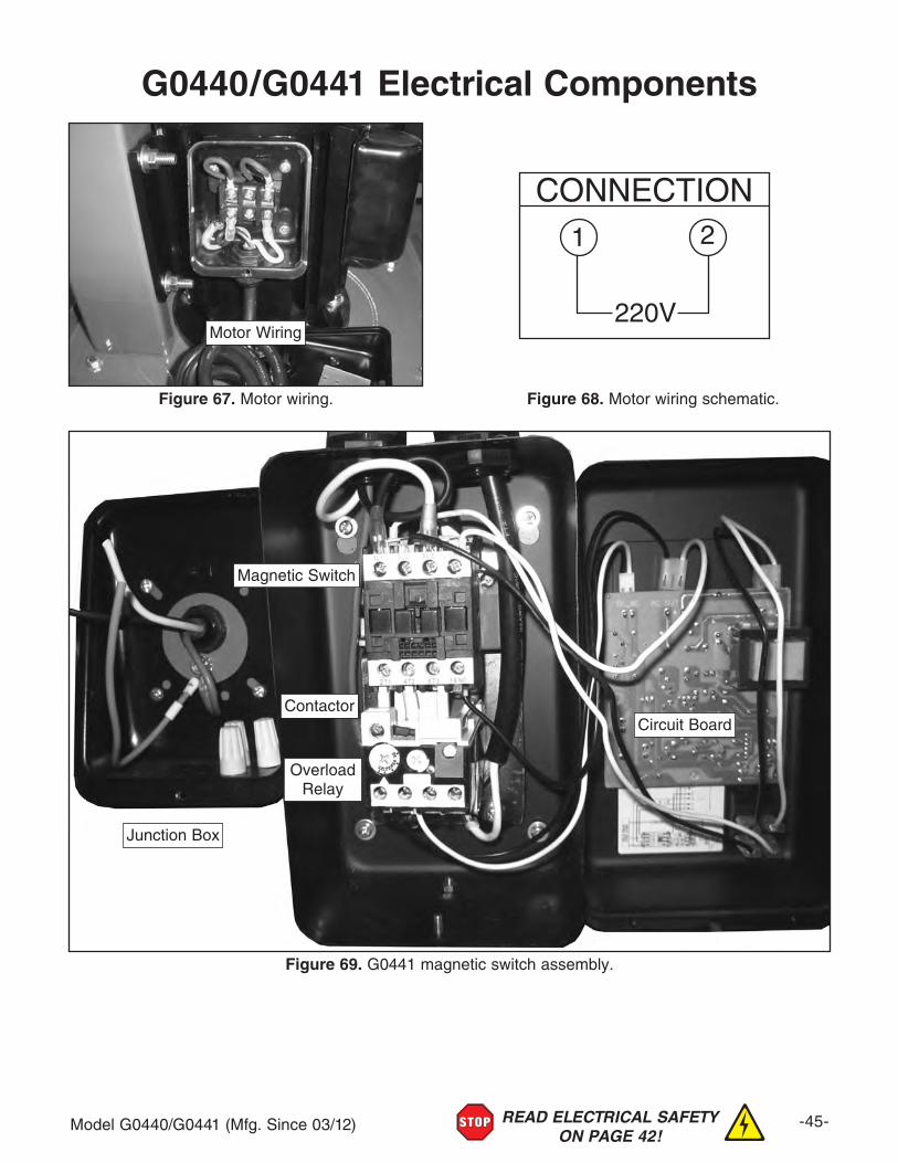
Model G0440/G0441 (Mfg. Since 03/12) -45-READ ELECTRICAL SAFETY ON PAGE 42!
G0440/G0441 Electrical Components
Figure 69. G0441 magnetic switch assembly.
Contactor
Overload Relay
Circuit Board
Magnetic Switch
Junction Box
220V
1 2
CONNECTION
Motor Wiring
Figure 67. Motor wiring. Figure 68. Motor wiring schematic.

-46- Model G0440/G0441 (Mfg. Since 03/12)
11-1
1-2
1-3
1-4 1-5
1-6
2
3V3
4
5
67
8
9
1011
12
13
14A
1516
17
18V2
1920
21 22
23
2425
26
27
28
28-1
29
3031
32V332V3-1
32V2-2
32V2-3
32V2-4
32V2-5
34V2
35 363738
3940
41
42
43
44V2
4546
47
48
49
50
51V2
52V2A
52V253
5455
56
5758
59
60
94
95
61
62V2
63
6465
66
67
68
69
70
71
72V2
73
74
77
78
79
80
81
82
83
84
85
86
8788
89
90
91
92
93
79
2646
6196
32V2-3
59
48
DUTY
Grizzly Cyclone Induction Motor
Connections:
Manufactured for Grizzly in Taiwan
HEATWEIGHT
CLASS
DATE
HZ
SER. NO.
VOLT
OUTPUT
AMP
RPMPHASE
3V3-13V3-2
3V3-3
3V3-4
1-9
1-7
1-10
1-8
SECTION 10: PARTSg
G0440 Main

Model G0440/G0441 (Mfg. Since 03/12) -47-
G0440 Parts ListREF PART # DESCRIPTION REF PART # DESCRIPTION1 P0440001 MOTOR 2HP 220V 1-PH 39 P0440039 BARREL GASKET 584MM DIA.1-1 P0440001-1 MOTOR FAN COVER 40 P0440040 INTAKE BARREL 20"1-2 P0440001-2 MOTOR FAN 41 P0440041 HEX BOLT 5/16-18 X 3/41-3 P0440001-3 CAPACITOR COVER 42 P0440042 FLAT WASHER 5/161-4 P0440001-4 S CAPACITOR 300M 125V 1-3/4 X 3-3/8 43 P0440043 BARREL GASKET 584MM DIA.1-5 P0440001-5 R CAPACITOR 50M 250V 1-5/8 X 3-1/2 44V2 P0440044V2 CYCLONE FUNNEL 20" V2.08.101-6 P0440001-6 JUNCTION BOX 45 P0440045 HEX BOLT 5/16-18 X 11-7 P0440001-7 BALL BEARING 6205ZZ 46 P0440046 FLAT WASHER 5/161-8 P0440001-8 BALL BEARING 6203ZZ 47 P0440047 HEX NUT 5/16-181-9 P0440001-9 CONTACT PLATE 48 P0440048 HOSE CLAMP 9"1-10 P0440001-10 CENTRIFUGAL SWITCH 3450 49 P0440049 CLEAR FLEX PIPE 9" x 200MM2 P0440002 MOTOR CORD 12G 3C 50 P0440050 COLLECTION DRUM LID V2.08.063V3 P0440003V3 REMOTE MAG SWITCH 220V V3.01.12 51V2 P0440051V2 DRUM SEAL TYPE-T 2.1M V2.11.093V3-1 P0440003V3-1 CONTACTOR NHD C-12D 220V 52V2A P0440052V2A COLLECTION DRUM ASSY 35GAL V2.08.103V3-2 P0440003V3-2 OL RELAY NHD NTH-14 11-14A 52V2 P0440052V2 COLLECTION DRUM 35GAL V2.08.103V3-3 P0440003V3-3 CIRCUIT BOARD 220V W/TRANSFORMER 53 P0440053 DRUM LID LATCH ASSEMBLY3V3-4 P0440003V3-4 ON/OFF SWITCH 110V/220V 54 P0440054 PHLP HD SCR 10-24 X 3/84 P0440004 REMOTE CONTROLLER 55 P0440055 HEX NUT 10-245 P0440005 HEX BOLT 3/8-16 X 1-1/2 56 P0440056 CASTER 2"6 P0440006 FLAT WASHER 3/8 57 P0440057 HEX NUT 3/8-167 P0440007 LOCK WASHER 3/8 58 P0440058 LOCK WASHER 3/88 P0440008 HEX NUT 3/8-16 59 P0440059 FLAT WASHER 3/89 P0440009 BLOWER COVER 60 P0440060 HEX BOLT 5/16-18 X 110 P0440010 HEX BOLT 3/8-16 X 1 61 P0440061 FLAT WASHER 5/1611 P0440011 FENDER WASHER 3/8 62V2 P0440062V2 SWITCH MOUNTING BRACKET V2.01.1212 P0440012 LOCK WASHER 3/8 63 P0440063 HEX NUT 5/16-1813 P0440013 HEX NUT 3/8-16 64 P0440064 WALL MOUNTING BRACE14A P0440014A IMPELLER 14-1/2" V2.02.06 65 P0440065 MOTOR SPEC LABEL15 P0440015 IMPELLER FENDER WASHER 3/8 66 P0440066 MOTOR WARNING LABEL16 P0440016 HEX BOLT 3/8-16 X 1 LH 67 P0440067 GLASSES/RESPIRATOR LABEL17 P0440017 FOAM TAPE 3 X 6 X 1600MM 68 P0440068 READ MANUAL LABEL18V2 P0440018V2 BLOWER HOUSING 14.5" IMP V2.02.06 69 P0440069 HANDS/INLET LABEL19 P0440019 FLAT WASHER 5/16 70 P0440070 RETURN RED HANDLE LABEL20 P0440020 HEX BOLT 5/16-18 X 3/4 71 P0440071 ELECTRICITY LABEL21 P0440021 OUTLET GASKET 306 X 226MM 72V2 P0440072V2 MACHINE ID LABEL CSA V2.01.1222 P0440022 OUTLET PORT 73 P0440073 MODEL NO/HP/GRIZZLY LABEL (LARGE)23 P0440023 HEX BOLT 5/16-18 X 1 74 P0440074 MODEL NO/HP/GRIZZLY LABEL (SMALL)24 P0440024 FLAT WASHER 5/16 77 P0440077 EXT TOOTH WASHER 3/825 P0440025 HEX NUT 5/16-18 78 P0440078 MOTOR MOUNT GASKET26 P0440026 HOSE CLAMP 7" 79 P0440079 FOAM TAPE 3 X 15 X 600MM27 P0440027 GRAY FLEX PIPE 7" X 800MM 80 P0440080 CYCLONE VACUUM TUBE28 P0440028 FILTER L-BRACE (LH) 81 P0440081 FLAT WASHER 5/1628-1 P0440028-1 BRACE GASKET 155 X 37MM 82 P0440082 HEX BOLT 5/16-18 X 3/429 P0440029 FILTER L-BRACE (RH) 83 P0440083 TUBE PLUG 1-1/4"30 P0440030 HEX BOLT 5/16-18 X 3/4 84 P0440084 FOAM TAPE 3 X 6 X 300MM31 P0440031 FLAT WASHER 5/16 85 P0440085 VACUUM HOSE 1-1/4" X 98"32V3 P0440032V3 CANISTER ASSEMBLY (BEIGE) V3.07.12 86 P0440086 COLLECTION DRUM VACUUM TUBE32V3-1 P0440032V3-1 CANISTER CAGE ASSY (BEIGE) V3.07.12 87 P0440087 FLAT WASHER 5/1632V2-2 P0440032V2-2 FOAM TAPE 3 X 25 X 1400MM V2.11.09 88 P0440088 HEX BOLT 5/16-18 X 3/432V2-3 P0440032V2-3 FOAM TAPE 3 X 35 X 1255MM V2.11.09 89 P0440089 HOSE CLAMP 1-1/4"32V2-4 P0440032V2-4 CAN FILTER 386MM W/FOAM TAPE V2.11.09 90 P0440090 TUBE PLUG 1-1/4"32V2-5 P0440032V2-5 BAG CLAMP 445MM V2.11.09 91 P0440091 FOAM TAPE 3 X 6 X 300MM34V2 P0440034V2 PLASTIC BAG 470 X 600MM V2.11.09 92 P0440092 COLLECTION DRUM VACUUM RING35 P0440035 FOAM TAPE 3 X 6 X 1600MM 93 P0440093 DRUM COLLECTION BAG 640 X 1000MM36 P0440036 INTAKE CYLINDER 10" 94 P0440094 JUNCTION BOX37 P0440037 FLAT WASHER 5/16 95 P0440095 JUNCTION BOX CORD 12G 3C 12"38 P0440038 HEX BOLT 5/16-18 X 3/4 96 P0440096 GROUNDING WIRE 12G 6" (GREEN)

-48- Model G0440/G0441 (Mfg. Since 03/12)
G0441 Main
71
72
73
74
75
76
77
78V2
DUTY
Grizzly Cyclone Induction Motor
Connections:
Manufactured for Grizzly in Taiwan
HEATWEIGHT
CLASS
DATE
HZ
SER. NO.
VOLT
OUTPUT
AMP
RPMPHASE
79
80
1
2
3V3
4
5
67
8
9
1011
12
13
14A1516
17
18A
1920
21
22
232425
2627A-1
27A-228
28-1
29
3031
32V3
32V3-1
32V2-2
32V2-3
32V2-4
32V2-5
34V2
35 36
37
38
3940
41
42
43
44V2
4546
47
48
49
50
51V3
52
53V2
5455
5657
5859
6061
62
6364
65
67
68V2
69
70
83
84
85
86
100
101
102103
104
105
106
107 108
109
110 111
112
113
114
26
26
85
26
464685
32V2-3
4853V2A
66
94
95
96
3V3-13V3-2
3V3-3
3V3-4
1-1
1-2
1-3
1-4 1-5
1-6
1-9
1-7
1-10
1-8

Model G0440/G0441 (Mfg. Since 03/12) -49-
G0441 Parts ListREF PART # DESCRIPTION REF PART # DESCRIPTION1 P0441001 MOTOR 3HP 220V 1-PH 43 P0441043 BARREL GASKET 584MM DIA.1-1 P0441001-1 MOTOR FAN COVER 44V2 P0441044V2 CYCLONE FUNNEL 20" V2.08.101-2 P0441001-2 MOTOR FAN 45 P0441045 HEX BOLT 5/16-18 X 11-3 P0441001-3 CAPACITOR COVER 46 P0441046 FLAT WASHER 5/161-4 P0441001-4 S CAPACITOR 600M 125V 1-3/4 X 3-3/4 47 P0441047 HEX NUT 5/16-181-5 P0441001-5 R CAPACITOR 60M 300V 1-5/8 X 3-1/2 48 P0441048 HOSE CLAMP 9"1-6 P0441001-6 JUNCTION BOX 49 P0441049 CLEAR FLEX PIPE 9" X 340MM1-7 P0441001-7 BALL BEARING 6205ZZ 50 P0441050 COLLECTION DRUM LID V2.08.061-8 P0441001-8 BALL BEARING 6203ZZ 51V3 P0441051V3 DRUM SEAL TYPE-R 2M V3.01.121-9 P0441001-9 CONTACT PLATE 52 P0441052 UPPER DRUM 25GAL1-10 P0441001-10 CENTRIFUGAL SWITCH 3450 53V2A P0441053V2A COLLECTION DRUM ASSY 55GAL V2.11.092 P0441002 MOTOR CORD 12G 3C 53V2 P0441053V2 COLLECTION DRUM 35GAL V2.08.103V3 P0441003V3 REMOTE MAG SWITCH 220V V3.01.12 54 P0441054 DRUM CLAMP3V3-1 P0441003V3-1 CONTACTOR NHD C-18D 220V 55 P0441055 HEX BOLT 5/16-18 X 33V3-2 P0441003V3-2 OL RELAY NHD NTH-25 21–25A 56 P0441056 HEX NUT 5/16-183V3-3 P0441003V3-3 CIRCUIT BOARD 220V W/TRANSFORMER 57 P0441057 DRUM LID LATCH ASSEMBLY3V3-4 P0441003V3-4 ON/OFF SWITCH 110/220V 58 P0441058 PHLP HD SCR 10-24 X 3/84 P0441004 REMOTE CONTROLLER 59 P0441059 HEX NUT 10-245 P0441005 HEX BOLT 3/8-16 X 1-1/2 60 P0441060 PHLP HD SCR 10-24 X 3/86 P0441006 FLAT WASHER 3/8 61 P0441061 HEX NUT 10-247 P0441007 LOCK WASHER 3/8 62 P0441062 CASTER 2"8 P0441008 HEX NUT 3/8-16 63 P0441063 HEX NUT 3/8-169 P0441009 BLOWER COVER 64 P0441064 LOCK WASHER 3/810 P0441010 HEX BOLT 3/8-16 X 1-1/2 65 P0441065 FLAT WASHER 3/811 P0441011 FLAT WASHER 3/8 66 P0441066 HEX BOLT 5/16-18 X 112 P0441012 LOCK WASHER 3/8 67 P0441067 FLAT WASHER 5/1613 P0441013 HEX NUT 3/8-16 68V2 P0441068V2 SWITCH MOUNTING BRACKET V2.01.1214A P0441014A IMPELLER 15-1/2" V2.02.06 69 P0441069 HEX NUT 5/16-1815 P0441015 IMPELLER FENDER WASHER 3/8 70 P0441070 WALL MOUNT BRACKET16 P0441016 HEX BOLT 3/8-16 X 1 LH 71 P0441071 MOTOR SPEC LABEL17 P0441017 FOAM TAPE 3 X 6 X 1600MM 72 P0441072 MOTOR WARNING LABEL18A P0441018A BLOWER HOUSING 15-1/2" IMP V2.02.06 73 P0441073 GLASSES/RESPIRATOR LABEL19 P0441019 FLAT WASHER 5/16 74 P0441074 READ MANUAL LABEL20 P0441020 HEX BOLT 5/16-18 X 3/4 75 P0441075 HANDS/INLET LABEL21 P0441021 OUTLET GASKET 326 X 226MM 76 P0441076 RETURN RED HANDLE LABEL22 P0441022 OUTLET PORT 77 P0441077 ELECTRICITY LABEL23 P0441023 HEX BOLT 5/16-18 X 1 78V2 P0441078V2 MACHINE ID LABEL CSA V2.01.1224 P0441024 FLAT WASHER 5/16 79 P0441079 MODEL NO/HP/GRIZZLY LABEL (LARGE)25 P0441025 HEX NUT 5/16-18 80 P0441080 MODEL NO/HP/GRIZZLY LABEL (SMALL)26 P0441026 HOSE CLAMP 8" 83 P0441083 MUFFLER 8"27A-1 P0441027A-1 GREY FLEX PIPE 8" X 500MM V2.04.08 84 P0441084 EXT TOOTH WASHER 3/827A-2 P0441027A-2 GREY FLEX PIPE 8" X 120MM V2.04.08 85 P0441085 FOAM TAPE 3 X 15 X 700MM28 P0441028 FILTER L-BRACE (RH) 86 P0441086 MOTOR MOUNT GASKET28-1 P0441028-1 BRACE GASKET 240 X 32MM 94 P0441094 JUNCTION BOX29 P0441029 FILTER L-BRACE (LH) 95 P0441095 JUNCTION BOX CORD 12G 3C 12"30 P0441030 HEX BOLT 5/16-18 X 3/4 96 P0441096 GROUNDING WIRE 12G 6" (GREEN)31 P0441031 FLAT WASHER 5/16 100 P0441100 COLLECTION DRUM EXT KIT32V3 P0441032V3 CANISTER ASSEMBLY (BEIGE) V3.07.12 101 P0441101 CYCLONE VACUUM TUBE32V3-1 P0441032V3-1 CANISTER CAGE ASSY (BEIGE) V3.07.12 102 P0441102 FLAT WASHER 5/1632V2-2 P0441032V2-2 FOAM TAPE 3 X 25 X 1400MM V2.11.09 103 P0441103 HEX BOLT 5/16-18 X 3/432V2-3 P0441032V2-3 FOAM TAPE 38 X 35 X 1460MM V2.11.09 104 P0441104 TUBE PLUG 1-1/4"32V2-4 P0441032V2-4 CANISTER FILTER 486MM V2.11.09 105 P0441105 FOAM TAPE 3 X 6 X 300MM32V2-5 P0441032V2-5 BAG CLAMP 545MM V2.11.09 106 P0441106 VACUUM HOSE 1-1/4" X 98"34V2 P0441034V2 PLASTIC BAG 570 X 600MM V2.11.09 107 P0441107 COLLECTION DRUM VACUUM TUBE35 P0441035 FOAM TAPE 3 X 6 X 1600MM 108 P0441108 FLAT WASHER 5/1636 P0441036 INTAKE CYCLINDER 10" 109 P0441109 HEX BOLT 5/16-18 X 3/437 P0441037 HEX BOLT 5/16-18 X 3/4 110 P0441110 HOSE CLAMP 1-1/4"38 P0441038 FLAT WASHER 5/16 111 P0441111 TUBE PLUG 1-1/4"39 P0441039 BARREL GASKET 584MM DIA. 112 P0441112 FOAM TAPE 3 X 6 X 300MM40 P0441040 INTAKE BARREL 20" 113 P0441113 COLLECTION DRUM VACUUM RING41 P0441041 HEX BOLT 5/16-18 X 3/4 114 P0441114 DRUM COLLECTION BAG 640 X 1200MM42 P0441042 FLAT WASHER 5/16

-50- Model G0440/G0441 (Mfg. Since 03/12)

CU
T A
LON
G D
OT
TE
D L
INE
Name _____________________________________________________________________________
Street _____________________________________________________________________________
City _______________________ State _________________________ Zip _____________________
Phone # ____________________ Email _________________________________________________
Model # ____________________ Order # _______________________ Serial # __________________
WARRANTY CARD
The following information is given on a voluntary basis. It will be used for marketing purposes to help us develop better products and services. Of course, all information is strictly confidential.
1. How did you learn about us? ____ Advertisement ____ Friend ____ Catalog ____ Card Deck ____ Website ____ Other:
2. Which of the following magazines do you subscribe to?
3. What is your annual household income? ____ $20,000-$29,000 ____ $30,000-$39,000 ____ $40,000-$49,000 ____ $50,000-$59,000 ____ $60,000-$69,000 ____ $70,000+
4. What is your age group? ____ 20-29 ____ 30-39 ____ 40-49 ____ 50-59 ____ 60-69 ____ 70+
5. How long have you been a woodworker/metalworker? ____ 0-2 Years ____ 2-8 Years ____ 8-20 Years ____20+ Years
6. How many of your machines or tools are Grizzly? ____ 0-2 ____ 3-5 ____ 6-9 ____10+
7. Do you think your machine represents a good value? _____Yes _____No
8. Would you recommend Grizzly Industrial to a friend? _____Yes _____No
9. Would you allow us to use your name as a reference for Grizzly customers in your area? Note: We never use names more than 3 times. _____Yes _____No
10. Comments: _____________________________________________________________________
_________________________________________________________________________________
_________________________________________________________________________________
_________________________________________________________________________________
____ Cabinetmaker & FDM____ Family Handyman____ Hand Loader____ Handy____ Home Shop Machinist____ Journal of Light Cont.____ Live Steam____ Model Airplane News____ Old House Journal____ Popular Mechanics
____ Popular Science____ Popular Woodworking____ Precision Shooter____ Projects in Metal____ RC Modeler____ Rifle____ Shop Notes____ Shotgun News____ Today’s Homeowner____ Wood
____ Wooden Boat____ Woodshop News____ Woodsmith____ Woodwork____ Woodworker West____ Woodworker’s Journal____ Other:

TAPE ALONG EDGES--PLEASE DO NOT STAPLE
FOLD ALONG DOTTED LINE
FOLD ALONG DOTTED LINE
GRIZZLY INDUSTRIAL, INC.P.O. BOX 2069BELLINGHAM, WA 98227-2069
PlaceStampHere
Name_______________________________
Street_______________________________
City______________State______Zip______
Send a Grizzly Catalog to a friend:

WARRANTY AND RETURNS
Grizzly Industrial, Inc. warrants every product it sells for a period of 1 year to the original purchaser from the date of purchase. This warranty does not apply to defects due directly or indirectly to misuse, abuse, negligence, accidents, repairs or alterations or lack of maintenance. This is Grizzly’s sole written warranty and any and all warranties that may be implied by law, including any merchantability or fitness, for any par-ticular purpose, are hereby limited to the duration of this written warranty. We do not warrant or represent that the merchandise complies with the provisions of any law or acts unless the manufacturer so warrants. In no event shall Grizzly’s liability under this warranty exceed the purchase price paid for the product and any legal actions brought against Grizzly shall be tried in the State of Washington, County of Whatcom.
We shall in no event be liable for death, injuries to persons or property or for incidental, contingent, special, or consequential damages arising from the use of our products.
To take advantage of this warranty, contact us by mail or phone and give us all the details. We will then issue you a “Return Number,’’ which must be clearly posted on the outside as well as the inside of the carton. We will not accept any item back without this number. Proof of purchase must accompany the merchandise.
The manufacturers reserve the right to change specifications at any time because they constantly strive to achieve better quality equipment. We make every effort to ensure that our products meet high quality and durability standards and we hope you never need to use this warranty.
Please feel free to write or call us if you have any questions about the machine or the manual.
Thank you again for your business and continued support. We hope to serve you again soon.
WARRANTY AND RETURNS