Model 8180-RE210A SINGLE CH. TELEMETRY - … 8180-RE210A SINGLE CH. TELEMETRY - THERMOCOUPLE INPUT...
29
Model 8180-RE210A SINGLE CH. TELEMETRY - THERMOCOUPLE INPUT Installation and Operating Manual For assistance with the operation of this product, contact PCB Piezotronics, Inc. Toll-free: 800-828-8840 24-hour SensorLine: 716-684-0001 Fax: 716-684-0987 E-mail: [email protected] Web: www.pcb.com
Transcript of Model 8180-RE210A SINGLE CH. TELEMETRY - … 8180-RE210A SINGLE CH. TELEMETRY - THERMOCOUPLE INPUT...

Model 8180-RE210A
SINGLE CH. TELEMETRY - THERMOCOUPLE INPUT
Installation and Operating Manual
For assistance with the operation of this product,contact PCB Piezotronics, Inc.
Toll-free: 800-828-884024-hour SensorLine: 716-684-0001
Fax: 716-684-0987E-mail: [email protected]: www.pcb.com
The information contained in this document supersedes all similar information that
may be found elsewhere in this manual. Total Customer Satisfaction – PCB Piezotronics guarantees Total Customer Satisfaction. If, at any time, for any reason, you are not completely satisfied with any PCB product, PCB will repair, replace, or exchange it at no charge. You may also choose to have your purchase price refunded in lieu of the repair, replacement, or exchange of the product. Service – Due to the sophisticated nature of the sensors and associated instrumentation provided by PCB Piezotronics, user servicing or repair is not recommended and, if attempted, may void the factory warranty. Routine maintenance, such as the cleaning of electrical connectors, housings, and mounting surfaces with solutions and techniques that will not harm the physical material of construction, is acceptable. Caution should be observed to insure that liquids are not permitted to migrate into devices that are not hermetically sealed. Such devices should only be wiped with a dampened cloth and never submerged or have liquids poured upon them. Repair – In the event that equipment becomes damaged or ceases to operate, arrangements should be made to return the equipment to PCB Piezotronics for repair. User servicing or repair is not recommended and, if attempted, may void the factory warranty.
Calibration – Routine calibration of sensors and associated instrumentation is recommended as this helps build confidence in measurement accuracy and acquired data. Equipment calibration cycles are typically established by the users own quality regimen. When in doubt about a calibration cycle, a good “rule of thumb” is to recalibrate on an annual basis. It is also good practice to recalibrate after exposure to any severe temperature extreme, shock, load, or other environmental influence, or prior to any critical test. PCB Piezotronics maintains an ISO- 9001 certified metrology laboratory and offers calibration services, which are accredited by A2LA to ISO/IEC 17025, with full traceability to SI through N.I.S.T. In addition to the normally supplied calibration, special testing is also available, such as: sensitivity at elevated or cryogenic temperatures, phase response, extended high or low frequency response, extended range, leak testing, hydrostatic pressure testing, and others. For information on standard recalibration services or special testing, contact your local PCB Piezotronics distributor, sales representative, or factory customer service representative. Returning Equipment – Following these procedures will insure that your returned materials are handled in the most expedient manner. Before
Warranty, Service, Repair, and
Return Policies and Instructions
returning any equipment to PCB Piezotronics, contact your local distributor, sales representative, or factory customer service representative to obtain a Return Warranty, Service, Repair, and Return Policies and Instructions Materials Authorization (RMA) Number. This RMA number should be clearly marked on the outside of all package(s) and on the packing list(s) accompanying the shipment. A detailed account of the nature of the problem(s) being experienced with the equipment should also be included inside the package(s) containing any returned materials. A Purchase Order, included with the returned materials, will expedite the turn-around of serviced equipment. It is recommended to include authorization on the Purchase Order for PCB to proceed with any repairs, as long as they do not exceed 50% of the replacement cost of the returned item(s). PCB will provide a price quotation or replacement recommendation for any item whose repair costs would exceed 50% of replacement cost, or any item that is not economically feasible to repair. For routine calibration services, the Purchase Order should include authorization to proceed and return at current pricing, which can be obtained from a factory customer service representative. Warranty – All equipment and repair services provided by PCB Piezotronics, Inc. are covered by a limited warranty against defective material and workmanship for a period of one year from date of original purchase. Contact
PCB for a complete statement of our warranty. Expendable items, such as batteries and mounting hardware, are not covered by warranty. Mechanical damage to equipment due to improper use is not covered by warranty. Electronic circuitry failure caused by the introduction of unregulated or improper excitation power or electrostatic discharge is not covered by warranty. Contact Information – International customers should direct all inquiries to their local distributor or sales office. A complete list of distributors and offices can be found at www.pcb.com. Customers within the United States may contact their local sales representative or a factory customer service representative. A complete list of sales representatives can be found at www.pcb.com. Toll-free telephone numbers for a factory customer service representative, in the division responsible for this product, can be found on the title page at the front of this manual. Our ship to address and general contact numbers are: PCB Piezotronics, Inc. 3425 Walden Ave. Depew, NY14043 USA Toll-free: (800) 828-8840 24-hour SensorLineSM: (716) 684-0001 Website: www.pcb.com
E-mail: [email protected]
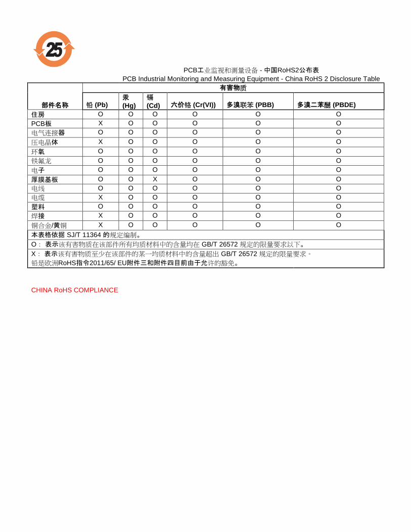
PCB工业监视和测量设备 - 中国RoHS2公布表
PCB Industrial Monitoring and Measuring Equipment - China RoHS 2 Disclosure Table
部件名称
有害物质
铅 (Pb) 汞
(Hg)
镉
(Cd) 六价铬 (Cr(VI)) 多溴联苯 (PBB) 多溴二苯醚 (PBDE)
住房 O O O O O O
PCB板 X O O O O O
电气连接器 O O O O O O
压电晶体 X O O O O O
环氧 O O O O O O
铁氟龙 O O O O O O
电子 O O O O O O
厚膜基板 O O X O O O
电线 O O O O O O
电缆 X O O O O O
塑料 O O O O O O
焊接 X O O O O O
铜合金/黄铜 X O O O O O
本表格依据 SJ/T 11364 的规定编制。
O: 表示该有害物质在该部件所有均质材料中的含量均在 GB/T 26572 规定的限量要求以下。
X: 表示该有害物质至少在该部件的某一均质材料中的含量超出 GB/T 26572 规定的限量要求。
铅是欧洲RoHS指令2011/65/ EU附件三和附件四目前由于允许的豁免。
CHINA RoHS COMPLIANCE
DOCUMENT NUMBER: 21354 DOCUMENT REVISION: C ECN: 45605
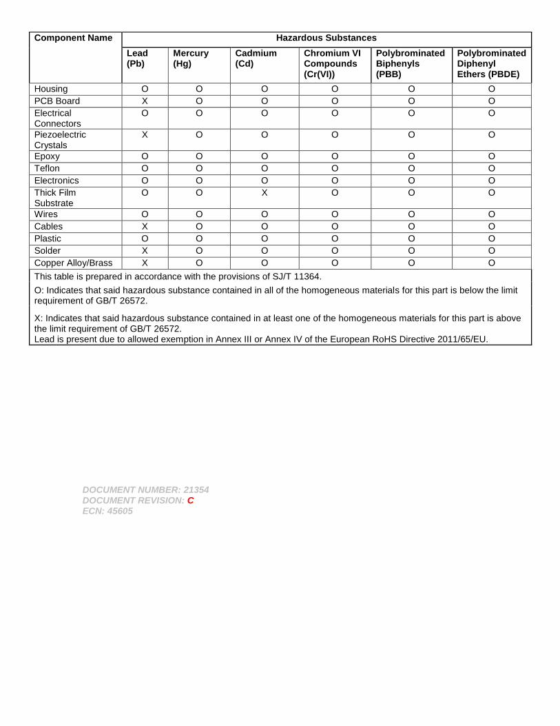
Component Name Hazardous Substances
Lead (Pb)
Mercury (Hg)
Cadmium (Cd)
Chromium VI Compounds (Cr(VI))
Polybrominated Biphenyls (PBB)
Polybrominated Diphenyl Ethers (PBDE)
Housing O O O O O O
PCB Board X O O O O O
Electrical Connectors
O O O O O O
Piezoelectric Crystals
X O O O O O
Epoxy O O O O O O
Teflon O O O O O O
Electronics O O O O O O
Thick Film Substrate
O O X O O O
Wires O O O O O O
Cables X O O O O O
Plastic O O O O O O
Solder X O O O O O
Copper Alloy/Brass X O O O O O
This table is prepared in accordance with the provisions of SJ/T 11364.
O: Indicates that said hazardous substance contained in all of the homogeneous materials for this part is below the limit requirement of GB/T 26572.
X: Indicates that said hazardous substance contained in at least one of the homogeneous materials for this part is above the limit requirement of GB/T 26572. Lead is present due to allowed exemption in Annex III or Annex IV of the European RoHS Directive 2011/65/EU.
Model Number
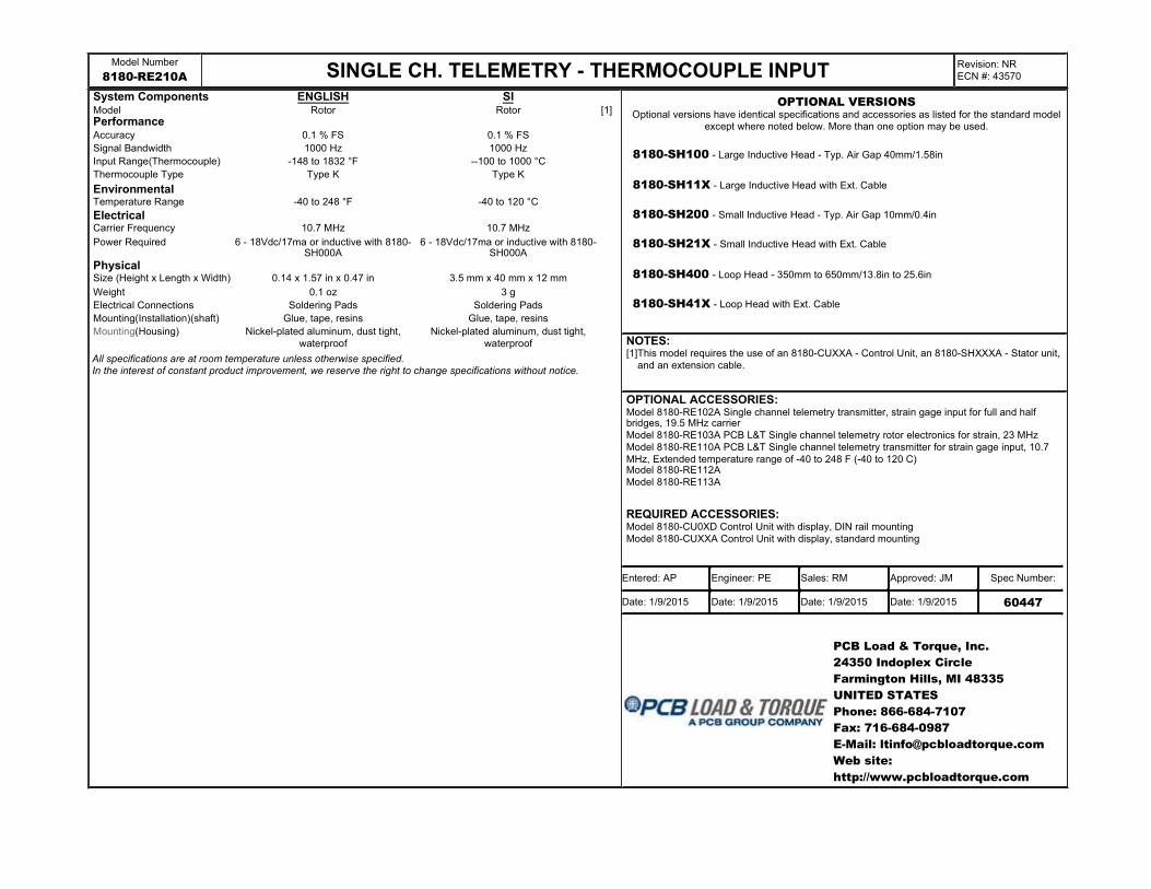
8180-RE210A SINGLE CH. TELEMETRY - THERMOCOUPLE INPUTRevision: NR
ECN #: 43570
System Components ENGLISH SI Model Rotor Rotor [1]PerformanceAccuracy 0.1 % FS 0.1 % FS
Signal Bandwidth 1000 Hz 1000 Hz
Input Range(Thermocouple) -148 to 1832 °F --100 to 1000 °C
Thermocouple Type Type K Type K
EnvironmentalTemperature Range -40 to 248 °F -40 to 120 °C
ElectricalCarrier Frequency 10.7 MHz 10.7 MHz
Power Required 6 - 18Vdc/17ma or inductive with 8180-SH000A
6 - 18Vdc/17ma or inductive with 8180-SH000A
PhysicalSize (Height x Length x Width) 0.14 x 1.57 in x 0.47 in 3.5 mm x 40 mm x 12 mm
Weight 0.1 oz 3 g
Electrical Connections Soldering Pads Soldering Pads
Mounting(Installation)(shaft) Glue, tape, resins Glue, tape, resins
Mounting(Housing) Nickel-plated aluminum, dust tight,
waterproof
Nickel-plated aluminum, dust tight,
waterproof
All specifications are at room temperature unless otherwise specified.
In the interest of constant product improvement, we reserve the right to change specifications without notice.
8180-SH100 - Large Inductive Head - Typ. Air Gap 40mm/1.58in
8180-SH11X - Large Inductive Head with Ext. Cable
8180-SH200 - Small Inductive Head - Typ. Air Gap 10mm/0.4in
8180-SH21X - Small Inductive Head with Ext. Cable
8180-SH400 - Loop Head - 350mm to 650mm/13.8in to 25.6in
8180-SH41X - Loop Head with Ext. Cable
NOTES:[1]This model requires the use of an 8180-CUXXA - Control Unit, an 8180-SHXXXA - Stator unit,
and an extension cable.
OPTIONAL ACCESSORIES: Model 8180-RE102A Single channel telemetry transmitter, strain gage input for full and half bridges, 19.5 MHz carrier
Model 8180-RE103A PCB L&T Single channel telemetry rotor electronics for strain, 23 MHz
Model 8180-RE110A PCB L&T Single channel telemetry transmitter for strain gage input, 10.7
MHz, Extended temperature range of -40 to 248 F (-40 to 120 C)Model 8180-RE112A
Model 8180-RE113A
REQUIRED ACCESSORIES: Model 8180-CU0XD Control Unit with display, DIN rail mounting
Model 8180-CUXXA Control Unit with display, standard mounting
PCB Load & Torque, Inc.
24350 Indoplex Circle
Farmington Hills, MI 48335
UNITED STATES
Phone: 866-684-7107
Fax: 716-684-0987
E-Mail: [email protected]
Web site:
http://www.pcbloadtorque.com
OPTIONAL VERSIONSOptional versions have identical specifications and accessories as listed for the standard model
except where noted below. More than one option may be used.
Entered: AP Engineer: PE Sales: RM Approved: JM Spec Number:
Date: 1/9/2015 Date: 1/9/2015 Date: 1/9/2015 Date: 1/9/2015 60447
1
1
2
2
A A
B B
DWG. NO.
SCALE: SHEET
DRAWN CHECKED ENGINEER
TITLE
UNLESS OTHERWISE SPECIFIED TOLERANCES ARE:
DIMENSIONS IN MILLIMETERS[ IN BRACKETS ]
ANGLES ` .5 DEGREES
24350 Indoplex Circle, Farmington Hills,MI 48335
(248) 888-8260 E-MAIL: [email protected]
DIMENSIONS IN INCHES
ANGLES ` .5 DEGREES
FILLETS AND RADII
.015 MAX
FILLETS AND RADII
0.38 MAX
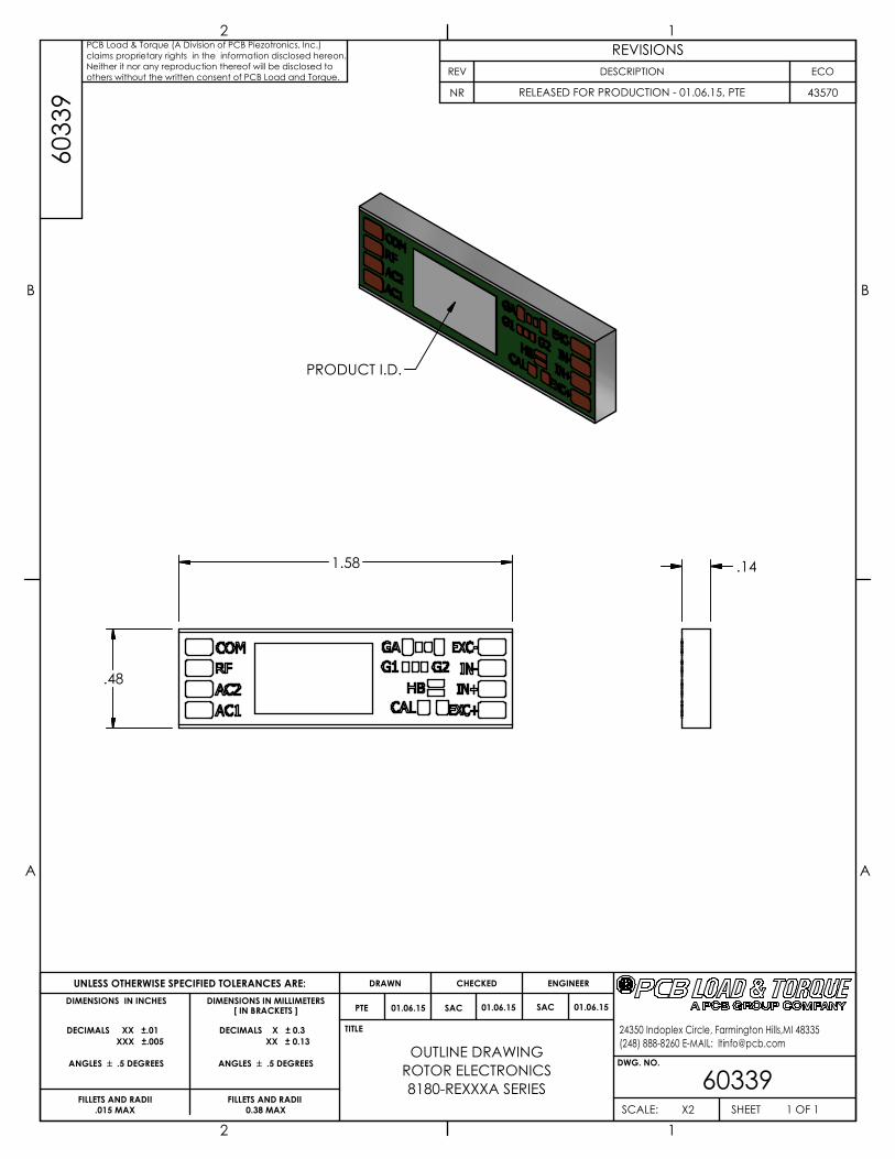
OUTLINE DRAWING
603391 OF 1X2
ROTOR ELECTRONICS
8180-REXXXA SERIES
SAC 01.06.15
DECIMALS XX ±.01
XXX ±.005
DECIMALS X ± 0.3
XX ± 0.13
60
33
9PCB Load & Torque (A Division of PCB Piezotronics, Inc.)
claims proprietary rights in the information disclosed hereon.
Neither it nor any reproduction thereof will be disclosed to
others without the written consent of PCB Load and Torque.
.141.58
.48
PRODUCT I.D.
REVISIONS
REV DESCRIPTION ECO
NR RELEASED FOR PRODUCTION - 01.06.15, PTE 43570
PTE 01.06.15 SAC 01.06.15
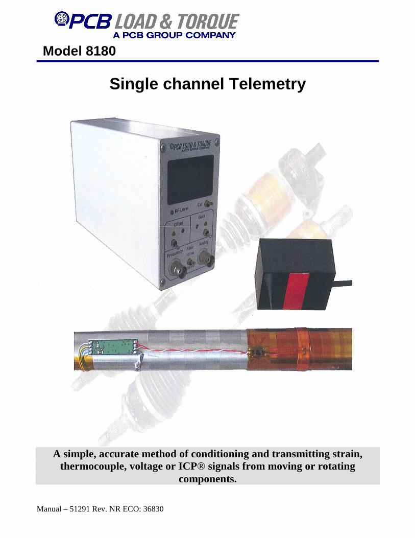
Model 8180
Manual – 51291 Rev. NR ECO: 36830
Single channel Telemetry
A simple, accurate method of conditioning and transmitting strain,
thermocouple, voltage or ICP® signals from moving or rotating components.
Model 8180
Manual – 51291 Rev. NR ECO: 36830
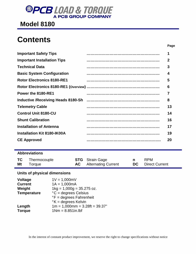
Contents Page Important Safety Tips ………………………………………………… 1
Important Installation Tips ………………………………………………… 2
Technical Data ………………………………………………… 3
Basic System Configuration ………………………………………………… 4
Rotor Electronics 8180-RE1 ………………………………………………… 5
Rotor Electronics 8180-RE1 ( Overview ) ………………………………………………… 6
Power the 8180-RE1 ………………………………………………… 7
Inductive /Receiving Heads 8180-Sh ………………………………………… ……… 8
Telemetry Cable ………………………………………………… 13
Control Unit 8180-CU ………………………………………………… 14
Shunt Calibration ………………………………………………… 16
Installation of Antenna ………………………………………………… 17
Installation Kit 8180-IK00A ………………………………………………… 19
CE Approved …………………………………………………. 20
Abbreviations
TC Thermocouple STG Strain Gage n RPM Mt Torque AC Alternating Current DC Direct Current Units of physical dimensions
Voltage 1V = 1,000mV Current 1A = 1,000mA Weight 1kg = 1,000g = 35.275 oz. Temperature ° C = degrees Celsius ° F = degrees Fahrenheit ° K = degrees Kelvin Length 1m = 1,000mm = 3.28ft = 39.37” Torque 1Nm = 8.851in.lbf
In the interest of constant product improvement, we reserve the right to change specifications without notice
Model 8180
Manual – 51291 Rev. NR ECO: 36830
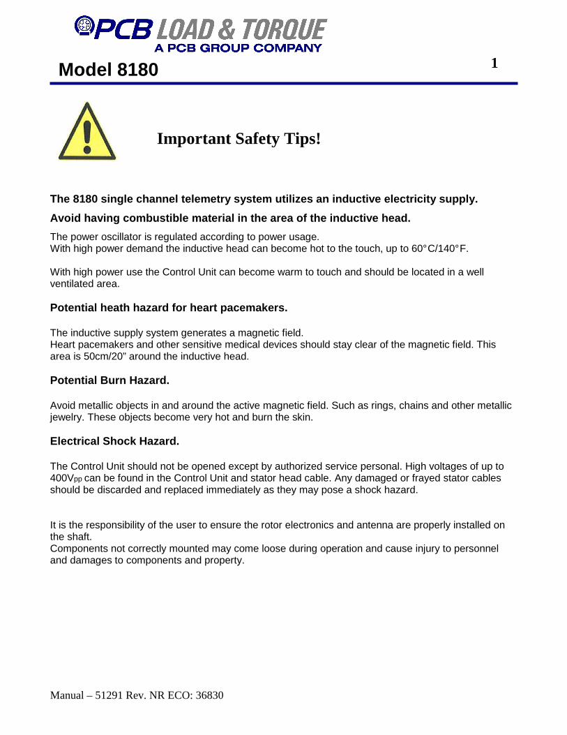
The 8180 single channel telemetry system utilizes a n inductive electricity supply.
Avoid having combustible material in the area of th e inductive head.
The power oscillator is regulated according to power usage. With high power demand the inductive head can become hot to the touch, up to 60° C/140° F. With high power use the Control Unit can become warm to touch and should be located in a well ventilated area. Potential heath hazard for heart pacemakers. The inductive supply system generates a magnetic field. Heart pacemakers and other sensitive medical devices should stay clear of the magnetic field. This area is 50cm/20” around the inductive head. Potential Burn Hazard. Avoid metallic objects in and around the active magnetic field. Such as rings, chains and other metallic jewelry. These objects become very hot and burn the skin. Electrical Shock Hazard. The Control Unit should not be opened except by authorized service personal. High voltages of up to 400Vpp can be found in the Control Unit and stator head cable. Any damaged or frayed stator cables should be discarded and replaced immediately as they may pose a shock hazard. It is the responsibility of the user to ensure the rotor electronics and antenna are properly installed on the shaft. Components not correctly mounted may come loose during operation and cause injury to personnel and damages to components and property.
Important Safety Tips!
1

Model 8180
Manual – 51291 Rev. NR ECO: 36830
Important Installation Tips! 8180 Installation All cable connections should be done with the power off. Only apply power to the Control unit with a stator head connected, otherwise damage to the Control Unit may occur. If the inductive head is placed on a metallic surface with the power on, the power oscillator will produce maximum power. While there is circuitry to prevent the system from being damaged for a short period of time, this must be avoided. The inductive head should be fastened to a non-metallic plate or bracket. If a metallic bracket is used the stator should be isolated from the metal by more than 5 mm of a non metallic material such as rubber or plastic. Mounting the stator near or on metal could produce unnecessary warming of the stator head and cause damage to the system. Every attempt should be made to keep a metal free area around the stator head for best operation. The installation of the 8180 single channel telemetry system requires the rotor electronics and antenna be mounted in such a way they do not come loose during operation. It is the responsibility of the user to ensure the components of the 8180 single channel telemetry system are properly installed. Knowledge of basic soldering techniques is required. Soldering should be preformed using a regulated soldering iron. The recommended temperature setting is 400 ° C / 752 ° F.
2
In the interest of constant product improvement, we reserve the right to change specifications without notice
Model 8180
Manual – 51291 Rev. NR ECO: 36830
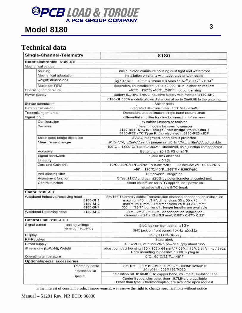
Technical data
3
In the interest of constant product improvement, we reserve the right to change specifications without notice
Model 8180
Manual – 51291 Rev. NR ECO: 36830
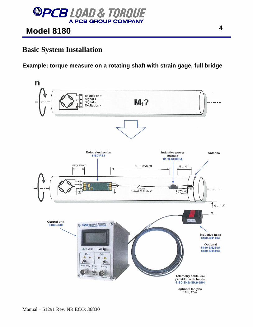
Basic System Installation Example: torque measure on a rotating shaft with st rain gage, full bridge
4
Model 8180
Manual – 51291 Rev. NR ECO: 36830
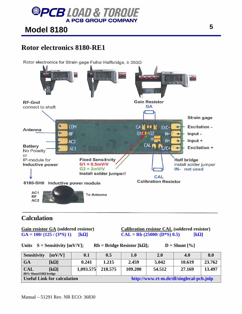
Rotor electronics 8180-RE1
Calculation Gain resistor GA (soldered resistor) Calibration resistor CAL (soldered resistor) GA = 100/ (125 / (3*S) 1) [kΩ] CAL = Rb (25000/ (D*S) 0.5) [kΩ] Units S = Sensitivity [mV/V]; Rb = Bridge Resistor [kΩ]; D = Shunt [%]
Sensitivity [mV/V] 0.1 0.5 1.0 2.0 4.0 8.0
GA [kΩ] 0.241 1.215 2.459 5.042 10.619 23.762
CAL [k Ω] 80% Shunt350Ω bridge
1,093.575 218.575 109.200 54.512 27.169 13.497
Useful Link for calculation http://www.rt-m.de/dl/singlecal-pcb.jnlp
5
Model 8180
Manual – 51291 Rev. NR ECO: 36830
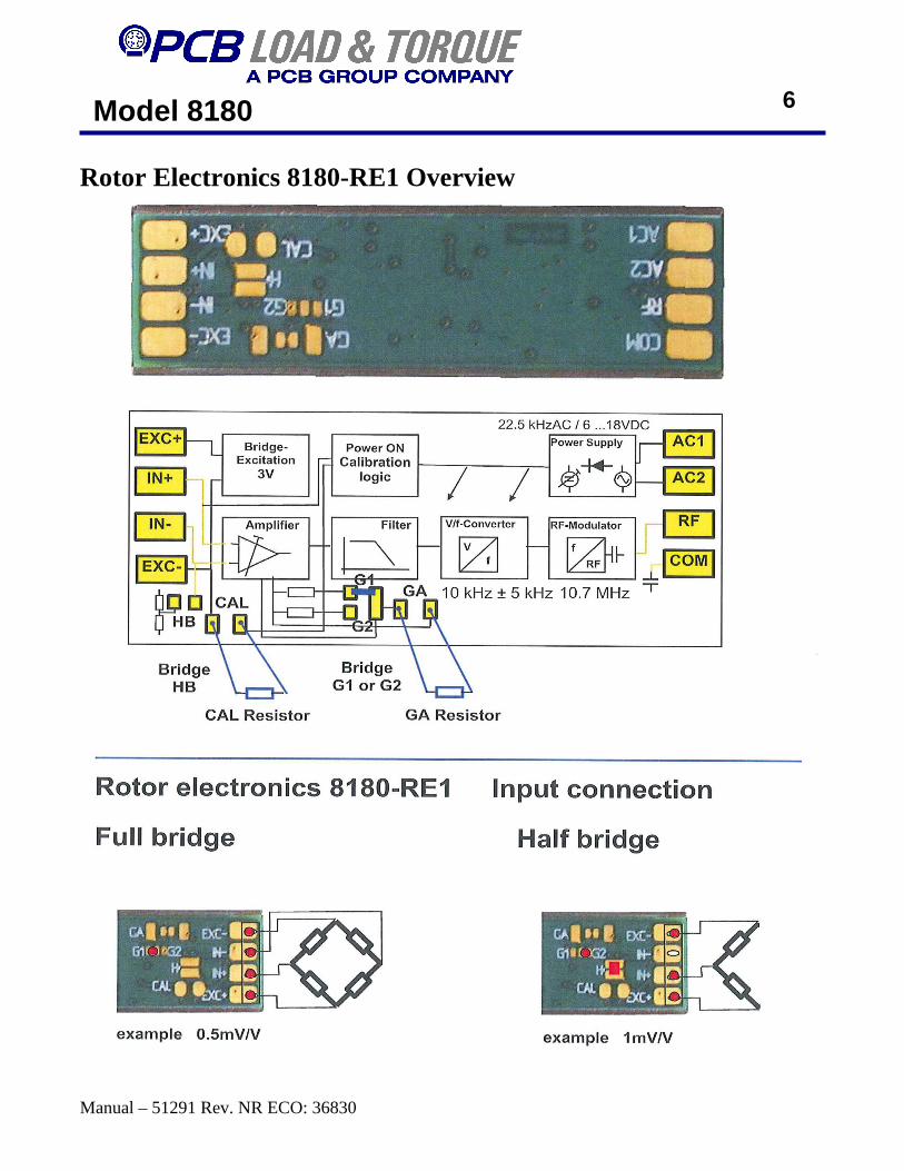
Rotor Electronics 8180-RE1 Overview
6
Model 8180
Manual – 51291 Rev. NR ECO: 36830
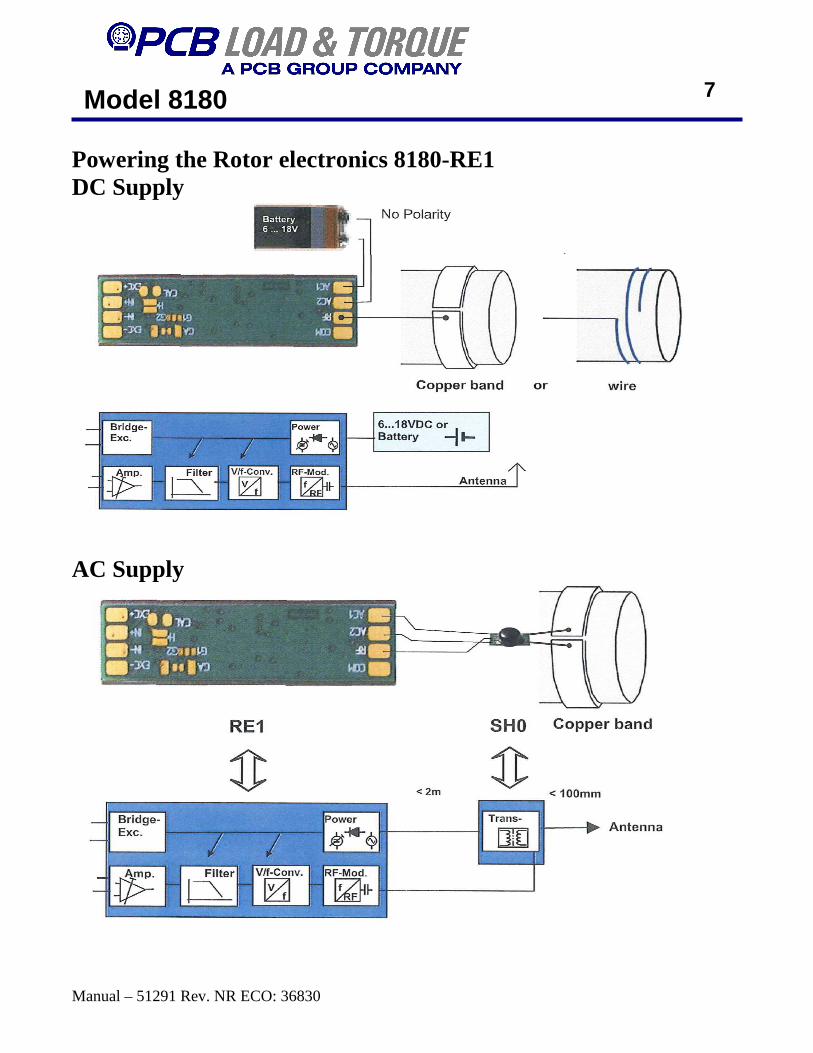
Powering the Rotor electronics 8180-RE1 DC Supply
AC Supply
7
Model 8180
Manual – 51291 Rev. NR ECO: 36830
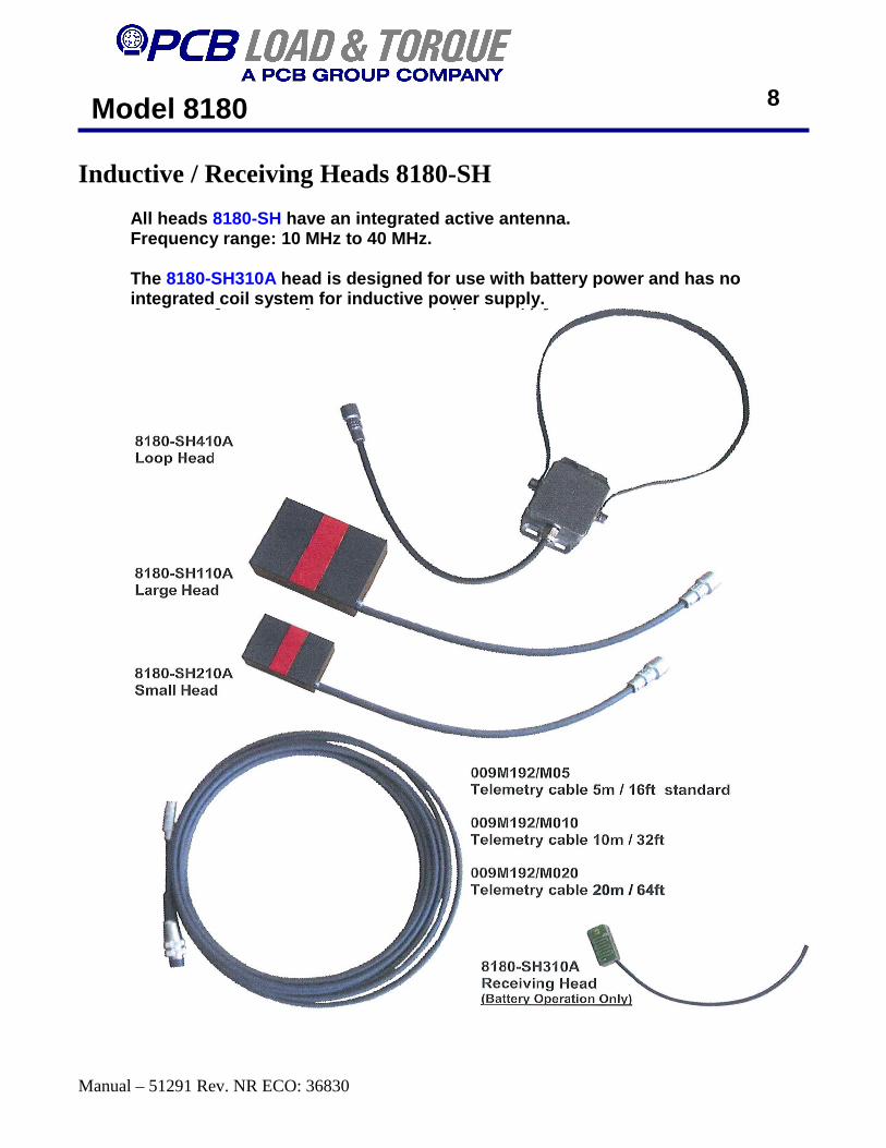
Inductive / Receiving Heads 8180-SH All heads 8180-SH have an integrated active antenna. Frequency range: 10 MHz to 40 MHz.
The 8180-SH310A head is designed for use with battery power and ha s no integrated coil system for inductive power supply.
8
Model 8180
Manual – 51291 Rev. NR ECO: 36830
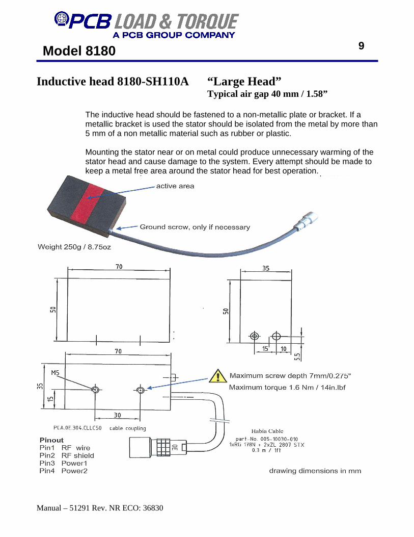
Inductive head 8180-SH110A “Large Head” Typical air gap 40 mm / 1.58”
The inductive head should be fastened to a non-metallic plate or bracket. If a metallic bracket is used the stator should be isolated from the metal by more than 5 mm of a non metallic material such as rubber or plastic. Mounting the stator near or on metal could produce unnecessary warming of the stator head and cause damage to the system. Every attempt should be made to keep a metal free area around the stator head for best operation.
9
Model 8180
Manual – 51291 Rev. NR ECO: 36830
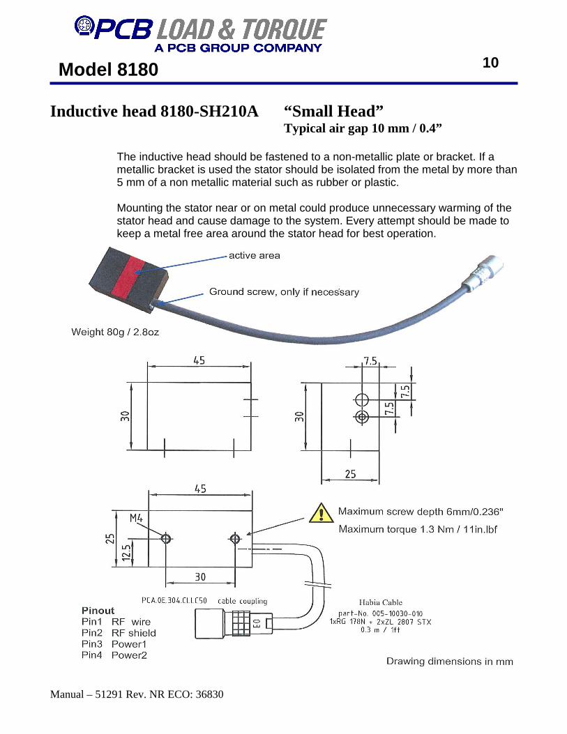
Inductive head 8180-SH210A “Small Head” Typical air gap 10 mm / 0.4”
The inductive head should be fastened to a non-metallic plate or bracket. If a metallic bracket is used the stator should be isolated from the metal by more than 5 mm of a non metallic material such as rubber or plastic. Mounting the stator near or on metal could produce unnecessary warming of the stator head and cause damage to the system. Every attempt should be made to keep a metal free area around the stator head for best operation.
10
Model 8180
Manual – 51291 Rev. NR ECO: 36830
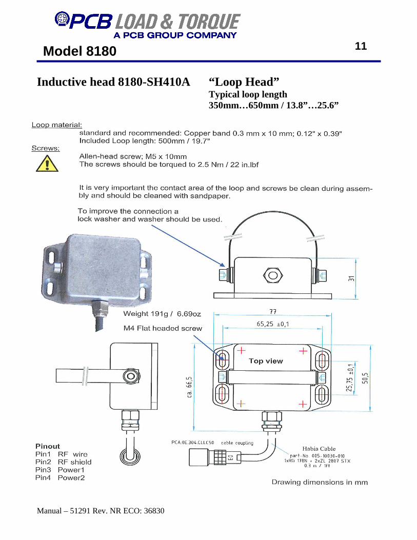
Inductive head 8180-SH410A “Loop Head” Typical loop length
350mm…650mm / 13.8”…25.6”
11

Model 8180
Manual – 51291 Rev. NR ECO: 36830
Receiving head 8180-SH310A “Antenna Head” Typical receiving distance
500mm/ 1.6ft The receiving head is designed for use with battery powered installations. It is not possible to inductively power the rotor electronics with the 8180-SH310A Head. While plug in the original connecting cable into the Control Unit the power oscillator is not switched on
12

Model 8180
Manual – 51291 Rev. NR ECO: 36830
Telemetry cable The Telemetry cable is supplied of the heads: 8180-SH110A 8180-SH210A 8180-SH410A with standard length 5m / 16ft.
As an optional accessory the telemetry cable is available in 3 lengths:
Length 5m / 16ft part 009M192/M05
Length 10m / 32ft part 009M192/M010
Length 20m / 64ft part 009M192/M020
13
The cable is resistant to most oils, lubricants, water and acids. The bending radius of the cable should not be less than 1”. Operating temperature range: -40° F to 248° F/ -40° C to 120° C
This cable is specially designed and manufactured for this system. It is extremely robust mechanically, and can be used in extreme environments. This cable should only be substituted with a direct replacement as a non approved cable will affect the data and tuning of the overall system.
Caution! Voltage up to 400Vpp, 22.5 kHz is on the cable. Only use the approved original cable. Damaged or frayed cable must be discarded and replaced immediately.
Model 8180
Manual – 51291 Rev. NR ECO: 36830
Control Unit 8180-CU0
14
Model 8180
Manual – 51291 Rev. NR ECO: 36830
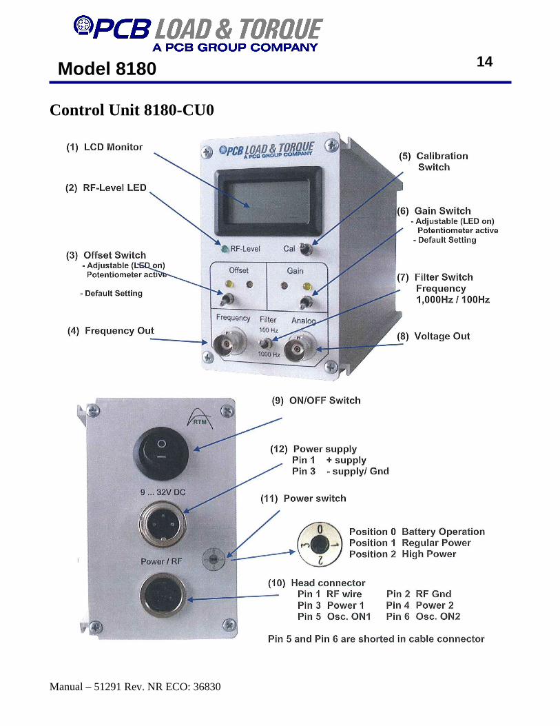
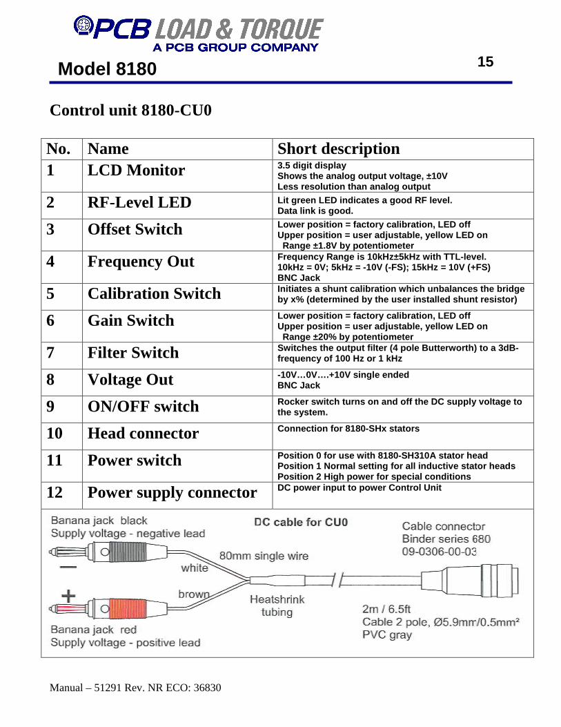
Control unit 8180-CU0 No. Name Short description 1 LCD Monitor 3.5 digit display
Shows the analog output voltage, ±10V Less resolution than analog output
2 RF-Level LED Lit green LED indicates a good RF level. Data link is good.
3 Offset Switch Lower position = factory calibration, LED off Upper position = user adjustable, yellow LED on Range ±1.8V by potentiometer
4 Frequency Out Frequency Range is 10kHz±5kHz with TTL-level. 10kHz = 0V; 5kHz = -10V (-FS); 15kHz = 10V (+FS) BNC Jack
5 Calibration Switch Initiates a shunt calibration which unbalances the bridge by x% (determined by the user installed shunt resis tor)
6 Gain Switch Lower position = factory calibration, LED off Upper position = user adjustable, yellow LED on Range ±20% by potentiometer
7 Filter Switch Switches the output filter (4 pole Butterworth) to a 3dB-frequency of 100 Hz or 1 kHz
8 Voltage Out -10V…0V….+10V single ended BNC Jack
9 ON/OFF switch Rocker switch turns on and off the DC supply voltag e to the system.
10 Head connector Connection for 8180-SHx stators
11 Power switch Position 0 for use with 8180-SH310A stator head Position 1 Normal setting for all inductive stator heads Position 2 High power for special conditions
12 Power supply connector DC power input to power Control Unit
15

Model 8180
Manual – 51291 Rev. NR ECO: 36830
Shunt Calibration The Shunt–Calibration is an accepted method to system functionality.
A resistor is placed in parallel to leg R in the picture below to unbalance the bridge to predefined value. This predefined value is determined by the value of resistor CAL. To calculate the resistor CAL value please see chapter “Rotor Electronics 8180-RE1.”
A shunt calibration is automatically initiated when power is supplied to the system. The shunt is invoked for approximately 2-3 seconds and can be viewed on the Control Unit display and can be measured at the analog and frequency output BNC connectors. The shunt cal function can be triggered manually by briefly pushing down on the cal switch located on the front panel of the Control Unit. The display and output will show a random value for approximately 8-10 seconds then for another 2-3 seconds the shunt value will be opened and displayed. After which the system returns to normal operation.
16
A high quality resistor should be used for the Shunt resistor and can be of form factors and construction: SMD 1206; 0805; 0603 or wired components.
Model 8180
Manual – 51291 Rev. NR ECO: 36830
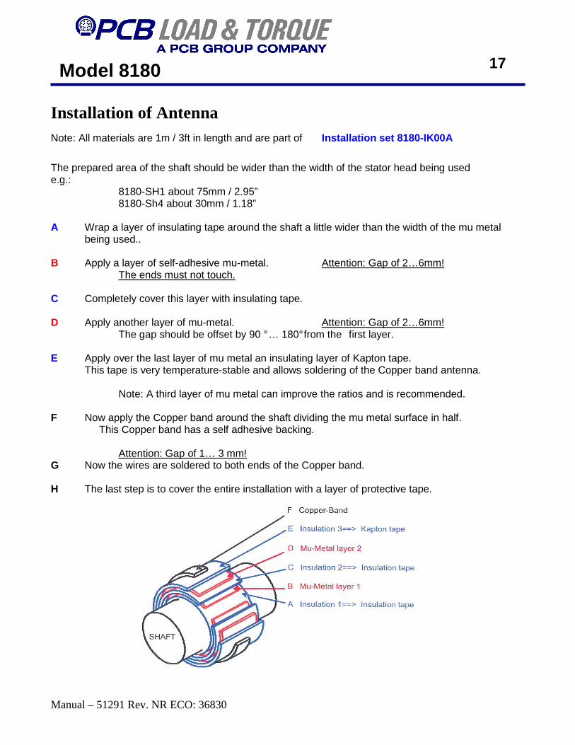
Installation of Antenna Note: All materials are 1m / 3ft in length and are part of Installation set 8180-IK00A
The prepared area of the shaft should be wider than the width of the stator head being used e.g.: 8180-SH1 about 75mm / 2.95” 8180-Sh4 about 30mm / 1.18” A Wrap a layer of insulating tape around the shaft a little wider than the width of the mu metal
being used.. B Apply a layer of self-adhesive mu-metal. Attention: Gap of 2…6mm! The ends must not touch. C Completely cover this layer with insulating tape. D Apply another layer of mu-metal. Attention: Gap of 2…6mm! The gap should be offset by 90 ° … 180° from the first layer. E Apply over the last layer of mu metal an insulating layer of Kapton tape. This tape is very temperature-stable and allows soldering of the Copper band antenna. Note: A third layer of mu metal can improve the ratios and is recommended. F Now apply the Copper band around the shaft dividing the mu metal surface in half. This Copper band has a self adhesive backing. Attention: Gap of 1… 3 mm! G Now the wires are soldered to both ends of the Copper band. H The last step is to cover the entire installation with a layer of protective tape.
17

Model 8180
Manual – 51291 Rev. NR ECO: 36830
18
Model 8180
Manual – 51291 Rev. NR ECO: 36830
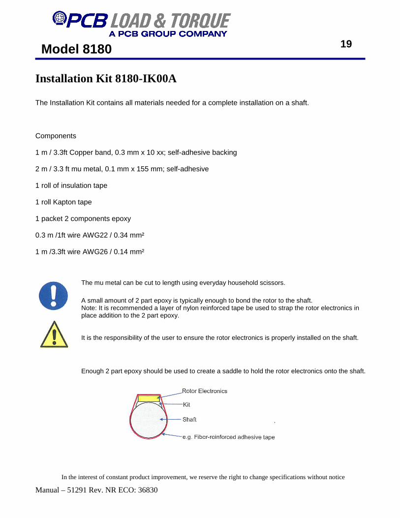
Installation Kit 8180-IK00A The Installation Kit contains all materials needed for a complete installation on a shaft. Components 1 m / 3.3ft Copper band, 0.3 mm x 10 xx; self-adhesive backing 2 m / 3.3 ft mu metal, 0.1 mm x 155 mm; self-adhesive 1 roll of insulation tape 1 roll Kapton tape 1 packet 2 components epoxy 0.3 m /1ft wire AWG22 / 0.34 mm² 1 m /3.3ft wire AWG26 / 0.14 mm²
19
The mu metal can be cut to length using everyday household scissors.
It is the responsibility of the user to ensure the rotor electronics is properly installed on the shaft.
A small amount of 2 part epoxy is typically enough to bond the rotor to the shaft. Note: It is recommended a layer of nylon reinforced tape be used to strap the rotor electronics in place addition to the 2 part epoxy.
Enough 2 part epoxy should be used to create a saddle to hold the rotor electronics onto the shaft.
In the interest of constant product improvement, we reserve the right to change specifications without notice

Model 8180
Manual – 51291 Rev. NR ECO: 36830
Rainer Thomas Messtechnik GmbH Ludwig-Erhard-Platz 2 D-83703 Gmund am Tegernsee Germany
EC – Certificate of Conformity
We hereby certify, that the model of the subsequently designated device corresponds to the es- sential relevant EC-guidelines mentioned below during compatibility evaluation of the product. Any changes not agreed with us, will void this declaration.
Description: 1-channel-Telemetry Type: 8179; 8180 Serial numbers: 0290 to 0999
Relevant EC-guidelines: Radio and Spectrum engineering parameters: EN 300 220-3 Electromagnetic Compatibility: EN 301 489-01 and 301 489-03 Electric safety: EN 60 950
The device was tested in a typical situation.