MODEL 430 POWER SUPPLY PROGRAMMER
254
American Magnetics, Inc. P.O. Box 2509, 112 Flint Road, Oak Ridge, TN 37831-2509, Tel: 865-482-1056, Fax: 865-482-5472 Rev. 9, July 2017 MODEL 430 POWER SUPPLY PROGRAMMER INCLUDING HIGH-STABILITY OPTION & MULTI-AXIS APPLICATIONS INSTALLATION, OPERATION, AND MAINTENANCE INSTRUCTIONS EXCELLENCE IN MAGNETICS AND CRYOGENICS
Transcript of MODEL 430 POWER SUPPLY PROGRAMMER

American Magnetics, Inc.P.O. Box 2509, 112 Flint Road, Oak Ridge, TN 37831-2509, Tel: 865-482-1056, Fax: 865-482-5472
Rev. 9, July 2017
MODEL 430 POWER SUPPLY PROGRAMMER
INCLUDING HIGH-STABILITY OPTION & MULTI-AXIS APPLICATIONS
INSTALLATION, OPERATION, AND MAINTENANCE INSTRUCTIONS
EXCELLENCE IN MAGNETICS AND CRYOGENICS


AMERICAN MAGNETICS, INC. TABLE OF CONTENTS
Foreword .................................................................................. ixPurpose and Scope . . . . . . . . . . . . . . . . . . . . . . . . . . . . . . . . . . . . . . . . . . . . . . . . . . . . . . ix
Contents of this Manual . . . . . . . . . . . . . . . . . . . . . . . . . . . . . . . . . . . . . . . . . . . . . . . . . . ix
Applicable Hardware . . . . . . . . . . . . . . . . . . . . . . . . . . . . . . . . . . . . . . . . . . . . . . . . . . . . . .x
General Precautions . . . . . . . . . . . . . . . . . . . . . . . . . . . . . . . . . . . . . . . . . . . . . . . . . . . . . xiCryogen Safety. . . . . . . . . . . . . . . . . . . . . . . . . . . . . . . . . . . . . . . . . . . . . . . . . . . . . . . . . . . . . . . . . . . xiTreating Cold Burns . . . . . . . . . . . . . . . . . . . . . . . . . . . . . . . . . . . . . . . . . . . . . . . . . . . . . . . . . . . . . . . xiiHandling Cryogenic Liquids . . . . . . . . . . . . . . . . . . . . . . . . . . . . . . . . . . . . . . . . . . . . . . . . . . . . . . . . . xiiMaterial Safety at Cryogenic Temperatures . . . . . . . . . . . . . . . . . . . . . . . . . . . . . . . . . . . . . . . . . . . . . xiiMagnet Quenches in LHe-Cooled Systems . . . . . . . . . . . . . . . . . . . . . . . . . . . . . . . . . . . . . . . . . . . . xiiiRisk of Explosion . . . . . . . . . . . . . . . . . . . . . . . . . . . . . . . . . . . . . . . . . . . . . . . . . . . . . . . . . . . . . . . . xiiiMagnetic Fields . . . . . . . . . . . . . . . . . . . . . . . . . . . . . . . . . . . . . . . . . . . . . . . . . . . . . . . . . . . . . . . . . xiii
Safety Summary. . . . . . . . . . . . . . . . . . . . . . . . . . . . . . . . . . . . . . . . . . . . . . . . . . . . . . . . xivMinimum Recommended Safety Equipment . . . . . . . . . . . . . . . . . . . . . . . . . . . . . . . . . . . . . . . . . . . xivSafety Legend . . . . . . . . . . . . . . . . . . . . . . . . . . . . . . . . . . . . . . . . . . . . . . . . . . . . . . . . . . . . . . . . . . .xv
Introduction ...............................................................................1Model 430 Programmer Features . . . . . . . . . . . . . . . . . . . . . . . . . . . . . . . . . . . . . . . . . . . .1
Digitally-Controlled . . . . . . . . . . . . . . . . . . . . . . . . . . . . . . . . . . . . . . . . . . . . . . . . . . . . . . . . . . . . . . . . 1Superior Resolution and Stability . . . . . . . . . . . . . . . . . . . . . . . . . . . . . . . . . . . . . . . . . . . . . . . . . . . . . 1High-Stability Option. . . . . . . . . . . . . . . . . . . . . . . . . . . . . . . . . . . . . . . . . . . . . . . . . . . . . . . . . . . . . . . 2Intuitive Human-Interface Design . . . . . . . . . . . . . . . . . . . . . . . . . . . . . . . . . . . . . . . . . . . . . . . . . . . . . 2Flexibility . . . . . . . . . . . . . . . . . . . . . . . . . . . . . . . . . . . . . . . . . . . . . . . . . . . . . . . . . . . . . . . . . . . . . . . . 2Standard Remote Interfaces. . . . . . . . . . . . . . . . . . . . . . . . . . . . . . . . . . . . . . . . . . . . . . . . . . . . . . . . . 2Programmable Safety Features . . . . . . . . . . . . . . . . . . . . . . . . . . . . . . . . . . . . . . . . . . . . . . . . . . . . . . 2Condition-Based Magnet Auto-Rampdown . . . . . . . . . . . . . . . . . . . . . . . . . . . . . . . . . . . . . . . . . . . . . 3
Model 430 Front Panel Layout . . . . . . . . . . . . . . . . . . . . . . . . . . . . . . . . . . . . . . . . . . . . . .4
Model 430 Rear Panel Layout . . . . . . . . . . . . . . . . . . . . . . . . . . . . . . . . . . . . . . . . . . . . . .5
Model 430 Specifications @ 25 °C . . . . . . . . . . . . . . . . . . . . . . . . . . . . . . . . . . . . . . . . . . .7
Operating Characteristics . . . . . . . . . . . . . . . . . . . . . . . . . . . . . . . . . . . . . . . . . . . . . . . . . .9Single-Quadrant Operation. . . . . . . . . . . . . . . . . . . . . . . . . . . . . . . . . . . . . . . . . . . . . . . . . . . . . . . . . . 9Dual-Quadrant Operation . . . . . . . . . . . . . . . . . . . . . . . . . . . . . . . . . . . . . . . . . . . . . . . . . . . . . . . . . . 10Four-Quadrant Operation . . . . . . . . . . . . . . . . . . . . . . . . . . . . . . . . . . . . . . . . . . . . . . . . . . . . . . . . . . 11
REV 9 III

AMERICAN MAGNETICS, INC. TABLE OF CONTENTS
Installation............................................................................... 13Inspecting and Unpacking . . . . . . . . . . . . . . . . . . . . . . . . . . . . . . . . . . . . . . . . . . . . . . . . 14
Model 430 Programmer. . . . . . . . . . . . . . . . . . . . . . . . . . . . . . . . . . . . . . . . . . . . . . . . . . . 14
Power Requirements. . . . . . . . . . . . . . . . . . . . . . . . . . . . . . . . . . . . . . . . . . . . . . . . . . . . . 14Changing the Model 430 Programmer Operating Voltage . . . . . . . . . . . . . . . . . . . . . . . . . . . . . . . . . 15
Collecting Necessary Information . . . . . . . . . . . . . . . . . . . . . . . . . . . . . . . . . . . . . . . . . . 16
System Interconnects (Single-Axis Systems) . . . . . . . . . . . . . . . . . . . . . . . . . . . . . . . . 16Unipolar Power Supply System. . . . . . . . . . . . . . . . . . . . . . . . . . . . . . . . . . . . . . . . . . . . . . . . . . . . . . 18Bipolar Power Supply System. . . . . . . . . . . . . . . . . . . . . . . . . . . . . . . . . . . . . . . . . . . . . . . . . . . . . . . 21High-Stability Bipolar Power Supply System. . . . . . . . . . . . . . . . . . . . . . . . . . . . . . . . . . . . . . . . . . . . 24High-Current Four-Quadrant Power Supply System. . . . . . . . . . . . . . . . . . . . . . . . . . . . . . . . . . . . . . 28High-Current, High-Stability 4-Quadrant Power Supply System. . . . . . . . . . . . . . . . . . . . . . . . . . . . . 31Low-Current, High-Resolution 4-Quadrant Power Supply System . . . . . . . . . . . . . . . . . . . . . . . . . . . 34
System Interconnects (Multi-Axis Systems). . . . . . . . . . . . . . . . . . . . . . . . . . . . . . . . . . 37General . . . . . . . . . . . . . . . . . . . . . . . . . . . . . . . . . . . . . . . . . . . . . . . . . . . . . . . . . . . . . . . . . . . . . . . . 37Load Cables . . . . . . . . . . . . . . . . . . . . . . . . . . . . . . . . . . . . . . . . . . . . . . . . . . . . . . . . . . . . . . . . . . . . 37Instrumentation Cables . . . . . . . . . . . . . . . . . . . . . . . . . . . . . . . . . . . . . . . . . . . . . . . . . . . . . . . . . . . . 37Standard (non-recondensing) Helium-based 2-Axis System Signal Interconnects . . . . . . . . . . . . . . 38Standard (non-recondensing) Helium-based 3-Axis System Signal Interconnects . . . . . . . . . . . . . . 39Recondensing Helium-based 2-Axis System Signal Interconnects . . . . . . . . . . . . . . . . . . . . . . . . . . 40Recondensing Helium-based 3-Axis System Signal Interconnects . . . . . . . . . . . . . . . . . . . . . . . . . . 41Cryogen-Free 2-Axis System Signal Interconnects . . . . . . . . . . . . . . . . . . . . . . . . . . . . . . . . . . . . . . 42Cryogen-Free 3-Axis System Signal Interconnects . . . . . . . . . . . . . . . . . . . . . . . . . . . . . . . . . . . . . . 42
Third-Party Power Supplies . . . . . . . . . . . . . . . . . . . . . . . . . . . . . . . . . . . . . . . . . . . . . . . 43
Special Configurations . . . . . . . . . . . . . . . . . . . . . . . . . . . . . . . . . . . . . . . . . . . . . . . . . . . 43Superconducting Magnets with No Persistent Switch. . . . . . . . . . . . . . . . . . . . . . . . . . . . . . . . . . . . . 43Short-Circuit or Resistive Load . . . . . . . . . . . . . . . . . . . . . . . . . . . . . . . . . . . . . . . . . . . . . . . . . . . . . . 44
Power-Up and Test Procedure . . . . . . . . . . . . . . . . . . . . . . . . . . . . . . . . . . . . . . . . . . . . . 45
Operation ................................................................................ 49System Power On/Off Sequence . . . . . . . . . . . . . . . . . . . . . . . . . . . . . . . . . . . . . . . . . . . 49
Model 430 Programmer Power On/Off . . . . . . . . . . . . . . . . . . . . . . . . . . . . . . . . . . . . . . . . . . . . . . . . 49Energizing the Power Supply and Components . . . . . . . . . . . . . . . . . . . . . . . . . . . . . . . . . . . . . . . . . 50
Model 430 Programmer Default Display . . . . . . . . . . . . . . . . . . . . . . . . . . . . . . . . . . . . . 51
iv REV 9

AMERICAN MAGNETICS, INC. TABLE OF CONTENTS
Field / Current Display . . . . . . . . . . . . . . . . . . . . . . . . . . . . . . . . . . . . . . . . . . . . . . . . . . . . . . . . . . . . 51Voltage Display. . . . . . . . . . . . . . . . . . . . . . . . . . . . . . . . . . . . . . . . . . . . . . . . . . . . . . . . . . . . . . . . . . 52Status Indicator. . . . . . . . . . . . . . . . . . . . . . . . . . . . . . . . . . . . . . . . . . . . . . . . . . . . . . . . . . . . . . . . . . 53Main Display . . . . . . . . . . . . . . . . . . . . . . . . . . . . . . . . . . . . . . . . . . . . . . . . . . . . . . . . . . . . . . . . . . . . 53
Entering Numeric Values. . . . . . . . . . . . . . . . . . . . . . . . . . . . . . . . . . . . . . . . . . . . . . . . . .54
Using the Fine Adjust Knob . . . . . . . . . . . . . . . . . . . . . . . . . . . . . . . . . . . . . . . . . . . . . . .55
Selecting Picklist Values. . . . . . . . . . . . . . . . . . . . . . . . . . . . . . . . . . . . . . . . . . . . . . . . . .57
Single-key Commands / Menus . . . . . . . . . . . . . . . . . . . . . . . . . . . . . . . . . . . . . . . . . . . .58Persistent Switch Control Key . . . . . . . . . . . . . . . . . . . . . . . . . . . . . . . . . . . . . . . . . . . . . . . . . . . . . . 58Target Field Setpoint Key . . . . . . . . . . . . . . . . . . . . . . . . . . . . . . . . . . . . . . . . . . . . . . . . . . . . . . . . . 61Ramp / Pause Key . . . . . . . . . . . . . . . . . . . . . . . . . . . . . . . . . . . . . . . . . . . . . . . . . . . . . . . . . . . . . . . 61Ramp To Zero Key . . . . . . . . . . . . . . . . . . . . . . . . . . . . . . . . . . . . . . . . . . . . . . . . . . . . . . . . . . . . . . . 62
SHIFT+key Commands / Menus . . . . . . . . . . . . . . . . . . . . . . . . . . . . . . . . . . . . . . . . . . . .62Ramp Rate (Shift+1). . . . . . . . . . . . . . . . . . . . . . . . . . . . . . . . . . . . . . . . . . . . . . . . . . . . . . . . . . . . . . 63Voltage Limit (Shift+2) . . . . . . . . . . . . . . . . . . . . . . . . . . . . . . . . . . . . . . . . . . . . . . . . . . . . . . . . . . . . 66Reset Quench (Shift+3) . . . . . . . . . . . . . . . . . . . . . . . . . . . . . . . . . . . . . . . . . . . . . . . . . . . . . . . . . . . 67Increment Field (Shift+4) . . . . . . . . . . . . . . . . . . . . . . . . . . . . . . . . . . . . . . . . . . . . . . . . . . . . . . . . . . 67Field <> Current (Shift+5) . . . . . . . . . . . . . . . . . . . . . . . . . . . . . . . . . . . . . . . . . . . . . . . . . . . . . . . . . . 67Decrement Field (Shift+6). . . . . . . . . . . . . . . . . . . . . . . . . . . . . . . . . . . . . . . . . . . . . . . . . . . . . . . . . . 68Field Units (Shift+7) . . . . . . . . . . . . . . . . . . . . . . . . . . . . . . . . . . . . . . . . . . . . . . . . . . . . . . . . . . . . . . 68Persistent Switch Heater Current (Shift+8). . . . . . . . . . . . . . . . . . . . . . . . . . . . . . . . . . . . . . . . . . . . . 68Stability (Shift+9) . . . . . . . . . . . . . . . . . . . . . . . . . . . . . . . . . . . . . . . . . . . . . . . . . . . . . . . . . . . . . . . . 69Vs <> Vm (Shift+0) . . . . . . . . . . . . . . . . . . . . . . . . . . . . . . . . . . . . . . . . . . . . . . . . . . . . . . . . . . . . . . . 69Volt Meter (Shift+.) . . . . . . . . . . . . . . . . . . . . . . . . . . . . . . . . . . . . . . . . . . . . . . . . . . . . . . . . . . . . . . . 69Fine Adjust (Shift +/-) . . . . . . . . . . . . . . . . . . . . . . . . . . . . . . . . . . . . . . . . . . . . . . . . . . . . . . . . . . . . . 69Shift + Persist. Switch Control . . . . . . . . . . . . . . . . . . . . . . . . . . . . . . . . . . . . . . . . . . . . . . . . . . . . . . 69
LED Indicators . . . . . . . . . . . . . . . . . . . . . . . . . . . . . . . . . . . . . . . . . . . . . . . . . . . . . . . . . .70Power-on Indicator . . . . . . . . . . . . . . . . . . . . . . . . . . . . . . . . . . . . . . . . . . . . . . . . . . . . . . . . . . . . . . . 70Magnet Status Indicators . . . . . . . . . . . . . . . . . . . . . . . . . . . . . . . . . . . . . . . . . . . . . . . . . . . . . . . . . . 70Shift Indicator . . . . . . . . . . . . . . . . . . . . . . . . . . . . . . . . . . . . . . . . . . . . . . . . . . . . . . . . . . . . . . . . . . . 71
Setup Menu. . . . . . . . . . . . . . . . . . . . . . . . . . . . . . . . . . . . . . . . . . . . . . . . . . . . . . . . . . . . .72Entering / Exiting Setup Menu . . . . . . . . . . . . . . . . . . . . . . . . . . . . . . . . . . . . . . . . . . . . . . . . . . . . . . 72Menu Navigation. . . . . . . . . . . . . . . . . . . . . . . . . . . . . . . . . . . . . . . . . . . . . . . . . . . . . . . . . . . . . . . . . 72
Setup Submenu Descriptions. . . . . . . . . . . . . . . . . . . . . . . . . . . . . . . . . . . . . . . . . . . . . .73Supply Submenu . . . . . . . . . . . . . . . . . . . . . . . . . . . . . . . . . . . . . . . . . . . . . . . . . . . . . . . . . . . . . . . . 73Load Submenu . . . . . . . . . . . . . . . . . . . . . . . . . . . . . . . . . . . . . . . . . . . . . . . . . . . . . . . . . . . . . . . . . . 78Switch Submenu. . . . . . . . . . . . . . . . . . . . . . . . . . . . . . . . . . . . . . . . . . . . . . . . . . . . . . . . . . . . . . . . . 83
REV 9 V

AMERICAN MAGNETICS, INC. TABLE OF CONTENTS
Protection Submenu . . . . . . . . . . . . . . . . . . . . . . . . . . . . . . . . . . . . . . . . . . . . . . . . . . . . . . . . . . . . . . 88Misc Submenu . . . . . . . . . . . . . . . . . . . . . . . . . . . . . . . . . . . . . . . . . . . . . . . . . . . . . . . . . . . . . . . . . . 95Net Settings Submenu . . . . . . . . . . . . . . . . . . . . . . . . . . . . . . . . . . . . . . . . . . . . . . . . . . . . . . . . . . . 104Net Setup Submenu . . . . . . . . . . . . . . . . . . . . . . . . . . . . . . . . . . . . . . . . . . . . . . . . . . . . . . . . . . . . . 106
Example Setup. . . . . . . . . . . . . . . . . . . . . . . . . . . . . . . . . . . . . . . . . . . . . . . . . . . . . . . . . 108
Ramping Functions . . . . . . . . . . . . . . . . . . . . . . . . . . . . . . . . . . . . . . . . . . . . . . . . . . . . 110Ramping States and Controls . . . . . . . . . . . . . . . . . . . . . . . . . . . . . . . . . . . . . . . . . . . . . . . . . . . . . 110Manual Ramping. . . . . . . . . . . . . . . . . . . . . . . . . . . . . . . . . . . . . . . . . . . . . . . . . . . . . . . . . . . . . . . . 111Automatic Ramping. . . . . . . . . . . . . . . . . . . . . . . . . . . . . . . . . . . . . . . . . . . . . . . . . . . . . . . . . . . . . . 111Ramping to Zero . . . . . . . . . . . . . . . . . . . . . . . . . . . . . . . . . . . . . . . . . . . . . . . . . . . . . . . . . . . . . . . . 112Fine Adjust of Field / Current in Holding Mode . . . . . . . . . . . . . . . . . . . . . . . . . . . . . . . . . . . . . . . . . 112
Persistent Switch Control. . . . . . . . . . . . . . . . . . . . . . . . . . . . . . . . . . . . . . . . . . . . . . . . 113Procedure for Initial Heating of the Switch . . . . . . . . . . . . . . . . . . . . . . . . . . . . . . . . . . . . . . . . . . . . 113Procedure for Entering Persistent Mode . . . . . . . . . . . . . . . . . . . . . . . . . . . . . . . . . . . . . . . . . . . . . 114Procedure for Exiting Persistent Mode . . . . . . . . . . . . . . . . . . . . . . . . . . . . . . . . . . . . . . . . . . . . . . . 117Toggling the State of the Persistent Switch Heater. . . . . . . . . . . . . . . . . . . . . . . . . . . . . . . . . . . . . . 120
Ramping Functions Example . . . . . . . . . . . . . . . . . . . . . . . . . . . . . . . . . . . . . . . . . . . . 121
Quench Detection . . . . . . . . . . . . . . . . . . . . . . . . . . . . . . . . . . . . . . . . . . . . . . . . . . . . . . 123Quench Detection Method . . . . . . . . . . . . . . . . . . . . . . . . . . . . . . . . . . . . . . . . . . . . . . . . . . . . . . . . 123External Quench Detection . . . . . . . . . . . . . . . . . . . . . . . . . . . . . . . . . . . . . . . . . . . . . . . . . . . . . . . . 124Disabling Internal Quench Detection. . . . . . . . . . . . . . . . . . . . . . . . . . . . . . . . . . . . . . . . . . . . . . . . . 124
External Rampdown . . . . . . . . . . . . . . . . . . . . . . . . . . . . . . . . . . . . . . . . . . . . . . . . . . . . 125External Rampdown while in Persistent Mode . . . . . . . . . . . . . . . . . . . . . . . . . . . . . . . . . . . . . . . . . 126External Rampdown while not in Persistent Mode . . . . . . . . . . . . . . . . . . . . . . . . . . . . . . . . . . . . . . 127
Summary of Limits and Default Settings . . . . . . . . . . . . . . . . . . . . . . . . . . . . . . . . . . . 128
Remote Interface Reference................................................... 129SCPI Command Summary . . . . . . . . . . . . . . . . . . . . . . . . . . . . . . . . . . . . . . . . . . . . . . . 129
Programming Overview . . . . . . . . . . . . . . . . . . . . . . . . . . . . . . . . . . . . . . . . . . . . . . . . . 137SCPI Language Introduction . . . . . . . . . . . . . . . . . . . . . . . . . . . . . . . . . . . . . . . . . . . . . . . . . . . . . . . 137SCPI Status System . . . . . . . . . . . . . . . . . . . . . . . . . . . . . . . . . . . . . . . . . . . . . . . . . . . . . . . . . . . . . 137Status Byte Register . . . . . . . . . . . . . . . . . . . . . . . . . . . . . . . . . . . . . . . . . . . . . . . . . . . . . . . . . . . . . 139Standard Event Register . . . . . . . . . . . . . . . . . . . . . . . . . . . . . . . . . . . . . . . . . . . . . . . . . . . . . . . . . . 140Command Handshaking . . . . . . . . . . . . . . . . . . . . . . . . . . . . . . . . . . . . . . . . . . . . . . . . . . . . . . . . . . 141
RS-232 Configuration . . . . . . . . . . . . . . . . . . . . . . . . . . . . . . . . . . . . . . . . . . . . . . . . . . . 143
vi REV 9

AMERICAN MAGNETICS, INC. TABLE OF CONTENTS
Serial Connector. . . . . . . . . . . . . . . . . . . . . . . . . . . . . . . . . . . . . . . . . . . . . . . . . . . . . . . . . . . . . . . . 143Termination Characters . . . . . . . . . . . . . . . . . . . . . . . . . . . . . . . . . . . . . . . . . . . . . . . . . . . . . . . . . . 143
Ethernet Configuration . . . . . . . . . . . . . . . . . . . . . . . . . . . . . . . . . . . . . . . . . . . . . . . . . .143Ethernet Connector . . . . . . . . . . . . . . . . . . . . . . . . . . . . . . . . . . . . . . . . . . . . . . . . . . . . . . . . . . . . . 144Termination Characters . . . . . . . . . . . . . . . . . . . . . . . . . . . . . . . . . . . . . . . . . . . . . . . . . . . . . . . . . . 144Port Assignments . . . . . . . . . . . . . . . . . . . . . . . . . . . . . . . . . . . . . . . . . . . . . . . . . . . . . . . . . . . . . . . 144Telnet Port 23 Broadcast Protocol . . . . . . . . . . . . . . . . . . . . . . . . . . . . . . . . . . . . . . . . . . . . . . . . . . 144
Command Reference. . . . . . . . . . . . . . . . . . . . . . . . . . . . . . . . . . . . . . . . . . . . . . . . . . . .148System-Related Commands. . . . . . . . . . . . . . . . . . . . . . . . . . . . . . . . . . . . . . . . . . . . . . . . . . . . . . . 148Status System Commands . . . . . . . . . . . . . . . . . . . . . . . . . . . . . . . . . . . . . . . . . . . . . . . . . . . . . . . . 150Supply Setup Configuration Queries . . . . . . . . . . . . . . . . . . . . . . . . . . . . . . . . . . . . . . . . . . . . . . . . 152Load Setup Configuration Commands and Queries. . . . . . . . . . . . . . . . . . . . . . . . . . . . . . . . . . . . . 154Switch Setup Configuration Commands and Queries . . . . . . . . . . . . . . . . . . . . . . . . . . . . . . . . . . . 156Protection Setup Configuration Commands and Queries. . . . . . . . . . . . . . . . . . . . . . . . . . . . . . . . . 157Misc Setup Configuration Commands and Queries . . . . . . . . . . . . . . . . . . . . . . . . . . . . . . . . . . . . . 160Lock Commands and Queries . . . . . . . . . . . . . . . . . . . . . . . . . . . . . . . . . . . . . . . . . . . . . . . . . . . . . 161Net Setup Configuration Commands and Queries . . . . . . . . . . . . . . . . . . . . . . . . . . . . . . . . . . . . . . 167Ramp Target/Rate Configuration Commands and Queries . . . . . . . . . . . . . . . . . . . . . . . . . . . . . . . 167Measurement Commands and Queries . . . . . . . . . . . . . . . . . . . . . . . . . . . . . . . . . . . . . . . . . . . . . . 169Ramping State Commands and Queries . . . . . . . . . . . . . . . . . . . . . . . . . . . . . . . . . . . . . . . . . . . . . 170Switch Heater Command and Query . . . . . . . . . . . . . . . . . . . . . . . . . . . . . . . . . . . . . . . . . . . . . . . . 171Quench State Commands and Queries . . . . . . . . . . . . . . . . . . . . . . . . . . . . . . . . . . . . . . . . . . . . . . 172Rampdown State Commands and Queries . . . . . . . . . . . . . . . . . . . . . . . . . . . . . . . . . . . . . . . . . . . 173Trigger Functions . . . . . . . . . . . . . . . . . . . . . . . . . . . . . . . . . . . . . . . . . . . . . . . . . . . . . . . . . . . . . . . 176
Error Messages . . . . . . . . . . . . . . . . . . . . . . . . . . . . . . . . . . . . . . . . . . . . . . . . . . . . . . . .178Command Errors . . . . . . . . . . . . . . . . . . . . . . . . . . . . . . . . . . . . . . . . . . . . . . . . . . . . . . . . . . . . . . . 178Query Errors . . . . . . . . . . . . . . . . . . . . . . . . . . . . . . . . . . . . . . . . . . . . . . . . . . . . . . . . . . . . . . . . . . . 180Execution Errors . . . . . . . . . . . . . . . . . . . . . . . . . . . . . . . . . . . . . . . . . . . . . . . . . . . . . . . . . . . . . . . . 180Device Errors . . . . . . . . . . . . . . . . . . . . . . . . . . . . . . . . . . . . . . . . . . . . . . . . . . . . . . . . . . . . . . . . . . 181
Service ................................................................................... 183System Component Routine Maintenance . . . . . . . . . . . . . . . . . . . . . . . . . . . . . . . . . .183
Troubleshooting Hints. . . . . . . . . . . . . . . . . . . . . . . . . . . . . . . . . . . . . . . . . . . . . . . . . . .183Electrostatic Discharge Precautions. . . . . . . . . . . . . . . . . . . . . . . . . . . . . . . . . . . . . . . . . . . . . . . . . 183Hints for Commonly Encountered Errors . . . . . . . . . . . . . . . . . . . . . . . . . . . . . . . . . . . . . . . . . . . . . 184
Additional Technical Support . . . . . . . . . . . . . . . . . . . . . . . . . . . . . . . . . . . . . . . . . . . . .191
Return Authorization . . . . . . . . . . . . . . . . . . . . . . . . . . . . . . . . . . . . . . . . . . . . . . . . . . . .191
REV 9 VII

AMERICAN MAGNETICS, INC. TABLE OF CONTENTS
Appendix ............................................................................... 193Magnet Station Connectors . . . . . . . . . . . . . . . . . . . . . . . . . . . . . . . . . . . . . . . . . . . . . . 193
LHe Level / Temp Connectors . . . . . . . . . . . . . . . . . . . . . . . . . . . . . . . . . . . . . . . . . . 195
Programmer Shunt Terminals . . . . . . . . . . . . . . . . . . . . . . . . . . . . . . . . . . . . . . . . . . . . 196
Current Transducer Connector . . . . . . . . . . . . . . . . . . . . . . . . . . . . . . . . . . . . . . . . . . . 197
Program Out Connector . . . . . . . . . . . . . . . . . . . . . . . . . . . . . . . . . . . . . . . . . . . . . . . . 198
Quench I/O Connector . . . . . . . . . . . . . . . . . . . . . . . . . . . . . . . . . . . . . . . . . . . . . . . . . . 199External Quench Detection Input . . . . . . . . . . . . . . . . . . . . . . . . . . . . . . . . . . . . . . . . . . . . . . . . . . . 200External Rampdown Input. . . . . . . . . . . . . . . . . . . . . . . . . . . . . . . . . . . . . . . . . . . . . . . . . . . . . . . . . 200External Quench Detection Output . . . . . . . . . . . . . . . . . . . . . . . . . . . . . . . . . . . . . . . . . . . . . . . . . . 201
Auxiliary Inputs Connector . . . . . . . . . . . . . . . . . . . . . . . . . . . . . . . . . . . . . . . . . . . . . . 202
Ethernet Connector. . . . . . . . . . . . . . . . . . . . . . . . . . . . . . . . . . . . . . . . . . . . . . . . . . . . . 203
RS-232 Connector . . . . . . . . . . . . . . . . . . . . . . . . . . . . . . . . . . . . . . . . . . . . . . . . . . . . . . 204
Abbreviations and Acronyms used in this Manual . . . . . . . . . . . . . . . . . . . . . . . . . . . 205
Remote Computer Communication with the Model 430 . . . . . . . . . . . . . . . . . . . . . . . 208Communication via RS-232 . . . . . . . . . . . . . . . . . . . . . . . . . . . . . . . . . . . . . . . . . . . . . . . . . . . . . . . 208Communication via Ethernet . . . . . . . . . . . . . . . . . . . . . . . . . . . . . . . . . . . . . . . . . . . . . . . . . . . . . . . 210
Upgrading the Model 430 Firmware via FTP. . . . . . . . . . . . . . . . . . . . . . . . . . . . . . . . . 213Hardware and Software Requirements . . . . . . . . . . . . . . . . . . . . . . . . . . . . . . . . . . . . . . . . . . . . . . . 213Preparation . . . . . . . . . . . . . . . . . . . . . . . . . . . . . . . . . . . . . . . . . . . . . . . . . . . . . . . . . . . . . . . . . . . . 213Upload Procedure using FileZilla . . . . . . . . . . . . . . . . . . . . . . . . . . . . . . . . . . . . . . . . . . . . . . . . . . . 214Alternative Upload Procedure using Windows FTP . . . . . . . . . . . . . . . . . . . . . . . . . . . . . . . . . . . . . 220
Upgrading the Model 430 Firmware via Flash Card Reader . . . . . . . . . . . . . . . . . . . . 221Hardware and Software Requirements . . . . . . . . . . . . . . . . . . . . . . . . . . . . . . . . . . . . . . . . . . . . . . . 221Preparation . . . . . . . . . . . . . . . . . . . . . . . . . . . . . . . . . . . . . . . . . . . . . . . . . . . . . . . . . . . . . . . . . . . . 221Upgrade Procedure. . . . . . . . . . . . . . . . . . . . . . . . . . . . . . . . . . . . . . . . . . . . . . . . . . . . . . . . . . . . . . 222
Magnet-DAQ: Model 430 Remote Control . . . . . . . . . . . . . . . . . . . . . . . . . . . . . . . . . . . 226
Short-Sample Mode. . . . . . . . . . . . . . . . . . . . . . . . . . . . . . . . . . . . . . . . . . . . . . . . . . . . . 229
Index...................................................................................... 233
viii REV 9

AMERICAN MAGNETICS, INC. FOREWORD
Foreword
PURPOSE AND SCOPE
This manual contains the operation and maintenance instructions for theAmerican Magnetics, Inc. Model 430 Programmer and outlines varioussystem configurations. Since it is not possible to cover all equipmentcombinations for all magnet systems offered by AMI, only the mostcommon configurations are discussed. The user is encouraged tocontact an authorized AMI Technical Support Representative forinformation regarding specific configurations not explicitly covered in thismanual.
CONTENTS OF THIS MANUAL
Introduction introduces the reader to the functions and characteristicsof the Model 430 Power Supply Programmer. It provides illustrations ofthe front and rear panel layouts as well as documenting the performancespecifications. Additional information is provided in the form of systemcircuit diagrams.
Installation describes how the Model 430 Power Supply Programmer isunpacked and installed in conjunction with ancillary equipment in typicalsuperconducting magnet systems. Block-level diagrams document theinterconnects for various system configurations.
Operation describes how the Model 430 Programmer is used to controla superconducting magnet. All Model 430 Programmer displays andcontrols are documented. The ramping functions, persistent switchheater controls, and the quench detect features are also presented.
REV 9 IX

AMERICAN MAGNETICS, INC. FOREWORD : APPLICABLE HARDWARE
Remote Interface Reference documents all remote commands andqueries available through the Model 430 Programmer RS-232 andEthernet interfaces. A quick-reference summary of commands isprovided as well as a detailed description of each.
Service provides guidelines to assist the user in troubleshootingpossible system and Model 430 Programmer malfunctions. Informationfor contacting AMI Technical Support personnel is also provided.
Appendix provides additional details and/or procedures in the followingareas:• Model 430 Programmer rear panel connectors.• Establishing RS-232 or Ethernet communications with the Model 430.• Model 430 firmware upgrade procedures.• Abbreviations and acronyms used in this manual.• Persistent switch operation (flow diagram).• Optional Short-Sample operational mode.
APPLICABLE HARDWARE
The Model 430 Programmer has been designed to operate with a widevariety of switch mode and linear power supplies from a variety ofmanufacturers. However, not all compatible power supplies have beentested. The Model 430 Programmer has been tested and qualified withthe following power supplies or power supply systems:
AMI Model 12100PS switching power supply (12 V @ 100 A)AMI Model 12200PS switching power supply (12 V @ 200 A)AMI Model 7.5-140PS switching power supply (7.5 V @ 140 A)AMI Model 10100PS switching power supply (10 V @ 100 A)AMI Model 10200PS switching power supply (10 V @ 200 A)AMI Model 08150PS switching power supply (1200 Watt)AMI Model 03300PS (multiple Model 08150PS w/ Energy Absorbers; ±3 V @ 300 A)AMI Model 05100PS (Model 08150PS w/ Energy Absorber; ±5 V @ 100 A)AMI Model 05120PS (Model 08150PS w/ Energy Absorber; ±5 V @ 120 A)AMI Model 05240PS (multiple Model 08150PS w/ Energy Absorbers; ±5 V @ 240 A)AMI Model 05360PS (multiple Model 08150PS w/ Energy Absorber; ±5 V @ 360 A)AMI Model 05400PS switching power supply w/ Energy Absorber (±5 V @ 400 A)AMI Model 05600PS (multiple Model 08150PS w/ Energy Absorber; ±5 V @ 600 A)AMI Model 4Q06125PS 4-quadrant switching power supply (±6 V @ ±125 A)AMI Model 4Q06250PS 4-quadrant switching power supply (±6 V @ ±250 A)AMI Model 4Q12125PS 4-quadrant switching power supply (±12 V @ ±125 A)AMI Model 4Q05100PS 4-quadrant switching power supply (±5 V @ ±100 A)Xantrex Model XFR 12-100 switching power supply (12 V @ 100 A)Xantrex Model XFR 12-220 switching power supply (12 V @ 220 A)Xantrex Model XHR 7.5-130 switching power supply (7.5V @ 130 A)Hewlett-Packard 6260B linear power supply (10 V @ 100 A)Kepco BOP 20-5M 4-quadrant linear power supply (±20 V @ ±5 A)
X REV 9

AMERICAN MAGNETICS, INC. FOREWORD : GENERAL PRECAUTIONS
Kepco BOP 20-10M 4-quadrant linear power supply (±20 V @ ±10 A)Kepco BOP 20-20M 4-quadrant linear power supply (±20 V @ ±20 A)
Consult with an AMI Technical Support Representative for otherapproved power supplies.
GENERAL PRECAUTIONS
CRYOGEN SAFETY The two most common cryogenic liquids used in superconductingmagnet systems are nitrogen (LN2) and helium (LHe). Both of thesecryogens are extremely cold at atmospheric pressure (−321°F and −452°F, respectively). The following paragraphs outline safe handlingprecautions for these liquids.
Personnel handling cryogenic liquids should be thoroughly instructedand trained as to the nature of the liquids. Training is essential tominimize accidental spilling. Due to the low temperature of thesematerials, a cryogen spilled on many objects or surfaces may damagethe surface or cause the object to shatter, often in an explosive manner.
Inert gases released into a confined or inadequately ventilated spacecan displace sufficient oxygen to make the local atmosphere incapableof sustaining life. Liquefied gases are potentially extreme suffocationhazards since a small amount of liquid will vaporize and yield a verylarge volume of oxygen-displacing gas. Always ensure the locationwhere the cryogen is used is well ventilated. Breathing air withinsufficient oxygen content may cause unconsciousness withoutwarning. If a space is suspect, purge the space completely with air andtest before entry. If this is not possible, wear a forced-air respirator andenter only with a co-worker standing by wearing a forced-air respirator.
Cryogenic liquids, due to their extremely low temperatures, will also burnthe skin in a similar manner as would hot liquids. Never permit cryogenicliquids to come into contact with the skin or allow liquid nitrogen to soakclothing. Serious burns may result from careless handling. Never touchuninsulated pipes or vessels containing cryogenic liquids. Flesh will stickto extremely cold materials. Even nonmetallic materials are dangerousto touch at low temperatures. The vapors expelled during the ventingprocess are sufficiently cold to burn flesh or freeze optic tissues.Insulated gloves should be used to prevent frost-bite when operatingvalves on cryogenic tanks. Be cautious with valves on cryogenicsystems; the temperature extremes they are typically subjected to causeseals to fail frequently.
REV 9 XI

AMERICAN MAGNETICS, INC. FOREWORD : GENERAL PRECAUTIONS
TREATING COLD BURNS In the event a person is burned by a cryogen or material cooled tocryogenic temperatures, the following first aid treatment should be givenpending the arrival and treatment of a physician or other medical careworker:1. If any cryogenic liquid contacts the skin or eyes, immediately flush the
affected area gently with tepid water (102°F − 105°F, 38.9°C − 40.5°C) and then apply cold compresses.
2. Do not apply heat. Loosen any clothing that may restrict circulation. Apply a sterile protective dressing to the affected area.
3. If the skin is blistered or there is any chance that the eyes have been affected, get the patient immediately to a physician for treatment.
HANDLING CRYOGENIC LIQUIDS
Containers of cryogenic liquids are self pressurizing (as the liquid boilsoff, vapor pressure increases). Hoses or lines used to transfer theseliquids should never be sealed at both ends (i.e. by closing valves atboth ends).
When pouring cryogenic liquids from one container to another, thereceiving container should be cooled gradually to prevent damage bythermal shock. The liquid should be poured slowly to avoid spatteringdue to rapid boil off. The receiving vessel should be vented during thetransfer.
MATERIAL SAFETY AT CRYOGENIC TEMPERATURES
Introduction of a substance at or near room temperature into a cryogenicliquid should be done with great caution. There may be a violent gasboil-off and a considerable amount of splashing as a result of this rapidboiling. There is also a chance that the material may crack orcatastrophically fail due to forces caused by large differences in thermalcontraction of different regions of the material. Personnel engaged in thistype of activity should be instructed concerning this hazard and shouldalways wear a full face shield and protective clothing. If severe sprayingor splashing could occur, safety glasses or chemical goggles along withbody length protective aprons will provide additional protection.
The properties of many materials at extremely low temperatures may bequite different from the properties that these same materials exhibit atroom temperatures. Exercise extreme care when handling materialscooled to cryogenic temperatures until the properties of these materialsunder these conditions are known.
XII REV 9

AMERICAN MAGNETICS, INC. FOREWORD : GENERAL PRECAUTIONS
Metals to be used for use in cryogenic equipment application mustposses sufficient physical properties at these low temperatures. Sinceordinary carbon steels, and to somewhat a lesser extent, alloy steels,lose much of their ductility at low temperatures, they are consideredunsatisfactory and sometimes unsafe for these applications. Theaustenitic Ni-Cr alloys exhibit good ductility at these low temperaturesand the most widely used is 18-8 stainless steel. Copper, Monel®, brassand aluminum are also considered satisfactory materials for cryogenicservice.
MAGNET QUENCHES IN LHE-COOLED SYSTEMS
When an energized superconducting magnet transitions fromsuperconducting state to normal state, the magnet converts magneticenergy to thermal energy thereby rapidly converting the liquid helium toa vapor. When this phase transformation occurs, pressures can buildrapidly in the cryostat due to the fact that one part of liquid helium willgenerate 782 parts of gaseous helium at STP (standard temperature andpressure). The cryostat must be designed to allow the generated vaporto rapidly and safely vent to an area of lower pressure. Cryostats aredesigned with pressure relief valves of sufficient capacity so as to limitthe pressure transients within the container in order to prevent damageto the vessel. Operating a superconducting magnet in a cryostat withoutproperly sized relief mechanisms or disabled relief mechanism is unsafefor the operator as well as for the equipment. If there is any doubt as tothe sufficiency of the pressure relief system, contact the manufacturer ofthe magnet and cryostat for assistance.
RISK OF EXPLOSION Ensure cryogen container and/or magnet system vent relief valves arekept clear. An improperly ventilated cryostat/system may becomeblocked by ice with subsequent RISK OF EXPLOSION and uncontrolledrelease of cryogens from the system. Relief valves and rupture disksmay also discharge cold gas violently without warning. Relief valvesshould always be pointed in a safe direction. Care must be taken not todisable pressure relief devices or otherwise create a condition wherepressure buildup can occur in a magnet system or cryogen containerbecause of the RISK OF EXPLOSION. FAILURE TO HEED THISWARNING COULD RESULT IN INURY OR DEATH.
MAGNETIC FIELDS The following notices should be posted to warn personnel of the dangersof strong magnetic fields produced by superconducting magnets:
i. WARNING: The operation of medical electronic implants, such as cardiac pacemakers, may be affected by magnetic fields, WHICH COULD CAUSE INJURY OR DEATH.
REV 9 XIII

AMERICAN MAGNETICS, INC. FOREWORD : SAFETY SUMMARY
ii. WARNING: Medical implants, such as aneurysm clips, surgical clips or prostheses may contain ferromagnetic materials and therefore would be subject to strong forces near a magnet. THIS COULD RESULT IN INURY OR DEATH. In the vicinity of rapidly changing field (e.g. pulsed gradient fields), eddy currents may be induced in the implant resulting in heat generation.
iii. WARNING: Metal materials in someone's body as a result of an old injury may be affected by magnetic fields in this facility. THIS COULD RESULT IN INURY OR DEATH.
iv. WARNING: Large attractive forces may be exerted on equipment brought near to the magnet. The force may become large enough to move the equipment uncontrollably towards the magnet. Pieces of equipment may become projectiles and large equipment (e.g. gas bottles, power supplies) could trap bodies or limbs between the equipment and the magnet. EITHER TYPE OF OBJECT MAY CAUSE INJURY OR DEATH. The closer to the magnet you get, the larger the force is. The larger the mass of the equipment the larger the force pulling it.
v. CAUTION: The operation of equipment may be directly affected by the presence of large magnetic fields. Items such as watches, tape recorders, and cameras may be magnetized and irreparably damaged if exposed to magnetic fields. Information encoded magnetically on credit cards and magnetic tape including computer floppy discs, may be irreversibly corrupted. Electrical transformers may become magnetically saturated. Safety characteristics of equipment may also be affected.
SAFETY SUMMARY
Superconducting magnet systems are complex systems with thepotential to seriously injure personnel or equipment if not operatedaccording to procedures. The use of cryogenic liquids in these systemsis only one factor to consider in safe and proper magnet systemoperation. Proper use of safety mechanisms (pressure relief valves,rupture disks, etc.) included in the cryostat and top plate assembly arenecessary. Furthermore, an understanding of the physics of the magnetsystem is needed to allow the operator to properly control the largeamounts of energy stored in the magnetic field of the superconductingcoil. The Model 430 Programmer has been designed with safetyinterlocks to assist the operator in safe operation, but these designed-infeatures cannot replace an operator’s understanding of the system toensure the system is operated in a safe and deliberate manner.
MINIMUM RECOMMENDED SAFETY EQUIPMENT • First Aid kit
• Fire extinguisher rated for class C fires
XIV REV 9

AMERICAN MAGNETICS, INC. FOREWORD : SAFETY SUMMARY
• Cryogenic gloves
• Face shield
• Signs to indicate that there are potentially hazardous magnetic fields in the area and that cryogens are in use in the area.
SAFETY LEGEND Instruction manual symbol: the product is marked with thissymbol when it is necessary for you to refer to the instructionmanual in order to protect against damage to the product orpersonal injury.
Hazardous voltage symbol.
Alternating Current (Refer to IEC 417, No. 5032).
Off (Supply) (Refer to IEC 417, No. 5008).
On (Supply) (Refer to IEC 417, No. 5007).
WARNING The Warning sign denotes a hazard. It calls attention to a procedure or practice, which if not correctly adhered to, could result in personal injury. Do not proceed beyond a Warning sign until the indicated conditions are fully understood and met.
CAUTION The Caution sign denotes a hazard. It calls attention to an operating procedure or practice, which if not adhered to, could cause damage or destruction of a part or all of the product. Do not proceed beyond a Caution sign until the indicated conditions are fully understood and met.
OI
REV 9 XV

AMERICAN MAGNETICS, INC. FOREWORD : SAFETY SUMMARY
XVI REV 9

AMERICAN MAGNETICS, INC. INTRODUCTION
Introduction
MODEL 430 PROGRAMMER FEATURES
The AMI Model 430 Programmer is a sophisticated digital power supplycontroller which allows an operator to manage a superconductingmagnet system with unprecedented accuracy and ease of use. TheModel 430 Programmer provides a degree of flexibility and accuracypreviously unavailable in an economical commercial product.
Typical components of a power supply system include a Model 430Programmer with optional zero flux current sensing system (high-stabilityoption), one or more energy absorbers (for bipolar systems), and one ormore power supplies (unipolar or four-quadrant) to achieve the ratedsystem output current.
DIGITALLY-CONTROLLED
The Model 430 Programmer is controlled by a microcomputer which per-forms all analog data conversion, display/keypad functions, communica-tions I/O, generation of analog programming signals for the externalpower supply, and control law computations. The Model 430 Program-mer incorporates digital signal processing (DSP) functions that providefor accurate control, low drift, and flexibility of use.
SUPERIOR RESOLUTION AND STABILITY
The Model 430 Programmer incorporates high-resolution converters totranslate signals between the analog and digital domains. Precisioninstrumentation techniques and potentiometer-free designs areemployed throughout the Model 430 Programmer to ensure accuratesignal translation for a wide range of conditions. The magnet current issampled at 24-bit resolution in hardware and is software-programmableto 15-digits resolution. All pause and hold functions are performed in thedigital domain which provides for excellent stability and drift of the pro-grammed magnetic field.
REV 9 1

AMERICAN MAGNETICS, INC. INTRODUCTION : MODEL 430 PROGRAMMER FEATURES
HIGH-STABILITY OPTION
For greater stability and accuracy, the Model 430 Programmer can beconfigured with a zero-flux precision current measuring device instead ofthe standard resistive shunt. This option typically increases the systemstability and accuracy by an order of magnitude. The power supply sys-tems incorporating this technique are referred to as “high-stability” sys-tems.
INTUITIVE HUMAN-INTERFACE DESIGN
The Model 430 Programmer was designed to simplify the interfacewhere possible. All functions were analyzed and subsequentlyprogrammed so that the most commonly used functions are addressedwith the least number of keystrokes. The menus are also presented in alogical fashion so that the operation of the Model 430 Programmer isintuitive to the user.
The provision of a velocity-sensitive rotary encoder on the front panelalso allows the operator to interactively fine-adjust many of the operatingparameters of the magnet system.
FLEXIBILITY The Model 430 Programmer can be configured with the supportinghardware as a two- or four-quadrant power supply system which is ableto both supply and remove electrical energy from the superconductingmagnet system. The Model 430 Programmer is engineered to becompatible with most power supplies with remote analog programmingcapabilities.
From simple single-quadrant supplies, to more elaborate four-quadrantunits, the Model 430 Power Supply Programmer is user-configurablesuch that the operational paradigm complies with the specific magnetsystem requirements.
STANDARD REMOTE INTERFACES
The Model 430 Programmer provides an RS-232 serial port as well asan Ethernet port as standard features. All settings can be controlled viathe remote interfaces and the front panel can be remotely locked toprevent accidental operation. The Model 430 Programmer also providesremote trigger functions for data collection and/or logging duringoperation.
PROGRAMMABLE SAFETY FEATURES
The Power Supply System is designed to be operated from the frontpanel of the Model 430 Programmer or remotely with operationalparameters which must not be exceeded for the given conditions of thesystem. Once set, should an operator inadvertently attempt to take themagnet system to an excessive magnetic field strength or charge at anexcessive voltage, the Model 430 Programmer will not accept the
2 REV 9
AMERICAN MAGNETICS, INC. INTRODUCTION : MODEL 430 PROGRAMMER FEATURES
parameter and will alert the operator that a value was rejected because itwas outside the user-defined limits.
In addition, each setup parameter can be individually selected forlocking. A user-defined password is required to lock or unlock settings.This allows an administrator to set and password protect any criticalparameters that should not be changed by the operator. Then theadministrator can be confident that an operator will not subsequentlychange any of these critical parameters, and yet will be free to changeany non-critical (unlocked) parameters.
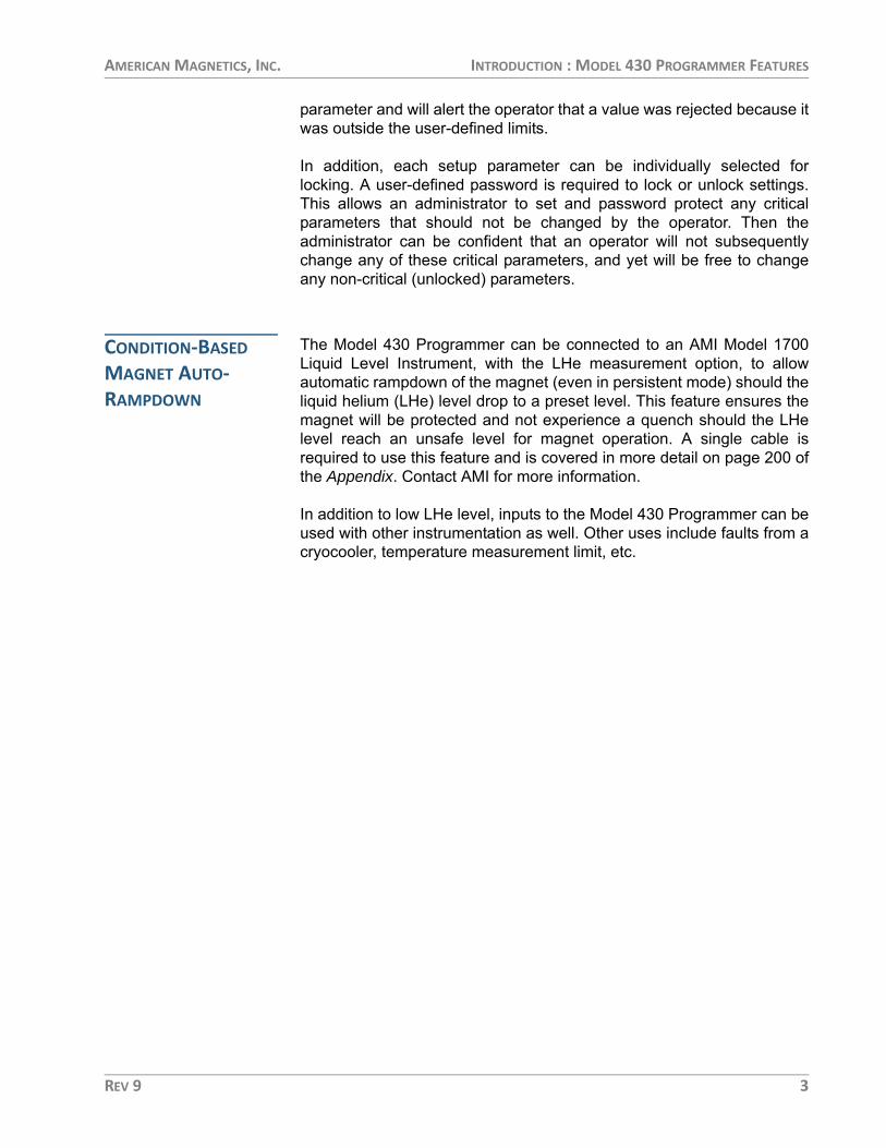
CONDITION-BASED MAGNET AUTO-RAMPDOWN
The Model 430 Programmer can be connected to an AMI Model 1700Liquid Level Instrument, with the LHe measurement option, to allowautomatic rampdown of the magnet (even in persistent mode) should theliquid helium (LHe) level drop to a preset level. This feature ensures themagnet will be protected and not experience a quench should the LHelevel reach an unsafe level for magnet operation. A single cable isrequired to use this feature and is covered in more detail on page 200 ofthe Appendix. Contact AMI for more information.
In addition to low LHe level, inputs to the Model 430 Programmer can beused with other instrumentation as well. Other uses include faults from acryocooler, temperature measurement limit, etc.
REV 9 3

AMERICAN MAGNETICS, INC. INTRODUCTION : MODEL 430 FRONT PANEL LAYOUT
MODEL 430 FRONT PANEL LAYOUT
SH
IFT
12
3
45
78 .
+/-
0
96
RA
MP
RA
TE
INC
R.
FIE
LD
FIE
LDU
NIT
S
Vs
<> V
mV
OLT
ME
TE
RFI
NE
AD
JUS
T
P. S
WIT
CH
HT
R. C
UR
.S
TAB
.
DE
CR
.FI
ELD
FIE
LD <
>C
UR
RE
NT
VO
LTA
GE
LIM
ITR
ES
ET
QU
EN
CH
ME
NU
EN
TE
R
ES
C
PAU
SE
RA
MP
TAR
GE
TFI
ELD
SE
TP
OIN
T
PE
RS
IST.
SW
ITC
HC
ON
TR
OL
RA
MP
TOZ
ER
O
FIE
LD A
T T
AR
GE
TM
AG
NE
T I
N P
ER
SIS
TE
NT
MO
DE
MA
GN
ET
QU
EN
CH
CU
RR
EN
T L
EA
DS
EN
ER
GIZ
ED
Am
eric
an M
agne
tics,
Inc.
Mod
el 4
30Po
wer
Sup
ply
Prog
ram
mer
Mod
el 4
30 Fr
ont P
anel
Des
crip
tion
1Po
wer
Indi
cato
r LED
8Fi
ne A
djus
t Kno
b
228
0 x 1
6 Do
t Gra
phic
VF D
ispla
y9
Pers
isten
t Sw
itch
Heat
er C
ontr
ol K
ey
3Sh
ift In
dica
tor L
ED10
Targ
et F
ield
Set
poin
t Key
4Sh
ift K
ey11
Ram
p/Pa
use
Switc
h
54
Row
x 3
Colu
mn
Keyp
ad12
Men
u Na
viga
tion
and
Data
Ent
ry K
eys
6Po
wer
Sw
itch
13Ra
mp
to Z
ero
Key
7M
agne
t Sta
tus I
ndica
tor L
EDs
4 REV 9

AMERICAN MAGNETICS, INC. INTRODUCTION : MODEL 430 REAR PANEL LAYOUT
MODEL 430 REAR PANEL LAYOUT
Mod
el 4
30 R
esist
ive
Shun
t Ver
sion
Rear
Pan
el D
escr
iptio
n
1Cu
rren
t Shu
nt Te
rmin
als
6Au
x Inp
uts 1
5-pi
n Fe
mal
e HD
D-s
ub C
onne
ctor
2Et
hern
et R
J-45
Conn
ecto
r7
Dual
Aux
iliar
y LH
e Le
vel/T
emp
9-pi
n M
ale
D-su
b Co
nnec
tors
3RS
-232
9-p
in M
ale
D-su
b Co
nnec
tor
8Du
al M
agne
t Sta
tion
25-p
in Fe
mal
e D-
sub
Conn
ecto
rs
4Q
uenc
h I/O
15-
pin
Mal
e D-
sub
Conn
ecto
r9
Inpu
t Pow
er IE
C 60
320
C14
Mal
e Co
nnec
tor
5Pr
ogra
m O
ut 1
5-pi
n M
ale
D-su
b Co
nnec
tor
REV 9 5

AMERICAN MAGNETICS, INC. INTRODUCTION : MODEL 430 REAR PANEL LAYOUT
Mod
el 4
30 Ze
ro Fl
ux V
ersio
n Re
ar P
anel
Des
crip
tion
23
41
56
78
9
1Cu
rren
t Tra
nsdu
cer 9
-pin
Fem
ale
D-su
b Co
nnec
tor
6Au
x Inp
uts 1
5-pi
n Fe
mal
e HD
D-s
ub C
onne
ctor
2Et
hern
et R
J-45
Conn
ecto
r7
Dual
Aux
iliar
y LH
e Le
vel/T
emp
9-pi
n M
ale
D-su
b Co
nnec
tors
3RS
-232
9-p
in M
ale
D-su
b Co
nnec
tor
8Du
al M
agne
t Sta
tion
25-p
in Fe
mal
e D-
sub
Conn
ecto
rs
4Q
uenc
h I/O
15-
pin
Mal
e D-
sub
Conn
ecto
r9
Inpu
t Pow
er IE
C 60
320
C14
Mal
e Co
nnec
tor
5Pr
ogra
m O
ut 1
5-pi
n M
ale
D-su
b Co
nnec
tor
6 REV 9

AMERICAN MAGNETICS, INC. INTRODUCTION : MODEL 430 SPECIFICATIONS @ 25 °C
MODEL 430 SPECIFICATIONS @ 25 °C
Additional Model 430 Programmer Specifications
Magnet Current Control Parameters Standard Model 430 Factory Configurations: Programmable Limits
Imax: ±5 A ±10 A +100 A +120 A ±125 A +240 A ±250 A +300 A +600 A
Measurement Resolution (μA): 0.625 1.25 12.5 15.6 15.6 31.2 31.2 37.4 75.0
Accuracy (% of Imax): 0.04 0.04 0.04 0.04 0.04 0.04 0.04 0.005 0.005
Minimum Ramp Rate (μA/min)a: 3 6 60 75 75 150 150 18 36
Maximum Ramp Rate (A/sec): 0.5 1 10 12.5 12.5 25 25 30 60
a. Minimum ramp rate is 1/10th of the listed value with the high-stability option installed for systems up to ±250 A. Systems with higher maximum current capacity include the high-stability option as standard.
Magnet Current ControlTemperature Coefficient: 0.01% of Imax / °C
Stability (w/ internal shunt):
w/ High-Stability Option:
With standard internal shunt, better than 0.002% of Imax after 20 minutes at desired current With High-Stability Option (zero flux current transducer), better than 0.001% of Imax after 10 minutes at desired current
Noise Floor Relative to Imax: −127 dB w/ internal shunt, −138 dB with High-Stability Option
Target Setpoint Entry Precision: 15 digitsa
Ramp Rate Entry Precision: 15 digitsa
Nominal Load Inductance Range: 0.05 to 200 H (extended range of 0.01 to 1000 H available)
Program Out VoltageProgrammable Limits: −10 to +10 VDC
Accuracy: 3 mV (0.03% of Vmax)
Temperature Coefficient: 0.2 mV / °C (0.002% of Vmax / °C)
Resolution: 0.3 mVStability: Better than 10 mV p-p when paused or holding
(with 0.05 to 200 H load)
Magnet Voltage MeasurementMaximum Limits: −20 to +20 VDC
Accuracy: 20 mV (0.1% of Vmax / °C)
Temperature Coefficient: 1.5 mV / °C (0.0075% of Vmax / °C)
Resolution: 10 mV
REV 9 7

AMERICAN MAGNETICS, INC. INTRODUCTION : MODEL 430 SPECIFICATIONS @ 25 °C
Persistent Switch Heater OutputProgrammable Limits: 0.0 to 100 mA DC
Accuracy: 0.2 mATemperature Coefficient: 0.01 mA / °C
Maximum Compliance: 14 VResolution: 0.03 mA
Rampdown and Quench InputsOpen Circuit Voltage: 5 VDC ±5%
Input Resistance: 10 kΩ ±1%
Quench Dry Contact OutputMaximum Switching Voltage: 60 VDC
Maximum Switching VA: 10 VAMaximum Switching Current: 500 mA, unless limited by VA rating
Galvanic Isolation: 125 VDC
Power RequirementsPrimary: 100-115 VAC or 200-230 VAC ±10%
50 / 60 Hz, 100 VA max., 30 W max.Real-time Clock Backup Battery: 3 V CR2032 Lithium coin cell
PhysicalDimensions: 89 mm H x 483 mm W x 191 mm D
(3.5" H x 19" W x 10.75" D)Weight: 8.5 lbm (3.9 kg)
Terminal Torque Limit: 48 in-lb (5.4 N-m)
EnvironmentalAmbient Temperature: Operating: 0 °C to 50 °C (32 °F to 122 °F)
Nonoperating: −20 °C to 70 °C (−4 °F to 158 °F)Relative Humidity: 0 to 95%; non-condensing
StandardsEMI/EMC Standards: EN 61000-4-2 EN 61000-4-3
EN 61000-4-4 EN 61000-4-5EN 61000-4-6 EN 61000-4-8EN 61000-4-11 EN 61000-3-2EN 61000-3-3 EN 55011
Safety Standard: EN61010-1Installation Category: Pollution Degree 2, Overvoltage Category II as defined by IEC664
a. Resolution of the IEEE 754 double-precision floating point type consisting of a 52-bit fraction and 11-bit exponent. Actual controlled accuracy and resolution depend upon the specific load configuration and hardware performance lim-its.
8 REV 9

AMERICAN MAGNETICS, INC. INTRODUCTION : OPERATING CHARACTERISTICS
OPERATING CHARACTERISTICS
The Model 430 Programmer has been designed to perform with variouspower supplies to allow the user the greatest degree of system flexibility.The power supply and Programmer combination are categorized by oneof three forms: single-quadrant, dual-quadrant, and four-quadrant. Forsake of clarity, the term quadrant is defined as one of four areas of acartesian coordinate system where the abscissa is current and theordinate is voltage. Refer to the figure below:
NOTE The resistive current measurement shunt in the following system diagrams, which is internal to the Model 430 chassis, can be optionally replaced with an external high-stability, precision zero flux current measurement device for additional cost. This is termed the “High-Stability” option for AMI power supply systems.
SINGLE-QUADRANT OPERATION
The simplest form of a Programmer-Power Supply system is the single-quadrant system as illustrated in the figure at the top of the followingpage. The system is composed of a Model 430 Programmer, unipolarpower supply, and superconducting magnet.
This system allows current to flow in a single direction in the magnetthereby giving a magnetic field vector of varying magnitude but in asingle direction. This corresponds to operating in quadrant N. The
20
-20
200-200
V
I
Positive CurrentFlow Direction
Positive VoltagePolarity
Positive CurrentFlow Direction
Negative VoltagePolarity
Negative CurrentFlow Direction
Positive VoltagePolarity
Negative CurrentFlow Direction
Negative VoltagePolarity
12
43
The Four Regions, or Quadrants, of System Operation
REV 9 9

AMERICAN MAGNETICS, INC. INTRODUCTION : OPERATING CHARACTERISTICS
electrical energy can be stored as magnetic energy as fast as themagnet and power supply voltage will allow.
In order to reduce the magnetic field, the magnetic energy is convertedto electrical energy and then to thermal energy in the resistive elementsof the system. The magnitude of the resistive elements determines howfast the magnetic field can be collapsed and is typically very slow in thesingle-quadrant system. AMI does not recommend single-quadrantoperation with large inductive loads due to the extremely long dischargetimes involved.
DUAL-QUADRANT OPERATION
In the Bipolar Power Supply System, an energy absorber is added inseries with the unipolar supply; this allows stored magnetic energy to beconverted to thermal energy, thereby allowing much faster magnetic fieldreduction. This corresponds to operation in quadrants N and Q,referring to the figure on page 9.
The disadvantage to this type of system is that energy is beingdissipated in the energy absorbing element whenever current is flowing.
Single-Quadrant System with Resistive Shunt
MagnetCoil(s)
PersistentSwitch
(optional)
Misc. Line Losses
Model 430Shunt
VUnipolarPower Supply
Current
MagnetCoil(s)
PersistentSwitch
(optional)
Misc. Line Losses
Model 430Shunt
EnergyAbsorber
VUnipolarPower Supply
Current
Dual-Quadrant (Bipolar) System with Resistive Shunt
10 REV 9

AMERICAN MAGNETICS, INC. INTRODUCTION : OPERATING CHARACTERISTICS
This loss is sometimes a significant portion of the power required tooperate the system. It also does not provide for field polarity reversal.
FOUR-QUADRANT OPERATION
The Four-Quadrant Magnet Power Supply System illustrated in thefigure below offers the most control of all the modes of operation.Efficiency is increased and reversible magnetic field profiles areattainable without discontinuities in the current. The magnetic energysink returns a significant portion of the power to the AC line instead ofdissipating it as heat.
Disadvantages of the four-quadrant system include somewhat increasedcost of the power supply over unipolar power supplies or bipolar powersupply systems, and added complexity in protecting the power supply inthe event of AC power loss or magnet quenching. Nonetheless, modernfour-quadrant power supplies which include integral output protectionagainst AC power loss and magnet quenching are available atreasonable prices.
MagnetCoil(s)
PersistentSwitch
(optional)
Misc. Line Losses
Model 430Shunt
VFour-QuadrantPower Supply
Current
Four-Quadrant System with Resistive Shunt
REV 9 11

AMERICAN MAGNETICS, INC. INTRODUCTION : OPERATING CHARACTERISTICS
12 REV 9

AMERICAN MAGNETICS, INC. INSTALLATION
Installation WARNING Before energizing the equipment, the earth ground of the
power receptacle must be verified to be at earth potential and able to carry the rated current of the power circuit. Using extension cords should be avoided; however, if one must be used, ensure the ground conductor is intact and capable of carrying the rated current.
WARNING In the event that the ground path becomes less than sufficient to carry the rated current of the power circuit, the equipment should be disconnected from power, labeled as unsafe, and removed from place of operation.
WARNING Do not operate this equipment in the presence of flammable gases. Doing so could result in a life-threatening explosion.
WARNING Do not modify this equipment in any way. If component replacement is required, return the equipment to AMI facilities as described in the Service section of this manual.
WARNING If used in a manner not specified in this manual, the protection provided by the design, manufacture and documentation of the Model 430 Programmer may be impaired.
REV 9 13

AMERICAN MAGNETICS, INC. INSTALLATION : INSPECTING AND UNPACKING
INSPECTING AND UNPACKING
Carefully remove the equipment, interconnecting cabling, anddocumentation CD (and/or printed material) from the shipping carton,and remove all packaging material.
NOTE If there is any shipping damage, save all packing material and contact the shipping representative to file a damage claim. Do not return to AMI unless prior authorization has been received.
MODEL 430 PROGRAMMER
If the Model 430 Programmer system is to be used on a table top, placeit on a flat, secure surface capable of handling the weight. The Model430 Programmer uses an internal fan for forced-air cooling. Allow atleast 1/2 inch spacing on each side of the unit for proper ventilation.
WARNING Do not remove the cabinet feet and then reinsert the original screws. Doing so could present a severe, life-threatening electrical hazard. If the cabinet feet are removed, do not reinstall the screws. If screws must be installed where the feet were mounted, replace the original screws with screws not to exceed 1/4 inch in length.
If the Model 430 Programmer is to be rack mounted, install it in a 19"wide instrument rack using the mounting hardware supplied by the rackcabinet manufacturer. Secure the front panel to the rail in each of thefour corners.
POWER REQUIREMENTS
WARNING The Model 430 Programmer operates on 50/60 Hz power and may be configured for 100-115 VAC or 200-230 VAC. The power requirement is marked on the rear panel adjacent to the power entry connector. Be sure the Model 430 Programmer is configured for the power source prior to plugging in the line cord. Do not fail to connect the input ground terminal securely to an external earth ground.
14 REV 9

AMERICAN MAGNETICS, INC. INSTALLATION : POWER REQUIREMENTS
CAUTION If the system includes the High-Stability Option, operating the system without power applied to the current transducer (CT) can result in loss of control, and may damage the CT.
NOTE AMI recommends energizing the Model 430 Programmer from the same power source as the power supply to be controlled. Since both the Programmer and the power supply are floating, if the ground potentials of the Programmer 115 VAC outlet and the Power Supply 230 VAC outlet different, an AC ground loop can form which can cause control anomalies. Refer to following section if the line voltage needs to be changed to 230 VAC.
Ensure the front panel power switches are in the O (OFF) position. Verifythat the Model 430 Programmer and power supply component(s) areconfigured for the proper operating voltage by referring to the labeladjacent to the power entry connector on the equipment rear panels. Ifthe operating voltage is correct, plug the line cords into the power entryconnectors, and then into the appropriate facility power receptacles.
CHANGING THE MODEL 430 PROGRAMMER OPERATING VOLTAGE
WARNING The following procedure is to be performed only when the Model 430 Programmer is completely de-energized by removing the power-cord from the power receptacle. Failure to do so could result in personnel coming in contact with high voltages capable of producing life-threatening electrical shock.
NOTE The voltage selector switch is labeled “115” for nominal line voltages from 100 to 115 VAC. The switch is labeled “230” for nominal line voltages of 200 to 230 VAC.
If the Model 430 Programmer operating voltage must be changed,ensure the instrument is de-energized by disconnecting the power cordfrom the power source. Remove the Model 430 Programmer cover byremoving the four screws on both sides of the cover and the four screwsfrom the corners of the cover on the back panel; slide the voltageselector switch on the main printed circuit board to the proper voltage.Replace the Model 430 Programmer cover.
REV 9 15

AMERICAN MAGNETICS, INC. INSTALLATION : COLLECTING NECESSARY INFORMATION
COLLECTING NECESSARY INFORMATION
In order to properly configure the Model 430 Programmer, specificsystem information is required. Such parameters as the magnetelectrical properties, type of power supply, persistent switch heatingcurrent requirements, and voltage and current constraints of the magnetare entered into the Model 430 Programmer once and nonvolatilememory will retain the data even after power is removed from theinstrument. An example of the data to be entered and how it is entered isdescribed on page 108.
If the Model 430 Programmer was purchased as part of a magnetsystem, essential data will have already been entered at the AMI factoryand a configuration sheet will have been provided detailing the settings.
SYSTEM INTERCONNECTS (SINGLE-AXIS SYSTEMS1)
If the Model 430 Programmer was purchased as part of a magnetsystem, all applicable system components and wiring harnesses willhave been shipped with the system. Since many different configurationsare possible, use the system interconnection diagram that most closelymatches your system; this is usually determined by the operatingcharacteristics of the power supply.
For maximum immunity to AC line noise, ensure that the chassis of theModel 430 Programmer has a direct, low impedance electricalconnection to the chassis of the power supply to which the PROGRAMOUT is connected. The connection can be made via a grounding strap,or if rack mounted, through the rack itself if it is constructed ofelectrically-conductive material.
The system diagrams that follow will assist in system equipmentconnections.
CAUTION The wiring between the power supply and the magnet current leads must be of sufficient size to carry the full rated current of the power supply. Typically, for short runs (less than 25 ft, or 7.6 m), 2 AWG wire is sufficient for 125 A current, and 2/0 AWG wire is best for 250 A current. Consult with an AMI Technical Support Representative for higher current applications.
1. For additional multi-axis system details, refer the information on page 37.
16 REV 9

AMERICAN MAGNETICS, INC. INSTALLATION : SYSTEM INTERCONNECTS (SINGLE-AXIS SYSTEMS)
Note that an AMI Model 1700 Liquid Level Instrument (with the LHemeasurement option) is shown as a possible component of eachintegrated system. The main instrumentation cable connecting themagnet support stand to one of the Model 430 Programmer MAGNETSTATION connectors contains all the instrumentation and controlconnections needed to control and monitor the magnet. The signals inthis cable which are required to monitor LHe level and temperatures arealso presented at the LHe Level/Temp Connectors. Refer to theAppendix for pin-outs of these and other connectors.
REV 9 17

AMERICAN MAGNETICS, INC. INSTALLATION : SYSTEM INTERCONNECTS (SINGLE-AXIS SYSTEMS)
UNIPOLAR POWER SUPPLY SYSTEM
The Model 430 Programmer can be used in the single-quadrant mode.The magnet power supply system consists of the Model 430, a unipolarpower supply and associated interconnection cabling. AMI does notrecommend single-quadrant operation with large inductive, high-currentloads due to the extremely long discharge times involved.
The diagram on page 19 shows this integrated system. Ensure thecabling is connected in the following manner:
NOTE The use of locking hardware is recommended for all high-current connections.
WARNING Ensure the protective diode is installed across the output terminals of the power supply with the anode at the negative (–) terminal and the cathode at the positive (+) terminal. Removal or omission of this protective diode may cause serious injury to personnel and damage to the power supply under loss of AC power conditions.
a. Connect the protective diode across the output terminals of the power supply: anode to the negative (–) terminal and the cathode to the positive (+) terminal.
b. Connect the positive (+) power supply terminal ì to the positive magnet current lead î.
c. Connect the negative magnet current lead ï to the positive (+) resistive shunt terminal ñ on the back of the Model 430 Programmer.
CAUTION Do not overtighten the hardware on the interconnection terminals (refer to specifications table on page 8 for torque limits). Overtightening can result in damage to the terminals.
d. Connect the negative (−) resistive shunt terminal ó on the back of the Model 430 Programmer to the negative (–) power supply terminal r.
e. Connect two jumpers ~â from terminal block position S- to M- and from S+ to M+.
f. Connect the DB15 analog I/O cable from the ANALOG I/O connector on the rear of the power supply s to the PROGRAM OUT connector ~ã on the back of the Model 430 Programmer.
18 REV 9

AMERICAN MAGNETICS, INC. INSTALLATION : SYSTEM INTERCONNECTS (SINGLE-AXIS SYSTEMS)
AM
ERIC
AN
MAG
NET
ICS,
INC.
OA
K RI
DG
E,TN
, USA AU
X I/O
RS-2
32ET
HER
NET
VALV
ECO
NTR
OL
O/T
LHe
100-
240V
ac50
-60
Hz
200
VA
Unip
olar
Syst
em In
terc
onne
ctio
ns
REV 9 19

AMERICAN MAGNETICS, INC. INSTALLATION : SYSTEM INTERCONNECTS (SINGLE-AXIS SYSTEMS)
g. Install an instrumentation cable between the magnet support stand top plate connector t and one of the MAGNET STATION connectors ~ç on the rear of the Model 430 Programmer.
h. Optional: Install an instrumentation cable between one of the LHe LEVEL / TEMP connectors ~å on the rear of the Model 430 Programmer and the Model 1700 Liquid Level Instrument LHe connector and/or temperature instrument u. Refer to page 195.
i. Optional: Install an instrumentation cable between the QUENCH I/O connector ~ä on the rear of the Model 430 Programmer and Aux I/O connector on the rear panel of the Model 1700 Liquid Level Instrument ~í. Refer to page 200.
j. Connect each device line cord from the respective device to the appropriate power receptacle.
k. Remote communications via Ethernet and/or RS-232 can be accomplished by connecting suitable cabling to the Model 430 Programmer rear panel ETHERNET and/or RS-232 connectors.
20 REV 9

AMERICAN MAGNETICS, INC. INSTALLATION : SYSTEM INTERCONNECTS (SINGLE-AXIS SYSTEMS)
BIPOLAR POWER SUPPLY SYSTEM
For the bipolar (dual-quadrant) mode with shunt method of currentsensing, the magnet power supply system consists of the Model 430Programmer, one or more unipolar 08150PS power supplies (eachtypically configured for +10 VDC/120 A output), and one or more Model601 Energy Absorber with associated interconnection cabling andbuswork.
Referring to the diagram on page 22, ensure the cabling is connected inthe following manner:
NOTE The use of locking hardware is recommended for all high-current connections.
CAUTION Do not overtighten the hardware on the interconnection terminals (refer to specifications table on page 8 for torque limits). Overtightening can result in damage to the terminals.
WARNING Ensure the protective diode is installed across the output terminals of the power supply with the anode at the negative (–) terminal and the cathode at the positive (+) terminal. Removal or omission of this protective diode may cause serious injury to personnel and damage to the power supply under loss of AC power conditions.
a. Connect the protective diode between the output terminals of the power supply: anode to the negative (–) terminal and the cathode to the positive (+) terminal.
b. Connect the positive (+) output terminal ì of the power supply to the Model 601 Energy Absorber positive (+) terminal î.
c. Connect the negative (−) terminal ï of the Model 601 Energy Absorber to the positive (+) magnet current lead ñ.
d. Connect the negative (−) magnet current lead ó to the positive (+) resistive shunt terminal r on the back of the Model 430 Programmer.
e. Connect the negative (−) resistive shunt terminal s of the Model 430 Programmer to the negative (–) output terminal of the power supply t.
f. Connect two jumpers ~è from terminal block position S- to M- and from S+ to M+ on the power supply unit.
REV 9 21

AMERICAN MAGNETICS, INC. INSTALLATION : SYSTEM INTERCONNECTS (SINGLE-AXIS SYSTEMS)
AM
ERIC
AN
MAG
NET
ICS,
INC.
OA
K RI
DG
E,TN
, USA AU
X I/O
RS-2
32ET
HER
NET
VALV
ECO
NTR
OL
O/T
LHe
100-
240V
ac50
-60
Hz
200
VA
Mod
el 0
5100
PS-0
5120
PS-4
30-6
01 B
ipol
ar Sy
stem
Inte
rcon
nect
ions
22 REV 9

AMERICAN MAGNETICS, INC. INSTALLATION : SYSTEM INTERCONNECTS (SINGLE-AXIS SYSTEMS)
g. Connect the DB15 analog I/O cable from the PROGRAM OUT connector ~å on the back of the Model 430 Programmer to the DB15 ANALOG I/O connector u on the rear of the power supply unit.
h. Install an instrumentation cable between the magnet support stand top plate connector ~í and one of the MAGNET STATION connectors ~é on the rear of the Model 430 Programmer.
i. Optional: Install an instrumentation cable between one of the LHe LEVEL / TEMP connectors ~ç on the rear of the Model 430 Programmer and the Model 1700 Liquid Level Instrument LHe connector and/or temperature instrument ~â. Refer to page 195.
j. Optional: Install an instrumentation cable between the QUENCH I/O connector ~ã on the rear of the Model 430 Programmer and Aux I/O connector ~ä on the rear panel of the Model 1700 Liquid Level Instrument. Refer to page 200.
k. Connect Model 601 power adapter Äâ and device line cords, and plug them into appropriate power receptacles.
l. Remote communications via Ethernet and/or RS-232 can be accomplished by connecting suitable cabling to the Model 430 Programmer rear panel ETHERNET and/or RS-232 connectors.
REV 9 23

AMERICAN MAGNETICS, INC. INSTALLATION : SYSTEM INTERCONNECTS (SINGLE-AXIS SYSTEMS)
HIGH-STABILITY BIPOLAR POWER SUPPLY SYSTEM
Current stability of the system can be increased by an order ofmagnitude through application of the zero flux method of currentsensing. For the bipolar (dual-quadrant) mode high-stability magnetpower supply, the system consists of the Model 430 Programmer withprecision current sensing, one or more unipolar 08150PS PowerSupplies and Model 601 Energy Absorbers, and associatedinterconnection cabling. The diagram on page 25 illustrates typicalinterconnects for the integrated bipolar high-stability magnet supplysystem.
Referring to the diagram on page 25, ensure the cabling is connected inthe following manner:
NOTE The use of locking hardware is recommended for all high-current connections.
CAUTION Do not overtighten the hardware on the interconnection terminals (refer to specifications table on page 8 for torque limits). Overtightening can result in damage to the terminals.
WARNING Ensure the protective diode is installed across the output terminals of the power supply with the anode at the negative (–) terminal and the cathode at the positive (+) terminal. Removal or omission of this protective diode may cause serious injury to personnel and damage to the power supply under loss of AC power conditions.
a. Connect ~ê the Model 601 parallel hardware bus between Model 601 current terminals, plus-to-plus and minus-to-minus.
b. Connect ~è the power supply parallel hardware bus between power supply current terminals, plus-to-plus and minus-to-minus.
c. Connect the protective diode between the output bus bars of the power supply: anode to the negative (–) terminal and the cathode to the positive (+) terminal.
d. Connect the positive (+) OUTPUT bus ì of the power supply to the positive (+) bus ~å of the Model 601 Energy Absorber(s).
NOTE When routing the magnet cable (+) from Model 601 negative (-) bus through the current transducer (CT), the current-direction arrow on the CT must point toward the magnet.
24 REV 9

AMERICAN MAGNETICS, INC. INSTALLATION : SYSTEM INTERCONNECTS (SINGLE-AXIS SYSTEMS)
AM
ERIC
AN
MAG
NET
ICS,
INC.
OA
K RI
DG
E,TN
, USA AU
X I/O
RS-2
32ET
HER
NET
VALV
ECO
NTR
OL
O/T
LHe
100-
240V
ac50
-60
Hz
200
VA
High
-Sta
bilit
y Bi
pola
r Sys
tem
Inte
rcon
nect
ions
REV 9 25

AMERICAN MAGNETICS, INC. INSTALLATION : SYSTEM INTERCONNECTS (SINGLE-AXIS SYSTEMS)
e. Connect the negative (−) bus ~ç of the Model 601 Energy Absorber(s) and route it through the CT (see note). Connect the other end to the positive (+) magnet current lead î.
f. Connect the negative magnet current lead ï to the negative power supply bus ó.
g. Connect Model 05100PS Master unit terminal block positions CS, S-, and S+ to each corresponding Slave terminal ~è. Connect Master to first Slave, first Slave to second Slave, etc.
h. Connect two jumpers ~é from terminal block position S- to M- and from S+ to M+ on the Master2 power supply unit.
i. Connect the current transducer output to the CURRENT TRANSDUCER connector ñ on the rear of the Model 430 Programmer.
j. Connect the special DB15 analog I/O cable from the PROGRAM OUT connector ~ã on the back of the Model 430 Programmer to the DB15 ANALOG I/O connectors on the rear of the Master r and each Slave ~ë power supply unit.
k. Install an instrumentation cable between the magnet support stand top plate connector s and one of the MAGNET STATION connectors ~í=on the rear of the Model 430 Programmer.
l. Optional: Install an instrumentation cable between one of the LHe / TEMP connectors u on the rear of the Model 430 Programmer and the Model 1700 Liquid Level Instrument LHe connector and/or temperature instrument t. Refer to page 195.
m.Optional: Install an instrumentation cable between the QUENCH I/O connector ~ä on the rear of the Model 430 Programmer and Aux I/O connector ~â on the rear panel of the Model 1700 Liquid Level Instrument. Refer to page 200.
n. Connect Model 601 power adapter Äí and device line cords, and plug them into appropriate power receptacles.
o. On the rear of each parallel Model 601 Energy Absorber, interconnect BNC coaxial connectors Äâ with coaxial cables. If more than two units are connected in parallel, use standard BNC “T” adapters on the inner units. The “end” units should be connected directly to the coaxial cable — no BNC terminators should be used.
2. Do not add terminal block jumpers to the slave units. Only the single or master unit is jum-pered.
26 REV 9

AMERICAN MAGNETICS, INC. INSTALLATION : SYSTEM INTERCONNECTS (SINGLE-AXIS SYSTEMS)
p. Remote communications via Ethernet and/or RS-232 can be accomplished by connecting suitable cabling to the Model 430 Programmer rear panel ETHERNET and/or RS-232 connectors.
REV 9 27

AMERICAN MAGNETICS, INC. INSTALLATION : SYSTEM INTERCONNECTS (SINGLE-AXIS SYSTEMS)
HIGH-CURRENT FOUR-QUADRANT POWER SUPPLY SYSTEM
For a four-quadrant power supply system, the components include theModel 430 Programmer, the four-quadrant 4Q06125PS power supply,and associated interconnection cabling. The diagram on page 29illustrates the interconnects for the AMI Model 4Q06125PS-430 PowerSupply system.
Referring to the diagram on page 29, ensure the cabling is connected inthe following manner:
CAUTION For multi-axis systems3, ensure the power supply and magnet load cables are connected only to the equipment associated with the axis (Z-axis, Y-axis, or X-axis) for which the cable is labeled.
a. Connect the power supply OUTPUT terminal ì to the positive magnet current lead î.
NOTE The use of locking hardware is recommended for all high-current connections.
CAUTION Do not overtighten the hardware on the interconnection terminals (refer to specifications table on page 8 for torque limits). Overtightening can result in damage to the terminals.
b. Connect the negative magnet current lead ï to the positive (+) resistive shunt terminal ñ on the back of the Model 430 Programmer.
c. Connect the negative (−) resistive shunt terminal ó on the back of the Model 430 Programmer to the power supply COMMON terminal r.
d. Connect the DB15 cable from the PROGRAM OUT connector ~ä on the back of the Model 430 Programmer to the ANALOG I/O connector s on the rear of the power supply.
e. Install an instrumentation cable between the magnet support stand top plate connector t and one of the MAGNET STATION connectors ~å on the rear of the Model 430 Programmer.
f. Optional: Install an instrumentation cable between one of the LHe LEVEL / TEMP ~ã connectors on the rear of the Model 430
3. Refer to page 37.
28 REV 9

AMERICAN MAGNETICS, INC. INSTALLATION : SYSTEM INTERCONNECTS (SINGLE-AXIS SYSTEMS)
AM
ERIC
AN
MAG
NET
ICS,
INC.
OA
K RI
DG
E,TN
, USA AU
X I/O
RS-2
32ET
HER
NET
VALV
ECO
NTR
OL
O/T
LHe
100-
240V
ac50
-60
Hz
200
VA
Mod
el 4
Q061
25PS
-430
Syst
em In
terc
onne
ctio
ns
REV 9 29

AMERICAN MAGNETICS, INC. INSTALLATION : SYSTEM INTERCONNECTS (SINGLE-AXIS SYSTEMS)
Programmer and the Model 1700 Liquid Helium Level Instrument LHe connector and/or temperature instrument u. Refer to page 195.
g. Optional: Install an instrumentation cable between the QUENCH I/O connector ~â on the rear of the Model 430 Programmer and Aux I/O connector ~í on the rear panel of the Model 1700 Liquid Level Instrument. Refer to page 200.
h. Connect each device line cord from the respective device to the appropriate power receptacle.
i. Remote communications via Ethernet and/or RS-232 can be accomplished by connecting suitable cabling to the Model 430 Programmer rear panel ETHERNET and/or RS-232 connectors.
30 REV 9

AMERICAN MAGNETICS, INC. INSTALLATION : SYSTEM INTERCONNECTS (SINGLE-AXIS SYSTEMS)
HIGH-CURRENT, HIGH-STABILITY 4-QUADRANT POWER SUPPLY SYSTEM
Current stability of the system can be increased by an order ofmagnitude through application of the zero flux method of currentsensing. For the high-stability four-quadrant high-current power supplysystem, the components include the Model 430 Programmer, a four-quadrant power supply (typically an AMI Model 4Q06125PS), a precisioncurrent sensing system, and associated interconnecting cabling. Thediagram on page 32 illustrates the interconnects for a High-StabilityModel 4Q06125PS-430 power supply.
Referring to the diagram on page 32, ensure the cabling is connected inthe following manner:
NOTE The use of locking hardware is recommended for all high-current connections.
CAUTION Do not overtighten the hardware on the interconnection terminals (refer to specifications table on page 8 for torque limits). Overtightening can result in damage to the terminals.
NOTE If routing the magnet cable (+) from power supply OUTPUT through the current transducer (CT), the current-direction arrow on the CT must point toward the magnet.
a. Connect the OUTPUT power supply terminal ì and route it through the zero flux current transducer (see note). Connect the other end to the positive magnet current lead î.
b. Connect the negative magnet current lead ï to the COMMON power supply terminal ó.
c. Connect the CT output to the current transducer CURRENT TRANSDUCER connector ñ on the rear of the Model 430 Programmer.
d. Connect the DB15 cable from the PROGRAM OUT connector ~ã on the back of the Model 430 Programmer to the ANALOG I/O connector r=on the rear of the power supply.
e. Install an instrumentation cable between the magnet support stand top plate connector s and one of the MAGNET STATION connectors ~í on the rear of the Model 430 Programmer.
f. Optional: Install an instrumentation cable between one of the LHe / TEMP connectors u=on the rear of the Model 430 Programmer and
REV 9 31

AMERICAN MAGNETICS, INC. INSTALLATION : SYSTEM INTERCONNECTS (SINGLE-AXIS SYSTEMS)
AM
ERIC
AN
MAG
NET
ICS,
INC.
OA
K RI
DG
E,TN
, USA AU
X I/O
RS-2
32ET
HER
NET
VALV
ECO
NTR
OL
O/T
LHe
100-
240V
ac50
-60
Hz
200
VA
Mod
el 4
Q061
25PS
-430
Hig
h-St
abili
ty Sy
stem
Inte
rcon
nect
s
32 REV 9

AMERICAN MAGNETICS, INC. INSTALLATION : SYSTEM INTERCONNECTS (SINGLE-AXIS SYSTEMS)
the Model 1700 Liquid Level Instrument LHe input and/or temperature instrument t. Refer to page 195.
g. Optional: Install an instrumentation cable between the QUENCH I/O connector ~ä on the rear of the Model 430 Programmer and Aux I/O connector ~â=on the rear panel of the Model 1700 Liquid Level Instrument. Refer to page 200.
h. Connect each device line cord from the respective device to the appropriate power receptacle.
i. Remote communications via Ethernet and/or RS-232 can be accomplished by connecting suitable cabling to the Model 430 Programmer rear panel ETHERNET and/or RS-232 connectors.
REV 9 33

AMERICAN MAGNETICS, INC. INSTALLATION : SYSTEM INTERCONNECTS (SINGLE-AXIS SYSTEMS)
LOW-CURRENT, HIGH-RESOLUTION 4-QUADRANT POWER SUPPLY SYSTEM
AMI offers a low-current (5 A or 10 A rated) system option to achievehigh-resolution control of the magnet current. The components include aModel 430 Programmer, a Model 4Q1005PS or Model 4Q1010PS low-current four-quadrant power supply, and associated interconnectingcabling. The diagram on page 35 illustrates the interconnects for the low-current integrated power supply system.
NOTE Due to continuous discharge power limitations present in the BOP series supplies, for maximum safety AMI limits both the charging and discharging voltage, via the Model 430 Programmer, to a maximum of 10 volts.
CAUTION Do not overtighten the hardware on the interconnection terminals (refer to specifications table on page 8 for torque limits). Overtightening can result in damage to the terminals.
Referring to the diagram on page 35, ensure the cabling is connected inthe following manner:
a. Connect the OUT power supply terminal ì to the positive magnet current lead î.
b. Install three jumpers on the terminal board (back of power supply):
S OUT to OUTGRD NET to COMCOM to S COM.
c. Connect the negative magnet current lead ï to the positive (+) resistive shunt terminal ñ on the back of the Model 430 Programmer.
d. Connect the negative (−) resistive shunt terminal ó on the back of the Model 430 Programmer to the COM power supply terminal r.
e. Connect the DB15 end of the program cable to the PROGRAM OUT connector ~ã on the back of the Model 430 Programmer. Connect the other end (the 50-pin edge connector) to the rear of the power supply s.
f. Install an instrumentation cable between the magnet support stand top plate connector t and one of the MAGNET STATION connectors ~ç on the rear of the Model 430 Programmer.
g. Optional: Install an instrumentation cable between one of the LHe LEVEL / TEMP connectors ~å on the rear of the Model 430
34 REV 9

AMERICAN MAGNETICS, INC. INSTALLATION : SYSTEM INTERCONNECTS (SINGLE-AXIS SYSTEMS)
AM
ERIC
AN
MAG
NET
ICS,
INC.
OA
K RI
DG
E,TN
, USA AU
X I/O
RS-2
32ET
HER
NET
VALV
ECO
NTR
OL
O/T
LHe
100-
240V
ac50
-60
Hz
200
VA
Mod
el 4
Q100
5PS-
430
Low
-Cur
rent
Syst
em In
terc
onne
ctio
ns
REV 9 35

AMERICAN MAGNETICS, INC. INSTALLATION : SYSTEM INTERCONNECTS (SINGLE-AXIS SYSTEMS)
Programmer and the Model 1700 Liquid Level Instrument LHe connector and/or temperature instrument u. Refer to page 195.
h. Optional: Install an instrumentation cable between the QUENCH I/O connector ~ä on the rear of the Model 430 Programmer and Aux I/O connector ~â=on the rear panel of the Model 1700 Liquid Level Instrument. Refer to page 200.
i. Connect each device line cord from the respective device to the appropriate power receptacle.
j. Remote communications via Ethernet and/or RS-232 can be accomplished by connecting suitable cabling to the Model 430 Programmer rear panel ETHERNET and/or RS-232 connectors.
k. On the power supply front panel, set the MODE to VOLTAGE (to the left), and set both the VOLTAGE CONTROL and the CURRENT CONTROL switches to the OFF position (to the right).
36 REV 9

AMERICAN MAGNETICS, INC. INSTALLATION : SYSTEM INTERCONNECTS (MULTI-AXIS SYSTEMS)
SYSTEM INTERCONNECTS (MULTI-AXIS SYSTEMS)
GENERAL Each axis of AMI’s two and three axis superconducting magnet systemsincorporates a Model 430 Programmer, a four-quadrant power supply,and a set of power-supply and magnet interconnecting high-current loadcables. In addition, a combination of instruments to monitor or controltemperature, level, pressure and/or other parameters may be included.Actual instrumentation depends on the configuration and type of multi-axis system (standard helium-based, helium-recondensing, or cryogen-free).
LOAD CABLES Interconnecting high-current load cables are connected in the same wayas for a single axis system as described on page 28, or for the high-stability system on page 31. A separate set of cables is provided foreach axis of a multi-axis system; the cable device connection labelsinclude the associated axis (Z-axis, Y-axis, or X-axis).
For the high-stability system, as depicted in the diagram on page 32, thecurrent transducer is also duplicated for each axis along with the loadcables.
CAUTION For multi-axis systems, ensure the power supply and magnet load cables are connected only to the equipment associated with the axis for which the cable is labeled.
INSTRUMENTATION CABLES
Instruments such as level, temperature, pressure, etc. that are part ofthe system are typically not duplicated for each axis since they have thecapability to be switched among the various sensor and control devicesconnected to them. The instrumentation cables are designed todistribute the cryostat sensor and control signals to/from the associatedinstrument.
The Magnet Station Cable carries the signals between the cryostat andsystem rack equipment. For standard helium-based (non-recondensing)systems, the Magnet Station Cable connects directly to the Model 430Power Supply Programmer. However, for helium-recondensing orcryogen-free systems, the Magnet Station Cable connects to the Model430 through a distribution or breakout box. The temperature andpressure instruments have electrical signals that pass through thebreakout box. Refer to the illustrations that follow.
REV 9 37

AMERICAN MAGNETICS, INC. INSTALLATION : SYSTEM INTERCONNECTS (MULTI-AXIS SYSTEMS)
STANDARD (NON-RECONDENSING) HELIUM-BASED 2-AXIS SYSTEM SIGNAL INTERCONNECTS
î
ì
ï
ñ
AMERICAN MAGNETICS, INC.OAK RIDG E, TN, USA
AUX I/O
RS-232ETHERNET VALVE CONTROLO/T LHe
100-240Vac50-60 Hz
200 VA
Two-Axis Standard Helium System Signal Interconnections
38 REV 9

AMERICAN MAGNETICS, INC. INSTALLATION : SYSTEM INTERCONNECTS (MULTI-AXIS SYSTEMS)
STANDARD (NON-RECONDENSING) HELIUM-BASED 3-AXIS SYSTEM SIGNAL INTERCONNECTS
ó
î
ì
ï
ñ
AMERICAN MAGNETICS, INC.OAK RIDG E, TN, USA
AUX I/O
RS-232ETHERNET VALVE CONTROLO/T LHe
100-240Vac50-60 Hz
200 VA
Three-Axis Standard Helium System Signal Interconnections
REV 9 39

AMERICAN MAGNETICS, INC. INSTALLATION : SYSTEM INTERCONNECTS (MULTI-AXIS SYSTEMS)
RECONDENSING HELIUM-BASED 2-AXIS SYSTEM SIGNAL INTERCONNECTS
s
r
î
ì
ó
ï
ñ
t
AMERICAN MAGNETICS, INC.OAK RIDG E, TN, USA
AUX I/O
RS-232ETHERNET VALVE CONTROLO/T LHe
100-240Vac50-60 Hz
200 VA
Two-Axis Recondensing Helium System Signal Interconnections
40 REV 9

AMERICAN MAGNETICS, INC. INSTALLATION : SYSTEM INTERCONNECTS (MULTI-AXIS SYSTEMS)
RECONDENSING HELIUM-BASED 3-AXIS SYSTEM SIGNAL INTERCONNECTS
ï
t
s
î
ì
r
ñ
ó
u
AMERICAN MAGNETICS, INC.OAK RIDG E, TN, USA
AUX I/O
RS-232ETHERNET VALVE CONTROLO/T LHe
100-240Vac50-60 Hz
200 VA
Three-Axis Recondensing Helium System Signal Interconnections
REV 9 41

AMERICAN MAGNETICS, INC. INSTALLATION : SYSTEM INTERCONNECTS (MULTI-AXIS SYSTEMS)
CRYOGEN-FREE 2-AXIS SYSTEM SIGNAL INTERCONNECTS
CRYOGEN-FREE 3-AXIS SYSTEM SIGNAL INTERCONNECTS
ó
ì
ï
ñ
î
Two-Axis Cryogen-free System Signal Interconnections
r
î
ì
ñ
ó
ï
Three-Axis Cryogen-free System Signal Interconnections
42 REV 9

AMERICAN MAGNETICS, INC. INSTALLATION : THIRD-PARTY POWER SUPPLIES
THIRD-PARTY POWER SUPPLIES
The Model 430 Programmer has been designed to function with a widevariety of third-party power supplies. Please contact an AMI TechnicalSupport Representative for compatibility with specific models. Custommodifications can sometimes be made to accommodate supplies thatare not compatible with the standard Model 430 configurations.
SPECIAL CONFIGURATIONS
The Model 430 Programmer has been designed for optimal operationwith a superconducting magnet (i.e. a very low resistance, highinductance load) with a persistent switch. The Model 430 Programmer iscapable of controlling current to other loads; however, some modificationto the Model 430 Programmer settings and/or connections must usuallybe made. Two commonly encountered configurations are: 1)superconducting magnets without a persistent switch, and 2) operationon a short-circuit or low resistance load.
SUPERCONDUCTING MAGNETS WITH NO PERSISTENT SWITCH
An external stabilizing resistor for superconducting magnets without apersistent switch is no longer required4. However, electronicallystabilizing such magnets requires a filter that has a differentiating actionwhich can appear to amplify voltage noise across the magnet. If themagnet voltage noise, as indicated by Vm on the Model 430 statusscreen, is considered excessive for a user’s experiment, the user mayopt instead to use a stabilizing resistor.
OPTIONAL STABILIZING RESISTOR INSTALLATION
The stabilizing resistor, along with the proper Model 430 configuration,can reduce the apparent voltage noise across the magnet terminals byan order of magnitude or more.
To configure the Model 430 to use the stabilizing resistor, perform thefollowing steps:
4. Effective with Model 430 firmware version 1.62 or later.
REV 9 43

AMERICAN MAGNETICS, INC. INSTALLATION : SPECIAL CONFIGURATIONS
1. Place a 20 Ohm resis-tor, rated for 1W or higher, across the mag-net current leads at the top of the cryostat as shown in the figure at right.
2. Ensure the Model 430 is configured for no per-sistent switch installed (see page 83).
3. Use the STAB:RES 1 remote command (see page 154) to configure the Model 430 for oper-ation with the stablizing resistor.
Optionally use the Mag-net-DAQ application provided with the Model 430 to indicate a stabi-lizing resistor is installed (see page 226).
4. Ensure the Stability Setting (see page 79) is configured either by the Auto Stability Mode (see page 78), or by manually entering a Stability Setting per the recommendations for magnets with a persistent switch installed as shown on page 80.
SHORT-CIRCUIT OR RESISTIVE LOAD
If operating with a short-circuit as a load without the presence of asuperconducting magnet or with the power leads shorted at the cryostat,the Model 430 Programmer Stability Mode must be configured for Test(see page 78).
NOTE If you have purchased a superconducting magnet with the Model 430 Programmer, AMI will normally provide a recommended stability setting for optimal operation of the magnet system. If you operate the Model 430 Programmer with a different load, be sure to restore the Stability Mode and Stability Settings after testing to the AMI-recommended values when the superconducting magnet is reconnected.
A special test case is with the energy absorber designs available fromAMI connected to the system. The Model 601 Energy Absorber is anearly infinite-resistance device until 5 VDC is achieved across itsterminals. Once the 5 VDC “bias” is present, the Model 601 allows
Cryostat with Stabilizing Resistor acrossthe Magnet Current Leads
44 REV 9

AMERICAN MAGNETICS, INC. INSTALLATION : POWER-UP AND TEST PROCEDURE
current flow with a nominal 2 mΩ series resistance. Therefore, the Model430 Programmer will require an “integration time” to overcome the 5VDC bias. Once the bias is achieved, the series resistance is minimal,the Model 601 appears as a short-circuit, and test ramping will proceed.It is not possible to avoid this integration time.
However, when operating with a superconducting magnet in the circuit,the increased integration gain of the Model 430 Programmer will beadequate to quickly “bias” the Model 601 and achieve a proper currentramping profile. The only time the “integration time” is long is when anenergy absorber is connected, and the load is a short circuit.
POWER-UP AND TEST PROCEDURE
It is important to verify that the magnet system has been properlyconnected before the superconducting magnet is energized. This isespecially recommended if the system is to be controlled via a computersince this setup will allow software debugging without the potential fordamage to the magnet. The following procedures will assist the user inverifying key system components.
1. Using the appropriate diagram from the Installation section as a guide, verify all system components are connected as shown. If there is any doubt as to the correct connection of a component, contact an AMI Technical Support Representative. The user may be required to properly make a few connec-tions between the various system components which were disconnected to facilitate packing and shipping.
2. Temporarily place a short across the magnet current terminals. Often this is most easily accomplished by unfastening the heavy cables from the magnet current leads and fastening them together.5 This will allow rudimentary power supply checks without energizing the superconducting magnet.
NOTE It is important that the full length of the power leads to the magnet be connected during the Test mode since the leads provide some resistive load (albeit in the tens of mΩ range) for the power supply. The output current of a truly shorted supply output (i.e. zero resistance load) is very difficult to control in voltage mode and may be unstable.
3. Energize the Model 430 Programmer by placing the power switch in the I (ON) position.
5. If the system shipped with CamLoc quick-disconnect connectors, they may be quickly discon-nected from the magnet leads and connected together.
REV 9 45

AMERICAN MAGNETICS, INC. INSTALLATION : POWER-UP AND TEST PROCEDURE
NOTE If energy absorbers are in use, ensure all the power adapters are properly connected to the energy absorbers and their respective AC power receptacles.
4. When prompted by the Model 430 Programmer, energize the power sup-ply(s), allow an appropriate amount of time for the supply(s) to start (some produce an audible “click” during power-up), and then press ENTER on the Model 430 Programmer. If there is more than one power supply, observe the proper master/slave power-up procedure.
5. Configure the Model 430 Programmer for Test Stability Mode. Refer to page 78.
NOTE The Model 430 Programmer Stability Mode must be set to Test for the power supply system to be stable on a short circuit test load.
6. Verify the various setup menu values for the system. If the power supply sys-tem was purchased with an AMI magnet, AMI has preset the setup menu values for proper operation. See page 72 for more discussion of the setup menu values and their entry into the Model 430 Programmer.
7. Set the Target Setpoint to 10 A. Refer to page 54 and page 61.
8. Initiate ramping to the target current by pressing the RAMP / PAUSE key (status indicator changes from P to ).
9. The system should ramp to 10 A in approximately 2 seconds.6 Verify this is the case.
NOTE IfWith an energy absorber unit is connected, the Model 430 Programmer may take significantly longer to ramp the current to 10 A. The Model 430 must first develop a supply output voltage to overcome the forward voltage drop of a connected energy absorber. During actual magnet operation, the presence of an energy absorber will not significantly delay the ramping operation since the Model 430 control gain is increased by orders of magnitude when an inductive load is connected.
10.When the target current is achieved, the FIELD AT TARGET LED will be illuminated. The display should show “+10.00 A -” indicating that the Model 430 Programmer is in the holding mode at the target current value (+10.00 A).
11.If the connected power supply has a display, verify that the power supply out-put current display indicatess that a total of approximately 10 A is being sup-plied to the load (which is only the cabling in this case).
6. When controlling a magnet, the ramp is very accurate because the system gain is relatively high. When controlling current through a short-circuit, the loop gain is relatively low and it is difficult to track high ramp rates.
46 REV 9

AMERICAN MAGNETICS, INC. INSTALLATION : POWER-UP AND TEST PROCEDURE
NOTE There may be a discrepancy between the current shown on the power supply display7 and the current displayed on the Model 430 Programmer. The current measurement system incorporated in the Model 430 is more accurate than the power supply shunt.
12.Set the Target Setpoint to the Current Limit value. Refer to page 88 to deter-mine the Current Limit value. After the new Target Setpoint current value is entered, the Model 430 Programmer should ramp automatically to the new setting.
13.When the new target current value is reached, the power supply current dis-play (if provided) should also indicate the new value.
14.Press the RAMP TO ZERO key to ramp the system to zero current.
15.Perform remote control software checkout as required.
16.Turn off the power supply(s).
17.Reset the Stability Mode to Auto or Manual as appropriate for the magnet system to be operated and, if necessary, the parameters for an installed Per-sistent Switch. Then turn off the Model 430.
18.Remove the short from the power supply leads and connect the leads to the current leads on the cryostat.
After successful completion of this test, the system is ready for operationwith a superconducting magnet. Refer to the ramping function examplepresented on page 121 for a discussion of the various available rampingmethods.
7. Not all power supplies have a local current readout.
REV 9 47

AMERICAN MAGNETICS, INC. INSTALLATION : POWER-UP AND TEST PROCEDURE
48 REV 9
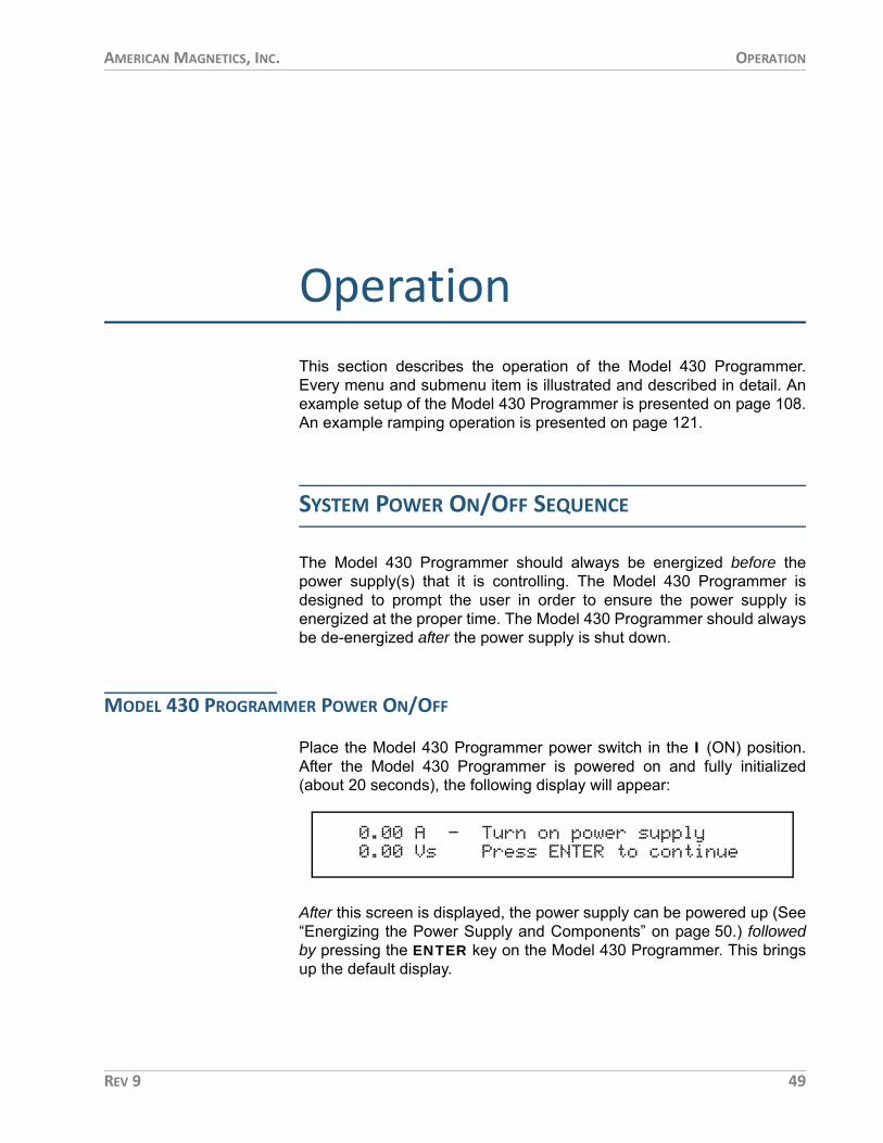
AMERICAN MAGNETICS, INC. OPERATION
OperationThis section describes the operation of the Model 430 Programmer.Every menu and submenu item is illustrated and described in detail. Anexample setup of the Model 430 Programmer is presented on page 108.An example ramping operation is presented on page 121.
SYSTEM POWER ON/OFF SEQUENCE
The Model 430 Programmer should always be energized before thepower supply(s) that it is controlling. The Model 430 Programmer isdesigned to prompt the user in order to ensure the power supply isenergized at the proper time. The Model 430 Programmer should alwaysbe de-energized after the power supply is shut down.
MODEL 430 PROGRAMMER POWER ON/OFF
Place the Model 430 Programmer power switch in the I (ON) position.After the Model 430 Programmer is powered on and fully initialized(about 20 seconds), the following display will appear:
After this screen is displayed, the power supply can be powered up (See“Energizing the Power Supply and Components” on page 50.) followedby pressing the ENTER key on the Model 430 Programmer. This bringsup the default display.
0.00 A - Turn on power supply 0.00 Vs Press ENTER to continue
REV 9 49

AMERICAN MAGNETICS, INC. OPERATION : SYSTEM POWER ON/OFF SEQUENCE
NOTE If the display instead appears as illustrated below, turn the Model 430 Programmer off, wait 15 seconds or more, and power the Model 430 Programmer back on.
When powering the system off, first turn off the power supply controlledby the Model 430 Programmer followed by the Model 430 Programmer.The controller will then ensure the load sees no abnormal powertransients as the power supply is turning off.
ENERGIZING THE POWER SUPPLY AND COMPONENTS
WARNING Do not change power supply jumpers, dip-switches, or other factory settings. If not rack-mounted, always position power supply(s) for convenience in disconnecting the power cords.
CHECK THE ZERO FLUX CURRENT TRANSDUCER
If the system includes the High-Stability Option, then a zero fluxcurrent transducer is provided. The current transducer must beconnected to the Model 430 rear panel CURRENTTRANSDUCER connector.
CAUTION Operating the system without power applied to the current transducer (CT) can result in loss of control, and may damage the CT.
The current transducer receives power from the Model 430Programmer through the CURRENT TRANSDUCER connection(that connects directly to the transducer) on the rear panel of theModel 430 Programmer.
ENERGIZING THE POWER SUPPLY
CAUTION The master unit must be turned on between 2 to 5 seconds before the slave, otherwise the units will fault and the power-up sequence will have to be repeated.
Place the power supply switches in the I (ON) position insequence (see Caution above). No front panel adjustments or
AMI Model 430 ProgrammerFAILURE TO LOAD.
50 REV 9
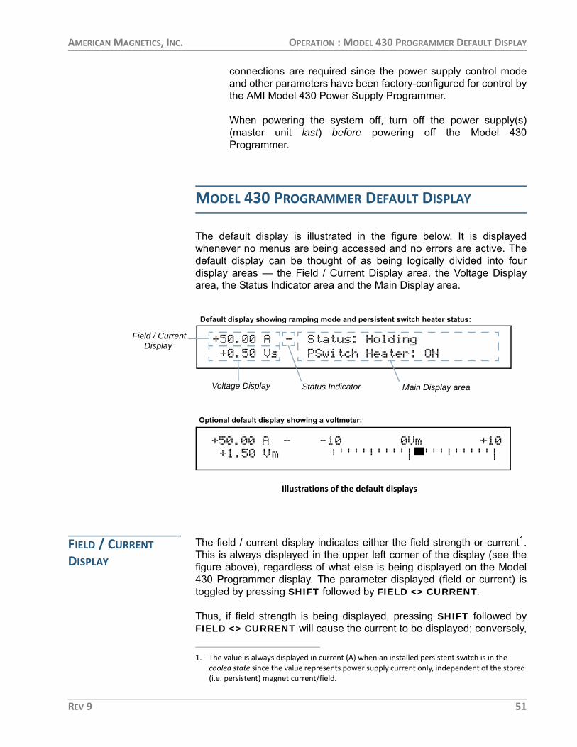
AMERICAN MAGNETICS, INC. OPERATION : MODEL 430 PROGRAMMER DEFAULT DISPLAY
connections are required since the power supply control modeand other parameters have been factory-configured for control bythe AMI Model 430 Power Supply Programmer.
When powering the system off, turn off the power supply(s)(master unit last) before powering off the Model 430Programmer.
MODEL 430 PROGRAMMER DEFAULT DISPLAY
The default display is illustrated in the figure below. It is displayedwhenever no menus are being accessed and no errors are active. Thedefault display can be thought of as being logically divided into fourdisplay areas — the Field / Current Display area, the Voltage Displayarea, the Status Indicator area and the Main Display area.
FIELD / CURRENT DISPLAY
The field / current display indicates either the field strength or current1.This is always displayed in the upper left corner of the display (see thefigure above), regardless of what else is being displayed on the Model430 Programmer display. The parameter displayed (field or current) istoggled by pressing SHIFT followed by FIELD <> CURRENT.
Thus, if field strength is being displayed, pressing SHIFT followed byFIELD <> CURRENT will cause the current to be displayed; conversely,
+50.00 A — Status: Holding +0.50 Vs PSwitch Heater: ON
+50.00 A — -10 0Vm +10+1.50 Vm |''''|''''|'''|'''''|
Field / Current
Default display showing ramping mode and persistent switch heater status:
Optional default display showing a voltmeter:
Illustrations of the default displays
Voltage Display Status Indicator Main Display area
Display
1. The value is always displayed in current (A) when an installed persistent switch is in the cooled state since the value represents power supply current only, independent of the stored (i.e. persistent) magnet current/field.
REV 9 51

AMERICAN MAGNETICS, INC. OPERATION : MODEL 430 PROGRAMMER DEFAULT DISPLAY
if current is being displayed, pressing SHIFT followed by FIELD <>CURRENT will cause the field strength to be displayed.
Operating current is always displayed in amperes (A). Operating fieldstrength may be displayed in kilogauss (kG) or tesla (T) if a coil constanthas been specified in the setup2. If field strength is being displayed, theunits (kG or T) in which it is displayed can be toggled by pressing SHIFTfollowed by FIELD UNITS.
NOTE The displayed field strength is not directly measured, but rather is calculated by multiplying the coil constant entered in the setup menu by the measured current flow of the Model 430 power supply system.
VOLTAGE DISPLAY The voltage display indicates either the voltage across the magnet (Vm)or the power supply output voltage (Vs). This is always displayed in thelower left corner of the display (see the figure on page 51), regardless ofwhat else is being displayed on the Model 430 Programmer display.
The parameter displayed (magnet voltage or power supply voltage) istoggled by pressing SHIFT followed by Vs <> Vm (i.e. SHIFT+0).
NOTE The right and left arrow keys can also be used to toggle the Voltage Display area to show the present temperature in Kelvin as optionally read via the Auxiliary Input 3. For more details, see page 91.
Vm indicates the voltage measured across the terminals of theconnected superconducting magnet. In order for the Model 430Programmer to measure the magnet voltage, the magnet voltage tapsmust be connected to the Model 430. Normally this is done through theMagnet Station Cable provided by AMI (if the whole magnet system isprovided by AMI). Vs indicates the Model 430 Programmer-controlledpower supply output voltage.
NOTE The displayed power supply voltage (Vs) is not directly measured, but rather is calculated based on power supply control voltage being provided by the Model 430 Programmer and the power supply input control voltage and output voltage values entered in the setup menu.
2. Refer to page 81.
52 REV 9

AMERICAN MAGNETICS, INC. OPERATION : MODEL 430 PROGRAMMER DEFAULT DISPLAY
STATUS INDICATOR The status indicator displaysthe Model 430 Programmeroperating status. It is alwaysvisible (except during a quenchcondition) and is displayed justto the right of the field / currentdisplay (see the figure onpage 51). The status indicatormay be one of the symbolsindicating a condition asdescribed in the table at left.
If the ramping mode characteris blank, then a quenchcondition exists and the redMAGNET QUENCH LED onthe front panel will beilluminated.
See page 110 for a more detailed discussion of the meaning of theramping modes (Paused, Ramping Up, Ramping Down and Holding).
MAIN DISPLAY The default main display (the rightmost portion of the display – see thefigure on page 51) shows either a voltmeter indicating magnet voltage orramp mode and persistent switch heater state. Ramp mode is displayedon the top line of the main display; it will be one of ten states, as listed inthe table on page 111.
The persistent switch heater state is displayed on the bottom line of themain display. If the Model 430 Programmer has been setup for use witha persistent switch, it will indicate either ON or OFF for the persistentswitch heater state; otherwise, it will display “No PSwitch Installed.”
Description of Status Indicators
P Paused
Ramping Up
Ramping Down
– Holding
Heating Persistent Switch
Cooling Persistent Switch
V Voltage Limited
C Current Limited
T Temperature Limited
REV 9 53

AMERICAN MAGNETICS, INC. OPERATION : ENTERING NUMERIC VALUES
ENTERING NUMERIC VALUES
A consistent method of entering values is used within menus requiringnumeric entries. Once a menu is selected, the user may start an entry bypressing a digit (0 through 9), the decimal key (.), or the sign key (+/-).3The display will begin a new entry and display a cursor (_) as a promptfor the next digit or decimal entry. Also, once entry is initiated, the displaywill show an asterisk (*) indicating that numeric entry is active.
Alternately, the ENTER key may be pressed before any of the numerickeypad keys; the display will begin a new entry and display a cursor (_)as a prompt for the next digit or decimal entry, and the display will showan asterisk (*) indicating that numeric entry is active.
An example of a numeric entry in progress (numeric entry active) isillustrated below:
Once the numeric value has been entered, press the ENTER key toaccept the numeric value. Values are not applied to the operation of theModel 430 Programmer until the ENTER key is pressed and the asteriskdisappears from the display. Attempts to set a parameter to a value
MENU
SHIFT
RAMPTO
ZERO
ENTER
ESC
1 2 3
4 5
7 8
. +/-0
9
6
RAMPRATE
INCR.FIELD
FIELDUNITS
Vs <> Vm VOLTMETER
FINEADJUST
P. SWITCHHTR. CUR. STAB.
DECR.FIELD
FIELD <>CURRENT
VOLTAGELIMIT
RESETQUENCH
Numeric Keypad and Associated Keys
3. Certain menu items requiring numeric data can also be entered using the fine adjust knob (see page 55).
+50.00 A - Target Current (A)*+0.50 Vs +74_
54 REV 9

AMERICAN MAGNETICS, INC. OPERATION : USING THE FINE ADJUST KNOB
outside of the valid range are ignored, and if attempted the Model 430Programmer will beep once, indicate the error, and revert to the previoussetting.
If the ESC key is pressed while numeric entry is active and digits havebeen entered, the entered digits will be cleared and the cursor willremain for reentry of a new desired value. If the ESC key is pressed withno entered digits on the display, the setting will revert to the previousvalue and numeric entry will be made inactive.
Thus, if digits have been entered, the first time ESC is pressed, theentered digits are cleared, but numeric entry remains active; if ESC isthen pressed again (with no entered digits displayed), the setting revertsto its previous value and numeric entry is made inactive.
Note that if the ESC key is pressed when numeric entry is not active, thecurrent submenu will be exited and the next higher level submenu will beentered.
USING THE FINE ADJUST KNOB
For menu items requiring entry of a numeric value, the value mayalternatively be adjusted with the front panel fine adjust knob. Thesemenu items include:
• Target Field Setpoint (in holding mode or while ramping)• Voltage Limit• Ramp Rate (if there is no PSwitch or if PSwitch is fully heated). Disallowed
during switch heating/cooling transition.• Custom Supply Menu (Min Output Voltage, Max Output Voltage, Min Out-
put Current, Max Output Current)• Stability Setting• Coil Constant• Current Limit• PSw P/S Ramp Rate if PSwitch is fully cooled. Disallowed during switch
heating/cooling transition.• PSwitch Current• PSwitch Heated Time• PSwitch Cooled Time• PSwitch Cooling Gain
Instead of entering a value using the numeric keypad, the operator canpress the SHIFT key, followed by FINE ADJUST (i.e SHIFT +/-). Thedisplay will then show an up/down arrow ( ) indicating that the fineadjust knob is active.
REV 9 55

AMERICAN MAGNETICS, INC. OPERATION : USING THE FINE ADJUST KNOB
When the fine adjust knob is live, adjustments made using it take placeimmediately. This can be a useful and powerful functionality. Anynumeric value can be incrementally adjusted using the fine adjust knob,and its affect on the system can be observed as the adjustment is beingmade.
For example, with the persistent switch heater on, the persistent switchheater current can be adjusted incrementally to find the persistent switchheater superconducting/normal thresholds.
An example of a fine adjust in progress (fine adjust knob is live) isillustrated below:
NOTE The fine adjust knob is velocity-sensitive, meaning that the faster the knob is turned, the more coarse the adjustment. Slow manipulation of the knob will yield very fine resolution even beyond that displayed by the Model 430 Programmer.
When the desired numeric value has been set using the fine adjust knob,the ENTER key is pressed to store the value. Pressing the ESC keywhile the fine adjust knob is live will cause the adjusted value to revert toits previous setting and make the fine adjust knob inactive. In fact,pressing any key other than ENTER will cause the adjusted value torevert to its previous setting and make the fine adjust knob inactive.
+50.00 A - PSwitch Current (mA)+0.50 Vs 46.7
56 REV 9

AMERICAN MAGNETICS, INC. OPERATION : SELECTING PICKLIST VALUES
SELECTING PICKLIST VALUES
Some submenu items require the user to select a value from a list ofpredefined values (picklist values). Such menus will display an itemselector ( ) which points to the picklist value currently selected. Tochange the value to another value in the picklist, first press the ENTERkey; the display will show an asterisk (*) indicating that picklist entry isactive and can be edited.
While picklist entry is active, the left and right keypad arrows (to the leftand right of the MENU key) move the item selector between the differentpicklist values. Pressing the left keypad arrow moves the item selectorone picklist value to the left and pressing the right keypad arrow movesthe item selector one picklist value to the right.
When the last picklist value is reached, and the right keypad arrow ispressed, the item selector will move to the first picklist value. Likewise,when the item selector is pointing to the first picklist value, and the leftkeypad arrow is pressed, the item selector will move to the last picklistvalue.
An example of a picklist entry in progress (picklist entry active) isillustrated below:
When the item selector is pointing at the desired picklist value, press theENTER key to accept the picklist value. Values are not applied to theoperation of the Model 430 Programmer until the ENTER key is pressedand the asterisk disappears from the display.
Menu Navigation Keys
MENU
ENTER
ESC
+50.00 A - Field Units*+0.50 Vs Kilogauss Tesla
REV 9 57
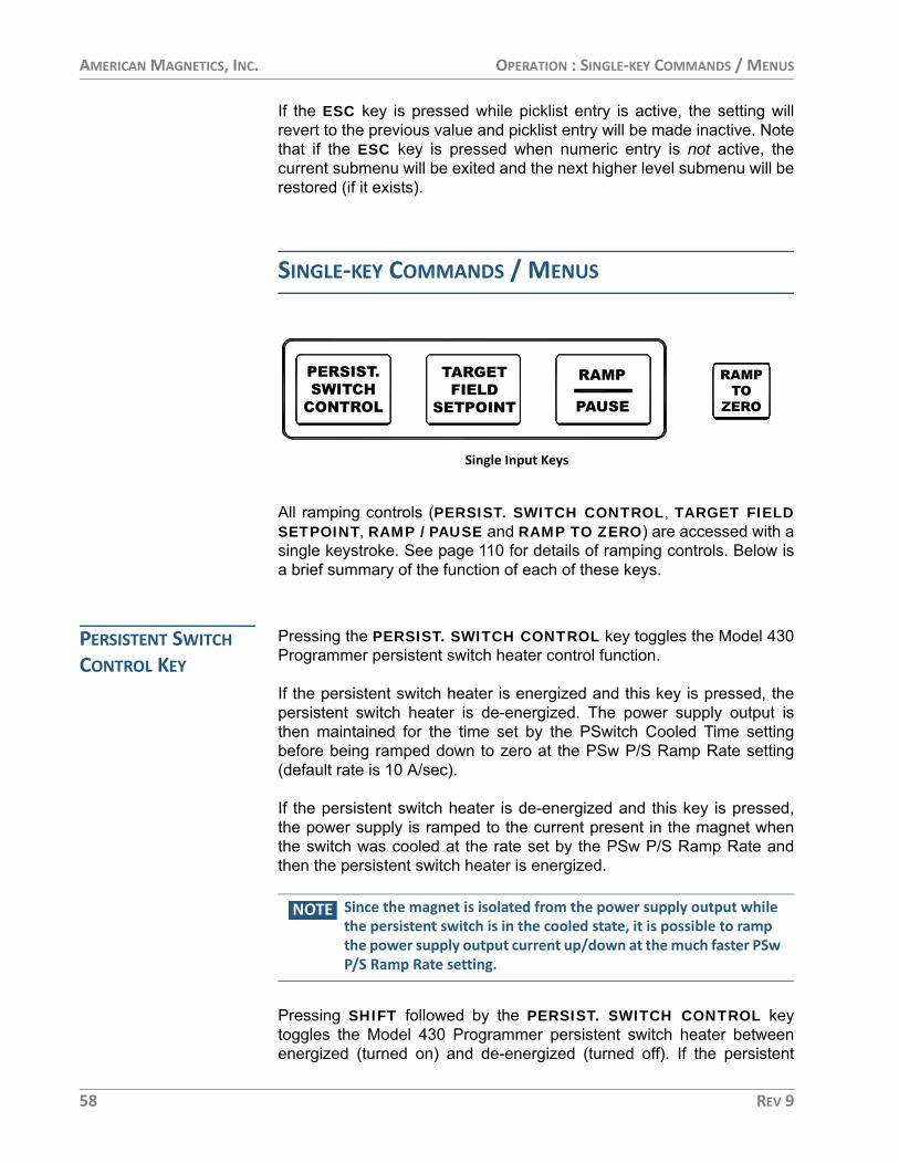
AMERICAN MAGNETICS, INC. OPERATION : SINGLE-KEY COMMANDS / MENUS
If the ESC key is pressed while picklist entry is active, the setting willrevert to the previous value and picklist entry will be made inactive. Notethat if the ESC key is pressed when numeric entry is not active, thecurrent submenu will be exited and the next higher level submenu will berestored (if it exists).
SINGLE-KEY COMMANDS / MENUS
All ramping controls (PERSIST. SWITCH CONTROL, TARGET FIELDSETPOINT, RAMP / PAUSE and RAMP TO ZERO) are accessed with asingle keystroke. See page 110 for details of ramping controls. Below isa brief summary of the function of each of these keys.
PERSISTENT SWITCH CONTROL KEY
Pressing the PERSIST. SWITCH CONTROL key toggles the Model 430Programmer persistent switch heater control function.
If the persistent switch heater is energized and this key is pressed, thepersistent switch heater is de-energized. The power supply output isthen maintained for the time set by the PSwitch Cooled Time settingbefore being ramped down to zero at the PSw P/S Ramp Rate setting(default rate is 10 A/sec).
If the persistent switch heater is de-energized and this key is pressed,the power supply is ramped to the current present in the magnet whenthe switch was cooled at the rate set by the PSw P/S Ramp Rate andthen the persistent switch heater is energized.
NOTE Since the magnet is isolated from the power supply output while the persistent switch is in the cooled state, it is possible to ramp the power supply output current up/down at the much faster PSw P/S Ramp Rate setting.
Pressing SHIFT followed by the PERSIST. SWITCH CONTROL keytoggles the Model 430 Programmer persistent switch heater betweenenergized (turned on) and de-energized (turned off). If the persistent
Single Input Keys
PAUSE
RAMPTARGETFIELD
SETPOINT
RAMPTO
ZERO
PERSIST.SWITCH
CONTROL
58 REV 9

AMERICAN MAGNETICS, INC. OPERATION : SINGLE-KEY COMMANDS / MENUS
switch heater is energized and this key is pressed, the persistent switchheater is de-energized. If the persistent switch heater is de-energizedand this key is pressed, the persistent switch heater is energized.
NOTE The power supply output current remains unchanged when SHIFT + PERSIST. SWITCH CONTROL is used. Only the state of the persistent switch heater is changed.
When the persistent switch heater is energized, the Model 430Programmer is supplying current to the appropriate pins (9 & 10) of theMagnet Station Connectors in order to drive the persistent switch into anormal state, which takes the magnet out of persistent mode. Magnetpersistent mode is indicated by the MAGNET IN PERSISTENT MODELED4.
The Model 430 Programmer will beep once (indicating an error) if theuser attempts to activate the switch heater control without first indicatinga persistent switch is installed in the Switch submenu and specifying theswitch heating current, switch transition detect method, and the heatedtime and cooled time5 for timer-based transitions.
The nominal switch heating current is listed on the magnet specificationsheet, and may be entered in the Model 430 Programmer by accessingthe Switch submenu6. In addition to the heating current, the user mustalso specify the switch transition detection method, PSw P/S Ramp Rateand cooling gain. If the switch transition is timer-based, then the heatedtime and cooled time must also be specified.
TIMER-BASED SWITCH TRANSITIONS
The heated time allows the Model 430 Programmer to delaycompensating the internal control logic until the magnet isguaranteed to be in the circuit. The heated time can be set from aminimum of 5 seconds to a maximum of 120 seconds within theLoad submenu7. The default heating period of 20 seconds isadequate for the majority of persistent switches. If the magnetappears unstable just after the switch heating period expires,increase the switch heated time to allow for complete heating.
The cooled time allows the persistent switch sufficient time to becooled to superconducting state before the current is changed inthe magnet. The cooled time can be set from a minimum of 5seconds to a maximum of 3600 seconds within the Loadsubmenu8. The default cooling period of 20 seconds is adequate
4. See page 70.5. See page 83 and page 85.6. See page 85.7. See page 86.
REV 9 59

AMERICAN MAGNETICS, INC. OPERATION : SINGLE-KEY COMMANDS / MENUS
for the majority of wet persistent switches. Conduction-cooledswitches may require longer times to transition from resistive tosuperconducting state and can benefit from direct magnetvoltage-based transition detection as described below.
During timer countdowns, the remaining time in seconds isdisplayed in the default display status area. A value of (0)indicates the respective timer has expired.
MAGNET VOLTAGE-BASED SWITCH TRANSITIONS
For magnet voltage-based switch detections, a running averageand variance of the magnet voltage is calculated. If the runningaverage is less than 0.5 mV and the variance is less than anadjustable preset limit (typically 10 nV2), the switch is consideredin the cooled state. The variance must exceed four times (4x) thepreset limit to be considered as exiting the cooled state.
The average and variance limits essentially describe a constantmagnet voltage of zero (0) volts given the internal Model 430resolution of the voltage measurement, which is the expectedvalue a cooled persistent switch should exhibit. An additionalsafety factor delay of 5 seconds is added for each transition oncethe limits are exceeded.
Magnet voltage-based transition detection requires magnetvoltage taps connected to pins 11 & 12 of the Magnet Stationconnector as described on page 194.9
During magnet voltage-based transitions, the running variance innanovolts2 (nV squared) is shown in the default display statusarea. A continuous value of (0) indicates a cooled switch state.
The default cooling gain of 0.0% may be adequate for the majority of wetpersistent switches. However, this setting may result in some magnetdrift during persistent switch cooling, especially with conduction cooledswitches. Increasing the cooling gain adds control loop gain during theswitch cooling cycle. Too little may result in magnet drift during switchcooling. Too much may result in power supply instability during switchcooling, which could potentially prevent the switch from cooling. Mostsystems requiring some cooling gain to control magnet drift will likelywork with value set to 25%.
8. See page 86.9. The additional provision of connecting the magnet voltage taps to Auxiliary Input 1 must be
addressed if using a Model 430 with firmware prior to version 3.00. See page 202.
60 REV 9

AMERICAN MAGNETICS, INC. OPERATION : SINGLE-KEY COMMANDS / MENUS
NOTE During the period the switch is being heated or cooled, the Model 430 Programmer will not allow ramping functions to be executed, and will beep once and indicate an error if the user attempts to initiate a ramping operation.
Refer to page 113 for a complete description of magnet persistent switchcontrol.
TARGET FIELD SETPOINT KEY
Pressing the TARGET FIELD SETPOINT key provides a menu forsetting the target field/current. The target field/current is the field orcurrent to which the Model 430 Programmer ramps the superconductingmagnet when it is not paused. The target field/current may be set equalto or less than the Current Limit10 or equivalent field (per defined coilconstant).
The target field/current requires a sign for four-quadrant systems since itdefines a single setpoint within the entire field/current range of thesystem (positive and negative).
When on the default display, pressing the SHIFT + TARGET FIELDSETPOINT keys will display the Magnet Current/Field for three secondsbefore reverting to the default display. Pressing any key will clear thedisplay. The value displayed is as follows:
• When in driven mode, the present current/field will be displayed.• When in persistent mode, the current/field displayed is the value that was
circulating in the magnet at the time persistent switch was cooled.
RAMP / PAUSE KEY Pressing the RAMP / PAUSE key toggles the Model 430 Programmerbetween the ramping mode and the paused mode. If the RAMP / PAUSEkey is pressed while the Model 430 is ramping, the ramping is paused. Ifthe RAMP / PAUSE key is pressed while the Model 430 is paused, theModel 430 continues ramping.
10. See page 88.
+50.00 A - Target Field (kG)+0.50 Vs +50.000
+0.25 A P Magnet Current (A) 0.00 Vs +10.00 A
REV 9 61

AMERICAN MAGNETICS, INC. OPERATION : SHIFT+KEY COMMANDS / MENUS
RAMP TO ZERO KEY Pressing the RAMP TO ZERO key causes the Model 430 Programmerto immediately begin ramping field/current up or down to zero field/current at the defined ramp rate(s). Ramping to zero may be interruptedat any time by pressing the RAMP / PAUSE key, which causes theModel 430 Programmer to enter the PAUSED mode and maintain thefield/current present at the point it was paused.
NOTE If the RAMP TO ZERO function is paused and then the RAMP / PAUSE button is pressed a second time, the Model 430 Programmer will begin ramping to the target field, not to zero. If it is desired to ramp to zero after the RAMP / PAUSE button is pressed, press the RAMP TO ZERO button again to continue ramping to zero from the paused state.
NOTE If the magnet is persistent (i.e. switch heater is not energized) when the RAMP TO ZERO key is pressed, the Model 430 Programmer ramps the power supply current to zero; the magnet current will remain constant since the magnet is in persistent mode.
SHIFT+KEY COMMANDS / MENUS
The most commonly used commands and menus (other than rampingcontrols) are accessed using the SHIFT key followed by a numerickeypad key. Use of the specific SHIFT+key commands and menus isdescribed in sections specific to the functionality of that specificSHIFT+key combination.
SHIFT+Key Functions
SHIFT 1 2 3
4 5
7 8
. +/-0
9
6
RAMPRATE
INCR.FIELD
FIELDUNITS
Vs <> Vm VOLTMETER
FINEADJUST
P. SWITCHHTR. CUR. STAB.
DECR.FIELD
FIELD <>CURRENT
VOLTAGELIMIT
RESETQUENCH
62 REV 9

AMERICAN MAGNETICS, INC. OPERATION : SHIFT+KEY COMMANDS / MENUS
In general, a SHIFT+key command is executed or a menu is accessedby first pressing the SHIFT key (which turns on the SHIFT LED), andthen pressing11 one of the keys of the numeric keypad (0 through 9, “.”,or “+/-”). The SHIFT+key command / menu for each key of the numerickeypad is shown in light blue text at the top of each key.
To access the voltage limit menu, for example, press the SHIFT key, andthen press the VOLTAGE LIMIT key (also the 2 key). Note that some ofthe SHIFT+key menus can also be accessed using the setup menu.
Pressing the ESC key or the SHIFT key a second time will clear theSHIFT function and return the keypad to it's numeric function.
RAMP RATE (SHIFT+1) Use of the RAMP RATE (SHIFT+1) key provides a menu for settingramp rate(s). The ramp rate may be set12 within the range specified forthe specific Model 430 Programmer configuration (refer to thespecifications on page 7). If field units are being used, then the ramp ratesetting is displayed and set in units of kG/sec or T/sec).
The allowable range is defined by the setting of the coil constant and theallowable range of the ramp rate in terms of current as specified in thetable on page 7. If the Ramp Segments value13 is greater than 1, thenthe menu also allows setting of the field or current range for each ramprate segment.
The Model 430 Programmer will ramp at the specified rate if theavailable compliance of the power supply is sufficient and the VoltageLimit is not exceeded. The Model 430 automatically decreases the ramprate internally during operation if either the available compliance of thepower supply is insufficient, or the Voltage Limit is active.
RAMP RATE EXAMPLE
An example (using a magnet with rated current of 60 A14) willillustrate the use of the ramp rate menus. The example assumesthat the field/current units have been set to amperes and theramp segments value has been set to three (3) segments. Theramping is chosen with rates as follows:
1. ±0.2 A/s from 0 to ±55 A
2. ±0.1 A/s from ±55 to ±58 A
3. ±0.05 A/s above ±58 A.
11. Note the SHIFT key plus the following key-press are sequential, not simultaneous.12. Using numerical keys as described on page 54 or the fine adjust knob (page 55).13. See page 95.14. In this example, the Current Limit is set at the rated magnet current of 60 A.
REV 9 63

AMERICAN MAGNETICS, INC. OPERATION : SHIFT+KEY COMMANDS / MENUS
In the following discussion, the fine adjust knob15 can optionallybe used for ramp rate adjustment if the persistent switch isheated (or if no persistent switch is installed). If the user attemptsto edit ramp rate segments using the fine adjust knob while aninstalled switch is cooled, the Model 430 Programmer willproduce one beep to indicate an error16. Similarly, if the switch isheated (or no switch is installed), attempting to use the fineadjust knob for PSw P/S ramp rate will produce one beep17.
Pressing SHIFT and then RAMP RATE will access the ramp ratemenu. The numeric and ENTER keys (or the fine adjust knob)are used to set the segment #1 ramp rate to a value of 0.2 A/sec.
The right arrow key is pressed once to access the segment #1range display. The numeric and ENTER keys (or fine adjustknob) are used to set the segment #1 current range upper boundto a value of 55 A.
Pressing the right arrow key accesses the next (second)segment ramp-rate display. The segment #2 ramp rate is set to avalue of 0.1 A/sec.
The right arrow key is pressed once to access the segment #2range display. The segment #2 current range upper bound is setto a value of 58 A.
15. See page 55.16. Since the PSw P/S ramp rate is active in that scenario, and not the segmented ramp rate.17. Since the standard segmented ramp rate is active in that scenario, and not the PSw P/S ramp
rate.
+50.00 A - Seg.1 Ramp Rate (A/sec)+0.50 Vs ±0.2000
+50.00 A - Seg.1 Range (A)+0.50 Vs 0.0 to ±55.0
+50.00 A - Seg.2 Ramp Rate (A/sec)+0.50 Vs ±0.1000
+50.00 A - Seg.2 Range (A)+0.50 Vs ±55.0 to ±58.0
64 REV 9

AMERICAN MAGNETICS, INC. OPERATION : SHIFT+KEY COMMANDS / MENUS
Pressing the right arrow key accesses the next (third) segmentramp rate display. The segment #3 ramp rate is set to a value of0.05 A/sec.
Pressing the right arrow key accesses the segment #3 currentrange display.
NOTE If there is more than one segment, the upper bound of the last segment is always the Current Limit18 and it will be displayed as “±Limit” as shown below and cannot be edited.
Now, when current is in the range of 0 to ±55 A, ramping will becontrolled at ±0.2 A/sec. When current is in the range of ±55 to±58 A, ramping will be controlled at ±0.1 A/sec and when currentis greater than ±58 A (up to the limit of 60 A), ramping will becontrolled at ±0.05 A/sec.
If ramp rate of a ramp segment is being edited while the Model430 is ramping and the system current/field transitions from thecurrently edited segment to the next before the adjustment hasbeen committed with the ENTER key, the adjusted value will bediscarded. The display will update to show the new segmentramp rate, and the fine adjust knob will apply to the new segment(assuming the ENTER key is pressed before the segment hascompleted).
If at some later time it is desired to set the Current Limit to avalue less than 58 A, only the first two ramp segments wouldremain active since the new “limit” falls within the range ofsegment #2. The display for segment 2 range would then appearas follows19.
18. Refer to page 88.19. If the Current Limit were to be set below 55 A, only segment #1 would be active, and would
display the upper bound of “±Limit”.
+50.00 A - Seg.3 Ramp Rate (A/sec)+0.50 Vs ±0.0500
+50.00 A - Seg.3 Range (A)+0.50 Vs ±58.0 to ±Limit
+50.00 A - Seg.2 Range (A)+0.50 Vs ±55.0 to ±Limit
REV 9 65

AMERICAN MAGNETICS, INC. OPERATION : SHIFT+KEY COMMANDS / MENUS
Any unused segment(s) above the Current Limit will remain inmemory (retaining their original parameters) until one or morebecome active again when the Current Limit is raised into orabove the respective ranges. When displayed, the higher-rangeunused segments will show a range of “±Limit to ±Limit” until re-activated20.
VOLTAGE LIMIT (SHIFT+2)
Use of the VOLTAGE LIMIT (SHIFT+2) key provides a menu for settingthe limit for output voltage for the power supply the Model 430Programmer controls. This value should be set to a high enough valueso that under normal conditions, the Voltage Limit is never reached. Thevalue can be set by using either the numeric keypad entry as describedpage 54 or the fine adjust knob (on page 55).
Note that the voltage drop in the leads must be accounted for whensetting the Voltage Limit, as well as the voltage drop of an energyabsorber if in use (see page 110 for details of how to determine theappropriate Voltage Limit).
The Voltage Limit may be set less than or equal to the maximum outputvoltage of the power supply.21 The Voltage Limit functions as a bipolarlimit.
If Voltage Limit becomes active while ramping, it will be indicated by areverse illumination character “V” for the status indicator.
Once the Voltage Limit function becomes active, the current, andtherefore field, will no longer be ramping linearly with time as the voltageavailable to charge the magnet will be reduced as the total loop voltage
20. Also if the number of segments is increased, the new segments are added to the upper end of the ramp range, and default to the ramp rate of the previous segment with the range of ±Limit to ±Limit until set up.
+50.00 A - Seg.3 Range (A)+0.50 Vs ±Limit to ±Limit
21. Refer to the table on page 75.
+50.00 A - Voltage Limit (V)+0.50 Vs ±2.000
+40.92 A Mode: Ramping+2.50 Vs V PSwitch Heater: ON
66 REV 9

AMERICAN MAGNETICS, INC. OPERATION : SHIFT+KEY COMMANDS / MENUS
will be limited. As the i x R drop of the leads increases with current, thevoltage available to charge the magnet will be reduced.
RESET QUENCH (SHIFT+3)
The RESET QUENCH (SHIFT+3) key is used whenever a quenchdetection has occurred and is being indicated on the display (exampleshown below).
When a quench detection has occurred, the Model 430 Programmer willrespond to no further input until the RESET QUENCH key is pressed, oruntil the quench condition is cleared by a remote command. For morediscussion of quench detection see page 123.
INCREMENT FIELD (SHIFT+4)
The INCR. FIELD (SHIFT+4) key is used to manually increase the field.This is done at the defined ramp rate(s).
When the INCR. FIELD key is pressed, the current/field begins rampingup. If the INCR. FIELD key is pressed again (while the current/field ismanually ramping up), the ramping will be paused. Alternately, theRAMP / PAUSE key may be pressed to pause manual ramping. Manualramping will continue until paused or the Current Limit22 is achieved.
NOTE If the current/field is negative, using the INCR. FIELD key to increase (make more positive) the current/field, the magnitude of the current/field decreases.
FIELD <> CURRENT (SHIFT+5)
The FIELD <> CURRENT (SHIFT+5) key is used to toggle between theuse of field units, either kG (kilogauss) or T (tesla), and the use of currentunits (A)23. If the Model 430 Programmer is using field units (either kG orT) and the FIELD <> CURRENT SHIFT-key is pressed, the Model 430Programmer will begin using current units (A). Conversely, if the Model430 is using current units (A) and the FIELD <> CURRENT SHIFT-keyis pressed, the Model 430 will begin using field units (either kG or T).
0.00 A - Quench Detect @ +45.81 A 0.00 Vs PSwitch Heater: ON
22. See page 88.23. The value is always displayed in current (A) when an installed persistent switch is in the
cooled state since the value represents power supply current only, independent of the stored (i.e. persistent) magnet current/field.
REV 9 67

AMERICAN MAGNETICS, INC. OPERATION : SHIFT+KEY COMMANDS / MENUS
NOTE The Model 430 Programmer cannot use field units unless a valid coil constant has been entered24.
DECREMENT FIELD (SHIFT+6)
The DECR. FIELD (SHIFT+6) key is used to manually decrease thecurrent/field. This is done at the defined ramp rate(s).
When the DECR. FIELD key is pressed, the current/field begins rampingdown. If the DECR. FIELD key is pressed again (while the current/field ismanually ramping down), the ramping will be paused. Alternately, theRAMP / PAUSE key may be pressed to pause manual ramping. Manualramping will continue until paused or the Current Limit25 is achieved.
NOTE If the current/field is negative, using the DECR. FIELD key to decrease (make less positive) the current/field, the magnitude of the current/field increases.
FIELD UNITS (SHIFT+7) Use of the FIELD UNITS (SHIFT+7) key provides a shortcut to thepicklist menu26 for defining whether the field is specified and displayed inunits of kilogauss (kG) or tesla (T). The selected option also applies toremote interface commands. The default setting is kilogauss.
PERSISTENT SWITCH HEATER CURRENT (SHIFT+8)
Use of the P. SWITCH HTR. CUR. (SHIFT+8) key provides a shortcut tothe menu27 for setting persistent switch heater current. The value can beset to between 0.0 and 125.0 mA. The default value is 10.0 mA unlesspreset by AMI to match a specific superconducting magnet.
24. See page 81.25. See page 88.26. See page 96.
+50.00 A - Field Units+0.50 Vs Kilogauss Tesla
27. See page 85.
+50.00 A — PSwitch Current (mA)+0.50 Vs 10.0
68 REV 9

AMERICAN MAGNETICS, INC. OPERATION : SHIFT+KEY COMMANDS / MENUS
STABILITY (SHIFT+9) Use of the STAB. (SHIFT+9) key provides a shortcut to the menu fordefining the Model 430 stability setting. The stability setting is specifiedin percent and controls the transient response and stability of thesystem. The valid input range is from 0.0 to 100.0%. The default value is0.0% unless preset by AMI to match a specific superconducting magnet.
See page 79 for details of how to determine the stability setting to use.
VS <> VM (SHIFT+0) The Vs <> Vm (SHIFT+0) key is used to toggle the voltage displaybetween display of the voltage across the magnet (Vm) and the powersupply output voltage (Vs). See page 52 for details.
VOLT METER (SHIFT+.) The VOLT METER (SHIFT+.) key is used to toggle the main displaybetween display of a voltmeter indicating magnet voltage (Vm) or supplyvoltage (Vs), and display of ramp mode and persistent switch heaterstate. See page 53 for details.
FINE ADJUST (SHIFT +/-) The FINE ADJUST (SHIFT +/-) key is used to enable the use of thefront panel fine adjust knob to adjust numeric values. See page 55 fordetails.
SHIFT + PERSIST. SWITCH CONTROL
This keystroke enables persistent switch control without some automaticsequencing features. Refer to page 58.
REV 9 69

AMERICAN MAGNETICS, INC. OPERATION : LED INDICATORS
LED INDICATORS
The Model 430 Programmer has six front panel LED indicators. See thefront panel illustration and table on page 4 for the location of theseindicators.
POWER-ON INDICATOR The green power-on LED indicates that the Model 430 Programmer ispowered on.
MAGNET STATUS INDICATORS
Four LEDs are grouped together to show the magnet status.
FIELD AT TARGET INDICATOR
The green FIELD AT TARGET LED indicates that the current isat the target value. If the magnet is not in persistent mode(persistent switch heater is on), then this is an indication that themagnet field has reached the target value. If the magnet isalready in persistent mode, then this is an indication that thecurrent being supplied to the magnet system has reached thetarget value.
MAGNET IN PERSISTENT MODE INDICATOR
CAUTION If the Model 430 Programmer power is turned off while the persistent switch is heated, persistent switch heating will be lost and the magnet will enter persistent mode. The Model 430 will not have a record of that event. Therefore the MAGNET IN PERSISTENT MODE LED state will be incorrect (remain OFF) when the Model 430 Programmer power is restored.
Magnet Status LED Indicators
FIELD AT TARGETMAGNET IN PERSISTENT MODE
MAGNET QUENCHCURRENT LEADS ENERGIZED
70 REV 9

AMERICAN MAGNETICS, INC. OPERATION : LED INDICATORS : SHIFT INDICATOR
CAUTION If the Model 430 Programmer power supply system is powered off and moved from one magnet system to another, the MAGNET IN PERSISTENT MODE LED may not correctly indicate the state of the magnet system until the first time the persistent switch heater is turned off.
NOTE Should the magnet quench while the magnet is in persistent mode and the Model 430 Programmer is off, the persistent mode indicator LED will be incorrect when the Model 430 Programmer is turned on again.
The green MAGNET IN PERSISTENT MODE LED indicatesthat the persistent switch heater is off, and that when it wasturned off, the magnet had greater than 0.1% of the maximumsystem current28 flowing through it. The state of this LED is keptin nonvolatile memory when the Model 430 is powered off, sothat the LED state is retained even during a power cycle of theModel 430. Thus, the MAGNET IN PERSISTENT MODE LED isan indicator that the magnet is persistent and has at least somepersistent field.
CURRENT LEADS ENERGIZED INDICATOR
The blue CURRENT LEADS ENERGIZED LED indicates that atleast 0.1% of the maximum system current29 is flowing in theModel 430 power supply system output current leads.
MAGNET QUENCH INDICATOR
The red MAGNET QUENCH LED indicates that a magnetquench condition has been detected. See page 123 for details.
SHIFT INDICATOR The green SHIFT LED indicates that the SHIFT key has been pressed,and the next numeric keypad key pressed will actuate the shiftedfunction (shown in light blue text on the key label) rather than thenumeric keypad function. See page 62 for details of SHIFT key use.
28. Example: For a system with an Imax value of 125 A, 0.1% of the current would be 0.125 A.29. Example: For a system with an Imax value of 250 A, 0.1% of the current would be 0.250 A.
REV 9 71

AMERICAN MAGNETICS, INC. OPERATION : SETUP MENU : MENU NAVIGATION
SETUP MENU
Setup of the Model 430 Programmer requires the user to navigate thesetup menu. Navigation of the setup menu is intuitive — quite similar, forexample, to the use of a cell phone menu.
ENTERING / EXITING SETUP MENU
To enter the setup menu, simply press the MENU key. When in any ofthe setup menus, pressing the MENU key will exit the setup menu. TheMENU key toggles the Model 430 Programmer in and out of setupmode. Alternately, if the top level setup menu is being displayed,pressing the ESC key exits the setup menu.
MENU NAVIGATION Pressing the MENU key enters the menu structure at the top level. Thedisplay will look approximately as shown below:
The item selector ( ) points to whichever submenu was last used. Theleft and right arrows at the ends of the displayed submenu selectionsindicate that there are other submenu selections off screen, to the leftand/or right of the submenu selections shown.
The left and right keypad arrows (to the left and right of the MENU key)move the item selector between the different submenu items. Pressingthe left keypad arrow moves the item selector one item to the left andpressing the right keypad arrow moves the item selector one item to theright. When the last item is reached, and the right keypad arrow ispressed, the item selector will move to the first item. Likewise, when theitem selector is pointing to the first item, and the left keypad arrow ispressed, the item selector will move to the last item.
Pressing the ENTER key opens the submenu to which the item selectoris pointing when the ENTER key is pressed. See page 73 throughpage 106 for detailed descriptions of each submenu.
Pressing the ESC key exits a submenu and moves the next higher levelsubmenu if it exists. If the top level setup menu is being displayed,pressing the ESC key exits the setup menu.
0.00 A - Setup Mode (Select one)+0.50 Vs Supply Load Misc
72 REV 9
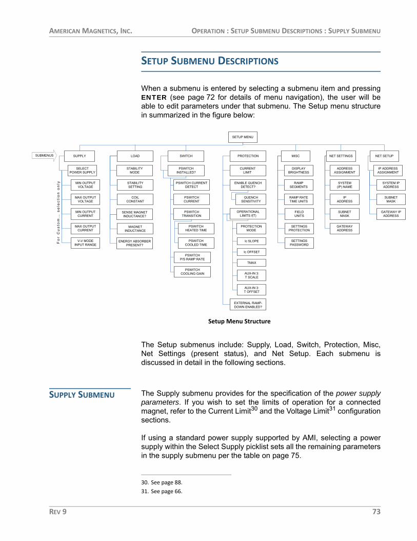
AMERICAN MAGNETICS, INC. OPERATION : SETUP SUBMENU DESCRIPTIONS : SUPPLY SUBMENU
TUPSUBM
RESSNMENT
TEM IPDRESS
BNETASK
EWAY IPDRESS
SETUP SUBMENU DESCRIPTIONS
When a submenu is entered by selecting a submenu item and pressingENTER (see page 72 for details of menu navigation), the user will beable to edit parameters under that submenu. The Setup menu structurein summarized in the figure below:
The Setup submenus include: Supply, Load, Switch, Protection, Misc,Net Settings (present status), and Net Setup. Each submenu isdiscussed in detail in the following sections.
SUPPLY SUBMENU The Supply submenu provides for the specification of the power supplyparameters. If you wish to set the limits of operation for a connectedmagnet, refer to the Current Limit30 and the Voltage Limit31 configurationsections.
If using a standard power supply supported by AMI, selecting a powersupply within the Select Supply picklist sets all the remaining parametersin the supply submenu per the table on page 75.
MISC
NET SETTINGS
LOAD
NET SE
SUPPLY
SELECTPOWER SUPPLY
MIN OUTPUTVOLTAGE
MAX OUTPUTVOLTAGE
MIN OUTPUTCURRENT
MAX OUTPUTCURRENT
V-V MODEINPUT RANGE
ENUS
Fo
r Custom…
se
lec
tio
n o
nly STABILITY
SETTING
COILCONSTANT
MAGNETINDUCTANCE
PSWITCHINSTALLED?
PSWITCH CURRENTDETECT
PSWITCHCURRENT
PSWITCHHEATED TIME
ENERGY ABSORBERPRESENT?
DISPLAYBRIGHTNESS
RAMPSEGMENTS
RAMP RATETIME UNITS
FIELDUNITS
QUENCHSENSITIVITY
SETTINGSPROTECTION
SETTINGSPASSWORD
ADDRESSASSIGNMENT
SYSTEM(IP) NAME
IPADDRESS
SUBNETMASK
GATEWAYADDRESS
IP ADDASSIG
SYSAD
SUM
GATAD
PSWITCHCOOLED TIME
PSWITCHP/S RAMP RATE
CURRENTLIMIT
PSWITCHCOOLING GAIN
SWITCH
PROTECTION
ENABLE QUENCHDETECT?
EXTERNAL RAMP-DOWN ENABLED?
STABILITYMODE
SENSE MAGNETINDUCTANCE?
PROTECTIONMODE
OPERATIONALLIMITS f(T)
Ic SLOPE
Ic OFFSET
TMAX
AUX-IN 3:T SCALE
AUX-IN 3:T OFFSET
SETUP MENU
PSWITCHTRANSITION
Setup Menu Structure
30. See page 88.31. See page 66.
REV 9 73

AMERICAN MAGNETICS, INC. OPERATION : SETUP SUBMENU DESCRIPTIONS : SUPPLY SUBMENU
NOTE The Supply submenu is unique in that it has only the Select Supply picklist as a sublevel (unless Custom is chosen from the picklist of Select Supply options). For this reason, picklist entry is active as soon as the Supply submenu is selected; it is not necessary to first press ENTER to make picklist entry active in the Select Supply picklist. Also, pressing ESC while within the Select Supply picklist not only makes picklist entry inactive and sets the picklist selection back to where it was when the Supply submenu was selected; it also exits the Select Supply picklist.
SELECT SUPPLY PICKLIST
The Select Supply picklist provides a set of picklist items thatcontain presets for standard AMI power supplies. The left andright keypad arrows are used to cycle through the list ofselections.
When the item selector points at the desired power supply in thepicklist, ENTER is pressed to select that power supply; all powersupply parameters are set when the power supply model isselected. Pressing ESC while viewing the Select Supply picklistleaves the power supply selection where it was when the Supplysubmenu was selected, and exits the Select Supply picklist. Theavailable Select Supply picklist values and associated powersupply parameters are provided in the table on the followingpage.
0.00 A — Select Supply*+0.50 Vs AMI 4Q06125PS
74 REV 9

AMERICAN MAGNETICS, INC. OPERATION : SETUP SUBMENU DESCRIPTIONS : SUPPLY SUBMENU
NOTE The current must be less than 0.1% of Imax in order to change the Select Supply picklist value. If a change is attempted with current above this value, the Model 430 Programmer will beep and ignore the keypress. Power supply selection should also preferably be performed with the power supply off for maximum safety.
Select Supply picklist values and associated parameters.
Power SupplyMin OutputVoltage (V)
Max OutputVoltage (V)
Min OutputCurrent (A)
Max OutputCurrent (A)
V-V Mode InputRange (V)
AMI 08150PS 0 +8.000 0 +150.000 0 to +10.000
AMI 12100PS0 +12.000 0
+100.0000 to +10.000
AMI 12200PS +200.000
AMI 4Q05100PS −5.000 +5.000 −100.000 +100.000
−10.000 to +10.000AMI 4Q06125PS
-6.000 +6.000-125.000 +125.000
AMI 4Q06250PS -250.000 +250.000
AMI 4Q12125PS -12.000 +12.000 -125.000 +125.000
AMI 10100PS
0
+10.000
0
+100.0000 to +5.000
AMI 10200PS +200.000
AMI 05120PS
+10.000a
+100.000
0 to +10.000
AMI 05240PS +200.000
AMI 05360PS +300.000
AMI 05600PS +500.000
AMI 03300PS +8.000 +300.000
HP 6260B
−10.000 +10.000
0.000 +100.000
Kepco BOP 20-5Mb −5.000 +5.000−10.000 to +10.000
Kepco BOP 20-10Mb −10.000 +10.000
Xantrex XFR 7.5-140 0 +7.500 0 +140.000 0 to +10.000
Custom...c −20.000 +20.000 −200.000 +200.000 −10.000 to +10.000
a. The individual 05100PS power supply unit will source +10.000 VDC at up to 120 A. However, the standard configuration of this series of power supplies includes the Model 601 Energy Absorber to provide bipolar operation. The 05xx0-430-601 series of power supply systems provides a maximum available voltage to the load of ±5.000 VDC at multiples of 120 or 150 A, up to 600 A depending on the system selected.
b. The Kepco BOP power supplies are used in the 4Q1005PS-430 and 4Q1010PS-430 systems are limited to only one-half the output voltage range since the supplies are designed to safely dissipate only one-half the rated power output.
c. The values shown for the Custom... option are defaults. The user should enter the appropriate values within the respective submenus. Custom values, once entered, are saved in nonvolatile memory.
REV 9 75

AMERICAN MAGNETICS, INC. OPERATION : SETUP SUBMENU DESCRIPTIONS : SUPPLY SUBMENU
The power supply settings define the output voltage and currentranges for a specific power supply. For example, V-I diagramsare presented in the diagram below for the AMI 12100PS andAMI 4Q06125PS selections.
The AMI 12100PS operates as a one-quadrant system withoutthe addition of an energy absorber. As shown at left in thediagram, with the addition of an AMI Model 601 energy absorber,the AMI 12100PS system can also function as a two-quadrantsupply providing +7V to -5V at the power supply system outputterminals.
The AMI 4Q06125PS power supply operates as a four-quadrantpower supply without the addition of an energy absorber asshown at right in the diagram below.
The addition of an energy absorber to the system does notchange the capabilities of the power supply itself (or the valuesentered for the supply). The addition of an energy absorber does,however, change the system operating ranges.
CUSTOM... PICKLIST ITEM
Custom... is a unique Select Supply picklist item. When selected,it opens a deeper submenu in which the custom power supplyparameters (Min Output Voltage, Max Output Voltage, MinOutput Current, Max Output Current and V-V Mode Input Range)are entered. Entry of each of these parameters is describedbelow.
+20
-20
+200-200
+20
-20
+200-200
VoltageVoltage
Current Current
AMI 12100PSOPERATING RANGE
AMI 12100PS + MODEL 601 ENERGY ABSORBEROPERATING RANGE
AMI 4Q06125PSOPERATING RANGE5V
Example Power Supply Outputs
76 REV 9

AMERICAN MAGNETICS, INC. OPERATION : SETUP SUBMENU DESCRIPTIONS : SUPPLY SUBMENU
MIN OUTPUT VOLTAGE
The minimum output voltage is specified in volts (V) and reflectsthe minimum output voltage compliance of a connected powersupply. The valid range is 0.000 to -20.000 V, and can be set byusing either the numeric keypad as described on page 54 or thefine adjust knob (on page 55). A unipolar power supply has aminimum output voltage of 0.000 V.
MAX OUTPUT VOLTAGE
The maximum output voltage is specified in volts (V) and reflectsthe maximum output voltage compliance of a connected powersupply. The valid range is +0.001 to +20.000 V, and can be set byusing either the numeric keypad as described on page 54 or thefine adjust knob (on page 55).
MIN OUTPUT CURRENT
The minimum output current is specified in amperes (A) andreflects the minimum output current capacity of a connectedpower supply. The valid range is 0.000 to -100,000 A32, and canbe set by using either the numeric keypad as described onpage 54 or the fine adjust knob (on page 55). A unipolar powersupply has a minimum output current of 0.000 A.
MAX OUTPUT CURRENT
The maximum output current is specified in amperes (A) andreflects the maximum output current capacity of a connected
32. The minimum and maximum output currents are also bounded by the Model 430 Program-mer configuration (refer to specifications on page 7 and in the Appendix). The entered value cannot exceed the input current measurement hardware limits.
0.00 A — Min Output Voltage (V) 0.00 Vs -6.000
0.00 A — Max Output Voltage (V) 0.00 Vs +6.000
0.00 A — Min Output Current (A) 0.00 Vs +0.000
0.00 A — Max Output Current (A) 0.00 Vs +100.000
REV 9 77

AMERICAN MAGNETICS, INC. OPERATION : SETUP SUBMENU DESCRIPTIONS : LOAD SUBMENU
power supply. The valid range is 0.001 to +100,000 A1, and canbe set by using either the numeric keypad as described onpage 54 or the fine adjust knob (on page 55).
V-V MODE INPUT RANGE
The voltage-to-voltage mode input range defines the remoteprogramming voltage input range required by the connectedpower supply. The remote programming voltage is the outputsignal provided by the Model 430 Programmer as an input to theconnected power supply.
This submenu item provides a picklist of six preset selectionsand does not allow numeric entry of a range. The picklist valuesare shown in the table below.
LOAD SUBMENU When the Load submenu is selected, several parameters associatedwith the superconducting magnet load can be viewed and/or changed.
STABILITY MODE
The stability mode provides configuration of the loop control gainfor operating with a magnet or testing a system on a short-circuitload. The three available selections are Auto, Manual, and Test.
The Auto stability mode automatically sets the control gain basedon the configured presence or absence of a persistent switch,and the entered or measured magnet inductance value asdescribed on page 82. A reasonably accurate guess (e.g. within25%) or measurement must be provided for the Auto mode tofunction correctly.
V-V Mode Input Range Picklist Selections
+0.000 to -5.000 +0.000 to +8.000
+0.000 to +5.000 -5.000 to +5.000
+0.000 to +10.000 -10.000 to +10.000
0.00 A — V-V Mode Input Range (V) 0.00 Vs -10.000 to +10.000
0.00 A — Stability Mode+0.50 Vs Auto Manual Test
78 REV 9

AMERICAN MAGNETICS, INC. OPERATION : SETUP SUBMENU DESCRIPTIONS : LOAD SUBMENU
The Manual stability mode provides complete control over thecontrol gain based on a numerical entry for the stability setting.The Manual mode requires the operator to enter a stability settingper the description on page 79.
The Test stability mode is designed to allow the user to test thefunction of the system with the power leads to the magnetshorted together at the magnet connection point. This allowsramping of the system to verify proper setup. The Test modeshould only be used with shorted magnet power leads forcheckout purposes.
NOTE It is important that the full length of the power leads to the magnet be connected during the Test mode since the leads provide some resistive load (albeit in the milliohm range) for the power supply. The output current of a truly shorted supply output (i.e. zero resistance load) is very difficult to control in voltage mode and may be unstable.
STABILITY SETTING
The stability setting is specified in percent and controls thetransient response and stability of the system. The value can beset by using either the numeric keypad as described on page 54or the fine adjust knob (on page 55). The valid range is from 0.0to 100.0%. The default value is 0.0% unless preset by AMI tomatch a specific superconducting magnet.
STABILITY SETTING FOR MAGNETS WITHOUT A PERSISTENT SWITCH33
Superconducting magnets without a persistent switch34 require aspecific Model 430 Programmer stability setting based on themagnet inductance as follows:
For magnet inductance ≤ 100 Henries (H):Stability Setting = (100 - H)
For magnet inductance > 100 Henries:Stability Setting = 0
33. For maximum Vm stability, you may opt to use a stabilizing resistor instead. See page 43 for details. For stabilizing resistor configurations, use the Stability Setting plot specified in the next section for magnets with a persistent switch.
34. Effective with Model 430 firmware version 1.62 or later, magnets without a switch may be operated without a stabilizing resistor present using the Stability Settings specified.
0.00 A — Stability Setting (%)+0.50 Vs 0.0
REV 9 79

AMERICAN MAGNETICS, INC. OPERATION : SETUP SUBMENU DESCRIPTIONS : LOAD SUBMENU
STABILITY SETTING FOR MAGNETS WITH A PERSISTENT SWITCH
The graph below may be used as a guide to set the stabilitysetting for magnets with a persistent switch installed andinductance of less than 3 henries. Magnets with an inductance ofgreater than 3 henries that have a persistent switch installedshould operate with a stability setting of 0.0%.
The Model 430 Programmer internal control loop gain isproportional to the multiplier (100% – [Stability Setting]). For thisreason, small changes in stability setting have a large effect onstability as the value approaches 100%. Changing the stabilitysetting from 99.9% to 99.8% changes the gain multiplier from0.1% to 0.2% (changing the gain multiplier by a factor of 2, a100% increase in the gain multiplier). Note, however, that thesame 0.1% change in Stability Setting from 90% to 89.9% onlychanges the gain multiplier from 10% to 10.1% (changing thegain multiplier by a factor of 1.01, a 1% change in gain multiplier).
What this means is that if the stability setting is being adjusted toexperimentally determine its optimum setting (using the graphabove as a starting point) the recommended incremental
Model 420 Stability Setting vs. Magnet Inductance
0
10
20
30
40
50
60
70
80
90
100
0 1 2 3 4 5 6 7
Inductance (H)
Stab
ility
Set
ting
(%)
Stability Setting vs. Magnet (with PSwitch) Inductance
Model 430 Stability Setting vs. Magnet Inductance(for Magnets with Persistent Switch)
80 REV 9

AMERICAN MAGNETICS, INC. OPERATION : SETUP SUBMENU DESCRIPTIONS : LOAD SUBMENU
changes for various stability setting ranges are shown in thefollowing table.
NOTE The Model 430 will not operate in a stable fashion on a short-circuit load unless it is configured for Test stability mode (see page 78). Otherwise the 430 control logic assumes an inductive superconducting magnet load is connected to the circuit.
COIL CONSTANT
The coil constant is a scaling factor which converts the current tokilogauss (kG) or tesla (T). It is also often referred to as the field-to-current ratio. The coil constant is specified in kilogauss/ampere or tesla/ampere. The value can be set by using either thenumeric keypad as described on page 54 or the fine adjust knob(on page 55).
Values from 0.001 to 999.99999 are acceptable for the coilconstant. The default value is 1.00000 kG/A (or 0.10000 T/A)unless preset by AMI to match a specific superconductingmagnet. If the coil constant value is 0.0 kG/A (or 0.0 T/A), then noconversion from amperes to kilogauss or tesla is performed — alloperations will be performed and displayed in terms of amperes.
If the coil constant is not explicitly stated within asuperconducting magnet’s specifications, the value can beobtained by dividing the rated field by the rated current. Note that1 T = 10 kG.
Maximum Recommended Stability Setting Changes
Stability Setting RangeMaximum Recommended Stability Setting Change
98% to 100% 0.1%
94% to 98% 0.2%
84% to 94% 0.5%
44% to 84% 2%
0% to 44% 5%
0.00 A — Coil Constant (kG/A)+0.50 Vs 0.90000
REV 9 81

AMERICAN MAGNETICS, INC. OPERATION : SETUP SUBMENU DESCRIPTIONS : LOAD SUBMENU
SENSE MAGNET INDUCTANCE
This menu pick will start a process to measure the inductance ofthe load magnet. The inductance is determined by measuring thevoltage developed across the magnet (Vm) with a fixed di/dt(current rate-of-change in A/sec) passed through the load. Thefunction must be executed with the magnet ramping.35 When thesense is initiated by pressing the ENTER key, the algorithm willwait for 2 seconds to allow the charge rate to stabilize and thenmake voltage and current measurements, calculate theinductance, and display the result.
The sensed magnet inductance is automatically saved as thepresent magnet inductance and is immediately used to adjust thecontrol gains if the Model 430 is configured for Auto stabilitymode (see page 78).
If the magnet is persistent, not ramping, or encounters a ramprate change during the measurement, the measurement will beaborted with a displayed error notification, and any existingmagnet inductance value is retained.
MAGNET INDUCTANCE
The magnet inductance submenu displays the presentinductance value for the magnet load and allows manual entry ofa new value or initial guess (an initial guess within ~25% isadequate). The magnet inductance value is saved betweenpower cycles.
The magnet inductance value, when entered, is immediatelyused for control gain configuration if the Model 430 is set for Autostability mode (see page 78).
35. See page 111.
0.00 A — Sense Magnet Inductance? 0.00 Vs Calculate (start w/ENTER)
+46.19 A Sense Magnet Inductance?+0.50 Vs 32.13 H
0.00 A — Magnet Inductance (H)+0.50 Vs 32.13
82 REV 9

AMERICAN MAGNETICS, INC. OPERATION : SETUP SUBMENU DESCRIPTIONS : SWITCH SUBMENU
NOTE If connecting a different magnet load, please ensure that the magnet inductance is set with a known value or an initial guess in order to ensure proper operation.
ENERGY ABSORBER PRESENT
This picklist value indicates whether an energy absorber, such asthe AMI Model 601, is connected to the power supply system.The default setting is NO.
It is important for this setting to be correct since the control gaintables of the Model 430 Programmer compensate for theadditional load of the energy absorber if present. The increasedgain when an energy absorber is present will also decrease (butnot eliminate) the time required for the system to “forward bias”the energy absorber.36
SWITCH SUBMENU The Switch submenu provides a top menu for indicating if apersistent switch is installed on the presently connected magnetload, and, if so, several submenus for configuring the variousoperating parameters for the switch.
PSWITCH INSTALLED
This picklist value indicates whether or not a persistent switch isinstalled.
If YES is selected, the PSwitch Current Detect, PSwitch Current,PSwitch Transition, PSwitch Heated Time, PSwitch Cooled Time,PSw P/S Ramp Rate, and PSwitch Cooling Gain settings aremade available within the Switch submenu.
36. The Model 430 Programmer will bring the output voltage of the power supply to the point where the energy absorber can provide current to the magnet.
+50.00 A — Energy Absorber Present?+0.50 Vs NO YES
0.00 A — PSwitch Installed? 0.00 Vm NO YES
REV 9 83

AMERICAN MAGNETICS, INC. OPERATION : SETUP SUBMENU DESCRIPTIONS : SWITCH SUBMENU
If NO is selected, the various settings are not made availablewithin the Switch submenu and the PERSIST. SWITCHCONTROL key becomes inoperable.
The default value is YES unless preset by AMI to match aspecific superconducting magnet.
PSWITCH CURRENT DETECT (MA)
This function will automatically determine the proper value ofheater current in a persistent switch installed on a magnetconnected to the power supply system. The power supply shouldbe energized and at zero current. When the ENTER key ispressed to initiate the process, the following steps occur:
1. The persistent switch current is set to 0.1 mA.
2. The power supply current is ramped to 2 A at 0.1 A/sec.
3. After the power supply current reaches 2 A, the persistent switch cur-rent is slowly increased (as shown on the display) until the Model 430 Programmer detects a change in the load, indicative of the persistent switch transitioning from superconducting to resistive. Before this transition is detected, the display will show the heater current value as it is increased in the persistent switch heater; the magnet current is changed back to zero during this process.
4. The current that was present when the superconducting to resistive transition occurred is displayed.
NOTE If the PSwitch Current determined by this method is accepted as described below, the detection process will exit to the heated switch mode with zero amps being delivered to the magnet.
5. If the ENTER key is pressed, the determined value of PSw current is stored in the Model 430 Programmer. If the escape key is pressed,
0.00 A P PSwitch Current Detect(mA) 0.00 Vm Auto detect
+2.00 A P PSwitch Current Detect(mA)+0.37 Vm Detecting...(26.7mA)
0.00 A P PSwitch Current Detect(mA) 0.00 Vm 27.2
84 REV 9

AMERICAN MAGNETICS, INC. OPERATION : SETUP SUBMENU DESCRIPTIONS : SWITCH SUBMENU
the value determined in step 4 above is discarded and the previously set persistent switch current is retained.
PSWITCH CURRENT
The persistent switch heater current can be manually set to anyvalue between 0.0 and 125.0 mA. The value can be set by usingeither the numeric keypad as described on page 54 or the fineadjust knob (on page 55). The default value is 10.0 mA unlesspreset by AMI to match a specific superconducting magnet.
PSWITCH TRANSITION
The persistent switch transition (from heated-to-cooled and vice-versa) can be detected by one of two methods: timer-based or bydirect sensing of the magnet voltage.
The timer-based method is the default and simply uses heatedand cooled state timers as entered by the operator in the PSwitchHeated Time and PSwitch Cooled Time settings.
Optionally, the operator can choose to use the magnet voltagemethod. This method works by directly sensing the running meanand variance of the magnet voltage and comparing them topreset limits. This method has the advantage of typicallyrequiring much less time to sense the transition of the persistentswitch from the heated to cooled state.
NOTE In order to use the magnet voltage switch transition detection, higher resolution of the magnet voltage measurement is necessary. This is achieved by connecting the magnet voltage to Auxiliary Input 1, which has a ±1.0 VDC input range with 20 times more resolution (~0.5 mV/bit) than the standard magnet voltage input.
Model 430 units that ship with version 3.00 or later firmwareinstalled have internally connected the magnet voltage input fromthe Magnet Station connector to the Auxiliary Input 1 (therefore,the Auxiliary Input 1 is consumed and is not available for generaluse). For older, already fielded units the user will be required to
+50.00 A — PSwitch Current (mA)+0.50 Vs 10.0
+50.00 A — PSwitch Transition+0.50 Vs Timer Magnet Voltage
REV 9 85

AMERICAN MAGNETICS, INC. OPERATION : SETUP SUBMENU DESCRIPTIONS : SWITCH SUBMENU
install an external jumper cable from one of the Magnet Stationconnectors to the Auxiliary Input 1 to use the magnet voltagebased switch transition feature. See page 202 for more details.
NOTE The magnet voltage method of sensing persistent switch transitions requires the magnet voltage input to the rear panel Magnet Station connector as described on page 193. Please note that some magnet system manufacturers do not provide magnet voltage taps.
PSWITCH HEATED TIME
The persistent switch heated time is only displayed for, andapplies only to, the timer-based switch transition method and isthe amount of time required for the persistent switch to heatcompletely and become fully normal (resistive). The time may beset to any value between 5 and 120 seconds37. The value can beset by using either the numeric keypad as described on page 54or the fine adjust knob (on page 55). The default is 20 secondsunless preset by AMI to match a specific superconductingmagnet.
During the persistent switch heating period, the Model 430Programmer ramping functions are disabled. The time delay isnecessary to ensure that the Model 430 will not switch to thehigher control gain required for proper magnet operation beforethe magnet is actually available in the circuit (not being shuntedby the persistent switch). If magnet operation is not stable afterexpiration of the heating period, increase the heated time to allowmore time for the switch to heat. The default value of 20 secondsis adequate for the majority of wet and dry persistent switches.
PSWITCH COOLED TIME
The PSwitch Cooled Time is only displayed for, and applies onlyto, the timer-based switch transition method and is the amount of
37. During the heating cycle, a “countdown” will be displayed indicating the number of seconds remaining in the cycle.
+50.00 A — PSwitch Heated Time (sec)+0.50 Vs 20
+50.00 A — PSwitch Cooled Time (sec)+0.50 Vs 20
86 REV 9

AMERICAN MAGNETICS, INC. OPERATION : SETUP SUBMENU DESCRIPTIONS : SWITCH SUBMENU
time required for the persistent switch to cool completely andbecome fully superconducting. The time may be set to any valuebetween 5 and 3600 seconds38. The value can be set by usingeither the numeric keypad as described on page 54 or the fineadjust knob (on page 55). The default is 20 seconds unlesspreset by AMI to match a specific superconducting magnet.
During the persistent switch cooling period, the Model 430Programmer ramping functions are disabled. The default value of20 seconds is adequate for many wet persistent switches.Persistent switches on conduction cooled magnets (dry switches)will require significantly longer cooling times than wet switches.
For dry switches, the operator may want to consider the optionalmagnet voltage switch transition detection method if magnetvoltage taps are available and connected to the Model 430Programmer.
PSWITCH POWER SUPPLY RAMP RATE
The persistent switch power supply ramp rate is the rate at whichthe magnet power supply will automatically be ramped up ordown while an installed persistent switch is in the cooled state.The rate may be set to any value between 0.1 and 10 A/sec.
The purpose of this parameter is to reduce the amount of timethe system requires to either match an existing persistent magnetcurrent, or to reach zero current for powering off a system withthe magnet in a persistent state. This ramp rate can be set muchhigher than the rate required while charging/discharging themagnet (note that a persistent magnet is not in-circuit). In fact,the typical practice is to set this parameter to its maximum value.
The value can be set by using either the numeric keypad asdescribed on page 54 or the fine adjust knob (on page 55). Thedefault is 10 A/sec unless preset by AMI to match a specificsuperconducting magnet system.
38. During the cooling cycle, a “countdown” will be displayed indicating the number of seconds remaining in the cycle.
+50.00 A — PSw P/S Ramp Rate (A/sec)+0.50 Vs 10
REV 9 87
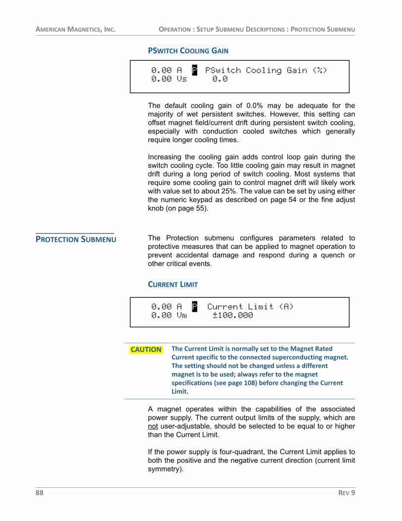
AMERICAN MAGNETICS, INC. OPERATION : SETUP SUBMENU DESCRIPTIONS : PROTECTION SUBMENU
PSWITCH COOLING GAIN
The default cooling gain of 0.0% may be adequate for themajority of wet persistent switches. However, this setting canoffset magnet field/current drift during persistent switch cooling,especially with conduction cooled switches which generallyrequire longer cooling times.
Increasing the cooling gain adds control loop gain during theswitch cooling cycle. Too little cooling gain may result in magnetdrift during a long period of switch cooling. Most systems thatrequire some cooling gain to control magnet drift will likely workwith value set to about 25%. The value can be set by using eitherthe numeric keypad as described on page 54 or the fine adjustknob (on page 55).
PROTECTION SUBMENU The Protection submenu configures parameters related toprotective measures that can be applied to magnet operation toprevent accidental damage and respond during a quench orother critical events.
CURRENT LIMIT
CAUTION The Current Limit is normally set to the Magnet Rated Current specific to the connected superconducting magnet. The setting should not be changed unless a different magnet is to be used; always refer to the magnet specifications (see page 108) before changing the Current Limit.
A magnet operates within the capabilities of the associatedpower supply. The current output limits of the supply, which arenot user-adjustable, should be selected to be equal to or higherthan the Current Limit.
If the power supply is four-quadrant, the Current Limit applies toboth the positive and the negative current direction (current limitsymmetry).
0.00 A P PSwitch Cooling Gain (%) 0.00 Vs 0.0
0.00 A P Current Limit (A) 0.00 Vm ±100.000
88 REV 9

AMERICAN MAGNETICS, INC. OPERATION : SETUP SUBMENU DESCRIPTIONS : PROTECTION SUBMENU
The Current Limit is normally preset by AMI to match a specifiedsuperconducting magnet. If AMI is not supplying the magnet of ifthe specific magnet data has not been provided by the customer,the Model 430 will ship with the Current Limit set at the defaultvalue of ±80 A. The figure on the following page shows thedefault Current Limit (±80 A) and a Voltage Limit (±2.5 V) as asub-range within the 4Q06125PS power supply output limits.
The Current Limit can be set by using either the numeric keypadas describe on page 54 or the fine adjust knob (on page 55). TheModel 430 Programmer will beep once, indicate an error, anddeny the change if the user attempts to set the Current Limitbelow the present Target Field Setpoint or above the maximumoutput current of the selected power supply.
ENABLE QUENCH DETECT
The internal quench detection function of the Model 430Programmer may be enabled or disabled according to thepreference of the user. The default value is NO.
A user input for external quench detection is also provided on therear panel of the Model 430 Programmer39. The external input
Current and Voltage Limits set within the Supply Ranges
V
A
80 -80
± CURRENT LIMIT (A)
±2.5
± VOLTAGE LIMIT (V)
AMI 4Q06125PS AVAILABLE RANGE
OPERATING RANGE asLIMITED by CURRENT LIMIT
+10
-10
+200-200
+50.00 A — Enable Quench Detect?+0.50 Vs NO YES
REV 9 89

AMERICAN MAGNETICS, INC. OPERATION : SETUP SUBMENU DESCRIPTIONS : PROTECTION SUBMENU
overrides the internal quench detection function of the Model 430and cannot be disabled. For further discussion of the quenchdetection logic and operation, please refer to on page 123.
ADDITIONAL QUENCH DETECTION SELECTIONS
If the optional Operational Limits f(T) functionality is enabled (seepage 91), then the quench detection menu includes someadditional selections as illustrated below:
As described previously, the quench detect can be set to Off andis inactive. If set to Current, the detection is based on magnetcurrent only which is the same as the base quench detectionfunctionality as described above.
If set to Tmax, the detection logic will only be based on the inputtemperature from an external measurement device that isconnected to Auxiliary Input 3 on the rear panel of the Model 430(see page 202).
If set to Both, the quench detection logic will operate on both themagnet current and the temperature measurement provided viaAuxiliary Input 3. If either violates the predefined detection logic,a quench will be detected.
QUENCH SENSITIVITY
This picklist value specifies the sensitivity (formerly called “rate”)of the quench detection algorithm. The default “Normal” value willbe appropriate for most magnets. Occasionally, some magnetsquench very slowly and the value of this parameter may need tobe adjusted to a more sensitive value so that the Model 430Programmer detects the gradual, slow quench.
The available range for this parameter is five (5) steps from leastto most sensitivity. If the magnet quenches and the Model 430Programmer does not detect the quench, the sensitivity should
39. Refer to page 200.
+50.00 A — Enable Quench Detect?+0.50 Vs Off Current Tmax Both
+50.00 A P Quench Sensitivity (Rate)+0.50 Vs Less < Normal > More
90 REV 9

AMERICAN MAGNETICS, INC. OPERATION : SETUP SUBMENU DESCRIPTIONS : PROTECTION SUBMENU
be increased (i.e. More sensitivity) until all quenches aredetected.
OPERATIONAL LIMITS40
This heads a menu subsection containing various constantsassociated with protection based on a linear relationship for amaximum allowable current, termed as Ic, given a temperaturemeasured via the Auxiliary Input 3 (see page 202). Press theENTER key to access the associated submenu parameters.
The equations that relate the parameters in this subsection aredefined as:
where Ic is in Amperes, IcSlope is Amperes/Kelvin, T is theAuxiliary Input channel 3 temperature in Kelvin, IcOffset is inAmperes, and Tmax is in Kelvin. The Ic limit is applied in a bipolarfashion, i.e. it is applied to the magnet current magnitude.
The equations above define an operating region that is illustratedin the “Ic vs. Tempeature” plot at the top of the following page,with example parameter values of -22 A/K for IcSlope, 180 A forIcOffset, and 5.5 K for Tmax. The valid operational region isalong and to the left of the line.
PROTECTION MODE
This setting controls how the maximum current protection isapplied. If the Protection Mode setting is Off, then no additionalprotection is applied.41
40. The Operational Limits menu can be hidden with an internal hardware switch. If this menu is not visible, then the hardware switch has been set to hide it. Contact an Authorized AMI Technical Support Representative if you wish to enable this feature.
41. The Tmax parameter may still be used as part of the quench detection logic, see page 123.
+50.00 A — Operational Limits f(T)+0.50 Vs Edit Constants
If T Tmax≤ Ic IcSlope( )T IcOffset( )+=
If T Tmax> Ic 0=
+50.00 A — Protection Mode+0.50 Vs Off On Entry Cont f(T)
REV 9 91

AMERICAN MAGNETICS, INC. OPERATION : SETUP SUBMENU DESCRIPTIONS : PROTECTION SUBMENU
If the Protection Mode setting is On Entry, the Target FieldSetpoint is checked only during a new entry against the presentlycalculated value of Ic and the new entry must be less than orequal to Ic. The Model 430 Programmer will beep once, indicatean error, and deny the new entry to the Target Field/CurrentSetpoint if the value exceeds Ic.
If the Protection Mode setting is Cont f(T), representing thecontinuous function of temperature, the Target Field Setpointentry protection is applied and the operating current of themagnet is continuously checked against the calculated value ofIc based on the present temperature measured via the AuxiliaryInput channel 3. This mode actively limits the magnet current toless than or equal to Ic.
If the temperature increases during operation and the presentmagnet current then exceeds Ic, the magnet is automaticallyramped down in current magnitude to satisfy the Ic limit at thespecified system ramp rate (this includes ramping the magnet tozero field/current if the present temperature exceeds Tmax). Ifattempting to ramp the magnet current above Ic, the magnetcurrent is held at the value of Ic. Either limited condition isindicated by an inverse video T character in the status indicatordisplay which indicates the “Temperature Limited” state.
If the Protection Mode is “Off”, the present temperaturemeasured via Auxiliary Input channel 3 can be displayed in thedefault display by pressing the right or left arrow keys. If theProtection Mode is “On Entry” or “Cont f(T)” both the real-timecalculated value of Ic and the current temperature are displayed.
0.00
20.00
40.00
60.00
80.00
100.00
120.00
140.00
160.00
180.00
200.00
0.00 1.00 2.00 3.00 4.00 5.00 6.00 7.00 8.00 9.00 10.00
Ic (A
)
Temperature (K)
Ic vs. Temperature
Example of Ic (i.e. critical current) vs. Temperature protection line
92 REV 9

AMERICAN MAGNETICS, INC. OPERATION : SETUP SUBMENU DESCRIPTIONS : PROTECTION SUBMENU
Ic is always displayed in Amperes. This default display option isillustrated below along with an illustration of the status indicatorindicating a temperature-limited condition (i.e. the reverse-videoT character):
To remove the Ic and/or temperature display, simply press the leftor right arrow key again.
IC SLOPE
This value sets the Ic Slope parameter in Amperes/Kelvin. Notethat for superconducting magnets, the slope value will benegative since the maximum current density increases withdecreasing temperature.
IC OFFSET
This value sets the Ic Offset parameter in Amperes. This valueshifts the entire Ic line by a current offset. A higher offset valuewill increase the value of Ic for a given temperature.
TMAX
This value is a maximum allowable system temperature asmeasured via the Auxiliary Input channel 3 in Kelvin. The Model430 Programmer will limit entry of the Target Field/CurrentSetpoint to a value of zero if the present temperature exceedsTmax. If the Protection Mode is set for “Cont f(T)”, then the
+50.53 A T Mode: Ramping: Ic=50.54.50 K No PSwitch Installed
Illustration of optional default display showing the value of Ic, the present Aux-In 3 temperature, and a temperature-limited condition.
+50.00 A — Ic Slope (A/K)+0.50 Vs -22.000
+50.00 A — Ic Offset (A)+0.50 Vs +150.000
+50.00 A — Tmax (K)4.50 K 6.000
REV 9 93

AMERICAN MAGNETICS, INC. OPERATION : SETUP SUBMENU DESCRIPTIONS : PROTECTION SUBMENU
magnet will also be ramped to zero field/current if thetemperature exceeds Tmax.
AUX-IN 3: T SCALE
This value controls the scaling of the voltage measured via theAuxiliary Input channel 3 (see page 202). The measured voltageis multipled by this scale factor in Kelvin/Volts. The value isdetermined by the specific output scaling applied by the externaltemperature measurement device.
NOTE The correctness of this scaling parameter is critical to the accurate operation of the protection afforded by the Operational Limits function.
AUX-IN 3: T OFFSET
This value controls the offset in Kelvin of the temperaturemeasured via the Auxiliary Input channel 3 (see page 202). Themeasured voltage is first multipled by the T Scale factor and thenthe T Offset is added to determine the voltage-to-temperatureconversion. The value is determined by the specific output offsetapplied by the external temperature measurement device.
NOTE The correctness of this offset parameter is critical to the accurate operation of the protection afforded by the Operational Limits function.
ENABLE EXTERNAL RAMPDOWN
The External Rampdown function of the Model 430 Programmercan be used to allow an external contact-signal to cause themagnet to be ramped to zero field (even if it is in persistentmode) should a fault or alarm occur in a magnet system. Signals
+50.00 A — Aux-In 3: T Scale (K/V)4.50 K +1.000
+50.00 A — Aux-In 3: T Offset (K)4.50 K 0.000
0.00 A — External Rampdown Enabled? 0.00 Vs NO YES
94 REV 9
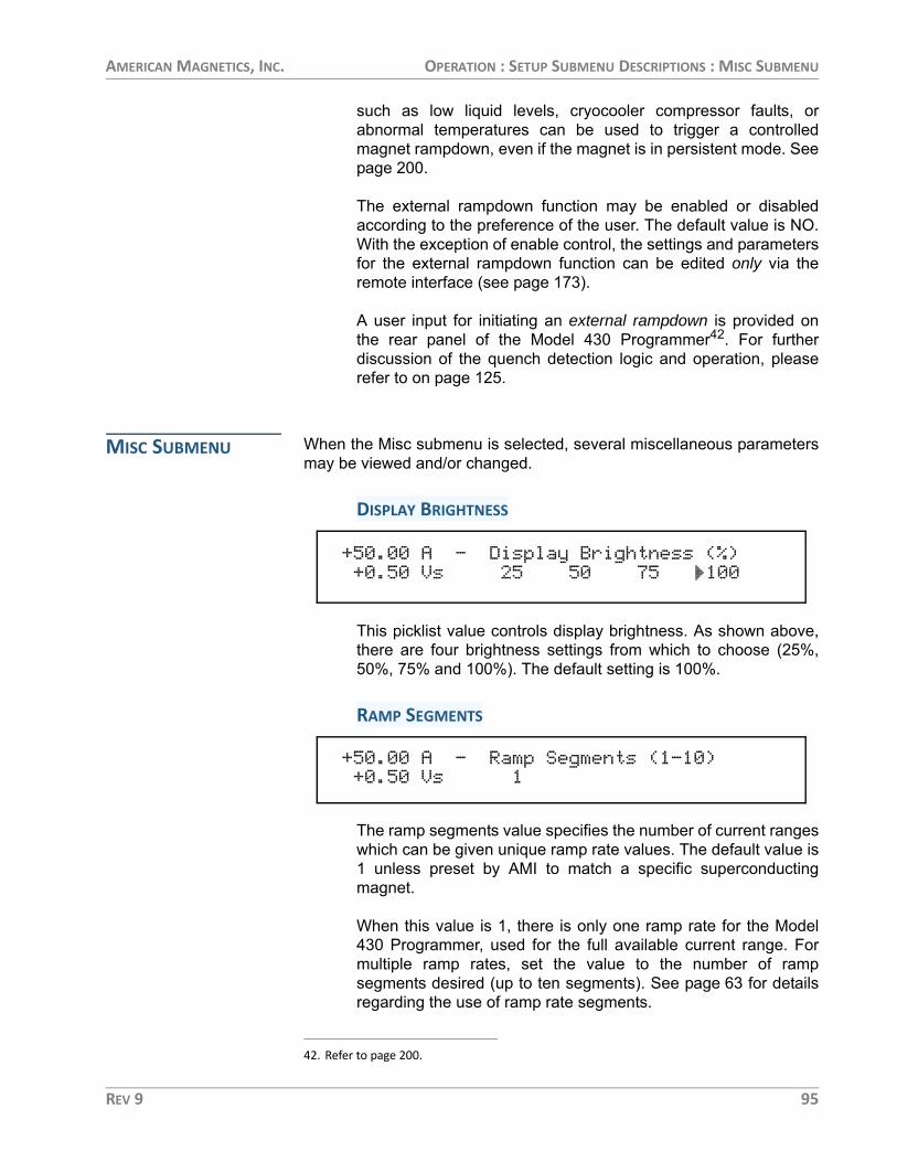
AMERICAN MAGNETICS, INC. OPERATION : SETUP SUBMENU DESCRIPTIONS : MISC SUBMENU
such as low liquid levels, cryocooler compressor faults, orabnormal temperatures can be used to trigger a controlledmagnet rampdown, even if the magnet is in persistent mode. Seepage 200.
The external rampdown function may be enabled or disabledaccording to the preference of the user. The default value is NO.With the exception of enable control, the settings and parametersfor the external rampdown function can be edited only via theremote interface (see page 173).
A user input for initiating an external rampdown is provided onthe rear panel of the Model 430 Programmer42. For furtherdiscussion of the quench detection logic and operation, pleaserefer to on page 125.
MISC SUBMENU When the Misc submenu is selected, several miscellaneous parametersmay be viewed and/or changed.
DISPLAY BRIGHTNESS
This picklist value controls display brightness. As shown above,there are four brightness settings from which to choose (25%,50%, 75% and 100%). The default setting is 100%.
RAMP SEGMENTS
The ramp segments value specifies the number of current rangeswhich can be given unique ramp rate values. The default value is1 unless preset by AMI to match a specific superconductingmagnet.
When this value is 1, there is only one ramp rate for the Model430 Programmer, used for the full available current range. Formultiple ramp rates, set the value to the number of rampsegments desired (up to ten segments). See page 63 for detailsregarding the use of ramp rate segments.
42. Refer to page 200.
+50.00 A — Display Brightness (%)+0.50 Vs 25 50 75 100
+50.00 A — Ramp Segments (1-10)+0.50 Vs 1
REV 9 95

AMERICAN MAGNETICS, INC. OPERATION : SETUP SUBMENU DESCRIPTIONS : MISC SUBMENU
RAMP RATE TIME UNITS
This picklist value specifies the unit of time used to enter and thedisplay ramp rate. If Seconds is selected, ramp rate is entered inA/s, kG/s or T/s; if Minutes is selected, ramp rate is entered in A/min, kG/min or T/min. The selected unit value also applies toremote interface commands. The default setting is Seconds.
FIELD UNITS
This picklist value specifies whether the field is specified anddisplayed in units of kilogauss (kG) or tesla (T). The unitsselected also applies to remote interface commands. The defaultsetting is kilogauss.
SETTINGS PROTECTION
Settings Protection allows virtually43 every command and menu/submenu setting to be protected from alteration or use. If asetting is locked, it cannot be used from the front panel withoutfirst unlocking the setting, which requires entering the correctpassword. Note that settings protection only applies to frontpanel access, and not to remote access (via Ethernet or RS-232).
The use of settings protection allows specific commands and/orsettings to be locked by a magnet system “administrator,” so thatthe general user cannot execute those commands and/or modifythose settings. The implementation of settings protection in theModel 430 Programmer is very flexible; it allows as many or asfew commands and/or settings to be locked as the magnetsystem administrator desires. The magnet system administratormay lock all but a few commands/settings, so that, for instance,
43. The one exception is the RAMP TO ZERO button which cannot be locked. Also, Magnet Inductance and Net Settings are not subject to locking due to their “read-only” nature.
+50.00 A — Ramp Rate Time Units+0.50 Vs Seconds Minutes
+50.00 A — Field Units+0.50 Vs Kilogauss Tesla
+50.00 A — Settings Protection+0.50 Vs Edit Settings
96 REV 9

AMERICAN MAGNETICS, INC. OPERATION : SETUP SUBMENU DESCRIPTIONS : MISC SUBMENU
the general user has access to only the RAMP / PAUSE andRAMP TO ZERO keys. Conversely, the administrator may lock,for instance, only the Current Limit setting from use by thegeneral user.
If an attempt is made to use a locked command or setting, theModel 430 Programmer beeps twice; the command is notaccepted and the setting is not altered.
When ENTER is pressed to change settings protection, thepassword must be correctly entered before settings protectioncan be edited.
Using the keypad, type the numeric password (up to 4-digits) andpress ENTER. The default password is 1234. If an incorrectpassword is entered, the Model 430 Programmer beeps andagain prompts for the password. Once the password has beencorrectly entered, the protection value (Locked or Unlocked) canbe edited for each setting. The default protection value for allsettings is Unlocked.
NOTE Once the password has been correctly entered, if no keys are pressed for one minute, the Settings Protection submenu will be exited, and the password must be entered again if further changes to settings protection are desired.
If the correct password has been forgotten, contact AMITechnical Support for assistance. To change the password, seepage 103.
PSWITCH CONTROL LOCK
This picklist value specifies whether use of the PERSIST.SWITCH CONTROL key is locked or unlocked. The defaultvalue is Unlocked.
+50.00 A — Enter Password*+0.50 Vs _
+50.00 A — PSwitch Control Lock+0.50 Vs Locked Unlocked
REV 9 97

AMERICAN MAGNETICS, INC. OPERATION : SETUP SUBMENU DESCRIPTIONS : MISC SUBMENU
TARGET FIELD SETPT LOCK
This picklist value specifies whether use of the TARGET FIELDSETPOINT key is locked or unlocked. The default value isUnlocked.
RAMP / PAUSE LOCK
This picklist value specifies whether use of the RAMP / PAUSEkey is locked or unlocked. The default value is Unlocked.
RAMP TO ZERO LOCK
This picklist value specifies whether use of the RAMP TO ZEROkey is locked or unlocked. The default value is Unlocked.
RAMP RATE SETTINGS LOCK
This picklist value specifies whether ramp rate settings arelocked or unlocked. Ramp rate settings protected by this settingare: use of the RAMP RATE key menu, editing of the RampSegments value (under the Misc submenu) and editing of theRamp Time Units value (under the Misc submenu). The defaultvalue is Unlocked.
POWER SUPPLY LOCK
This picklist value specifies whether the Select Supply picklistvalue is locked or unlocked. If the Select Supply value is
+50.00 A — Target Field Setpt Lock+0.50 Vs Locked Unlocked
+50.00 A — Ramp / Pause Lock+0.50 Vs Locked Unlocked
+50.00 A — Ramp To Zero Lock+0.50 Vs Locked Unlocked
+50.00 A — Ramp Rate Settings Lock+0.50 Vs Locked Unlocked
+50.00 A — Power Supply Lock+0.50 Vs Locked Unlocked
98 REV 9
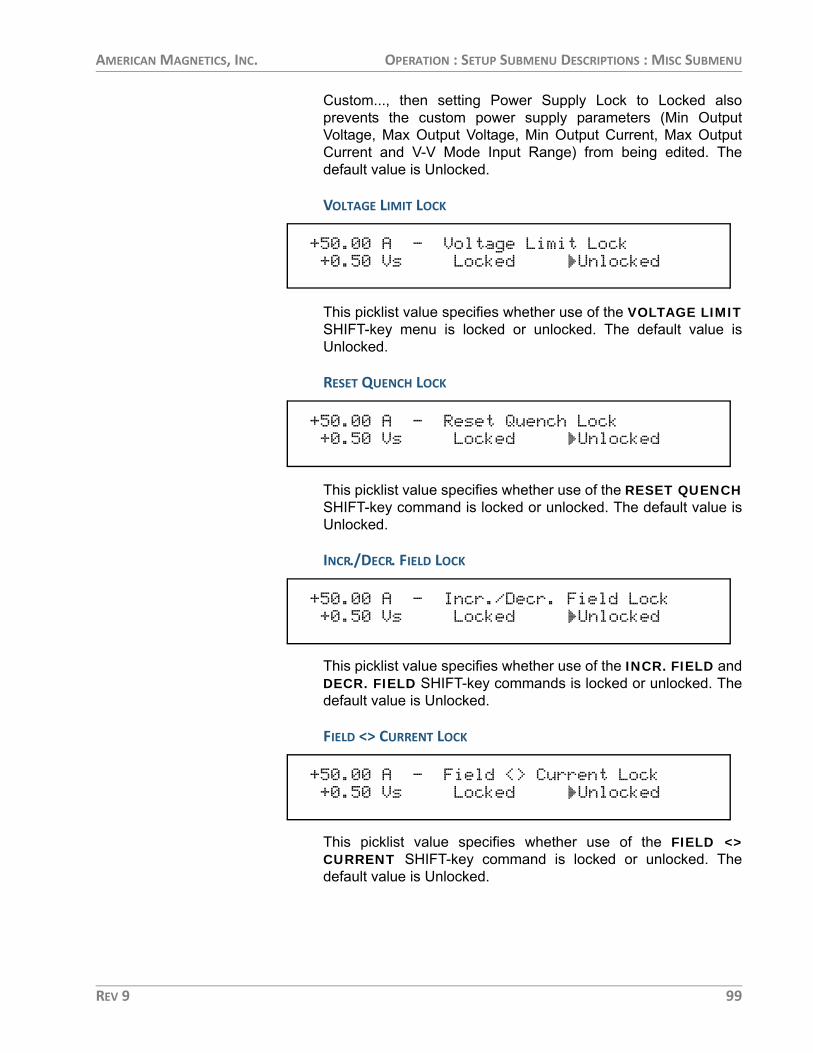
AMERICAN MAGNETICS, INC. OPERATION : SETUP SUBMENU DESCRIPTIONS : MISC SUBMENU
Custom..., then setting Power Supply Lock to Locked alsoprevents the custom power supply parameters (Min OutputVoltage, Max Output Voltage, Min Output Current, Max OutputCurrent and V-V Mode Input Range) from being edited. Thedefault value is Unlocked.
VOLTAGE LIMIT LOCK
This picklist value specifies whether use of the VOLTAGE LIMITSHIFT-key menu is locked or unlocked. The default value isUnlocked.
RESET QUENCH LOCK
This picklist value specifies whether use of the RESET QUENCHSHIFT-key command is locked or unlocked. The default value isUnlocked.
INCR./DECR. FIELD LOCK
This picklist value specifies whether use of the INCR. FIELD andDECR. FIELD SHIFT-key commands is locked or unlocked. Thedefault value is Unlocked.
FIELD <> CURRENT LOCK
This picklist value specifies whether use of the FIELD <>CURRENT SHIFT-key command is locked or unlocked. Thedefault value is Unlocked.
+50.00 A — Voltage Limit Lock+0.50 Vs Locked Unlocked
+50.00 A — Reset Quench Lock+0.50 Vs Locked Unlocked
+50.00 A — Incr./Decr. Field Lock+0.50 Vs Locked Unlocked
+50.00 A — Field <> Current Lock+0.50 Vs Locked Unlocked
REV 9 99

AMERICAN MAGNETICS, INC. OPERATION : SETUP SUBMENU DESCRIPTIONS : MISC SUBMENU
FIELD UNITS LOCK
This picklist value specifies whether the Field Units value islocked or unlocked (whether accessed through the FIELDUNITS key menu or under the Misc submenu). The default valueis Unlocked.
STABILITY SETTING LOCK
This picklist value specifies whether the Stability Mode andStability Setting values are locked or unlocked (whetheraccessed through the STAB. key menu or under the Loadsubmenu). The default value is Unlocked.
INDUCTANCE LOCK
This picklist value specifies whether the Sense MagnetInductance function and Magnet Inductance value are locked orunlocked (under the Load submenu). The default value isUnlocked.
VS <> VM LOCK
This picklist value specifies whether use of the Vs <> Vm SHIFT-key command is locked or unlocked. The default value isUnlocked.
+50.00 A — Field Units Lock+0.50 Vs Locked Unlocked
+50.00 A — Stability Setting Lock+0.50 Vs Locked Unlocked
+50.00 A — Inductance Lock+0.50 Vs Locked Unlocked
+50.00 A — Vs <> Vm Lock+0.50 Vs Locked Unlocked
100 REV 9

AMERICAN MAGNETICS, INC. OPERATION : SETUP SUBMENU DESCRIPTIONS : MISC SUBMENU
VOLT METER LOCK
This picklist value specifies whether use of the VOLT METERSHIFT-key command is locked or unlocked. The default value isUnlocked.
FINE ADJUST LOCK
This picklist value specifies whether use of the FINE ADJUSTSHIFT-key command is locked or unlocked. The default value isUnlocked.
COIL CONSTANT LOCK
This picklist value specifies whether the Coil Constant value(under the Load submenu) is locked or unlocked. The defaultvalue is Unlocked.
CURRENT LIMIT LOCK
This picklist value specifies whether the Current Limit value(under the Load submenu) is locked or unlocked. The defaultvalue is Unlocked.
PSWITCH SETTINGS LOCK
This picklist value specifies whether persistent switch settingsare locked or unlocked. Persistent switch settings protected bythis setting (all under the Switch submenu) are: PSwitch Installed
+50.00 A — Volt Meter Lock+0.50 Vs Locked Unlocked
+50.00 A — Fine Adjust Lock+0.50 Vs Locked Unlocked
+50.00 A — Coil Constant Lock+0.50 Vs Locked Unlocked
+50.00 A — Current Limit Lock+0.50 Vs Locked Unlocked
+50.00 A — PSwitch Settings Lock+0.50 Vs Locked Unlocked
REV 9 101

AMERICAN MAGNETICS, INC. OPERATION : SETUP SUBMENU DESCRIPTIONS : MISC SUBMENU
picklist value, PSwitch Current Detect, PSwitch Current value,PSwitch Transition picklist value, PSwitch Heated Time value,PSwitch Cooled Time value, PSwitch P/S Ramp Rate value, andthe PSwitch P/S Cooling Gain value. The default value isUnlocked.
QUENCH DETECT LOCK
This picklist value specifies whether the Enable Quench Detectpicklist value (under the Protection submenu) is locked orunlocked. The default value is Unlocked.
QUENCH SENSITIVITY LOCK
This picklist value specifies whether the Quench Sensitivitypicklist value (under the Protection submenu) is locked orunlocked. The default value is Unlocked.
ABSORBER PRESENT LOCK
This picklist value specifies whether the Energy AbsorberPresent picklist value (under the Load submenu) is locked orunlocked. The default value is Unlocked.
EXTERNAL RAMPDOWN LOCK
This picklist value specifies whether the external rampdownfunction (under the Protection submenu) is locked or unlocked.The default value is Unlocked.
+50.00 A — Quench Detect Lock+0.50 Vs Locked Unlocked
+50.00 A — Quench Sensitivity Lock+0.50 Vs Locked Unlocked
+50.00 A — Absorber Present Lock+0.50 Vs Locked Unlocked
+0.00 A — External Rampdown Lock+0.50 Vs Locked Unlocked
102 REV 9

AMERICAN MAGNETICS, INC. OPERATION : SETUP SUBMENU DESCRIPTIONS : MISC SUBMENU
DISPLAY BRIGHTNESS LOCK
This picklist value specifies whether the Display Brightnesspicklist value (under the Misc submenu) is locked or unlocked.The default value is Unlocked.
NET SETUP LOCK
This picklist value specifies whether the Net Setup submenu islocked or unlocked. The default value is Unlocked.
OPERATIONAL LIMITS LOCK
This picklist value specifies whether the Operational Limits (thatare a function of input temperature) submenus are locked orunlocked (under the Protection submenu). The default value isUnlocked.
SETTINGS PASSWORD
Settings Password is a password protected submenu under theMisc submenu. It provides a means of changing the settingsprotection password.
When ENTER is pressed to change the settings protectionpassword, the current password must be correctly entered beforea new password can be entered.
+50.00 A — Display Brightness Lock+0.50 Vs Locked Unlocked
+50.00 A — Net Setup Lock+0.50 Vs Locked Unlocked
+50.00 A — Operational Limits Lock+0.50 Vs Locked Unlocked
+50.00 A — Settings Password+0.50 Vs Change Password
+50.00 A — Enter Current Password*+0.50 Vs _
REV 9 103
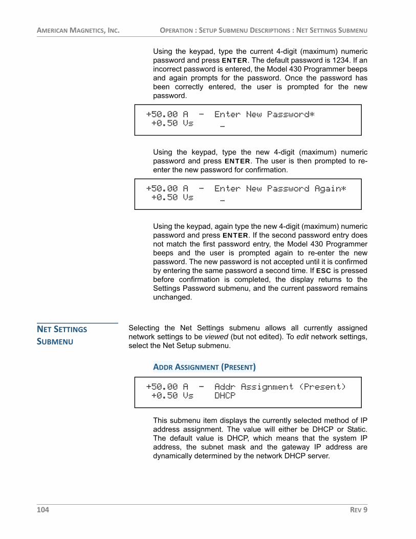
AMERICAN MAGNETICS, INC. OPERATION : SETUP SUBMENU DESCRIPTIONS : NET SETTINGS SUBMENU
Using the keypad, type the current 4-digit (maximum) numericpassword and press ENTER. The default password is 1234. If anincorrect password is entered, the Model 430 Programmer beepsand again prompts for the password. Once the password hasbeen correctly entered, the user is prompted for the newpassword.
Using the keypad, type the new 4-digit (maximum) numericpassword and press ENTER. The user is then prompted to re-enter the new password for confirmation.
Using the keypad, again type the new 4-digit (maximum) numericpassword and press ENTER. If the second password entry doesnot match the first password entry, the Model 430 Programmerbeeps and the user is prompted again to re-enter the newpassword. The new password is not accepted until it is confirmedby entering the same password a second time. If ESC is pressedbefore confirmation is completed, the display returns to theSettings Password submenu, and the current password remainsunchanged.
NET SETTINGS SUBMENU
Selecting the Net Settings submenu allows all currently assignednetwork settings to be viewed (but not edited). To edit network settings,select the Net Setup submenu.
ADDR ASSIGNMENT (PRESENT)
This submenu item displays the currently selected method of IPaddress assignment. The value will either be DHCP or Static.The default value is DHCP, which means that the system IPaddress, the subnet mask and the gateway IP address aredynamically determined by the network DHCP server.
+50.00 A — Enter New Password*+0.50 Vs _
+50.00 A — Enter New Password Again*+0.50 Vs _
+50.00 A — Addr Assignment (Present)+0.50 Vs DHCP
104 REV 9

AMERICAN MAGNETICS, INC. OPERATION : SETUP SUBMENU DESCRIPTIONS : NET SETTINGS SUBMENU
SYSTEM NAME (PRESENT)
This submenu item displays the currently assigned system name(also known as host name or computer name), the name bywhich the Model 430 Programmer is identified on a network. Thissetting can only be modified using remote communications(either Ethernet or RS-232); it cannot be edited using the frontpanel keypad.
IP ADDRESS (PRESENT)
This submenu item displays the currently assigned system IPaddress for the Model 430 Programmer. The value inparentheses after the IP address value indicates how the IPaddress is assigned. DHCP indicates that the value isdynamically assigned by a DHCP server; Static indicates that thevalue is static, assigned by the Model 430 user. The default valueis 0.0.0.0. However, since the default method of IP addressassignment is by DHCP server, this value is typically set by thenetwork DHCP server.
SUBNET MASK (PRESENT)
This submenu item displays the currently assigned subnet maskfor the Model 430 Programmer. The value in parentheses afterthe subnet mask value indicates how the subnet mask isassigned. DHCP indicates that the value is dynamically assignedby a DHCP server; Static indicates that the value is static,assigned by the Model 430 user. The default value is 0.0.0.0.However, since the default method of subnet mask assignment isby DHCP server, this value is typically set by the network DHCPserver.
+50.00 A — System Name (Present)+0.50 Vs AMI
+50.00 A — IP Address (Present)+0.50 Vs 0.0.0.0 (DHCP)
+50.00 A — Subnet Mask (Present)+0.50 Vs 0.0.0.0 (DHCP)
REV 9 105

AMERICAN MAGNETICS, INC. OPERATION : SETUP SUBMENU DESCRIPTIONS : NET SETUP SUBMENU
GATEWAY ADDRESS (PRESENT)
This submenu item displays the currently assigned gateway IPaddress for the Model 430 Programmer. The value inparentheses after the gateway IP address value indicates howthe gateway IP address is assigned. DHCP indicates that thevalue is dynamically assigned by a DHCP server; Static indicatesthat the value is static, assigned by the Model 430 user. Thedefault value is 0.0.0.0. However, since the default method ofsubnet mask assignment is by DHCP server, this value istypically set by the network DHCP server.
NET SETUP SUBMENU Selecting the Net Setup submenu allows network settings to be edited(except for the system name, which can only be modified using remotecommunications). Note also that the system IP address, the subnetmask and the gateway IP address can only be assigned by the user ifthe currently selected method of IP address assignment is Static; if thecurrently selected method of IP address assignment is DHCP, then thesethree values will be set by the network DHCP server.
IP ADDRESS ASSIGNMENT
This picklist value specifies method of IP address assignment.The value can be set to either DHCP or Static. If the value isDHCP, then the system IP address, the subnet mask and thegateway IP address are dynamically assigned by the networkDHCP server. If the value is Static, then the system IP address,the subnet mask and the gateway IP address are assigned staticvalues by the user. The default value is DHCP.
NOTE If the IP Address Assignment value is changed, the Model 430 Programmer power must be cycled off for at least 15 seconds and then back on to complete the change. The previous value will continue to be used until the Model 430 is restarted.
+50.00 A — Gateway Address (Present)+0.50 Vs 0.0.0.0 (DHCP)
+50.00 A — IP Address Assignment+0.50 Vs DHCP Static
106 REV 9

AMERICAN MAGNETICS, INC. OPERATION : SETUP SUBMENU DESCRIPTIONS : NET SETUP SUBMENU
SYSTEM IP ADDRESS
If IP Address Assignment is Static, then the system IP address can be assigned by the user. The default value is 0.0.0.0.
NOTE This item is only available in the Net Setup submenu if IP Address Assignment is Static. If IP Address Assignment is DHCP, the system IP address is assigned by the network DHCP server and cannot be assigned by the user.
SUBNET MASK
If IP Address Assignment is Static, then the subnet mask can be assigned by the user. The default value is 0.0.0.0.
NOTE This item is only available in the Net Setup submenu if IP Address Assignment is Static. If IP Address Assignment is DHCP, the subnet mask is assigned by the network DHCP server and cannot be assigned by the user.
GATEWAY IP ADDRESS
If IP Address Assignment is Static, then the gateway IP address can be assigned by the user. The default value is 0.0.0.0.
NOTE This item is only available in the Net Setup submenu if IP Address Assignment is Static. If IP Address Assignment is DHCP, the gateway IP address is assigned by the network DHCP server and cannot be assigned by the user.
+50.00 A — System IP Address+0.50 Vs 0.0.0.0
+50.00 A — Subnet Mask+0.50 Vs 0.0.0.0
+50.00 A — Gateway IP Address+0.50 Vs 0.0.0.0
REV 9 107

AMERICAN MAGNETICS, INC. OPERATION : EXAMPLE SETUP : NET SETUP SUBMENU
EXAMPLE SETUP
As a precursor to operating a superconducting magnet with the Model430 Programmer and power supply, all of the setup items should bereviewed and set if necessary with appropriate values for the connectedsuperconducting magnet.
The figure at left shows an exam-ple magnet specifications sheet.Several parameters needed tooperate the magnet are specified.These values should be enteredinto the appropriate setup menu ofthe Model 430 Programmer. Forthe purposes of this example, theAMI Model 4Q06125PS powersupply will be assumed, sincerated current for the example mag-net is 85.6 A.
The Current Limit accessible in theProtection submenu should be setto the rated current to preventaccidental operation of the magnetabove rated field/current. Themagnet specification sheet alsoindicates whether a persistentswitch is installed and provides therecommended heating current. Thepersistent switch information isentered in the Switch submenu.
If your magnet, Model 430Programmer, and power supplywere purchased as a system fromAMI, the setup menus are presetby AMI to match the magnetpurchased.
EXCELLENCE IN MAGNETICS AND CRYOGENICS
American Magnetics, Inc.P.O. Box 2509, 112 Flint Road, Oak Ridge, TN 37831-2509Phone: (865) 482-1056 Fax: (865) 482-5472Internet: http://www.americanmagnetics.com E-mail: [email protected]
AMI JOB # MAGNET #
TYPE:
MODEL:
FOR:
DATE:
Rated Central Field @ 4.2K1---------------------------------
Rated Current ------------------------------------------
Max. Field Tested ------------------------------------------
Field to Current Ratio -----------------------------
Homogeneity over a 1 cm DSV --------------------------------
Measured Inductance -----------------------------------
Charging Voltage ---------------------------------------
Axial Clear Bore --------------------------------------
Overall Length (flange to flange) --------------------
Maximum Outside Diameter ------------------------------
Weight ---------------------------------------------------
Recommended Persistent Switch Heater Current ---------------
Persistent Switch Heater Nominal Resistance2------------
Magnet Resistance in Parallel with Switch2--------------
Mounting:
1. Magnet not warranted for operation above 80 kG.2. All resistance measurements made at room temperature.
Example Magnet Specification Sheet
108 REV 9

AMERICAN MAGNETICS, INC. OPERATION : EXAMPLE SETUP
The table below provides a summary of the Model 430 Programmersetup parameters for this example.
Example Setup Configuration
Parameter Setting
Select Supply AMI 4Q06125PS
Stability Mode Auto
Coil Constanta (kG/A)
a. Also referred to as the Field-to-Current Ratio. Obtained by dividing the rated field by the rated current if not explicitly stated.
0.934
Inductance (H) 9.7
Energy Absorber Present NO
PSwitch Installed YES
PSwitch Current (mA) 41.0
PSwitch Heated Time (sec) 20
PSwitch Cooled Time (sec) 20
PSwitch P/S Ramp Rate (A/sec) 10
PSwitch Cooling Gain (%) 0.0%
Current Limit (A) 85.600
Enable Quench Detect YES
Extern Rampdown Enabled YES
Voltage Limit (V) 3.500b
b. Value is the 2.1 V charge rate plus allowances for power lead drop (typically about 10-20 milliohms) at the rated current. If a Model 601 energy absorber(s) is present, add an additional 5 V to the value.
Ramp Rate (A/sec) 0.2165c
c. Value is obtained by dividing the magnet charging voltage (V) by the magnet inductance (H).
REV 9 109

AMERICAN MAGNETICS, INC. OPERATION : RAMPING FUNCTIONS
RAMPING FUNCTIONS
The ramping functions are used to control charging of thesuperconducting load. The Model 430 Programmer allows piecewise-linear charging profiles to be defined and executed (up to 10 segments,each with a unique ramp rate). The basic charging equation for asuperconducting magnet is:
where V is the charging voltage (V), L is the magnet inductance (H), anddi/dt is the ramp rate (A/s). The relationship may also be defined in termsof a ramp rate in kG/s by the relationship:
where C is the coil constant (or field-to-current ratio) in kG/A, and dB/dtis the ramp rate expressed in kG/s.
A desired ramp rate should be selected by the user and entered into theModel 430 Programmer. A Voltage Limit should also be specified that isgreater than or equal to the voltage calculated from the equations aboveplus energy absorber voltage (if installed) plus power lead voltage drop(usually less than 2 V).
Once the ramp rate and Voltage Limit are specified, the Model 430Programmer provides two modes of ramping: manual and automatic.Manual ramping will ramp to the Current Limit via manual directioncontrol by the user. Automatic ramping will ramp to the target field/current automatically. Automatic ramping can be thought of as a “nextpoint” operation, whereby the Model 430 determines the appropriateramp direction based on the present magnet current and the targetvalue.
NOTE You may enter up to 10 digits beyond the decimal point within the ramping control menus. These extra digits are maintained in the internal memory of the Model 430 Programmer even though the full precision is not displayed after entry.
RAMPING STATES AND CONTROLS
The ramping state may be one of several values as described in thetable below.
If the RAMP / PAUSE key is pressed while ramping, the PAUSED modebecomes active. To begin automatic ramping, press the RAMP / PAUSEkey to deactivate the PAUSED mode. If manual ramping is desired, use
V L idtd
----=
V LC---- Bd
td------=
110 REV 9

AMERICAN MAGNETICS, INC. OPERATION : RAMPING FUNCTIONS
either the INCR. FIELD or DECR. FIELD SHIFT+keys for manualcontrol of ramping up or ramping down, respectively.
Voltage limit and ramp rate may be specified from quickly accessibleSHIFT+key menus from the front panel keypad44. The settings forVoltage Limit and ramp rate(s) are applicable to both manual andautomatic ramping.
MANUAL RAMPING The INCR. FIELD and DECR. FIELD SHIFT+key functions controlmanual ramping. Manual ramping ramps field/current up or down at thedefined ramp rate(s). See page 67 for details regarding the use of theseSHIFT+key functions.
AUTOMATIC RAMPING Automatic ramping differs from manual ramping in that the Model 430Programmer automatically performs ramping in the appropriate directionto achieve the value of the target field/current setting. To use automaticramping, enter the target field/current with which ramping is desired45. If
Ramp modes and descriptions.
Mode Description
Ramping Automatic ramping to the target field/currenta is in progress.
Holding The target field/current has been achieved and is being maintained.
Paused Ramping is suspended at the field/current achieved at the time the PAUSED mode was entered.
Manual Up/Down Ramping is being controlled by the manual control (INCR. FIELD and DECR. FIELD) SHIFT-key functions available on the front panel.
Zeroing Current RAMP TO ZERO is active, and the Model 430 Programmer is ramp-ing current to 0 A.
Zero Current RAMP TO ZERO is still active, and the current is less than 0.1% of Imax.
Heating Switch The persistent switch heater has been activated. Ramping is disabled during the persistent switch heating period.
Cooling Switch The persistent switch heater has been deactivated. Ramping is disabled during the persistent switch cooling period.
External RampdownAn external rampdown has been triggered. The system will rampdown using any defined rampdown ramp rates and cannot be interrupted until zero current is achieved.
a. The target field/current setting is discussed on page 61.
44. Refer to on page 63 and on page 66.
REV 9 111

AMERICAN MAGNETICS, INC. OPERATION : RAMPING FUNCTIONS
ramping is not PAUSED, ramping to the target field/current beginsimmediately. If ramping is PAUSED, ramping to the target field/currentwill begin when the RAMP / PAUSE key is pressed to take the Model430 Programmer out of PAUSED mode. The ramp rate will be controlledby the preset ramp rate variables as described in on page 63.
RAMPING TO ZERO Pressing the RAMP TO ZERO key activates an immediate ramp to zerofield/current. See page 62 for details. Use the feature to zero the field/current instead of setting the target field/current to a value of zero.
FINE ADJUST OF FIELD / CURRENT IN HOLDING MODE
If the target field/current menu is active and the Model 430 Programmeris in HOLDING mode (indicated by a “–” Status Indicator), the fine adjustknob can be used to manipulate the output current. While at the targetfield/current menu, press SHIFT, followed by FINE ADJUST. This willallow fine adjustment of the field/current (see page 69).
When the fine adjust knob is turned the Model 430 Programmer willfollow the target current as it is adjusted, at the defined ramp rate for thesegment in which it is operating. Adjustment of the current is preventedfrom exceeding the Current Limit specified in the Load setup menu (seepage 88). The resolution of the adjustment is 15 digits, which is greaterthan the resolution of the display.
When the field/current is adjusted to the desired value, press the ENTERkey to keep that value as the target field/current. If any other operation isperformed before ENTER is pressed, the target field/current value willrevert back to what it was before adjustment using the fine adjust knobwas initiated, and the current will immediately begin ramping back to thatvalue.
45. See page 61.
+20.02 A - Target Current (A)+0.20 Vs +20.0239
112 REV 9

AMERICAN MAGNETICS, INC. OPERATION : PERSISTENT SWITCH CONTROL
PERSISTENT SWITCH CONTROL
The Model 430 Programmer includes an integral persistent switch heaterthat provides the capability of controlling the persistent mode of themagnet either locally from the front panel of the Model 430 Programmerusing the PERSIST. SWITCH CONTROL key46, or remotely through acommunications interface. The persistent mode of the magnet isindicated by the MAGNET IN PERSISTENT MODE LED47.
See page 58 for details of the use of the PERSIST. SWITCH CONTROLkey.
NOTE The following procedures include several automatically sequenced steps once initiated. It is possible to interrupt the process at any point by pressing the SHIFT+ESC keys. Please note that the state in which the system will remain after this interruption depends on the specific active step during which the SHIFT+ESC was pressed. Use this abort override keystroke with caution.
PROCEDURE FOR INITIAL HEATING OF THE SWITCH
The Model 430 Programmer remembers the state of the persistentswitch during the time that the Programmer is de-energized. If the Model430 is turned on when its shut down state was such that the persistentswitch was heated and commanding zero current (the normal state afterthe magnet is discharged), the following screen will be displayed.
In order to charge the magnet, the persistent switch heater must beenergized. Perform the following steps.
46. See page 58.47. See page 70.
0.00 A P Mode: Paused 0.00 Vs PSwitch Heater: OFF
REV 9 113

AMERICAN MAGNETICS, INC. OPERATION : PERSISTENT SWITCH CONTROL
1. Turn on the persistent switch heater by pressing the PERSIST. SWITCH CONTROL key to heat the persistent switch heater.
NOTE If the PSwitch Transition setting48 is set to Timer, the number in parentheses in the display indicates the number of seconds remaining in the timer countdown. If the PSwitch Transition setting is set to Magnet Voltage, the number in parentheses is the running magnet voltage variance. For the magnet voltage-based switch transition, a variance value of zero indicates the switch is in the cooled state.
2. After the persistent switch heater has been heated for the preset heating time specified by the PSwitch Heated Time setting, or a transition is detected by the magnet voltage-based option, the display will show the default display and wait at zero current for a command from the operator. The magnet is no longer isolated from the power supply output.
PROCEDURE FOR ENTERING PERSISTENT MODE
In order to enter the persistent mode of magnet operation, the usershould perform the following steps:1. Use either automatic or manual ramping to achieve the desired field or cur-
rent in the magnet.
2. The Model 430 Programmer must be in either the HOLDING or PAUSED mode at the target field or current.
3. The Model 430 Programmer must be at the default field/current display.49
4. Press the PERSIST. SWITCH CONTROL key to turn off the persistent switch heater and automatically ramp the power supply to zero current:
a. After the PERSIST. SWITCH CONTROL key is pressed, the Model 430 Programmer requests that the ENTER key be pressed as
48. Refer to page 85.
0.00 A Mode: Heating Switch (4) 0.00 Vs PSwitch Heater: ON
0.00 A P Mode: Paused 0.00 Vs PSwitch Heater: ON
49. Refer to page 51.
114 REV 9

AMERICAN MAGNETICS, INC. OPERATION : PERSISTENT SWITCH CONTROL
a confirmation that the magnet should be placed in persistent mode.50
b. When ENTER is pressed, the persistent switch is cooled for the preset persistent switch cooling time (set by the PSwitch Cooled Time51). The display indicates that the persistent switch is being cooled and indicates the number of seconds (4 in this example) remaining in the cooling cycle for timer-based switch transitions, or optionally indicates the running variance of the magnet voltage for magnet voltage-based switch transitions.
NOTE For the magnet voltage-based switch transitions, a variance value of zero indicates a cooled switch. Therefore, during the cooldown the display will show a seemingly random sequence of numbers that should gradually decrease and eventually decay to a value of zero. Once the variance remains at zero for at least five seconds, the switch will be considered cooled.
c. When the cooled time is complete, the green MAGNET IN PERSISTENT MODE LED will illuminate and the power supply will ramp to zero at the PSw P/S Ramp Rate value52.
NOTE The magnet voltage (Vm) is monitored during the power supply ramp to zero. For a cooled switch, the magnet voltage should remain at zero. The following steps d through f apply only if the magnet voltage does not remain at zero.
50. Pressing the ESC key will terminate the command and return the Model 430 Programmer to the default screen.
51. Refer to on page 86 for timer-based switch transitions.52. Refer to on page 87.
+50.00 A - Press ENTER to begin 0.00 Vm Persistent Mode
+50.00 A Mode: Cooling Switch (4)+0.01 Vm PSwitch Heater: OFF
+42.89 A Mode: Power Supply ramping 0.00 Vm to zero current
REV 9 115

AMERICAN MAGNETICS, INC. OPERATION : PERSISTENT SWITCH CONTROL
d. If the magnet voltage exceeds 0.5 V during this ramp to zero, the Model 430 Programmer beeps to indicate the persistent switch did not transition to the superconducting state. The Model 430 will then turn the switch heater back on immediately and then begin ramping the field/current back to the value before the present cooling cycle initiation:
NOTE The ramp back to the value before the cooling cycle was initiated can be interrupted at any time by pressing the RAMP/PAUSE key. The ramping will then PAUSE and hold.
e. When the field/current reaches the value before the cooling cycle initiation, the display will indicate the persistent mode transition malfunction:
f. After pressing ENTER, the Model 430 Programmer will revert to the default field/current display.
5. If there is no magnet voltage error during the rampdown, and after the power supply is finished ramping to zero, the following screen will be displayed:
NOTE If desired, press the ESC key in the above display to return the Model 430 Programmer to the default display.
+45.39 A Mode: Power Supply Ramping+1.52 Vm to match magnet field
+50.00 A - Mode: Paused w/PSW error+0.06 Vm Press ENTER to continue
+50.00 A P Mode: Paused+0.00 Vm PSwitch Heater: ON
0.00 A - Magnet in Persistent Mode 0.00 Vm Press PER.SW.CTRL. to exit
0.00 A - Mode: Zero Current 0.00 Vm PSwitch Heater: OFF
116 REV 9

AMERICAN MAGNETICS, INC. OPERATION : PERSISTENT SWITCH CONTROL
NOTE Refer to page 61 for the procedure to display the magnet current that was established when the persistent switch was cooled.
6. If desired, the power supply system can be de-energized. Turn the power supply off first followed in a few seconds by the Model 430 Programmer.
NOTE The Model 430 Programmer will store the state of the magnet in memory and assist the user in exiting the persistent mode when the Model 430 Programmer is next turned on (discussed in the following paragraphs).
PROCEDURE FOR EXITING PERSISTENT MODE
To exit the persistent mode of magnet operation, the user should performthe following steps:1. If the Model 430 Programmer has not been powered off since the magnet
was placed in persistent mode, proceed to step 3.
2. If the Model 430 Programmer has been powered off since the magnet was placed in persistent mode, complete the following steps (a) and (b) below before proceeding to step 3.
a. Energize the Model 430 and wait for the prompt on the Model 430 display and then energize the power supply.
After the power supply has been on for a few seconds53, press ENTER to clear the Model 430 screen prompt.
b. When ENTER is pressed, the display will indicate that the magnet was in persistent mode54 when the Model 430 Programmer was turned off (and display the magnet current that was established when the persistent switch was cooled).
53. If the power supply is an AMI 4Q06125PS Type, wait for the audible click of the relay before pressing ENTER on the Model 430.
54. The MAGNET IN PERSISTENT MODE LED will also be illuminated.
0.00 A P Turn on power supply 0.00 Vs Press ENTER to continue
Magnet in Persistent Mode (13.5A). UsePERSIST SWITCH CONTROL to exit Per. Mode
REV 9 117
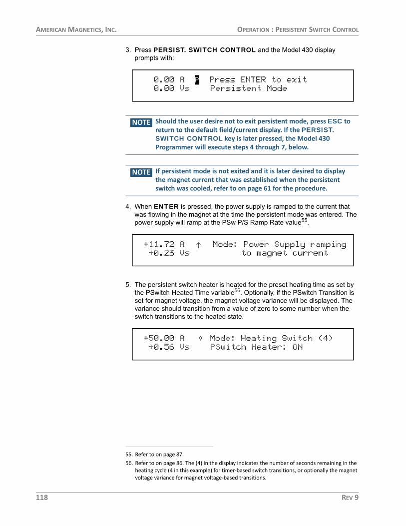
AMERICAN MAGNETICS, INC. OPERATION : PERSISTENT SWITCH CONTROL
3. Press PERSIST. SWITCH CONTROL and the Model 430 display prompts with:
NOTE Should the user desire not to exit persistent mode, press ESC to return to the default field/current display. If the PERSIST. SWITCH CONTROL key is later pressed, the Model 430 Programmer will execute steps 4 through 7, below.
NOTE If persistent mode is not exited and it is later desired to display the magnet current that was established when the persistent switch was cooled, refer to on page 61 for the procedure.
4. When ENTER is pressed, the power supply is ramped to the current that was flowing in the magnet at the time the persistent mode was entered. The power supply will ramp at the PSw P/S Ramp Rate value55.
5. The persistent switch heater is heated for the preset heating time as set by the PSwitch Heated Time variable56. Optionally, if the PSwitch Transition is set for magnet voltage, the magnet voltage variance will be displayed. The variance should transition from a value of zero to some number when the switch transitions to the heated state.
55. Refer to on page 87.56. Refer to on page 86. The (4) in the display indicates the number of seconds remaining in the
heating cycle (4 in this example) for timer-based switch transitions, or optionally the magnet voltage variance for magnet voltage-based transitions.
0.00 A P Press ENTER to exit 0.00 Vs Persistent Mode
+11.72 A Mode: Power Supply ramping+0.23 Vs to magnet current
+50.00 A Mode: Heating Switch (4)+0.56 Vs PSwitch Heater: ON
118 REV 9

AMERICAN MAGNETICS, INC. OPERATION : PERSISTENT SWITCH CONTROL
NOTE The magnet voltage (Vm) is monitored during the switch heating cycle. If the voltage is greater than 0.5 V, the Model 430 Programmer will beep and display a message to indicate a mismatch between the magnet current and power supply current.
NOTE This mismatch in current indicates the magnet current (and therefore the field) has decayed significantly during the time the magnet was in persistent mode. Since this is not a critical error57, the screen will change back to the default display typically at some field/current less than the last recorded persistent value.
6. After the Model 430 Programmer has completed this persistent switch heat-ing operation, the display reads:
7. After ENTER is pressed, the default field/current status screen is displayed with the power supply in the pause mode:
57. This current mismatch could be indicative of a problem with the magnet persistent joints.
+50.00 A Mode: Heating Switch (4)+0.86 Vm *** Current Mismatch ***
+47.59 A P Mode: Paused 0.00 Vm PSwitch Heater: ON
+50.00 A P Mode: Magnet in Driven Mode 0.00 Vm Press ENTER to continue
+50.00 A P Mode: Paused 0.00 Vm PSwitch Heater: ON
REV 9 119

AMERICAN MAGNETICS, INC. OPERATION : PERSISTENT SWITCH CONTROL
TOGGLING THE STATE OF THE PERSISTENT SWITCH HEATERThe state of the persistent switch can be toggled by pressing SHIFT and then the PERSIST. SWITCH CONTROL key. By toggling the state of the heater in this manner, there will be no power supply ramping or other automatic functions.
ENTERING PERSISTENT MODE WITHOUT AUTOMATIC RAMP TO ZERO
1. Place the Model 430 Programmer in the HOLDING or PAUSED mode at the desired field or current.
2. Press the SHIFT and then the PERSIST. SWITCH CONTROL key to turn off the persistent switch heater current. Note that the Model 430 Programmer will enter the COOLING SWITCH mode and disallow any ramping during the switch cooling period.
3. If magnet current is greater than ~0.1% of the power supply maxi-mum output current when the switch heater current is turned off, the MAGNET IN PERSISTENT MODE LED will illuminate.
EXITING PERSISTENT MODE WITHOUT AUTOMATIC RAMP TO LAST KNOWN PERSISTENT MAGNET CURRENT
CAUTION To avoid damage to the magnet or triggering protection circuits on the magnet, the current in the power supply should match the current that was flowing in the magnet when the persistent mode was entered.
NOTE For the procedure to display the magnet current that was established when the persistent switch was cooled, refer to page 61.
1. Place the Model 430 Programmer in the HOLDING or PAUSED mode at the desired field or current.
2. Press the SHIFT and then the PERSIST. SWITCH CONTROL key to turn on the persistent switch heater current. Note that the Model 430 Programmer will enter the HEATING SWITCH mode and disallow any ramping during the switch heating period.
3. At the end of the switch heating period, the MAGNET IN PER-SISTENT MODE LED will be turned off and the Model 430 Pro-grammer will be in the PAUSED mode.
120 REV 9

AMERICAN MAGNETICS, INC. OPERATION : RAMPING FUNCTIONS EXAMPLE
RAMPING FUNCTIONS EXAMPLE
As an example of ramping to two target field/current settings, refer tofigure below. Each step is labeled as 1 through 8. The Model 430Programmer, for the purposes of the example, is assumed to be in thePAUSED mode at 0 A at the beginning of the ramping example.
Point 1. The current is 0 A and the Model 430 Programmer is in thePAUSED mode. The user sets the target field/current to -28.000 A. TheRAMP / PAUSE key is pressed so that the PAUSED mode is no longeractive and the Model 430 begins ramping current.
Point 2. The target field/current setting of -28.000 A is achieved and theModel 430 Programmer switches to HOLDING mode.
Point 3. The user changes the ramp rate setting. The user also sets anew value of +40.000 A for the target field/current. As soon as the newtarget field/current is entered, the Model 430 Programmer automaticallybegins ramping at the specified ramp rate.
Point 4. The user presses the RAMP / PAUSE key at a current of 25.15A and the PAUSED mode is activated. The Model 430 Programmermaintains the current in the PAUSED mode.
Point 5. The user presses the RAMP / PAUSE key once again to resumeramping.
Ramping to Two Different Target Field/Current Settings
1
4
6 7
8
2 3
TARGET CURRENT 1
50 A
-50 A
TARGET CURRENT 2
Time
5
6a 6d
6b 6c
REV 9 121

AMERICAN MAGNETICS, INC. OPERATION : RAMPING FUNCTIONS EXAMPLE
Point 6. The target field/current setting of +40.000 A is achieved and theModel 430 Programmer switches to HOLDING mode. At this point theuser deactivates the persistent switch heater by pressing the PERSIST.SWITCH CONTROL key, which removes the magnet from the circuit.
Point 6a. The dashed line between point 6a and 6b is the rapid rampingdown of the power supply current which automatically happens after thePSwitch Cooled Time has elapsed. Note that the magnet currentremains at the Point 6 value when the magnet was placed in persistentmode.
Point 6c. The user presses the PERSIST. SWITCH CONTROL keywhich rapidly ramps the power supply output to the current that is flowingin the magnet. The power supply matches the magnet current at point6d.
Point 7. The user again increases the ramp rate and presses the RAMPTO ZERO key to begin ramping to zero current. The Model 430Programmer automatically ramps the current to 0 A.
Point 8. The Model 430 Programmer switches to ZERO CURRENTmode at 0 A current when achieved and holds at this current until furthercommands are issued by the user.
122 REV 9

AMERICAN MAGNETICS, INC. OPERATION : QUENCH DETECTION
QUENCH DETECTION
The Model 430 Programmer continuously monitors the superconductingmagnet load and can automatically detect a field/current quenchcondition. If a quench is detected, the MAGNET QUENCH LED will beilluminated and the display will appear as shown below.
QUENCH DETECTION METHOD
The primary method for quench detection is a continual internalcomparison between the reference current and the measured current. Ifthe measured current for the system develops a mismatch to thereference (i.e. the desired control value), then if the mismatch exceeds apredefined margin a quench detection will trigger.
Optionally, if the Model 430 is configured for external temperature input,the quench detection logic can utilize a measured temperature (such asfrom a cold head of a cryogenic refrigerator). If the measuredtemperature exceeds some predefined safe limit, the Model 430 willtrigger a quench detection.
The Model 430 may also be configured to use both the current mismatchand temperature detection methods and trigger a quench if eitherindicate a problem.
NOTE The Model 430 quench detection features should never be relied upon as the primary quench safing for any magnet system. The purpose of the Model 430 quench detection is simply to avoid dumping any additional energy into a magnet system that has already quenched. The only action the Model 430 can take is to force the power supply voltage output to zero volts and hold. Superconducting magnets should be internally designed to be safe in the event of a quench without any input from the Model 430.
When a quench is detected, the Model 430 automatically sets the powersupply output voltage to zero volts, provides a quench output signal (drycontacts) to the rear panel Quench I/O connector (see page 199 of theAppendix for the connector pinout), and will not respond to further inputuntil the RESET QUENCH (SHIFT+3) key is used to clear the quench
+44.36 A Quench Detect @ +80.56 A0.00 Vs PSwitch Heater: ON
REV 9 123

AMERICAN MAGNETICS, INC. OPERATION : QUENCH DETECTION
detect condition, or until the quench condition is cleared by a remotecommand.
If the RESET QUENCH key has been locked58, the user will be asked toenter the password to clear the quench. The entry of this password willnot unlock this reset quench feature, but will only reset the currentquench event so operation may resume. Enter the password followed bythe ENTER key to reset the quench and continue.
When the RESET QUENCH key is used to clear the quench condition ora remote clear command is issued, the Model 430 Programmer willautomatically enter the PAUSED mode and will attempt to maintain thecurrent present at the point the quench condition was cleared.
EXTERNAL QUENCH DETECTION
The rear panel Quench I/O connector provides pins for external quenchinput (contact closure — see page 199 of the Appendix for the connectorpinout). If the quench input is asserted, then the Model 430 Programmerinterprets this input as indication of a quench condition and the Model430 automatically sets the power supply output voltage to zero and willnot respond to further input until the RESET QUENCH key is used toclear the quench detect condition, or until the quench condition iscleared by a remote command. The rear panel input cannot be disabled;however, it may be left disconnected without the possibility of agenerating a false quench condition.
NOTE If the external quench detection circuit continues to assert the quench detection input of the Model 430 Programmer, the RESET QUENCH (SHIFT+3) key will be unable to clear the quench condition.
DISABLING INTERNAL QUENCH DETECTION
The internal quench detection feature may be disabled in the Loadsubmenu59. However, the rear panel Quench I/O connector outputremains active at all times.
58. See page 99.
+44.36 A Enter Password*0.00 Vs _
59. See page 89.
124 REV 9

AMERICAN MAGNETICS, INC. OPERATION : EXTERNAL RAMPDOWN
If the internal quench detection feature is disabled, the Model 430Programmer attempts to limit the error between the commanded currentand the present current to a value that will not result in excessivevoltages being introduced across the magnet terminals. Under mostoperating conditions this will not damage any internal protection circuitsof the magnet. If an actual quench condition occurs, the Model 430 willfollow the magnet current to zero unless the user intervenes.
If the rear panel Quench I/O connector is asserted, the Model 430 willforce the power supply output to zero volts regardless of whether theinternal quench detection is enabled or disabled.
In the event that the persistent switch becomes normal without user orremote activation of the switch heater control, the Model 430Programmer will match the magnet current and attempt to stabilize theload if the internal quench detection feature is disabled. If the internalquench detection feature is enabled, then this event will generally triggerthe quench detection logic if a difference exists between the magnetcurrent and the real-time setpoint current of the Model 430.
EXTERNAL RAMPDOWN
This feature60 is useful in any application requiring magnet rampdown inresponse to any external event that can be signaled by the closure of apair of electrical contacts61.
The user input for initiating external rampdown is provided on the rearpanel of the Model 430 Programmer. The process is started by shorting,for at least 10 milliseconds, the input connections through closure ofuser-supplied external contacts. Once triggered, rampdown of themagnetic field of the magnet is initiated.
NOTE Operator intervention (such as RAMP|PAUSE, ESC, SHIFT+ESC, etc.) is inhibited until rampdown is completed and the external rampdown signal is cleared. There is no abort function provided, however the quench detection feature of the Model 430 remains active during the rampdown.
The external rampdown feature is ideally suited for use with AMI’s Model1700 with the liquid helium level monitor option in wet magnet systems.The Model 1700 has externally accessible normally-open relay contactsthat close whenever the liquid helium level drops below a preset level.
60. When enabled. See page 94.61. Refer to page 200. The contact closure time must be at least 10 milliseconds to ensure it
doesn’t fall between the sampling points of the Model 430 Programmer.
REV 9 125

AMERICAN MAGNETICS, INC. OPERATION : EXTERNAL RAMPDOWN
When connected to the Model 430 Programmer, these contacts cansignal the Model 430 to safely and automatically ramp the magnet fieldto zero, thereby preventing a magnet quench due to low liquid heliumlevel in the system.
EXTERNAL RAMPDOWN WHILE IN PERSISTENT MODE
The following steps and associated screen displays describe theprocess that occurs after external rampdown is initiated while themagnet is in persistent mode:1. The Model 430 Programmer first ramps the power supply to the magnet cur-
rent.
2. Once the power supply is at the magnet current, the FIELD AT TARGET LED will light and the unit will momentarily “hold”:
3. Following a short “hold”, the persistent switch will be heated to place the power supply in control of magnet current:
4. After heating (turning off) the persistent switch, the MAGNET IN PER-SISTENT MODE LED extinguishes, and rampdown begins. The FIELD AT TARGET LED extinguishes.
5. After rampdown, the following will display:
+3.92 A Mode: Ramping+0.17 Vs PSwitch Heater: OFF
+50.00 A - Mode: Holding+0.65 Vs PSwitch Heater: OFF
+50.00 A Mode: Heating Switch (4)+0.67 Vs PSwitch Heater: ON
+48.85 A Ext. Rampdown in progress-1.68 Vs PSwitch Heater: ON
0.00 A - Ext. Rampdown completed 0.00 Vs Press ENTER to continue
126 REV 9

AMERICAN MAGNETICS, INC. OPERATION : EXTERNAL RAMPDOWN
NOTE The external rampdown signal MUST be cleared before pressing ENTER will yield a response. Further operator control is inhibited until the external rampdown signal is cleared.
6. Once the external signal has been cleared, ENTER can be pressed. User control will be re-established and the operator can continue manual opera-tion of the system. The following will be displayed after pressing ENTER:
EXTERNAL RAMPDOWN WHILE NOT IN PERSISTENT MODE
When external rampdown is initiated with the magnet not inPERSISTENT mode, the persistent switch is either heated or notinstalled so there is no need for persistent switch heating. The powersupply is already at (and in control of) the magnet current, so the Model430 Programmer executes an ordinary rampdown: 1. The rampdown begins immediately as described on page 126 (step 4 of
“External Rampdown while in Persistent Mode”):
2. The sequence continues as described for the magnet in persistent mode (see page 126, steps 5 through 6).
NOTE After rampdown, the external rampdown signal MUST be cleared before continuing. Further operator control is inhibited until the external rampdown signal is cleared.
0.00 A - Mode: Zero Current 0.00 Vs PSwitch Heater: ON
+48.85 A Ext. Rampdown in progress -1.89 Vs PSwitch Heater: ON
REV 9 127

AMERICAN MAGNETICS, INC. OPERATION : SUMMARY OF LIMITS AND DEFAULT SETTINGS
SUMMARY OF LIMITS AND DEFAULT SETTINGS
The table below provides a summary of the operational limits and thedefault setting for all Model 430 Programmer parameters. If the userattempts to enter a value outside of the limits, the Model 430Programmer will beep once, indicate an error, and revert to the previoussetting.
References to the specifications table on page 7 indicate that theabsolute limit is determined by the specific configuration of the Model430 Programmer purchased.
Summary of Model 430 Programmer Limits and Defaults
Model 430 Setting (Units) Absolute Limits Default Settinga
Min Output Voltage (V) 0.000 to -20.000 -6.000
Max Output Voltage (V) 0.001 to +20.000 6.000
Min Output Current (A) see table on page 7 -125.000
Max Output Current (A) see table on page 7 125.000
V-V Mode Input Range (V) -10.000 to +10.000 -10.000 to +10.000
Stability Setting (%) 0.0 to 100.0 0.0
Coil Constant (kG/A) 0.001 to 999.99999 1.0
Inductance (H) 0.0 to 1000.0 0.0b
PSwitch Current (mA) 0.0 to 125.0 10.0
PSwitch Heated Time (sec) 5 to 120 20
PSwitch Cooled Time (sec) 5 to 3600 20
PSwitch Power Supply Ramp Rate (A/sec)
same as min and max ramp rates (see table on page 7) 10
PSwitch Cooling Gain 0.0 to 100.0 0.0
Current Limit (A) ≥ Min Output Current and ≤ Max Output Current 80.000
Display Brightness (%) 25, 50, 75, 100 100
Voltage Limit (V) ≥ 0.001 and ≤ Max Output Voltage 2.000
Ramp Rate (A/sec) see table on page 7 0.100
Target Current (A) ≤ Current Limit 5.000
a. Unless preset by factory.b. A value of 0.0 means the inductance is not known.
128 REV 9

AMERICAN MAGNETICS, INC. REMOTE INTERFACE REFERENCE
Remote Interface ReferenceThe Model 430 Programmer provides both RS-232 and Ethernetinterfaces as standard features. The serial and Ethernet interfaces maybe operated simultaneously. Separate output buffers are also providedfor the serial and Ethernet return data. However, for optimal performanceand simplicity of programming, AMI generally recommends limitingoperation to one interface. An exception to this recommendation wouldbe using the serial port as a debugging aid during programming of theEthernet port (or vice-versa), which can prove to be a useful resource.
SCPI COMMAND SUMMARY
The following manual conventions are used for SCPI (StandardCommands for Programmable Instruments) syntax for the remoteinterface commands:
• Braces { } enclose valid parameter choices.• A vertical bar | separates multiple choices for each parameter.• Triangle brackets < > indicate that you must supply a value.• Parentheses ( ) within < > indicate alternative units are available.
For example, the command PSwitch {0|1} indicates that thecommand PSwitch has two parameter options: 0 or 1. Refer to thedetailed description of each command for information regarding specificparameter choices and their meanings. Capitalized portions of thecommands indicate acceptable abbreviations (e.g. PS). Default settingsare shown in bold.
REV 9 129
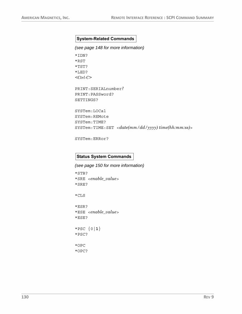
AMERICAN MAGNETICS, INC. REMOTE INTERFACE REFERENCE : SCPI COMMAND SUMMARY
(see page 148 for more information)
*IDN?*RST*TST?*LED?<Ctrl-C>
PRINT:SERIALnumber?PRINT:PASSword?SETTINGS?
SYSTem:LOCalSYSTem:REMoteSYSTem:TIME?SYSTem:TIME:SET <date(mm/dd/yyyy) time(hh:mm:ss)>
SYSTem:ERRor?
(see page 150 for more information)
*STB?*SRE <enable_value>*SRE?
*CLS
*ESR?*ESE <enable_value>*ESE?
*PSC {0|1}*PSC?
*OPC*OPC?
System-Related Commands
Status System Commands
130 REV 9

AMERICAN MAGNETICS, INC. REMOTE INTERFACE REFERENCE : SCPI COMMAND SUMMARY
(see page 152 for more information)
SUPPly:VOLTage:MINimum?SUPPly:VOLTage:MAXimum?
SUPPly:CURRent:MINimum?SUPPly:CURRent:MAXimum?
SUPPly:TYPE?SUPPly:MODE?
(see page 154 for more information)
CONFigure:STABility:MODE {0|1|2}CONFigure:STABility <percent>CONFigure:STABility:RESistor {0|1}CONFigure:COILconst <value (kG/A, T/A)>CONFigure:INDuctance <inductance (H)>CONFigure:ABsorber {0|1}
STABility:MODE?STABility?STABility:RESistor?COILconst?INDuctance:SENSe?INDuctance?ABsorber?
(see page 156 for more information)
CONFigure:PSwitch {0|1}CONFigure:PSwitch:CURRent <current (A)>CONFigure:PSwitch:TRANsition {0|1}CONFigure:PSwitch:HeatTIME <time (sec)>CONFigure:PSwitch:CoolTIME <time (sec)>CONFigure:PSwitch:PowerSupplyRampRate <rate (A/s)>CONFigure:PSwitch:CoolingGAIN <percent>
PSwitch:INSTalled?
Supply Setup Configuration Queries
Load Setup Configuration Commands and Queries
Switch Setup Configuration Commands and Queries
REV 9 131

AMERICAN MAGNETICS, INC. REMOTE INTERFACE REFERENCE : SCPI COMMAND SUMMARY
PSwitch:AUTODetect?PSwitch:CURRent?PSwitch:TRANsition?PSwitch:HeatTIME?PSwitch:CoolTIME?PSwitch:PowerSupplyRampRate?PSwitch:CoolingGAIN?
(see page 157 for more information)
CONFigure:CURRent:LIMit <current (A)>CONFigure:QUench:DETect {0|1|2|3}CONFigure:QUench:RATE {1|2|3|4|5}CONFigure:OPLimit:MODE {0|1|2}CONFigure:OPLimit:ICSLOPE <value (A/K)>
CONFigure:OPLimit:ICOFFSET <value (A)>CONFigure:OPLimit:TMAX <value (K)>CONFigure:OPLimit:TSCALE <value (K/V)>CONFigure:OPLimit:TOFFSET <value (K)>CONFigure:RAMPDown:ENABle {0|1}
CURRent:LIMit?QUench:DETect?QUench:RATE?OPLimit:IC?OPLimit:TEMP?OPLimit:MODE?OPLimit:ICSLOPE?OPLimit:ICOFFSET?OPLimit:TMAX?OPLimit:TSCALE?OPLimit:TOFFSET?RAMPDown:ENABle?
(see page 160 for more information)
CONFigure:RAMP:RATE:SEGments <value>CONFigure:RAMP:RATE:UNITS {0|1}CONFigure:FIELD:UNITS {0|1}
RAMP:RATE:SEGments?
Protection Setup Configuration Commands and Queries
Misc Setup Configuration Commands and Queries
132 REV 9

AMERICAN MAGNETICS, INC. REMOTE INTERFACE REFERENCE : SCPI COMMAND SUMMARY
RAMP:RATE:UNITS?FIELD:UNITS?
(see page 161 for more information)
CONFigure:LOCK:PSwitch:CONTRol {0|1}CONFigure:LOCK:TARGet {0|1}CONFigure:LOCK:RAMP-PAUSE {0|1}CONFigure:LOCK:ZEROfield {0|1}CONFigure:LOCK:RAMPrate {0|1}CONFigure:LOCK:SUPPly {0|1}CONFigure:LOCK:VOLTage:LIMit {0|1}CONFigure:LOCK:QUench:RESet {0|1}CONFigure:LOCK:INCR-DECR {0|1}CONFigure:LOCK:FIELD-CURRent {0|1}CONFigure:LOCK:FIELD:UNITS {0|1}CONFigure:LOCK:STABility {0|1}CONFigure:LOCK:INDuctance {0|1}CONFigure:LOCK:VOLTage:VS-VM {0|1}CONFigure:LOCK:VOLTMeter {0|1}CONFigure:LOCK:FINEadjust {0|1}CONFigure:LOCK:COILconst {0|1}CONFigure:LOCK:CURRent:LIMit {0|1}CONFigure:LOCK:CURRent:RATING {0:1}CONFigure:LOCK:PSwitch:SETtings {0|1}CONFigure:LOCK:QUench:DETect {0|1}CONFigure:LOCK:QUench:RATE {0|1}CONFigure:LOCK:ABsorber {0|1}CONFigure:LOCK:RAMPDown {0|1}CONFigure:LOCK:BRIGHTness {0|1}CONFigure:LOCK:NETsetup {0|1}CONFigure:LOCK:OPLimit {0|1}
(see page 161 for more information)
LOCK:PSwitch:CONTRol?LOCK:TARGet?LOCK:RAMP-PAUSE?LOCK:ZEROfield?LOCK:RAMPrate?LOCK:SUPPly?LOCK:VOLTage:LIMit?
Lock Configuration Commands
Lock Configuration Queries
REV 9 133

AMERICAN MAGNETICS, INC. REMOTE INTERFACE REFERENCE : SCPI COMMAND SUMMARY
LOCK:QUench:RESet?LOCK:INCR-DECR?LOCK:FIELD-CURRent?LOCK:FIELD:UNITS?LOCK:STABility?LOCK:INDuctance?LOCK:VOLTage:VS-VM?LOCK:VOLTMeter?LOCK:FINEadjust?LOCK:COILconst?LOCK:CURRent:LIMit?LOCK:CURRent:RATING?LOCK:PSwitch:SETtings?LOCK:QUench:DETect?LOCK:QUench:RATE?LOCK:ABsorber?LOCK:RAMPDown?LOCK:BRIGHTness?LOCK:NETsetup?LOCK:OPLimit?
(see page 167 for more information)
CONFigure:IPNAME <system name>
IPNAME?
(see page page 167 for more information)
CONFigure:VOLTage:LIMit <voltage (V)>CONFigure:CURRent:TARGet <current (A)>CONFigure:FIELD:TARGet <field (kG, T)>CONFigure:RAMP:RATE:CURRent <segment>,<rate (A/s, A/min)>,<upper bound (A)>CONFigure:RAMP:RATE:FIELD <segment>,<rate (kG/s, kG/min, T/s, T/min)>,<upper bound (kG, T)>
VOLTage:LIMit?CURRent:TARGet?FIELD:TARGet?RAMP:RATE:CURRent:<segment>?RAMP:RATE:FIELD:<segment>?
Net Setup Configuration Commands and Queries
Ramp Target/Rate Configuration Commands and Queries
134 REV 9

AMERICAN MAGNETICS, INC. REMOTE INTERFACE REFERENCE : SCPI COMMAND SUMMARY
(see page 169 for more information)
VOLTage:MAGnet?VOLTage:SUPPly?CURRent:MAGnet?CURRent:SUPPly?FIELD:MAGnet?
(see page 170 for more information)
RAMPPAUSEINCRDECRZERO
STATE?
(see page 171 for more information)
PSwitch {0|1}PSwitch?PERSistent?
(see page 172 for more information)
QUench {0|1}QUench?
Quench:COUNT?QUenchFile?QUenchBackup?
(see page 173 for more information)
CONFigure:RAMPDown:RATE:SEGments <value>
Measurement Commands and Queries
Ramping State Commands and Queries
Switch Heater Commands and Queries
Quench State Commands and Queries
Rampdown State Commands and Queries
REV 9 135

AMERICAN MAGNETICS, INC. REMOTE INTERFACE REFERENCE : SCPI COMMAND SUMMARY
CONFigure:RAMPDown:RATE:CURRent <segment>,<rate (A/s, A/min)>,<upper bound (A)>CONFigure:RAMPDown:RATE:FIELD <segment>,<rate (kG/s, kG/min, T/s, T/min)>, <upper bound (Kg, T)>
RAMPDown:RATE:SEGments?RAMPDown:RATE:CURRent:<segment>?RAMPDown:RATE:FIELD:<segment>?
RAMPDown:COUNT?RAMPDownFile?RAMPDownBackup?
(see page 176 for more information)
*ETE <enable_value>*ETE?*TRG
(these commands act as remote keypresses on any interface/port, seethe table on page 146)
W_KEYSTRING_SHIFTW_KEYSTRING_TARGETW_KEYSTRING_ZEROFIELDW_KEYSTRING_PERSISTENTW_KEYSTRING_RAMPPAUSEW_KEYSTRING_1W_KEYSTRING_2W_KEYSTRING_3W_KEYSTRING_4W_KEYSTRING_5W_KEYSTRING_6W_KEYSTRING_7W_KEYSTRING_8W_KEYSTRING_9W_KEYSTRING_0W_KEYSTRING_PERIODW_KEYSTRING_PLUSMINUSW_KEYSTRING_ESCW_KEYSTRING_MENUW_KEYSTRING_RIGHT
Trigger Control and Queries
Keypress Commands
136 REV 9

AMERICAN MAGNETICS, INC. REMOTE INTERFACE REFERENCE : PROGRAMMING OVERVIEW
W_KEYSTRING_LEFTW_KEYSTRING_ENTERW_FINE_ADJ_DELTA <value>
PROGRAMMING OVERVIEW
The Model 430 Programmer conforms to the SCPI (StandardCommands for Programmable Instruments) IEEE standard. The SCPIstandard is an ASCII-based specification designed to provide aconsistent command structure for instruments from variousmanufacturers.
The Model 430 Programmer also implements a status system formonitoring the state of the Model 430 through the Standard Event andStatus Byte registers.
SCPI LANGUAGE INTRODUCTION
SCPI commands conform to a tree structure where commands aregrouped according to common keywords. For example, commandswhich set a Model 430 Programmer setup or operating parameter beginwith the keyword CONFigure. The keywords are shown in upper caseand lower case to indicate acceptable abbreviations. For the examplekeyword CONFigure, the user may send either the abbreviated form ofCONF, or the entire keyword CONFIGURE. Any other form of the keywordis illegal and will generate an error.
Many commands also require multiple keywords to traverse the treestructure of the entire Model 430 Programmer command set. Forexample, commands associated with a current setting require the prefixof CONFigure:CURRent. Note that a colon ( : ) separates thekeywords. No spaces are allowed before or after the colon. Parametersmust be separated from the command keyword(s) by at least one space.
SCPI STATUS SYSTEM The Model 430 Programmer status system reports various conditions ofthe instrument in two registers groups shown in the figure below. Theregister groups consist of a condition or event register, and an enableregister which controls the actions of specific bits within the condition orevent registers
A condition register continuously monitors the state of the instrument.The bits of a condition register are updated in real time. A conditionregister is read-only and is not cleared when you read the register. Aquery of a condition register returns a decimal value in the appropriateoutput buffer which corresponds to the binary-weighted sum of all bitsset in the register.
REV 9 137

AMERICAN MAGNETICS, INC. REMOTE INTERFACE REFERENCE : PROGRAMMING OVERVIEW
An event register latches various events. Events are not buffered,therefore once a bit is set in the event register, further occurrences ofthat event are ignored. Once a bit is set in an event register, the bitremains set until the register is read (*ESR?) or a *CLS (clear status)command is issued. A query of an event register returns a decimal valuein the appropriate output buffer which corresponds to the binary-weighted sum of all bits set in the register.
An enable register (or bitmask) defines which bits in an event registerare reported to the Status Byte register group. An enable register can beboth written and queried. The *CLS (clear status) command does notclear an enable register. To enable or disable bits in an enable register,write a decimal value which corresponds to the binary-weighted sum ofthe bits you wish reported to the Status Byte register.
value
value
The Model 430 Programmer Status System
138 REV 9

AMERICAN MAGNETICS, INC. REMOTE INTERFACE REFERENCE : PROGRAMMING OVERVIEW
STATUS BYTE REGISTER The Status Byte register group reports conditions from the StandardEvent register or output buffers. Data in the output buffer is immediatelyreported in the “Serial Message Available” bit (bit 3). Clearing a bit in theStandard Event register will update the corresponding bit in the StatusByte register, according to the Standard Event enable register. Readingthe pending messages in the output buffers will clear the appropriate“Message Available” bit. The bit definitions for the Status Byte registerare defined in the following table:
Bit 2 of the Status Byte register, indicating a quench condition, remainsset until the quench condition is cleared via the front panel or by remotecommand. Bits 3 and 4 remain set until all data has been read from therespective output buffer.
The Status Byte condition register is cleared when:
• A *CLS command is executed.• The Standard Event register is read (only bit 5 of the Status Byte register is
cleared).• The indicated condition no longer exists.• The power is turned off and then back on.
The Status Byte enable register is cleared when:
• The *SRE 0 command is executed.• The power is turned off and then back on, and the Model 430 Programmer
was configured for *PSC 1 (power-on status clear). The enable register set-
Bit Definitions for the Status Byte Register
Bit NumberDecimal
Value Definition
0 Not Used 1 Always “0”.
1 External Rampdown 2 An external rampdown is active.
2 Quench Condition 4 The Model 430 has detected a quench.
3 Serial Message Avail-able
8 The serial output buffer contains unread data.
4 Not Used 16 Always “0”.
5 Standard Event 32 One or more enabled bits are set in the Standard Event register.
6 Status Byte Summary 64 One or more enabled bits are set in the Status Byte register.
7 Not Used 128 Always “0”.
REV 9 139

AMERICAN MAGNETICS, INC. REMOTE INTERFACE REFERENCE : PROGRAMMING OVERVIEW
ting is persistent if the Model 430 Programmer is configured for *PSC 0 (no status clear on power-on).
READING THE STATUS BYTE USING *STB?The *STB? returns the contents of the Status Byte register, but itis processed in the command queue like any other command.The *STB? command does not clear bit 6 of the Status Byteregister.
USING THE MESSAGE AVAILABLE BIT(S)The “Message Available” bits (bits 3 or 4) of the Status Byteregister can be used to determine when data is available to readinto your host computer. The Model 430 Programmer clears the“Message Available” bits only after all data has been read fromthe output buffer(s).
The “Message Available” bits of the Status Byte register areuseful for determining if queries have executed; however, theyare not useful alone for determining if commands havecompleted execution, since commands do not provide returndata.
STANDARD EVENT REGISTER
The Standard Event register group reports a power-on condition, variouserror conditions, and indicates when an operation has completed. Any orall of the Standard Events can be reported to the Status Byte register byenabling the corresponding bit(s) in the Standard Event enable register(see the figure on page 138). To set the Standard Event enable register,write a binary-weighted decimal value using the *ESE <value>command.
The bit definitions for the Standard Event register are provided in thetable on the following page. To query the Model 430 Programmer for thedetails of a reported error in the Standard Event register, use theSYSTem:ERRor? query. See page 178 for a complete discussion of theerror buffer and messages.
The Standard Event register is cleared when:
• The *CLS (clear status) command is executed.• The Standard Event register is queried using the *ESR? command.• The power is turned off and then back on.
The Standard Event enable register is cleared when:
• The *ESE 0 command is executed.• The power is turned off and then back on, and the Model 430 Programmer
was configured for *PSC 1 (power-on status clear). The enable register set-
140 REV 9

AMERICAN MAGNETICS, INC. REMOTE INTERFACE REFERENCE : PROGRAMMING OVERVIEW
ting is persistent if the Model 430 Programmer is configured for *PSC 0 (no status clear on power-on).
COMMAND HANDSHAKING
The Model 430 Programmer provides an internal command queue thatcan store up to 4 commands or queries. However, it is possible that thehost computer can overwhelm the command queue by sendingcommands faster than the Model 430 can execute. If the Model 430Programmer cannot process a command due to a full command queue,the command is ignored and the -303,”Input overflow” error isreported.
Handshaking is generally not a concern unless more than 4 commandsare sent sequentially. If a query is sent, the user will normally wait forreturn data for the queries before proceeding to send the next query orcommand. In the case of sending numerous commands in sequence,there are two methods available to help prevent command queueoverflows which are discussed below.
USING THE *OPC COMMAND
The *OPC command is executed within the normal commandqueue. Upon completed execution of the *OPC command, the“Operation Complete” bit (bit 0) of the Standard Event register willbe set. This command is useful should many commands be sentto the Model 430 Programmer in rapid succession.
Bit Definitions for the Standard Event Register
Bit NumberDecimal
Value Definition
0 Operation Complete 1 All commands prior to and including *OPC have been executed.
1 Not Used 2 Always “0”.
2 Query Error 4 A query error occurred. See the error messages in the -200 range.
3 Device Error 8 A device error occurred. See the error messages in the -400 range.
4 Execution Error 16 An execution error occurred. See the error messages in the -300 range.
5 Command Error 32 A command error occurred. See the error messages in the -100 range.
6 Not Used 64 Always “0”.
7 Power On 128 Power has been cycled since the last time the Standard Event register was read or cleared.
REV 9 141

AMERICAN MAGNETICS, INC. REMOTE INTERFACE REFERENCE : PROGRAMMING OVERVIEW
NOTE The *OPC command historically is designed to generate an SRQ which can be monitored by a serial poll over a GPIB interface, which operates outside of the normal command queue. Since a GPIB interface is not available in the Model 430, the *OPC command has limited value (as it would require polling the status registers using the command queue) and should be ignored in favor of the *OPC? query documented below for the serial and Ethernet interfaces.
USING THE *OPC? QUERY
The *OPC? query is similar to the *OPC command, but instead ofsetting the “Operation Complete” bit of the Standard Eventregister, the *OPC? query returns a “1” (plus terminationcharacters) to the appropriate output buffer when executed.
Using *OPC? is a simple solution for determining completedremote command execution (because commands do not send areply). It is also unambiguous during simultaneous serial andEthernet operation since the result is returned directly to therequesting communication interface.
An example of a sequence of commands using the *OPC? queryto handshake is the following:
CONF:CURR:TARG 50.0;CONF:RAMP:RATE:CURR 1,0.1,80.0;CONF:VOLT:LIM 5.0;*OPC?;
The above example sets the target current to 50.0 A, the ramprate segment #1 to 0.1 A/s up to 80.0 A, the voltage limit to 5.0 V,and sends as the fourth command the *OPC? query fordetermining when execution all of the commands (including*OPC?) is completed. The *OPC? query will return a “1” to therequesting interface when it executes.
142 REV 9

AMERICAN MAGNETICS, INC. REMOTE INTERFACE REFERENCE : RS-232 CONFIGURATION
RS-232 CONFIGURATION
The Model 430 Programmer uses the following fixed parameters relatedto the RS-232 interface:
• Baud Rate: 115200• Parity: No Parity• Data Bits: 8 Data Bits• Number of Start Bits: 1 bit• Number of Stop Bits: 1 bit• Flow Control: Hardware (RTS/CTS)
SERIAL CONNECTOR An IBM-compatible computer’s serial port can be directly connected tothe Model 430 Programmer via a standard DB9-female-to-DB9-femalenull modem serial cable. Refer to your computer’s documentation todetermine which serial ports are available on your computer and therequired connector type.
The Model 430 Programmer is classified as a DTE (Data TerminalEquipment) device. It uses the standard DB9 male connector andidentical pinout used on IBM-compatible computers. The RS-232connector pinout for the Model 430 Programmer is fully documented onpage 204 in the Appendix.
TERMINATION CHARACTERS
All commands and queries are transmitted and received as ASCII valuesand are case insensitive. The Model 430 Programmer always transmits<CR><LF> (a carriage return followed by a linefeed) at the end of anRS-232 transmission. The Model 430 Programmer can accept <CR>,<LF>, <CR><LF>, or <LF><CR>, or a semicolon ( ; ) as terminationcharacters from an external computer.
ETHERNET CONFIGURATION
The Model 430 Programmer provides a 10/100Base-T Ethernet interfaceas a standard feature. It complies with the IEEE 802.3u 100Base-TX and802.3 10Base-T standards.
The Model 430 Programmer allows its IP address, subnet mask andgateway IP address to be assigned either statically or dynamically. Tomake these values static and assign them manually, set IP AddressAssignment to Static (see page 106) and then set the values using the
REV 9 143

AMERICAN MAGNETICS, INC. REMOTE INTERFACE REFERENCE : ETHERNET CONFIGURATION
MS 0
parameters under the Net Setup submenu (beginning on page 107). Tomake the values dynamically assigned by a network DHCP server, set IPAddress Assignment to DHCP.
The system name (also known as host name or computer name), can beset using remote communications (either Ethernet or RS-232); it cannotbe edited using the front panel keypad.
All network parameters (even those assigned by a DHCP server) can beviewed using the Net Settings submenu (see page 104).
ETHERNET CONNECTOR The Model 430 Programmer uses a standard RJ-45 jack for Ethernetcommunications. The Ethernet jack pinout is fully documented onpage 203 in the Appendix.
TERMINATION CHARACTERS
All commands and queries are transmitted and received as ASCII valuesand are case insensitive. The Model 430 Programmer always transmits<CR><LF> (a carriage return followed by a linefeed) at the end of anEthernet transmission. The Model 430 can accept <CR>, <LF>,<CR><LF>, or <LF><CR>, or a semicolon ( ; ) as termination charactersfrom an external computer.
PORT ASSIGNMENTS The Model 430 accepts connections to ports 23 and 7180. Port 7180 isrecommended for general command/query operation. When aconnection is successfully established to the Model 430, the following“hello” message is immediately returned:
American Magnetics Model 430 IP Interface\r\nHello.\r\n
Multiple connections to port 7180 are allowed. Multiple connections toport 23 are also allowed, but the special broadcast protocol described inthe following section will only occur for the last connection made to port23.
TELNET PORT 23 BROADCAST PROTOCOL
Port 23 has a special function in that the display characters arebroadcast each time the display is internally updated by the Model 430.This occurs approximately every 250 milliseconds. This feature isintended to allow the user to optionally show a remote display thatremains synced with the front panel display.
The broadcast message format will be as the following example output(terminated with a <CR><LF> pair):
G_DISP_UPDATE:: +50.00 A - Mode: Holding :: 0.00 Vm PSwitch Heater: ON ::0::1::0::1::0::
144 REV 9

AMERICAN MAGNETICS, INC. REMOTE INTERFACE REFERENCE : ETHERNET CONFIGURATION
The MSG_DISP_UPDATE:: is the delimiter text indicating the displaytext follows. The first line of the display is the text up to the next ::delimiter pair, followed by the second line of the display up to the next ::pair.
The state (0=OFF, 1=ON) of each front panel LED then follows delimitedby :: pairs. The LED field order is: SHIFT, FIELD AT TARGET,MAGNET IN PERSISTENT MODE, CURRENT LEADS ENERGIZED,and MAGNET QUENCH.
Therefore, the example broadcasted output above would decode to adisplay as follows:
with the FIELD AT TARGET and CURRENT LEADS ENERGIZEDLEDs in the ON state.
If the display is in the voltmeter mode (see page 69) for either Vs or Vm,the broadcasted message format changes to the following exampleoutput (terminated with a <CR><LF> pair):
The MSG_VOLTMETER_UPDATE:: is the delimiter text indicating thevoltmeter display information follows. The field/current, status indication,and voltage displays are shown first, followed by the delimited LEDstates in the exact same order as described above. Then the displayedvoltage value name is provided followed by the final :: pair and theactual voltage value in volts.
Therefore, the example broadcasted voltmeter output above woulddecode to a display as follows:
with no LEDs in the ON state.
CUSTOM DISPLAY CHARACTERS
Please note that the ramping character and certain other displaycharacters have custom-defined codes beyond 0x7F that do notmap directly to ASCII equivalents. The custom character and the
+50.00 A - Mode: Holding0.00 Vm PSwitch Heater: ON
MSG_VOLTMETER_UPDATE:: +50.00 A - :: +2.50 Vm ::0::0::0::0::0::0::Vm::2.500000
+50.00 A — -10 0Vm +10+2.50 Vm |''''|''''|''|'''''|
REV 9 145

AMERICAN MAGNETICS, INC. REMOTE INTERFACE REFERENCE : ETHERNET CONFIGURATION
actual byte value that is sent in a broadcast message are shownin the table below:
BROADCASTED KEYPRESSES AND EVENTS
In addition to the broadcasted display message, there areadditional broadcast messages related to physical keypresses(via the front panel) and certain events that will be interleaved asthey occur with the broadcasted display messages. Each isterminated on transmission with the <CR><LF> pair. Themessages are described in the table below:
Broadcasted Custom Display Characters
Character Byte Value Character Byte Value
P 0x80 0x86
0x81 0x87
0x82 V 0x88
0x83 C 0x89
0x84 T 0x8A
0x85
Broadcasted Keypress and Event Messages
Message (ASCII format) Meaning
MSG_KEY_SHIFT SHIFT key pressed
MSG_KEY_TARGET TARGET FIELD SETPOINT key pressed
MSG_KEY_ZEROFIELD RAMP TO ZERO key pressed
MSG_KEY_PERSISTENT PERSIST. SWITCH CONTROL key pressed
MSG_KEY_RAMPPAUSE RAMP/PAUSE key pressed
MSG_KEY_1 1 key pressed
MSG_KEY_2 2 key pressed
MSG_KEY_3 3 key pressed
MSG_KEY_4 4 key pressed
MSG_KEY_5 5 key pressed
MSG_KEY_6 6 key pressed
MSG_KEY_7 7 key pressed
MSG_KEY_8 8 key pressed
146 REV 9

AMERICAN MAGNETICS, INC. REMOTE INTERFACE REFERENCE : ETHERNET CONFIGURATION
MSG_KEY_9 9 key pressed
MSG_KEY_0 0 key pressed
MSG_KEY_PERIOD . key pressed
MSG_KEY_PLUSMINUS +/- key pressed
MSG_KEY_ESC ESC key pressed
MSG_KEY_MENU MENU key pressed
MSG_KEY_RIGHT Right arrow key pressed
MSG_KEY_LEFT Left arrow key pressed
MSG_KEY_ENTER ENTER key pressed
MSG_BEEP Audible beep emitted
MSG_EXT_RAMPDOWN_START External rampdown activated
MSG_EXT_RAMPDOWN_END External rampdown ended
MSG_FINE_ADJ_DELTA <value> Encoder adjust delta (value sent is a positive or neg-ative integer of the number of encoder clicks, user must convert to a meaningful delta for a given parameter being edited).
Broadcasted Keypress and Event Messages (Continued)
Message (ASCII format) Meaning
REV 9 147

AMERICAN MAGNETICS, INC. REMOTE INTERFACE REFERENCE : COMMAND REFERENCE
COMMAND REFERENCE
The following paragraphs present all Model 430 Programmer commandsand queries in related groups and a detailed description of the function ofeach command or query is provided. Examples are also provided whereappropriate. Return strings may be up to 80 characters in length.
SYSTEM-RELATED COMMANDS
• *IDN?
Returns the identification string of the Model 430 Programmer. Theidentification string contains the manufacturer name, model number,serial number, and firmware revision code. Example output:
AMERICAN MAGNETICS INC.,MODEL 430,1215001,3.00
• *RST
Resets the Model 430 Programmer. This is equivalent to cycling thepower to the Model 430 Programmer using the power switch. All non-volatile calibration data and battery-backed memory is restored. Status iscleared according to the *PSC setting.
• *TST?
Performs a self-test. Currently always returns “1”.
• *LED?
Returns a comma-delimited list of the LED states with 0=OFF and1=ON. The LED field order is: SHIFT, FIELD AT TARGET, MAGNET INPERSISTENT MODE, CURRENT LEADS ENERGIZED, and MAGNETQUENCH. For example, the transaction:
Sent: *LED?Returned: 0,1,0,1,0
indicates the FIELD AT TARGET and CURRENT LEADS ENERGIZEDLEDs are engergized.
• <Ctrl-C>
This clears the output buffers of the Model 430 Programmer andprepares the instrument for a new command. Status registers areunaffected. <Ctrl-C> corresponds to ASCII code 03.
148 REV 9

AMERICAN MAGNETICS, INC. REMOTE INTERFACE REFERENCE : COMMAND REFERENCE
• PRINT:SERIALnumber?
Returns the serial number.
• PRINT:PASSword?
Returns the presently set numerical password.
• SETTINGS?
Returns a multi-line ASCII text dump of all the Model 430 settings. Theoutput of this query is terminated with two contiguous pairs of<CR><LF> characters (i.e. double terminators).
• SYSTem:LOCal
Enables all front panel controls. All front panels controls are enabled bydefault after a power-up or *RST command.
• SYSTem:REMote
NOTE The SYSTem:REMote command only disables the front panel controls for purposes of preventing accidental operation of a front panel feature. It is not necessary for this command to be sent prior to using a remote interface. Send the SYSTem:LOCal command, send the *RST command, press SHIFT followed by MENU, or cycle Model 430 Programmer power to re-enable the front panel controls.
Disables all front panel controls. If the Model 430 Programmer is in theremote mode, an asterisk ( * ) will appear in the front panel display inthe position just below the ramping character as shown below.
• SYSTem:TIME?
Returns the date and time of the Model 430 Programmer in the formatmm/dd/yyyy hh:mm:ss. Time is always reported in 24-hour format.Example output: 05/02/2017 21:13:50
• SYSTem:TIME:SET <date(mm/dd/yyyy) time(hh:mm:ss)>
Sets the date and time of the Model 430 Programmer using the formatmm/dd/yyyy hh:mm:ss. Time is always set in 24-hour format.
+50.00 kG ¡ Mode: Ramping +1.50 Vs * PSwitch Heater: ON
^
Asterisk Indicating the Model 430 is in Remote Mode
REV 9 149

AMERICAN MAGNETICS, INC. REMOTE INTERFACE REFERENCE : COMMAND REFERENCE
• SYSTem:ERRor?
Queries the error buffer of the Model 430 Programmer. Up to 10 errorsare stored in the error buffer. Errors are retrieved in first-in-first-out(FIFO) order. The error buffer is cleared by the *CLS (clear status)command or when the power is cycled. Errors are also cleared as theyare read. See page 178 for a complete description of the error buffer andmessages.
STATUS SYSTEM COMMANDS
The status system register groups and commands are illustrated thefigure on page 138.
• *STB?
Returns the contents of the Status Byte register. The *STB? commanddoes not clear the “Summary Bit” (bit 6) of the Status Byte register.
• *SRE <enable_value>
Enables bits in the Status Byte register to be reported in the “SummaryBit” (bit 6) of the Status Byte register. To enable bits, you must write adecimal <enable_value> which corresponds to the binary-weighted sumof the bits you wish to enable. Refer to page 139 for more information.For example, to enable quench detections only in the “Summary Bit” ofthe Status Byte register, send the command: *SRE 4.
• *SRE?
The *SRE? query returns a decimal sum which corresponds to thebinary-weighted sum of the bits enabled by the last *SRE command.
• *CLS
Clears the Standard Event register and the error buffer.
• *ESR?
Returns a decimal sum which corresponds to the binary-weighted sumof the contents of the Standard Event register.
• *ESE <enable_value>
Enables bits in the Standard Event register to be reported in the“Standard Event” bit (bit 5) of the Status Byte register. To enable bits, youmust write a decimal <enable_value> which corresponds to the binary-weighted sum of the bits you wish to enable. Refer to page 141 for more
150 REV 9

AMERICAN MAGNETICS, INC. REMOTE INTERFACE REFERENCE : COMMAND REFERENCE
information. For example, to enable all categories of error messages tobe reported in bit 5 of the Status Byte register, send: *ESE 60.
• *ESE?
The *ESE? query returns a decimal sum which corresponds to thebinary-weighted sum of the bits enabled by the last *ESE command.
• *PSC {0|1}
Power-On Status Clear. If *PSC 1 is in effect, the Standard Event enableregister and the Status Byte enable register are cleared at power on. If*PSC 0 is in effect, the enable registers are not cleared at power on.The default setting is “1”.
• *PSC?
Returns the Power-On Status Clear setting currently in effect. A value of“0” indicates the enable registers are not cleared at power on; a value of“1” indicates the enable registers are cleared at power on.
• *OPC
Sets the “Operation Complete” bit (bit 0) of the Standard Event registerwhen executed. See page 141 for a complete discussion.
• *OPC?
Returns “1” to the requesting interface when executed. See page 142 formore information.
REV 9 151
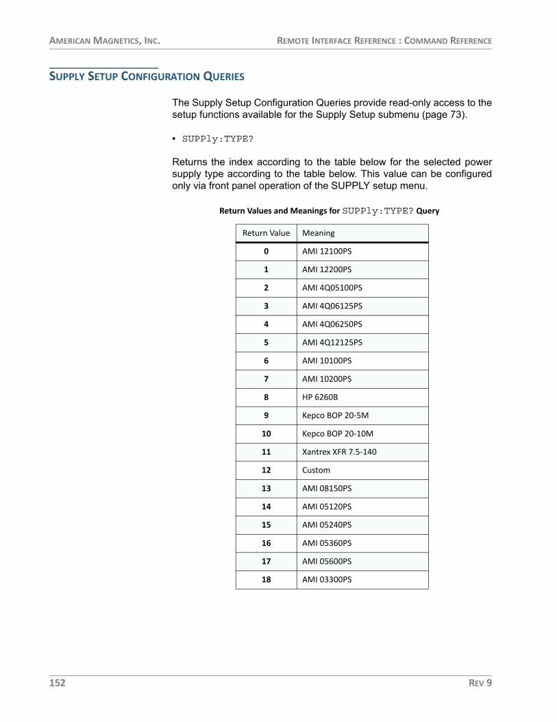
AMERICAN MAGNETICS, INC. REMOTE INTERFACE REFERENCE : COMMAND REFERENCE
SUPPLY SETUP CONFIGURATION QUERIES
The Supply Setup Configuration Queries provide read-only access to thesetup functions available for the Supply Setup submenu (page 73).
• SUPPly:TYPE?
Returns the index according to the table below for the selected powersupply type according to the table below. This value can be configuredonly via front panel operation of the SUPPLY setup menu.
Return Values and Meanings for SUPPly:TYPE? Query
Return Value Meaning
0 AMI 12100PS
1 AMI 12200PS
2 AMI 4Q05100PS
3 AMI 4Q06125PS
4 AMI 4Q06250PS
5 AMI 4Q12125PS
6 AMI 10100PS
7 AMI 10200PS
8 HP 6260B
9 Kepco BOP 20-5M
10 Kepco BOP 20-10M
11 Xantrex XFR 7.5-140
12 Custom
13 AMI 08150PS
14 AMI 05120PS
15 AMI 05240PS
16 AMI 05360PS
17 AMI 05600PS
18 AMI 03300PS
152 REV 9

AMERICAN MAGNETICS, INC. REMOTE INTERFACE REFERENCE : COMMAND REFERENCE
• SUPPly:VOLTage:MINimum?
Returns the minimum power supply compliance setting in volts. Thisvalue can be configured only via front panel operation using the Supplysubmenu and is set automatically when a preset supply type is selected.
• SUPPly:VOLTage:MAXimum?
Returns the maximum power supply compliance in volts. This value canbe configured only via front panel operation using the Supply submenuand is set automatically when a preset supply type is selected.
• SUPPly:CURRent:MINimum?
Returns the minimum output current capacity of the power supply inamperes. This value can be configured only via front panel operationusing the Supply submenu and is set automatically when a preset supplytype is selected.
• SUPPly:CURRent:MAXimum?
Returns the maximum output current capacity of the power supply inamperes. This value can be configured only via front panel operationusing the Supply submenu and is set automatically when a preset supplytype is selected.
• SUPPly:MODE?
Returns an integer value corresponding to the voltage output modeaccording to the table below:
This value can be configured only via front panel operation using theSupply submenu and is set automatically when a preset supply type isselected.
Return Values and Meanings for SUPPly:MODE? Query
Return Value Meaning
0 +0.000 to +5.000
1 +0.000 to +10.000
2 -5.000 to +5.000
3 -10.000 to +10.000
4 -5.000 to +0.000
5 +0.000 to +8.000
REV 9 153

AMERICAN MAGNETICS, INC. REMOTE INTERFACE REFERENCE : COMMAND REFERENCE
LOAD SETUP CONFIGURATION COMMANDS AND QUERIES
The Load Setup Configuration Commands and Queries provide read/write access to the setup functions available for the Load Setupsubmenu (page 78).
• CONFigure:STABility:MODE {0|1|2}
“0” configures the stability mode as “Auto”, “1” is “Manual”, and “2” is“Test”. If “Auto” mode is selected and an inductance value is notspecified (i.e. the inductance entry is zero), the Model 430 will beeponce, generate an error, and revert to “Manual” stability mode. Manualmode is the default value.
In “Auto” stability mode, the stability setting is automatically adjust perthe presence or absence of a persistent switch, the presence or absenceof a stabilizing resistor, and the estimated or measured magnetinductance.
• STABility:MODE?
Returns “0” for “Auto” stability mode, “1” for “Manual”, and “2” for “Test”.
• CONFigure:STABility <percent>
Sets the stability setting in percent. Valid range is 0.0 to 100.0%.
• STABility?
Returns the stability setting in percent.
• CONFigure:STABility:RESistor {0|1}
An argument of “0” specifies no stabilizing resistor is installed. “1”indicates a stabilizing resistor is installed. “0” is the default value.
• STABility:RESistor?
Returns “0” for no stabilizing resistor and “1” for an installed stabilizingresistor.
• CONFigure:COILconst <value (kG/A, T/A)>
Sets the coil constant (also referred to as the field-to-current ratio) perthe selected field units. The coil constant must be set to a non-zero,positive value in order to command or query the Model 430 Programmerin units of field.
154 REV 9

AMERICAN MAGNETICS, INC. REMOTE INTERFACE REFERENCE : COMMAND REFERENCE
• COILconst?
Returns the coil constant setting in kG/A or T/A per the selected fieldunits.
• CONFigure:INDuctance <inductance (H)>
Sets the currently-connected magnet inductance in Henries.
• INDuctance:SENSe?
Initiates a direct measurement of the currently connected magnet. Themeasurement requires the magnet to be ramping up or down while notpassing through a ramp segment change during the measurement. Ifthese conditions are not met, the Model 430 will beep once, generate anerror, and exit the measurement. Otherwise, this will return ameasurement of the magnet inductance in Henries. The measured valuewill automatically be stored as the currently-connected inductance.
NOTE The inductance measurement requires the magnet voltage input to the rear panel Magnet Station connector as described on page 193. Please note that some magnet system manufacturers do not provide magnet voltage taps.
NOTE This remote command blocks communication for several seconds on all ports until the measurement process completes or is interrupted.
• INDuctance?
Returns the currently-connected magnet inductance in Henries.
• CONFigure:ABsorber {0|1}
Sending “0” indicates that an energy absorber is not present in thesystem. A “1” indicates that an energy absorber is present. “0” is thedefault value.
• ABsorber?
Returns “0” indicating that an energy absorber is not present in thesystem, or “1” indicating that an energy absorber is present.
REV 9 155

AMERICAN MAGNETICS, INC. REMOTE INTERFACE REFERENCE : COMMAND REFERENCE
SWITCH SETUP CONFIGURATION COMMANDS AND QUERIES
The Switch Setup Configuration Commands and Queries provide read/write access to the setup functions available for the Switch Setupsubmenu (page 83).
• CONFigure:PSwitch {0|1}
• PSwitch:INSTalled?
“0” indicates that a persistent switch is not installed on the connectedsuperconducting magnet. “1” indicates that a persistent switch isinstalled. The default value is “1”. If a persistent switch is installed, thepersistent switch heated current should be specified. Heating/coolingtimes should also be specified for timer-based switch transitions.
• CONFigure:PSwitch:CURRent <current (mA)>
Sets the persistent switch heater current in mA.
• PSwitch:CURRent?
Returns the persistent switch heater current setting in mA.
• PSwitch:AUTODetect?
Executes the auto-detection algorithm (refer to page 84) and returns theappropriate persistent switch heater current in mA. Note that after thisvalue is returned, it can be entered into the Model 430 Programmerusing the CONFigure:PSwitch:CURRent command.
NOTE This remote command blocks communication on all ports until the auto-detection process completes or is interrupted.
• CONFigure:PSwitch:TRANsition {0|1}
Sending a value of “0” selects the timer-based switch transitiondetection. Sending “1” selects the magnet voltage-based transitiondetection. Timer-based transition detection is the default.
• PSwitch:TRANsition?
“0” return value indicates timer-based switch transitions. “1” indicatesmagnet voltage-based transitions.
• CONFigure:PSwitch:HeatTIME <time (sec)>
Sets the time required in seconds for the persistent switch to becomeresistive after the persistent switch heater has been activated.
156 REV 9

AMERICAN MAGNETICS, INC. REMOTE INTERFACE REFERENCE : COMMAND REFERENCE
• PSwitch:HeatTIME?
Returns the persistent switch heated time in seconds.
• CONFigure:PSwitch:CoolTIME <time (sec)>
Sets the time required in seconds for the persistent switch to becomesuperconducting after the persistent switch heater has been deactivated.
• PSwitch:CoolTIME?
Returns the persistent switch cooled time in seconds.
• CONFigure:PSwitch:PowerSupplyRampRate <rate (A/s)>
Sets the ramp rate that will be used by the power supply to ramp thecurrent1 during the PERSIST. SWITCH CONTROL operation when theswitch is in a cooled state. This ramp rate can be much higher than whenthe switch is heated and the magnet is in the circuit. For moreinformation as to how this function operates, refer to page 58.
• PSwitch:PowerSupplyRampRate?
Returns the power supply ramp rate used to change the power supplyoutput when the magnet persistent switch is cool. The units are A/sec.
• CONFigure:PSwitch:CoolingGAIN <percent>
Sets the persistent switch cooling gain in percent.
• PSwitch:CoolingGAIN?
Returns the persistent switch cooling gain in percent.
PROTECTION SETUP CONFIGURATION COMMANDS AND QUERIES
The Protection Setup Configuration Commands and Queries provideread/write access to the setup functions available for the ProtectionSetup submenu (page 88).
• CONFigure:CURRent:LIMit <current (A)>
Sets the Current Limit in amperes. The Current Limit is the largestmagnitude operating current allowed during any ramping mode. For four-quadrant power supplies, the Current Limit functions as both a positiveand negative current limit. This value is typically provided by the magnet
1. While the magnet is in persistent mode.
REV 9 157

AMERICAN MAGNETICS, INC. REMOTE INTERFACE REFERENCE : COMMAND REFERENCE
manufacturer as the maximum safe limit of magnet operation (for AMImagnets it is the Magnet Rated Current, see page 108).
• CURRent:LIMit?
Returns the Current Limit in amperes.
• CONFigure:QUench:DETect {0|1|2|3}
Sending “0” disables the automatic quench detection function of theModel 430 Programmer. “1” enables the current-mismatch quenchdetection function of the Model 430. “2” enables the temperature-limitquench detection function. “3” enables both the current-mismatch andtemperature-limit methods of quench detection with either able to triggera quench. See page 123 for more information. “1” is the default value.
• QUench:DETect?
Returns “0” indicating automatic quench detection is disabled, or “1”indicating that the current-mismatch automatic quench detection isenabled. “2” indicates temperature-limit quench detection is enabled. “3”indicates both current-mismatch and temperature-limit quench detectionmethods are enabled.
• CONFigure:QUench:RATE {1|2|3|4|5}
Sets the value of the quench detect sensitivity. The range is from 1 to 5in integer increments. “1” indicates the most sensitivity. “5” is the leastsensitivity. “3” (normal) is the default value.
• QUench:RATE?
Returns the value of the quench detect sensitivity from 1 to 5 in integerincrements where “1” is the most sensitivity and “5” is the least.
• OPLimit:IC?
Returns the present value of the temperature-based maximum (i.e.critical) current limit, Ic, specified by the equation documented onpage 91.
• OPLimit:TEMP?
Returns the temperature in units of Kelvin read from the Auxiliary Input 3(see page 202).
• CONFigure:OPLimit:MODE {0|1|2}
Sets the Protection Mode for the Operational Limits submenu (refer tosection on page 91). Sending “0” sets the mode is Off. Sending “1” sets
158 REV 9
AMERICAN MAGNETICS, INC. REMOTE INTERFACE REFERENCE : COMMAND REFERENCE
the mode to “On Entry”. Sending “2” sets the mode to “Cont f(T)”. “0” isthe default value.
• OPLimit:MODE?
Returns “0” indicating the Protection Mode for the Operational Limitssubmenu is Off. Returns “1” indicating the mode is “On Entry”. Returns“2” indicating the mode is “Cont f(T)”.
• CONFigure:OPLimit:ICSLOPE <value (A/K)>
Sets the Ic Slope value in the Operational Limits submenu. The units areamperes/Kelvin.
• OPLimit:ICSLOPE?
Returns the present Ic Slope value from the Operational Limits submenuin units of amperes/Kelvin.
• CONFigure:OPLimit:ICOFFSET <value (A)>
Sets the Ic Offset value in the Operational Limits submenu. The units areamperes.
• OPLimit:ICOFFSET?
Returns the present Ic Offset value from the Operational Limits submenuin units of amperes.
• CONFigure:OPLimit:TMAX <value (K)>
Sets the Tmax value in the Operational Limits submenu. The units areKelvin.
• OPLimit:TMAX?
Returns the present Tmax value from the Operational Limits submenu inunits of Kelvin.
• CONFigure:OPLimit:TSCALE <value (K/V)>
Sets the scale value in Kelvin/volts for the voltage-to-temperatureconversion for the voltage value read from Auxiliary Input 3 (seepage 202).
• OPLimit:TSCALE?
Returns the scale value in Kelvin/volts for the Auxiliary Input 3 voltage-to-temperature conversion.
REV 9 159

AMERICAN MAGNETICS, INC. REMOTE INTERFACE REFERENCE : COMMAND REFERENCE
• CONFigure:OPLimit:TOFFSET <value (K)>
Sets the offset value in Kelvin for the voltage-to-temperature conversionfor the voltage value read from Auxiliary Input 3 (see page 202).
• OPLimit:TOFFSET?
Returns the offset value in Kelvin for the Auxiliary Input 3 voltage-to-temperature conversion.
• CONFigure:RAMPDown:ENABle {0|1}
Enables the external rampdown function. “1” enables while “0” disables.“0” is the default value.
• RAMPDown:ENABle?
Queries whether the external rampdown function is enabled. Returns “1”for enabled while “0” for disabled. “0” is the default value.
MISC SETUP CONFIGURATION COMMANDS AND QUERIES
The Misc Setup Configuration Commands and Queries provide read/write access to the setup functions available for the Misc Setup submenu(page 95).
• CONFigure:RAMP:RATE:SEGments <value>
Sets the number of ramp segments from 1 to 10. 1 is the default. Seepage 95 for details of the use of ramp segments.
• RAMP:RATE:SEGments?
Returns the number of ramp segments from 1 to 10.
• CONFigure:RAMP:RATE:UNITS {0|1}
Sets the preferred ramp rate time units. Sending “0” selects seconds. A“1” selects minutes. “0” is the default value. The selected units areapplied to both the Model 430 Programmer display and the appropriateremote commands.
• RAMP:RATE:UNITS?
Returns “0” for ramp rates displayed/specified in terms of seconds, or “1”for minutes.
160 REV 9
AMERICAN MAGNETICS, INC. REMOTE INTERFACE REFERENCE : COMMAND REFERENCE
• CONFigure:FIELD:UNITS {0|1}
Sets the preferred field units. Sending “0” selects kilogauss. A “1” selectstesla. “0” is the default value. The selected field units are applied to boththe Model 430 Programmer display and the applicable remotecommands.
• FIELD:UNITS?
Returns “0” for field values displayed/specified in terms of kilogauss, or“1” for tesla.
LOCK COMMANDS AND QUERIES
The Lock Commands and Queries provide read/write access to all locksettings which can be accessed under the Settings Protection portion ofthe Misc Setup submenu. See page 96 for more information regardingthe settings protection features of the Model 430 Programmer.
• CONFigure:LOCK:PSwitch:CONTRol {0|1}
Specifies whether use of the PERSIST. SWITCH CONTROL key islocked or unlocked. Sending “0” unlocks. A “1” locks. “0” is the defaultvalue.
• LOCK:PSwitch:CONTRol?
Returns “0” for use of the PERSIST. SWITCH CONTROL key unlocked,or “1” for locked.
• CONFigure:LOCK:TARGet {0|1}
Specifies whether use of the TARGET FIELD SETPOINT key is lockedor unlocked. Sending “0” unlocks. A “1” locks. “0” is the default value.
• LOCK:TARGet?
Returns “0” for use of the TARGET FIELD SETPOINT key unlocked, or“1” for locked.
• CONFigure:LOCK:RAMP-PAUSE {0|1}
Specifies whether use of the RAMP / PAUSE key is locked or unlocked.Sending “0” unlocks. A “1” locks. “0” is the default value.
• LOCK:RAMP-PAUSE?
Returns “0” for use of the RAMP / PAUSE key unlocked, or “1” forlocked.
REV 9 161

AMERICAN MAGNETICS, INC. REMOTE INTERFACE REFERENCE : COMMAND REFERENCE
• CONFigure:LOCK:ZEROfield {0|1}
Specifies whether use of the RAMP TO ZERO key is locked or unlocked.Sending “0” unlocks. A “1” locks. “0” is the default value.
• LOCK:ZEROfield?
Returns “0” for use of the RAMP TO ZERO key unlocked, or “1” forlocked.
• CONFigure:LOCK:RAMPrate {0|1}
Specifies whether ramp rate settings are locked or unlocked. Ramp ratesettings protected by this setting are: use of the RAMP RATE (SHIFT+1)menu, editing of the Ramp Segments value (under the Misc submenu)and editing of the Ramp Time Units value (under the Misc submenu).Sending “0” unlocks. A “1” locks. “0” is the default value.
• LOCK:RAMPrate?
Returns “0” for ramp rate settings unlocked, or “1” for locked.
• CONFigure:LOCK:SUPPly {0|1}
Specifies whether the Select Supply picklist value is locked or unlocked.If the Select Supply value is Custom..., then setting Power Supply Lockto Locked also prevents the custom power supply parameters (MinOutput Voltage, Max Output Voltage, Min Output Current, Max OutputCurrent and V-V Mode Input Range) from being edited. Sending “0”unlocks. A “1” locks. “0” is the default value.
• LOCK:SUPPly?
Returns “0” for Select Supply picklist value unlocked, or “1” for locked.
• CONFigure:LOCK:VOLTage:LIMit {0|1}
Specifies whether use of the VOLTAGE LIMIT (SHIFT+2) menu islocked or unlocked. Sending “0” unlocks. A “1” locks. “0” is the defaultvalue.
• LOCK:VOLTage:LIMit?
Returns “0” for use of the VOLTAGE LIMIT (SHIFT+2) menu unlocked,or “1” for locked.
162 REV 9

AMERICAN MAGNETICS, INC. REMOTE INTERFACE REFERENCE : COMMAND REFERENCE
• CONFigure:LOCK:QUench:RESet {0|1}
Specifies whether use of the RESET QUENCH (SHIFT+3) command islocked or unlocked. Sending “0” unlocks. A “1” locks. “0” is the defaultvalue.
• LOCK:QUench:RESet?
Returns “0” for use of the RESET QUENCH (SHIFT+3) commandunlocked, or “1” for locked.
• CONFigure:LOCK:INCR-DECR {0|1}
Specifies whether use of the INCR. FIELD (SHIFT+4) and DECR.FIELD (SHIFT+6) commands are locked or unlocked. Sending “0”unlocks. A “1” locks. “0” is the default value.
• LOCK:INCR-DECR?
Returns “0” for use of the INCR. FIELD (SHIFT+4) and DECR. FIELD(SHIFT+6) commands unlocked, or “1” for locked.
• CONFigure:LOCK:FIELD-CURRent {0|1}
Specifies whether use of the FIELD <> CURRENT (SHIFT+5) commandis locked or unlocked. Sending “0” unlocks. A “1” locks. “0” is the defaultvalue.
• LOCK:FIELD-CURRent?
Returns “0” for use of the FIELD <> CURRENT (SHIFT+5) commandunlocked, or “1” for locked.
• CONFigure:LOCK:FIELD:UNITS {0|1}
Specifies whether the Field Units value is locked or unlocked (whetheraccessed through the FIELD UNITS (SHIFT+7) menu or under the MiscSetup submenu). Sending “0” unlocks. A “1” locks. “0” is the defaultvalue.
• LOCK:FIELD:UNITS?
Returns “0” for Field Units value unlocked, or “1” for locked.
• CONFigure:LOCK:STABility {0|1}
Specifies whether the Stability Mode and Stability Setting values arelocked or unlocked (whether accessed through the STAB. (SHIFT+8)menu or under the Load submenu). Sending “0” unlocks. A “1” locks. “0”is the default value.
REV 9 163

AMERICAN MAGNETICS, INC. REMOTE INTERFACE REFERENCE : COMMAND REFERENCE
• LOCK:STABility?
Returns “0” for Stability Mode and Stability Setting values unlocked, or“1” for locked.
• CONFigure:LOCK:INDuctance {0|1}
Specifies whether the Inductance and Sense Inductance? functions arelocated or unlocked under the Load Setup submenu. Sending “0”unlocks. A “1” locks. “0” is the default value.
• LOCK:INDuctance?
Returns “0” for Inductance and Sense Inductance? functions unlocked,or “1” for locked.
• CONFigure:LOCK:VOLTage:VS-VM {0|1}
Specifies whether use of the Vs <> Vm (SHIFT+0) command is lockedor unlocked. Sending “0” unlocks. A “1” locks. “0” is the default value.
• LOCK:VOLTage:VS-VM?
Returns “0” for use of the Vs <> Vm (SHIFT+0) command unlocked, or“1” for locked.
• CONFigure:LOCK:VOLTMeter {0|1}
Specifies whether use of the VOLT METER (SHIFT+.) command islocked or unlocked. Sending “0” unlocks. A “1” locks. “0” is the defaultvalue.
• LOCK:VOLTage:VOLTMeter?
Returns “0” for use of the VOLT METER (SHIFT+.) command unlocked,or “1” for locked.
• CONFigure:LOCK:FINEadjust {0|1}
Specifies whether use of the FINE ADJUST (SHIFT +/-) command islocked or unlocked. Sending “0” unlocks. A “1” locks. “0” is the defaultvalue.
• LOCK:VOLTage:FINEadjust?
Returns “0” for use of the FINE ADJUST (SHIFT +/-) commandunlocked, or “1” for locked.
164 REV 9

AMERICAN MAGNETICS, INC. REMOTE INTERFACE REFERENCE : COMMAND REFERENCE
• CONFigure:LOCK:COILconst {0|1}
Specifies whether the Coil Constant value (under the Load submenu) islocked or unlocked. Sending “0” unlocks. A “1” locks. “0” is the defaultvalue.
• LOCK:VOLTage:COILconst?
Returns “0” for Coil Constant value (under the Load submenu) unlocked,or “1” for locked.
• CONFigure:LOCK:CURRent:LIMit {0|1}
Specifies whether the Current Limit value (under the Load submenu) islocked or unlocked. Sending “0” unlocks. A “1” locks. “0” is the defaultvalue.
• LOCK:CURRent:LIMit?
Returns “0” for Current Limit value (under the Load submenu) unlocked,or “1” for locked.
• CONFigure:LOCK:PSwitch:SETtings {0|1}
Specifies whether persistent switch settings are locked or unlocked.Persistent switch settings protected by this setting (all under the SwitchSetup submenu) are: PSwitch Installed, PSwitch Current, PSwitchTransition, PSwitch Heated Time, PSwitch Current Detect, PSwitchCooled, PSw P/S Ramp Rate, and PSwitch Cooling Gain. Sending “0”unlocks. A “1” locks. “0” is the default value.
• LOCK:PSwitch:SETtings?
Returns “0” for persistent switch settings unlocked, or “1” for locked.
• CONFigure:LOCK:QUench:DETect {0|1}
Specifies whether the Enable Quench Detect picklist value (under theProtection Setup submenu) is locked or unlocked. Sending “0” unlocks.A “1” locks. “0” is the default value.
• LOCK:QUench:DETect?
Returns “0” for Enable Quench Detect picklist value (under theProtection Setup submenu) unlocked, or “1” for locked.
• CONFigure:LOCK:QUench:RATE {0|1}
Specifies whether use of the quench sensitivity (rate) command is lockedor unlocked. Sending “0” unlocks. A “1” locks. “0” is the default value.
REV 9 165

AMERICAN MAGNETICS, INC. REMOTE INTERFACE REFERENCE : COMMAND REFERENCE
• LOCK:QUench:RATE?
Returns “0” for use of the quench sensitivity (rate) command unlocked,or “1” for locked.
• CONFigure:LOCK:ABsorber {0|1}
Specifies whether the Energy Absorber Present picklist value (under theLoad submenu) is locked or unlocked. Sending “0” unlocks. A “1” locks.“0” is the default value.
• LOCK:ABsorber?
Returns “0” for Energy Absorber Present picklist value (under the Loadsubmenu) unlocked, or “1” for locked.
• CONFigure:LOCK:BRIGHTness {0|1}
Specifies whether the Display Brightness picklist value (under the Miscsubmenu) is locked or unlocked. Sending “0” unlocks. A “1” locks. “0” isthe default value.
• LOCK:BRIGHTness?
Returns “0” for Display Brightness picklist value (under the Miscsubmenu) unlocked, or “1” for locked.
• CONFigure:LOCK:NETsetup {0|1}
Specifies whether the Net Setup submenu is locked or unlocked.Sending “0” unlocks. A “1” locks. “0” is the default value.
• LOCK:NETsetup?
Returns “0” for Net Setup submenu unlocked, or “1” for locked.
• CONFigure:LOCK:OPLimit {0|1}
Specifies whether the Operational Limits submenu (under the ProtectionSetup submenu) is locked or unlocked. Sending “0” unlocks. A “1” locks.“0” is the default value.
• LOCK:OPLimit?
Returns “0” for Operational Limits submenu (see section on page 91)unlocked, or “1” for locked.
166 REV 9

AMERICAN MAGNETICS, INC. REMOTE INTERFACE REFERENCE : COMMAND REFERENCE
• CONFigure:LOCK:RAMPDown {0|1}
Specifies whether the External Rampdown Enabled picklist value (underthe Protection Setup submenu) is locked or unlocked. Sending “0”unlocks. A “1” locks. “0” is the default value.
• LOCK:RAMPDown?
Returns “0” for External Rampdown Enabled picklist value (under theProtection Setup submenu) unlocked, or “1” for locked.
NET SETUP CONFIGURATION COMMANDS AND QUERIES
The Net Setup Configuration Commands and Queries provide read/writeaccess to the IPNAME setting available in the Net Setup submenu(page 106).
• CONFigure:IPNAME <system name>
Sets the system name (also known as host name or computer name),the name by which the Model 430 Programmer is identified on anetwork.
NOTE If the system name value is changed, the Model 430 Programmer power must be cycled off for at least 5 seconds and then back on to complete the change. The new value will be used internally immediately (even before cycling power off and back on), but the IPNAME? query will return the previous system name until the Model 430 Programmer is restarted.
• IPNAME?
Returns the system name (also known as host name or computername).
RAMP TARGET/RATE CONFIGURATION COMMANDS AND QUERIES
The ramp configuration commands set the various parameters requiredfor defining and limiting piecewise-linear ramp segments.
• CONFigure:VOLTage:LIMit <voltage (V)>
Sets the ramping Voltage Limit in volts. The limit may not exceed themaximum output voltage of the power supply.
REV 9 167

AMERICAN MAGNETICS, INC. REMOTE INTERFACE REFERENCE : COMMAND REFERENCE
• VOLTage:LIMit?
Returns the ramping Voltage Limit in volts.
• CONFigure:CURRent:TARGet <current (A)>
Sets the target setpoint current in amperes.
• CURRent:TARGet?
Returns the target current setting in amperes.
• CONFigure:FIELD:TARGet <field (kG, T)>
Sets the target field in units of kilogauss or tesla, per the selected fieldunits. This command requires that a coil constant be defined, otherwisean error is generated.
• FIELD:TARGet?
Returns the target field setting in units of kilogauss or tesla, per theselected field units. This query requires that a coil constant be defined,otherwise an error is generated.
• CONFigure:RAMP:RATE:CURRent <segment>,<rate (A/s, A/min)>,<upper bound (A)>
Sets the ramp rate for the specified segment (values of 1 through thedefined number of ramp segments are valid) in units of A/sec or A/min(per the selected ramp rate units), and defines the current upper boundfor that segment in amperes (see page 95 for details of the use of rampsegments).
NOTE The number of ramp rate segments (1-10) is set by the Ramp Segments menu as part of the Misc Setup submenu (see page 160 and page 95).
• RAMP:RATE:CURRent:<segment>?
Returns the ramp rate setting for the specified segment (values of 1through the defined number of ramp segments are valid) in units of A/secor A/min (per the selected ramp rate units) and the current upper boundfor that range in amperes. The two return values are separated by acomma. For example:
Sent: RAMP:RATE:CURRENT:1?Returned: 0.1000,50.0000
168 REV 9

AMERICAN MAGNETICS, INC. REMOTE INTERFACE REFERENCE : COMMAND REFERENCE
• CONFigure:RAMP:RATE:FIELD <segment>,<rate (kG/s, kG/min, T/s, T/min)>,<upper bound (kG, T)>
Sets the ramp rate for the specified segment (values of 1 through thedefined number of ramp segments are valid) in units of kilogauss/secondor minute, or tesla/second or minute (per the selected field units andramp rate units), and defines the field upper bound for that segment inkilogauss or tesla (see page 95 for details of the use of ramp segments).This command requires that a coil constant be defined; otherwise, anerror is generated.
• RAMP:RATE:FIELD:<segment>?
Returns the ramp rate setting for the specified segment (values of 1through the defined number of ramp segments are valid) in units ofkilogauss/second or minute, or tesla/second or minute (per the selectedfield units and ramp rate units) and the current upper bound for thatrange in kilogauss or tesla (per the selected field units). This commandrequires that a coil constant be defined; otherwise, an error is generated.The two return values are separated by a comma. For example:
Sent: RAMP:RATE:FIELD:1?Returned: 0.0100,5.0000
MEASUREMENT COMMANDS AND QUERIES
Included are queries for collecting the present supply current/voltage,magnet field, magnet current, and magnet voltage.
• VOLTage:MAGnet?
Returns the magnet voltage in volts. Requires voltage taps to beinstalled across the magnet terminals and connected to a Magnet Stationrear connector.
• VOLTage:SUPPly?
Returns the power supply voltage commanded by the Model 430Programmer in volts.
• CURRent:MAGnet?
Returns the current flowing in the magnet in amperes, expressed as anumber with a variable number of significant digits past the decimal point(dependent on operating range), such as 5.2320. If the magnet is inpersistent mode, the command returns the current that was flowing inthe magnet when persistent mode was last entered.
REV 9 169

AMERICAN MAGNETICS, INC. REMOTE INTERFACE REFERENCE : COMMAND REFERENCE
• CURRent:SUPPly?
Returns the measured power supply current in amperes.
• FIELD:MAGnet?
Returns the calculated field in kilogauss or tesla, per the selected fieldunits. This query requires that a coil constant be defined; otherwise, anerror is generated. The field is calculated by multiplying the measuredmagnet current by the coil constant. If the magnet is in persistent mode,the command returns the field that was present when persistent modewas last entered.
RAMPING STATE COMMANDS AND QUERIES
The ramping state commands control and query the ramping state of theModel 430 Programmer. For more information regarding each state, seepage 110.
If the ramping state is commanded remotely, the front panel display andLED indicators will update and accurately reflect the commandedramping state.
• RAMP
Places the Model 430 Programmer in automatic ramping mode. TheModel 430 will continue to ramp at the configured ramp rate(s) until thetarget field/current is achieved.
• PAUSE
Pauses the Model 430 Programmer at the present operating field/current.
• INCR
Places the Model 430 Programmer in the MANUAL UP ramping mode.Ramping continues at the ramp rate until the Current Limit is achieved.
• DECR
Places the Model 430 Programmer in the MANUAL DOWN rampingmode. Ramping continues at the ramp rate until the Current Limit isachieved (or zero current is achieved for unipolar power supplies).
170 REV 9

AMERICAN MAGNETICS, INC. REMOTE INTERFACE REFERENCE : COMMAND REFERENCE
• ZERO
Places the Model 430 Programmer in ZEROING CURRENT mode.Ramping automatically initiates and continues at the ramp rate until thepower supply output current is less than 0.1% of Imax, at which point theAT ZERO status becomes active.
• STATE?
Returns an integer value corresponding to the ramping state accordingto the table below:
SWITCH HEATER COMMAND AND QUERY
The PSwitch commands control and query the state of the persistentswitch heater. For further information regarding the persistent switchheater, see section on page 113.
• PSwitch {0|1}
Turns the persistent switch heater OFF and ON. Sending “0” turns theswitch heater OFF. Sending a “1” turns the switch heater ON. Thedefault value is “0”.
Return Values and Meanings for STATE? Query
Return Value Meaning
1 RAMPING to target field/current
2 HOLDING at the target field/current
3 PAUSED
4 Ramping in MANUAL UP mode
5 Ramping in MANUAL DOWN mode
6 ZEROING CURRENT (in progress)
7 Quench detected
8 At ZERO current
9 Heating persistent switch
10 Cooling persistent switch
11 External Rampdown active
REV 9 171

AMERICAN MAGNETICS, INC. REMOTE INTERFACE REFERENCE : COMMAND REFERENCE
• PSwitch?
Returns a “0” indicating the switch heater is OFF, or a “1” indicating thepersistent switch heater is ON.
• PERSistent?
Returns the state of the MAGNET IN PERSISTENT MODE LED on thefront panel of the Model 430: “0” if the LED is OFF; “1” if the LED is ON.
QUENCH STATE COMMANDS AND QUERIES
The quench commands control and query the quench state of the Model430 Programmer. For further information regarding the quench detectionfunctions, see page 123.
• QUench {0|1}
Clears or sets the quenched state. Sending a “0” clears any quenchcondition (equivalent to using the RESET QUENCH front panelSHIFT+3). Sending a “1” sets a quench condition. Setting the quenchstate to “1” is equivalent to a quench detection by the Model 430Programmer — the power supply output is forced to 0 V, the quenchoutput of the rear panel Quench I/O connector is asserted, and allramping functions are disabled.
• QUench?
Queries the quench state. If a “0” is returned, no quench condition exists.If a “1” is returned, a quench detect has occurred and is still in effect.
• QUench:COUNT?
Queries the number of recorded quench events in the non-backupquench event file.
• QUenchFile?
Formats and sends the contents of the recorded quench events file as aformatted ASCII text stream. This allows the user to view the state ofboth the magnet and Model 430 Programmer at each recorded quenchevent. The output of this query is terminated with two contiguous pairs of<CR><LF> characters (i.e. double terminators).
• QUenchBackup?
Formats and sends the contents of the quench events backup file as aformatted ASCII text stream. When the number of recorded quench
172 REV 9

AMERICAN MAGNETICS, INC. REMOTE INTERFACE REFERENCE : COMMAND REFERENCE
events reaches 100, the standard quench events file becomes thebackup file, and a new (empty) standard quench events file is created.The standard quench events file contains data from the most recentquench events, and the backup file (if it exists) contains data from the100 quench events preceding the oldest record in the standard quenchevents file.
The output of this query is terminated with two contiguous pairs of<CR><LF> characters (i.e. double terminators).
NOTE The QUenchFile? and QUenchBackup? queries can return thousands of ASCII characters. Ensure your input communicaton buffers are setup to handle a large amount of text.
RAMPDOWN STATE COMMANDS AND QUERIES
The external rampdown function also has ramp segmenting capability—the function operates in a manner similar to the normal ramp asdescribed on page 63, but the parameters can only be edited via theremote interface.
• CONFigure:RAMPDown:RATE:SEGments <# segments>
Sets the number of external rampdown segments.
• RAMPDown:RATE:SEGments?
Returns the number of external rampdown segments.
• CONFigure:RAMPDown:RATE:CURRent <segment>,<rate (A/s, A/min)>, <upper bound (A)>
Sets the external rampdown rate for the specified segment (values of 1through the defined number of rampdown segments are valid) in units ofA/sec or A/min (per the selected rampdown rate units), and defines thecurrent upper bound for that segment in amperes.
• RAMPDown:RATE:CURRent: <segment>?
Returns the external rampdown rate setting for the specified segment(values of 1 through the defined number of rampdown segments arevalid) in units of A/sec or A/min (per the selected rampdown rate units)and the current upper bound for that range in amperes. The two returnvalues are separated by a comma. For example:
Sent: RAMPDown:RATE:CURRENT:1?Returned: 0.1000,50.0000
REV 9 173

AMERICAN MAGNETICS, INC. REMOTE INTERFACE REFERENCE : COMMAND REFERENCE
• CONFigure:RAMPDown:RATE:FIELD <segment>,<rate (kG/s, kG/min, T/s, T/min)>, <upper bound (Kg, T)>
Sets the external rampdown rate for the specified segment (values of 1through the defined number of rampdown segments are valid) in units ofkilogauss/second or minute, or tesla/second or minute (per the selectedfield units and rampdown rate units), and defines the field upper boundfor that segment in kilogauss or tesla. This command requires that a coilconstant be defined; otherwise, an error is generated.
• RAMPDown:RATE:FIELD: <segment>?
Returns the external rampdown rate setting for the specified segment(values of 1 through the defined number of rampdown segments arevalid) in units of kilogauss/second or minute, or tesla/second or minute(per the selected field units and rampdown rate units) and the currentupper bound for that range in kilogauss or tesla (per the selected fieldunits). This command requires that a coil constant has been defined;otherwise, an error is generated. The two return values are separated bya comma. For example:
Sent: RAMPDown:RATE:FIELD:1?Returned: 0.0100,5.0000
• RAMPDown:COUNT?
Queries the number of recorded rampdown events in the non-backuprampdown event file.
• RAMPDownFile?
Formats and sends the contents of the standard rampdown file as aformatted ASCII text stream. This allows the user to view the state ofboth the magnet and Model 430 Programmer during each recordedrampdown event. The output of this query is terminated with twocontiguous pairs of <CR><LF> characters (i.e. double terminators).
• RAMPDownBackup?
Formats and sends the contents of the rampdown backup file as aformatted ASCII text stream. When the number of recorded rampdownevents reaches 100, the standard rampdown file becomes the backupfile, and a new (empty) standard rampdown file is created. The standardrampdown file contains data from the most recent rampdown events,and the backup file (if it exists) contains data from the 100 rampdownevents preceding the oldest record in the standard rampdown file.
The output of this query is terminated with two contiguous pairs of<CR><LF> characters (i.e. double terminators).
174 REV 9

AMERICAN MAGNETICS, INC. REMOTE INTERFACE REFERENCE : COMMAND REFERENCE
NOTE The RAMPDownFile? and RAMPDownBackup? queries can return thousands of ASCII characters. Ensure your input communicaton buffers are setup to handle a large amount of text.
REV 9 175

AMERICAN MAGNETICS, INC. REMOTE INTERFACE REFERENCE : COMMAND REFERENCE
TRIGGER FUNCTIONS The Model 430 Programmer provides trigger functions which provide ameans of collecting operational data with a minimum of commands anddirecting the output to either or both remote interfaces.
DESCRIPTION OF THE TRIGGER FUNCTIONS
The Model 430 Programmer defines a trigger enable register,very similar to the enable registers of the status system, whichcontrols which data is output and the interface to which the datais presented. The trigger enable register is defined as shown inthe following table:
To enable the trigger functions, the *ETE <enable_value>command is written with a decimal value corresponding to thebinary-weighted sum of the desired output. Upon receipt of the*TRG command, the Model 430 Programmer places the returndata in the appropriate output buffer(s). Data placed in the serialor Ethernet output buffers is transmitted immediately. Note thattrigger output data may be placed in both the serial and theEthernet output buffers if desired, but the formatting and outputselections are common to both.
Model 430 Programmer Trigger Function Bit Definitions
Bit Number
Bit Name
Decimal Value Definition
0 Magnet Voltage 1 Magnet voltage in volts is included in trig-ger output.
1 Magnet Current 2 Magnet current in amperes is included in the trigger output.
2 Magnet Field 4Magnet field in kilogauss or tesla (per the selected field units) is included in the trig-ger output.
3 Date and Time 8The trigger date and time is included in the trigger output in the formmm/dd/yyyy hh:mm:ss
4 Supply Current & Voltage 16
Supply current in amperes and supply volt-age in volts are included in the trigger out-put.
5 Formatted Output 32 The trigger output data is formatted.
6 Serial Interface 64Trigger output data is placed in the serial interface output buffer and transmitted immediately.
7 Ethernet Interface 128 Trigger output data is placed in the Ether-net output buffer.
176 REV 9

AMERICAN MAGNETICS, INC. REMOTE INTERFACE REFERENCE : COMMAND REFERENCE
NOTE Since trigger data is output immediately to the serial interface, it is possible to use the trigger functions to drive a terminal, modem, or a line printer (if a serial-to-parallel or serial-to-USB converter is available) connected to the serial interface.
TRIGGER OUTPUT DATA ORDER
If the trigger output data is not formatted, the data will be commadelimited (i.e. CSV compatible format) and returned in the orderof time, magnet field, magnet current, magnet voltage, andsupply current and voltage. Only the data enabled for output willappear in the trigger output string.
TRIGGER COMMANDS AND QUERIES
• *ETE <enable_value>
Enables trigger functions according to the definitions in the tableon page 176. To enable the trigger functions, you must write adecimal <enable_value> which corresponds to the binary-weighted sum of the functions you wish to enable. For example,to enable formatted output of the time, magnet field, and themagnet voltage to the serial interface, send the command:
*ETE 109;
The return data in the serial output buffer would appear as (withthe field units selected as tesla):
10/23/2007 13:03:14, FIELD= 20.002 T, VOLTAGE= 2.05 V
• *ETE?
The *ETE? query returns a decimal sum which corresponds tothe binary-weighted sum of the trigger functions enabled by thelast *ETE command.
• *TRG
Initiates trigger output to the enabled interfaces for triggerfunctions.
REV 9 177
AMERICAN MAGNETICS, INC. REMOTE INTERFACE REFERENCE : ERROR MESSAGES
ERROR MESSAGES
If an error occurs, the Model 430 Programmer will beep, load the internalerror buffer with the error code and description, and set the appropriatebits in the standard event and status byte registers if enabled by theuser. Error codes are returned with a negative 3 digit integer, then acomma, and then a description enclosed in double quotes.
NOTE If the Model 430 is emitting error beeps while under remote control, the interface is not being used properly and the user risks unintended consequences of failed or ignored commands/queries. Please contact an authorized AMI Technical Support Representative for assistance if you cannot resolve the issue.
Use the SYSTem:ERRor? query to retrieve the errors in first-in-first-out(FIFO) order. Errors are removed from the internal error buffer as theyare read. The Model 430 Programmer can store up to 10 errors.
If more than 10 errors have occurred, the last error stored in the internalerror buffer is replaced with -304,”Error buffer overflow”. Noadditional errors are stored until you have cleared at least one error fromthe buffer. If no errors have occurred and the SYSTem:ERRor? query issent to the Model 430 Programmer, the instrument will return:
0,”No errors”
Error strings may contain up to 80 characters. Errors are classified in thefollowing categories: command errors, query errors, execution errors,and device errors. Each category corresponds to the identically namedbit in the standard event register (see page 140). If an error occurs inany one of the categories, the corresponding bit in the standard eventregister is set and remains set until cleared by the user.
COMMAND ERRORS • -101,”Unrecognized command”
The command string sent was not identified as valid. Check thecommand string for invalid characters or separators, syntax errors, or forerrors in the mnemonics. Spaces are not allowed before or after colonseparators, and at least one space must separate a command stringfrom the parameter(s).
• -102,”Invalid argument”
The argument provided as a parameter for the command was invalid.Value arguments must be of the following form:
178 REV 9
AMERICAN MAGNETICS, INC. REMOTE INTERFACE REFERENCE : ERROR MESSAGES
• an optional plus or minus sign,• a sequence of decimal digits, possibly containing a single decimal point,
and• an optional exponent part, consisting of the letter e or E, an optional sign,
and a sequence of decimal digits.
Enable_value arguments must be within the inclusive range of 0 to 255.
• -103,”Non-boolean argument”
The command required a parameter in the form of 0 or 1. No other formof the parameter is allowed.
• -104,”Missing parameter”
The command required at least one argument which was not foundbefore the termination character(s).
• -105,”Out of range”
At least one of the parameter values received was out of the valid range.Refer to the summary of valid ranges for the Model 430 Programmersettings on page 128. Be sure to note the field units and ramp unitssettings and check any unit conversions.
If an Operational Limits Protection Mode is enabled (see section onpage 91), ensure the value is below any limits such as Ic.
• -106,”Undefined coil const”
The user attempted to invoke a command with units of field without firstsetting a value for the coil constant. The coil constant must be a non-zero, positive value.
• -107,”No switch installed”
The user attempted to activate the persistent switch heater when noswitch is installed. Before activating the persistent switch heater, theuser must indicate a switch is installed and set the switch current andheating time (see page 83).
• -108,”Not ramping”
The command that was issued requires the Model 430 Programmer tobe ramping for the duration of command processing, and the Model 430Programmer was either not ramping when the command was issued, orstopped ramping before the command processing was completed.
REV 9 179

AMERICAN MAGNETICS, INC. REMOTE INTERFACE REFERENCE : ERROR MESSAGES
• -109,”N/A in present mode”
The command or query is not applicable to the present operationalmode. For example, in Short Sample Mode the commands or queriesassociated with operation of the Persistent Switch do not apply.
• -110,”Zero inductance”
The command or query is not available due to a zero inductance value inthe Load Setup submenu.
QUERY ERRORS • -201,”Unrecognized query”
The query string sent (identified as a query by a ?) was not identified asvalid. Check the query string for invalid characters or separators, syntaxerrors, or for errors in the mnemonics. Spaces are not allowed before orafter colon separators.
• -202,”Undefined coil const”
The user attempted to invoke a query with units of field without firstsetting a value for the coil constant. The coil constant must be a non-zero, positive value.
• -203,”Query interrupted”
A new query was processed before the return string of a previous queryhad been completely transmitted to the host. The new query clears theremaining data and replaces it with the new return string.
• -204,”No recorded events”
There are no events in the request for output of the quench or rampdownstandard or backup event files.
EXECUTION ERRORS • -301,”Heating(Cooling) switch”
The user attempted to initiate a disallowed function during the persistentswitch heating or cooling transition period. Ramping functions, forexample, are disallowed during the transition period.
• -302,”Quench condition”
The user attempted to change the ramping state while a quenchcondition was active. A quench condition must be cleared via the RESETQUENCH SHIFT-key or by remote command before the ramping statecan be modified.
180 REV 9

AMERICAN MAGNETICS, INC. REMOTE INTERFACE REFERENCE : ERROR MESSAGES
• -303,”Input overflow”
The four input buffers are all occupied with unprocessed commands orqueries. The command or query is lost. Review the handshaking onpage 141 for directions for avoiding input overflow errors.
• -304,”Error buffer overflow”
More than 10 errors have occurred. For further errors to be recorded inthe internal buffer, at least one error must be cleared.
• -305,”Supply is off”
A command was attempted while the “Turn on power supply/PressENTER to continue” banner is displayed. Commands are disalloweduntil the banner has been acknowledged.
• -306,”Rampdown is active”
No commands are allowed during an active rampdown. All user input isblocked until the rampdown process completes.
• -307,”Cooled switch @ 0A required”
A persistent switch current auto-detect cycle requires an initially cooledswitch at zero current before initiation.
• -308,”N/A when persistent”
Attempted to execute a function that is not available if the magnet ispresently in persistent mode.
DEVICE ERRORS • -401,”Checksum failed”
The non-volatile memory which stores the calibration data for the Model430 Programmer is corrupted. Contact an Authorized AMI TechnicalRepresentative for further instructions. Do not continue to use the Model430 Programmer to operate a superconducting magnet.
• -402,”Serial framing error”
The baud rate of the Model 430 Programmer and host device are notidentical. The host device must be set to the same baud rate as theModel 430 Programmer (115200).
• -403,”Serial parity error”
The number of data bits and/or the parity of the Model 430 Programmerand the host device are not identical. The host device must be set for the
REV 9 181

AMERICAN MAGNETICS, INC. REMOTE INTERFACE REFERENCE : ERROR MESSAGES
same number of data bits, stop bits and parity as the Model 430Programmer (8 data bits, 1 stop bit and no parity).
• -404,”Serial data overrun”
The received buffer of the Model 430 Programmer was overrun. Verifythat the host device has hardware handshaking (RTS/CTS) enabled.
• -405,”File not found”
The quench or rampdown standard or backup event file was not found.
• -406,”Corrupted file”
The quench or rampdown standard or backup even file appears to becorrupted and cannot be read.
• -407,”Output stream corrupted”
The quench or rampdown standard or backup event file encountered anerror while parsing to ASCII text.
• -408,”Unknown file format”
The quench or rampdown standard or backup event file contained anunknown memory format.
NOTE In the event the quench and/or rampdown event files continue to present an error when queried for output, it is possible to clear the stored history to begin anew.
For the quench event history this can been done with the *RQC command. The command clears the quench event count and deletes any existing standard and backup quench event files.
The rampdown event history is cleared by the *CRD command. The command clears the rampdown event count and deletes any existing standard and backup rampdown event files.
182 REV 9

AMERICAN MAGNETICS, INC. SERVICE
Service
SYSTEM COMPONENT ROUTINE MAINTENANCE
CAUTION Electronic devices are sensitive to electrostatic-discharge (ESD) damage when opened (cover removed). Observe all standard ESD precautions when handling opened power supplies and instruments. Refer to information on page 183.
The Model 430 Programmer was designed and manufactured to giveyears of reliable service. The only routine maintenance required is tokeep the exterior surfaces of the Model 430 Programmer clean by gentlywiping with a damp cloth moistened with a mild detergent.
TROUBLESHOOTING HINTS
The following paragraphs serve as an aid to assist the user introubleshooting a potential problem with the Model 430 Programmerwithin a superconducting magnet system. If the user is not comfortablein troubleshooting the system, contact an AMI Technical SupportRepresentative for assistance. Refer to “Additional Technical Support”on page 191.
ELECTROSTATIC DISCHARGE PRECAUTIONS
The Model 430 Programmer system contains components which aresusceptible to damage by Electrostatic Discharge (ESD). Take thefollowing precautions whenever the cover of electronic equipment isremoved.
REV 9 183

AMERICAN MAGNETICS, INC. SERVICE : TROUBLESHOOTING HINTS
1. Disassemble the Model 430 Programmer only in a static-free work area.
2. Use a conductive workstation or work area to dissipate static charge.
3. Use a high resistance grounding wrist strap to reduce static charge accumu-lation.
4. Ensure all plastic, paper, vinyl, Styrofoam® and other static generating mate-rials are kept away from the work area.
5. Minimize the handling of the Model 430 Programmer system and all static sensitive components.
6. Keep replacement parts in static-free packaging.
7. Do not slide static-sensitive devices over any surface.
8. Use only antistatic type desoldering tools.
9. Use only grounded-tip soldering irons.
10.Use only static-dissipative hand tools (pliers, cutters, etc.).
HINTS FOR COMMONLY ENCOUNTERED ERRORS
The following paragraphs provide hints for specific error conditions.Please review the steps for each before beginning a troubleshootingsession or contacting an Authorized AMI Technical SupportRepresentative.
THE MODEL 430 DOES NOT APPEAR TO BE ENERGIZED
1. Ensure that the Model 430 Programmer is energized from a power source of proper voltage.
WARNING If the Model 430 Programmer is found to have been connected to an incorrect power source, return the instrument to AMI for evaluation to determine the extent of the damage. Frequently, damage of this kind is not visible and must be determined using test equipment.
2. Verify continuity of all line fuses (F1, F2, F3, F4, F5, F6 and F7) located on the Model 430 Programmer printed circuit board.
WARNING This procedure is to be performed only when the Model 430 Programmer is completely de-energized by removing the power-cord from the power receptacle. Failure to do so could result in personnel coming in contact with high voltages capable of producing life-threatening electrical shock.
a. Ensure the Model 430 Programmer and all connected components are de-energized by first shutting down the system and then disconnecting the power cord from the power source. Disconnect the
184 REV 9

AMERICAN MAGNETICS, INC. SERVICE : TROUBLESHOOTING HINTS
power cord from the connector located on the rear panel of the instrument.
b. Remove the Model 430 Programmer top cover and check all fuses for continuity.
c. If a fuse is bad, replace with a fuse of identical rating:
CAUTION Installing fuses of incorrect values and ratings could result in damage to the Model 430 Programmer in the event of component failure.
d. Replace the fuse and securely fasten the Model 430 Programmer top cover. Reconnect the power-cord.
3. Verify the input voltage selector switch on the Model 430 Programmer printed circuit board is in the proper position for the available input power. Checking the input voltage selector requires removal of the top cover of the Model 430 Programmer. Observe the same safety procedures as presented in step 2, above.
“FAILURE TO LOAD” MESSAGE DISPLAYED AFTER POWER-UP
1. Power the Model 430 Programmer off using the front panel power switch.
2. Wait at least 15 seconds.
3. Power the Model 430 Programmer on using the front panel switch.
POWER SUPPLY UNSTABLE - MAGNET VOLTAGE OSCILLATES
NOTE If the size of the voltage oscillation is small (approximately 0.1 volt or smaller), see step 1, below. If the voltage oscillation is larger than approximately 0.1 volt, see steps 1 through 4, below.
1. Adjust the persistent switch heater current to a value 10 mA larger than the present value. If the oscillation stops, adjust the heater current to as small a value as possible that maintains magnet voltage stability.
V-V Mode Input Range Picklist Values
Fuse Identification Fuse Rating Fuse Size
F1 T 800 mA
5 x 20 mm
F2T 250 mA
F3
F4
T 100 mAF5
F6
F7
REV 9 185

AMERICAN MAGNETICS, INC. SERVICE : TROUBLESHOOTING HINTS
2. Verify the power supply controlled by the Model 430 Programmer is config-ured for remote programming, voltage-to-voltage mode. Consult the manu-facturer’s operations manual for the necessary power supply configuration.
3. Verify that the persistent switch heater is operating. Also, verify that the actual persistent switch in the magnet is correctly installed and connected.
NOTE If the persistent switch heater is activated without an inductive load present at the supply outputs, oscillating current will result. The Model 430 Programmer is designed to operate large inductive loads with only relatively small resistive characteristics (i.e. superconducting magnets). The Model 430 Programmer is not designed for use as a general purpose power supply controller for resistive loads.
4. If the magnet has no persistent switch installed, or has a small inductance (typically less than 3 H), then adjust the stability setting for the Model 430 Programmer. As this setting is increased, the system should become more stable. For best results, minimize the amount that this value is adjusted from 0.0%. Refer to page 79 for more details about the Stability Setting.
THE POWER SUPPLY SYSTEM WILL NOT CHARGE THE MAGNET
1. Verify system interconnecting wiring. If the Model 430 Programmer shows “+0.00 A ↑ Status: Ramping” with the supply voltage, Vs, increasing or at the programmed Voltage Limit (as indicated by the reverse video “V” status indicator), there may be a problem with the power supply. Verify the power supply is on and the program out connection from the Model 430 Program-mer to the program voltage input to the power supply is intact.
2. Verify the power leads are properly connected to the magnet.
3. Verify the power supply is configured for remote programming, voltage-to-voltage mode.
4. If the system incorporates the Model 601 Energy Absorber, check the sys-tem wiring and verify that the current flow direction through the Model 601 is from the positive (+) to the negative (-) lug.
5. If the system incorporates the Model 601 Energy Absorber, verify that the supplied external DC power converter is connected to the rear of the Model 601, and the AC power cord is also connected to the appropriate power receptacle.
6. If the system incorporates the Model 601 Energy Absorber, check the Volt-age Limit settings of the Model 430 Power Supply Programmer and verify the limits are set to a value greater than 5 volts plus the charging voltage and any power lead voltage drops.
CANNOT CHARGE THE MAGNET AT THE SELECTED RAMP RATE
1. Ensure the Model 430 Programmer is properly configured for the connected power supply. See page 73.
2. Ensure that the persistent switch heater is on and the switch heated time has expired. Ramping is disabled during the switch heating period.
186 REV 9

AMERICAN MAGNETICS, INC. SERVICE : TROUBLESHOOTING HINTS
3. Check the value of the Voltage Limit. Refer to page 66.
NOTE If an energy absorber is present in the system, the Model 430 Programmer must command enough power supply voltage to overcome any forward voltage drop due to the energy absorber. Increase the Voltage Limit to account for the +5 VDC energy absorber voltage drop.
4. Check for excessive wiring resistances in the magnet-power supply loop which may prevent proper charge/discharge voltages at the magnet. Use the local voltmeter on the power supply to see if the proper voltages exist across the various components in the magnet power loop. Loose or oxidized inter-connections often exhibit excessive resistances.
CANNOT DISCHARGE THE MAGNET AT THE SELECTED RAMP RATE
NOTE Rapid discharging of the magnet requires either an energy absorbing component or a four-quadrant power supply. If a unipolar supply is used without an energy absorbing component, only the resistance of the power leads is available as a mechanism for discharging the magnet.
1. Ensure that the persistent switch heater is on and the switch heated time has expired. Ramping is disabled during the switch heating period.
2. Check the value of the Voltage Limit. Refer to page 66.
3. For unipolar power supply systems, an energy absorber is usually required to ramp a magnet down in a reasonable amount of time. When ramping the system down at the fastest rate achievable, observe the voltage appearing at the power supply output terminals either by a voltmeter on the front of the supply or by a DVM measurement. If the supply output voltage is approxi-mately zero, the resistance of the power leads (not the Model 430 Program-mer) is dictating the maximum ramp down rate. An energy absorber is necessary to increase the rampdown rate.
CANNOT CHARGE THE MAGNET TO DESIRED FIELD
1. For unipolar power supply systems, if the power supply ramps to full output current after the supply output voltage exceeds approximately 0.7 V, verify the polarity of the power supply protective diode. Ensure the protective diode remains installed across the output terminals of the power supply with the anode at the negative terminal and the cathode at the positive termi-nal.
2. Ensure any voltage or current adjust controls on the front of the power sup-plies that may override remote programming are in their fully clockwise posi-tion.
3. Ensure that the Model 430 Programmer supply setup submenu is configured to match the connected power supply, e.g. check that the Model 430 Pro-grammer is configured for the proper voltage-to-voltage programming range according to page 78.
REV 9 187

AMERICAN MAGNETICS, INC. SERVICE : TROUBLESHOOTING HINTS
4. If the connected magnet has a persistent switch, verify the switch heater out-put is properly connected to the Magnet Station connector (see page 193) and the appropriate connector on the cryostat.
CANNOT PLACE THE MAGNET IN PERSISTENT MODE
1. Ensure there is adequate LHe level in the cryostat to allow the persistent switch to cool to the superconducting state.
2. Ensure the persistent switch cooldown time is adequate (see page 86). Con-duction-cooled systems may have much longer switch cooldown periods than wet magnet systems. Optionally use the magnet voltage-based switch transition detection method if the shortest possible cooldown time is an important consideration (see page 85).
CANNOT BRING THE MAGNET OUT OF PERSISTENT MODE
1. If a PSwitch Error was indicated when the PERSIST. SWITCH CON-TROL key was used to turn on the persistent switch heater current, then there is a problem with the wiring to the persistent switch heater. Check the continuity between the persistent switch heater power supply output pins at the rear panel MAGNET STATION CONNECTORS and the connectors on the magnet support stand top plate. Refer to page 194.
2. Verify that the output of the persistent switch heater is set to the appropriate value. Refer to page 108.
3. Ensure that there is sufficient time for the switch to warm before the power supply current is changed. Increase the persistent switch heating time if needed. Refer to page 86.
THE MAGNET QUENCHES FOR NO APPARENT REASON
1. Ensure the magnet is not being charged at a ramp rate exceeding the capa-bilities of the magnet. Exceeding the designed rate for ramping the magnet may cause a quench or it may turn on protective diodes on the magnet which may appear very similar to a quench.
2. Ensure there is adequate LHe level in the cryostat. For systems operating at less than 4.2K, ensure the magnet is cooled to the temperature specified by the magnet manufacturer.
3. For conduction-cooled magnets, ensure the magnet temperature is proper and in accordance with the magnet manufacturer’s specifications.
4. Disable the Model 430 Programmer quench detection feature (see page 124) if you suspect the Model 430 Programmer is falsely indicating a quench condition.
CANNOT LOWER THE MAGNET FIELD
1. Ensure the magnet is not in the persistent mode. Refer to page 117 for the procedure to remove a magnet from the persistent mode of operation.
2. If a PSwitch Error was indicated when the PERSIST. SWITCH CON-TROL key was used to turn on the persistent switch heater current, then there is a problem with the wiring to the persistent switch heater. Check the
188 REV 9

AMERICAN MAGNETICS, INC. SERVICE : TROUBLESHOOTING HINTS
continuity between the persistent switch heater power supply output pins at the rear panel MAGNET STATION CONNECTORS and the connectors on the magnet support stand top plate. Refer to page 194.
THE SYSTEM CURRENT RAMPS SLOWLY FROM ZERO
With the Model 601 Energy Absorber in the system, an initial chargingdelay will be observed when operating without an inductive load (e.g. apersistent switch is not heated on a connected magnet).
1. To decrease the amount of time delay, increase the ramp rate to 1 A/sec or greater value. Remember to decrease the ramp rate, if necessary, before heating the persistent switch of the connected magnet and attempting to ramp the current.
2. The charging delay will not be observed when operating with an inductive load.
THE MODEL 601 FAULT LED ENERGIZED WITH AUDIBLE ALARM
1. Verify that the supplied external DC power converter is connected to the rear of the Model 601, and the AC power cord is also connected to the appropri-ate power receptacle.
2. If the DC power converter is connected properly, observe if an internal green LED is energized by looking through the Model 601 rear-panel grating. If the green LED is energized, then the DC power converter is operating correctly.
If the internal green LED is not energized, then the DC power converter has failed, or AC power to the DC power converter has been lost. Contact an Authorized AMI Technical Support Representative for a replacement.
3. If the DC power converter is connected and the internal green LED is ener-gized, then the FAULT LED indicates the failure of an internal energy absorb-ing element. Do not continue to operate the unit and contact an Authorized AMI Technical Support Representative for further instructions.
THERE IS EXCESSIVE LHE BOIL-OFF DURING OPERATION
Excessive LHe consumption is usually attributable to one or both of thefollowing: thermal energy being conducted into the cryostat or electrical energybeing converted into thermal energy within the cryostat. Analyzing thecircumstances under which the high boil-off occurs will help determine what iscausing the problem.
1. For magnets equipped with switches for persistent operation, verify that the persistent switch heater power supply is operating at the proper current for the installed switch. Excessive currents cause excessive boiloffs. The typical switch requires approximately 45 mA to function correctly. Refer to the docu-mentation provided with the magnet for proper operating current. See page 108.
2. Verify that the protective diodes on the magnet are not turning on. Damaged diodes may short causing current to flow through them whenever magnet current flows and cause excessive heating. This can be identified by observ-
REV 9 189

AMERICAN MAGNETICS, INC. SERVICE : TROUBLESHOOTING HINTS
ing a change in the apparent field-to-current ratio since some of the current is bypassing the coil. If the boil off rate returns to normal with the magnet de-energized, this may indicate a defective diode.
3. Ensure that there are no inadvertent thermal paths between the cryogenic environment and the 300K environment. Ensure all transfer lines are removed from the cryostat; check the position of break-away vapor-cooled current leads.
4. Ensure the LHe level sensor is not continuously energized if continuous level indication is not necessary.
5. Ensure the vacuum in vacuum-jacketed dewars is of sufficiently low pres-sure.
CANNOT DISPLAY THE MAGNETIC FIELD STRENGTH, ONLY CURRENT
Enter a coil constant in accordance with directions on page 81.
NOTE Setup menu limits are always required in terms of current.
CANNOT USE REMOTE COMMUNICATIONS COMMANDS
1. Verify your communications cable integrity and wiring. Refer to page 203 and page 204 for wiring of remote communications connectors.
2. Check to make sure you are sending the correct termination to the Model 430 Programmer. If you are using RS-232, make sure the baud rate, number of stop bits, and data bits/parity settings of the host device are matched to those of the Model 430 Programmer (see page 143). If you are using Ether-net communications, check all Model 430 Programmer network settings (see page 104).
3. Check your host communications software and make sure it is recognizing the return termination characters from the Model 430 Programmer. The return termination characters are <CR><LF>.
4. If the Model 430 Programmer is responding repeatedly with errors, try a device clear command (DCL) or powering the Model 430 Programmer off and then back on. Be sure you are sending valid commands.
MAGNET CURRENT DRIFTS UNACCEPTABLY WHILE COOLING PSWITCH
1. Set the PSwitch Cooling Gain to 25% (see page 88) and cool the switch. Observe the current on the front of the Model 430 Programmer while the per-sistent switch is cooling
2. If the switch will not lock (cool to superconducting), resulting in a PSW lock error, reduce the PSwitch Cooling Gain by several percent and attempt cool-ing the switch again.
3. If the switch cools but the magnet current has excessive drift during cooling, increase the PSWitch Cooling Gain value by several percent.
190 REV 9

AMERICAN MAGNETICS, INC. SERVICE : ADDITIONAL TECHNICAL SUPPORT
MODEL 430 APPEARS TO LOCK UP WHEN CONNECTING TO NETWORK
NOTE If the IP Address Assignment value is changed, the Model 430 Programmer power must be cycled off and then back on to complete the change.
On power-up, when connecting via Ethernet (Internet Protocol), theModel 430 will display the firmware version screen until an IP addresshas been obtained. On busy or slow networks, IP address assignmentmay take several seconds (even as much as a minute or so on very slownetworks). The additional time required may give the temporary falseappearance of Model 430 "lockup".
ADDITIONAL TECHNICAL SUPPORT
If the cause of the problem cannot be located, contact an AMI TechnicalSupport Representative at (865) 482-1056 for assistance. The AMItechnical support group may also be reached by internet e-mail [email protected]. Additional technical information,latest software releases, etc. are available at the AMI web site at:
http://www.americanmagnetics.com
Do not return the Model 430 Programmer or other magnet systemcomponents to AMI without prior return authorization.
RETURN AUTHORIZATION
Items to be returned to AMI for repair (warranty or otherwise) require areturn authorization number to ensure your order will receive properattention. Please call an AMI representative at (865) 482-1056 for areturn authorization number before shipping any item back to the factory.
REV 9 191

AMERICAN MAGNETICS, INC. SERVICE : RETURN AUTHORIZATION
192 REV 9

AMERICAN MAGNETICS, INC. APPENDIX
Appendix
MAGNET STATION CONNECTORS
The two 25-pin D-sub female Magnet Station Connectors are identicallywired and connected pin-for-pin internally. Spare connections may beused for custom coil taps or other signals.
NOTE For maximum noise immunity, use shielded cabling and connect one end of the shield to the Magnet Station Connector shell.
The connectors provide an interface for connecting a single integratedinstrumentation cable from the magnet support stand to the Model 430Programmer. The Model 430 Programmer can then be used to distributethe signals to the appropriate instruments or data acquisition systems.The LHe level and temperature sensor signals are also internally routedto the LHe Level / Temp Connectors.
REV 9 193

AMERICAN MAGNETICS, INC. APPENDIX : MAGNET STATION CONNECTORS
If the Model 430 Programmer is purchased as part of a magnet system,a Magnet Station Connector instrumentation cable will be provided withthe system.
Magnet Station Connectors Pin Definitions
Pin Function Pin Function
1 LHe Sensor I+ (Red) 14 spare
2 LHe Sensor I− (Black) 15 spare
3 LHe Sensor V− (Yellow) 16 spare
4 LHe Sensor V+ (Blue) 17 spare
5 Temperature Sensor I+ (Red) 18 spare
6 Temperature Sensor I− (Black) 19 spare
7 Temperature Sensor V− (Yellow) 20 spare
8 Temperature Sensor V+ (Blue) 21 spare
9 Persistent Switch Heater I+ (Red) 22 spare
10 Persistent Switch Heater I− (Black) 23 spare
11 Magnet Voltage Tap V+ (Yellow) 24 spare
12 Magnet Voltage Tap V− (Blue) 25 spare
13 spare
194 REV 9

AMERICAN MAGNETICS, INC. APPENDIX : LHE LEVEL / TEMP CONNECTORS
LHE LEVEL / TEMP CONNECTORS
The two 9-pin D-sub male LHe Level / Temp Connectors are identicallywired and connected pin-for-pin internally.
WARNING Although the LHe level sensor connector terminals are isolated from earth ground and therefore touching one terminal is not hazardous, the voltage between terminals is at a hazardous potential if an AMI Liquid Helium Level Instrument is connected and energized. The LHe level sensor pins are designed for use with an AMI LHe sensor and the wiring for the sensor is to have no live parts which are accessible. Conductors connected to its terminals must be insulated from user contact by basic insulation rated for 150 VAC (Category I).
LHe Level / Temp Connectors Pin Definitions
Pin Function
1 LHe Sensor I+ (Red)
2 Temperature Sensor I+ (Red)
3 Temperature Sensor V− (Yellow)
4 Temperature Sensor I− (Black)
5 Temperature Sensor V+ (Blue)
6 LHe Sensor V− (Yellow)
7 LHe Sensor I− (Black)
8 LHe Sensor V+ (Blue)
9 not used
REV 9 195

AMERICAN MAGNETICS, INC. APPENDIX : PROGRAMMER SHUNT TERMINALS
The connectors route the incoming signals from the Magnet StationConnectors to external level and/or temperature instruments. If an AMILiquid Level Instrument is purchased (with LHe measurement option)with the Model 430 Programmer and magnet system, an LHe level cablewill be provided.
NOTE For maximum noise immunity, use shielded cabling and connect one end of the shield to the LHe Level / Temp Connector shell.
PROGRAMMER SHUNT TERMINALS
The shunt terminals should be connected so that positive conventionalcurrent flows from the + terminal to the − terminal. Refer to theInstallation section beginning on page 13 for a detailed description of thesystem interconnections for a specific system configuration.
WARNING Exercise caution near the shunt terminals when operating a magnet. Metallic objects shorted across the shunt terminals may conduct large DC currents which are capable of melting the object and causing severe burns.
CAUTION Do not overtighten the nuts on the shunt terminals of the Model 430 Programmer (refer to specifications in the table on page 8). Overtightening can result in damage to the terminals.
196 REV 9

AMERICAN MAGNETICS, INC. APPENDIX : CURRENT TRANSDUCER CONNECTOR
CURRENT TRANSDUCER CONNECTOR
CAUTION Operating the system without the connection between the Model 430 and the current transducer (CT) can result in loss of control, and may damage the CT.
The current transducer connector, which is only present for the High-Stability Option or systems with a maximum current greater than 250 A,provides pins for connection of the external current transducer (CT) tothe Model 430 Programmer. Power to the CT is also provided via thisconnector. The connector is a 9-pin D-sub female connector with theshell lugs connected to the Model 430 Programmer chassis ground.
Current Transducer Connector Pin Definitions
Pin Function
1 Sense Out −
2 not used
3 not used
4 Power Input: 0 VDC (common)
5 Power Input: −15 VDC
6 Sense Out +
7 not used
8 not used
9 Power Input: +15 VDC
CURRENT TRANSDUCER
REV 9 197
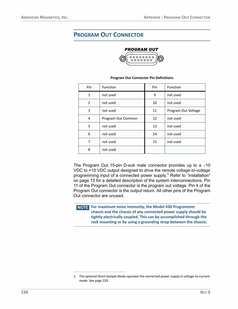
AMERICAN MAGNETICS, INC. APPENDIX : PROGRAM OUT CONNECTOR
PROGRAM OUT CONNECTOR
The Program Out 15-pin D-sub male connector provides up to a −10VDC to +10 VDC output designed to drive the remote voltage-to-voltageprogramming input of a connected power supply.1 Refer to “Installation”on page 13 for a detailed description of the system interconnections. Pin11 of the Program Out connector is the program out voltage. Pin 4 of theProgram Out connector is the output return. All other pins of the ProgramOut connector are unused.
NOTE For maximum noise immunity, the Model 430 Programmer chassis and the chassis of any connected power supply should be tightly electrically coupled. This can be accomplished through the rack mounting or by using a grounding strap between the chassis.
Program Out Connector Pin Definitions
Pin Function Pin Function
1 not used 9 not used
2 not used 10 not used
3 not used 11 Program Out Voltage
4 Program Out Common 12 not used
5 not used 13 not used
6 not used 14 not used
7 not used 15 not used
8 not used
1. The optional Short-Sample Mode operates the connected power supply in voltage-to-current mode. See page 229.
198 REV 9

AMERICAN MAGNETICS, INC. APPENDIX : QUENCH I/O CONNECTOR
QUENCH I/O CONNECTOR
The Quench I/O connector provides pins for external quench detectioninput, external rampdown input, quench detection output, and severalother Model 430 status output signals (refer to the table below). TheQuench I/O connector is a high density 15-pin D-sub male connector.The shell lugs of the connector are connected to the Model 430Programmer chassis ground.
Quench I/O Connector Pin Definitions
Pin Polarity Function
1n/a Quench Output
(Model 430 Programmer NO dry contacts)2
3 n/a Relay K3 Output (Model 430 Programmer NO dry con-tact - see Pin 8)
4 circuit common Quench Input(customer-suppled external NO dry contacts)NOTE: The Model 430 has a 1K Ohm pull-up resistor for this input.
5 +
6 circuit common External Rampdown Input(customer-supplied external NO dry contact)NOTE: The Model 430 has a 1K Ohm pull-up resistor for this input.
7 +
8 n/a Relay K3 Output (see Pin 3)
9n/a Magnet Energized Relay (K2) Output
(Model 430 Programmer NO dry contacts)10
11n/a At Target Relay (K4) Output
(Model 430 Programmer NO dry contacts)12
13n/a Leads Energized Relay (K5) Output
(Model 430 Programmer NO dry contacts)14
15 n/a Future input (not used)
REV 9 199

AMERICAN MAGNETICS, INC. APPENDIX : QUENCH I/O CONNECTOR
EXTERNAL QUENCH DETECTION INPUT
The external quench detection input allows the user to facilitate his ownquench detection circuitry, the output of which is wired to the Model 430Programmer. The external input overrides the internal quench detectionfunction of the Model 430 Programmer and cannot be disabled.
CAUTION The external quench detection input is a dry contact input, not galvanically isolated from the Model 430 Programmer internal circuitry. To avoid noise problems and potential damage to the Model 430 Programmer, it is very important that the dry contacts to which the input is connected be galvanically isolated from any external circuitry.
It is recommended that the external quench detection input be driven bythe contacts of a low level dry contact relay, which will galvanicallyisolate the input from all other circuitry.
When the external quench detection input pins (pins 4 and 5 of theQuench I/O connector) are shorted together, it is the same as if an Model430 Programmer internal quench detection occurred. Refer to page 123for details.
NOTE The Model 430 Programmer takes approximately 600 microseconds from the time it detects the external quench input to execute the quench condition process. Refer to page 124 for more information.
EXTERNAL RAMPDOWN INPUT
When enabled2, the external rampdown input initiates a rampdown ofthe magnetic field of the magnet when triggered.
CAUTION The external rampdown input is a dry contact input, not galvanically isolated from the Model 430 Programmer internal circuitry. To avoid noise problems and potential damage to the Model 430 Programmer, it is very important that the dry contacts to which the input is connected be galvanically isolated from any external circuitry.
It is recommended that the external rampdown input be driven by thecontacts of a low level dry contact relay, which will galvanically isolatethe input from all other circuitry.
When the external rampdown input pins (pins 6 and 7 of the Quench I/Oconnector) are shorted together for more than 10 milliseconds, theModel 430 Programmer enters external rampdown mode. If the magnet
2. Refer to “Enable External Rampdown” on page 94.
200 REV 9

AMERICAN MAGNETICS, INC. APPENDIX : QUENCH I/O CONNECTOR
is in driven mode, the Model 430 Programmer ramps the magnet field/current to zero. If the magnet is in persistent mode, the Model 430Programmer ramps the power supply to match the last known persistentmagnet current, turns on the persistent switch heater, waits the specifiedheated time (or detects the transition using the magnet voltage per thePSwitch Transition setting3) and then ramps the magnet field/current tozero.
This function may be used with the AMI Model 1700 Liquid LevelInstrument4. The level instrument has a NO relay associated with the lowlevel condition and this contact closure can be connected to the ExternalRampdown Input so that when a low helium level occurs in a system, themagnet is safely and automatically ramped down, preventing a magnetquench. AMI offers a cable for this purpose or the user can make asuitable cable to connect pins 5 and 6 of the Aux I/O connector of theModel 1700 instrument to pins 6 and 7 of the 430 Programmer, QuenchI/O connector.
CAUTION The separate external segmented-rampdown option described below ignores the Voltage Limit during the rampdown process.
NOTE If the number of external-rampdown ramp segments is set to zero, the modified rampdown is not used and the standard ramp rate table will be effective during external rampdown. The Model 430 Programmer defaults to an empty rampdown table (number of segments equal zero).
A separate, optional segmented-ramp-rate table is available for externalrampdown. This option is accessible only via the external interfacecommands (see page 167).
EXTERNAL QUENCH DETECTION OUTPUT
The external quench detection output is a set of dry contacts (pins 1 and2 of the Quench I/O connector) which close when the Model 430Programmer internal circuitry detects a quench condition. Note that theModel 430 Programmer internal quench detection must be enabled toassure that the Model 430 Programmer will indicate a detected quench(see page 89).
The contacts remain shorted (when a quench has been detected) untilthe RESET QUENCH SHIFT-key is used to clear the quench condition.
3. See page 85.4. Or the Model 13x series of Liquid Helium Level Instruments for legacy systems.
REV 9 201

AMERICAN MAGNETICS, INC. APPENDIX : AUXILIARY INPUTS CONNECTOR
AUXILIARY INPUTS CONNECTOR
The Aux Inputs connector provides pins for external voltage inputs,reserved for future use. The shell lugs of the connector are connected tothe Model 430 Programmer chassis ground. The Aux Inputs connector isa high density 15-pin D-sub female connector.
Each input pin has a 1 megohm resistor to analog circuit common. Theinputs are differential inputs. Aux Input 1 and Aux Input 2 have a ± 1 Vnominal input voltage range. Aux Input 3, Aux Input 4, Aux Input 5 andAux Input 6 have a ±10 V nominal input voltage range.
Aux Inputs Connector Pin Definitions
Pin Function Pin Function
1 Aux Input 1 + (Vm +)a
a. Auxiliary Input 1 is consumed by the magnet voltage input internally connected to the Magnet Station connector (pins 11+ and 12–) for Model 430 units that ship with version 3.00 firmware or later. It is used for the magnet voltage-based switch transition detection logic and is not available for general use. See page 85 for more information.
9 Aux Input 4 –
2 Aux Input 1 – (Vm –) 10 not used
3 Aux Input 2 + (Vss +)b
b. Auxiliary Input 2 is used for the sample voltage taps (Vss) for the optional Short-Sample operational mode. See page 229 for more information.
11 Aux Input 5 +
4 Aux Input 2 – (Vss –) 12 Aux Input 5 –
5 not used 13 Aux Input 6 +
6 Aux Input 3 + (Tmax +)c
c. Auxiliary Input 3 is optionally used for the Tmax 0 to 10VDC signal from an external tem-perature monitor. See page 93 for more information.
14 Aux Input 6 –
7 Aux Input 3 – (Tmax –) 15 not used
8 Aux Input 4 +
202 REV 9

AMERICAN MAGNETICS, INC. APPENDIX : ETHERNET CONNECTOR
ETHERNET CONNECTOR
The Ethernet connector provides visual (LED) indications of the status:1. Steady green when a link is established.
2. Blinking amber for network activity as network packets are received or trans-mitted.
Ethernet RJ-45 Connector Pin Definitions
Pin Mnemonic Function
1 TXD+ Transmit differential output +
2 TXD– Transmit differential output –
3 RXD+ Transmit differential input +
4not used
5
6 RXD– Transmit differential input –
7not used
8
REV 9 203

AMERICAN MAGNETICS, INC. APPENDIX : RS-232 CONNECTOR
RS-232 CONNECTOR
The RS-232 connector is a standard DTE 9-pin D-sub male connector
RS-232 Connector Pin Definitions
Pin Mnemonic Function
1 DCD Data Carrier Detect
2 RXD Receive Data
3 TXD Transmit Data
4 DTR Data Terminal Ready
5 GND Signal Ground
6 DSR Data Set Ready
7 RTS Request To Send
8 CTS Clear to Send
9 RI Ring Indicator
PC (DB9)-to-Model 430 RS-232 Cable Connections
PC (DTE)DB9 Pin
Model 430 (DTE) DB9 Pin
1, 6 4
2 3
3 2
4 6, 1
5 5
7 8
8 7
204 REV 9

AMERICAN MAGNETICS, INC. APPENDIX : ABBREVIATIONS AND ACRONYMS USED IN THIS MANUAL
ABBREVIATIONS AND ACRONYMS USED IN THIS MANUAL
Abbreviations and Acronyms
Term Meaning
AC; ac Alternating Current; strictly, electrical current that periodically reverses direc-tion. Typically used also to describe an electrical power source in terms of the voltage. For example, 240 VAC.
ASCII American Standard Code for Information Interchange; numerical representa-tion of characters such as 'a' or '@' or an action (such as line-feed); 'plain' raw text with no formatting such as tabs, bold or underscoring
<CR> Text carriage-return (\r) character
CT Current Transducer
CTS DTE clear-to-send signal
DB9 Type of electrical connector containing 9 pins arranged in two parallel rows of 4 pins and 5 pins each)
DB15 Type of electrical connector containing 15 pins arranged in two parallel rows of 7 pins and 8 pins each
D-Sub Term referring to the family of connectors containing an odd number of pins in two parallel rows with a 1-pin difference in pins-per-row (DB9, DB15, and DB25 are most common)
DC; dc Direct Current; strictly, electrical current that flows in only one direction. Typ-ically used also to describe an electrical power source in terms of the voltage. For example, 12 VDC.
DCE Data Communication Equipment: The devices of a communications network, such as modems, that connect the communication circuit between the data source and destination (DTE’s).
DHCP Dynamic Host Configuration Protocol; a computer networking protocol which dynamically distributes the IP address to networked devices
di/dt Current flow rate of change
DSP Digital Signal Processing; digital representation and processing of signals typi-cally converted to/from analog signals external to the processor.
DTE Data Terminal Equipment: the source or destination of data in a communica-tion connection. DTE’s are connected to DCE which in turn is connected to the communication channel.
EFT Electrical Fast Transient
EMC Electromagnetic Compatibility
Eo Power supply output voltage
REV 9 205

AMERICAN MAGNETICS, INC. APPENDIX : ABBREVIATIONS AND ACRONYMS USED IN THIS MANUAL
ESD Electrostatic Discharge
FIFO First-in / First-out
FTP File Transfer Protocol
i, I Electrical current flow
Ic, Ic Critical current, the maximum recommended current for at a given supercon-ductor temperature
Io Power supply output current
IEC International Electrotechnical Commission
IEEE Institute of Electrical and Electronics Engineers
I/O Input/Output; The hardware and associated protocol that implement com-munication between information processing systems and/or devices. Inputs are the signals or data received by the system or device, and outputs are the signals or data sent from it.
IP Internet Protocol; when used with “address”, refers to a numerical internet address
IR The product I x R: the voltage developed by electrical current flow (I) through a resistance (R)
kG kilogauss: a magnetic field unit of measurement
L Electrical circuit inductance measured in henries; superconducting magnets act as nearly perfect inductors when at superconducting temperatures.
LED Light-Emitting Diode; a semiconductor device that emits light when energized - used for visual status indication
<LF> Text line-feed (\n) character
LHe Liquid helium
LN2 Liquid nitrogen
Max Maximum
Min Minimum
ms, msec Milli-seconds
nom Nominal
P/S Persistent switch; a switch which, if perfectly realized, has zero resistance when at superconducting temperatures. An integrated heater element allows the switch to be heated for purposes of charging or discharging a supercon-ducting magnet.
pk Peak
PSw Persistent switch
Abbreviations and Acronyms (Continued)
Term Meaning
206 REV 9

AMERICAN MAGNETICS, INC. APPENDIX : ABBREVIATIONS AND ACRONYMS USED IN THIS MANUAL
PSwitch Persistent switch
RF Electromagnetic radiation in the radio frequency spectrum
Rlead Electrical circuit lead or wiring resistance
RTS DTE ready-to-send signal
RS-232 RS-232 is a long-established standard and protocol for relatively low speed serial data communication between computers and related devices; origi-nally established for teletypewriter communication.
SCPI Standard Commands for Programmable Instruments
STP Standard Temperature and Pressure
T Tesla: a magnetic field unit of measurement = 10 kilogauss
Temp Temperature
V Volts
V-I Voltage-controls-Current; the power supply mode in which the Program Out voltage is in direct ratio to the output current of a connected power supply; used for Short-Sample mode by the Model 430 Programmer.
V-V Voltage-controls-Voltage; the power supply mode in which the Program Out voltage is in direct ratio to the output voltage of a connected power supply; used by the Model 430 Programmer for superconducting magnet operation.
VA Volt-amperes (V x I); a unit of electrical reactive power
VFD Vacuum Fluorescent Display; an electronic display device which, unlike liquid crystal displays, can emit very bright, high contrast light in various colors.
Vlead Voltage (i x R) developed across circuit lead or wiring resistance due to high current flow
Vm Magnet voltage
Vs Power supply voltage
Vss Short-sample voltage
Abbreviations and Acronyms (Continued)
Term Meaning
REV 9 207

AMERICAN MAGNETICS, INC. APPENDIX : REMOTE COMPUTER COMMUNICATION WITH THE MODEL 430
REMOTE COMPUTER COMMUNICATION WITH THE MODEL 430
COMMUNICATION VIA RS-232
1. Using serial null modem adapter (and possibly a gender changer)5, connect the DB9 RS-232 connector on the rear of the Model 430 Programmer to a standard USB-to-serial cable6 connected to a computer.
2. Start a terminal emu-lator program on the remote computer. As an example, this pro-cedure will use the open-sourced Tera Term program7 run-ning on a Windows machine. You are greeted immediately with the Tera Term New Connection dia-log.
3. Choose the Serial option and then the Port to which the Model 430 is con-nected. This example illustrates COM20: USB Serial Port (COM20), which in this example is the port assigned by Windows to a USB-to-serial adapter cable. Press OK.
4. Use the Setup | Serial Port... menu com-mand in Tera Term to show the serial parameters dialog. Set the parameters as shown at right per page 143 (Port selec-tion is specific to your setup).
5. Mouser Electronics offers a compact null-model/gender changer: see part # 515-140-448-R.6. AMI recommends FTDI USB-to-serial cables. See DigiKey part # 768-1084-ND.7. The Tera Term application is open-sourced and is available at https://ttssh2.osdn.jp/
index.html.en. A Windows installer for a recent version (not guaranteed to be the latest) is also included on the internal Model 430 web page, see page 226.
208 REV 9
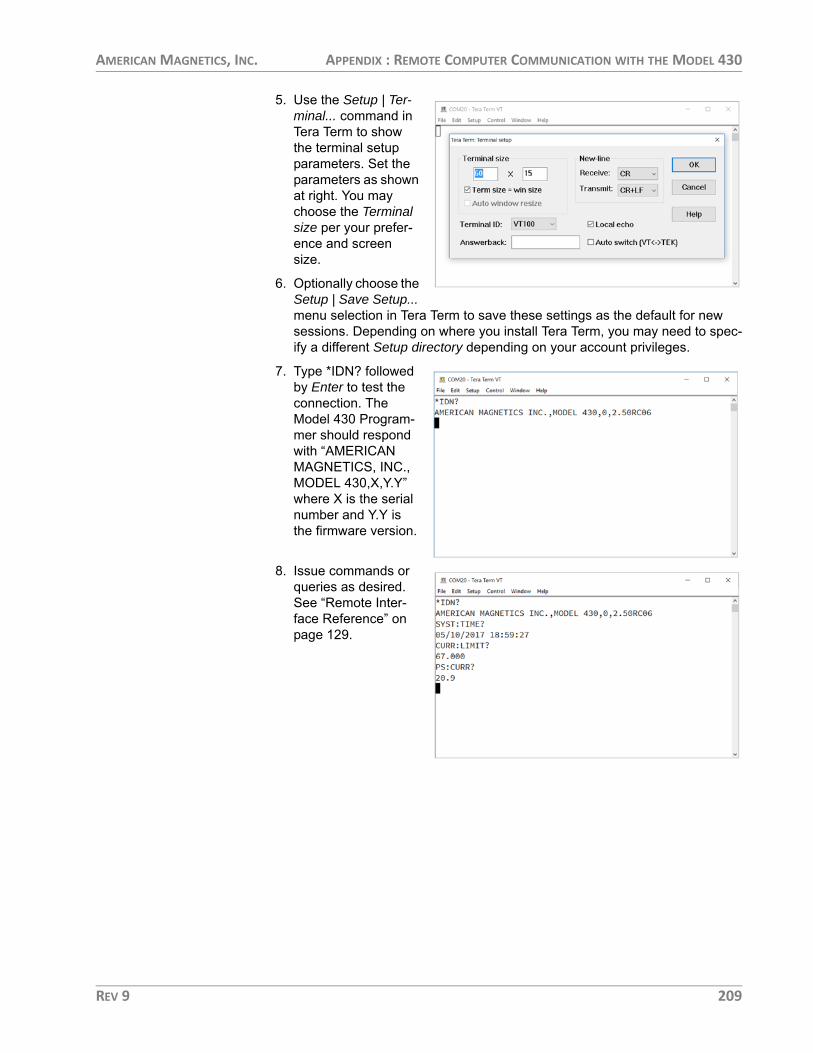
AMERICAN MAGNETICS, INC. APPENDIX : REMOTE COMPUTER COMMUNICATION WITH THE MODEL 430
5. Use the Setup | Ter-minal... command in Tera Term to show the terminal setup parameters. Set the parameters as shown at right. You may choose the Terminal size per your prefer-ence and screen size.
6. Optionally choose the Setup | Save Setup... menu selection in Tera Term to save these settings as the default for new sessions. Depending on where you install Tera Term, you may need to spec-ify a different Setup directory depending on your account privileges.
7. Type *IDN? followed by Enter to test the connection. The Model 430 Program-mer should respond with “AMERICAN MAGNETICS, INC., MODEL 430,X,Y.Y” where X is the serial number and Y.Y is the firmware version.
8. Issue commands or queries as desired. See “Remote Inter-face Reference” on page 129.
REV 9 209

AMERICAN MAGNETICS, INC. APPENDIX : REMOTE COMPUTER COMMUNICATION WITH THE MODEL 430
COMMUNICATION VIAETHERNET
1. Connect the Model 430 Programmer RJ-45 Ethernet port either directly to a host computer or through a computer network on which the host computer resides:
a. For a host computer on a network, connect a standard Ethernet cable between the Model 430 and the network.
b. For a direct hardwired connection between the Model 430 and a host computer, use a “null-modem” or “crossover” Ethernet cable connected from the Model 430 directly to the host computer.
NOTE Most modern computers will negotiate the direct connection cross-over automatically with a standard Ethernet cable.
2. Turn on the Model 430 and press ENTER at the “Turn on power supply . . .” prompt.
3. Press MENU to enter the menu system.
4. Use < >/< > to navigate to the Net Settings submenu and press ENTER.
5. Use < >/< > as necessary to navigate to Addr Assignment (Present).
NOTE The Addr Assignment (Present) must show “DHCP” as originally set by AMI.
NOTE In the following step, the IP Address is the four part number separated by periods (.), and will change with each Ethernet connection.
6. Use < >/< > to locate IP Address (Present), similar to that shown below:
7. Make note of the IP Address (Present).
8. Start a terminal emu-lator program on the remote computer. As an example, this pro-cedure will use the open-sourced Tera Term program8 run-ning on a Windows machine. You are greeted immediately with the Tera Term New Connection dia-log.
0.00 A — IP Address (Present) 0.00 Vs 192.168.1.12 (DHCP)
210 REV 9

AMERICAN MAGNETICS, INC. APPENDIX : REMOTE COMPUTER COMMUNICATION WITH THE MODEL 430
9. Choose the TCP/IP option and then the Host address for the Model 430 that was determined from the previous Step 7. This example illustrates 192.168.1.12. Choose the Service | Other and enter TCP port # 7180. Press OK.
10.The computer will connect with the Model 430 Program-mer and display the welcome message.
11.Use the Setup | Ter-minal... command in Tera Term to show the terminal setup parameters. Set the parameters as shown at right. You may choose the Terminal size per your prefer-ence and screen size.
12.Optionally choose the Setup | Save Setup... menu selection in Tera Term to save these settings as the default for new sessions. Depending on where you install Tera Term, you may need to spec-ify a different Setup directory depending on your account privileges.
13.Type *IDN? followed by Enter to test the connection. The Model 430 Program-mer should respond with “AMERICAN MAGNETICS, INC., MODEL 430,X,Y.Y” where X is the serial number and Y.Y is the firmware version.
8. The Tera Term application is open-sourced and is available at https://ttssh2.osdn.jp/index.html.en. A Windows installer for a recent version (not guaranteed to be the latest) is also included on the internal Model 430 web page, see page 226.
REV 9 211

AMERICAN MAGNETICS, INC. APPENDIX : REMOTE COMPUTER COMMUNICATION WITH THE MODEL 430
14.Issue commands or queries as desired. See “Remote Inter-face Reference” on page 129.
212 REV 9

AMERICAN MAGNETICS, INC. APPENDIX : UPGRADING THE MODEL 430 FIRMWARE VIA FTP
UPGRADING THE MODEL 430 FIRMWARE VIA FTP
NOTE IMPORTANT If the Model 430 is being upgraded from Version 1.59 or earlier, proceed to the upgrade procedure in section on page 221.
NOTE These instructions apply specifically to the Microsoft Windows operating system. For other operating systems, please make adjustments as appropriate.
HARDWARE AND SOFTWARE REQUIREMENTS1. Personal Computer (PC) networked by Ethernet to the system on which the
target Model 430 resides,or
PC connected directly to the target Model 430 via a “null-modem” or “cross-over” Ethernet cable.
NOTE Most modern computers will negotiate the direct connection cross-over automatically with a standard Ethernet cable.
2. The Model430.exe upgrade file extracted from the zip file (typically of the same name) provided by AMI.
3. FileZilla9 or other appropriate FTP Client installed on the PC. For this proce-dure an open-source FTP client called FileZilla is illustrated.
Also included is an alternative upload procedure using the command-line interface of the built-in Windows FTP client that requires no software installa-tion (see page 220).
PREPARATION 1. Install FileZilla or another appropriate FTP Client on the PC that will used for the upgrade.
2. The AMI Model 430 can be upgraded through a file server, or similar net-work, or via direct Ethernet connection to the PC:
a. Via Network:
(1.) Make a new “Upgrade” folder located in an appropriate location on the file server.
(2.) Extract and save the AMI-supplied upgrade-file, Mod-el430.exe, to the new folder.
(3.) Ensure that the PC is connected to the network.
9. Available free at http://filezilla-project.org/
REV 9 213

AMERICAN MAGNETICS, INC. APPENDIX : UPGRADING THE MODEL 430 FIRMWARE VIA FTP
(4.) Ensure the Model 430 is connected to the network via standard Ethernet cable.
b. Direct PC-to-Model 430: (1.) Make a new “Upgrade” folder located in an appropriate
location on the PC. (2.) Extract and save the AMI-supplied upgrade-file, Mod-
el430.exe, to the new folder. Additional files such as an updated manual PDF (Model430Manual.pdf) and updat-ed Magnet-DAQ app (MagnetDAQ-setup.msi) may also be included in the update.
(3.) Connect the PC to the Model 430 using a “null-modem” Ethernet cable (also referred to as an Ethernet “cross-over” cable). Modern computer equipment may not re-quire a crossover cable as the Ethernet ports can automatically sense the necessary configuration.
3. Turn on the Model 430 and press ENTER at the “Turn on power supply . . .” prompt.
4. Press MENU to enter the menu system.
5. Use < >/< > to navigate to Net Settings submenu and press ENTER.
6. Use < >/< > as necessary to navigate to Addr Assignment (Present).
NOTE The Addr Assignment (Present) must show “DHCP” as originally set by AMI.
NOTE In the following step, the IP Address is the four part number separated by periods (.), and will change with each Ethernet connection.
7. Use < >/< > to locate IP Address (Present), similar to that shown in Fig-ure 1.
8. Make note of the IP Address (Present).
UPLOAD PROCEDURE USING FILEZILLA
An alternative upload procedure is provided on page 220 that uses thebuilt-in command line interface for Windows FTP. It requires no softwareinstallation. If you are averse to command lines, then proceed with thefollowing steps to use FileZilla or your other favorite FTP Client.
0.00 A — IP Address (Present) 0.00 Vs 169.254.243.199 (DHCP)
214 REV 9

AMERICAN MAGNETICS, INC. APPENDIX : UPGRADING THE MODEL 430 FIRMWARE VIA FTP
NOTE The result of each of the following steps is depicted in the figure appearing above or below the action described. The actual screens will vary depending on the files and file structure on the users PC or file server, and whether FileZilla is used as the FTP Client.
1. Open the FileZilla client application—a screen similar to the following will appear:
2. Enter the following information in the applicable fields:
a. Host: the IP Address (Present) as noted previously
b. User Name: model430admin
c. Password: supermagnets
REV 9 215

AMERICAN MAGNETICS, INC. APPENDIX : UPGRADING THE MODEL 430 FIRMWARE VIA FTP
d. Port: 21
3. Click the Quickconnect button to connect to the Model 430 – the Remote Site section of the screen will populate.
216 REV 9

AMERICAN MAGNETICS, INC. APPENDIX : UPGRADING THE MODEL 430 FIRMWARE VIA FTP
4. On the Local Site (left side representing your PC or server file system), navi-gate to the folder containing the Model430.exe upgrade file (the folder name will be that which was previously given the new “upgrade” folder.).
5. Double-click to open the “upgrade” folder on the Local Site (left side) of the screen – the Model430.exe file will appear.
REV 9 217

AMERICAN MAGNETICS, INC. APPENDIX : UPGRADING THE MODEL 430 FIRMWARE VIA FTP
6. On the Remote Site (right side representing the Model 430 files), select the Upgrade folder.
7. Double-click the Upgrade folder to open it (the folder will be empty).
218 REV 9

AMERICAN MAGNETICS, INC. APPENDIX : UPGRADING THE MODEL 430 FIRMWARE VIA FTP
8. Select the Model430.exe file from the Local Site (left side) and drag it to the open Upgrade folder on the Remote Site (right side)10.
9. If an updated manual PDF, Model430Manual.pdf, and updated remote con-trol interface app, MagnetDAQ-setup.msi, are provided with the firmware update, then navigate to the WebServer folder on the Model 430 and replace those files with the new versions. If the WebServer folder does exist on the Model 430, please contact an AMI Technical Support Representative for fur-ther instructions.
10.Turn off the Model 430.
11.Close the FTP program.
NOTE This completes the firmware upgrade. When the Model 430 power is turned on again after powering down, the firmware will automatically upgrade based on the Model430.exe file just placed in its Upgrade folder. View the “Loading. . . . .” screen as the Model 430 is “booting” up: the new Firmware Version will momentarily be displayed.
12.Reboot the Model 430 Programmer by switching the power switch on the front panel off for 10 seconds and then turning the switch back on.
13.Verify that after approximately 20 seconds, the Model 430 display briefly shows the new (upgraded) firmware version11:
10. Alternatively, copy Model430.exe from the Local Site and paste it to the open folder on the Remote Site.
AMI Model 430 ProgrammerFirmware Version: 2.50
REV 9 219

AMERICAN MAGNETICS, INC. APPENDIX : UPGRADING THE MODEL 430 FIRMWARE VIA FTP
ALTERNATIVE UPLOAD PROCEDURE USING WINDOWS FTP
Modern versions of Microsoft Windows (and other operating systemssuch as Linux) include a command line-based client version of FTP as astandard feature. There is no requirement to install a GUI FTP Client toperform the Model 430 firmware upgrade.
First, perform steps 2 through 8 as described in the Preparation sectionon page 213 (omit the FileZilla installation of step 1).
To actually perform the FTP upload to the Model 430, do the followingsteps:1. Open a Windows Command Line instance and navigate to the folder where
you stored the firmware upgrade during the preparation steps.
2. FTP to the instrument address on the network as identified during the prepa-ration. The entire command line process is illustrated below:
3. Login with user name “model430admin” and password “supermagnets” (do not include the quotes).
4. Type “bin” and press Enter to ensure a binary mode transfer.
5. Type “cd Upgrade” and Enter to change to the target folder for the firmware upload.
6. Type “put Model430.exe” and Enter.
7. Type “quit” and Enter to exit.
8. Cycle power on the Model 430 and observe the firmware version banner during boot.
11. Version 2.50 is used only for purposes of this example.
220 REV 9

AMERICAN MAGNETICS, INC. APPENDIX : UPGRADING THE MODEL 430 FIRMWARE VIA FLASH CARD READER
UPGRADING THE MODEL 430 FIRMWARE VIA FLASH CARD READER
NOTE These instructions are intended primarily for a Model 430 being upgraded from Version 1.59 or earlier. If the current version is v1.60 or later, upgrade should be performed via FTP according to page 213.
NOTE These instructions apply specifically to the Microsoft Windows operating system. For other operating systems, please make adjustments as appropriate.
This is a one-time only procedure as future upgrades will be handled viathe Ethernet communications connection on the rear panel of theinstrument. An operating system file on the Compact Flash (CF) cardmounted inside the Model 430 must be updated to enable the new webserver functionality. The file is not accessible via FTP which means theModel 430 cover must be removed, the CF card removed, and the filesupdated using a CF card reader. Once this upgrade is completed, the CFcard should not have to be removed in order to perform future upgrades.
HARDWARE AND SOFTWARE REQUIREMENTS1. The zip file, Model 430 flash card update.zip, is required for this upgrade; the
zipped files are to be extracted and copied to the CF card.
2. Host computer on a network to which the Model 430 can be connected by standard Ethernet cable
or Host computer that can be connected directly to the target Model 430 via an Ethernet “null-modem” or “crossover” cable.
NOTE Most modern computers will negotiate the direct connection cross-over automatically with a standard Ethernet cable.
3. Standard Ethernet cable or Ethernet “null-modem” cable, as appropriate.
PREPARATION Complete the following in preparation for the upgrade.1. Power down and unplug the Model 430.
2. Remove the cover from the Model 430 as follows:
a. Remove the screws securing the cover on the back edges of the instrument (two near each side of the instrument).
REV 9 221
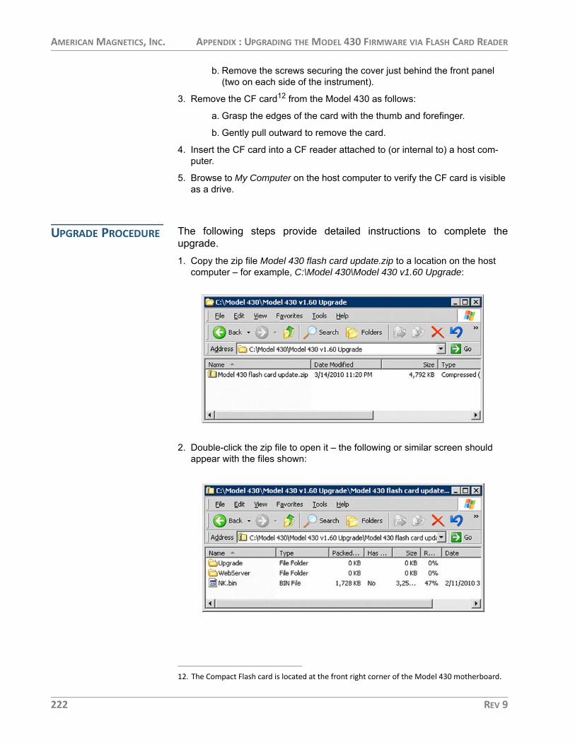
AMERICAN MAGNETICS, INC. APPENDIX : UPGRADING THE MODEL 430 FIRMWARE VIA FLASH CARD READER
b. Remove the screws securing the cover just behind the front panel (two on each side of the instrument).
3. Remove the CF card12 from the Model 430 as follows:
a. Grasp the edges of the card with the thumb and forefinger.
b. Gently pull outward to remove the card.
4. Insert the CF card into a CF reader attached to (or internal to) a host com-puter.
5. Browse to My Computer on the host computer to verify the CF card is visible as a drive.
UPGRADE PROCEDURE The following steps provide detailed instructions to complete theupgrade.1. Copy the zip file Model 430 flash card update.zip to a location on the host
computer – for example, C:\Model 430\Model 430 v1.60 Upgrade:
2. Double-click the zip file to open it – the following or similar screen should appear with the files shown:
12. The Compact Flash card is located at the front right corner of the Model 430 motherboard.
222 REV 9

AMERICAN MAGNETICS, INC. APPENDIX : UPGRADING THE MODEL 430 FIRMWARE VIA FLASH CARD READER
3. Choose File > Extract All… to start the extraction wizard:
4. Click Next until prompted with Select a Destination:
5. Browse to My Computer and choose the top level (root) of the drive associ-ated with the CF card (for example E:\ or G:\) and select Next.
REV 9 223

AMERICAN MAGNETICS, INC. APPENDIX : UPGRADING THE MODEL 430 FIRMWARE VIA FLASH CARD READER
6. When prompted with the Confirm File Replace dialog, select Yes To All.
7. When the extraction process concludes, select Finish.
8. Close all open windows for the CF drive.
9. Use the Safely Remove Hardware icon in the tool tray to eject (unmount) the CF card from the host computer.
10.Remove the CF card from the card reader.
11.Re-install the CF card in the Model 430 - ensure the card is seated properly.
12.Re-install the cover on the Model 430 using the previously removed screws.
NOTE The Model 430 and the host computer must share the same network address scheme and be attached to the same physical network in the following process.
13.Verify that the web interface is functioning correctly as follows:
a. Connect the Model 430 to the host computer using one of the following two methods:
(1.) Via Ethernet cable to the same physical network as the host computer.
(2.) Via “crossover” or “null modem” Ethernet cable directly to the host computer’s Ethernet port.
b. Plug in and power up the Model 430.
c. As the Model 430 boots up, watch the front display and verify that it shows Firmware Version: 1.6213 (or other version being upgraded to).
d. Press <ENTER> at the Turn on power supply prompt.
e. Using the Model 430 menu system, Menu > Net Settings > IP Address (Present), determine the IP Address of the Model 430.
13. Display time may vary depending on network speed - refer to section on page 191.
224 REV 9
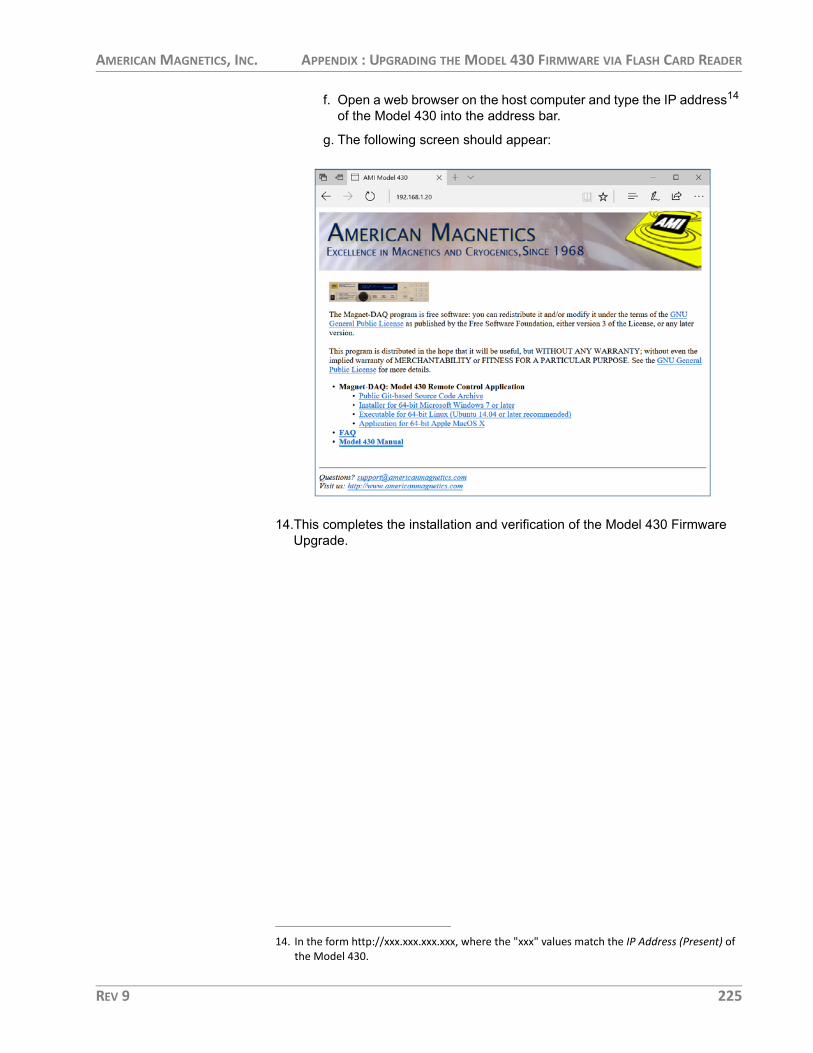
AMERICAN MAGNETICS, INC. APPENDIX : UPGRADING THE MODEL 430 FIRMWARE VIA FLASH CARD READER
f. Open a web browser on the host computer and type the IP address14 of the Model 430 into the address bar.
g. The following screen should appear:
14.This completes the installation and verification of the Model 430 Firmware Upgrade.
14. In the form http://xxx.xxx.xxx.xxx, where the "xxx" values match the IP Address (Present) of the Model 430.
REV 9 225

AMERICAN MAGNETICS, INC. APPENDIX : MAGNET-DAQ: MODEL 430 REMOTE CONTROL
MAGNET-DAQ: MODEL 430 REMOTE CONTROL15
The Model 430 can be accessed via a network connection16 with fullyfunctional control.17 This is accomplished through the Ethernetconnection on the rear panel using TCP/IP protocol via a host computer.The connection and control can be established through a locallyconnected computer or remotely through a network or even the Internet;the actual control is accomplished through the SCPI remote commandsas documented in the “Remote Interface Reference” section beginningon page 129.
The open-sourced18 Magnet-DAQ application is provided to manage theremote control with a familiar graphical interface. The source code andlatest binary (i.e. pre-compiled) downloads for the application areavailable at:
https://bitbucket.org/americanmagneticsinc/magnet-daq
To utilize the Magnet-DAQ application, the Model 430 Programmer RJ-45 Ethernet port must be connected either directly to a host computer orthrough a computer network on which the host computer resides or candirectly access: 1. For a host computer on a network, connect a standard Ethernet cable
between the Model 430 and the network.
2. For a direct hardwired connection between the Model 430 and a host com-puter, use a “null-modem” or “crossover” Ethernet cable connected from the Model 430 to the host computer.
NOTE Most modern computers will negotiate the direct connection cross-over automatically with a standard Ethernet cable.
3. Once connected, plug in and power up the Model 430.
4. Press <ENTER> after responding to the “Turn on power supply . . .” prompt.
NOTE Allow up to 90-seconds (from power-up) for the TCP/IP link between the Model 430 and host computer to be established.
In order to access the Model 430 using the Magnet-DAQ application, the Model 430 IP Address must be known. The IP Address can be determined after Model 430 power-up. The following example illustrates how the IP Address may be determined using the Model 430 menu system:
15. Requires Model 430 version 2.50 or later firmware.16. Third-party remote software, such as National Instruments LabVIEW, can also be used.17. With the exception of the Power ON/OFF switch.18. Subject to the GPL version 3.0 license.
226 REV 9

AMERICAN MAGNETICS, INC. APPENDIX : MAGNET-DAQ: MODEL 430 REMOTE CONTROL
5. IP Address: Menu > Net Settings > IP Address (Present).
Open a web browser on the host computer. In the address field, type the IP Address, and press <ENTER>. For example:
The following initial (home) screen should appear:
The Magnet-DAQ: Model 430 Remote Control Application section is the pri-mary feature of this HTML page. Download links for the pre-compiled install-ers or executables are provided for various computer platforms.
NOTE Please note that the version provided was current at the time the Model 430 was shipped. Check the AMI website, or the on-line Git-based Source Code Archive, for updated versions of the Magnet-DAQ application. Updated versions of the Magnet-DAQ may also require updating the Model 430 firmware.
The initial screen also includes links to the Model 430 Manual in Adobe PDF form along with the FAQ (Frequently Asked Questions) related to the Mag-
0.00 A — IP Address (Present) 0.00 Vs 192.168.1.20 (DHCP)
IP Address Entry in Browser Address Field
Initial Screen for Browser Access of the Model 430
REV 9 227

AMERICAN MAGNETICS, INC. APPENDIX : MAGNET-DAQ: MODEL 430 REMOTE CONTROL
net-DAQ application (all stored in the Model 430 firmware). There are also links to the AMI website and an e-mail form for contacting AMI Customer Support.
6. Choose the desired Magnet-DAQ version for the appropriate operating sys-tem and follow the installation instructions for each.
The Windows version installation will be illustrated herein which is provided in the form of an installer. After the installer download is complete, simply launch the installer and follow the familiar installation wizard (using the Next button) to complete the process:
7. Launch the Magnet-DAQ application, choose the Setup panel, and enter the IP address discovered in Step 5 above:
8. Press the Connect toolbar button to start communication.
9. Use the provided Magnet-DAQ interface to remotely control the Model 430. The Keypad panel provides a remote keypad function. For more details, refer to the integrated Help provided in the Magnet-DAQ application.
...
Windows-version Installation Wizard for the Magnet-DAQ Application
228 REV 9

AMERICAN MAGNETICS, INC. APPENDIX : SHORT-SAMPLE MODE
SHORT-SAMPLE MODE19
The Model 430 also features the ability to operate as a short-samplecontroller. Short-sample refers to samples of superconducting wires ofrelatively short length as compared to lengths required for a woundmagnet, typically tested in the presence of various background magneticfield levels. The short-sample test is designed to determine criticalcurrent density limits for various field levels for the wire sample.
In the Short-Sample Mode, the Model 430 commands a connectedpower supply in voltage-controls-current mode, i.e. the Program Outconnector (see page 198) outputs a voltage that corresponds to thecurrent output limit of a connected power supply. The connected powersupply must support remote current limit programming by externalanalog voltage.
CAUTION The Short-Sample Mode includes a sample quench detection feature. It is recommended that the sample quench detection always be ON and that voltage taps across the sample be connected to Auxiliary Input 2. It is possible to destroy a sample (via overheating) if the Model 430 is allowed to continue ramping or hold a current for a sample that has quenched. Samples should not be left unattended when actively ramping the sample current.
If the sample has quenched, the Model 430 will indicate the sample current at which the quench was detected and immediately command and hold the supply output current at 0 A until the sample quench detection state is cleared.
The typical system setup for short-sample testing will require a dataacquisition computer to query and record the sample voltage vs. samplecurrent and an application to plot the real-time result.
In Short-Sample Mode several features of the Model 430 applicable onlyto operation with a magnet are disabled. The changes include:• All menu items associated with the Persistent Switch operation are removed.• The Voltage Limit function is removed.• The units display for current is always amperes since there is no magnet
connected to the 430 with an associated coil constant (only the short-sam-ple).
• The sample voltage is measured via Auxiliary Input 2 (see page 202) and is reported in the default display as Vss in microvolts. An external gain factor of
19. Contact an AMI Technical Support Representative for details on how the Short-Sample Mode can be enabled and the latest data acquisition options for microvolt sampling.
REV 9 229

AMERICAN MAGNETICS, INC. APPENDIX : SHORT-SAMPLE MODE
10,000 is required for the sample voltage signal connected to Auxiliary Input 2 in Short-Sample Mode.20
NOTE The sample voltage must be connected to the Auxiliary Input 2 for the sample quench detection feature to function. Sample quench detection is defined as a sample current magnitude greater than 90 microvolts. The quench threshold of 90 microvolts is a fixed internal parameter.
• The custom Supply parameter “V-V Mode Input Range” is changed to “V-I Mode Input Range” to reflect voltage-commands-current operation of a con-nected power supply.
• The Load submenu of the Setup menu is limited to four parameters: Stability Setting, Current Limit, Sample Voltage Null, and Sample Quench Detect.
A Stability Setting of 0% is recommended for Short-Sample Mode unless otherwise directed by an AMI Technical Support Representative.
The Current Limit in this context refers to the maximum allowable current through the short-sample under test.
The Sample Voltage Null feature when exercised will quickly average several sample voltage (Vss) measurements and determine an offset to apply to the sample voltage to report 0 Volts for the Vss display and remote query. This offset is not saved between power cycles of the Model 430 and may be exer-cised as many times as desired to null out sample voltage offsets.
• The following remote commands and queries generate the error:
-109,”N/A in present mode”
when the Model 430 is operating in Short-Sample Mode:
CONFigure:VOLTage:LIMitCONFigure:COILconstCONFigure:RAMPDown (all subcommands)CONFigure:RAMP:RATE:FIELDCONFigure:FIELD:UNITSCONFigure:PSwitch (all subcommands)
20. AMI offers an external low-noise amplifier to scale microvolt sample voltages to a range that can be read by AUX Input 2.
+50.00 A — Status: Holding+24.53 Vss Short-Sample Mode
+50.00 A — Sample Voltage (Vss) Null+24.53 Vss Press ENTER to Zero Vss
230 REV 9

AMERICAN MAGNETICS, INC. APPENDIX : SHORT-SAMPLE MODE
CONFigure:LOCK:PSwitch:CONTRolCONFigure:LOCK:PSwitch:SETtingsCONFigure:LOCK:VOLTage:LIMitCONFigure:LOCK:VOLTage:VS-VMCONFigure:LOCK:QUench:RATECONFigure:LOCK:FIELD-CURRentCONFigure:LOCK:FIELD:UNITSCONFigure:LOCK:COILconstCONFigure:LOCK:ABsorberCONFigure:LOCK:RAMPDownCONFigure:QUench:RATECONFigure:ABsorberINDuctance?VOLTage:SUPPly?VOLTage:LIMit?VOLTage:MAGnet?CURRent:MAGnet?COILconst?PSwitch? (all subcommands)PERSistent?LOCK:PSwitch:CONTRol?LOCK:PSwitch:SETtings?LOCK:CURRent:RATING?LOCK:VOLTage:LIMit?LOCK:VOLTage:VS-VM?LOCK:QUench:RATE?LOCK:FIELD-CURRent?LOCK:FIELD:UNITS?LOCK:COILconst?LOCK:ABsorber?LOCK:RAMPDown?QUench:RATE?ABsorber?RAMP:RATE:FIELD?FIELD:MAGnet?FIELD:TARGet?FIELD:UNITS?FIELD:PRESent?
• The following remote queries are available only in Short-Sample Mode:
CURRent:SAMple?Returns the sample current in amperes.
VOLTage:SAMple?Returns the sample voltage in microvolts.
REV 9 231

AMERICAN MAGNETICS, INC. APPENDIX : SHORT-SAMPLE MODE
232 REV 9

AMERICAN MAGNETICS, INC. INDEXIndex
Aabbreviations and acronyms 205
absolute limits 128
AMI internet e-mail address 191
AMI web address 191
applicable hardware x
Bbeep
editing PSw P/S ramp rate 64editing ramp rate 64error messages 178incorrect password 97, 104locked command 97mismatch between pswitch and power supply
currents 119on initiate ramping 61on select supply 75on setting Current Limit below TARGET FIELD
SETPOINT 89on setting TARGET FIELD SETPOINT above Ic 92parameter outside range 55, 128pswitch 59pswitch did not properly transition to the supercon-
ducting state 116boot 219, 224
brightness 95
Ccable interconnections. See interconnectscanceling entry 55
cleaning - see routine maintenancecoil constant
acceptable values 81calculate 81defined 81lock 101
commanderror messages 178
device errors 181query errors 180
overview 137command handshaking 141condition register 137event register 138SCPI introduction 137standard event register 140status byte 139status system 137status system diagram 138
referencelocking 161protection commands 161quench control 172, 173ramping commands 167ramping states 170status commands 150switch heater control 171system commands 148trigger commands 177trigger functions 176
summaryconventions 129protection commands 133protection configuration queries 133quench state 135ramp configuration 134ramping state 135setup configuration queries 131switch heater 135system-related commands 130trigger control 136
compatible power supplies x, 81
configurationsystem
bipolar high-stability supply 24bipolar supply 21four-quadrant high-current high-stability supply 31four-quadrant high-current supply 28four-quadrant low-current supply 34general 16non-standard 43power lead size 16standard configurations 7third-party supplies 43unipolar supply 18
connectorsanalog I/O 18, 23, 26, 28, 31aux inputs 202current transducer signal 197Ethernet communication 20, 23, 27, 30, 33, 36, 203LHe level/temp 17, 20, 23, 26, 28, 31, 34, 195magnet station 17, 20, 23, 26, 28, 31, 34, 193program out 16, 18, 23, 26, 28, 31, 34, 198quench I/O 20, 23, 26, 30, 33, 36, 199RJ-45 - see EthernetRS-232 serial communication 20, 23, 27, 30, 33, 36, 204shunt terminals 196system interconnect 16
current limit 47, 61, 63, 65, 67, 68, 73, 97, 110, 112, 157, 170
current limit symmetry 88
current transducer
REV 9 233

AMERICAN MAGNETICS, INC. INDEX
connector 197current direction 24, 31power 50
Ddata logging 176
de-energizing the system 50
default display modes 51
default password 97
default settings 128
DHCP 106, 107, 210, 214
diodelight emitting - see LEDprotective - see protective diode
displayasterisk 54, 57brightness 95current 47field / current 51field units 52magnet quench indicator 53mode status indicators 53up/down arrow 55voltage 52, 69
display brightness 95
dual-quadrant operation 10, 24
Eencoder - see fine adjust knobenergizing the system 49
energy absorberfault 189lock 102operation 44, 46present 83
entering values 54
error messages 178
ESD precautions 183
Ethernetcable 210, 226configuration
connector 144, 203, 210termination characters 144
null-modem/crossover cable 210, 213, 226port 210, 226slow connection 191
Ethernet link statusblinking amber 203
steady green 203example
Ethernet communication setup 210magnet specification sheet 108Model 430 remote control application 226ramp rate menus 63ramping functions 121RS-232 communication setup 208setup 108system setup 108
external quench detect 89, 95
external rampdown 94, 95, 102, 125, 126, 127, 170, 173, 174
external rampdown input 200
FFAILURE TO LOAD message 185
field display 52
field units 96
fine adjust knobcoil constant 81current limit 89custom ps
max output current 78max output voltage 77min output current 77min output voltage 77
displayed up/down arrow 55enter key vs. esc. key 56immediate affect on the system 56lock/unlock 101pswitch cooled time 87pswitch cooling gain 88pswitch current 85pswitch heated time 86pswitch power supply ramp rate 87ramp rate 64shift key 69slow/very fine resolution 56stability setting 79target current in HOLDING mode 112to adjust numeric values 55velocity sensitive 56voltage limit 66
firmware upgradevia flash card reader 221via FTP 213
firmware version screen 191
four-quadrant operation 11, 76
ftp client 215
fuses 185
234 REV 9

AMERICAN MAGNETICS, INC. INDEX
IIc
equation 91how to display value 93offset 93slope 93
inductance, calculate 82
installationcabinet feet 14earth ground 13magnet system characteristics 16mounting 14power 15power supply and Programmer ground 16unpacking 14
interconnectsmulti-axis 37
IP Address 104, 106, 107, 143, 144, 191, 205, 210, 214, 215, 224, 225
Kkeys
arrows 57enter 54, 72esc 55, 72ESCape 58fine adjust 55manual control 111menu 57persistent switch control 58ramp / pause 61ramp rate 63ramp to zero 62ramp/pause 110shift 55shift persistent switch control 58target field setpoint 61voltage limit 66
LLED
current leads energized 71definition 206field at target 46, 70, 126magnet in persistent mode 59, 71, 113, 115, 120, 126,
172magnet quench 71, 123Model 601 fault 189Model 601 internal indicator 189power-on 70shift 63
load submenucalculate inductance 82coil constant 81
enable external rampdown 94enable quench detect 89, 95pswitch cooling gain 88pswitch cooling time 86pswitch current 85pswitch current detect 84pswitch heated time 86pswitch installed 83pswitch ramp rate 87stability setting 79
locked 96, 103
long discharge time 10
loop gain 80
Mmagnet current
drifts while PSwitch cooling 190oscillating 185viewing established persistent current 61, 117
magnet specs 108
menucursor 57navigation 57, 72structure diagram 73
menusload submenu 78misc submenu 95net settings submenu 104net setup submenu 106supply submenu 73
misc submenucoil constant lock 101current limit lock 101display brightness 95display brightness lock 103external rampdown lock 102field / current lock 99field units 96field units lock 100fine adjust lock 101increment / decrement field lock 99net setup lock 103operational constants 91persistent switch settings lock 101power supply lock 98pswitch control lock 97quench detect lock 102quench rate 90quench rate lock 102ramp / pause lock 98ramp rate time units 96ramp segments 95ramp settings lock 98reset quench lock 99settings password lock 103
REV 9 235
AMERICAN MAGNETICS, INC. INDEX
settings protection 96stability settings lock 100target field setpoint lock 98voltage limit lock 99voltmeter lock 101Vs / Vm lock 100
Model 430appears to lock up 191remote control application 226
Model 601 Energy Absorber 21, 24, 189
Multi-Axis Systems 37
Nnet settings submenu
address assignment 104gateway address 106IP address 105subnet mask 105system name 105
net setup submenugateway IP address 107IP address assignment 106subnet mask 107system IP address 107
null-modem/crossover adapterRS-232 208
null-modem/crossover cableEthernet 210, 213, 226RS-232 143
Ooperating modes
bipolar 10dual-quadrant 10four-quadrant 11single-quadrant 9
operating voltage, changing 15
operation 49
operational constantsaux-in 3 offset value 94aux-in 3 scale factor 94example graph 92how to display Ic 93Ic offset 93Ic slope 93protection mode 91remote commands 132, 158, 166submenu description 91temperature display 52, 93tmax 93
Ppassword 97, 103
pause 61
persistent modeentering 114exiting 117viewing established magnet current 61, 117
persistent switchabbreviations 206beep 59control 113cooled time 55, 58, 59, 83, 86, 115, 122, 128cooling 53, 60, 87, 88, 111, 115, 120, 190cooling gain 55, 59, 60, 83, 88, 128, 190current 85current detect 83defaults
cooling gain 60cooling period 59heating period 59
heated time 55, 59, 83, 86, 114, 118, 128heating 16, 53, 59, 70, 86, 111, 113, 120, 126, 127heating current 55, 59, 83, 85installed? 83, 131, 156not installed on magnet 43, 79ramp rate 55, 58, 59, 64, 83, 87, 115, 118, 157settings lock 101, 165
power supply4-quadrant 28, 344-quadrant high-stability 31applicable xbipolar 21bipolar high-stability 24compatibility 75displayed current 47displayed voltage 52operating characteristics 9system integral components 1system interconnects 16, 37system terminology 205system troubleshooting 183third-party 43unipolar system 18
power up/down sequence 49
powering system off 50
powering system on 49
power-up test 45
programmed current 61
protection password 96, 103
protective diodemagnet 188, 189power supply 18, 21, 24, 187
236 REV 9

AMERICAN MAGNETICS, INC. INDEX
pswitch - see persistent switch
Qquench detection 90, 123
disabling 89, 124enabling 89external in/out 124, 199indicator 53switch failure 125
quench rate 90
quench, magnet xiii
Rramp modes 111
ramp rate time units 96
ramp segments 95
rampdown, external - see external rampdownramping
automatic ramping 111basic relationships 110direct current manipulation 112example 121manual increment or decrement 111mode symbols 53ramp to zero 112segmented 63, 64, 66, 95, 98, 110, 112, 132, 135, 160,
162, 167, 169, 173, 174, 201states 110, 171
remote control applicationfrequently asked questions 227IP address 227links 228
remote interface reference - see commandreturn authorization 191
RJ-45 connector - see Ethernetroutine maintenance 183
RS-232 configurationconnector 143, 204, 208null-modem/crossover adapter 208null-modem/crossover cable 143parameters 143termination characters 143
Ssafety
cryogens xiequipment xivlegend xvquenches xiii
segmented ramping 95see ramping, segmented
settings 96
settings password 103
settings protection 96
setupexample 108load submenu 78misc submenu 95supply submenu 73
setup lock 103
Shift Key CommandsDecrement Field 68Field <> Current 67Field Units 68Fine Adjust 69Increment Field 67Persist. Switch Control 58Persistent Switch Heater Current 68Ramp Rate 63Reset Quench 67Voltage Limit 66
short-circuit operation 44
short-circuit stability setting 80
short-sample mode 229
shunt accuracy 47
shunt current measurement 7
shunt terminals 196
Single-key CommandsPersistent Switch Control 58Ramp / Pause 61Ramp To Zero 62Target Field Setpoint 61
single-quadrant operation 9
slow networks 191
stability setting ??–45, 69, 79–80, 186
stabilizing resistor 43
status indicator 53current-limited 53temperature-limited 53, 93voltage-limited 53
submenus 73
supply submenumax output current 77max output voltage 77min output current 77min output voltage 77select power supply 74
REV 9 237

AMERICAN MAGNETICS, INC. INDEX
v-v mode range 78system configuration - see configurationsystem features 1
system interconnectsmulti-axis 37single-axis 16
TTeraTerm 208, 210
terminal torque limits 8
test procedure 45
torque limit on terminals 8
troubleshootingcannot enter persistent mode 188cannot exit persistent mode 188charges slowly 186communication failures 190contacting AMI support 191excessive LHe losses 189magnet current drifts while PSwitch cooling 190Model 601 alarm 189no field display 190no power 184operating voltage 15oscillation 186quenches 188ramps slowly from zero 189replacing the battery 185replacing the Model 430 fuse 184voltage limits 187voltage selector 185will not charge 186, 187will not discharge 187, 188
troubleshooting hints 183
Uunstable power supply 185
Vvelocity sensitivity of fine adjust knob 56
ventilation 14
voltage limit 66
Zzero flux current measurement 2, 7, 31, 50
238 REV 9