PSM SERIES PROGRAMMABLE POWER SUPPLY PROGRAMMER MANUAL · PDF filePSM SERIES PROGRAMMABLE...
35
PSM SERIES PROGRAMMABLE POWER SUPPLY PROGRAMMER MANUAL ⎯ i ⎯ CONTENTS PAGE 1. INTRODUCTION .................................................................................1 2. CONNECTING THE PROGRAMMABLE POWER SUPPLY VIA GPIB INTERFACE ..............................................................................2 3. CONNECTING THE PROGRAMMABLE POWER SUPPLY VIA RS232 INTERFACE .............................................................................5 4. INPUT AND OUTPUT QUEUE ..........................................................8 5. COMMANDS AND SYNTAX..............................................................9 6. DETAILS OF COMMAND REFERENCE......................................21 7. STATUS AND ERROR REPORTING .............................................59 PSM SERIES PROGRAMMABLE POWER SUPPLY PROGRAMMER MANUAL ⎯ ii ⎯
Transcript of PSM SERIES PROGRAMMABLE POWER SUPPLY PROGRAMMER MANUAL · PDF filePSM SERIES PROGRAMMABLE...
PSM SERIES PROGRAMMABLE POWER SUPPLY
PROGRAMMER MANUAL
⎯ i ⎯
CONTENTS PAGE
1. INTRODUCTION .................................................................................1
2. CONNECTING THE PROGRAMMABLE POWER SUPPLY VIA
GPIB INTERFACE ..............................................................................2
3. CONNECTING THE PROGRAMMABLE POWER SUPPLY VIA
RS232 INTERFACE.............................................................................5
4. INPUT AND OUTPUT QUEUE ..........................................................8
5. COMMANDS AND SYNTAX..............................................................9
6. DETAILS OF COMMAND REFERENCE......................................21
7. STATUS AND ERROR REPORTING.............................................59
PSM SERIES PROGRAMMABLE POWER SUPPLY
PROGRAMMER MANUAL
⎯ ii ⎯
PSM SERIES PROGRAMMABLE POWER SUPPLY
PROGRAMMER MANUAL
⎯ 1 ⎯
1. INTRODUCTION
In the modern automatic measurement system, communication between equipments and computers is essential. The measuring procedures can be varied with users’ testing programs, therefore, the programmable power supply can be operated remotely from an instrument controller or computer through the RS232 interface (optional) or GPIB (optional). Interface selection and setup The GPIB address can be changed in normal operation condition. Press [SHIFT] key and [LOCAL] key on the front panel, in which the last transmitting interface settings will be displayed. Select interface and press [ENTER], then select the baud rate (or GPIB address) and press [ENTER] to confirm the setting by using the knobs.
PSM SERIES PROGRAMMABLE POWER SUPPLY
PROGRAMMER MANUAL
⎯ 2 ⎯
2. CONNECTING THE PROGRAMMABLE POWER SUPPLY VIA GPIB INTERFACE
The GPIB interface capabilities: The GPIB interface of the programmable power supply corresponds to the standard of IEEE488.1-1987, IEEE488.2-1992 and SCPI-1994. The GPIB interface functions are listed as follows: SH1(Source Handshake) : The power supply can transmit multilane
messages through the GPIB. AH1(Acceptor Handshake) : The power supply can receive multilane
messages across the GPIB. T6(Talker) : Talker interface function includes basic
talker, serial poll, and unaddress if MLA capabilities, without talk only mode function.
L4 (Listener) : The power supply becomes a listener when the controller sends its listen address with the ATN (attention) line asserted. The power supply does not have listen only capability.
SR1 (Service Request) : The power supply asserts the SRQ (Service request) line to notify the controller when it requires service.
RL1 (Remote/Local) : The power supply responds to both the GTL(Go to Local) and LLO(Local Lock Out) interface messages.
PP0 (Parallel Poll) : The power supply has no Parallel Poll interface function.
PSM SERIES PROGRAMMABLE POWER SUPPLY
PROGRAMMER MANUAL
⎯ 3 ⎯
DC1 (Device Clear) : The power supply has Device clear capability to return the device to power on status.
DT0 (Device Trigger) : The power supply has no Device Trigger interface function.
C0 (Controller) : The power supply can not control other devices.
Notes for GPIB installation
When the programmable power supply is set up with a GPIB system, please check the following things:
Only a maximum of 15 devices can be connected to a single GPIB bus.
Do not use more than 20m of cable to connect devices to a bus.
Connect one device for every 2m of cable used.
Each device on the bus needs a unique device address. No two devices can share the same device address.
Turn on at least two-thirds of the devices on the GPIB system while using the system.
Do not use loop or parallel structure for the topology of GPIB system.
Computer’s Connection
A personal computer with a GPIB card is the essential facilities in order to operate the programmable power supply via GPIB interface.
The connections between power supply and computer are following:
I. Connect one end of a GPIB cable to the computer.
II. Connect the other end of the GPIB cable to the GPIB port on the programmable power supply.
PSM SERIES PROGRAMMABLE POWER SUPPLY
PROGRAMMER MANUAL
⎯ 4 ⎯
III. Turn on the programmable power supply.
IV. Turn on the computer. The GPIB connection testing
If you want to test whether the GPIB connection is working or not, you can send a GPIB command from computer. For instance, the query command
*idn?
should return the Manufacturer, model number, serial number and firmware version in the following format:
GW.Inc,PSM-2010,A000000,FW1.00
If you do not receive a proper response from the power supply, please check if the power is on, the GPIB address is correct, and all cable connections are active.
PSM SERIES PROGRAMMABLE POWER SUPPLY
PROGRAMMER MANUAL
⎯ 5 ⎯
3. CONNECTING THE PROGRAMMABLE POWER SUPPLY VIA RS232 INTERFACE
The RS232 interface capabilities:
The RS232 interface provides a point-to-point connection between two items of equipment such as a computer and the power supply. There are some parameters you need to set on the both sides. Once you have set these parameters, you can control the power supply through the RS232 interface.
Baud rate: You can set rates of 1200, 2400, 4800 or 9600 baud.
Parity bit: none.
Data bit: 8 bits.
Stop bit: 1 stop bit.
Data flow control: none. Notes for RS232 installation
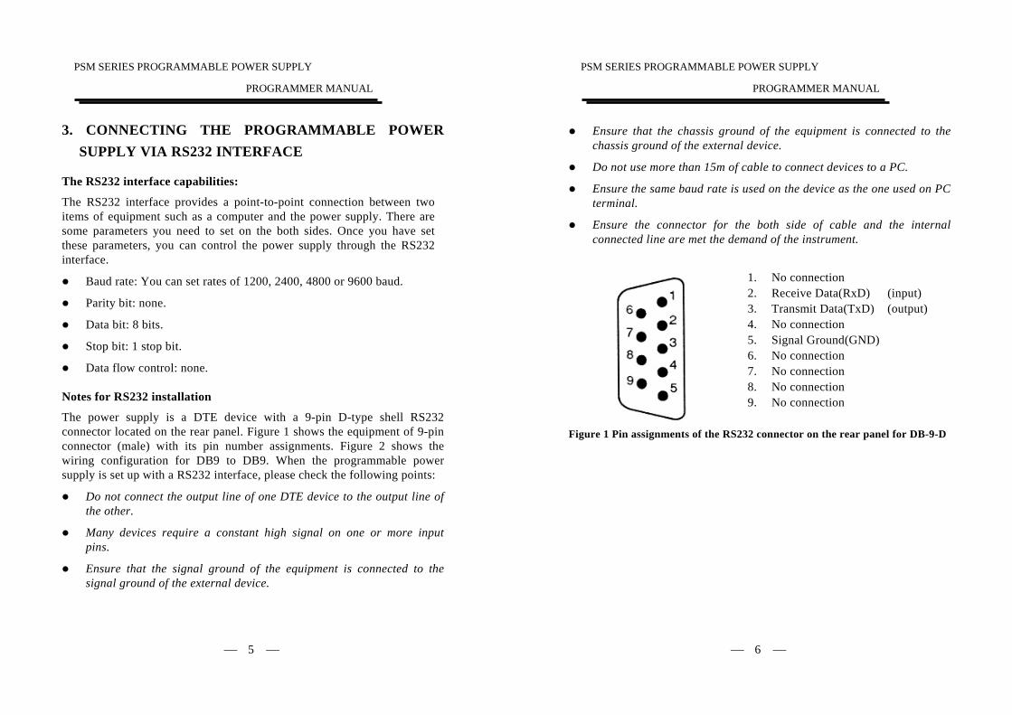
The power supply is a DTE device with a 9-pin D-type shell RS232 connector located on the rear panel. Figure 1 shows the equipment of 9-pin connector (male) with its pin number assignments. Figure 2 shows the wiring configuration for DB9 to DB9. When the programmable power supply is set up with a RS232 interface, please check the following points:
Do not connect the output line of one DTE device to the output line of the other.
Many devices require a constant high signal on one or more input pins.
Ensure that the signal ground of the equipment is connected to the signal ground of the external device.
PSM SERIES PROGRAMMABLE POWER SUPPLY
PROGRAMMER MANUAL
⎯ 6 ⎯
Ensure that the chassis ground of the equipment is connected to the chassis ground of the external device.
Do not use more than 15m of cable to connect devices to a PC.
Ensure the same baud rate is used on the device as the one used on PC terminal.
Ensure the connector for the both side of cable and the internal connected line are met the demand of the instrument.
1. No connection 2. Receive Data(RxD) (input) 3. Transmit Data(TxD) (output) 4. No connection 5. Signal Ground(GND) 6. No connection 7. No connection 8. No connection 9. No connection
Figure 1 Pin assignments of the RS232 connector on the rear panel for DB-9-D
PSM SERIES PROGRAMMABLE POWER SUPPLY
PROGRAMMER MANUAL
⎯ 7 ⎯
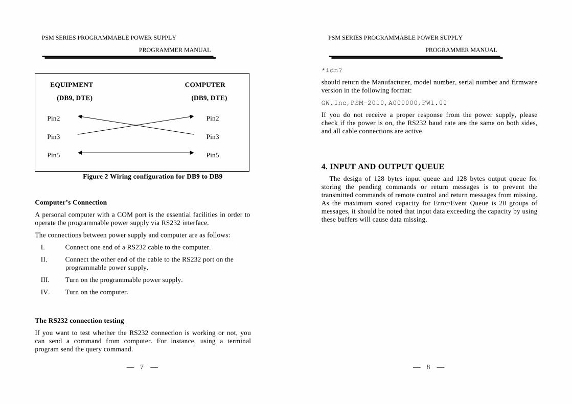
Figure 2 Wiring configuration for DB9 to DB9 Computer’s Connection
A personal computer with a COM port is the essential facilities in order to operate the programmable power supply via RS232 interface.
The connections between power supply and computer are as follows:
I. Connect one end of a RS232 cable to the computer.
II. Connect the other end of the cable to the RS232 port on the programmable power supply.
III. Turn on the programmable power supply.
IV. Turn on the computer.
The RS232 connection testing
If you want to test whether the RS232 connection is working or not, you can send a command from computer. For instance, using a terminal program send the query command.
EQUIPMENT
(DB9, DTE)
COMPUTER
(DB9, DTE)
Pin2
Pin3
Pin5 Pin5
Pin3
Pin2
PSM SERIES PROGRAMMABLE POWER SUPPLY
PROGRAMMER MANUAL
⎯ 8 ⎯
*idn?
should return the Manufacturer, model number, serial number and firmware version in the following format:
GW.Inc,PSM-2010,A000000,FW1.00
If you do not receive a proper response from the power supply, please check if the power is on, the RS232 baud rate are the same on both sides, and all cable connections are active.
4. INPUT AND OUTPUT QUEUE The design of 128 bytes input queue and 128 bytes output queue for
storing the pending commands or return messages is to prevent the transmitted commands of remote control and return messages from missing. As the maximum stored capacity for Error/Event Queue is 20 groups of messages, it should be noted that input data exceeding the capacity by using these buffers will cause data missing.
PSM SERIES PROGRAMMABLE POWER SUPPLY
PROGRAMMER MANUAL
⎯ 9 ⎯
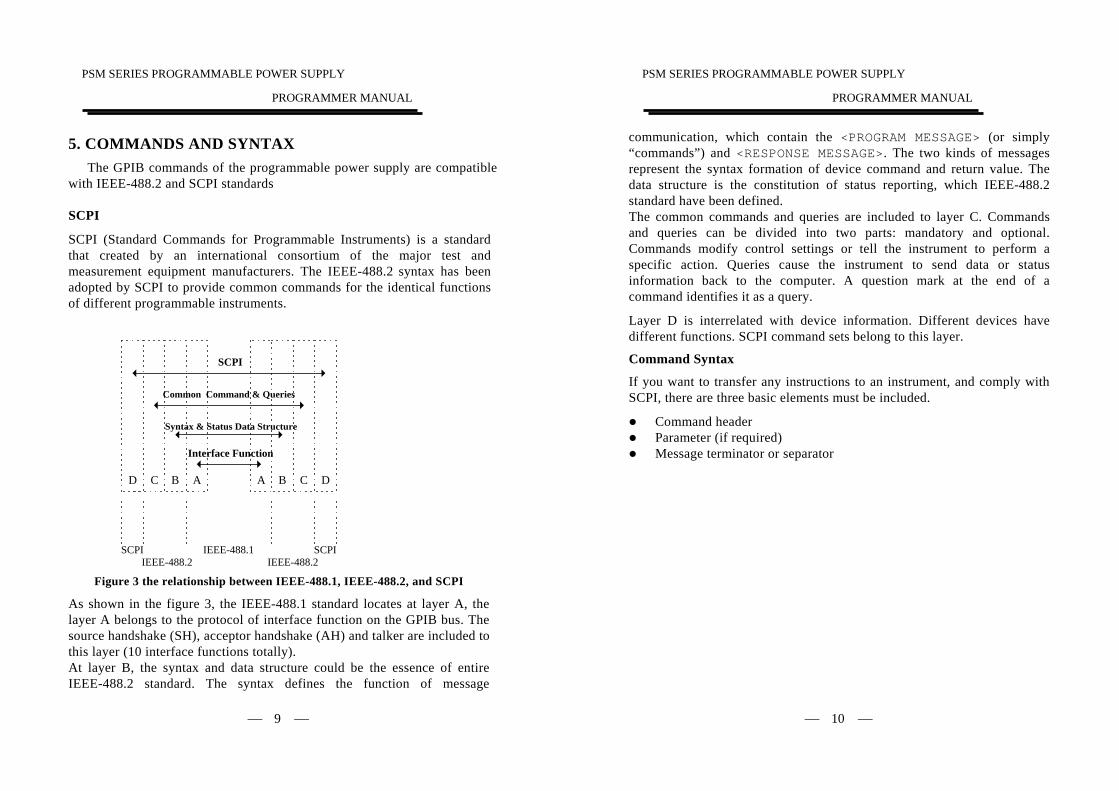
5. COMMANDS AND SYNTAX The GPIB commands of the programmable power supply are compatible
with IEEE-488.2 and SCPI standards
SCPI
SCPI (Standard Commands for Programmable Instruments) is a standard that created by an international consortium of the major test and measurement equipment manufacturers. The IEEE-488.2 syntax has been adopted by SCPI to provide common commands for the identical functions of different programmable instruments.
Figure 3 the relationship between IEEE-488.1, IEEE-488.2, and SCPI
As shown in the figure 3, the IEEE-488.1 standard locates at layer A, the layer A belongs to the protocol of interface function on the GPIB bus. The source handshake (SH), acceptor handshake (AH) and talker are included to this layer (10 interface functions totally). At layer B, the syntax and data structure could be the essence of entire IEEE-488.2 standard. The syntax defines the function of message
SCPIIEEE-488.2 IEEE-488.2
SCPIIEEE-488.1
A AB B CC DD
Interface Function
Syntax & Status Data Structure
Common Command & Queries
SCPI
PSM SERIES PROGRAMMABLE POWER SUPPLY
PROGRAMMER MANUAL
⎯ 10 ⎯
communication, which contain the <PROGRAM MESSAGE> (or simply “commands”) and <RESPONSE MESSAGE>. The two kinds of messages represent the syntax formation of device command and return value. The data structure is the constitution of status reporting, which IEEE-488.2 standard have been defined. The common commands and queries are included to layer C. Commands and queries can be divided into two parts: mandatory and optional. Commands modify control settings or tell the instrument to perform a specific action. Queries cause the instrument to send data or status information back to the computer. A question mark at the end of a command identifies it as a query.
Layer D is interrelated with device information. Different devices have different functions. SCPI command sets belong to this layer.
Command Syntax
If you want to transfer any instructions to an instrument, and comply with SCPI, there are three basic elements must be included.
Command header Parameter (if required) Message terminator or separator
PSM SERIES PROGRAMMABLE POWER SUPPLY
PROGRAMMER MANUAL
⎯ 11 ⎯
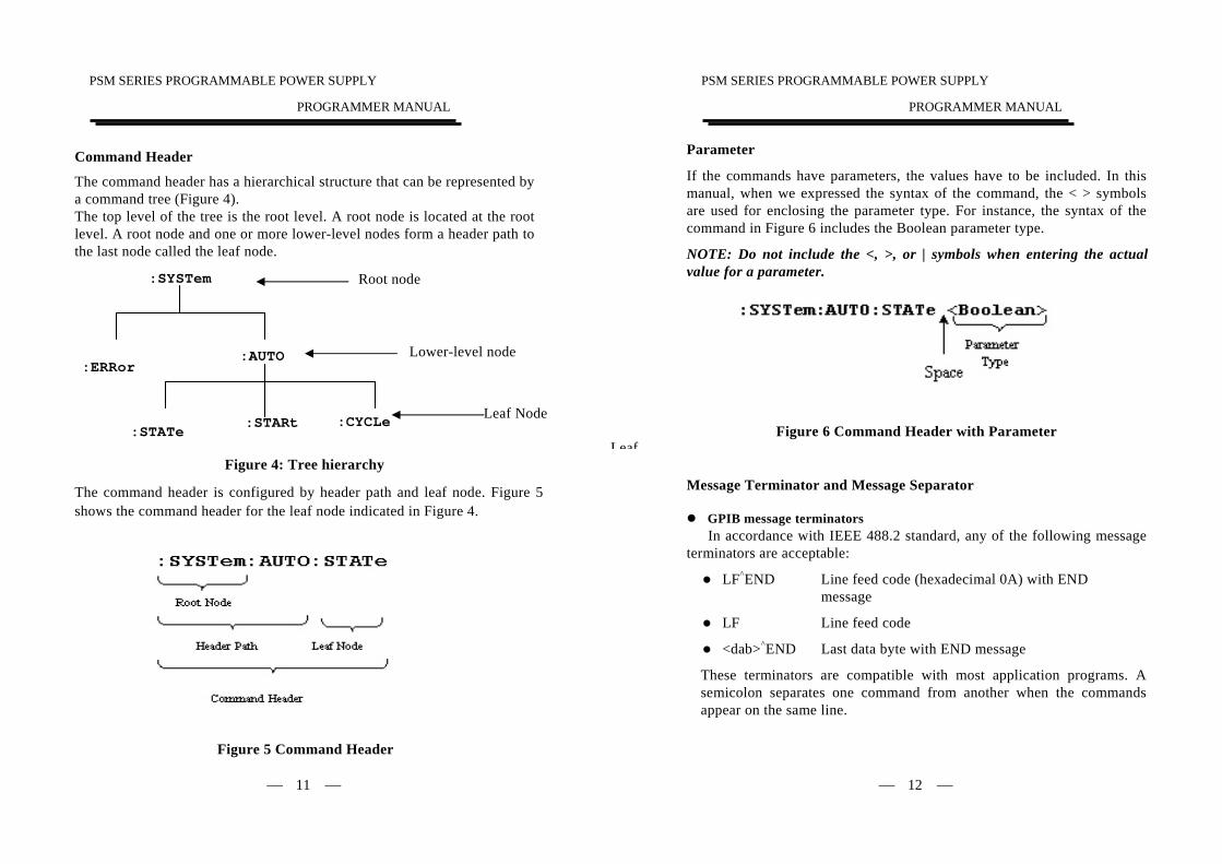
Leaf Node
Command Header
The command header has a hierarchical structure that can be represented by a command tree (Figure 4). The top level of the tree is the root level. A root node is located at the root level. A root node and one or more lower-level nodes form a header path to the last node called the leaf node.
Figure 4: Tree hierarchy
The command header is configured by header path and leaf node. Figure 5 shows the command header for the leaf node indicated in Figure 4.
Figure 5 Command Header
Leaf
:SYSTem Root node
:ERRor
:STATe
:AUTO
:STARt :CYCLe
Lower-level node
PSM SERIES PROGRAMMABLE POWER SUPPLY
PROGRAMMER MANUAL
⎯ 12 ⎯
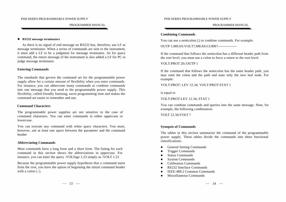
Parameter
If the commands have parameters, the values have to be included. In this manual, when we expressed the syntax of the command, the < > symbols are used for enclosing the parameter type. For instance, the syntax of the command in Figure 6 includes the Boolean parameter type.
NOTE: Do not include the <, >, or | symbols when entering the actual value for a parameter.
Figure 6 Command Header with Parameter
Message Terminator and Message Separator
GPIB message terminators In accordance with IEEE 488.2 standard, any of the following message
terminators are acceptable:
LF^END Line feed code (hexadecimal 0A) with END message
LF Line feed code
<dab>^END Last data byte with END message
These terminators are compatible with most application programs. A semicolon separates one command from another when the commands appear on the same line.
PSM SERIES PROGRAMMABLE POWER SUPPLY
PROGRAMMER MANUAL
⎯ 13 ⎯
RS232 message terminators
As there is no signal of end message on RS232 bus, therefore, use LF as message terminator. When a series of commands are sent to the instrument, it must add a LF to be a judgment for message terminator. As for query command, the return message of the instrument is also added a LF for PC to judge message terminator.
Entering Commands
The standards that govern the command set for the programmable power supply allow for a certain amount of flexibility when you enter commands. For instance, you can abbreviate many commands or combine commands into one message that you send to the programmable power supply. This flexibility, called friendly listening, saves programming time and makes the command set easier to remember and use.
Command Characters
The programmable power supplies are not sensitive to the case of command characters. You can enter commands in either uppercase or lowercase.
You can execute any command with white space characters. You must, however, use at least one space between the parameter and the command header
Abbreviating Commands
Most commands have a long form and a short form. The listing for each command in this section shows the abbreviations in uppercase. For instance, you can enter the query :VOLTage 1.23 simply as :VOLT 1.23
Because the programmable power supply hypothesis that a command starts from the root, you have the option of beginning the initial command header with a colon (:).
PSM SERIES PROGRAMMABLE POWER SUPPLY
PROGRAMMER MANUAL
⎯ 14 ⎯
Combining Commands
You can use a semicolon (;) to combine commands. For example:
OUTP 1;MEAS:VOLT?;MEAS:CURR?----------------
If the command that follows the semicolon has a different header path from the root level, you must use a colon to force a return to the root level:
VOLT:PROT 20;:OUTP 1
If the command that follows the semicolon has the same header path, you may omit the colon and the path and state only the new leaf node. For example:
VOLT:PROT: LEV 12.34; VOLT:PROT:STAT 1
is equal to
VOLT:PROT:LEV 12.34; STAT 1
You can combine commands and queries into the same message. Note, for example, the following combination:
VOLT 12.34;VOLT ?
Synopsis of Commands
The tables in this section summarize the command of the programmable power supply. These tables divide the commands into three functional classifications:
General Setting Commands Trigger Commands Status Commands System Commands Calibration Commands RS232 Interface Commands IEEE-488.2 Common Commands Miscellaneous Commands
PSM SERIES PROGRAMMABLE POWER SUPPLY
PROGRAMMER MANUAL
⎯ 15 ⎯
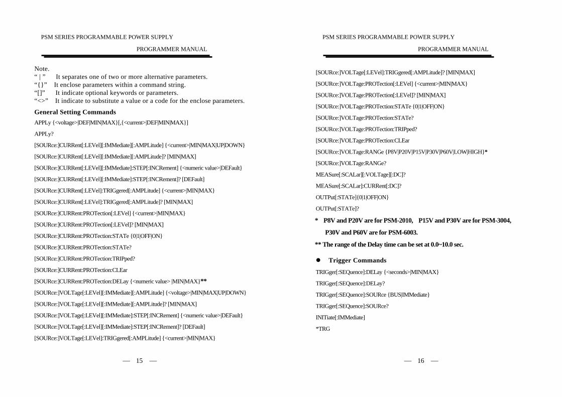
Note. “ | ” It separates one of two or more alternative parameters. “{}” It enclose parameters within a command string. “[]” It indicate optional keywords or parameters. “<>” It indicate to substitute a value or a code for the enclose parameters.
General Setting Commands APPLy {<voltage>|DEF|MIN|MAX}[,{<current>|DEF|MIN|MAX}]
APPLy?
[SOURce:]CURRent[:LEVel][:IMMediate][:AMPLitude] {<current>|MIN|MAX|UP|DOWN}
[SOURce:]CURRent[:LEVel][:IMMediate][:AMPLitude]? [MIN|MAX]
[SOURce:]CURRent[:LEVel][:IMMediate]:STEP[:INCRement] {<numeric value>|DEFault}
[SOURce:]CURRent[:LEVel][:IMMediate]:STEP[:INCRement]? [DEFault]
[SOURce:]CURRent[:LEVel]:TRIGgered[:AMPLitude] {<current>|MIN|MAX}
[SOURce:]CURRent[:LEVel]:TRIGgered[:AMPLitude]? [MIN|MAX]
[SOURce:]CURRent:PROTection[:LEVel] {<current>|MIN|MAX}
[SOURce:]CURRent:PROTection[:LEVel]? [MIN|MAX]
[SOURce:]CURRent:PROTection:STATe {0|1|OFF|ON}
[SOURce:]CURRent:PROTection:STATe?
[SOURce:]CURRent:PROTection:TRIPped?
[SOURce:]CURRent:PROTection:CLEar
[SOURce:]CURRent:PROTection:DELay {<numeric value> |MIN|MAX}**
[SOURce:]VOLTage[:LEVel][:IMMediate][:AMPLitude] {<voltage>|MIN|MAX|UP|DOWN}
[SOURce:]VOLTage[:LEVel][:IMMediate][:AMPLitude]? [MIN|MAX]
[SOURce:]VOLTage[:LEVel][:IMMediate]:STEP[:INCRement] {<numeric value>|DEFault}
[SOURce:]VOLTage[:LEVel][:IMMediate]:STEP[:INCRement]? [DEFault]
[SOURce:]VOLTage[:LEVel]:TRIGgered[:AMPLitude] {<current>|MIN|MAX}
PSM SERIES PROGRAMMABLE POWER SUPPLY
PROGRAMMER MANUAL
⎯ 16 ⎯
[SOURce:]VOLTage[:LEVel]:TRIGgered[:AMPLitude]? [MIN|MAX]
[SOURce:]VOLTage:PROTection[:LEVel] {<current>|MIN|MAX}
[SOURce:]VOLTage:PROTection[:LEVel]? [MIN|MAX]
[SOURce:]VOLTage:PROTection:STATe {0|1|OFF|ON}
[SOURce:]VOLTage:PROTection:STATe?
[SOURce:]VOLTage:PROTection:TRIPped?
[SOURce:]VOLTage:PROTection:CLEar
[SOURce:]VOLTage:RANGe {P8V|P20V|P15V|P30V|P60V|LOW|HIGH}*
[SOURce:]VOLTage:RANGe?
MEASure[:SCALar][:VOLTage][:DC]?
MEASure[:SCALar]:CURRent[:DC]?
OUTPut[:STATe]{0|1|OFF|ON}
OUTPut[:STATe]?
* P8V and P20V are for PSM-2010, P15V and P30V are for PSM-3004,
P30V and P60V are for PSM-6003.
** The range of the Delay time can be set at 0.0~10.0 sec.
Trigger Commands
TRIGger[:SEQuence]:DELay {<seconds>|MIN|MAX}
TRIGger[:SEQuence]:DELay?
TRIGger[:SEQuence]:SOURce {BUS|IMMediate}
TRIGger[:SEQuence]:SOURce?
INITiate[:IMMediate]
*TRG
PSM SERIES PROGRAMMABLE POWER SUPPLY
PROGRAMMER MANUAL
⎯ 17 ⎯
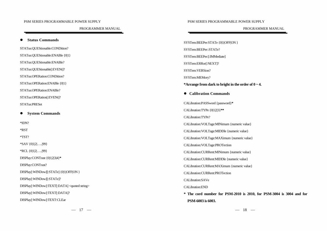
Status Commands
STATus:QUEStionable:CONDition?
STATus:QUEStionable:ENABle {0|1}
STATus:QUEStionable:ENABle?
STATus:QUEStionable[:EVENt]?
STATus:OPERation:CONDition?
STATus:OPERation:ENABle {0|1}
STATus:OPERation:ENABle?
STATus:OPERation[:EVENt]?
STATus:PRESet
System Commands
*IDN?
*RST
*TST?
*SAV {0|1|2|…..|99}
*RCL {0|1|2|…..|99}
DISPlay:CONTrast {0|1|2|3|4}*
DISPlay:CONTrast?
DISPlay[:WINDow][:STATe] {0|1|OFF|ON }
DISPlay[:WINDow][:STATe]?
DISPlay[:WINDow]:TEXT[:DATA] <quoted string>
DISPlay[:WINDow]:TEXT[:DATA]?
DISPlay[:WINDow]:TEXT:CLEar
PSM SERIES PROGRAMMABLE POWER SUPPLY
PROGRAMMER MANUAL
⎯ 18 ⎯
SYSTem:BEEPer:STATe {0|1|OFF|ON }
SYSTem:BEEPer::STATe?
SYSTem:BEEPer:[:IMMediate]
SYSTem:ERRor[:NEXT]?
SYSTem:VERSion?
SYSTem:MEMory?
*Arrange from dark to bright in the order of 0 ~ 4.
Calibration Commands
CALibration:PASSword {password}*
CALibration:TYPe {0|1|2|3}**
CALibration:TYPe?
CALibration:VOLTage:MINimum {numeric value}
CALibration:VOLTage:MIDDle {numeric value}
CALibration:VOLTage:MAXimum {numeric value}
CALibration:VOLTage:PROTection
CALibration:CURRent:MINimum {numeric value}
CALibration:CURRent:MIDDle {numeric value}
CALibration:CURRent:MAXimum {numeric value}
CALibration:CURRent:PROTection
CALibration:SAVe
CALibration:END
* The cord number for PSM-2010 is 2010, for PSM-3004 is 3004 and for
PSM-6003 is 6003.
PSM SERIES PROGRAMMABLE POWER SUPPLY
PROGRAMMER MANUAL
⎯ 19 ⎯
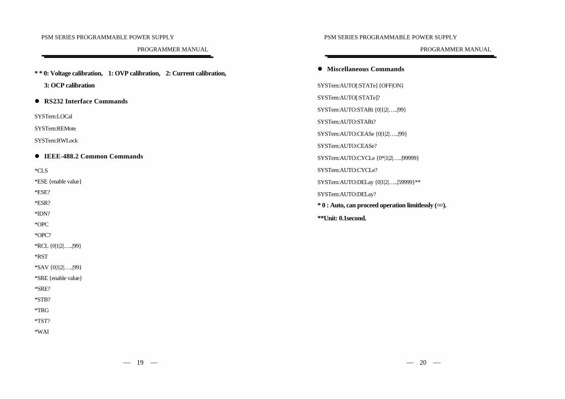
* * 0: Voltage calibration, 1: OVP calibration, 2: Current calibration,
3: OCP calibration
RS232 Interface Commands
SYSTem:LOCal
SYSTem:REMote
SYSTem:RWLock
IEEE-488.2 Common Commands
*CLS
*ESE {enable value}
*ESE?
*ESR?
*IDN?
*OPC
*OPC?
*RCL {0|1|2|…..|99}
*RST
*SAV {0|1|2|…..|99}
*SRE {enable value}
*SRE?
*STB?
*TRG
*TST?
*WAI
PSM SERIES PROGRAMMABLE POWER SUPPLY
PROGRAMMER MANUAL
⎯ 20 ⎯
Miscellaneous Commands
SYSTem:AUTO[:STATe] {OFF|ON}
SYSTem:AUTO[:STATe]?
SYSTem:AUTO:STARt {0|1|2|…..|99}
SYSTem:AUTO:STARt?
SYSTem:AUTO:CEASe {0|1|2|…..|99}
SYSTem:AUTO:CEASe?
SYSTem:AUTO:CYCLe {0*|1|2|…..|99999}
SYSTem:AUTO:CYCLe?
SYSTem:AUTO:DELay {0|1|2|…..|59999}**
SYSTem:AUTO:DELay?
* 0 : Auto, can proceed operation limitlessly (∞).
**Unit: 0.1second.
PSM SERIES PROGRAMMABLE POWER SUPPLY
PROGRAMMER MANUAL
⎯ 21 ⎯
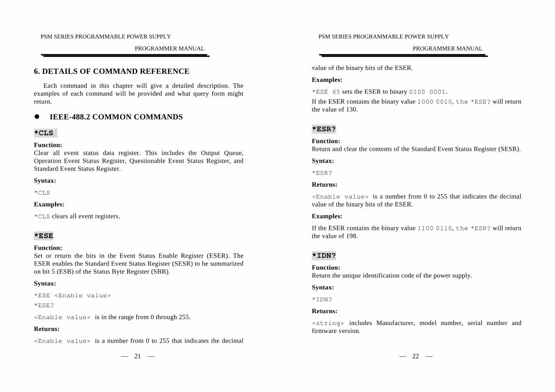
6. DETAILS OF COMMAND REFERENCE
Each command in this chapter will give a detailed description. The examples of each command will be provided and what query form might return.
IEEE-488.2 COMMON COMMANDS
*CLS Function: Clear all event status data register. This includes the Output Queue, Operation Event Status Register, Questionable Event Status Register, and Standard Event Status Register.
Syntax:
*CLS
Examples:
*CLS clears all event registers.
*ESE
Function: Set or return the bits in the Event Status Enable Register (ESER). The ESER enables the Standard Event Status Register (SESR) to be summarized on bit 5 (ESB) of the Status Byte Register (SBR).
Syntax:
*ESE <Enable value>
*ESE?
<Enable value> is in the range from 0 through 255.
Returns:
<Enable value> is a number from 0 to 255 that indicates the decimal
PSM SERIES PROGRAMMABLE POWER SUPPLY
PROGRAMMER MANUAL
⎯ 22 ⎯
value of the binary bits of the ESER.
Examples:
*ESE 65 sets the ESER to binary 0100 0001. If the ESER contains the binary value 1000 0010, the *ESE? will return the value of 130.
*ESR? Function: Return and clear the contents of the Standard Event Status Register (SESR).
Syntax:
*ESR?
Returns:
<Enable value> is a number from 0 to 255 that indicates the decimal value of the binary bits of the ESER.
Examples:
If the ESER contains the binary value 1100 0110, the *ESR? will return the value of 198.
*IDN? Function: Return the unique identification code of the power supply.
Syntax:
*IDN?
Returns:
<string> includes Manufacturer, model number, serial number and firmware version.
PSM SERIES PROGRAMMABLE POWER SUPPLY
PROGRAMMER MANUAL
⎯ 23 ⎯
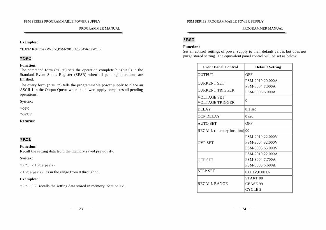
Examples:
*IDN? Returns GW.Inc,PSM-2010,A1234567,FW1.00 *OPC
Function: The command form (*OPC) sets the operation complete bit (bit 0) in the Standard Event Status Register (SESR) when all pending operations are finished. The query form (*OPC?) tells the programmable power supply to place an ASCII 1 in the Output Queue when the power supply completes all pending operations.
Syntax:
*OPC
*OPC?
Returns:
1
*RCL
Function: Recall the setting data from the memory saved previously.
Syntax:
*RCL <Integers>
<Integers> is in the range from 0 through 99.
Examples:
*RCL 12 recalls the setting data stored in memory location 12.
PSM SERIES PROGRAMMABLE POWER SUPPLY
PROGRAMMER MANUAL
⎯ 24 ⎯
*RST Function: Set all control settings of power supply to their default values but does not purge stored setting. The equivalent panel control will be set as below:
Front Panel Control Default Setting
OUTPUT OFF
CURRENT SET
CURRENT TRIGGER
PSM-2010:20.000A PSM-3004:7.000A PSM-6003:6.000A
VOLTAGE SET VOLTAGE TRIGGER 0
DELAY 0.1 sec
OCP DELAY 0 sec
AUTO SET OFF
RECALL (memory location) 00
OVP SET PSM-2010:22.000V PSM-3004:32.000V PSM-6003:65.000V
OCP SET PSM-2010:22.000A PSM-3004:7.700A PSM-6003:6.600A
STEP SET 0.001V,0.001A
RECALL RANGE START 00 CEASE 99 CYCLE 2
PSM SERIES PROGRAMMABLE POWER SUPPLY
PROGRAMMER MANUAL
⎯ 25 ⎯
Syntax:
*RST
*SAV
Function: Save the setting data to a specific memory location.
Syntax:
*SAV <Integers>
<Integers> is in the range from 0 through 99.
Examples:
*SAV 01 saves the current setting data to memory location 1. *SRE
Function: Set the contents of the Service Request Enable Register (SRER). The query form returns the contents of the SRER. Bit 6 of the SRER is always zero. The bits on the SRER correspond to the bits on the SBR.
Syntax:
*SRE <Enable Value>
*SRE?
<Enable Value> is in the range from 0 through 255.
Returns:
<Integers> is in the range from 0 through 255.
Examples
*SRE 7 sets bits of the SRER to 0000 0111. If the *SRE? returns 3, the SRER is set to 0000 0011.
PSM SERIES PROGRAMMABLE POWER SUPPLY
PROGRAMMER MANUAL
⎯ 26 ⎯
*STB? Function: The query of the Status Byte register (SBR) with *STB? will return a decimal number representing the bits that are set (true) in the status register.
Syntax:
*STB?
Returns:
<Integers> is in the range from 0 through 255.
Examples: *STB? returns 81, if SBR contains the binary value 0101 0001. *TRG Function: When select bus as trigger source, this command will generates a trigger to the trigger subsystem.
Syntax:
*TRG
*PSC Function: Set or query the Power-on-Status-Clean-Flag.
Syntax:
*PSC {0|1}
*PSC?
Examples: *When PSC 1 is turned on, the SESER,SRER,OSER and QSER will be removed.
PSM SERIES PROGRAMMABLE POWER SUPPLY
PROGRAMMER MANUAL
⎯ 27 ⎯
*TST? Function: Self-test and test the RAM, ROM.
Syntax:
*TST?
Returns:
0|-300
Examples:
*TST? returns 0, if the test is successful. *TST? returns –300, if the test is unsuccessful. *WAI Function: WAI prevents the programming instrument from executing further commands or queries until all pending operations are finished.
Syntax:
*WAI
GENERAL SETTING COMMANDS :APPLy
Function: Set the output voltage and current value.
Syntax:
:APPLy {<Voltage>|DEF|MIN|MAX}[,{<Current>|DEF|MIN|MAX}]
:APPLy ?
PSM SERIES PROGRAMMABLE POWER SUPPLY
PROGRAMMER MANUAL
⎯ 28 ⎯
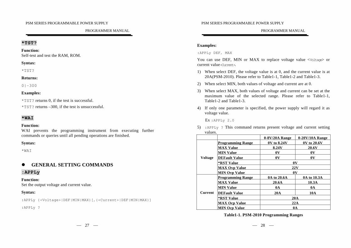
Examples:
:APPLy DEF, MAX
You can use DEF, MIN or MAX to replace voltage value <Voltage> or current value<Current>.
1) When select DEF, the voltage value is at 0, and the current value is at 20A(PSM-2010). Please refer to Table1-1, Table1-2 and Table1-3.
2) When select MIN, both values of voltage and current are at 0.
3) When select MAX, both values of voltage and current can be set at the maximum value of the selected range. Please refer to Table1-1, Table1-2 and Table1-3.
4) If only one parameter is specified, the power supply will regard it as voltage value.
Ex :APPLy 2.0
5) :APPLy ? This command returns present voltage and current setting values.
0-8V/20A Range 0-20V/10A Range Programming Range 0V to 8.24V 0V to 20.6V MAX Value 8.24V 20.6V MIN Value 0V 0V DEFault Value 0V 0V *RST Value 0V MAX Ovp Value 22V
Voltage
MIN Ovp Value 0V Programming Range 0A to 20.6A 0A to 10.3A MAX Value 20.6A 10.3A MIN Value 0A 0A DEFault Value 20A 10A *RST Value 20A MAX Ocp Value 22A
Current
MIN Ocp Value 0A
Table1-1. PSM-2010 Programming Ranges
PSM SERIES PROGRAMMABLE POWER SUPPLY
PROGRAMMER MANUAL
⎯ 29 ⎯
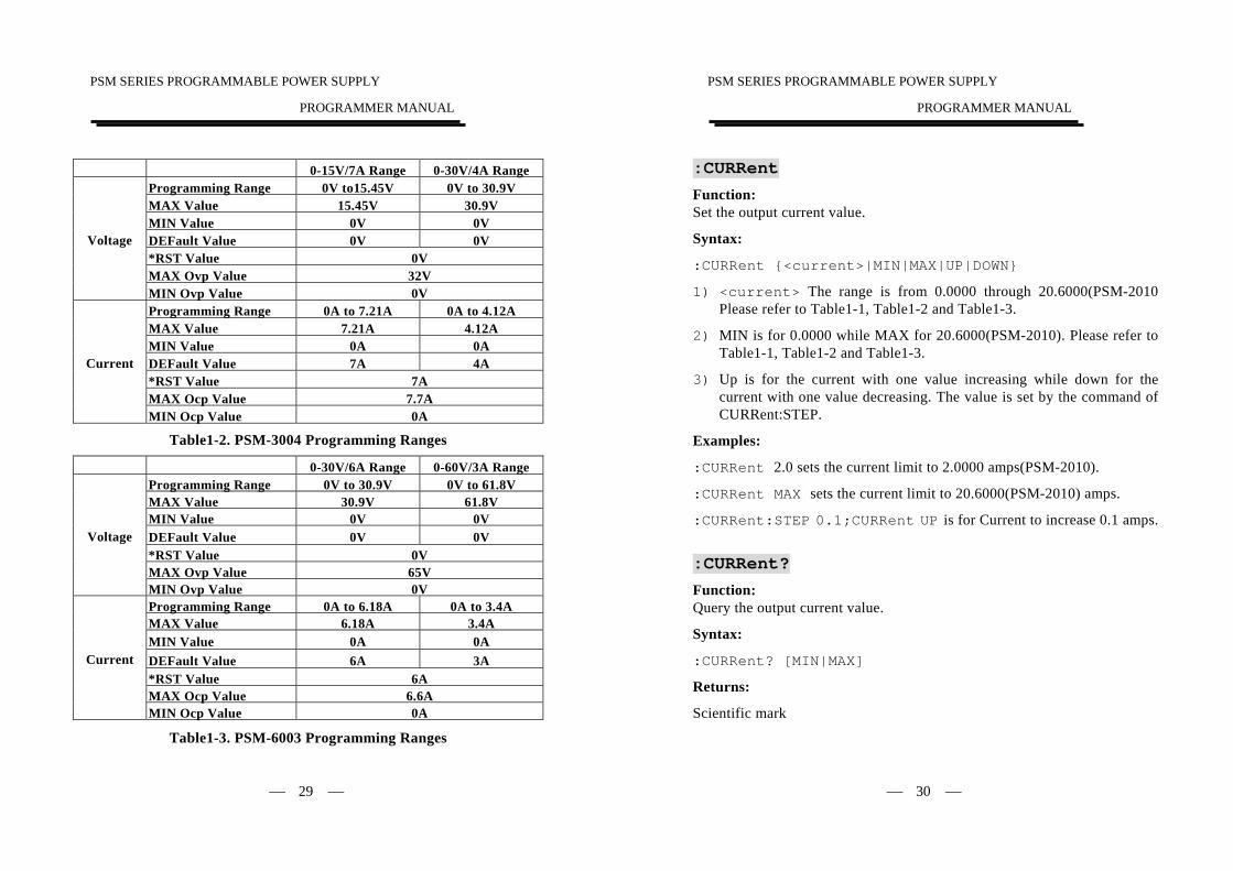
0-15V/7A Range 0-30V/4A Range
Programming Range 0V to15.45V 0V to 30.9V MAX Value 15.45V 30.9V MIN Value 0V 0V DEFault Value 0V 0V *RST Value 0V MAX Ovp Value 32V
Voltage
MIN Ovp Value 0V Programming Range 0A to 7.21A 0A to 4.12A MAX Value 7.21A 4.12A MIN Value 0A 0A DEFault Value 7A 4A *RST Value 7A MAX Ocp Value 7.7A
Current
MIN Ocp Value 0A
Table1-2. PSM-3004 Programming Ranges
0-30V/6A Range 0-60V/3A Range Programming Range 0V to 30.9V 0V to 61.8V MAX Value 30.9V 61.8V MIN Value 0V 0V DEFault Value 0V 0V *RST Value 0V MAX Ovp Value 65V
Voltage
MIN Ovp Value 0V Programming Range 0A to 6.18A 0A to 3.4A MAX Value 6.18A 3.4A MIN Value 0A 0A DEFault Value 6A 3A *RST Value 6A MAX Ocp Value 6.6A
Current
MIN Ocp Value 0A
Table1-3. PSM-6003 Programming Ranges
PSM SERIES PROGRAMMABLE POWER SUPPLY
PROGRAMMER MANUAL
⎯ 30 ⎯
:CURRent Function: Set the output current value.
Syntax:
:CURRent {<current>|MIN|MAX|UP|DOWN}
1) <current> The range is from 0.0000 through 20.6000(PSM-2010 Please refer to Table1-1, Table1-2 and Table1-3.
2) MIN is for 0.0000 while MAX for 20.6000(PSM-2010). Please refer to Table1-1, Table1-2 and Table1-3.
3) Up is for the current with one value increasing while down for the current with one value decreasing. The value is set by the command of CURRent:STEP.
Examples:
:CURRent 2.0 sets the current limit to 2.0000 amps(PSM-2010).
:CURRent MAX sets the current limit to 20.6000(PSM-2010) amps.
:CURRent:STEP 0.1;CURRent UP is for Current to increase 0.1 amps.
:CURRent? Function: Query the output current value.
Syntax:
:CURRent? [MIN|MAX]
Returns:
Scientific mark
PSM SERIES PROGRAMMABLE POWER SUPPLY
PROGRAMMER MANUAL
⎯ 31 ⎯
Examples:
:CURRent? returns +1.20000000E-02 if the current limit setting is 0.0120 amps(PSM-2010).
:CURRent? MIN returns +0.00000000E+00(PSM-2010)..
:CURRent? MAX returns +2.06000000E+01 (PSM-2010).
:VOLTage Function: Set the output voltage value.
Syntax:
:VOLTage {<voltage>|MIN|MAX|UP|DOWN}
1) <voltage> the range is from 0.0000 through 20.6000 (PSM-2010). Please refer to Table1-1, Table1-2 and Table1-3.
2) MIN is for 0.0000 while MAX for 20.6000(PSM-2010). Please refer to Table1-1, Table1-2 and Table1-3.
3) UP is for the voltage with one value increasing while down for the voltage with one value decreasing. The value is set by the command of VOLTage:STEP.
Examples:
:VOLTage 2.0 sets the voltage limit to 2.0000 volts (PSM-2010).
:VOLTage MAX sets the voltage limit to 20.6000 volts (PSM-2010).
:VOLTage:STEP 0.1;VOLTage UP is for Voltage to increase 0.1 volts.
:VOLTage? Function: Query the output voltage value.
PSM SERIES PROGRAMMABLE POWER SUPPLY
PROGRAMMER MANUAL
⎯ 32 ⎯
Syntax:
:VOLTage? [MIN|MAX]
Returns:
Scientific mark
Examples:
:VOLTage? returns +1.20000000E-02 if the voltage limit setting is 0.0120 volts(PSM-2010).
:VOLTage? MIN returns +0.00000000E+00(PSM-2010).
:VOLTage? MAX returns +2.06000000+01(PSM-2010).
:CURRent:STEP Function: Set or query the current step size.
Syntax:
:CURRent:STEP {<Decimal number>|DEFault}
:CURRent:STEP? [DEFault]
Examples:
1) :CURRent:STEP 1.0 sets the step size to 1.0A for current programming with the CURRent:UP and CURRent:DOWN command .The immediate current level increases or decreases by the value of the step size.
2) :CURRent:STEP DEF sets the step size to minimum resolution 0.5mA(PSM-2010).
3) :CURRent:STEP? returns the present current step size.
4) :CURRent:STEP? DEF returns the minimum resolution step size 0.5mA(PSM-2010).
PSM SERIES PROGRAMMABLE POWER SUPPLY
PROGRAMMER MANUAL
⎯ 33 ⎯
:VOLTage:STEP Function: Set or query the voltage step size.
Syntax:
:VOLTage:STEP {<Decimal number>|DEFault}
:VOLTage:STEP? [DEFault]
Examples:
1) :VOLTage:STEP 1.0 sets the step size to 1.0V for voltage programming with the VOLTage:UP and VOLTage:DOWN command .The immediate voltage level increases or decreases by the value of the step size.
2) :VOLTage:STEP DEF sets the step size to minimum resolution 0.5mV(PSM-2010).
3) :VOLTage:STEP? returns the present voltage step size.
4) :VOLTage:STEP? DEF returns the minimum resolution step size 0.5mV(PSM-2010).
:CURRent:TRIGgered Function: Set or query the triggered current level.
Syntax:
:CURRent:TRIGgered {<Decimal number>|MIN|MAX}
:CURRent:TRIGgered? [MIN|MAX]
Examples:
1) :CURRent:TRIGgered 1.0 sets the triggered current to 1.0000A(PSM-2010).
PSM SERIES PROGRAMMABLE POWER SUPPLY
PROGRAMMER MANUAL
⎯ 34 ⎯
2) :CURRent:TRIGgered MAX sets the triggered current to the highest programmable triggered current levels.
3) :CURRent:TRIGgered MIN sets the triggered current to 0.0000A(PSM-2010).
4) :CURRent:TRIGgered? returns the present triggered current level.
5) :CURRent:TRIGgered? MAX returns the highest programmable triggered current level.
6) :CURRent:TRIGgered? MIN returns the lowest programmable triggered current level.
:VOLTage:TRIGgered Function: Set or query the triggered voltage level.
Syntax:
:VOLTage:TRIGgered {<Decimal number>|MIN|MAX}
:VOLTage:TRIGgered? [MIN|MAX]
Examples:
1) :VOLTage:TRIGgered 1.0 sets the triggered voltage to 1.0000V(PSM-2010).
2) :VOLTage:TRIGgered MAX sets the triggered voltage to the highest programmable triggered voltage levels.
3) :VOLTage:TRIGgered MIN sets the triggered voltage to 0.0000V(PSM-2010).
4) :VOLTage:TRIGgered? returns the present triggered voltage level.
5) :VOLTage:TRIGgered? MAX returns the highest programmable triggered voltage level.
PSM SERIES PROGRAMMABLE POWER SUPPLY
PROGRAMMER MANUAL
⎯ 35 ⎯
6) :VOLTage:TRIGgered? MIN returns the lowest programmable triggered voltage level.
:MEASure:CURRent? Function: Read the actual output current.
Syntax:
:MEASure:CURRent?
Returns:
Scientific mark
Examples:
:MEASure:CURRent? might return +1.23400000E+00 to indicate that the load is drawing 1.2340 A(PSM-2010).
:MEASure? Function: Read the actual output voltage.
Syntax:
:MEASure?
Returns:
Scientific mark
Examples:
:MEASure? might return +1.15500000E+01 to indicate the voltage output is 11.5500V(PSM-2010).
PSM SERIES PROGRAMMABLE POWER SUPPLY
PROGRAMMER MANUAL
⎯ 36 ⎯
:CURRent:PROTection Function: Set the overcurrent protection value.
Syntax:
:PROTection:CURRent {<Decimal numbers>|MIN|MAX}
Examples:
:CURRent:PROTection 10 sets the overcurrent protection value to 10.000A(PSM-2010). :CURRent:PROTection MIN sets the overcurrent protection value to 0.000A(PSM-2010). :CURRent:PROTection MAX sets the overcurrent protection value to 22.000A(PSM-2010). Please refer to Table1-1, Table1-2 and Table1-3. :CURRent:PROTection? Function: Query the overcurrent protection value.
Syntax:
:CURRent:PROTection? [MIN|MAX]
Returns:
Scientific mark
Examples:
:CURRent:PROTection? will return the overcurrent protection value.
:CURRent:PROTection? MIN will return 0. :CURRent:PROTection? MAX will return the highest programmable current values. Please refer to Table1-1, Table1-2 and Table1-3.
PSM SERIES PROGRAMMABLE POWER SUPPLY
PROGRAMMER MANUAL
⎯ 37 ⎯
:CURRent:PROTection:STATe Function: Set or query the overcurrent protection status.
Syntax:
:CURRent:PROTection:STATe {0|1|OFF|ON}
:CURRent:PROTection?
Examples:
:CURRent:PROTection:STATe 0 sets the over-current protection off. If the overcurrent protection setting is on, the command of CURRent:PROTection? will return the value of 1. :CURRent:PROTection:TRIPped? Function: Query if the overcurrent protection circuit is tripped.
Syntax:
:CURRent:PROTection:TRIPped?
Returns:
0|1
Examples: This command will returns “1” if the overcurrent protection is tripped and not cleared or “0” if not tripped. :CURRent:PROTection:DELay Function: Set the OCP delay value.
Syntax:
:CURRent:PROTection:DELay{<Decimal number>|MIN|MAX}
PSM SERIES PROGRAMMABLE POWER SUPPLY
PROGRAMMER MANUAL
⎯ 38 ⎯
Examples: :CURRent:PROTection:DELay 3 sets the OCP delay value to 3 sec. :CURRent:PROTection:DELay MIN sets the OCP delay value to 0.1 sec. :CURRent:PROTection:DELay MAX sets the OCP delay value to 10.0 sec. :CURRent:PROTection:DELay? Function: Query the OCP delay value.
Syntax:
:CURRent:PROTection:DELay?[MIN|MAX]
Return:
<Decimal number>
Examples: :CURRent:PROTection:DELay? will return the OCP value. :CURRent:PROTection:DELay? MIN will return 0.1 sec. :CURRent:PROTection:DELay? MAX will return 10.1 sec. :VOLTage:PROTection Function: Set the overvoltage protection value.
Syntax:
:PROTection:VOLTage {<Decimal numbers>|MIN|MAX}
Examples:
:VOLTage:PROTection 10 sets the overvoltage protection value to 10.000V(PSM-2010). :VOLTage:PROTection MIN sets the overvoltage protection value to 0.000V(PSM-2010).
PSM SERIES PROGRAMMABLE POWER SUPPLY
PROGRAMMER MANUAL
⎯ 39 ⎯
:VOLTage:PROTection MAX sets the overvoltage protection value to 22.000V(PSM-2010). Please refer to Table1-1, Table1-2 and Table1-3. :VOLTage:PROTection? Function: Query the overvoltage protection value.
Syntax:
:VOLTage:PROTection? [MIN|MAX]
Returns:
Scientific Mark
Examples:
:VOLTage:PROTection? will return the overvoltage protection value.
:VOLTage:PROTection? MIN will return 0.
:VOLTage:PROTection? MAX will return the highest programmable overvoltage values. Please refer to Table1-1, Table1-2 and Table1-3. :VOLTage:PROTection:STATe Function: Set or query the overvoltage protection status.
Syntax:
:VOLTage:PROTection:STATe {0|1|OFF|ON}
:VOLTage:PROTection?
Examples:
:VOLTage:PROTection:STATe 0 sets the overvoltage protection off. If the overvoltage protection setting is on, the command of VOLTage:PROTection? will return the value of 1.
PSM SERIES PROGRAMMABLE POWER SUPPLY
PROGRAMMER MANUAL
⎯ 40 ⎯
:VOLTage:PROTection:TRIPped? Function: Query if the overvoltage protection circuit is tripped.
Syntax:
:VOLTage:PROTection:TRIPped?
Returns:
0|1
Examples: This command will returns “1” if the overvoltage protection is tripped and not cleared or “0” if not tripped. :CURRent:PROTection:CLEar Function: Clear OCP status.
Syntax:
:CURRent:PROTection:CLEar
When the panel displays the protective message, no further setting can be accepted by the device. Uses this command to clear the displayed messages in order to execute further setting.
Examples:
:CURRent:PROTection:CLEar
:VOLTage:PROTection:CLEar Function: Clear OVP status.
Syntax:
:VOLTage:PROTection:CLEar
PSM SERIES PROGRAMMABLE POWER SUPPLY
PROGRAMMER MANUAL
⎯ 41 ⎯
When the panel displays the protective message, no further setting can be accepted by the device. Uses this command to clear the displayed messages in order to execute further setting.
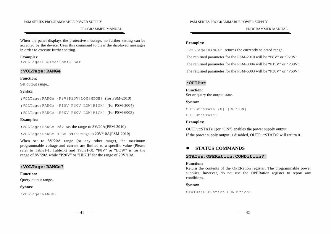
Examples: :VOLTage:PROTection:CLEar :VOLTage:RANGe Function: Set output range..
Syntax:
:VOLTage:RANGe {P8V|P20V|LOW|HIGH} (for PSM-2010)
:VOLTage:RANGe {P15V|P30V|LOW|HIGH} (for PSM-3004)
:VOLTage:RANGe {P30V|P60V|LOW|HIGH} (for PSM-6003)
Examples:
:VOLTage:RANGe P8V set the range to 8V/20A(PSM-2010)
:VOLTage:RANGe HIGH set the range to 20V/10A(PSM-2010)
When set to 8V/20A range (or any other range), the maximum programmable voltage and current are limited to a specific value (Please refer to Table1-1, Table1-2 and Table1-3). “P8V” or “LOW” is for the range of 8V/20A while “P20V” or ”HIGH” for the range of 20V/10A.
:VOLTage:RANGe? Function: Query output range..
Syntax:
:VOLTage:RANGe?
PSM SERIES PROGRAMMABLE POWER SUPPLY
PROGRAMMER MANUAL
⎯ 42 ⎯
Examples:
:VOLTage:RANGe? returns the currently selected range.
The returned parameter for the PSM-2010 will be “P8V” or “P20V”.
The returned parameter for the PSM-3004 will be “P15V” or “P30V”.
The returned parameter for the PSM-6003 will be “P30V” or “P60V”.
:OUTPut Function: Set or query the output state.
Syntax:
OUTPut:STATe {0|1|OFF|ON}
OUTPut:STATe?
Examples:
OUTPut:STATe 1(or “ON”) enables the power supply output. If the power supply output is disabled, OUTPut:STATe? will return 0.
STATUS COMMANDS
STATus:OPERation:CONDition? Function: Return the contents of the OPERation register. The programmable power supplies, however, do not use the OPERation register to report any conditions.
Syntax:
STATus:OPERation:CONDition?
PSM SERIES PROGRAMMABLE POWER SUPPLY
PROGRAMMER MANUAL
⎯ 43 ⎯
Returns
<Integers>
Examples:
STATus:OPERation:CONDition? returns 0. STATus:OPERation:ENABle Function: Set or query the enable mask that allows the masked conditions in the event register to be reported in the summary bit. If a bit is 1 (true) in the enable register and its associated event bit changes to 1 (true), the associated summary bit will change to 1 (true). Even though this is a 16-bit register, only 15 bits (bit 0 through bit 14) are used. Bit 15 always reads 0.
Syntax
STATus:OPERation:ENABle <Enable Value>
STATus:OPERation:ENABle?
<Enable Value> is an integer from 0 to 32767.
Returns
<Integers>
Examples
STATus:OPERation:ENABle 32767 sets all 15 bits of the register to 1. If the STATus:OPERation:ENABle? returns 0, all 15 bits of the register are 0. STATus:OPERation? Function: Returns and clears the contents of the OPERation register.
PSM SERIES PROGRAMMABLE POWER SUPPLY
PROGRAMMER MANUAL
⎯ 44 ⎯
Syntax:
STATus:OPERation?
Returns:
<Integers>
Examples:
STATus:OPERation? returns 0.
STATus:PRESet Function: Set the OPERation and QUESTionable enable registers to zeros.
Syntax:
STATus:PRESet
STATus:QUEStionable:CONDition? Function: Return the contents of the QUEStionable register. Reading the condition register is non-destructive.
Syntax:
STATus:QUEStionable:CONDition?
Returns:
<Integers>
Examples:
STATus:QUEStionable:CONDition? returns 0.
PSM SERIES PROGRAMMABLE POWER SUPPLY
PROGRAMMER MANUAL
⎯ 45 ⎯
STATus:QUEStionable:ENABle Function: Set or query the enable mask that allows the masked conditions in the event register to be reported in the summary bit. If a bit is 1 (true) in the enable register and its associated event bit changes to 1 (true), the associated summary bit will change to 1 (true). Even though this is a 16-bit register, only 15 bits (bit 0 through bit 14) are used. Bit 15 always reads 0.
Syntax:
STATus:QUEStionable:ENABle <Enable Value>
STATus:QUEStionable:ENABle?
<Enable Value> is an integer from 0 to 32767.
Returns:
<Integers>
Examples:
STATus:QUEStionable:ENABle 32767 sets all 15 bits of the register to 1. If the STATus:QUEStionable:ENABle? returns 0, all 15 bits of the register are 0. STATus:QUEStionable? Function: Return and clear the contents of the QUEStionable register. The response is a decimal value that summarizes the binary values of the set bits.
Syntax:
STATus:QUEStionable?
Returns:
<Integers>
PSM SERIES PROGRAMMABLE POWER SUPPLY
PROGRAMMER MANUAL
⎯ 46 ⎯
Examples:
STATus:QUEStionable? returns 0.
MISCELLANEOUS COMMANDS
SYSTem:AUTO:CYCLe Function: Set or query the number of times of execution.
Syntax:
SYSTem:AUTO:CYCLe <Integers>
SYSTem:AUTO:CYCLe?
<Integers> is in the range from 0 through 99999 or infinite.
Returns:
<Integers>
Examples:
SYSTem:AUTO:CYCLe 8 sets auto cycle on to repeat the setting 8 times.
SYSTem:AUTO:CYCLe 0 sets auto cycle on to repeat the setting infinite. If the command SYSTem:AUTO:CYCLe? Returns 0, means infinite. SYSTem:AUTO:DELay Function: Set the delay time under the current responding memory status.
Syntax:
SYSTem:AUTO:DELay <Integers>
SYSTem:AUTO:DELay?
<Integers> is in the range from 1 through 59999, its unit is 100ms.
PSM SERIES PROGRAMMABLE POWER SUPPLY
PROGRAMMER MANUAL
⎯ 47 ⎯
Returns:
<Integers>
Examples:
SYSTem:AUTO:DELay 1 sets auto delay time at 100ms for the memory of the specific section.
SYSTem:AUTO:DELay 1000 sets auto delay time at 100 seconds for the memory of the specific section, no further setting of auto delay will be done on next memory section until the previous auto delay is fulfilled. If the command SYSTem:AUTO:DELay? Returns 5, means delay 500ms at the current memory section that displayed on the panel. SYSTem:AUTO:CEASe Function: Set the end memory section for auto execute continuously.
Syntax:
SYSTem:AUTO:CEASe <Integers>
SYSTem:AUTO:CEASe?
<Integers> is in the range from 0 through 99 and must be large or equal to the value of START.
Returns:
<Integers>
Examples:
SYSTem:AUTO:CEASe 8 sets auto end on from the memory of location 8 of the current device. If the command SYSTem:AUTO:CEASe? Returns 99, means set the section 99 as the end.
PSM SERIES PROGRAMMABLE POWER SUPPLY
PROGRAMMER MANUAL
⎯ 48 ⎯
SYSTem:AUTO:STARt Function: Set the start memory section for auto execute continuously.
Syntax:
SYSTem:AUTO:STARt <Integers>
SYSTem:AUTO:STARt?
< Integers> is in the range from 0 through 99 and must be small or equal to the value of CEASE.
Returns:
<Integers>
Examples:
SYSTem:AUTO:STARt 0 sets auto start on from the memory of location 0 of the current device. If the command SYSTem:ATUO:STARt? Returns 2, means set the section 2 as the start. SYSTem:AUTO Function: Set or return automatic sequence setting.
Syntax:
SYSTem:AUTO:STATe {0|1|OFF|ON}
SYSTem:AUTO:STATe?
Returns:
0|1
Examples:
SYSTem:AUTO:STATe 1 sets auto sequence on.
PSM SERIES PROGRAMMABLE POWER SUPPLY
PROGRAMMER MANUAL
⎯ 49 ⎯
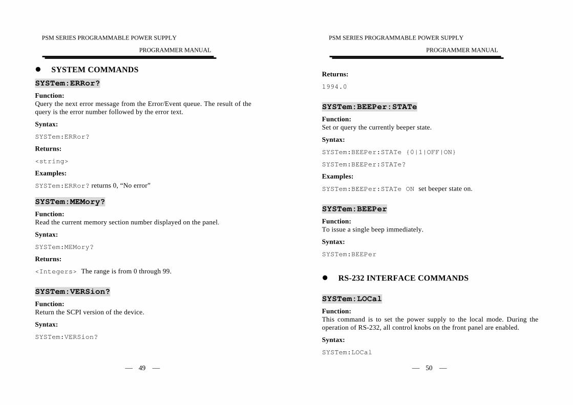
SYSTEM COMMANDS SYSTem:ERRor? Function: Query the next error message from the Error/Event queue. The result of the query is the error number followed by the error text.
Syntax:
SYSTem:ERRor?
Returns:
<string>
Examples:
SYSTem:ERRor? returns 0, “No error” SYSTem:MEMory? Function: Read the current memory section number displayed on the panel.
Syntax:
SYSTem:MEMory?
Returns:
<Integers> The range is from 0 through 99.
SYSTem:VERSion? Function: Return the SCPI version of the device.
Syntax:
SYSTem:VERSion?
PSM SERIES PROGRAMMABLE POWER SUPPLY
PROGRAMMER MANUAL
⎯ 50 ⎯
Returns:
1994.0
SYSTem:BEEPer:STATe Function: Set or query the currently beeper state.
Syntax:
SYSTem:BEEPer:STATe {0|1|OFF|ON}
SYSTem:BEEPer:STATe?
Examples:
SYSTem:BEEPer:STATe ON set beeper state on.
SYSTem:BEEPer Function: To issue a single beep immediately.
Syntax:
SYSTem:BEEPer
RS-232 INTERFACE COMMANDS SYSTem:LOCal Function: This command is to set the power supply to the local mode. During the operation of RS-232, all control knobs on the front panel are enabled.
Syntax:
SYSTem:LOCal
PSM SERIES PROGRAMMABLE POWER SUPPLY
PROGRAMMER MANUAL
⎯ 51 ⎯
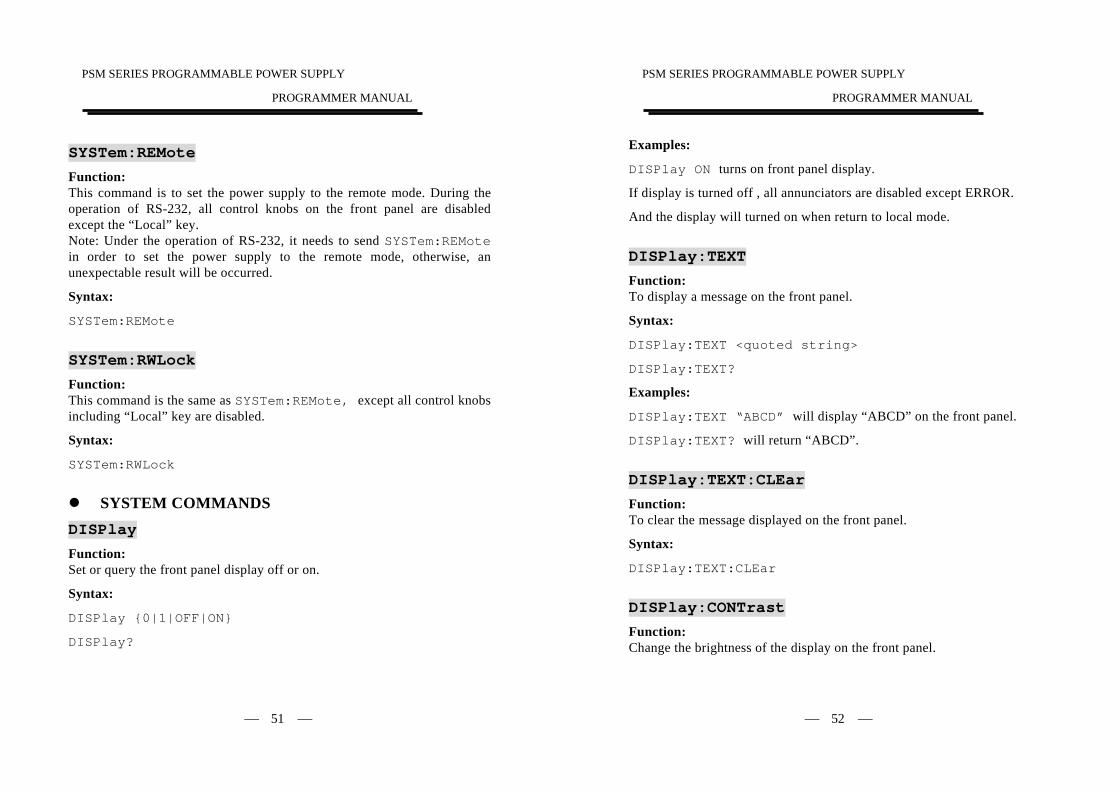
SYSTem:REMote Function: This command is to set the power supply to the remote mode. During the operation of RS-232, all control knobs on the front panel are disabled except the “Local” key. Note: Under the operation of RS-232, it needs to send SYSTem:REMote in order to set the power supply to the remote mode, otherwise, an unexpectable result will be occurred.
Syntax:
SYSTem:REMote
SYSTem:RWLock Function: This command is the same as SYSTem:REMote, except all control knobs including “Local” key are disabled.
Syntax:
SYSTem:RWLock
SYSTEM COMMANDS
DISPlay Function: Set or query the front panel display off or on.
Syntax:
DISPlay {0|1|OFF|ON}
DISPlay?
PSM SERIES PROGRAMMABLE POWER SUPPLY
PROGRAMMER MANUAL
⎯ 52 ⎯
Examples:
DISPlay ON turns on front panel display.
If display is turned off , all annunciators are disabled except ERROR.
And the display will turned on when return to local mode.
DISPlay:TEXT Function: To display a message on the front panel.
Syntax:
DISPlay:TEXT <quoted string>
DISPlay:TEXT?
Examples:
DISPlay:TEXT “ABCD” will display “ABCD” on the front panel.
DISPlay:TEXT? will return “ABCD”.
DISPlay:TEXT:CLEar Function: To clear the message displayed on the front panel.
Syntax:
DISPlay:TEXT:CLEar
DISPlay:CONTrast Function: Change the brightness of the display on the front panel.
PSM SERIES PROGRAMMABLE POWER SUPPLY
PROGRAMMER MANUAL
⎯ 53 ⎯
Syntax:
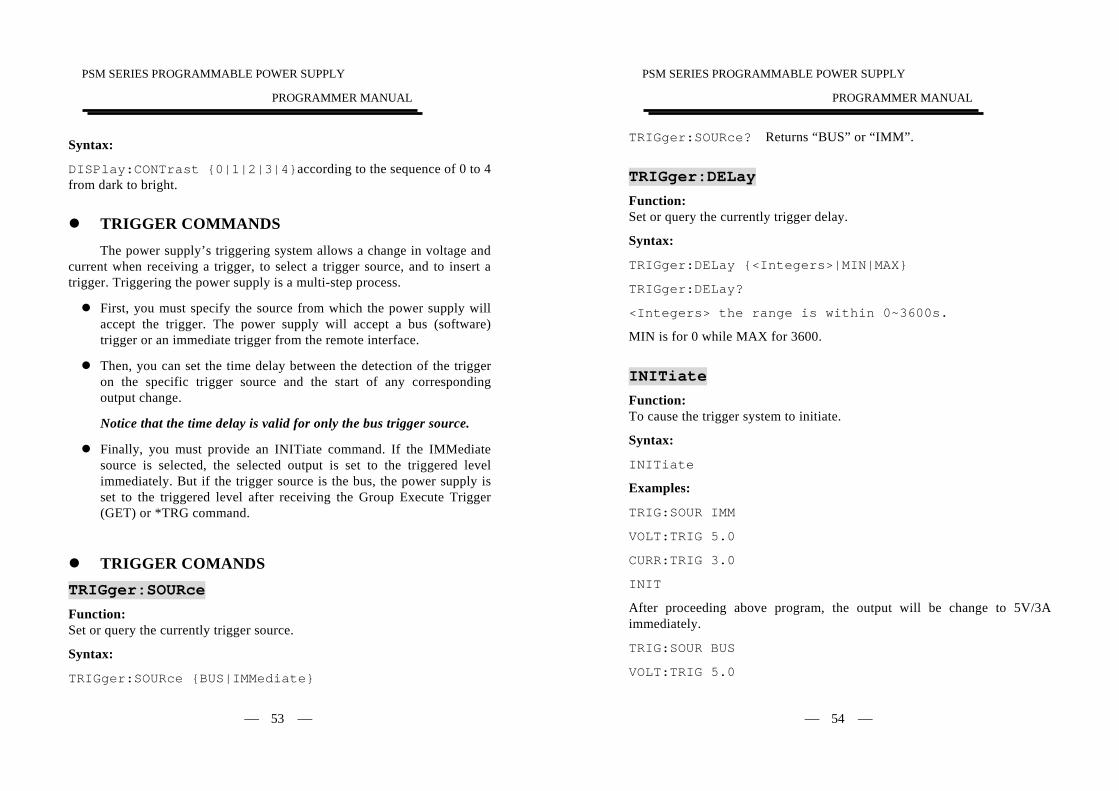
DISPlay:CONTrast {0|1|2|3|4}according to the sequence of 0 to 4 from dark to bright.
TRIGGER COMMANDS
The power supply’s triggering system allows a change in voltage and current when receiving a trigger, to select a trigger source, and to insert a trigger. Triggering the power supply is a multi-step process.
First, you must specify the source from which the power supply will accept the trigger. The power supply will accept a bus (software) trigger or an immediate trigger from the remote interface.
Then, you can set the time delay between the detection of the trigger on the specific trigger source and the start of any corresponding output change.
Notice that the time delay is valid for only the bus trigger source.
Finally, you must provide an INITiate command. If the IMMediate source is selected, the selected output is set to the triggered level immediately. But if the trigger source is the bus, the power supply is set to the triggered level after receiving the Group Execute Trigger (GET) or *TRG command.
TRIGGER COMANDS TRIGger:SOURce Function: Set or query the currently trigger source.
Syntax:
TRIGger:SOURce {BUS|IMMediate}
PSM SERIES PROGRAMMABLE POWER SUPPLY
PROGRAMMER MANUAL
⎯ 54 ⎯
TRIGger:SOURce? Returns “BUS” or “IMM”.
TRIGger:DELay Function: Set or query the currently trigger delay.
Syntax:
TRIGger:DELay {<Integers>|MIN|MAX}
TRIGger:DELay?
<Integers> the range is within 0~3600s.
MIN is for 0 while MAX for 3600.
INITiate Function: To cause the trigger system to initiate.
Syntax:
INITiate
Examples:
TRIG:SOUR IMM
VOLT:TRIG 5.0
CURR:TRIG 3.0
INIT
After proceeding above program, the output will be change to 5V/3A immediately.
TRIG:SOUR BUS
VOLT:TRIG 5.0
PSM SERIES PROGRAMMABLE POWER SUPPLY
PROGRAMMER MANUAL
⎯ 55 ⎯
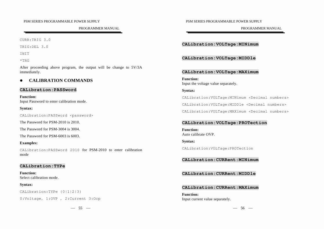
CURR:TRIG 3.0
TRIG:DEL 3.0
INIT
*TRG
After proceeding above program, the output will be change to 5V/3A immediately.
CALIBRATION COMMANDS
CALibration:PASSword Function: Input Password to enter calibration mode.
Syntax:
CALibration:PASSword <password>
The Password for PSM-2010 is 2010.
The Password for PSM-3004 is 3004.
The Password for PSM-6003 is 6003.
Examples:
CALibration:PASSword 2010 for PSM-2010 to enter calibration mode
CALibration:TYPe Function: Select calibration mode.
Syntax:
CALibration:TYPe {0|1|2|3}
0:Voltage, 1:OVP , 2:Current 3:Ocp
PSM SERIES PROGRAMMABLE POWER SUPPLY
PROGRAMMER MANUAL
⎯ 56 ⎯
CALibration:VOLTage:MINimum
CALibration:VOLTage:MIDDle
CALibration:VOLTage:MAXimum Function: Input the voltage value separately.
Syntax:
CALibration:VOLTage:MINimum <Decimal numbers>
CALibration:VOLTage:MIDDle <Decimal numbers>
CALibration:VOLTage:MAXimum <Decimal numbers>
CALibration:VOLTage:PROTection Function: Auto calibrate OVP.
Syntax:
CALibration:VOLTage:PROTection
CALibration:CURRent:MINimum
CALibration:CURRent:MIDDle
CALibration:CURRent:MAXimum Function: Input current value separately.
PSM SERIES PROGRAMMABLE POWER SUPPLY
PROGRAMMER MANUAL
⎯ 57 ⎯
Syntax:
CALibration:CURRent:MINimum <Decimal numbers>
CALibration:CURRent:MIDDle <Decimal numbers>
CALibration:CURRent:MAXimum <Decimal numbers>
CALibration:CURRent:PROTection Function: Auto calibrate OCP.
Syntax:
CALibration:CURRent:PROTection
CALibration:SAVe Function: To leave calibration mode after save.
Syntax:
CALibration:SAVe
CALibration:END Function: To leave calibration mode without saving.
Syntax:
CALibration:END
Note:
1) General calibration procedure:
Input Password to enter calibration mode, send command CALibration:TYPe 0, then according to the value measured with
PSM SERIES PROGRAMMABLE POWER SUPPLY
PROGRAMMER MANUAL
⎯ 58 ⎯
voltage meter, use the commands of
CALibration:VOLTage:MINimum<measured value>, CALibration:VOLTage:MIDDle < measured value >, CALibration:VOLTage:MAXimum < measured value >
in sequence to complete the voltage calibration, then the program will select type 1 automatically, therefore, just send the command CALibration:VOLTage:PROTection directly, the OVP calibration will be done automatically.
The current and OCP calibration method is the same as above procedure. After calibration, send the command CALibration:SAVe to save the calibration value, then exit the calibration mode, or send the command CALibration:end not to save the calibration value and exit the calibration mode.
2) During calibrating, use the command CALibration:TYPe to select the calibration type, the same type can be calibrated repeatedly.
PSM SERIES PROGRAMMABLE POWER SUPPLY
PROGRAMMER MANUAL
⎯ 59 ⎯
7. STATUS AND ERROR REPORTING A set of status registers allows the user to quickly determine the power
supply’s internal processing status. The status register, as well as the status and event reporting system, adhere to SCPI recommendations.
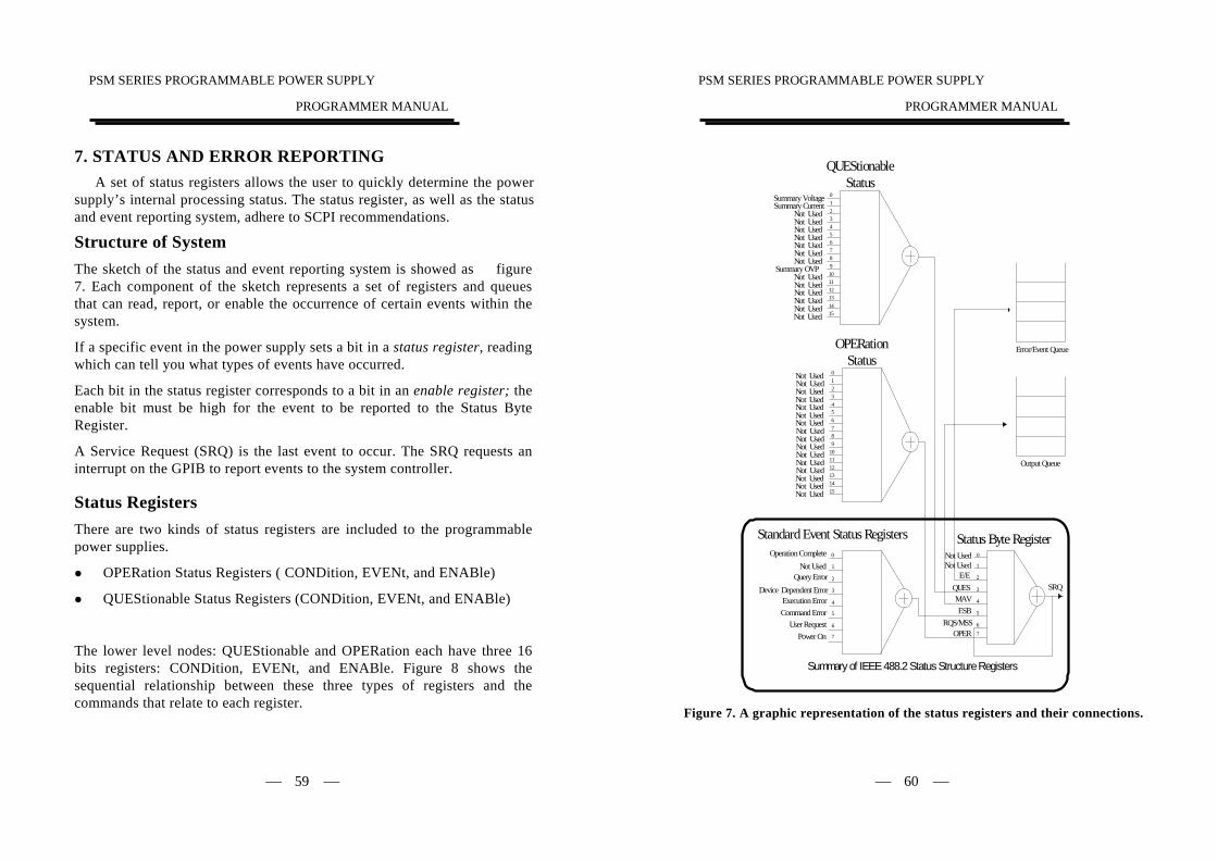
Structure of System The sketch of the status and event reporting system is showed as figure 7. Each component of the sketch represents a set of registers and queues that can read, report, or enable the occurrence of certain events within the system.
If a specific event in the power supply sets a bit in a status register, reading which can tell you what types of events have occurred.
Each bit in the status register corresponds to a bit in an enable register; the enable bit must be high for the event to be reported to the Status Byte Register.
A Service Request (SRQ) is the last event to occur. The SRQ requests an interrupt on the GPIB to report events to the system controller.
Status Registers There are two kinds of status registers are included to the programmable power supplies.
OPERation Status Registers ( CONDition, EVENt, and ENABle)
QUEStionable Status Registers (CONDition, EVENt, and ENABle)
The lower level nodes: QUEStionable and OPERation each have three 16 bits registers: CONDition, EVENt, and ENABle. Figure 8 shows the sequential relationship between these three types of registers and the commands that relate to each register.
PSM SERIES PROGRAMMABLE POWER SUPPLY
PROGRAMMER MANUAL
⎯ 60 ⎯
Not Used
Not UsedNot UsedNot UsedNot UsedNot Used
Summary OVPNot UsedNot UsedNot Used
Not UsedNot UsedNot Used
Not Used
Summary VoltageSummary Current
QUEStionableStatus
0123
9
151413121110
87654
Not Used
Not UsedNot Used
Not Used
Not UsedNot UsedNot Used
Not Used
OPERationStatus
Not Used23
01
1413121110987654
15
Command Error
Power OnUser Request
Execution ErrorDevice Dependent Error
Query ErrorNot Used
Standard Event Status RegistersOperation Complete
ESBRQS/MSS
MAV
Not Used
Status Byte RegisterNot Used
Summary of IEEE 488.2 Status Structure Registers
2
3
0
1
7
6
5
4
2
3
0
1
76
5
4
E/E
Not Used
Not UsedNot UsedNot UsedNot UsedNot UsedNot Used
QUES
OPER
SRQ
Error/Event Queue
Output Queue
Figure 7. A graphic representation of the status registers and their connections.

PSM SERIES PROGRAMMABLE POWER SUPPLY
PROGRAMMER MANUAL
⎯ 61 ⎯
Figure 8: Status registers and related commands
The CONDition register is a read-only register which monitors the present state of the instrument. The CONDition register updates in real time and the inputs are not latched or buffered. When a condition monitored by the CONDition register becomes true, the bit for that condition also becomes true (1). When the condition is false, the bit is 0. The read-only EVENt register latches any false-to-true change in condition. Once the bit in the EVENt register is set, it is no longer affected by changes in the corresponding bit of the CONDition register. The bit remains set until the controller reads it. The command *CLS (Clear Status) clears the EVENt register. QUEStionable Status Registers.
Table 4 shows the bit designations of the 16 bit QUEStionable Status Register.
EnableRegister
EventRegister
ConditionRegister
To SBR
PSM SERIES PROGRAMMABLE POWER SUPPLY
PROGRAMMER MANUAL
⎯ 62 ⎯
Table 4: QUEStionable Status Register
Bit 15 Bit 14 Bit 13 Bit 12 Bit 11 Bit 10 Bit 9 Bit 8
∗NU NU NU NU NU Summary OVP
NU
Bit 7 Bit 6 Bit 5 Bit 4 Bit 3 Bit 2 Bit 1 Bit 0
NU NU NU NU NU NU Summary Current
Summary Voltage
The command STATus:QUEStionable:CONDtion? Reads the QUEStionable CONDition register but dose not clear it.
The command STATus:QUEStionable:EVENt? Reads the QUEStionable EVENt Status register and clears it.
OPERation Status Registers
Table 5 shows the bit designations of the 16 bit OPERation Status Register.
Table 5: OPERation Status Register
Bit 15 Bit 14 Bit 13 Bit 12 Bit 11 Bit 10 Bit 9 Bit 8
NU NU NU NU NU NU NU
Bit 7 Bit 6 Bit 5 Bit 4 Bit 3 Bit 2 Bit 1 Bit 0
NU NU NU NU NU NU NU NU
∗ NU: not used
PSM SERIES PROGRAMMABLE POWER SUPPLY
PROGRAMMER MANUAL
⎯ 63 ⎯
Status Registers
There are two status registers are included to the power supply defined by IEEE-488.1 and IEEE-488.2 standards.
Status Byte Register (SBR) Standard Event Status Register (SESR)
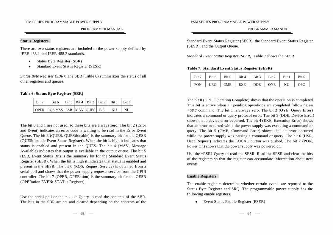
Status Byte Register (SBR): The SBR (Table 6) summarizes the status of all other registers and queues.
Table 6: Status Byte Register (SBR)
Bit 7 Bit 6 Bit 5 Bit 4 Bit 3 Bit 2 Bit 1 Bit 0
OPER RQS/MSS ESB MAV QUES E/E NU NU
The bit 0 and 1 are not used, so these bits are always zero. The bit 2 (Error and Event) indicates an error code is waiting to be read in the Error Event Queue. The bit 3 (QUES, QUEStionable) is the summary bit for the QESR (QUEStionable Event Status Register). When the bit is high it indicates that status is enabled and present in the QUES. The bit 4 (MAV, Message Available) indicates that output is available in the output queue. The bit 5 (ESB, Event Status Bit) is the summary bit for the Standard Event Status Register (SESR). When the bit is high it indicates that status is enabled and present in the SESR. The bit 6 (RQS, Request Service) is obtained from a serial poll and shows that the power supply requests service from the GPIB controller. The bit 7 (OPER, OPERation) is the summary bit for the OESR (OPERation EVENt STATus Register).
Use the serial poll or the *STB? Query to read the contents of the SBR. The bits in the SBR are set and cleared depending on the contents of the
PSM SERIES PROGRAMMABLE POWER SUPPLY
PROGRAMMER MANUAL
⎯ 64 ⎯
Standard Event Status Register (SESR), the Standard Event Status Register (SESR), and the Output Queue.
Standard Event Status Register (SESR): Table 7 shows the SESR
Table 7: Standard Event Status Register (SESR)
Bit 7 Bit 6 Bit 5 Bit 4 Bit 3 Bit 2 Bit 1 Bit 0
PON URQ CME EXE DDE QYE NU OPC
The bit 0 (OPC, Operation Complete) shows that the operation is completed. This bit is active when all pending operations are completed following an *OPC command. The bit 1 is always zero. The bit 2 (QYE, Query Error) indicates a command or query protocol error. The bit 3 (DDE, Device Error) shows that a device error occurred. The bit 4 (EXE, Execution Error) shows that an error occurred while the power supply was executing a command or query. The bit 5 (CME, Command Error) shows that an error occurred while the power supply was parsing a command or query. The bit 6 (USR, User Request) indicates the LOCAL button was pushed. The bit 7 (PON, Power On) shows that the power supply was powered on.
Use the *ESR? Query to read the SESR. Read the SESR and clear the bits of the registers so that the register can accumulate information about new events.
Enable Registers
The enable registers determine whether certain events are reported to the Status Byte Register and SRQ. The programmable power supply has the following enable registers.
Event Status Enable Register (ESER)
PSM SERIES PROGRAMMABLE POWER SUPPLY
PROGRAMMER MANUAL
⎯ 65 ⎯
OPERation Enable Register QUEStionable Enable Register Service Request Enable Register (SRER)
When one of the bits of the enable registers is high and the corresponding bit in the status register is high, the enable registers will perform a logical OR function, the output that controls the set bit of the Status Byte Register is high.
Various commands set the bits in the enable registers. The following sections describe the enable registers and the commands that set them.
Event Status Enable Register (ESER): The ESER controls which types of events are summarized by the Event Status Bit (ESB) in the SBR. The bits of the ESER correspond to the bits of the SESR.
Use the *ESE command to set the bits in ESER. Use the *ESE? query to read it.
OPERation Enable Register: Even though the OPERation Enable Register is present in the programmable power supplies, the OPERation registers do not report any conditions.
QUEStionable Enable Register: The QUEStionable Enable Register controls which types of events are summarized by the QUES status bit in the SBR. Use the STATus:QUEStionable:ENABle command to set the bits in the QUEStionable Enable register. Use the STATus:QUEStionable:ENABle? query to read it.
Service Request Enable Register (SRER): The SRER controls which bits in the SBR generate a service request.
Use the *SRE command to set the SRER. Use the *SRE? query to read it.
PSM SERIES PROGRAMMABLE POWER SUPPLY
PROGRAMMER MANUAL
⎯ 66 ⎯
Queues
The output queue is included to power supplies.
Output Queue: The programmable power supplies store query responses in the output queue by succeeding the IEEE 488.2 protocol. If the power supply receives a new command or query message after a message terminator, the power supply will clear and reset this queue each time. The computer must read a query response before it sends the next command (or query) or it loses response to earlier queries.
Error/Event Queues When an error or event occurs, the output queue stores the message. The output queue stores and reports the messages on a FIFO (first in first out) state. The SYSTem:ERRor? query reads the next item from the output queue. If output queue overflows, the error message is –350, “Queue overflow”; the queue can’t store or report succeeding messages till it is read or cleared.
Error Message5 -101 Invalid character
-102 Syntax error
-103 Invalid separator
-104 Data type error
-105 GET not allowed
-108 Parameter not allowed
-109 Missing parameter
-112 Program mnemonic too long
-113 Undefined header
-121 Invalid character in number
PSM SERIES PROGRAMMABLE POWER SUPPLY
PROGRAMMER MANUAL
⎯ 67 ⎯
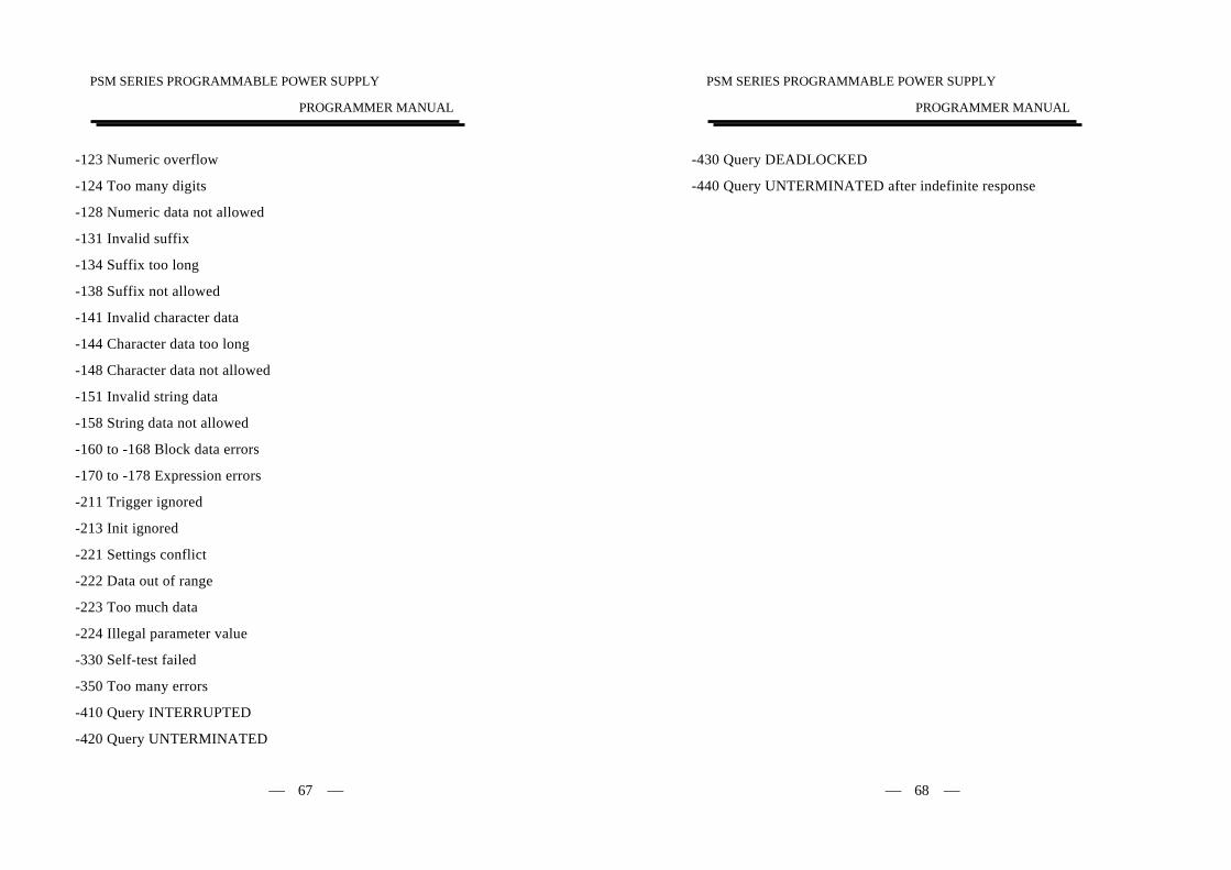
-123 Numeric overflow
-124 Too many digits
-128 Numeric data not allowed
-131 Invalid suffix
-134 Suffix too long
-138 Suffix not allowed
-141 Invalid character data
-144 Character data too long
-148 Character data not allowed
-151 Invalid string data
-158 String data not allowed
-160 to -168 Block data errors
-170 to -178 Expression errors
-211 Trigger ignored
-213 Init ignored
-221 Settings conflict
-222 Data out of range
-223 Too much data
-224 Illegal parameter value
-330 Self-test failed
-350 Too many errors
-410 Query INTERRUPTED
-420 Query UNTERMINATED
PSM SERIES PROGRAMMABLE POWER SUPPLY
PROGRAMMER MANUAL
⎯ 68 ⎯
-430 Query DEADLOCKED
-440 Query UNTERMINATED after indefinite response