Modbus Installation and operating instructions FA 5xx … · FA 5xx Modbus RTU Installation V1.01...
14
FA 5xx Modbus RTU Installation V1.00 Side 1 of 14 EN - English Modbus Installation and operating instructions FA 5xx Sensors
Transcript of Modbus Installation and operating instructions FA 5xx … · FA 5xx Modbus RTU Installation V1.01...

FA 5xx Modbus RTU Installation V1.00 Side 1 of 14
EN - English
Modbus Installation and operating instructions
FA 5xx Sensors

FA 5xx Modbus RTU Installation V1.00 Side 1 of 14
I. Foreword
Dear customer,
thank you very much for deciding in favour of the FA 5xx. Please read this installation and operation manual carefully before mounting and initiating the device and follow our advice. A riskless operation and a correct functioning of the dew point sensors are only guaranteed in case of careful observation of the described instructions and notes.
Sales Office South/Geschäftsstelle Süd
Zindelsteiner Str. 15 D-78052 VS-Tannheim
Tel.: +49 (0) 7705 978 99 0 Fax: +49 (0) 7705 978 99 20
Mail: [email protected] Web: http://www.cs-instruments.com
Sales Office North/Geschäftsstelle Nord
Am Oxer 28c D-24955 Harrislee
Tel.: +49 (0) 461 700 20 25 Fax: +49 (0) 461 700 20 26
Mail: [email protected] Web: http://www.cs-instruments.com

FA 5xx Modbus RTU Installation V1.00 Side 2 of 14
II. Table of contents
I. Foreword ....................................................................................................................... 1
II. Table of contents ....................................................................................................... 2
1 Instructions ................................................................................................................... 3
1.1 Definition and abbreviation .................................................................................................... 3
1.2 References ............................................................................................................................... 3
2 Technical data FA 5xx .................................................................................................. 4
2.1 FA 5xx MODBUS RTU specification ...................................................................................... 4
2.2 General Modbus Information ................................................................................................. 4 2.2.1 Serial transmission modes (RTU) ...................................................................................... 4
3 Installation ..................................................................................................................... 5
3.1 RS 485 bus wiring ( Modbus RTU) ........................................................................................ 5 3.1.1 Termination ........................................................................................................................ 5 3.1.2 Bias .................................................................................................................................... 5 In order to avoid undefined bus levels, at any llocation on the bus, a bias network, one resistor to VCC (Modbus A) as well as to GND (Modbus B), has to be used. .................................................. 5
4 Modbus RTU communication settings ........................................................................ 6
4.1 Accessing and changing Modbus settings .......................................................................... 6
5 Modbus TCP communication settings ........................................................................ 6
6 Modbus addressing model ........................................................................................... 6
6.1 Function Code 3 (Read holding register) ............................................................................. 7
6.2 Function code 16 (Write multiple registers) ......................................................................... 7
7 Modbus Holding Register ............................................................................................. 8
7.1 Basic Values Register (1…1000) .......................................................................................... 8
7.2 Values register (1001….1200) .............................................................................................. 9
7.3 Device settings register ....................................................................................................... 10 7.3.1 Modbus Settings (2001…2006) ...................................................................................... 10 7.3.2 Analog Scaling Settings (2007…2011) .......................................................................... 10 7.3.3 System Pressure Settings (2013…2035) ...................................................................... 11 7.3.4 One point calibration (2019…2034) ............................................................................... 11
7.4 Free / User space register (2501… 2520) .......................................................................... 12
7.5 Data format test register (64001… 64003) ........................................................................ 12
8 Appendix ......................................................................................................................13
8.1 APPENDIX A - Exception codes .......................................................................................... 13

FA 5xx Modbus RTU Installation V1.00 Side 3 of 14
1 Instructions
This manual is intended to provide instructions for the installation and use of the FA 5xx
MODBUS function. The FA 5xx MODBUS function can let the MODBUS master device to
read out the online measurement values.
This manual is not intended to be a complete tutorial on the MODBUS RTU protocol, and it
is assumed the end user already has a general working knowledge of MODBUS RTU
Communications, especially in respect of master station configuration and operation.
However an overview is included in the following section to explain some of the
fundamental aspects of the protocol.
1.1 Definition and abbreviation
CRC
Cyclic Redundancy Check
Used for error—checking in MODBUS RTU. See appendix
Modbus Master A MODBUS device, which is able to access data in one or more connected MODBUS slaves
Modbus Slave A MODBUS device, which is able to respond to requests from a
single MODBUS master
Modbus Address Throughout this document the following notation is used to address MODBUS RTU registers see chapter 8 Addressing: Holding Register 1009 is addressed in messages by 1008
PDU MODBUS protocol data unit
ADU MODBUS application data unit
MBAP MODBUS application protocol
RS485 Refers to the 2—wire communication standard defined by EIA/TIA-485. (Physical layer)
Ethernet
1.2 References
1. MODBUS over Serial Line Specification and Implementation Guide V1.02 modbus.org 2006 Dec 20
2. MODBUS APPLICATION PROTOCOL SPECIFICATION V1.1b modbus.org 2006 Dec 28
3. MODBUS Messaging on TCP/IP implementation Guide V1.0b 2006 Oct 34
4. FA 5xx operation manuals

FA 5xx Modbus RTU Installation V1.01 Side 4 of 14
2 Technical data FA 5xx
2.1 FA 5xx MODBUS RTU specification
Device type Slave
Baud Rates 1200,2400, 4800, 9600, 19200, 38400 bps
Device address range 1...247
Electrical Interface RS485, 2 wire
Protocol RTU
Supported function code 3 read holding register
16 write multiple register
Broadcast No
Standard Modbus over serial line V1.02
2.2 General Modbus Information
The DS 500 Modbus module complies with the Modbus serial line protocol [Reference 1].
Among other things this implies a master-slave protocol at level 2 of the OSI model. One
node (the master) issues explicit commands to one of the ,,sIave"-nodes and processes
responses. Slave nodes will not transmit data without a request from the master node, and
do not communicate with other slaves.
Modbus is a mono master system, which means that only one master can be connected
at the time.
2.2.1 Serial transmission modes (RTU)
The FA 5xx Modbus mode support only one serial transmission modes; the RTU
mode. The transmission mode defines the bit contents of message fields
transmitted serially on the line. It determines how information is packed into the message
fields and decoded.
The transmission mode and serial port parameters must be the same for all devices on a
Modbus serial line.
RTU mode Modbus Application Data Unit (ADU) frame is shown below, and is valid for
both requests and responses.
Slave address Function code Data CRC
1 byte 1byte 0 up to 252 byte(s) 2 bytes
Table 1
Further details of the Modbus protocol can be found in Reference 1 and 2.

FA 5xx Modbus RTU Installation V1.01 Side 5 of 14
3 Installation
3.1 RS 485 bus wiring ( Modbus RTU)
Slave 1 Slave n
A
B
Common
T TR R
Master
TR
FA 5xx
Pin 2Pin 4
Pin 3
68
0R
68
0R
12
0R
Terminierung / Bias
3.1.1 Termination
Note: In case the FA 5xx dew point sensor is the last device in the RS485 network then a termination with 120R between (between Pin 2 and Pin 4) is necessary.
Bus cable:
Only cables according to the recommendations of EIA 485 standard should be used. A
maximum of 64 devices may be connected to one segment. The bus cable must be laid at
a distance of at least 20 cm from other cables. It should be laid in a separate, conductive,
and earthed cable trunking. It must be ensured that no potential differences occur between
the individual devices on the bus.
3.1.2 Bias
In order to avoid undefined bus levels, at any llocation on the bus, a bias network, one resistor to VCC (Modbus A) as well as to GND (Modbus B), has to be used.
Cable specification:
Impedance: 135 -165 Ohm @ 3 to 20 Mhz
Cable capacity: < 30pF/m
Cable diameter: > 0.64 mm
Cross section: > 0.34 mm2, conforms to AWG 22
Loop resistance < 110 Ohm per km
Screening: Cu shielding braid or shielding braid and shielding foil

FA 5xx Modbus RTU Installation V1.01 Side 6 of 14
4 Modbus RTU communication settings
Before communication with the master, baudrate, address, and framing must be defined
4.1 Accessing and changing Modbus settings
The Modbus communication settings could be changed by using either the PC service software from CS Instruments, the data loggers DS 400, DS 500 or the handheld device PI 500 Note:
It is recommended NOT to use the default address in a multi-slave network. It is of great
importance to ensure at the time of the procedure of device addressing, that there
is not two devices with the same address. In such a case, an abnormal behaviour of the
whole serial bus can occur, the master being then in the impossibility to communicate with
all present slaves on the bus.
5 Modbus TCP communication settings
Device type Slave
Baud Rates 1200,2400, 4800, 9600, 19200, 38400 bps
Device address range 1...247
Electrical Interface RS485, 2 wire
Protocol RTU
Supported function code 3 read holding register
16 write multiple register
Broadcast No
Standard Modbus over serial line V1.02
6 Modbus addressing model
The FA 5xx RS485 Modbus allows read/write access according chapter 8
Not defined registers are not accessible / not supported.
Byte Order:
The size of each Modbus-register is 2 Byte. For a 32 bit value two Modbusregister will be read out by the FA 5xx. Accordingly for a 16bit Value only one register is read.
Data format FA 5xx:
Single Word Double Word
For verification of a correct data format please read out register 64000 or 64004.Result should be:
Register 64000: Long Integer Value =1 000 000
Register 64004: Float Value = 1 000 000.0
HByte LByte 18 => 00 12 Data Order 1. Byte 2. Byte 00 12
HWord LWord HByte LByte HByte LByte 29235175522 => AE 41 56 52 Data Order 1.Byte 2.Byte 3.byte 4.Byte AE 41 56 52

FA 5xx Modbus RTU Installation V1.01 Side 7 of 14
6.1 Function Code 3 (Read holding register)
General exceptions:
• Requesting less than 1 or more than 125 registers => Exception 3 (Illegal data value)
• Requesting more than max. message size (27 registers) => Exception 2(Illegal data address)
• Requesting data out of defined range of registers chapter 8 => Exception 2 (Illegal data address)
Application exceptions:
• Application errors => Exception 4 (Slave device error)
Holes/register alignment:
• The read command always returns data if no exception is given. Bad
Start/end alignment will result in only parts of the data item being read.
6.2 Function code 16 (Write multiple registers)
In general only status register (register 2001 – 2064) are writable.
General exceptions: • Writing less than 1 or more than 63 registers => Exception 3 (Illegal data value) • If ByteCount is not exactly 2 times NoOfRegisters => Exception 3 (Illegal data value) • Exceeding max. message size (27 registers) => Exception 2 (Illegal data address) • Writing data out of defined register range chapter 8 =>Exception 2 (Illegal data address) Application exceptions: • Application errors => Exception 4 (Slave device error) • Application errors include writing to ReadOnIy holding registers Holes / register alignment: • If start-address is not the start of a mapped holding register => Exception 2 (Illegal data address) • Writing to holes is allowed (ie ignored - and no exception occurs) — except for the condition described above

FA 5xx Modbus RTU Installation V1.01 Side 8 of 14
7 Modbus Holding Register
7.1 Basic Values Register (1…1000)
Modbus Register
Modbus Address
No.of Byte
Data Type
Description Default Setting
Read Write
Unit /Comment
1 0 4 Unit 32 Serial Number
0 R sprintf(str,"%u.%02u",sw>>16,sw&0xffff)
3 2 4 Unit 32 SoftwareVersion
0 R sprintf(str,"%u.%02u",hw>>16,hw&0xffff)
5 4 4 Unit 32 Hardware version 0 R
7 6 4 Unit 32 Production Code 0 R
9 8 4 Unit 32 Production date 0 R Unix Time
11 10 4 Unit 32 Calibration date 0 R Unix Time
13 12 4 Unit 32 Part Number 0 R
15 14 4 Unit 32 Run Time Counter 0 R [sec]
17 16 4 Unit 32 Code signature 0 R
19 18 4 Unit 32 Atex Number 0 R

FA 5xx Modbus RTU Installation V1.01 Side 9 of 14
7.2 Values register (1001….1200)
Modbus Register
Modbus Address
No.of Byte
Data Type
Description Default Setting
Read Write
Unit /Comment
1001 1000 4 Float Temperature
R [°C]
1003 1002 4 Float Temperature
R [°F]
1005 1004 4 Float Relative Humidity R [%]
1007 1006 4 Float Dew Point R [°Ctd]
1009 1008 4 Float Dew Point R [°Ftd]
1011 1010 4 Float Absolute Humidity R [g/m³]
1013 1012 4 Float Absolute Humidity R [mg/m³]
1015 1014 4 Float Humidity Grade R [g/kg]
1017 1016 4 Float Vapor Ratio (Volume) R [ppm]
1019 1018 4 Float Saturation vapor pressure R [hPa]
1021 1020 4 Float Partial Vapor Pressure R [hPa]
1023 1022 4 Float Atmospheric DewPoint R [°Ctd]
1025 1024 4 Float Atmospheric DewPoint R [°Ftd]

FA 5xx Modbus RTU Installation V1.01 Side 10 of 14
7.3 Device settings register
7.3.1 Modbus Settings (2001…2006)
Modbus Register
Modbus Address
No.of Byte
Data Type Description Default Setting
Read Write
Unit /Comment
2001 2000 2 UInt16 Modbus ID 1 R/W Modbus ID 1…247
2002 2001 2 UInt16 Baudrate 4 R/W 0 = 1200 1 = 2400 2 = 4800 3 = 9600 4 = 19200 5 = 38400
2003 2002 2 UInt16 Parity 1 R/W 0 = none 1 = even 2 = odd
2004 2003 2 UInt16 Number of Stopbits R/W 0 = 1 Stop Bit 1 = 2 Stop Bit
2005 2004 2 UInt16 Word Order 0xABCD R/W 0xABCD = Big Endian 0xCDAB = Middle Endian
2006 2005 2 UInt16 Modbus Enabled FA510: 1 FA515: 0
R/W 0 = Modbus disabled 1 = Modbus Enabled
7.3.2 Analog Scaling Settings (2007…2011)
Modbus Register
Modbus Address
No.of Byte
Data Type Description Default Setting
Read Write
Unit /Comment
2007 2006 4 UInt32 Output Value 4 R/W 0 = 4-20mA disabled 1 = Temperature [°C] 2 = Temperature [°F] 3 = relative Humidity [%] 4 = DewPoint [°C] 5 = DewPoint [°F] 6 = Absolute Humidity [g/m3] 7 = Absolute Humidity [mg/m3] 8 = Humidity Grade [g/kg] 9 = Vapor Ratio [ppm] 10 = Saturation Vapor Pressur [hPa] 11 = Partial Vapor Pressure [hPa] 12 = Atmospheric DewPoint [°C] 13 = Atmospheric DewPoint [°F]
2009 2008 4 float 4mA Scale Low -80 R/W
2011 2010 4 float 20mA Scale High 20 R/W
FA 5xx Modbus RTU Installation V1.01 Side 11 of 14
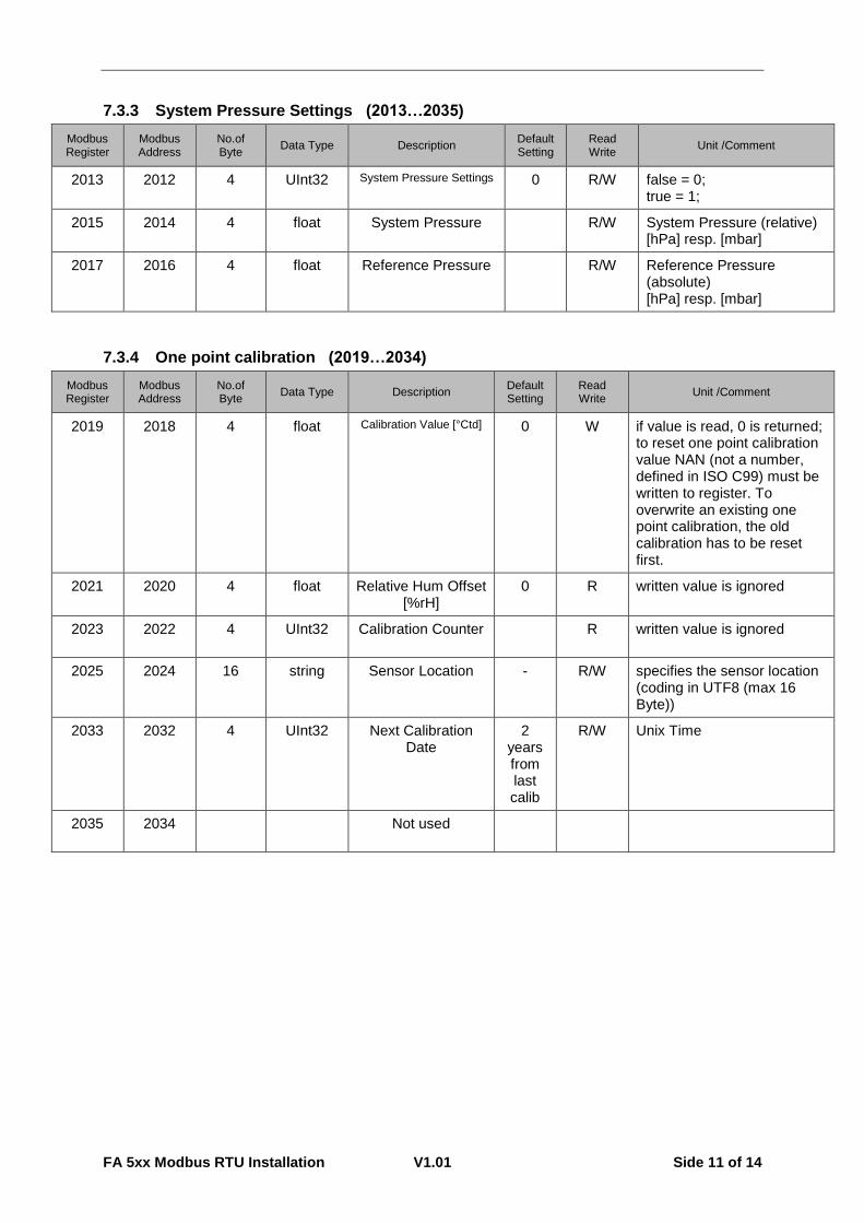
7.3.3 System Pressure Settings (2013…2035)
Modbus Register
Modbus Address
No.of Byte
Data Type Description Default Setting
Read Write
Unit /Comment
2013 2012 4 UInt32 System Pressure Settings 0 R/W false = 0; true = 1;
2015 2014 4 float System Pressure R/W System Pressure (relative) [hPa] resp. [mbar]
2017 2016 4 float Reference Pressure R/W Reference Pressure (absolute) [hPa] resp. [mbar]
7.3.4 One point calibration (2019…2034)
Modbus Register
Modbus Address
No.of Byte
Data Type Description Default Setting
Read Write
Unit /Comment
2019 2018 4 float Calibration Value [°Ctd] 0 W if value is read, 0 is returned; to reset one point calibration value NAN (not a number, defined in ISO C99) must be written to register. To overwrite an existing one point calibration, the old calibration has to be reset first.
2021 2020 4 float Relative Hum Offset [%rH]
0 R written value is ignored
2023 2022 4 UInt32 Calibration Counter R written value is ignored
2025 2024 16 string Sensor Location - R/W specifies the sensor location (coding in UTF8 (max 16 Byte))
2033 2032 4 UInt32 Next Calibration Date
2 years from last calib
R/W Unix Time
2035 2034 Not used

FA 5xx Modbus RTU Installation V1.01 Side 12 of 14
7.4 Free / User space register (2501… 2520)
Diese Register sind frei belegbare Register.
Modbus Register
Modbus Address
No.of Byte
Data Type Description Default Setting
Read Write
Unit /Comment
2501 2500 2 user defined user defined content 0xff R/W
2502 2501 2 user defined user defined content 0xff R/W
2503 2502 2 user defined user defined content 0xff R/W
2504 2503 2 user defined user defined content 0xff R/W
2505 2504 2 user defined user defined content 0xff R/W
2506 2505 2 user defined user defined content 0xff R/W
2507 2506 2 user defined user defined content 0xff R/W
2508 2507 2 user defined user defined content 0xff R/W
2509 2508 2 user defined user defined content 0xff R/W
2510 2509 2 user defined user defined content 0xff R/W
2511 2510 2 user defined user defined content 0xff R/W
2512 2511 2 user defined user defined content 0xff R/W
2513 2512 2 user defined user defined content 0xff R/W
2514 2513 2 user defined user defined content 0xff R/W
2515 2514 2 user defined user defined content 0xff R/W
2516 2515 2 user defined user defined content 0xff R/W
2517 2516 2 user defined user defined content 0xff R/W
2518 2517 2 user defined user defined content 0xff R/W
2519 2518 2 user defined user defined content 0xff R/W
2520 2519 2 user defined user defined content 0xff R/W
7.5 Data format test register (64001… 64003)
Modbus Register
Modbus Address
No.of Byte
Data Type Description Default Setting
Read Write
Unit /Comment
64001 64000 4 Dword 1000000 x R format test for Dword
64003 64002 4 float 1000000.0 x R format test for float

FA 5xx Modbus RTU Installation V1.01 Side 13 of 14
8 Appendix
8.1 APPENDIX A - Exception codes
The DS500 Modbus uses the following exception codes when responding to the master
Exception Code Exception name
0x01 Illegal function
0x02 Illegal data address
0x03 Illegal data value
0x04 Slave device failure
0x05 Acknowledge
0x06 Slave device busy
Stand: 2016/06/16, version 1.01