Modal Analysis of Post-Wall Waveguides and Waveguide ... · posts are introduced into the...
25
________________________________________________________________________________________ 1 General and Theoretical Electrical Engineering (ATE), Faculty of Engineering, University of Duisburg-Essen, and CENIDE – Center for Nanointegration Duisburg-Essen, D-47048 Duisburg, Germany, e-mail: [email protected], daniel.erni@uni- duisburg-essen.de 2 Faculty of Information Science and Electrical Engineering, Kyushu University, Fukuoka 819-0395, Japan, e-mail: [email protected] Modal Analysis of Post-Wall Waveguides and Waveguide- based Filters for Micro and Millimeter Waves V. Jandieri 1 K. Yasumoto 2 D. Erni 1 Abstract − A semi-analytical method to analyze post-wall waveguides and circuits based on a model for two- dimensional photonic crystals formed by layered periodic arrays of circular cylinders is presented. The propagation constant of the fundamental TE mode, the attenuation constant due to transversal leakage loss and the effective width of an equivalent rectangular waveguide are calculated. When additional metallic posts are introduced into the rectangular waveguide, compact functional post-wall waveguide-based passive circuits are formed, which may be applicable to mm-wave and THz operation frequencies. The S-parameters of post- wall circuits such as e.g. bandpass filters are calculated using the image theory combined with the lattice sums technique. 1 INTRODUCTION The post-wall waveguide or substrate integrated waveguide (SIW), has received growing attention because of their promising applications in planar circuit components operating in the microwave and millimeter wave frequency range [1]. The post-wall waveguide is formed by periodically distributed (usually metallic) posts or posts with a high dielectric permittivity. It allows the “planarization” of non-planar structures such as conventional rectangular waveguides and they can completely be integrated together with planar structures onto the same substrate with the same processing or fabrication techniques. Functional post-wall circuits are designed by inserting additional metallic or dielectric posts into the post-wall waveguide. The modal properties and the performance of post-wall waveguides, devices and circuits have been extensively investigated [also in the framework of SIWs] using various analytical or numerical techniques [2, 3]. The electromagnetic field of the post-wall waveguide is confined in the lateral direction by periodic arrays of metallic posts placed on both sides of the waveguide channel. The vertical extent of the waveguide bounded by two metallic plates is much smaller than the wavelength, hence the electromagnetic field is uniform in the vertical direction, which applies for 0 m TE -like modes. This kind of periodic waveguide may be represented by a two-dimensional (2D) photonic crystal (PhC) defect waveguide formed by the corresponding arrangement of parallel, infinitely long extended circular cylinders (where no field variation along vertical direction is present). In the manuscript, we report on a novel semi-analytical approach for analyzing such post-wall waveguides and circuits based on the model of two-dimensional PhCs. The generalized reflection matrix is used to derive the dispersion equation for 0 m TE modes. Solving this dispersion equation based on a perturbation analysis, the attenuation constant (due to the leakage loss) and the effective width of the equivalent rectangular waveguide are calculated. To validate the proposed formalism, numerical examples for post-wall waveguides and post-wall waveguide-based passive circuit, such as bandpass filter, are presented and compared to those reported in [2, 3] yielding a perfect agreement between the S-parameters over a wide frequency range. The interested reader may refer to our recently published papers [4, 5], where the detailed derivations of equations and calculation process are given. 2 FORMULATION OF THE PROBLEM The post-wall waveguide is confined by two N periodic arrays of conducting circular posts (each forming a planar lattice) embedded in a dielectric substrate that is vertically bounded by two parallel conducting plates. Figure 1 depicts the post-wall waveguide structure formed by the N-layered square lattice. The electromagnetic fields are uniform in the y-direction ( 0 y ∂∂ = ) and the dominant mode 10 TE is excited. As mentioned above this post-wall waveguide is modeled by a two-dimensional PhC waveguide formed by parallel circular rods infinitely extended in the y direction. Let us consider TE modes consisting of ( , , ) y x z E H H field components. If we assume a longitudinal field variation of e i z β , the guided wave propagating within the waveguide channel /2 ≤ a x is expressed as follows [4]: + (,) (,) (,) + − − = ⋅ + ⋅ U U y xz xz xz E c c (1) with [ ] { } (, ) exp ( / 2) exp( ) m xz i x a i z κ β δ ± = U (2) [ ] ( 0, 1, 2, ) c ± ± = = ± ± c (3) where 2 / , β β π = + h 2 0 2 , κ ωε μ β = − s s ε is the permittivity of the dielectric substrate, β stands for the propagation constant, and ± c are the column vectors whose elements c + and c − represent the amplitudes of the transversally up-going and down- 403
Transcript of Modal Analysis of Post-Wall Waveguides and Waveguide ... · posts are introduced into the...
________________________________________________________________________________________
1 General and Theoretical Electrical Engineering (ATE), Faculty of Engineering, University of Duisburg-Essen, and CENIDE – Center for Nanointegration Duisburg-Essen, D-47048 Duisburg, Germany, e-mail: [email protected], [email protected] 2 Faculty of Information Science and Electrical Engineering, Kyushu University, Fukuoka 819-0395, Japan, e-mail: [email protected]
Modal Analysis of Post-Wall Waveguides and Waveguide-based Filters for Micro and Millimeter Waves
V. Jandieri1 K. Yasumoto2 D. Erni1
Abstract − A semi-analytical method to analyze post-wall waveguides and circuits based on a model for two-dimensional photonic crystals formed by layered periodic arrays of circular cylinders is presented. The propagation constant of the fundamental TE mode, the attenuation constant due to transversal leakage loss and the effective width of an equivalent rectangular waveguide are calculated. When additional metallic posts are introduced into the rectangular waveguide, compact functional post-wall waveguide-based passive circuits are formed, which may be applicable to mm-wave and THz operation frequencies. The S-parameters of post-wall circuits such as e.g. bandpass filters are calculated using the image theory combined with the lattice sums technique.
1 INTRODUCTION
The post-wall waveguide or substrate integrated waveguide (SIW), has received growing attention because of their promising applications in planar circuit components operating in the microwave and millimeter wave frequency range [1]. The post-wall waveguide is formed by periodically distributed (usually metallic) posts or posts with a high dielectric permittivity. It allows the “planarization” of non-planar structures such as conventional rectangular waveguides and they can completely be integrated together with planar structures onto the same substrate with the same processing or fabrication techniques. Functional post-wall circuits are designed by inserting additional metallic or dielectric posts into the post-wall waveguide. The modal properties and the performance of post-wall waveguides, devices and circuits have been extensively investigated [also in the framework of SIWs] using various analytical or numerical techniques [2, 3]. The electromagnetic field of the post-wall waveguide is confined in the lateral direction by periodic arrays of metallic posts placed on both sides of the waveguide channel. The vertical extent of the waveguide bounded by two metallic plates is much smaller than the wavelength, hence the electromagnetic field is uniform in the vertical direction, which applies for 0mTE -like modes. This kind of periodic waveguide may be represented by a two-dimensional (2D) photonic crystal (PhC) defect waveguide formed by the corresponding arrangement of parallel, infinitely long extended circular cylinders (where no field variation along vertical direction is present). In the manuscript, we report on a novel semi-analytical approach for analyzing such post-wall waveguides and circuits based on the model of two-dimensional PhCs. The
generalized reflection matrix is used to derive the dispersion equation for 0mTE modes. Solving this dispersion equation based on a perturbation analysis, the attenuation constant (due to the leakage loss) and the effective width of the equivalent rectangular waveguide are calculated. To validate the proposed formalism, numerical examples for post-wall waveguides and post-wall waveguide-based passive circuit, such as bandpass filter, are presented and compared to those reported in [2, 3] yielding a perfect agreement between the S-parameters over a wide frequency range. The interested reader may refer to our recently published papers [4, 5], where the detailed derivations of equations and calculation process are given.
2 FORMULATION OF THE PROBLEM
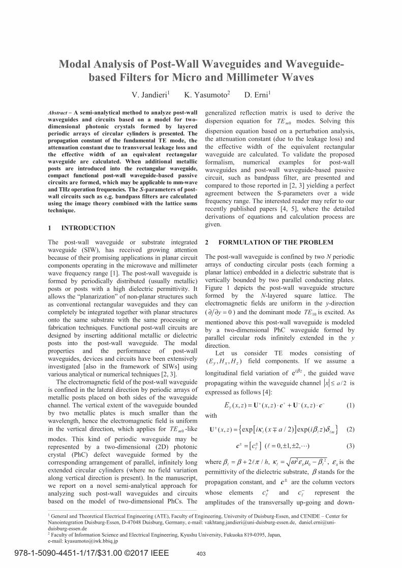
The post-wall waveguide is confined by two N periodic arrays of conducting circular posts (each forming a planar lattice) embedded in a dielectric substrate that is vertically bounded by two parallel conducting plates. Figure 1 depicts the post-wall waveguide structure formed by the N-layered square lattice. The electromagnetic fields are uniform in the y-direction ( 0y∂ ∂ = ) and the dominant mode 10TE is excited. As mentioned above this post-wall waveguide is modeled by a two-dimensional PhC waveguide formed by parallel circular rods infinitely extended in the y direction. Let us consider TE modes consisting of ( , , )y x zE H H field components. If we assume a
longitudinal field variation of ei zβ , the guided wave propagating within the waveguide channel / 2≤ ax is expressed as follows [4]:
+( , ) ( , ) ( , )+ − −= ⋅ + ⋅U Uy x z x z x zE c c (1) with
[ ]{ }( , ) exp ( / 2) exp( ) mx z i x a i zκ β δ± =U (2)
[ ] ( 0, 1, 2, )c± ±= = ± ±c (3)
where 2 / ,β β π= + h 20
2 ,κ ω ε μ β= −s sε is the permittivity of the dielectric substrate, β stands for the propagation constant, and ±c are the column vectors whose elements c+ and c− represent the amplitudes of the transversally up-going and down-
403
going -th Floquet mode. The amplitude vectors ±csatisfy the following relations:
, ,( ) ( )Nω β ω β± ⋅= W Rc c (4) with
[ ],( ) exp( )ω β κ δ=W mi a (5)
where ,( )N ω βR denotes the generalized reflection matrix of the confining N-layered periodic arrays of circular rods, whose ( , )m element connects the reflected -th Floquet mode to the incident m -th Floquet mode. The generalized reflection matrix
( , )N ω βR can be calculated using the T-matrix of a single circular rod together with the lattice sums as defined in [4]. From (4) we get the transcendental dispersion equation to determine the mode propagation constant β as follows:
det[ ( , ) ( , )] 0Nω β ω β =I W R (6) where the signs stand for even (–) and odd (+) modes, respectively. If only the fundamental Floquet mode with 0= is propagating and all other diffraction orders are evanescent in the y direction, (6) is reduced to the following expression:
0 001 ( ) ( , ) 0exp ω βκ =NRi a (7)
Where 00 ( , )NR β ω denotes the (0,0) element of
( , )N ω βR . As will be shown later, the reduced dispersion equation (7) gives an excellent approximation to the full matrix equation (6). It is well-known [2] that when the transversal leakage of electromagnetic field through the gaps between the posts is sufficiently small, the post-wall waveguide modes practically coincide with the 0mTE modes of an equivalent rectangular waveguide with an effective width ea a a= + Δ . Let us now calculate the effective width ea using the reduced dispersion equation (7) for the even mode. If the leakage is small enough, the imaginary part of β can be regarded as a weak perturbation. Such a treatment applies when
00 ( , )NR ω β satisfies the following condition:
00 ( , ) 1NR β ω ≈ . (8)
In this case, (7) yields real-valued ( )β ω and 0 ( )κ ω as unperturbed solutions. For the specified values of
( )β ω and 0 ( )κ ω , the width a of the original post-wall waveguide is changed to ea a a= +Δ . Using boundary condition for the perfect electrical conductor (PEC) we have:
0/ ( ).ea π κ ω= (9) Although ea slightly changes with ω variations, it may be practically regarded as almost constant within the same order of approximation as assumed in (8).
Fig. 1. Schematic of a post-wall waveguide bounded by two adjacent N-layered post-wall arrays.
3 LEAKAGE LOSS AND ATTENUATION CONSTANT
In this Section we briefly present the perturbation analysis taking into account the principle of power conservation to calculate the attenuation constant due to leakage loss in the post-wall waveguide. Due to transversal leakage the guided waves carrying a total
power/2 *
0Re{ }
a
y xzP E H dx−= will attenuate as a
function of z (‘*’ denotes the complex conjugate). In agreement with the Beer-Lambert law the carrier power zP decays exponentially with the attenuation constant α according to 2 ze α− . By the power conservation principle, the decrease of zP along z should be equal to the transversal power dissipation
per unit length xS< > *
0
1 Re{ }2
h
y zE H dzh
= . As a
result, while taking into account the orthogonality of the Floquet modes, the attenuation constant α can be expressed in the following form [4]:
2
0 00 0 00
1
2
0
( 0)
0.5 [sin( ) ]
e [sinh( ) ]γ
βα κ κ κκ
β γ γγ
−
−
=−≠
< >= = + +
+
Nx
z
Ma N
M
SP
F a a
a a R
(10)
where ( , )N ω βF is transmission matrix of the N-
layered periodic arrays, 2 2γ β= − sk denotes the propagation constant of the evanescent modes and M stands for the truncation number of the modes. Attenuation constant can be also calculated using another approach. Taking into account the fact that
decrement of 00 ( , )NR β ω from unity caused by the
transverse leakage of the guided field is a small value,
404
the attenuation constant α due to the leakage can be calculated as follows [5]:
000 0
0ln ( , )NR
aκ
α β ωβ
=− . (11)
As will be shown later, this approximation is well justified by the fact that the difference between the real part of the propagation constants β calculated for
1N = and for N = ∞ without leakage losses is negligibly small.
4 NUMERICAL RESULTS AND DICSUSSIONS
In order to confirm the validity of the long wavelength approximation to the dispersion equation, first we have calculated the propagation constant β of the fundamental TE10 mode by using the full matrix equation (6) and the reduced equation (7), respectively, and compared both results. We assumed that the conductor loss in the post-walls and the dielectric loss in the substrate are negligible. The example encompasses a post-wall structure with
0/ 2.33ε ε =s , 2.0=h mm , 0.4r mm= and 7.2a mm= [2]. Since / 5.0h r = and / 0.278h a = ,
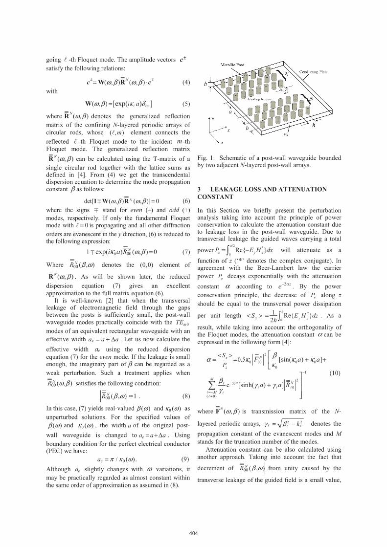
the gap width between two nearby posts is relatively small. Figure 2 displays the frequency dependence of the effective width ea of the equivalent rectangular waveguide calculated based on (9) for post-wall waveguide with 0/ 2.33ε ε =s , 2.0h mm= , 0.4r mm= ,
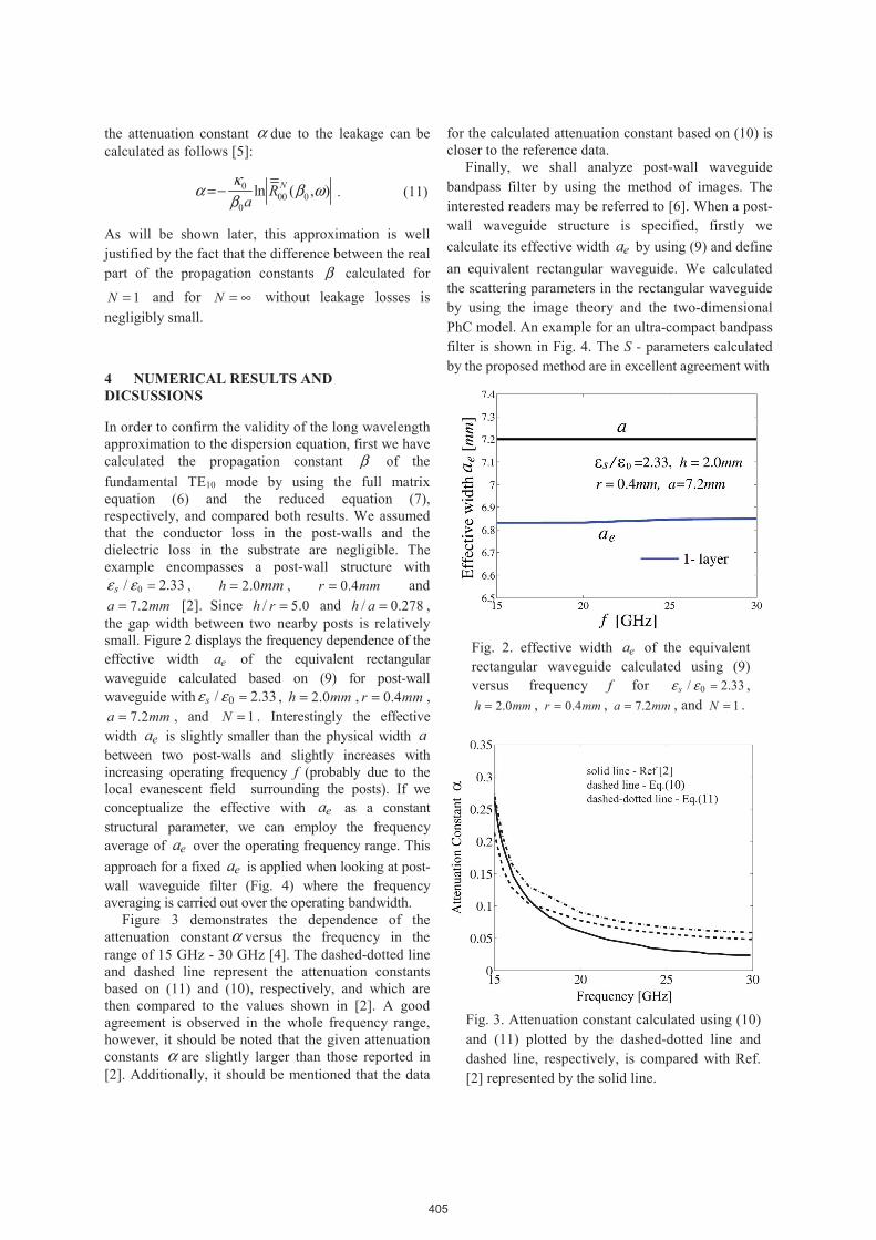
7.2a mm= , and 1N = . Interestingly the effective width ea is slightly smaller than the physical width a between two post-walls and slightly increases with increasing operating frequency f (probably due to the local evanescent field surrounding the posts). If we conceptualize the effective with ea as a constant structural parameter, we can employ the frequency average of ea over the operating frequency range. This approach for a fixed ea is applied when looking at post-wall waveguide filter (Fig. 4) where the frequency averaging is carried out over the operating bandwidth. Figure 3 demonstrates the dependence of the attenuation constantα versus the frequency in the range of 15 GHz - 30 GHz [4]. The dashed-dotted line and dashed line represent the attenuation constants based on (11) and (10), respectively, and which are then compared to the values shown in [2]. A good agreement is observed in the whole frequency range, however, it should be noted that the given attenuation constants α are slightly larger than those reported in [2]. Additionally, it should be mentioned that the data
for the calculated attenuation constant based on (10) is closer to the reference data. Finally, we shall analyze post-wall waveguide bandpass filter by using the method of images. The interested readers may be referred to [6]. When a post-wall waveguide structure is specified, firstly we calculate its effective width ea by using (9) and define an equivalent rectangular waveguide. We calculated the scattering parameters in the rectangular waveguide by using the image theory and the two-dimensional PhC model. An example for an ultra-compact bandpass filter is shown in Fig. 4. The S - parameters calculated by the proposed method are in excellent agreement with
Fig. 2. effective width ea of the equivalent rectangular waveguide calculated using (9) versus frequency f for 0/ 2.33sε ε = ,
2.0h mm= , 0.4r mm= , 7.2a mm= , and 1N = .
Fig. 3. Attenuation constant calculated using (10) and (11) plotted by the dashed-dotted line and dashed line, respectively, is compared with Ref. [2] represented by the solid line.
405
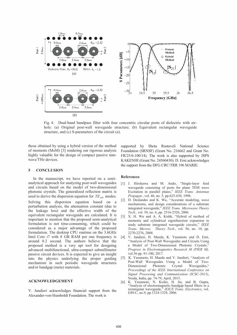
those obtained by using a hybrid version of the method of moments (MoM) [3] rendering our rigorous analysis highly valuable for the design of compact passive mm-wave/THz devices.
5 CONCLUSION
In the manuscript, we have reported on a semi-analytical approach for analyzing post-wall waveguides and circuits based on the model of two-dimensional photonic crystals. The generalized reflection matrix is used to derive the dispersion equation for 0mTE modes. Solving this dispersion equation based on a perturbation analysis, the attenuation constant (due to the leakage loss) and the effective width of the equivalent rectangular waveguide are calculated. It is important to mention that the proposed semi-analytical formulation is not time-consuming, which could be considered as a major advantage of the proposed formulation. The desktop CPU runtime on the 3.6GHz Intel Core i7 with 8 GB RAM per one frequency is around 0.2 second. The authors believe that the proposed method is a very apt tool for designing advanced multifunctional, ultra-compact submillimeter passive circuit devices. It is expected to give an insight into the physics underlying the proper guiding mechanism in such periodic waveguide structures and/or bandgap (meta) materials.
ACKNOWLEDGEMENT V. Jandieri acknowledges financial support from the Alexander-von-Humboldt Foundation. The work is
supported by Shota Rustaveli National Science Foundation (SRNSF) (Grant No. 216662 and Grant No. FR/25/6-100/14). The work is also supported by JSPS KAKENHI (Grant No. 24560430). D. Erni acknowledges the support from the DFG CRC/TRR 196 MARIE.
References [1] J. Hirokawa and M. Ando, “Single-layer feed
waveguide consisting of posts for plane TEM wave Excitation in parallel plates,” IEEE Trans. Antennas Propagat., vol. 46, no. 5, pp.625-630, 1998.
[2] D. Deslandes and K. Wu, “Accurate modeling, wave mechanisms, and design considerations of a substrate integrated waveguide,” IEEE Trans. Microwave Theory Tech., vol. 54, no. 6, pp. 2516-2526, 2006.
[3] X. H. Wu and A. A. Kishk, “Hybrid of method of moments and cylindrical eigenfunction expansion to study substrate integrated waveguide circuits,” IEEE Trans. Microw. Theory Tech., vol. 56, no. 10, pp. 2270-2276, 2008.
[4] V. Jandieri, H. Maeda, K. Yasumoto and D. Erni, “Analysis of Post-Wall Waveguides and Circuits Using a Model of Two-Dimensional Photonic Crystals,” Progress in Electromagnetics Research M (PIER M), vol.56 pp. 91-100, 2017.
[5] K. Yasumoto, H. Maeda and V. Jandieri, “Analysis of Post-Wall Waveguides Using a Model of Two-Dimensional Photonic Crystal Waveguides,“ Proceedings of the IEEE International Conference on Signal Processing and Communication (ICSC-2015), Noida, India, pp. 74-79, April, 2015.
[6] K. Yasumoto, N. Koike, H. Jia, and B. Gupta, “Analysis of electromagnetic bandgap based filters in a rectangular waveguide,” IEICE Trans. Electronics, vol. E89-C, no.9, pp.1324-1329, 2006.
Fig. 4. Dual-band bandpass filter with four concentric circular posts of dielectric with air-hole: (a) Original post-wall waveguide structure; (b) Equivalent rectangular waveguide structure, and (c) S-parameters of the circuit (a).
406
Modal Analysis of Post-Wall Waveguides and Waveguide-based Filters
for Micro and Millimeter Waves
Vakhtang Jandieri 1, Kiyotoshi Yasumoto 2 and Daniel Erni 1
1 General and Theoretical Electrical Engineering (ATE) and CENIDE – Center Nanointegration Duisburg-Essen, Duisburg, Germany
2 Department of Computer Science and Communication Engineering,Kyushu University, Fukuoka, Japan
Verona, Italy, September 11 – 15, 2017
1. Introduction
2. Model of 2D-Photonic Crystal Waveguide
3. Analysis of Post-wall Waveguides
4. Attenuation Constant and Leakage Loss
5. Numerical Examples for Post-Wall Waveguides
6. Numerical Examples for Compact Circuits
7. Conclusions
Content
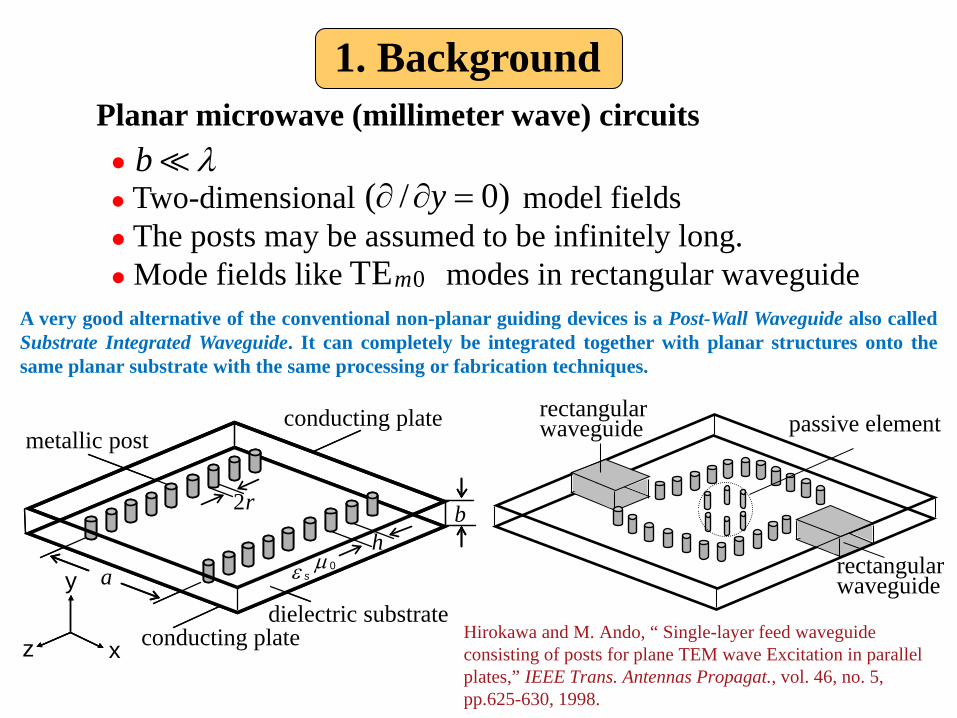
Two-dimensional model fields The posts may be assumed to be infinitely long. Mode fields like modes in rectangular waveguide
Planar microwave (millimeter wave) circuitsb λ�
( / 0)y∂ ∂ =
0TEm
passive element
rectangularwaveguide
rectangularwaveguideconducting plate
conducting platedielectric substrate
metallic post
z x
y
bh
2r
aµ 0ε s
1. Background
Hirokawa and M. Ando, “ Single-layer feed waveguide consisting of posts for plane TEM wave Excitation in parallel plates,” IEEE Trans. Antennas Propagat., vol. 46, no. 5, pp.625-630, 1998.
A very good alternative of the conventional non-planar guiding devices is a Post-Wall Waveguide also calledSubstrate Integrated Waveguide. It can completely be integrated together with planar structures onto thesame planar substrate with the same processing or fabrication techniques.
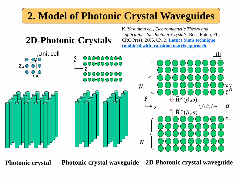
2D-Photonic Crystals
Photonic crystal
Unit cell
zx
x
z
Photonic crystal waveguide
2. Model of Photonic Crystal Waveguides
xz
hN
N
h
( , )N β ωR
( , )N β ωRa
2D Photonic crystal waveguide
K. Yasumoto ed., Electromagnetic Theory and Applications for Photonic Crystals. Boca Raton, FL: CRC Press, 2005, Ch. 3. Lattice Sums techniquecombined with transition matrix approach.
conducting plate
conducting platedielectric substrate
metallic post
z x
y
bh
a
2r
µ 0ε s
1-layer structure
a
h2r
ε µ0,s
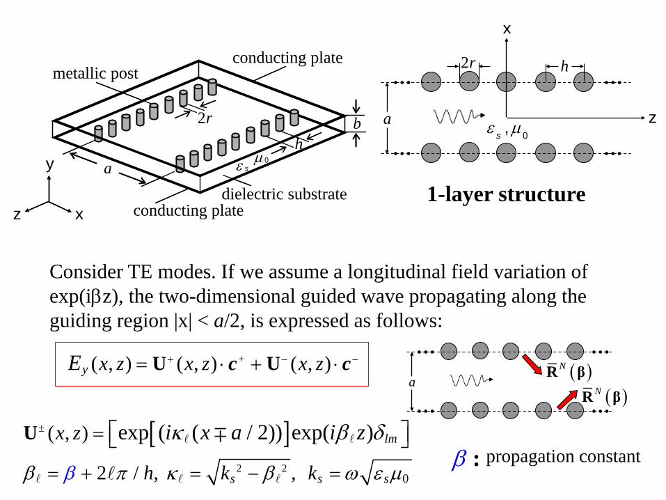
z
x
Consider TE modes. If we assume a longitudinal field variation of exp(iβz), the two-dimensional guided wave propagating along the guiding region |x| < a/2, is expressed as follows:
[ ]
+
2 20
( , ) ( , ) ( , )
( , )
2 / , ,
exp ( ( / 2)) exp( )
y
lm
s s s
x z x z x z
x z
h k k
E
i x a i z
β π κ β ωβ ε µ
κ β δ
+ − −
±
= ⋅ + ⋅
=
= + = − =
U U
U � �
� � ��
∓
c ca
β : propagation constant
( )NR β
( )NR β
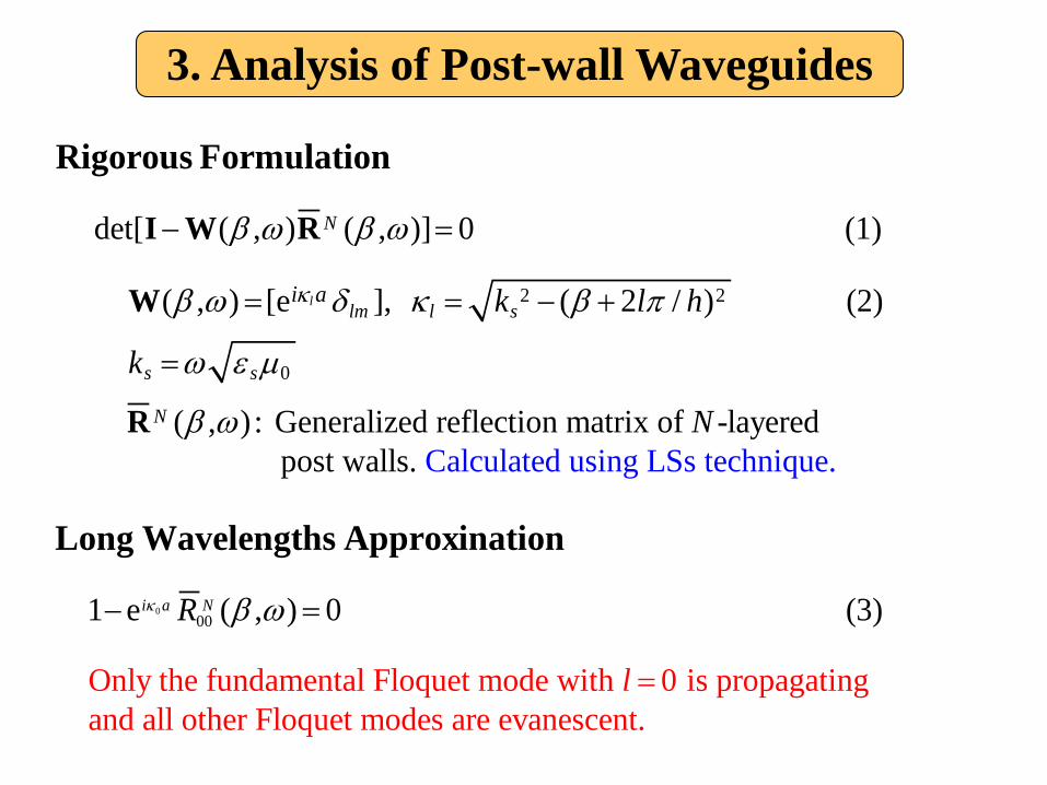
2 2
0
det[ ( , ) ( , )] 0 (1)
( , ) [e ], ( 2 / ) (2)
( , ) : Generalized r
l
N
lm l s
s s
N
i a k l h
k
κ
β ω β ω
β ω δ κ β π
ω ε µ
β ω
− =
= = − +
=
I W R
W
R
Rigorous Formulation
000
Calculated using LSs technieflection matrix of -layered
post walls.
1 e ( , ) 0
qu
.
e
i a N
N
Rκ β ω− =
Long Wavelengths Approxination
Only the fundamental Floquet mode with 0 is propagating and all other Floquet mo
(3)
des are evanesce
nt. l =
3. Analysis of Post-wall Waveguides
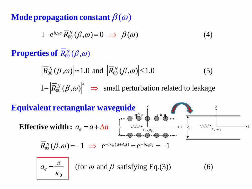
0
00
00
00 00
1 e ( , ) 0 ( ) (4)
( , ) 1.0 and ( , ) 1.0 (5)
( , )
(
)Ni a
N
N
N
R
R
R
R
κ β ω β ω
β ω β ω
β ω
β ω
− =
≤
⇒
Mode propagation constant
Properties of
�
0 000
200
( )
1 ( , ) small perturbation related to leakage
( , ) 1 e e 1
N e
N
i a a i a
e
R
a a
R
a
κ κ
β ω
β ω − +∆ −
−
= +
= − = = −
⇒
⇒
∆ Effective width:
Equivalent rectangular waveguide
0 (for and satisfying Eq.(3)) (6) ea π ω β
κ=
a
h2r
ε µ0,s
z
x
ea ε µ0,s
z
x
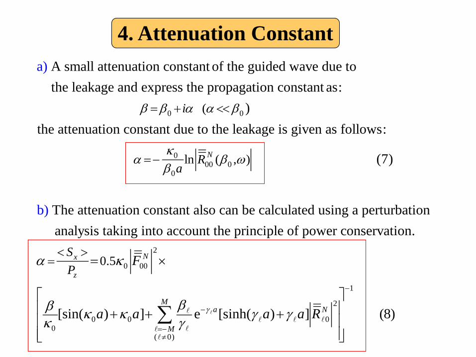
4. Attenuation Constant
0 0
0
0
(
A small attenuation constant of the guided wave due to the leakage and express the propagation constant as:
)the attenuation constant due to the leakage is given as follows:
a)
i
a
β β α α β
κα
β
= + <<
=− 00 0
2
0 00
0 00
ln ( , )
0.5
(7)
The attenuation constant also can be calculated using a perturbation analysis taking into account the principle of power conservatb)
ion.
[sin( ) ] e
N
Nx
z
R
SP
F
a a
β ω
α κ
ββ κ κκ γ
< >= = ×
+ + �
�
1
2
0
( 0)
[sinh( ) ] (8)M
a N
Ma a Rγ γ γ
−
−
=−≠
+
∑ �� � �
��
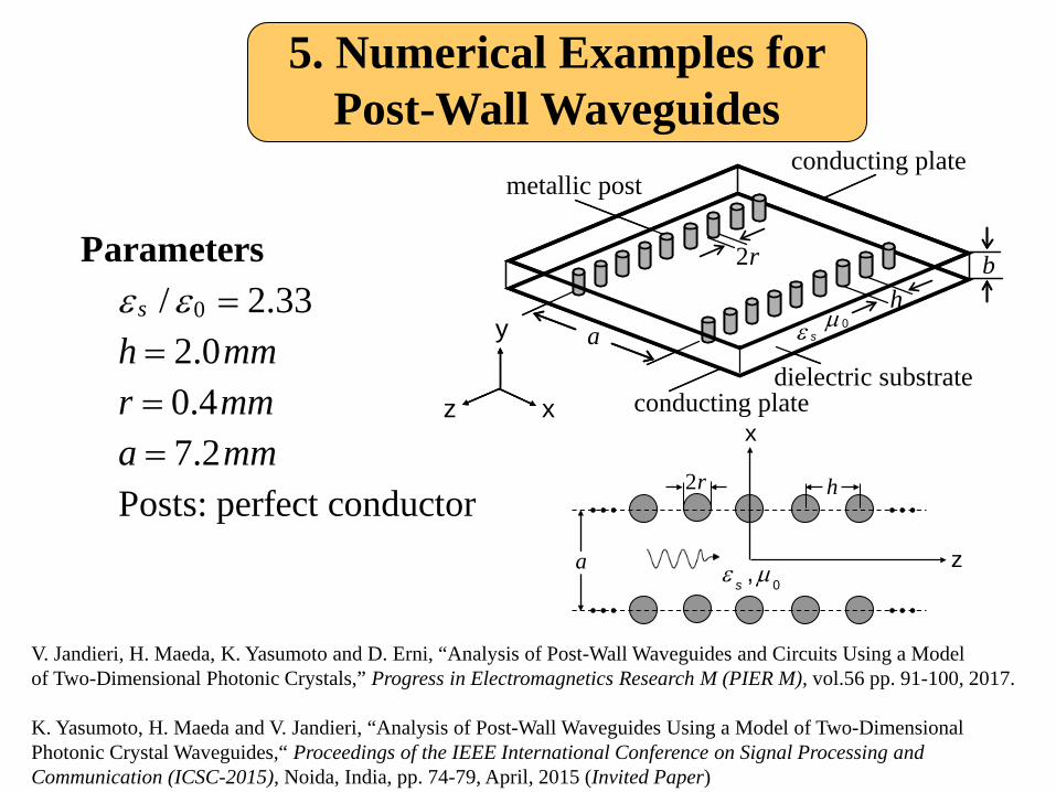
5. Numerical Examples for Post-Wall Waveguides
0
/ 2.33 2.0 0.4 7.2 Posts: perfect conductor
s
h mmr mma mm
ε ε ====
Parameters
a
h2r
ε µ0,s
z
x
V. Jandieri, H. Maeda, K. Yasumoto and D. Erni, “Analysis of Post-Wall Waveguides and Circuits Using a Model of Two-Dimensional Photonic Crystals,” Progress in Electromagnetics Research M (PIER M), vol.56 pp. 91-100, 2017.
K. Yasumoto, H. Maeda and V. Jandieri, “Analysis of Post-Wall Waveguides Using a Model of Two-Dimensional Photonic Crystal Waveguides,“ Proceedings of the IEEE International Conference on Signal Processing and Communication (ICSC-2015), Noida, India, pp. 74-79, April, 2015 (Invited Paper)
conducting plate
conducting platedielectric substrate
metallic post
z x
y
bh
a
2r
µ 0ε s
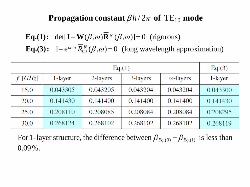
0 00
10
det[ ( , ) ( , )] 0 (rigorous) 1 e ( , ) 0 (long wavelength approximation)
/ 2 TE
N
Ni a R
h
κ
β ω β ωβ ω
β π
− =
− =
Eq.(1): I W REq.(3):
Propagation constant of mode
.(3) .(1)For 1- layer structure, the difference between is less than0.09%.
Eq Eqβ β−
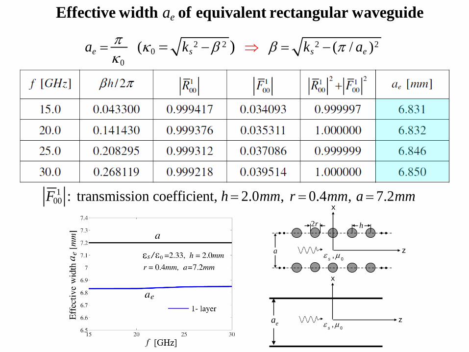
100 : transmission coefficient, 2.0 , 0.4 , 7.2 F h mm r mm a mm= = =
2 2 2 20
0( ( / ))e s s e
e
a k k a
aπ κ β β πκ
⇒= − = −=
Effective width of equivalent rectangular waveguide
a
h2r
ε µ0,s
z
x
ea ε µ0,s
z
x
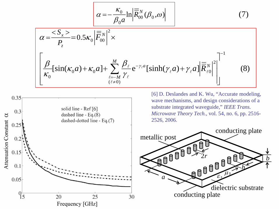
[6] D. Deslandes and K. Wu, “Accurate modeling, wave mechanisms, and design considerations of a substrate integrated waveguide,” IEEE Trans. Microwave Theory Tech., vol. 54, no. 6, pp. 2516-2526, 2006.
000 0
0
2
0 00
1
2
0 0 00
( 0)
ln ( , )
0.5
(7)
[sin( ) ] e [sinh( ) ] (8)
N
Nx
z
Ma N
M
Ra
SP
F
a a a a Rγ
κα β ω
β
α κ
ββ κ κ γ γκ γ
−
−
=−≠
=−
< >= = ×
+ + +
∑ ��� � �
���
conducting plate
conducting platedielectric substrate
metallic post
bh
a
2r
µ 0ε s
0
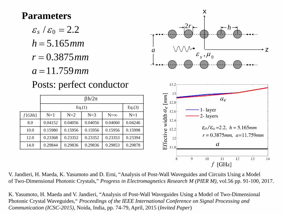
/ 2.2 5.165 0.3875 11.759 Posts: perfect conductor
ε ε ====
s
h mmr mma mm
Parameters
a
h2r
ε µ0,s
z
x
βh/2πEq.(1) Eq.(3)
f [GHz] N=1 N=2 N=3 N=∞ N=18.0 0.04152 0.04056 0.04056 0.04060 0.04246
10.0 0.15980 0.15956 0.15956 0.15956 0.15998
12.0 0.23368 0.23352 0.23352 0.23353 0.23394
14.0 0.29844 0.29836 0.29836 0.29853 0.29878
V. Jandieri, H. Maeda, K. Yasumoto and D. Erni, “Analysis of Post-Wall Waveguides and Circuits Using a Model of Two-Dimensional Photonic Crystals,” Progress in Electromagnetics Research M (PIER M), vol.56 pp. 91-100, 2017.
K. Yasumoto, H. Maeda and V. Jandieri, “Analysis of Post-Wall Waveguides Using a Model of Two-Dimensional Photonic Crystal Waveguides,“ Proceedings of the IEEE International Conference on Signal Processing and Communication (ICSC-2015), Noida, India, pp. 74-79, April, 2015 (Invited Paper)
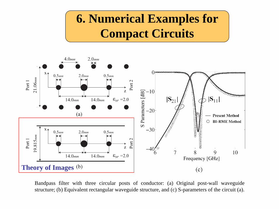
6. Numerical Examples for Compact Circuits
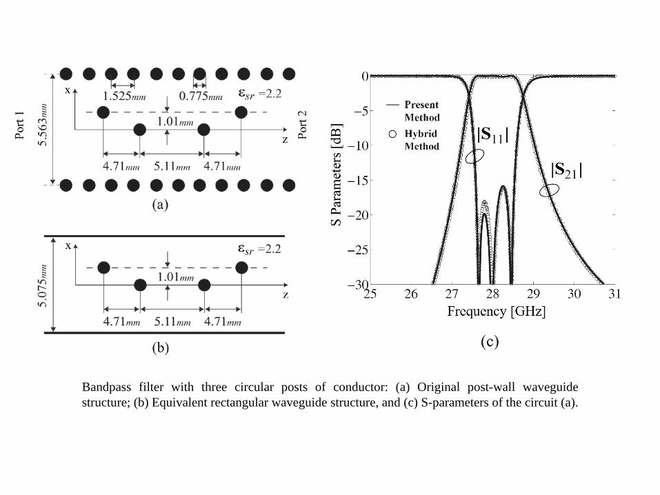
Bandpass filter with three circular posts of conductor: (a) Original post-wall waveguidestructure; (b) Equivalent rectangular waveguide structure, and (c) S-parameters of the circuit (a).
Theory of Images
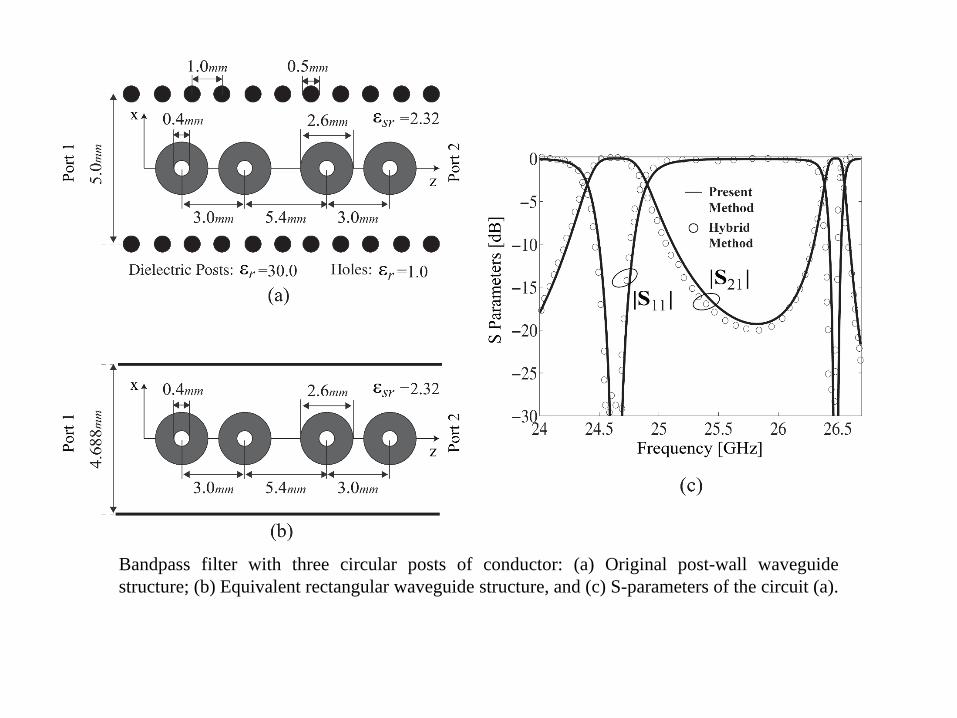
Bandpass filter with three circular posts of conductor: (a) Original post-wall waveguidestructure; (b) Equivalent rectangular waveguide structure, and (c) S-parameters of the circuit (a).
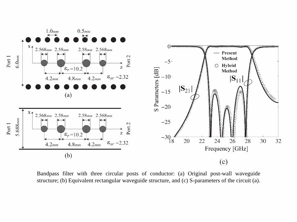
Bandpass filter with three circular posts of conductor: (a) Original post-wall waveguidestructure; (b) Equivalent rectangular waveguide structure, and (c) S-parameters of the circuit (a).
Bandpass filter with three circular posts of conductor: (a) Original post-wall waveguidestructure; (b) Equivalent rectangular waveguide structure, and (c) S-parameters of the circuit (a).
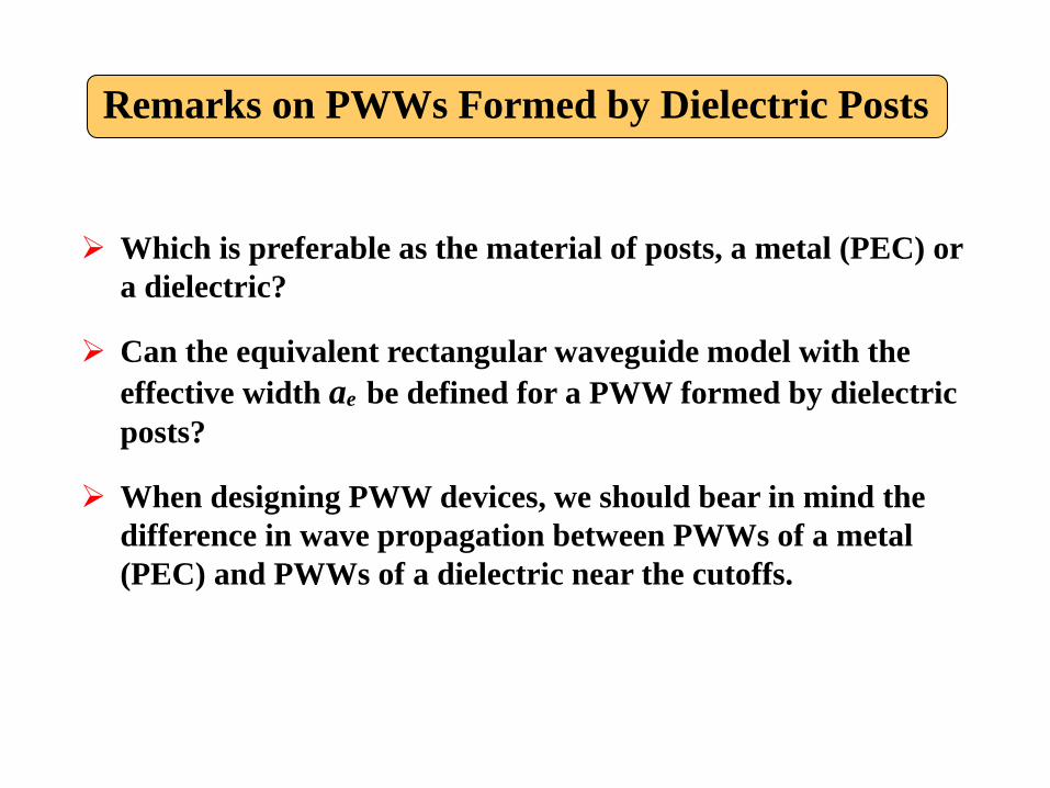
Remarks on PWWs Formed by Dielectric Posts
Which is preferable as the material of posts, a metal (PEC) or a dielectric?
Can the equivalent rectangular waveguide model with the effective width ae be defined for a PWW formed by dielectric posts?
When designing PWW devices, we should bear in mind the difference in wave propagation between PWWs of a metal (PEC) and PWWs of a dielectric near the cutoffs.
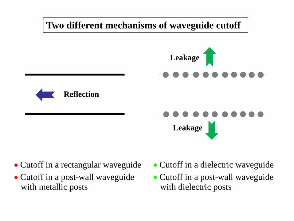
Reflection
Leakage
Leakage
Cutoff in a rectangular waveguideCutoff in a post-wall waveguide
with metallic posts
••
Cutoff in a dielectric waveguideCutoff in a post-wall waveguide
with dielectric posts
••
Two different mechanisms of waveguide cutoff
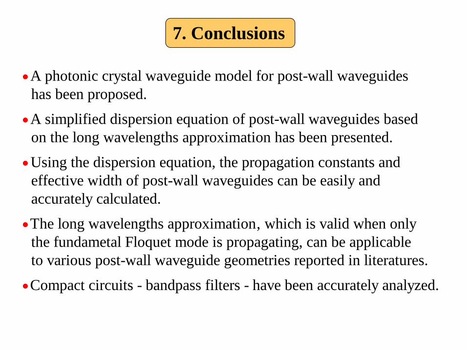
7. Conclusions
A photonic crystal waveguide model for post-wall waveguides has been proposed.A simplified dispersion equation of post-wall waveguides based
on the long wavelengths approximation has been presente
•
•d.
Using the dispersion equation, the propagation constants and effective width of post-wall waveguides can be easily and accurately calculated.The long wavelengths approximation, which is valid w
•
• hen only the fundametal Floquet mode is propagating, can be applicable to various post-wall waveguide geometries reported in literatures.Compact circuits - bandpass filters - have been accurately a• nalyzed.

Thank you very much