MOBILE ELECTRONICS - Poclain
108
MOBILE ELECTRONICS T E C H N I C A L C A T A L O G
Transcript of MOBILE ELECTRONICS - Poclain

M O B ILEE LE C TR O N IC S
T E C H N I C A L C A T A L O G
Mobile electronics POCLAIN HYDRAULICS
2 23/11/2017
Methodology :This document is intended for manufacturers of machines that incorporate Poclain Hydraulics products. It describes the technical characteristics of Poclain Hydraulics products and specifies installation conditions that will ensure optimum operation. This document includes important comments concerning safety. They are indicated in the following way:
This document also includes essential operating instructions for the product and general information. These are indicated in the following way:
The views in this document are created using metric standards. The dimensional data is given in mm and in inches (inches are between brackets and italic)
Associated documents
Safety comment.
Essential instructions.
General information .
Information on the model number.Information on the mo-del code.
Weight of component without oil.
Volume of oil.
Units.
Tightening torque.
Screws.
Information intended for Poclain-Hydraulics personnel.
Document typeGeneric installation 801478197L
The components of this booklet are not reparable.
Warranty reclaim of any disassembled components will not be accepted.
23/11/2017 3
CONTENTPOCLAIN HYDRAULICS Mobile electronics
Elec
tron
ic c
ontr
ol u
nits
Elec
tron
ic c
ompo
nent
sC
onne
ctor
sC
able
sD
ispl
ays
Electronic Control Units 4SmartDrive™ Easy ECU 5SmartDrive™ CT ECU 8SmartDrive™ Premier, Master, Offroad ECU 11
Displays 15Display 1.5 15Display 4.3C 17
19
Connectors 62SmartDrive™ Easy main connector 62SmartDrive Premier, Master, Offroad main connector 63SmartDrive™Communication connector 65SmartDrive™ Male communication connector 66SmartDrive™ CT main connector 68SmartDrive™ CT communication connector 70Connector kit 120 72Display 4.3C main connector 743-pin Weather Pack connector 753-pin Metri Pack connector 766-pin Metri Pack connector 77EN 175301 - 803 style A Connector 78EN 175301 - 803 style A Connector with diode 792-pin AMP Timer Junior connector 812-pin Deutsch connector 823-pin Deutsch connector 834-pin Deutsch connector 84Connector actuator 854-pin DIN72585 IP6K9K connector 86Inclinometer connector 88
Electronic components 19Speed sensor T4 19Speed sensor TR 21Speed sensor TD 23Magnetic incremental hollow shaft encoder 25Inclinometer 27Rotary potentiometer 2920 bar pressure sensor 3140 bar pressure sensor 3340 bar pressure sensor IP6K9K 35160 bar pressure sensor 37160 bar pressure sensor IP6K9K 39600 bar pressure sensor 41600 bar pressure sensor IP6K9K 43Digital sensors 45Analog temperature sensors 47Thermocontact 51Joystick with center lock 53Joystick with Z gate 55Electronic Travel pedal 57Travel / brake suspended pedal 60
Cables 90SmartDrive™ Easy cable 90SmartDrive™ Master cable 91SmartDrive™ Off-Road cable 92SmartDrive™ CT cable 93SmartDrive™ CT test cable 94SmartDrive™ PWe test cable 96SmartDrive™ EASY test cable 98SmartDrive™ communication cable 100Pressure sensors cable 1014-pin M12 cable 1025-pin M12 cable 1035-pin M12 120 ohm cable 1041 signal pedal connection cable 1052 signal pedal connection cable 106

4 23/11/2017
Mobile electronics POCLAIN HYDRAULICS
Electronic Control Units
23/11/2017 5
POCLAIN HYDRAULICS Mobile electronics
Elec
tron
ic c
ontr
ol u
nits
Elec
tron
ic c
ompo
nent
sC
onne
ctor
sC
able
sD
ispl
ays
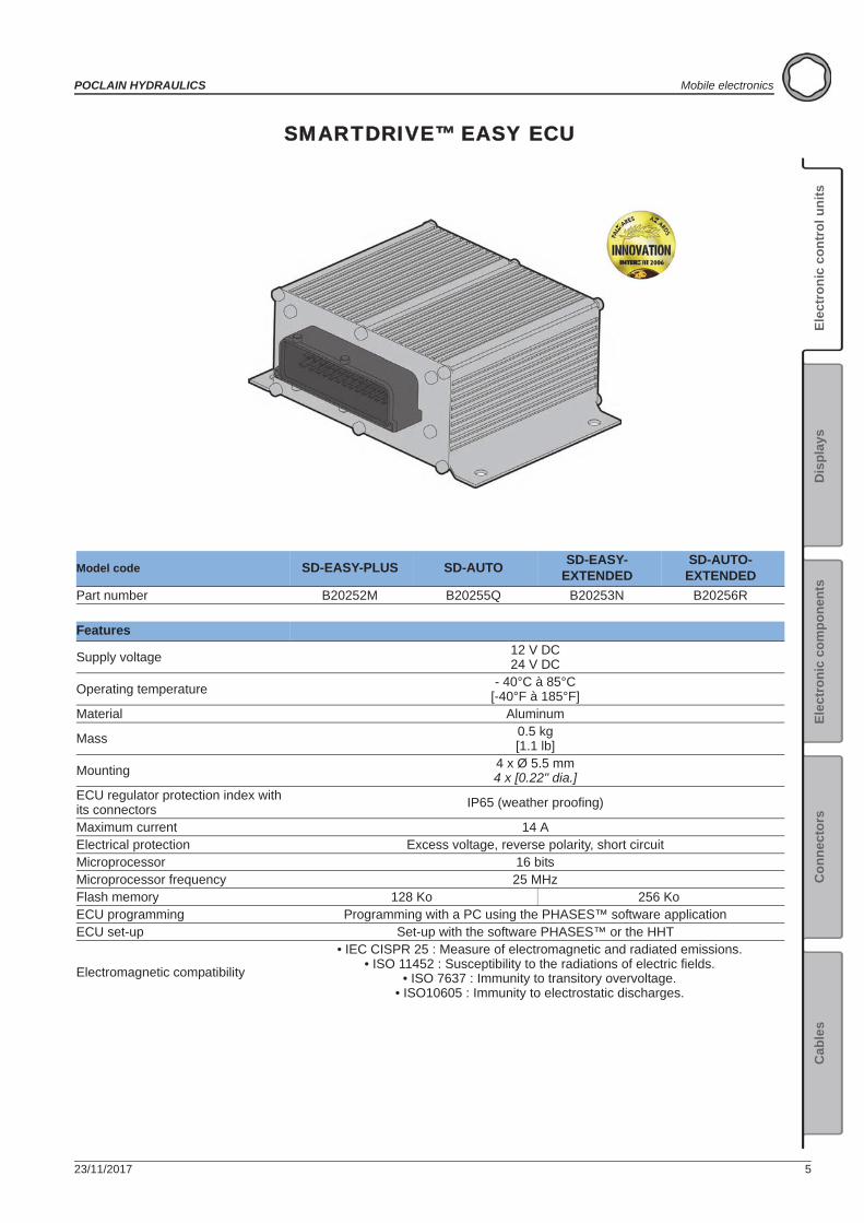
SMARTDRIVE™ EASY ECU
Model code SD-EASY-PLUS SD-AUTO SD-EASY-EXTENDED
SD-AUTO-EXTENDED
Part number B20252M B20255Q B20253N B20256R
Features
Supply voltage 12 V DC24 V DC
Operating temperature - 40°C à 85°C[-40°F à 185°F]
Material Aluminum
Mass 0.5 kg[1.1 lb]
Mounting 4 x Ø 5.5 mm4 x [0.22" dia.]
ECU regulator protection index with its connectors IP65 (weather proofing)
Maximum current 14 AElectrical protection Excess voltage, reverse polarity, short circuitMicroprocessor 16 bitsMicroprocessor frequency 25 MHzFlash memory 128 Ko 256 KoECU programming Programming with a PC using the PHASES™ software applicationECU set-up Set-up with the software PHASES™ or the HHT
Electromagnetic compatibility
• IEC CISPR 25 : Measure of electromagnetic and radiated emissions.• ISO 11452 : Susceptibility to the radiations of electric fields.
• ISO 7637 : Immunity to transitory overvoltage.• ISO10605 : Immunity to electrostatic discharges.
6 23/11/2017
Mobile electronics POCLAIN HYDRAULICS
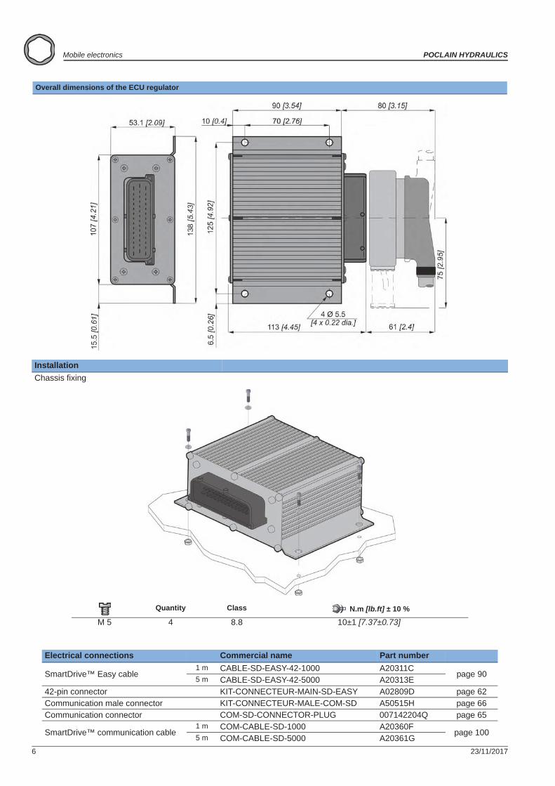
Overall dimensions of the ECU regulator
InstallationChassis fixing
Quantity Class N.m [lb.ft] ± 10 %
M 5 4 8.8 10±1 [7.37±0.73]
Electrical connections Commercial name Part number
SmartDrive™ Easy cable1 m CABLE-SD-EASY-42-1000 A20311C
page 905 m CABLE-SD-EASY-42-5000 A20313E
42-pin connector KIT-CONNECTEUR-MAIN-SD-EASY A02809D page 62Communication male connector KIT-CONNECTEUR-MALE-COM-SD A50515H page 66Communication connector COM-SD-CONNECTOR-PLUG 007142204Q page 65
SmartDrive™ communication cable1 m COM-CABLE-SD-1000 A20360F
page 1005 m COM-CABLE-SD-5000 A20361G

23/11/2017 7
POCLAIN HYDRAULICS Mobile electronics
Elec
tron
ic c
ontr
ol u
nits
Elec
tron
ic c
ompo
nent
sC
onne
ctor
sC
able
sD
ispl
ays
8 23/11/2017
Mobile electronics POCLAIN HYDRAULICS
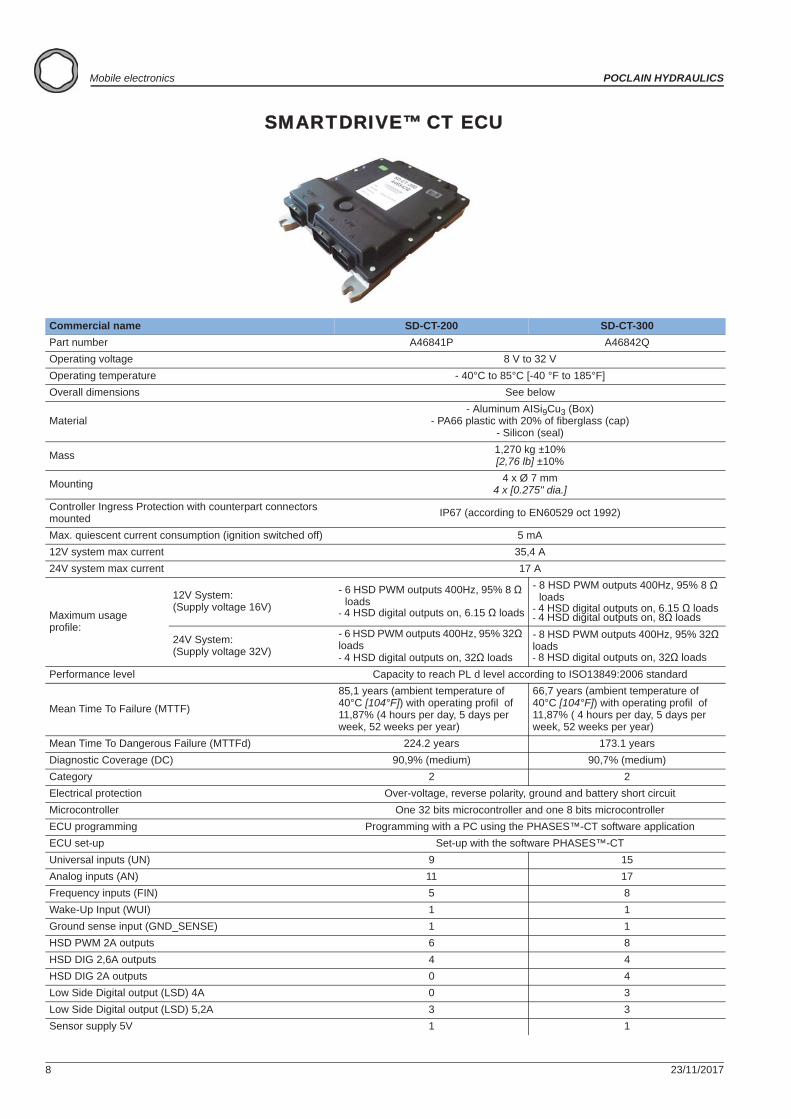
SMARTDRIVE™ CT ECU
Commercial name SD-CT-200 SD-CT-300Part number A46841P A46842QOperating voltage 8 V to 32 VOperating temperature - 40°C to 85°C [-40 °F to 185°F]Overall dimensions See below
Material- Aluminum AISi9Cu3 (Box)
- PA66 plastic with 20% of fiberglass (cap)- Silicon (seal)
Mass 1,270 kg ±10%[2,76 lb] ±10%
Mounting 4 x Ø 7 mm4 x [0.275" dia.]
Controller Ingress Protection with counterpart connectors mounted IP67 (according to EN60529 oct 1992)
Max. quiescent current consumption (ignition switched off) 5 mA12V system max current 35,4 A24V system max current 17 A
Maximum usageprofile:
12V System:(Supply voltage 16V)
- 6 HSD PWM outputs 400Hz, 95% 8 loads
- 4 HSD digital outputs on, 6.15 loads
- 8 HSD PWM outputs 400Hz, 95% 8 loads
- 4 HSD digital outputs on, 6.15 loads- 4 HSD digital outputs on, 8 loads
24V System:(Supply voltage 32V)
- 6 HSD PWM outputs 400Hz, 95% 32 loads- 4 HSD digital outputs on, 32 loads
- 8 HSD PWM outputs 400Hz, 95% 32 loads- 8 HSD digital outputs on, 32 loads
Performance level Capacity to reach PL d level according to ISO13849:2006 standard
Mean Time To Failure (MTTF)
85,1 years (ambient temperature of 40°C [104°F]) with operating profil of 11,87% (4 hours per day, 5 days per week, 52 weeks per year)
66,7 years (ambient temperature of 40°C [104°F]) with operating profil of 11,87% ( 4 hours per day, 5 days per week, 52 weeks per year)
Mean Time To Dangerous Failure (MTTFd) 224.2 years 173.1 yearsDiagnostic Coverage (DC) 90,9% (medium) 90,7% (medium)Category 2 2Electrical protection Over-voltage, reverse polarity, ground and battery short circuitMicrocontroller One 32 bits microcontroller and one 8 bits microcontrollerECU programming Programming with a PC using the PHASES™-CT software applicationECU set-up Set-up with the software PHASES™-CTUniversal inputs (UN) 9 15Analog inputs (AN) 11 17Frequency inputs (FIN) 5 8Wake-Up Input (WUI) 1 1Ground sense input (GND_SENSE) 1 1HSD PWM 2A outputs 6 8HSD DIG 2,6A outputs 4 4HSD DIG 2A outputs 0 4Low Side Digital output (LSD) 4A 0 3Low Side Digital output (LSD) 5,2A 3 3Sensor supply 5V 1 1
23/11/2017 9
POCLAIN HYDRAULICS Mobile electronics
Elec
tron
ic c
ontr
ol u
nits
Elec
tron
ic c
ompo
nent
sC
onne
ctor
sC
able
sD
ispl
ays
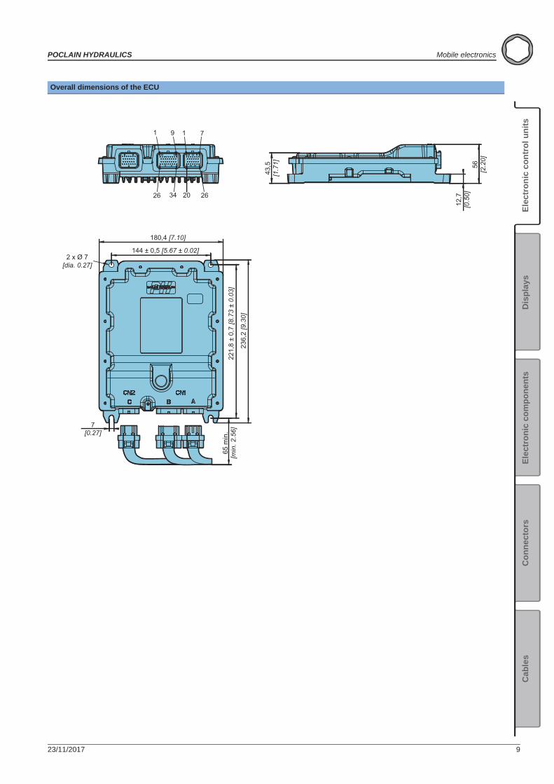
Overall dimensions of the ECU
1 9
26 34
1 7
20 26
2 x Ø 7[dia. 0.27]
43,5
[1.7
1]
12,7
[0.5
0]56
[2.2
0]
180,4 [7.10]22
1,8
± 0,
7 [8
.73
± 0.
03]
236,
2 [9
.30]
65 m
in.
[min
. 2.5
6]
144 ± 0,5 [5.67 ± 0.02]
7[0.27]
10 23/11/2017
Mobile electronics POCLAIN HYDRAULICS
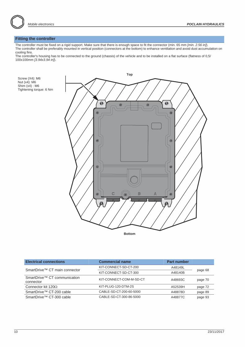
Fitting the controllerThe controller must be fixed on a rigid support. Make sure that there is enough space to fit the connector (min. 65 mm [min. 2.56 in]).The controller shall be preferably mounted in vertical position (connectors at the bottom) to enhance ventilation and avoid dust accumulation on cooling fins.The controller's housing has to be connected to the ground (chassis) of the vehicle and to be installed on a flat surface (flatness of 0,5/100x100mm [3.94x3.94 in]).
Electrical connections Commercial name Part number
SmartDrive™ CT main connectorKIT-CONNECT-SD-CT-200 A48149L
page 68KIT-CONNECT-SD-CT-300 A48140B
SmartDrive™ CT communication connector KIT-CONNECT-COM-M-SD-CT A48693C page 70
Connector kit 120 KIT-PLUG-120-DTM-2S A52539H page 72SmartDrive™ CT-200 cable CABLE-SD-CT-200-60-5000 A48878D page 89SmartDrive™ CT-300 cable CABLE-SD-CT-300-86-5000 A48877C page 93
Screw (X4): M6Nut (x4): M6Shim (x4) : M6Tightening torque: 6 Nm
Top
Bottom
23/11/2017 11
POCLAIN HYDRAULICS Mobile electronics
Elec
tron
ic c
ontr
ol u
nits
Elec
tron
ic c
ompo
nent
sC
onne
ctor
sC
able
sD
ispl
ays
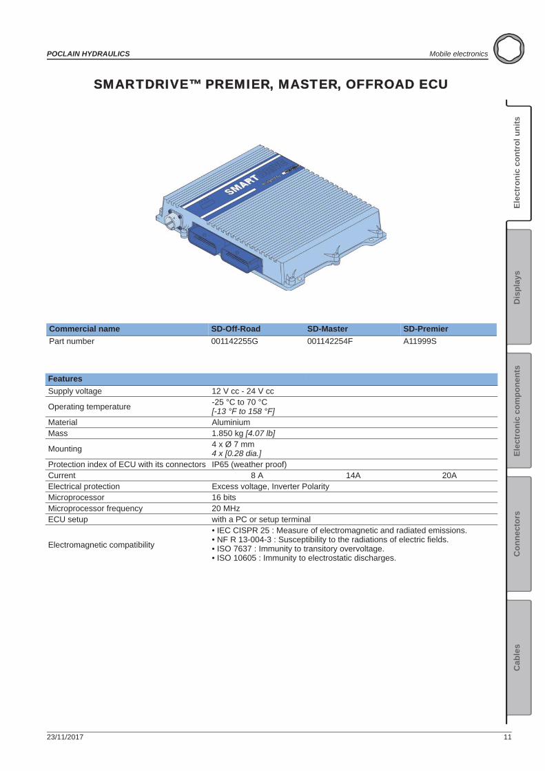
SMARTDRIVE™ PREMIER, MASTER, OFFROAD ECU
Commercial name SD-Off-Road SD-Master SD-PremierPart number 001142255G 001142254F A11999S
FeaturesSupply voltage 12 V cc - 24 V cc
Operating temperature -25 °C to 70 °C[-13 °F to 158 °F]
Material AluminiumMass 1.850 kg [4.07 lb]
Mounting 4 x Ø 7 mm 4 x [0.28 dia.]
Protection index of ECU with its connectors IP65 (weather proof)Current 8 A 14A 20AElectrical protection Excess voltage, Inverter PolarityMicroprocessor 16 bitsMicroprocessor frequency 20 MHzECU setup with a PC or setup terminal
Electromagnetic compatibility
• IEC CISPR 25 : Measure of electromagnetic and radiated emissions.• NF R 13-004-3 : Susceptibility to the radiations of electric fields.• ISO 7637 : Immunity to transitory overvoltage.• ISO 10605 : Immunity to electrostatic discharges.
12 23/11/2017
Mobile electronics POCLAIN HYDRAULICS
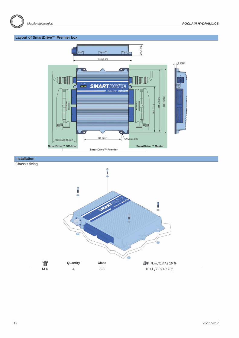
Layout of SmartDrive™ Premier box
InstallationChassis fixing
Quantity Class N.m [lb.ft] ± 10 %
M 6 4 8.8 10±1 [7.37±0.73]
23/11/2017 13
POCLAIN HYDRAULICS Mobile electronics
Elec
tron
ic c
ontr
ol u
nits
Elec
tron
ic c
ompo
nent
sC
onne
ctor
sC
able
sD
ispl
ays
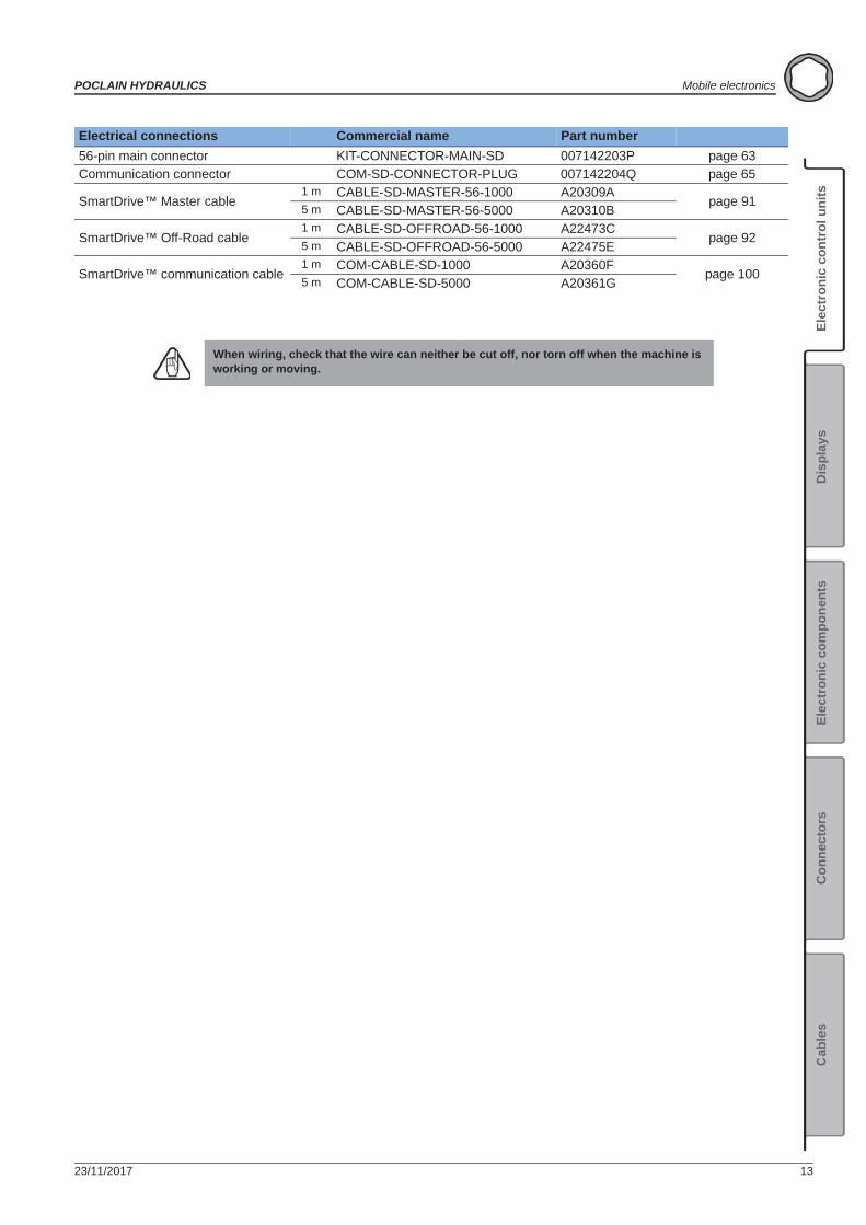
Electrical connections Commercial name Part number56-pin main connector KIT-CONNECTOR-MAIN-SD 007142203P page 63Communication connector COM-SD-CONNECTOR-PLUG 007142204Q page 65
SmartDrive™ Master cable1 m CABLE-SD-MASTER-56-1000 A20309A
page 915 m CABLE-SD-MASTER-56-5000 A20310B
SmartDrive™ Off-Road cable1 m CABLE-SD-OFFROAD-56-1000 A22473C
page 925 m CABLE-SD-OFFROAD-56-5000 A22475E
SmartDrive™ communication cable1 m COM-CABLE-SD-1000 A20360F
page 1005 m COM-CABLE-SD-5000 A20361G
When wiring, check that the wire can neither be cut off, nor torn off when the machine is working or moving.

14 23/11/2017
Mobile electronics POCLAIN HYDRAULICS
23/11/2017 15
POCLAIN HYDRAULICS Mobile electronics
Elec
tron
ic c
ontr
ol u
nits
Elec
tron
ic c
ompo
nent
sC
onne
ctor
sC
able
sD
ispl
ays
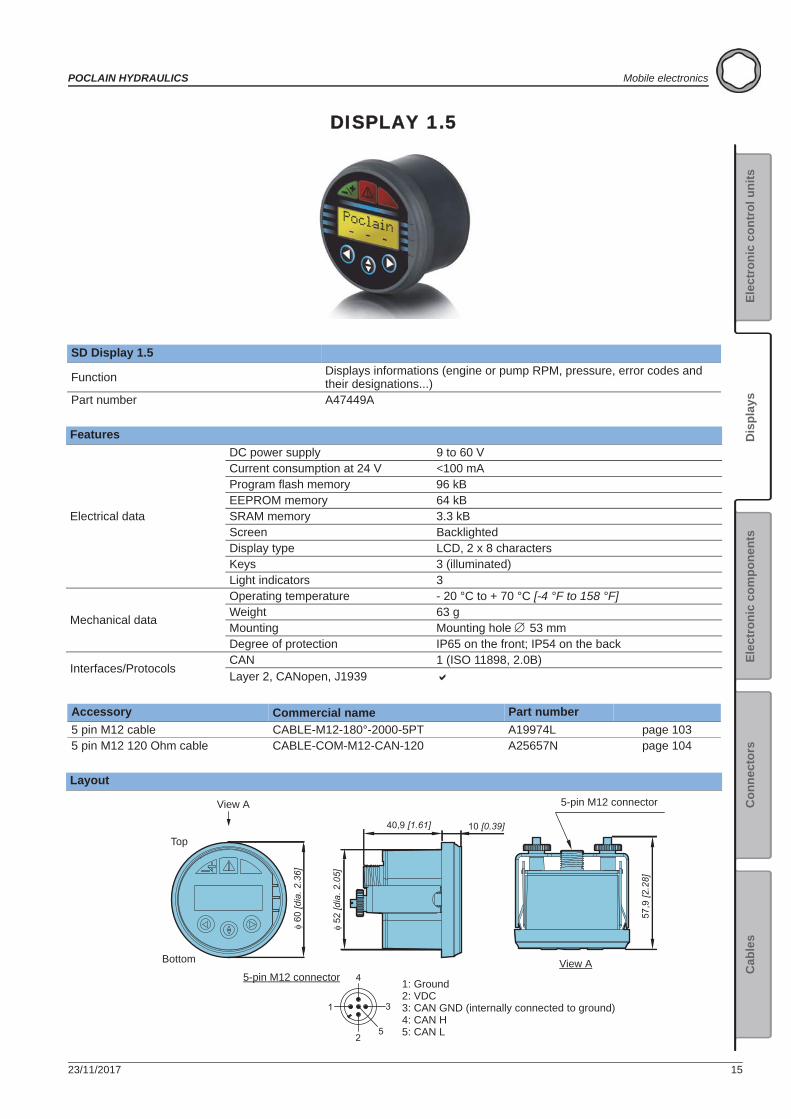
DISPLAY 1.5
SD Display 1.5
Function Displays informations (engine or pump RPM, pressure, error codes and their designations...)
Part number A47449A
Features
Electrical data
DC power supply 9 to 60 VCurrent consumption at 24 V <100 mAProgram flash memory 96 kBEEPROM memory 64 kBSRAM memory 3.3 kBScreen BacklightedDisplay type LCD, 2 x 8 charactersKeys 3 (illuminated)Light indicators 3
Mechanical data
Operating temperature - 20 °C to + 70 °C [-4 °F to 158 °F]Weight 63 gMounting Mounting hole 53 mmDegree of protection IP65 on the front; IP54 on the back
Interfaces/ProtocolsCAN 1 (ISO 11898, 2.0B)Layer 2, CANopen, J1939
Accessory Commercial name Part number5 pin M12 cable CABLE-M12-180°-2000-5PT A19974L page 1035 pin M12 120 Ohm cable CABLE-COM-M12-CAN-120 A25657N page 104
Layout
52 [d
ia. 2
.05]
60
[dia
. 2.3
6]
57,9
[2.2
8]
1
2
3
4
5
10 [0.39]40,9 [1.61]
5-pin M12 connector
1: Ground2: VDC3: CAN GND (internally connected to ground)4: CAN H5: CAN L
Top
Bottom
5-pin M12 connector
View A
View A
Displays

16 23/11/2017
Mobile electronics POCLAIN HYDRAULICS
Description
FunctioningDisplay the Informations and the Parameters
Press the key -------and--------to navigate into the Informations and the Parameters.
When the tuning light signal is off-------the SD Display 1.5 displays an Information (the value can not be changed).
When the tuning light signal is on-------the SD Display 1.5 displays a Parameters (the value can be changed).
Tune the Parameters values
Only the Parameters values can be tuned (the tuning light indicator is on-------).
1 - Press the key-------to enter into the tuning mode.
The tuning light indicator flashes---------.
2 - Press the key--------to increase the value , or the key--------to decrease the value .
3 - Press the key-------to exit from the tuning mode.
The tuning light indicator stops flashing--------(but it still on).
Display the Error(s)
The flashing error light indicator-------indicates the presence of error(s).
1 - Press the key--------to display the errors(s) and--------to come back into the previous error(s).
2 - Press the key--------to display the Informations and the Parameters.
The error light indicator is off-------when the error(s) is(are) corrected.
N° FunctionError light indicator
Tuning light indicator
’’Information’’, ’’Parameter’’ or ’’Error code’’ line
’’Value’’ or ’’Error identification’’ line
’’Previous’’ or ’’Decrease of the value’’ key
’’Enter’’ or ’’Exit’’ key
’’Next’’ or ’’Increase of the value’’ key
Can not be changed Can not be changed Can be changed Can be changed
23/11/2017 17
POCLAIN HYDRAULICS Mobile electronics
Elec
tron
ic c
ontr
ol u
nits
Elec
tron
ic c
ompo
nent
sC
onne
ctor
sC
able
sD
ispl
ays
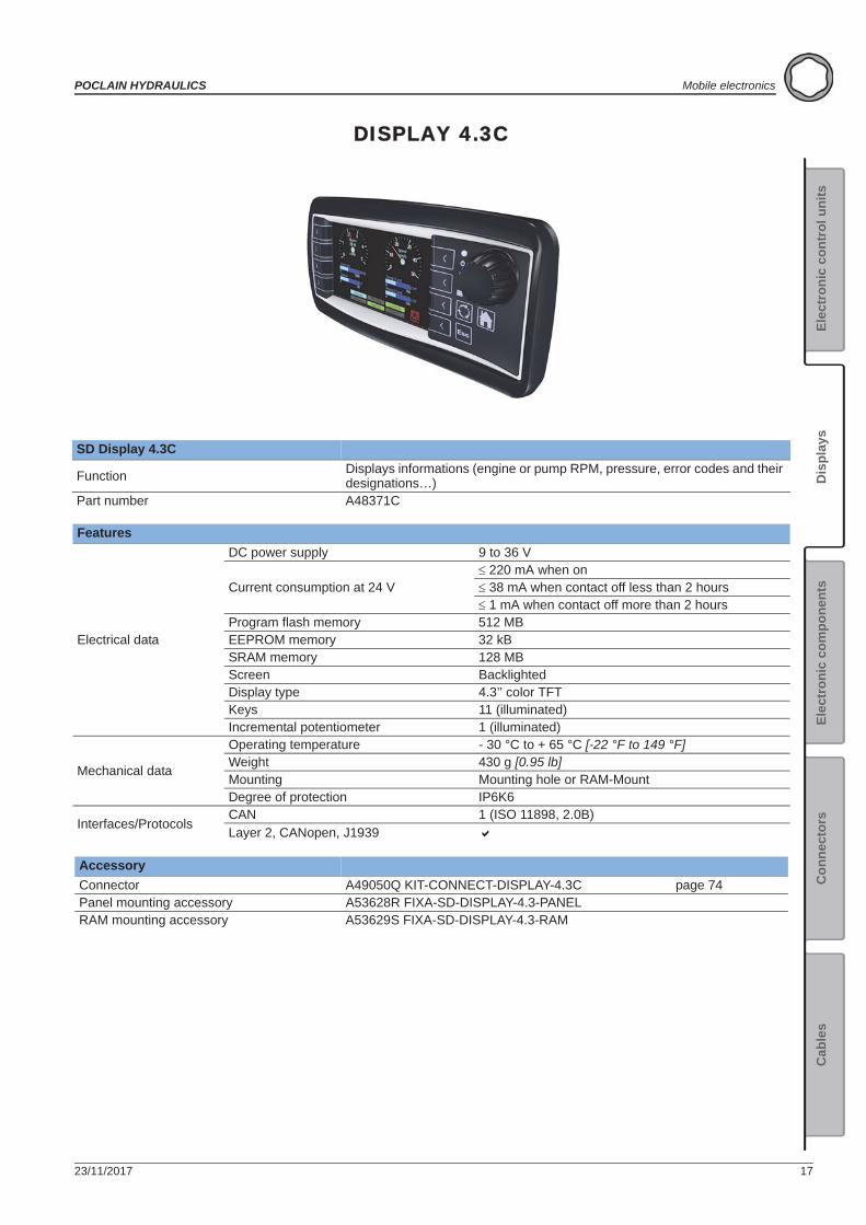
DISPLAY 4.3C
SD Display 4.3C
Function Displays informations (engine or pump RPM, pressure, error codes and their designations…)
Part number A48371C
Features
Electrical data
DC power supply 9 to 36 V
Current consumption at 24 V 220 mA when on 38 mA when contact off less than 2 hours 1 mA when contact off more than 2 hours
Program flash memory 512 MBEEPROM memory 32 kBSRAM memory 128 MBScreen BacklightedDisplay type 4.3’’ color TFT Keys 11 (illuminated)Incremental potentiometer 1 (illuminated)
Mechanical data
Operating temperature - 30 °C to + 65 °C [-22 °F to 149 °F]Weight 430 g [0.95 lb]Mounting Mounting hole or RAM-MountDegree of protection IP6K6
Interfaces/ProtocolsCAN 1 (ISO 11898, 2.0B)Layer 2, CANopen, J1939
Accessory Connector A49050Q KIT-CONNECT-DISPLAY-4.3C page 74Panel mounting accessory A53628R FIXA-SD-DISPLAY-4.3-PANELRAM mounting accessory A53629S FIXA-SD-DISPLAY-4.3-RAM
18 23/11/2017
Mobile electronics POCLAIN HYDRAULICS
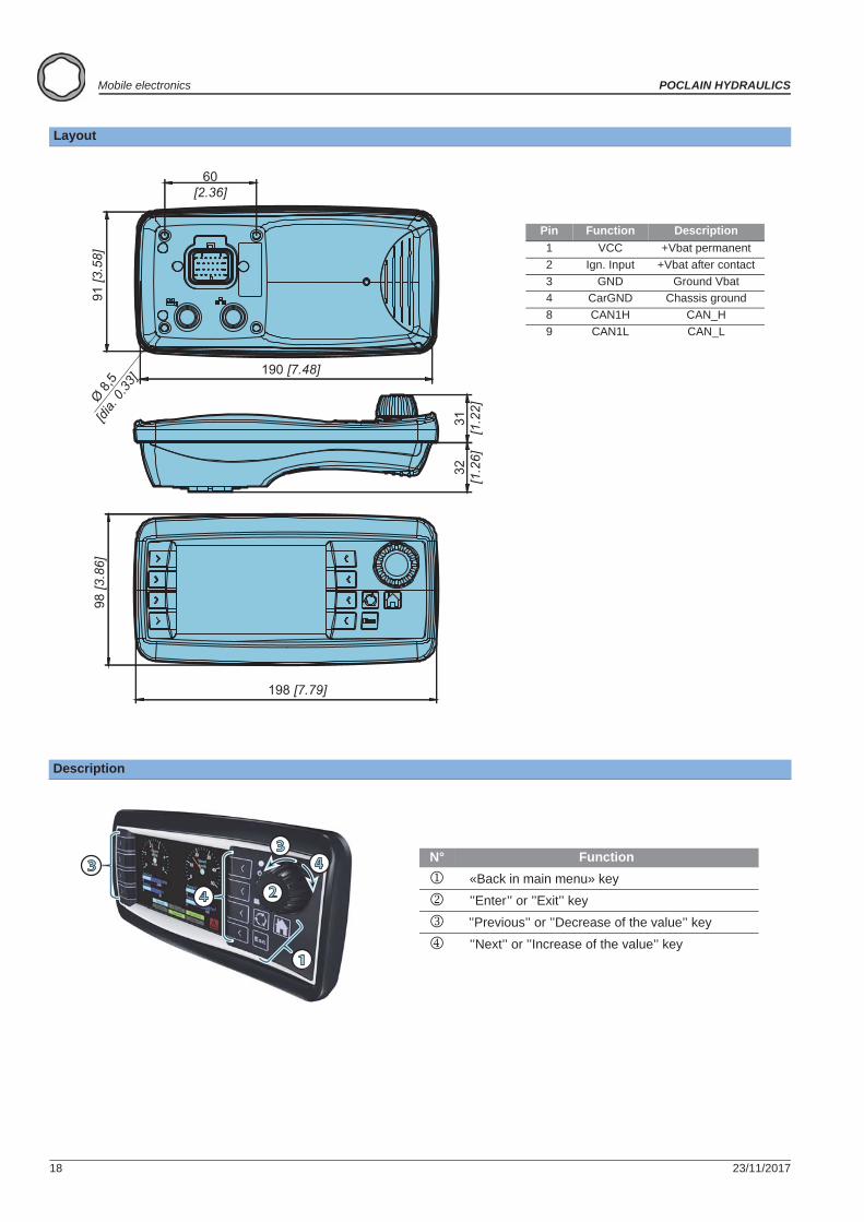
Layout
Description
198 [7.79]
98 [3
.86]
31[1
.22]
32[1
.26]
190 [7.48]
91 [3
.58]
60[2.36]
Ø 8,5
[dia.
0.33]
Pin Function Description1 VCC +Vbat permanent2 Ign. Input +Vbat after contact3 GND Ground Vbat4 CarGND Chassis ground8 CAN1H CAN_H9 CAN1L CAN_L
1
3
4 2
34 N° Function
«Back in main menu» key
’’Enter’’ or ’’Exit’’ key
’’Previous’’ or ’’Decrease of the value’’ key
’’Next’’ or ’’Increase of the value’’ key
23/11/2017 19
POCLAIN HYDRAULICS Mobile electronics
Elec
tron
ic c
ontr
ol u
nits
Elec
tron
ic c
ompo
nent
sC
onne
ctor
sC
able
sD
ispl
ays
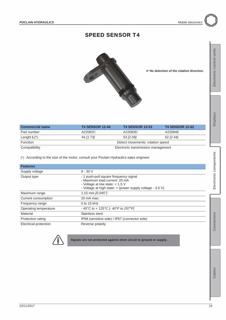
SPEED SENSOR T4
Commercial name T4 SENSOR 12-44 T4 SENSOR 12-53 T4 SENSOR 12-62Part number A22082C A22083D A22084ELenght L(*) 44 [1.73] 53 [2.09] 62 [2.44]Function Detect movements: rotation speedCompatibility Electronic transmission management
(*) : According to the size of the motor, consult your Poclain Hydraulics sales engineer
FeaturesSupply voltage 8 - 30 VOutput type - 1 push-pull square frequency signal
- Maximum load current: 20 mA- Voltage at low state: < 1.5 V- Voltage at high state: > (power supply voltage - 3.5 V)
Maximum range 1.15 mm [0.045’’]Current consumption 20 mA max.Frequency range 0 to 15 kHzOperating temperature - 40°C to + 125°C [- 40°F to 257°F]Material Stainless steelProtection rating IP68 (sensitive side) / IP67 (connector side)Electrical protection Reverse polarity
Signals are not protected against short circuit to ground or supply.
No detection of the rotation direction.
Electronic components
20 23/11/2017
Mobile electronics POCLAIN HYDRAULICS
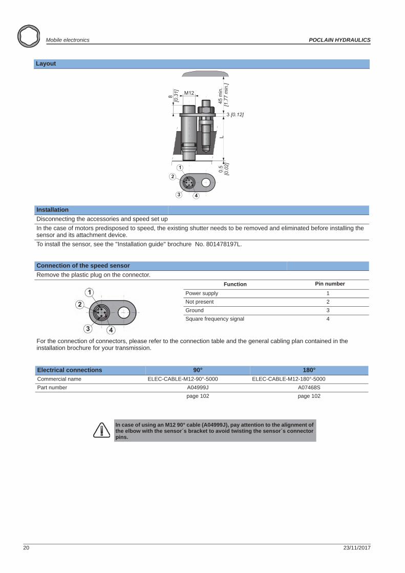
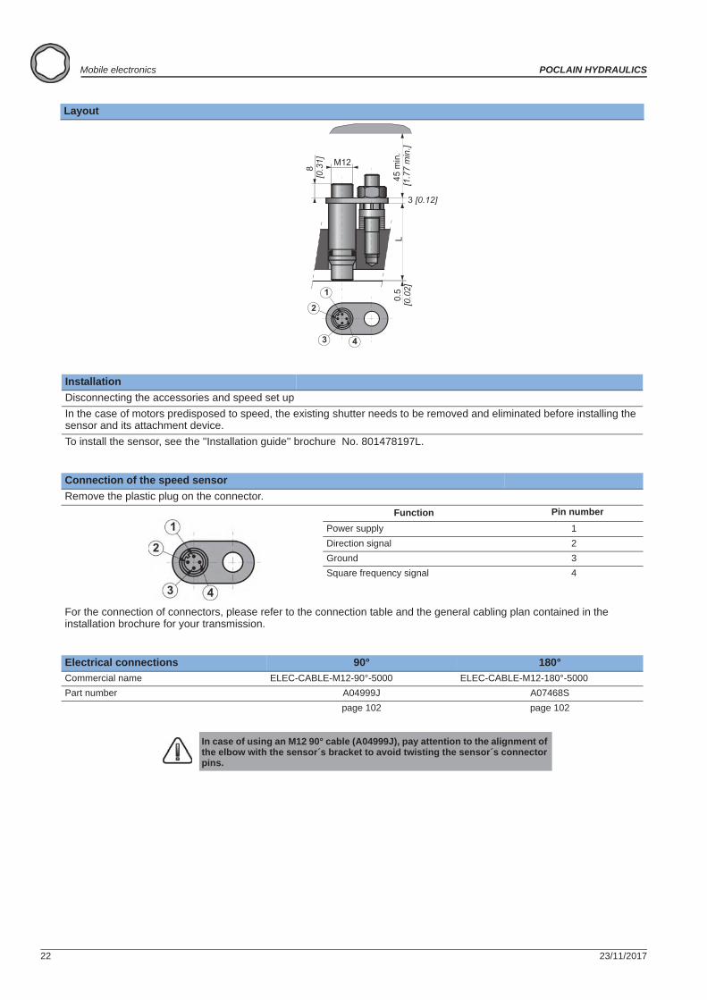
Layout
InstallationDisconnecting the accessories and speed set upIn the case of motors predisposed to speed, the existing shutter needs to be removed and eliminated before installing the sensor and its attachment device.To install the sensor, see the ''Installation guide'' brochure No. 801478197L.
Connection of the speed sensorRemove the plastic plug on the connector.
Function Pin number
Power supply 1Not present 2Ground 3Square frequency signal 4
For the connection of connectors, please refer to the connection table and the general cabling plan contained in the installation brochure for your transmission.
Electrical connections 90° 180°Commercial name ELEC-CABLE-M12-90°-5000 ELEC-CABLE-M12-180°-5000Part number A04999J A07468S
page 102 page 102
In case of using an M12 90° cable (A04999J), pay attention to the alignment of the elbow with the sensor´s bracket to avoid twisting the sensor´s connector pins.
23/11/2017 21
POCLAIN HYDRAULICS Mobile electronics
Elec
tron
ic c
ontr
ol u
nits
Elec
tron
ic c
ompo
nent
sC
onne
ctor
sC
able
sD
ispl
ays
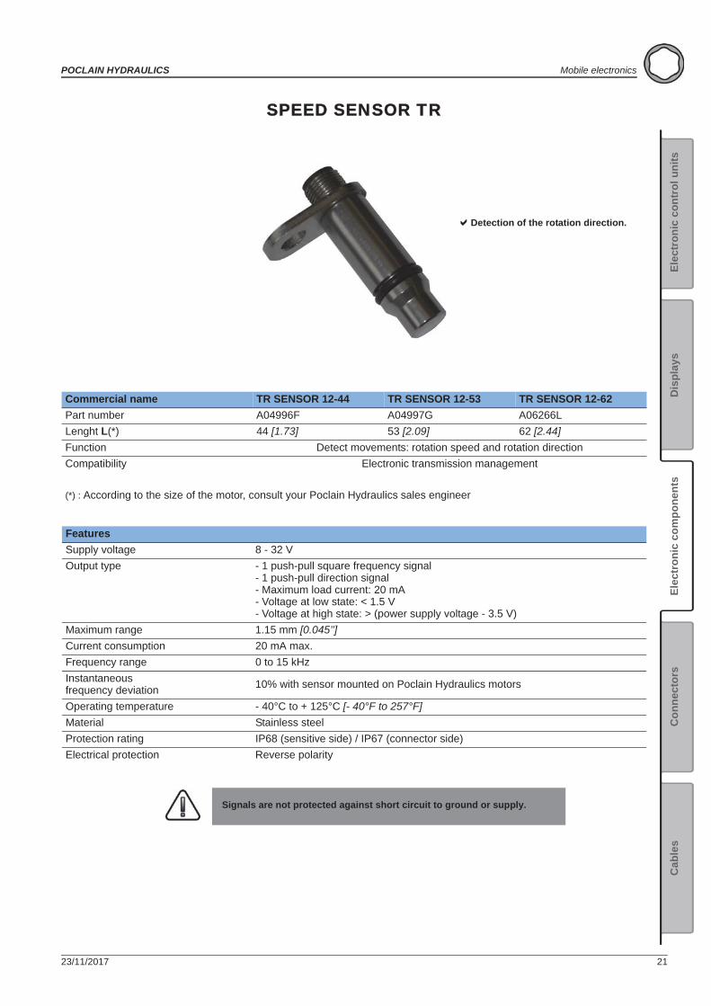
SPEED SENSOR TR
Commercial name TR SENSOR 12-44 TR SENSOR 12-53 TR SENSOR 12-62Part number A04996F A04997G A06266LLenght L(*) 44 [1.73] 53 [2.09] 62 [2.44]Function Detect movements: rotation speed and rotation directionCompatibility Electronic transmission management
(*) : According to the size of the motor, consult your Poclain Hydraulics sales engineer
FeaturesSupply voltage 8 - 32 VOutput type - 1 push-pull square frequency signal
- 1 push-pull direction signal- Maximum load current: 20 mA- Voltage at low state: < 1.5 V- Voltage at high state: > (power supply voltage - 3.5 V)
Maximum range 1.15 mm [0.045’’]Current consumption 20 mA max.Frequency range 0 to 15 kHzInstantaneous frequency deviation 10% with sensor mounted on Poclain Hydraulics motors
Operating temperature - 40°C to + 125°C [- 40°F to 257°F]Material Stainless steelProtection rating IP68 (sensitive side) / IP67 (connector side)Electrical protection Reverse polarity
Signals are not protected against short circuit to ground or supply.
Detection of the rotation direction.
22 23/11/2017
Mobile electronics POCLAIN HYDRAULICS
Layout
InstallationDisconnecting the accessories and speed set upIn the case of motors predisposed to speed, the existing shutter needs to be removed and eliminated before installing the sensor and its attachment device.To install the sensor, see the ''Installation guide'' brochure No. 801478197L.
Connection of the speed sensorRemove the plastic plug on the connector.
Function Pin number
Power supply 1Direction signal 2Ground 3Square frequency signal 4
For the connection of connectors, please refer to the connection table and the general cabling plan contained in the installation brochure for your transmission.
Electrical connections 90° 180°Commercial name ELEC-CABLE-M12-90°-5000 ELEC-CABLE-M12-180°-5000Part number A04999J A07468S
page 102 page 102
In case of using an M12 90° cable (A04999J), pay attention to the alignment of the elbow with the sensor´s bracket to avoid twisting the sensor´s connector pins.
23/11/2017 23
POCLAIN HYDRAULICS Mobile electronics
Elec
tron
ic c
ontr
ol u
nits
Elec
tron
ic c
ompo
nent
sC
onne
ctor
sC
able
sD
ispl
ays
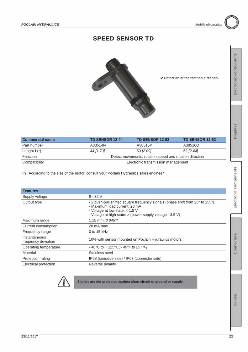
SPEED SENSOR TD
Commercial name TD SENSOR 12-44 TD SENSOR 12-53 TD SENSOR 12-62Part number A38514N A38515P A38516QLenght L(*) 44 [1.73] 53 [2.09] 62 [2.44]Function Detect movements: rotation speed and rotation directionCompatibility Electronic transmission management
(*) : According to the size of the motor, consult your Poclain Hydraulics sales engineer
FeaturesSupply voltage 8 - 32 VOutput type - 2 push-pull shifted square frequency signals (phase shift from 25° to 155°)
- Maximum load current: 20 mA- Voltage at low state: < 1.5 V- Voltage at high state: > (power supply voltage - 3.5 V)
Maximum range 1.15 mm [0.045’’]Current consumption 20 mA max.Frequency range 0 to 15 kHzInstantaneous frequency deviation 10% with sensor mounted on Poclain Hydraulics motors
Operating temperature - 40°C to + 125°C [- 40°F to 257°F]Material Stainless steelProtection rating IP68 (sensitive side) / IP67 (connector side)Electrical protection Reverse polarity
Signals are not protected against short circuit to ground or supply.
Detection of the rotation direction.
24 23/11/2017
Mobile electronics POCLAIN HYDRAULICS
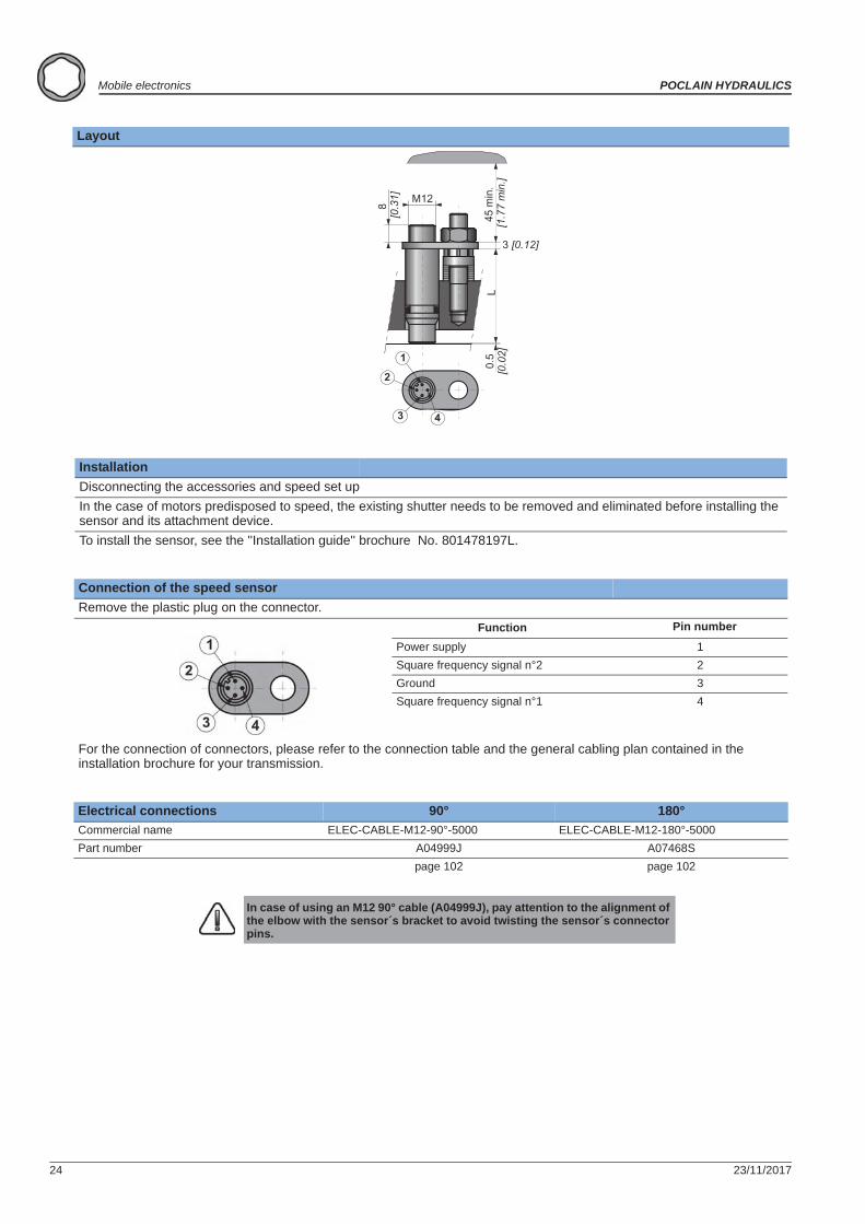
Layout
InstallationDisconnecting the accessories and speed set upIn the case of motors predisposed to speed, the existing shutter needs to be removed and eliminated before installing the sensor and its attachment device.To install the sensor, see the ''Installation guide'' brochure No. 801478197L.
Connection of the speed sensorRemove the plastic plug on the connector.
Function Pin number
Power supply 1Square frequency signal n°2 2Ground 3Square frequency signal n°1 4
For the connection of connectors, please refer to the connection table and the general cabling plan contained in the installation brochure for your transmission.
Electrical connections 90° 180°Commercial name ELEC-CABLE-M12-90°-5000 ELEC-CABLE-M12-180°-5000Part number A04999J A07468S
page 102 page 102
In case of using an M12 90° cable (A04999J), pay attention to the alignment of the elbow with the sensor´s bracket to avoid twisting the sensor´s connector pins.
23/11/2017 25
POCLAIN HYDRAULICS Mobile electronics
Elec
tron
ic c
ontr
ol u
nits
Elec
tron
ic c
ompo
nent
sC
onne
ctor
sC
able
sD
ispl
ays
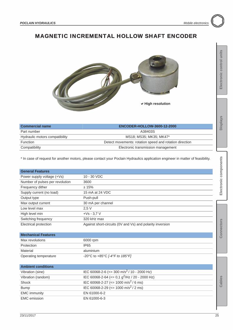
MAGNETIC INCREMENTAL HOLLOW SHAFT ENCODER
Commercial name ENCODER-HOLLOW-3600-12-2000Part number A38403SHydraulic motors compatibility MS18; MS35; MK35; MK47*Function Detect movements: rotation speed and rotation directionCompatibility Electronic transmission management
* In case of request for another motors, please contact your Poclain Hydraulics application engineer in matter of feasibility.
General FeaturesPower supply voltage (+Vs) 10 - 30 VDCNumber of pulses per revolution 3600Frequency dither ± 15%Supply current (no load) 15 mA at 24 VDCOutput type Push-pullMax output current 30 mA per channelLow level max 2,5 VHigh level min +Vs - 3,7 VSwitching frequency 320 kHz maxElectrical protection Against short-circuits (0V and Vs) and polarity inversion
Mechanical FeaturesMax revolutions 6000 rpmProtection IP65Material aluminiumOperating temperature -20°C to +85°C [-4°F to 185°F]
Ambient conditionsVibration (sine) IEC 60068-2-6 (<= 300 m/s2 / 10 - 2000 Hz)Vibration (random) IEC 60068-2-64 (<= 0,1 g2/Hz / 20 - 2000 Hz)Shock IEC 60068-2-27 (<= 1000 m/s2 / 6 ms)Bump IEC 60068-2-29 (<= 1000 m/s2 / 2 ms)EMC immunity EN 61000-6-2EMC emission EN 61000-6-3
High resolution
26 23/11/2017
Mobile electronics POCLAIN HYDRAULICS
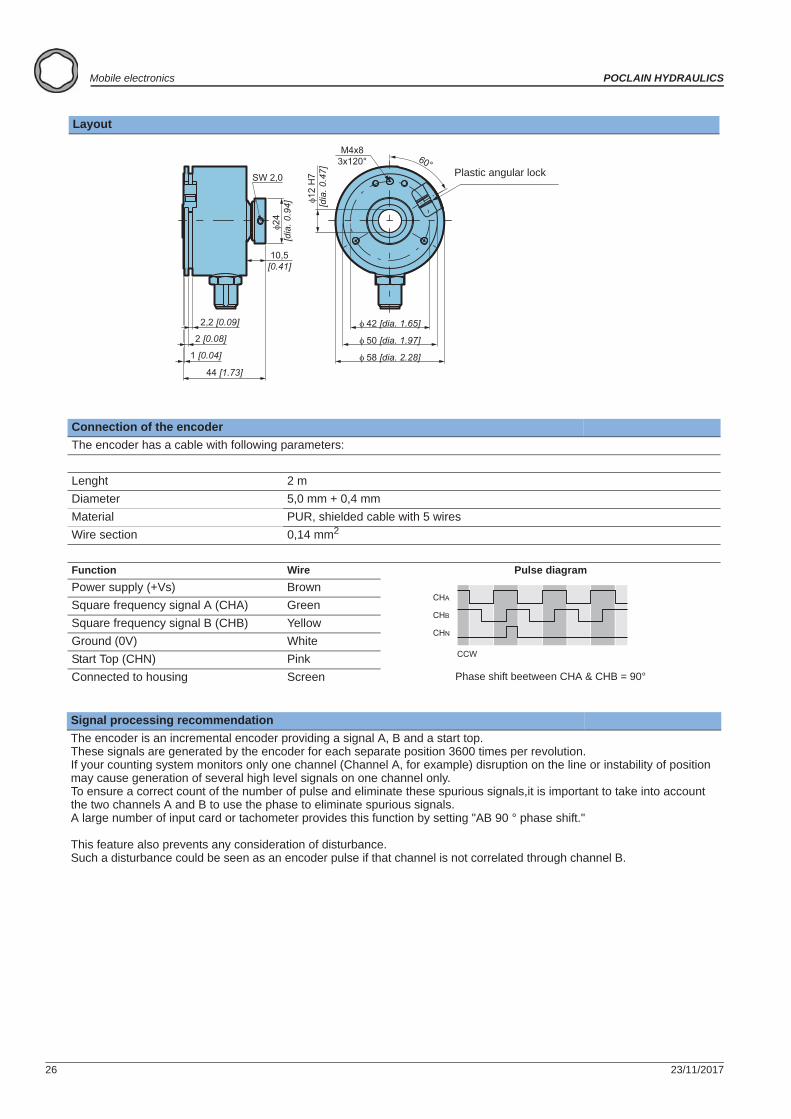
Layout
Connection of the encoderThe encoder has a cable with following parameters:
Lenght 2 mDiameter 5,0 mm + 0,4 mmMaterial PUR, shielded cable with 5 wiresWire section 0,14 mm2
Function Wire Pulse diagramPower supply (+Vs) BrownSquare frequency signal A (CHA) GreenSquare frequency signal B (CHB) YellowGround (0V) WhiteStart Top (CHN) PinkConnected to housing Screen Phase shift beetween CHA & CHB = 90°
Signal processing recommendationThe encoder is an incremental encoder providing a signal A, B and a start top.These signals are generated by the encoder for each separate position 3600 times per revolution.If your counting system monitors only one channel (Channel A, for example) disruption on the line or instability of position may cause generation of several high level signals on one channel only.To ensure a correct count of the number of pulse and eliminate these spurious signals,it is important to take into account the two channels A and B to use the phase to eliminate spurious signals.A large number of input card or tachometer provides this function by setting "AB 90 ° phase shift." This feature also prevents any consideration of disturbance.Such a disturbance could be seen as an encoder pulse if that channel is not correlated through channel B.
24
[dia
. 0.9
4]
10,5[0.41]
SW 2,0
2,2 [0.09]
2 [0.08]
1 [0.04]
44 [1.73]
M4x83x120°
12 H
7 [d
ia. 0
.47]
50 [dia. 1.97]
58 [dia. 2.28]
42 [dia. 1.65]
60°Plastic angular lock
CHA
CHB
CHN
CCW
23/11/2017 27
POCLAIN HYDRAULICS Mobile electronics
Elec
tron
ic c
ontr
ol u
nits
Elec
tron
ic c
ompo
nent
sC
onne
ctor
sC
able
sD
ispl
ays
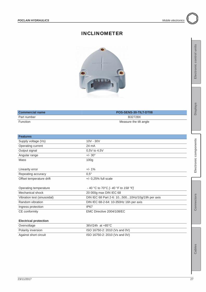
INCLINOMETER
Commercial name POS-SENS-30-TILT-DT08Part number B32728XFunction Measure the tilt angle
FeaturesSupply voltage (Vs) 10V - 30VOperating current 24 mAOutput signal 0,5V to 4,5VAngular range +/- 30°Mass 100g
Linearity error +/- 1%Repeating accuracy 0,5°Offset temperature drift +/- 0,25% full scale
Operating temperature - 40 °C to 70°C [- 40 °F to 158 °F]Mechanical shock 20 000g max DIN IEC 68Vibration test (sinusoidal) DIN IEC 68 Part 2-6: 10...500...10Hz/10g/19h per axisRandom vibration DIN IEC 68-2-64: 10-350Hz 16h per axisIngress protection IP67CE conformity EMC Directive 2004/108/EC
Electrical protectionOvervoltage 36V/24h at +85°CPolarity inversion ISO 16750-2: 2010 (Vs and 0V)Against short circuit ISO 16750-2: 2010 (Vs and 0V)
28 23/11/2017
Mobile electronics POCLAIN HYDRAULICS
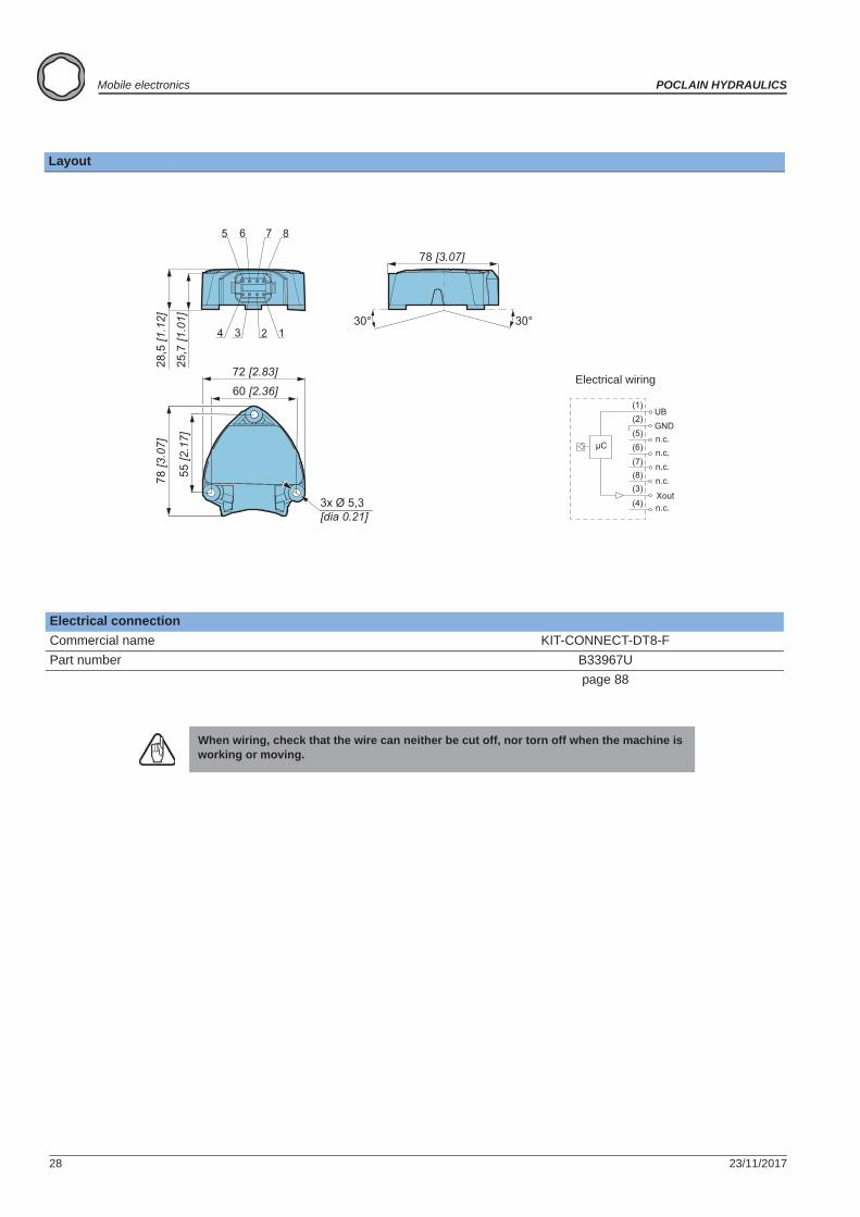
Layout
Electrical connectionCommercial name KIT-CONNECT-DT8-FPart number B33967U
page 88
When wiring, check that the wire can neither be cut off, nor torn off when the machine is working or moving.
72 [2.83]
60 [2.36]
55 [2
.17]
78 [3
.07]
3x Ø 5,3 [dia 0.21]
78 [3.07]
25
,7 [1
.01]
28
,5 [1
.12]
4 3 2 1
5 6 7 8
30°30°
UBGND
Xout
(1)(2)(5)(6)
(7)(8)(3)
(4)
n.c.n.c.n.c.n.c.
n.c.
Electrical wiring
23/11/2017 29
POCLAIN HYDRAULICS Mobile electronics
Elec
tron
ic c
ontr
ol u
nits
Elec
tron
ic c
ompo
nent
sC
onne
ctor
sC
able
sD
ispl
ays
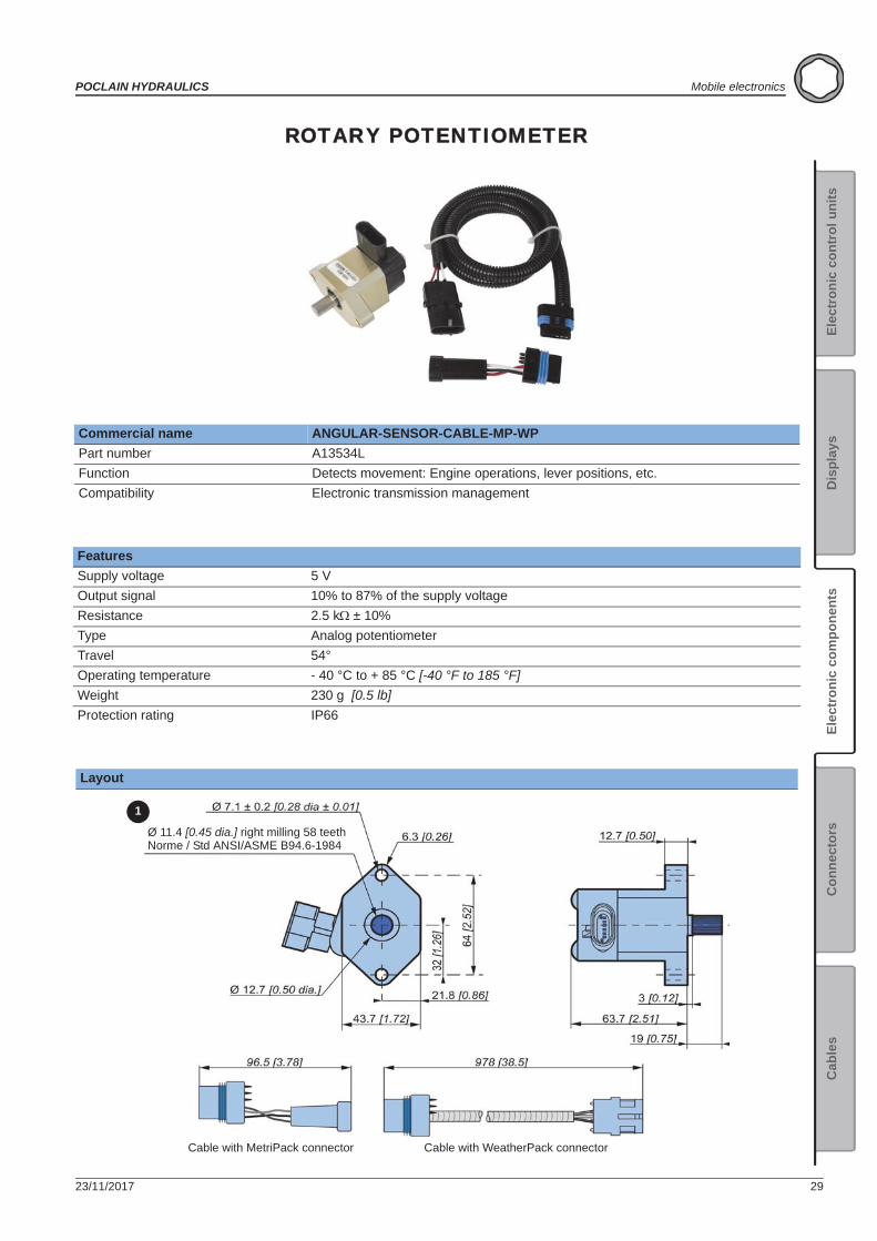
ROTARY POTENTIOMETER
Commercial name ANGULAR-SENSOR-CABLE-MP-WPPart number A13534LFunction Detects movement: Engine operations, lever positions, etc.Compatibility Electronic transmission management
FeaturesSupply voltage 5 VOutput signal 10% to 87% of the supply voltageResistance 2.5 k ± 10%Type Analog potentiometerTravel 54°Operating temperature - 40 °C to + 85 °C [-40 °F to 185 °F]Weight 230 g [0.5 lb]Protection rating IP66
Layout
1
Ø 11.4 [0.45 dia.] right milling 58 teethNorme / Std ANSI/ASME B94.6-1984
Cable with MetriPack connector Cable with WeatherPack connector
30 23/11/2017
Mobile electronics POCLAIN HYDRAULICS
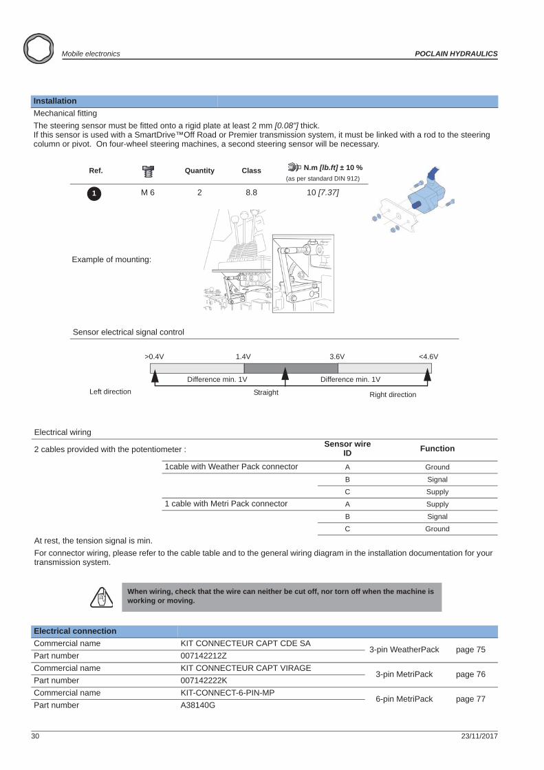
InstallationMechanical fittingThe steering sensor must be fitted onto a rigid plate at least 2 mm [0.08"] thick.If this sensor is used with a SmartDrive™Off Road or Premier transmission system, it must be linked with a rod to the steering column or pivot. On four-wheel steering machines, a second steering sensor will be necessary.
Ref. Quantity Class N.m [lb.ft] ± 10 %(as per standard DIN 912)
M 6 2 8.8 10 [7.37]
Example of mounting:
Sensor electrical signal control
Electrical wiring
2 cables provided with the potentiometer : Sensor wire ID Function
1cable with Weather Pack connector A Ground
B Signal
C Supply1 cable with Metri Pack connector A Supply
B Signal
C GroundAt rest, the tension signal is min.For connector wiring, please refer to the cable table and to the general wiring diagram in the installation documentation for your transmission system.
When wiring, check that the wire can neither be cut off, nor torn off when the machine is working or moving.
Electrical connectionCommercial name KIT CONNECTEUR CAPT CDE SA
3-pin WeatherPack page 75Part number 007142212ZCommercial name KIT CONNECTEUR CAPT VIRAGE
3-pin MetriPack page 76Part number 007142222KCommercial name KIT-CONNECT-6-PIN-MP
6-pin MetriPack page 77Part number A38140G
1
Difference min. 1V
Left direction Straight Right direction
Difference min. 1V
>0.4V <4.6V3.6V1.4V

23/11/2017 31
POCLAIN HYDRAULICS Mobile electronics
Elec
tron
ic c
ontr
ol u
nits
Elec
tron
ic c
ompo
nent
sC
onne
ctor
sC
able
sD
ispl
ays
20 BAR PRESSURE SENSOR
Commercial name PRES-SENSOR-20B-OT1-G1/4Part number A21362UFunction Measure the case pressureCompatibility Electronic transmission management
FeaturesSupply voltage (Vs) 5 V ± 0.5 VOutput signal 0.5V to 4.5V ratiometricPressure range 20 bars [290 PSI]Over pressure safety 50 bars [725 PSI]Pressure connection G1/4"Response time 2 msAccuracy 1% FSUsing temperature range Medium - 40 °C to 125 °C [- 40 °F to 257 °F]
Ambient - 40 °C to 100 °C [- 40 °F to 212 °F]Storage - 40 °C to 120 °C [- 40 °F to 248 °F]
Ingress protection IP67Electrical protection Overvoltage: 28V
Polarity inversion: -28VAgainst short circuits (0V and Vs)
CE conformity EN 61326Shock resistance 500 g according to DIN EN 837Vibration resistance 20 g according to IEC 68-2
20 bar
4,5 V
0,5 V

32 23/11/2017
Mobile electronics POCLAIN HYDRAULICS
Layout G1/4 sensor
InstallationFor transmissions controlled by SmartDrive™ Easy Plus, Master and Premier System electronic control systems, the sensor is fitted on the case motor pressure circuit.
For other applications, please consult your Poclain Hydraulics applications engineer.
Hydraulic connectionNut Seal N.m [lb.ft] ± 10 %
G 1/4" FPM 30 [22]
Observe the torques indicated.
Electrical connection Commercial name Part numberCable for pressure sensor connection CABLE-PRESSURE-SENSOR-3M 003141105U page 101
When wiring, check that the wire can neither be cut off, nor torn off when the machine is working or moving.
A: GroundB: 5 VccC: Signal 0.5 to 4.5 V
Connector side viewSensor side view
23/11/2017 33
POCLAIN HYDRAULICS Mobile electronics
Elec
tron
ic c
ontr
ol u
nits
Elec
tron
ic c
ompo
nent
sC
onne
ctor
sC
able
sD
ispl
ays
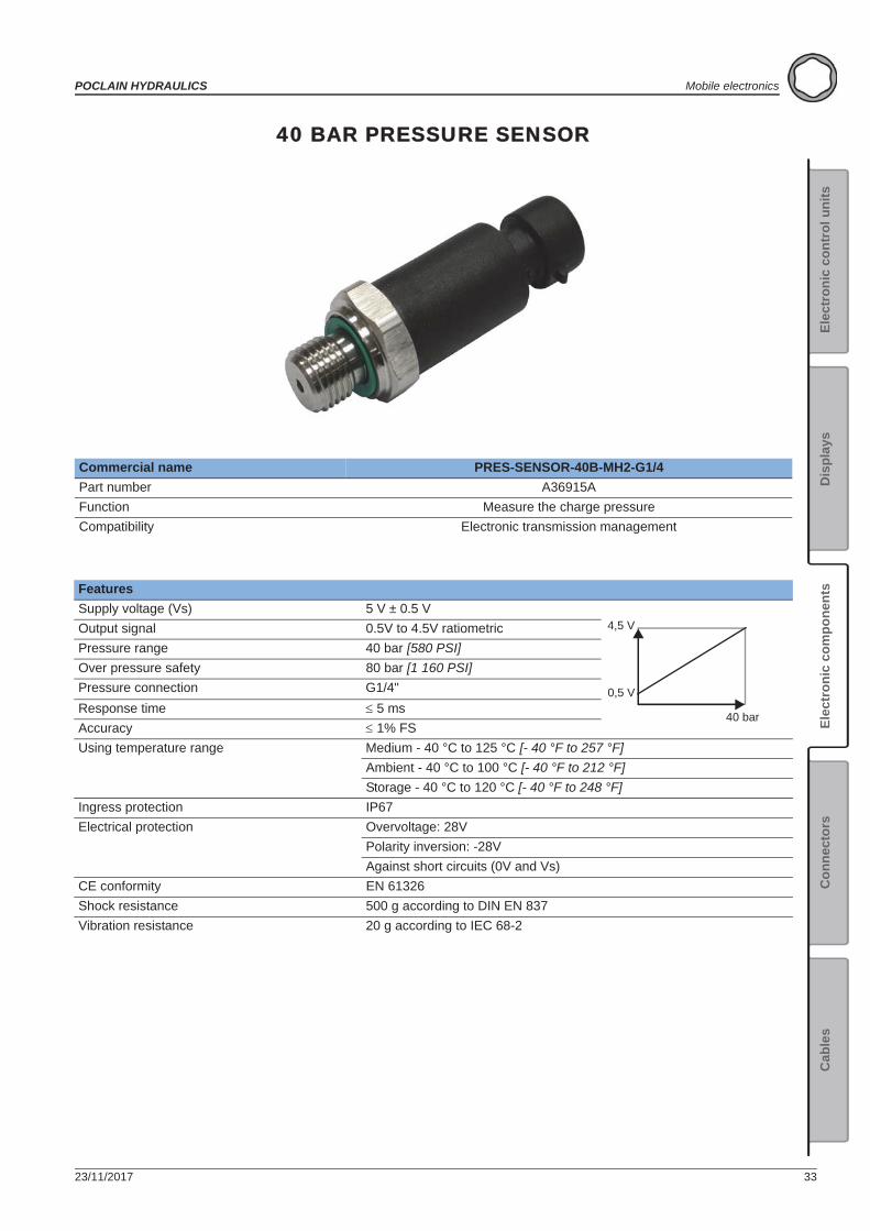
40 BAR PRESSURE SENSOR
Commercial name PRES-SENSOR-40B-MH2-G1/4Part number A36915AFunction Measure the charge pressureCompatibility Electronic transmission management
FeaturesSupply voltage (Vs) 5 V ± 0.5 VOutput signal 0.5V to 4.5V ratiometricPressure range 40 bar [580 PSI]Over pressure safety 80 bar [1 160 PSI]Pressure connection G1/4"Response time 5 msAccuracy 1% FSUsing temperature range Medium - 40 °C to 125 °C [- 40 °F to 257 °F]
Ambient - 40 °C to 100 °C [- 40 °F to 212 °F]Storage - 40 °C to 120 °C [- 40 °F to 248 °F]
Ingress protection IP67Electrical protection Overvoltage: 28V
Polarity inversion: -28VAgainst short circuits (0V and Vs)
CE conformity EN 61326Shock resistance 500 g according to DIN EN 837Vibration resistance 20 g according to IEC 68-2
40 bar
4,5 V
0,5 V
34 23/11/2017
Mobile electronics POCLAIN HYDRAULICS
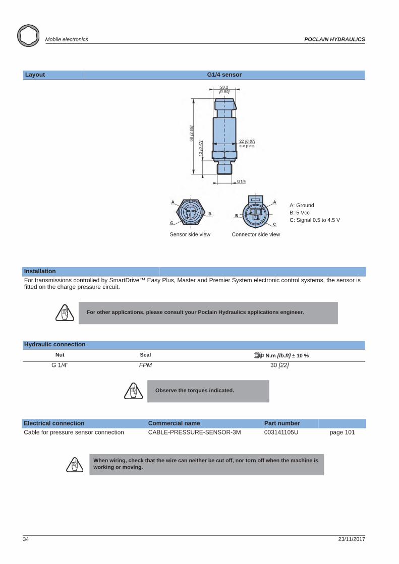
Layout G1/4 sensor
InstallationFor transmissions controlled by SmartDrive™ Easy Plus, Master and Premier System electronic control systems, the sensor is fitted on the charge pressure circuit.
For other applications, please consult your Poclain Hydraulics applications engineer.
Hydraulic connectionNut Seal N.m [lb.ft] ± 10 %
G 1/4" FPM 30 [22]
Observe the torques indicated.
Electrical connection Commercial name Part numberCable for pressure sensor connection CABLE-PRESSURE-SENSOR-3M 003141105U page 101
When wiring, check that the wire can neither be cut off, nor torn off when the machine is working or moving.
A: GroundB: 5 VccC: Signal 0.5 to 4.5 V
Connector side viewSensor side view
23/11/2017 35
POCLAIN HYDRAULICS Mobile electronics
Elec
tron
ic c
ontr
ol u
nits
Elec
tron
ic c
ompo
nent
sC
onne
ctor
sC
able
sD
ispl
ays
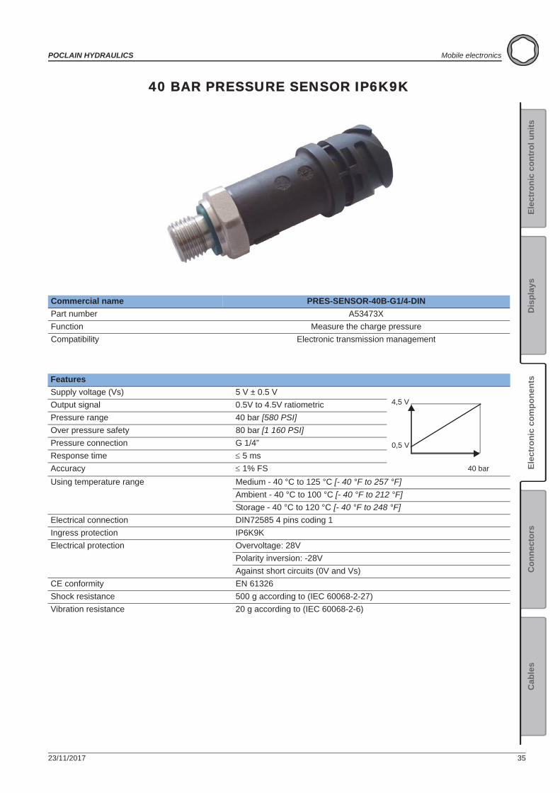
40 BAR PRESSURE SENSOR IP6K9K
Commercial name PRES-SENSOR-40B-G1/4-DINPart number A53473XFunction Measure the charge pressureCompatibility Electronic transmission management
FeaturesSupply voltage (Vs) 5 V ± 0.5 VOutput signal 0.5V to 4.5V ratiometricPressure range 40 bar [580 PSI]Over pressure safety 80 bar [1 160 PSI]Pressure connection G 1/4”Response time 5 msAccuracy 1% FSUsing temperature range Medium - 40 °C to 125 °C [- 40 °F to 257 °F]
Ambient - 40 °C to 100 °C [- 40 °F to 212 °F]Storage - 40 °C to 120 °C [- 40 °F to 248 °F]
Electrical connection DIN72585 4 pins coding 1Ingress protection IP6K9KElectrical protection Overvoltage: 28V
Polarity inversion: -28VAgainst short circuits (0V and Vs)
CE conformity EN 61326Shock resistance 500 g according to (IEC 60068-2-27)Vibration resistance 20 g according to (IEC 60068-2-6)
40 bar
4,5 V
0,5 V
36 23/11/2017
Mobile electronics POCLAIN HYDRAULICS
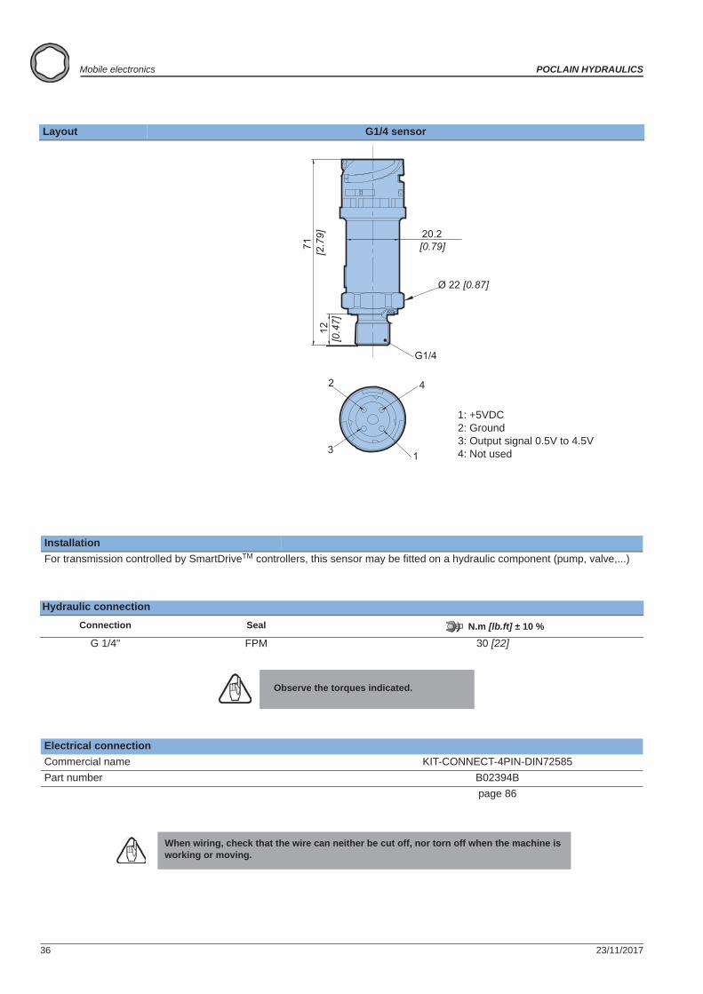
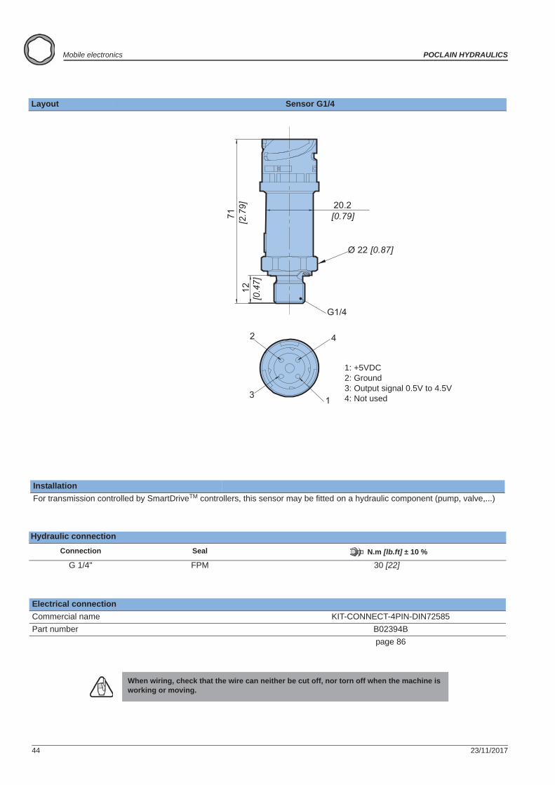
Layout G1/4 sensor
InstallationFor transmission controlled by SmartDriveTM controllers, this sensor may be fitted on a hydraulic component (pump, valve,...)
Hydraulic connectionConnection Seal N.m [lb.ft] ± 10 %
G 1/4" FPM 30 [22]
Observe the torques indicated.
Electrical connectionCommercial name KIT-CONNECT-4PIN-DIN72585Part number B02394B
page 86
When wiring, check that the wire can neither be cut off, nor torn off when the machine is working or moving.
G1/4
1
2
3
4
Ø 22 [0.87]
20.2[0.79][2
.79]
7112
[0.4
7]
1: +5VDC2: Ground3: Output signal 0.5V to 4.5V 4: Not used
23/11/2017 37
POCLAIN HYDRAULICS Mobile electronics
Elec
tron
ic c
ontr
ol u
nits
Elec
tron
ic c
ompo
nent
sC
onne
ctor
sC
able
sD
ispl
ays
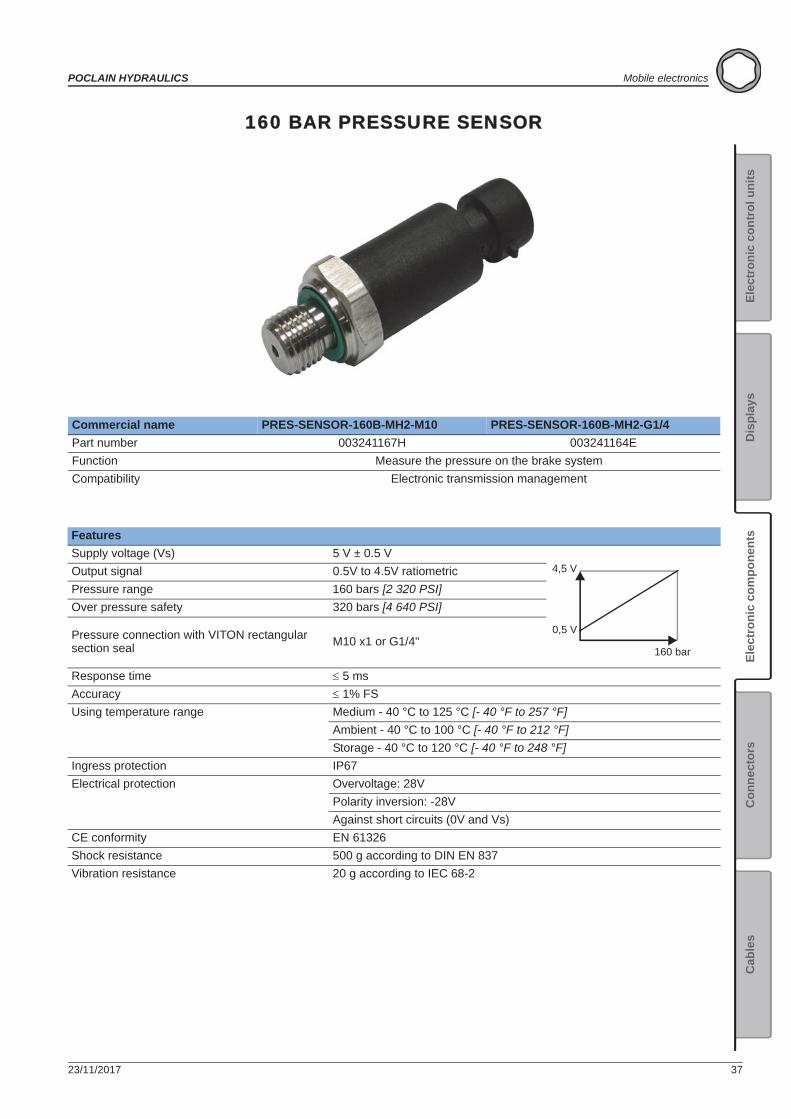
160 BAR PRESSURE SENSOR
Commercial name PRES-SENSOR-160B-MH2-M10 PRES-SENSOR-160B-MH2-G1/4Part number 003241167H 003241164EFunction Measure the pressure on the brake systemCompatibility Electronic transmission management
FeaturesSupply voltage (Vs) 5 V ± 0.5 VOutput signal 0.5V to 4.5V ratiometricPressure range 160 bars [2 320 PSI]Over pressure safety 320 bars [4 640 PSI]
Pressure connection with VITON rectangular section seal M10 x1 or G1/4"
Response time 5 msAccuracy 1% FSUsing temperature range Medium - 40 °C to 125 °C [- 40 °F to 257 °F]
Ambient - 40 °C to 100 °C [- 40 °F to 212 °F]Storage - 40 °C to 120 °C [- 40 °F to 248 °F]
Ingress protection IP67Electrical protection Overvoltage: 28V
Polarity inversion: -28VAgainst short circuits (0V and Vs)
CE conformity EN 61326Shock resistance 500 g according to DIN EN 837Vibration resistance 20 g according to IEC 68-2
160 bar
4,5 V
0,5 V
38 23/11/2017
Mobile electronics POCLAIN HYDRAULICS
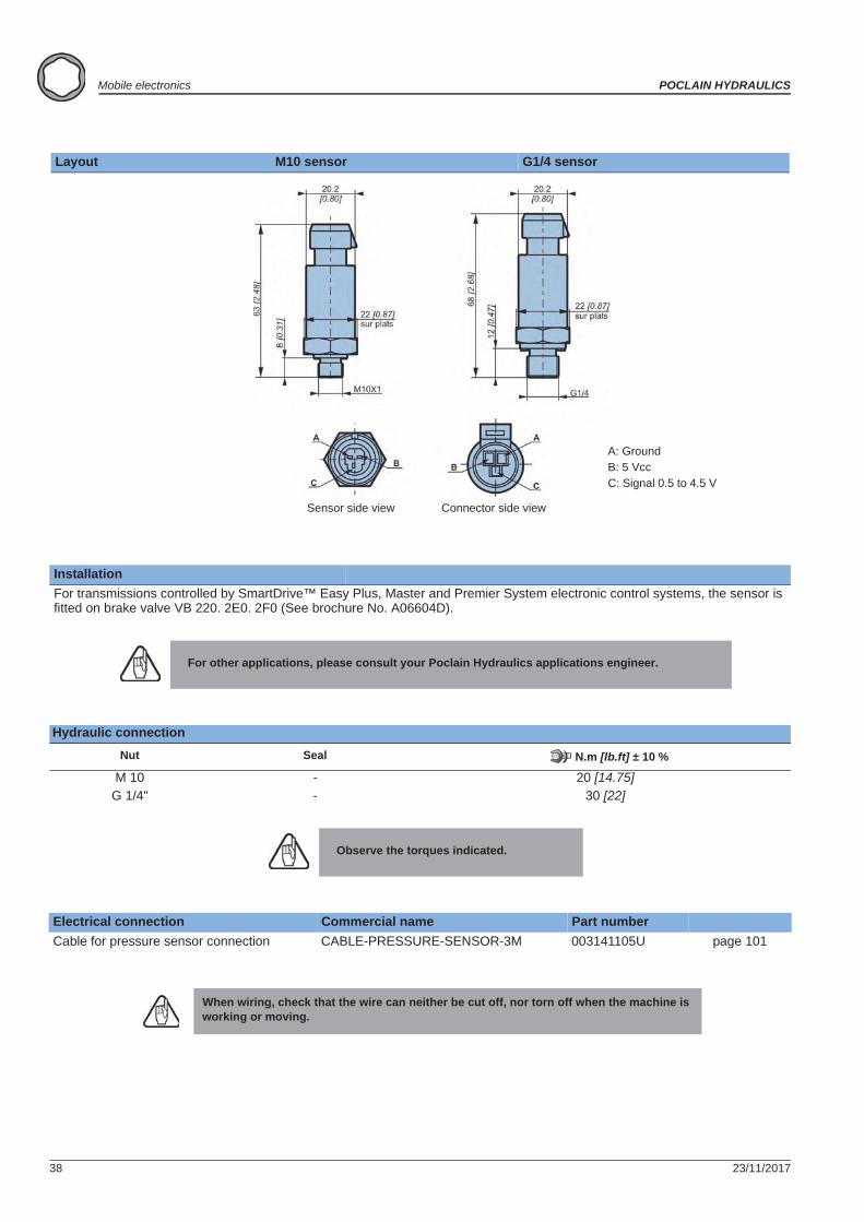
Layout M10 sensor G1/4 sensor
InstallationFor transmissions controlled by SmartDrive™ Easy Plus, Master and Premier System electronic control systems, the sensor is fitted on brake valve VB 220. 2E0. 2F0 (See brochure No. A06604D).
For other applications, please consult your Poclain Hydraulics applications engineer.
Hydraulic connectionNut Seal N.m [lb.ft] ± 10 %
M 10 - 20 [14.75]G 1/4" - 30 [22]
Observe the torques indicated.
Electrical connection Commercial name Part numberCable for pressure sensor connection CABLE-PRESSURE-SENSOR-3M 003141105U page 101
When wiring, check that the wire can neither be cut off, nor torn off when the machine is working or moving.
Sensor side view Connector side view
A: GroundB: 5 VccC: Signal 0.5 to 4.5 V
23/11/2017 39
POCLAIN HYDRAULICS Mobile electronics
Elec
tron
ic c
ontr
ol u
nits
Elec
tron
ic c
ompo
nent
sC
onne
ctor
sC
able
sD
ispl
ays
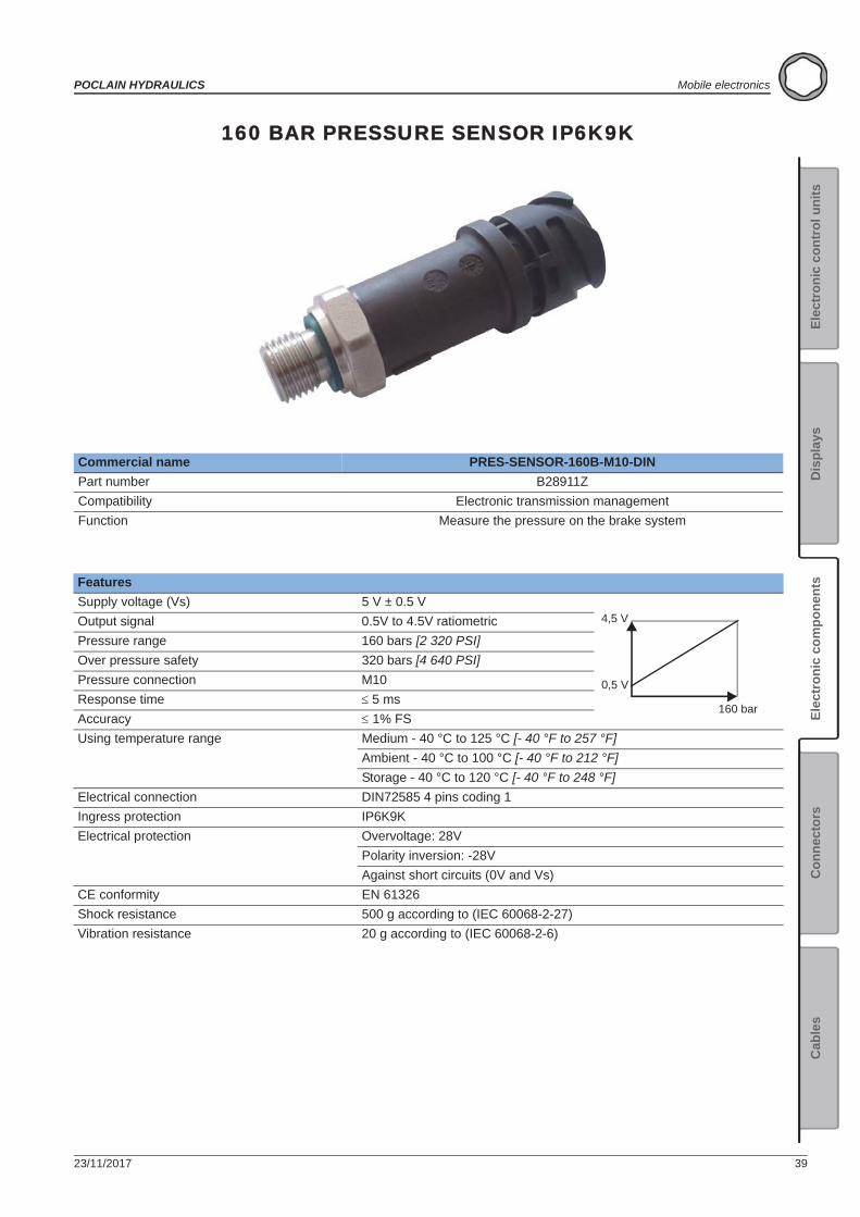
160 BAR PRESSURE SENSOR IP6K9K
Commercial name PRES-SENSOR-160B-M10-DINPart number B28911ZCompatibility Electronic transmission managementFunction Measure the pressure on the brake system
FeaturesSupply voltage (Vs) 5 V ± 0.5 VOutput signal 0.5V to 4.5V ratiometricPressure range 160 bars [2 320 PSI]Over pressure safety 320 bars [4 640 PSI]Pressure connection M10Response time 5 msAccuracy 1% FSUsing temperature range Medium - 40 °C to 125 °C [- 40 °F to 257 °F]
Ambient - 40 °C to 100 °C [- 40 °F to 212 °F]Storage - 40 °C to 120 °C [- 40 °F to 248 °F]
Electrical connection DIN72585 4 pins coding 1Ingress protection IP6K9KElectrical protection Overvoltage: 28V
Polarity inversion: -28VAgainst short circuits (0V and Vs)
CE conformity EN 61326Shock resistance 500 g according to (IEC 60068-2-27)Vibration resistance 20 g according to (IEC 60068-2-6)
160 bar
4,5 V
0,5 V
40 23/11/2017
Mobile electronics POCLAIN HYDRAULICS
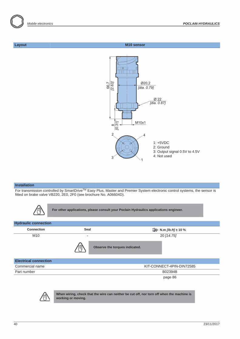
Layout M10 sensor
InstallationFor transmission controlled by SmartDriveTM Easy Plus, Master and Premier System electronic control systems, the sensor is fitted on brake valve VB220, 2E0, 2F0 (see brochure No. A06604D).
For other applications, please consult your Poclain Hydraulics applications engineer.
Hydraulic connectionConnection Seal N.m [lb.ft] ± 10 %
M10 - 20 [14.75]
Observe the torques indicated.
Electrical connectionCommercial name KIT-CONNECT-4PIN-DIN72585Part number B02394B
page 86
When wiring, check that the wire can neither be cut off, nor torn off when the machine is working or moving.
1
2
3
4
Ø 22
Ø20,2[dia. 0.79][2
.63]
66,7
8[0
.31]
[dia. 0.87]
M10x1
1: +5VDC2: Ground3: Output signal 0.5V to 4.5V 4: Not used
23/11/2017 41
POCLAIN HYDRAULICS Mobile electronics
Elec
tron
ic c
ontr
ol u
nits
Elec
tron
ic c
ompo
nent
sC
onne
ctor
sC
able
sD
ispl
ays
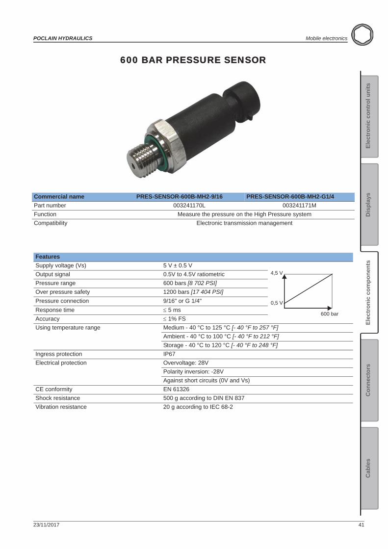
600 BAR PRESSURE SENSOR
Commercial name PRES-SENSOR-600B-MH2-9/16 PRES-SENSOR-600B-MH2-G1/4Part number 003241170L 003241171MFunction Measure the pressure on the High Pressure systemCompatibility Electronic transmission management
FeaturesSupply voltage (Vs) 5 V ± 0.5 VOutput signal 0.5V to 4.5V ratiometricPressure range 600 bars [8 702 PSI]Over pressure safety 1200 bars [17 404 PSI]Pressure connection 9/16" or G 1/4"Response time 5 msAccuracy 1% FSUsing temperature range Medium - 40 °C to 125 °C [- 40 °F to 257 °F]
Ambient - 40 °C to 100 °C [- 40 °F to 212 °F]Storage - 40 °C to 120 °C [- 40 °F to 248 °F]
Ingress protection IP67Electrical protection Overvoltage: 28V
Polarity inversion: -28VAgainst short circuits (0V and Vs)
CE conformity EN 61326Shock resistance 500 g according to DIN EN 837Vibration resistance 20 g according to IEC 68-2
600 bar
4,5 V
0,5 V
42 23/11/2017
Mobile electronics POCLAIN HYDRAULICS
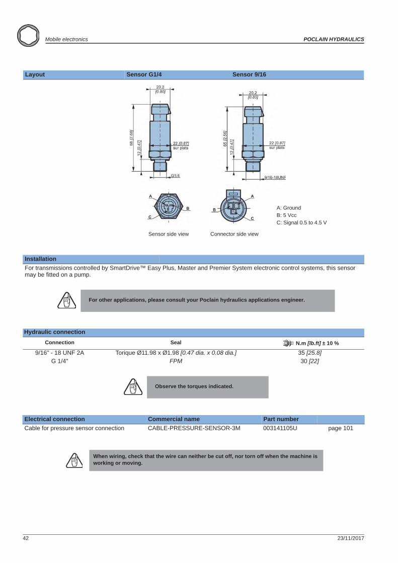
Layout Sensor G1/4 Sensor 9/16
InstallationFor transmissions controlled by SmartDrive™ Easy Plus, Master and Premier System electronic control systems, this sensor may be fitted on a pump.
For other applications, please consult your Poclain hydraulics applications engineer.
Hydraulic connectionConnection Seal N.m [lb.ft] ± 10 %
9/16" - 18 UNF 2A Torique Ø11.98 x Ø1.98 [0.47 dia. x 0.08 dia.] 35 [25.8]G 1/4" FPM 30 [22]
Observe the torques indicated.
Electrical connection Commercial name Part numberCable for pressure sensor connection CABLE-PRESSURE-SENSOR-3M 003141105U page 101
When wiring, check that the wire can neither be cut off, nor torn off when the machine is working or moving.
Sensor side view Connector side view
A: GroundB: 5 VccC: Signal 0.5 to 4.5 V
23/11/2017 43
POCLAIN HYDRAULICS Mobile electronics
Elec
tron
ic c
ontr
ol u
nits
Elec
tron
ic c
ompo
nent
sC
onne
ctor
sC
able
sD
ispl
ays
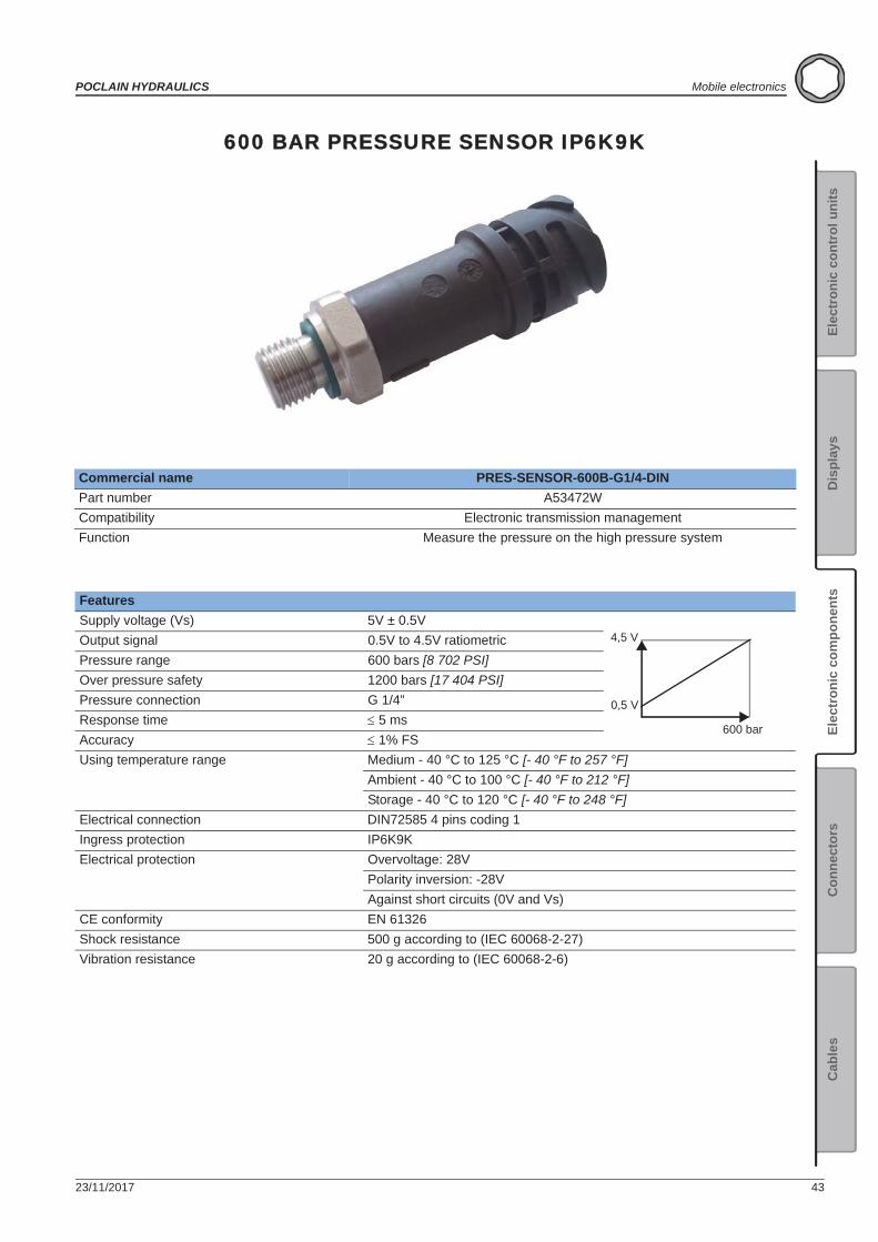
600 BAR PRESSURE SENSOR IP6K9K
Commercial name PRES-SENSOR-600B-G1/4-DINPart number A53472WCompatibility Electronic transmission managementFunction Measure the pressure on the high pressure system
FeaturesSupply voltage (Vs) 5V ± 0.5VOutput signal 0.5V to 4.5V ratiometricPressure range 600 bars [8 702 PSI]Over pressure safety 1200 bars [17 404 PSI]Pressure connection G 1/4”Response time 5 msAccuracy 1% FSUsing temperature range Medium - 40 °C to 125 °C [- 40 °F to 257 °F]
Ambient - 40 °C to 100 °C [- 40 °F to 212 °F]Storage - 40 °C to 120 °C [- 40 °F to 248 °F]
Electrical connection DIN72585 4 pins coding 1Ingress protection IP6K9KElectrical protection Overvoltage: 28V
Polarity inversion: -28VAgainst short circuits (0V and Vs)
CE conformity EN 61326Shock resistance 500 g according to (IEC 60068-2-27)Vibration resistance 20 g according to (IEC 60068-2-6)
4,5 V
0,5 V
600 bar
44 23/11/2017
Mobile electronics POCLAIN HYDRAULICS
Layout Sensor G1/4
InstallationFor transmission controlled by SmartDriveTM controllers, this sensor may be fitted on a hydraulic component (pump, valve,...)
Hydraulic connectionConnection Seal N.m [lb.ft] ± 10 %
G 1/4" FPM 30 [22]
Electrical connectionCommercial name KIT-CONNECT-4PIN-DIN72585Part number B02394B
page 86
When wiring, check that the wire can neither be cut off, nor torn off when the machine is working or moving.
G1/4
1
2
3
4
Ø 22 [0.87]
20.2[0.79][2
.79]
7112
[0.4
7]
1: +5VDC2: Ground3: Output signal 0.5V to 4.5V 4: Not used
23/11/2017 45
POCLAIN HYDRAULICS Mobile electronics
Elec
tron
ic c
ontr
ol u
nits
Elec
tron
ic c
ompo
nent
sC
onne
ctor
sC
able
sD
ispl
ays
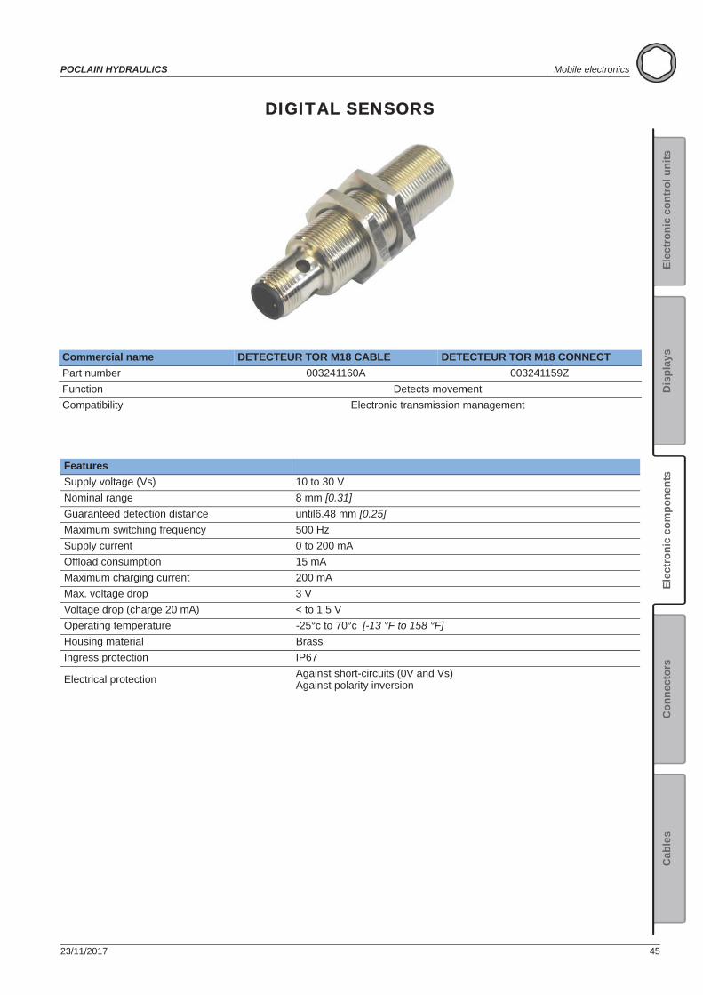
DIGITAL SENSORS
Commercial name DETECTEUR TOR M18 CABLE DETECTEUR TOR M18 CONNECTPart number 003241160A 003241159ZFunction Detects movementCompatibility Electronic transmission management
FeaturesSupply voltage (Vs) 10 to 30 V Nominal range 8 mm [0.31]Guaranteed detection distance until6.48 mm [0.25]Maximum switching frequency 500 HzSupply current 0 to 200 mAOffload consumption 15 mAMaximum charging current 200 mAMax. voltage drop 3 V Voltage drop (charge 20 mA) < to 1.5 VOperating temperature -25°c to 70°c [-13 °F to 158 °F]Housing material BrassIngress protection IP67
Electrical protection Against short-circuits (0V and Vs)Against polarity inversion
46 23/11/2017
Mobile electronics POCLAIN HYDRAULICS
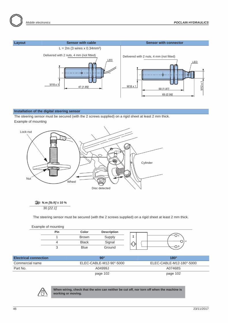
Layout Sensor with cable Sensor with connector
Installation of the digital steering sensorThe steering sensor must be secured (with the 2 screws supplied) on a rigid sheet at least 2 mm thick.Example of mounting
N.m [lb.ft] ± 10 %
30 [22.1]
The steering sensor must be secured (with the 2 screws supplied) on a rigid sheet at least 2 mm thick.
Example of mountingPin Color Description1 Brown Supply4 Black Signal3 Blue Ground
Electrical connection 90° 180°Commercial name ELEC-CABLE-M12-90°-5000 ELEC-CABLE-M12-180°-5000Part No. A04999J A07468S
page 102 page 102
When wiring, check that the wire can neither be cut off, nor torn off when the machine is working or moving.
Delivered with 2 nuts, 4 mm (not fitted) Delivered with 2 nuts, 4 mm (not fitted)
Lock-nut
NutWheel
Cylinder
Disc detected
L = 2m (3 wires x 0.34mm²)
23/11/2017 47
POCLAIN HYDRAULICS Mobile electronics
Elec
tron
ic c
ontr
ol u
nits
Elec
tron
ic c
ompo
nent
sC
onne
ctor
sC
able
sD
ispl
ays
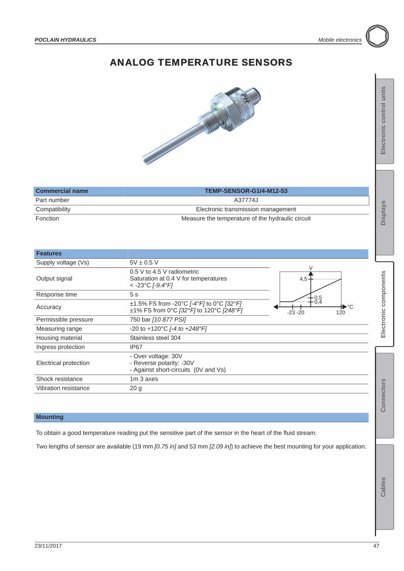
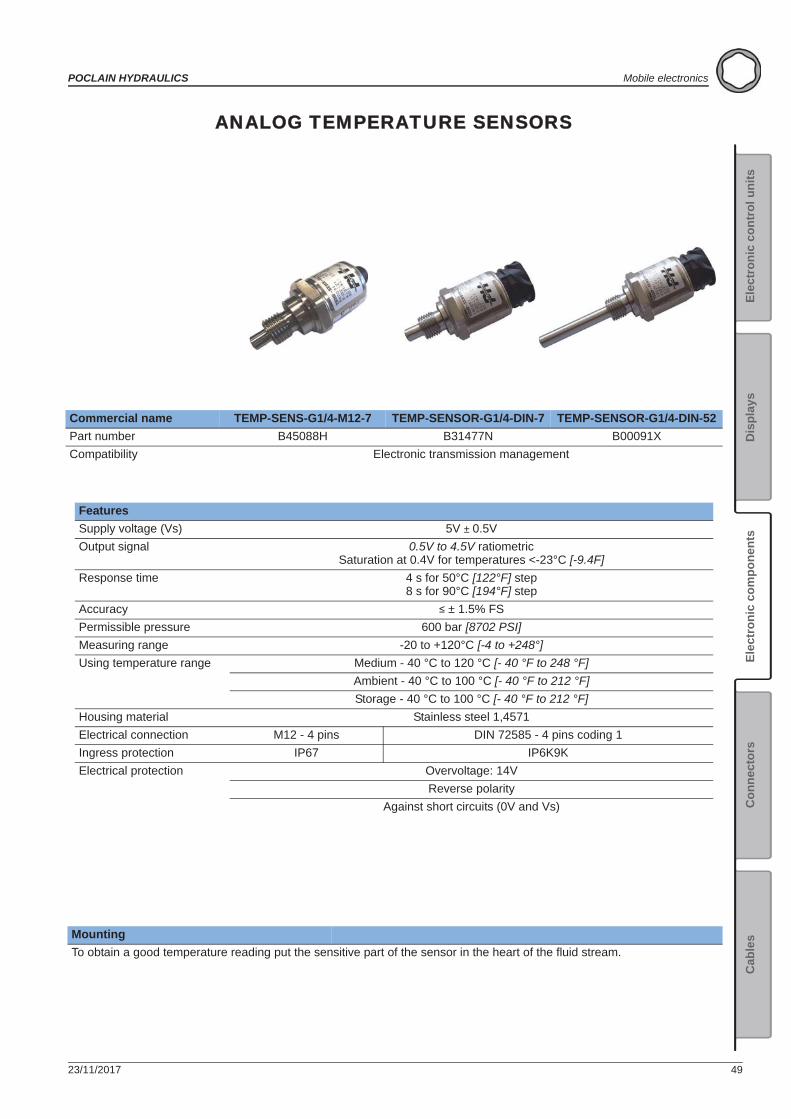
ANALOG TEMPERATURE SENSORS
Commercial name TEMP-SENSOR-G1/4-M12-53Part number A37774JCompatibility Electronic transmission managementFonction Measure the temperature of the hydraulic circuit
FeaturesSupply voltage (Vs) 5V ± 0.5 V
Output signal0.5 V to 4.5 V radiometricSaturation at 0.4 V for temperatures< -23°C [-9.4°F]
Response time 5 s
Accuracy ±1.5% FS from -20°C [-4°F] to 0°C [32°F]±1% FS from 0°C [32°F] to 120°C [248°F]
Permissible pressure 750 bar [10 877 PSI]Measuring range -20 to +120°C [-4 to +248°F]Housing material Stainless steel 304Ingress protection IP67
Electrical protection- Over voltage: 30V- Reverse polarity: -30V- Against short-circuits (0V and Vs)
Shock resistance 1m 3 axesVibration resistance 20 g
Mounting
To obtain a good temperature reading put the sensitive part of the sensor in the heart of the fluid stream.
Two lengths of sensor are available (19 mm [0.75 in] and 53 mm [2.09 in]) to achieve the best mounting for your application.
120-20
4,5
0,5
-23
0,4
V
°C
48 23/11/2017
Mobile electronics POCLAIN HYDRAULICS
Layout
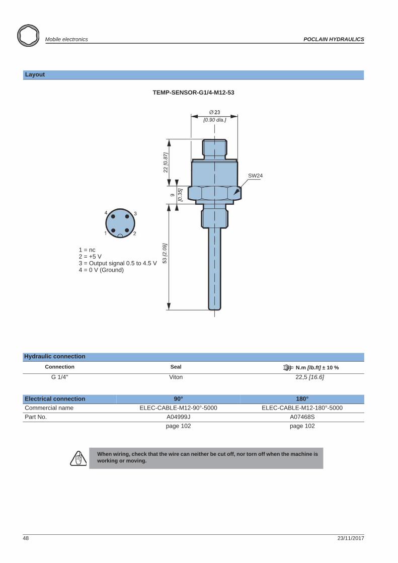
TEMP-SENSOR-G1/4-M12-53
Hydraulic connectionConnection Seal N.m [lb.ft] ± 10 %
G 1/4" Viton 22,5 [16.6]
Electrical connection 90° 180°Commercial name ELEC-CABLE-M12-90°-5000 ELEC-CABLE-M12-180°-5000Part No. A04999J A07468S
page 102 page 102
When wiring, check that the wire can neither be cut off, nor torn off when the machine is working or moving.
1 = nc2 = +5 V3 = Output signal 0.5 to 4.5 V4 = 0 V (Ground)
SW24
23/11/2017 49
POCLAIN HYDRAULICS Mobile electronics
Elec
tron
ic c
ontr
ol u
nits
Elec
tron
ic c
ompo
nent
sC
onne
ctor
sC
able
sD
ispl
ays
ANALOG TEMPERATURE SENSORS
Commercial name TEMP-SENS-G1/4-M12-7 TEMP-SENSOR-G1/4-DIN-7 TEMP-SENSOR-G1/4-DIN-52Part number B45088H B31477N B00091XCompatibility Electronic transmission management
FeaturesSupply voltage (Vs) 5V ± 0.5VOutput signal 0.5V to 4.5V ratiometric
Saturation at 0.4V for temperatures <-23°C [-9.4F]Response time 4 s for 50°C [122°F] step
8 s for 90°C [194°F] stepAccuracy ± 1.5% FSPermissible pressure 600 bar [8702 PSI]Measuring range -20 to +120°C [-4 to +248°]Using temperature range Medium - 40 °C to 120 °C [- 40 °F to 248 °F]
Ambient - 40 °C to 100 °C [- 40 °F to 212 °F]Storage - 40 °C to 100 °C [- 40 °F to 212 °F]
Housing material Stainless steel 1,4571Electrical connection M12 - 4 pins DIN 72585 - 4 pins coding 1Ingress protection IP67 IP6K9KElectrical protection Overvoltage: 14V
Reverse polarityAgainst short circuits (0V and Vs)
MountingTo obtain a good temperature reading put the sensitive part of the sensor in the heart of the fluid stream.
50 23/11/2017
Mobile electronics POCLAIN HYDRAULICS
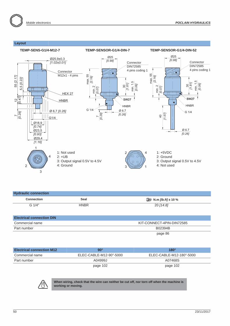
Layout
Hydraulic connectionConnection Seal N.m [lb.ft] ± 10 %
G 1/4" HNBR 20 [14.8]
Electrical connection DINCommercial name KIT-CONNECT-4PIN-DIN72585Part number B02394B
page 86
Electrical connection M12 90° 180°Commercial name ELEC-CABLE-M12-90°-5000 ELEC-CABLE-M12-180°-5000Part number A04999J A07468S
page 102 page 102
When wiring, check that the wire can neither be cut off, nor torn off when the machine is working or moving.
4
1
2
3
SW27
HNBR
SW27
G 1/4
[1.8
1]30
min
. 1.5
[0.0
6]
Ø 6.7[0.26]
min
. 2[0
.07]
[2.1
6]m
ax. 5
5
40[1
.57]
Ø25[0.98]
1
2
3
4
55 [2
.17]
5,5
[0.2
2]
7 [0
.28]
12
[0.4
7]
Ø18,9 [0.74] Ø23,5 [0.93] Ø29,4 [1.16]
Ø25,9±0,3 [1.02±0.01]
Ø 6,7 [0.26]
G1/4
HEX 27
HNBR SW27
HNBR
SW27
G 1/4
[1.8
1]30
min
. 1.5
[0.0
6]
Ø 6.7[0.26]
min
. 2[0
.07]
[2.1
6]m
ax. 5
5
7[0
.28]
Ø25[0.98]
1: +5VDC2: Ground3: Output signal 0.5V to 4.5V 4: Not used
TEMP-SENSOR-G1/4-DIN-52TEMP-SENSOR-G1/4-DIN-7TEMP-SENS-G1/4-M12-7
Connector M12x1 - 4 pins
Connector DIN725854 pins coding 1
Connector DIN725854 pins coding 1
1: Not used2: +UB3: Output signal 0.5V to 4.5V 4: Ground
23/11/2017 51
POCLAIN HYDRAULICS Mobile electronics
Elec
tron
ic c
ontr
ol u
nits
Elec
tron
ic c
ompo
nent
sC
onne
ctor
sC
able
sD
ispl
ays
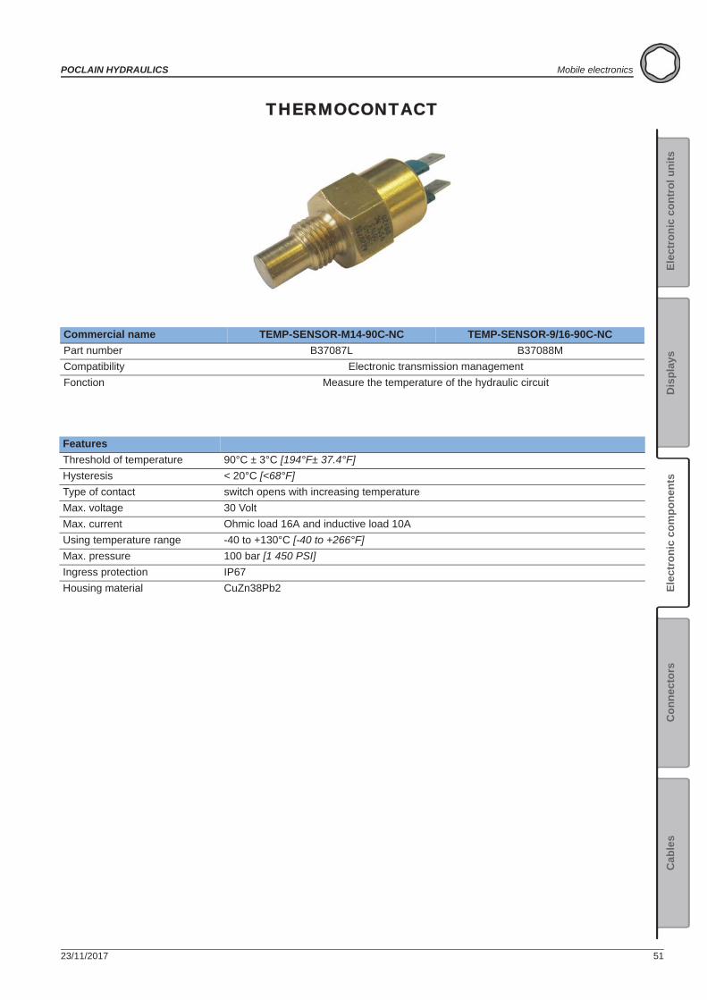
THERMOCONTACT
Commercial name TEMP-SENSOR-M14-90C-NC TEMP-SENSOR-9/16-90C-NCPart number B37087L B37088MCompatibility Electronic transmission managementFonction Measure the temperature of the hydraulic circuit
FeaturesThreshold of temperature 90°C ± 3°C [194°F± 37.4°F] Hysteresis < 20°C [<68°F]Type of contact switch opens with increasing temperatureMax. voltage 30 VoltMax. current Ohmic load 16A and inductive load 10AUsing temperature range -40 to +130°C [-40 to +266°F]Max. pressure 100 bar [1 450 PSI]Ingress protection IP67Housing material CuZn38Pb2
52 23/11/2017
Mobile electronics POCLAIN HYDRAULICS
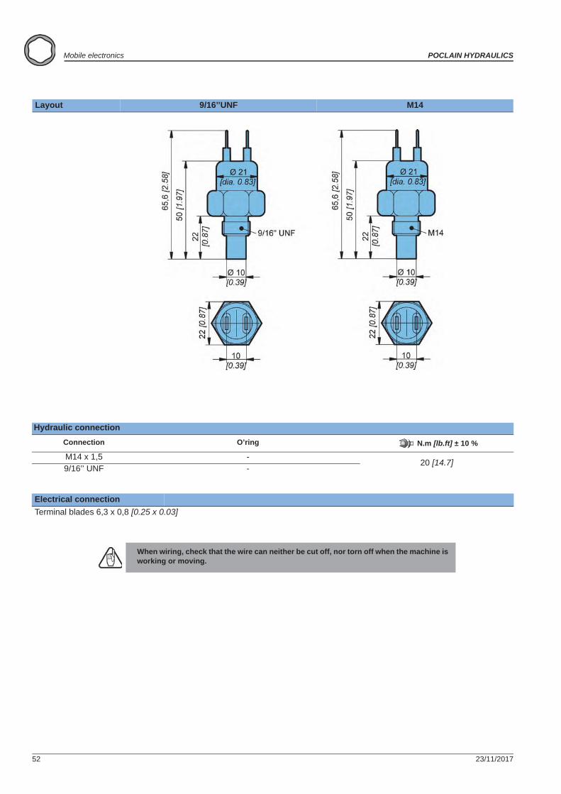
Layout 9/16’’UNF M14
Hydraulic connectionConnection O’ring N.m [lb.ft] ± 10 %
M14 x 1,5 -20 [14.7]
9/16’’ UNF -
Electrical connectionTerminal blades 6,3 x 0,8 [0.25 x 0.03]
When wiring, check that the wire can neither be cut off, nor torn off when the machine is working or moving.
23/11/2017 53
POCLAIN HYDRAULICS Mobile electronics
Elec
tron
ic c
ontr
ol u
nits
Elec
tron
ic c
ompo
nent
sC
onne
ctor
sC
able
sD
ispl
ays
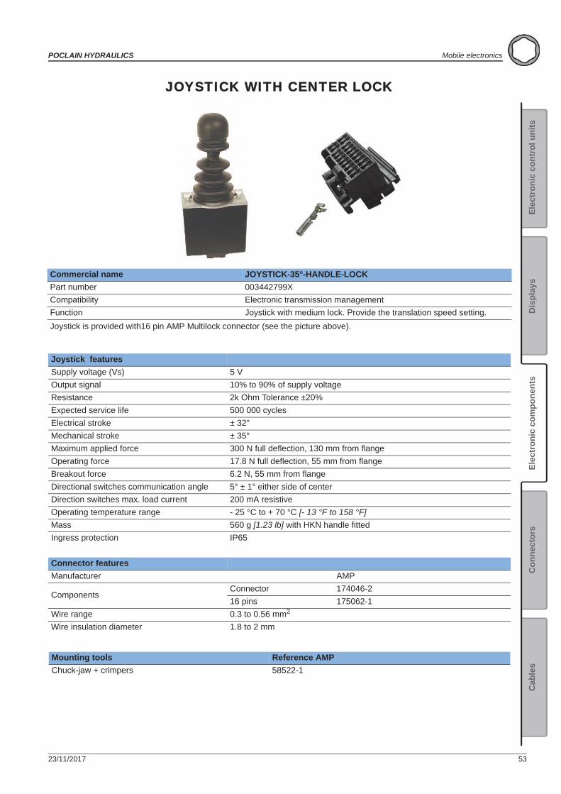
JOYSTICK WITH CENTER LOCK
Commercial name JOYSTICK-35°-HANDLE-LOCKPart number 003442799XCompatibility Electronic transmission managementFunction Joystick with medium lock. Provide the translation speed setting.Joystick is provided with16 pin AMP Multilock connector (see the picture above).
Joystick featuresSupply voltage (Vs) 5 VOutput signal 10% to 90% of supply voltageResistance 2k Ohm Tolerance ±20%Expected service life 500 000 cyclesElectrical stroke ± 32°Mechanical stroke ± 35°Maximum applied force 300 N full deflection, 130 mm from flangeOperating force 17.8 N full deflection, 55 mm from flangeBreakout force 6.2 N, 55 mm from flangeDirectional switches communication angle 5° ± 1° either side of centerDirection switches max. load current 200 mA resistiveOperating temperature range - 25 °C to + 70 °C [- 13 °F to 158 °F]Mass 560 g [1.23 lb] with HKN handle fittedIngress protection IP65
Connector featuresManufacturer AMP
ComponentsConnector 174046-216 pins 175062-1
Wire range 0.3 to 0.56 mm2
Wire insulation diameter 1.8 to 2 mm
Mounting tools Reference AMPChuck-jaw + crimpers 58522-1
54 23/11/2017
Mobile electronics POCLAIN HYDRAULICS
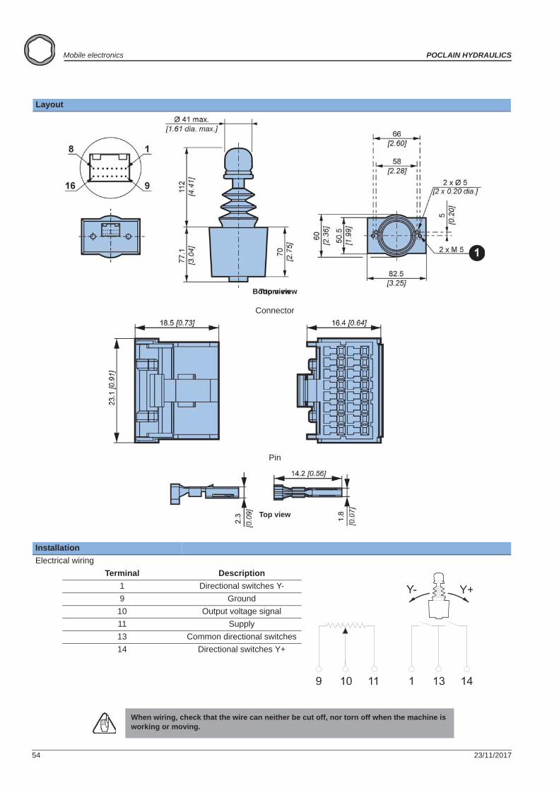
Layout
InstallationElectrical wiring
Terminal Description1 Directional switches Y-9 Ground
10 Output voltage signal11 Supply13 Common directional switches14 Directional switches Y+
When wiring, check that the wire can neither be cut off, nor torn off when the machine is working or moving.
Bottom viewTop view
Connector
Top view
Pin
23/11/2017 55
POCLAIN HYDRAULICS Mobile electronics
Elec
tron
ic c
ontr
ol u
nits
Elec
tron
ic c
ompo
nent
sC
onne
ctor
sC
able
sD
ispl
ays
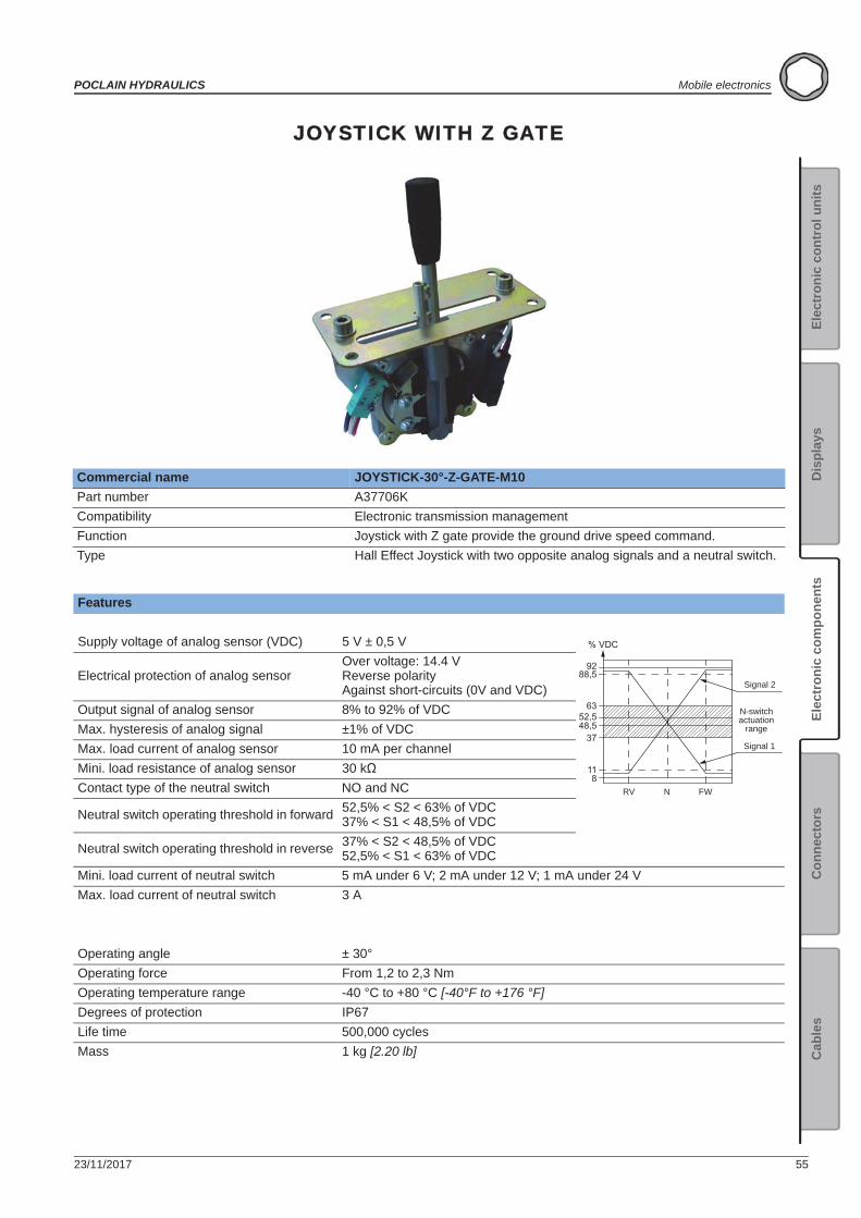
JOYSTICK WITH Z GATE
Commercial name JOYSTICK-30°-Z-GATE-M10Part number A37706KCompatibility Electronic transmission managementFunction Joystick with Z gate provide the ground drive speed command.Type Hall Effect Joystick with two opposite analog signals and a neutral switch.
Features
Supply voltage of analog sensor (VDC) 5 V ± 0,5 V
Electrical protection of analog sensorOver voltage: 14.4 VReverse polarityAgainst short-circuits (0V and VDC)
Output signal of analog sensor 8% to 92% of VDCMax. hysteresis of analog signal ±1% of VDCMax. load current of analog sensor 10 mA per channelMini. load resistance of analog sensor 30 kContact type of the neutral switch NO and NC
Neutral switch operating threshold in forward 52,5% < S2 < 63% of VDC37% < S1 < 48,5% of VDC
Neutral switch operating threshold in reverse 37% < S2 < 48,5% of VDC52,5% < S1 < 63% of VDC
Mini. load current of neutral switch 5 mA under 6 V; 2 mA under 12 V; 1 mA under 24 VMax. load current of neutral switch 3 A
Operating angle ± 30°Operating force From 1,2 to 2,3 NmOperating temperature range -40 °C to +80 °C [-40°F to +176 °F]Degrees of protection IP67Life time 500,000 cyclesMass 1 kg [2.20 lb]
% VDC
118
3748,552,5
63
88,592
Signal 2
Signal 1
RV N FW
N-switchactuation
range
56 23/11/2017
Mobile electronics POCLAIN HYDRAULICS
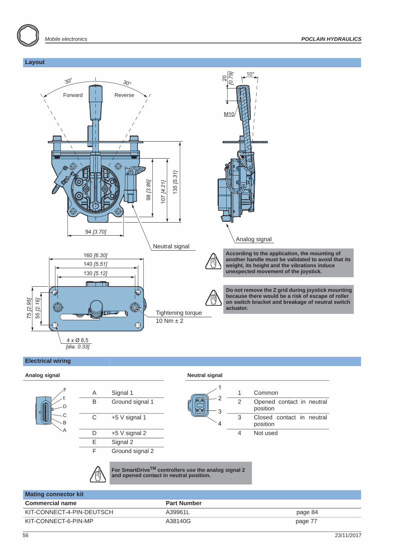
Layout
Electrical wiring
Analog signal Neutral signal
A Signal 1 1 CommonB Ground signal 1 2 Opened contact in neutral
positionC +5 V signal 1 3 Closed contact in neutral
positionD +5 V signal 2 4 Not usedE Signal 2F Ground signal 2
For SmartDriveTM controllers use the analog signal 2 and opened contact in neutral position.
Mating connector kitCommercial name Part NumberKIT-CONNECT-4-PIN-DEUTSCH A39961L page 84KIT-CONNECT-6-PIN-MP A38140G page 77
10°30° 30°
94 [3.70]
107
[4.2
1]
135
[5.3
1]
98 [3
.86]
130 [5.12]
140 [5.51]160 [6.30]
55 [2
.16]
75 [2
.95]
4 x Ø 8,5 [dia. 0.33]
20[0
.79]
M10
Tightening torque10 Nm ± 2
Forward Reverse
Neutral signalAnalog signal
According to the application, the mounting of another handle must be validated to avoid that its weight, its height and the vibrations induce unexpected movement of the joystick.
Do not remove the Z grid during joystick mounting because there would be a risk of escape of roller on switch bracket and breakage of neutral switch actuator.
F E
D
CBA
1
2
3
4
23/11/2017 57
POCLAIN HYDRAULICS Mobile electronics
Elec
tron
ic c
ontr
ol u
nits
Elec
tron
ic c
ompo
nent
sC
onne
ctor
sC
able
sD
ispl
ays
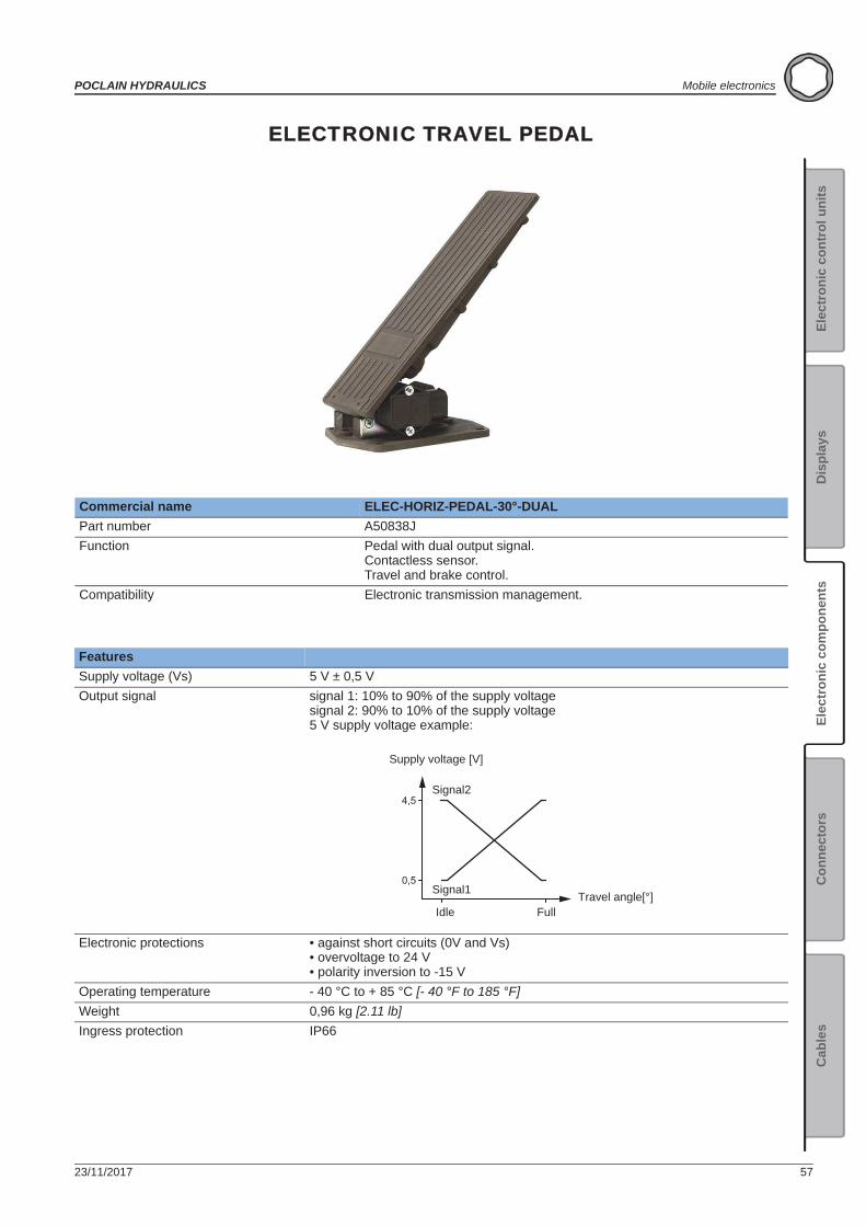
ELECTRONIC TRAVEL PEDAL
Commercial name ELEC-HORIZ-PEDAL-30°-DUALPart number A50838JFunction Pedal with dual output signal.
Contactless sensor.Travel and brake control.
Compatibility Electronic transmission management.
FeaturesSupply voltage (Vs) 5 V ± 0,5 VOutput signal signal 1: 10% to 90% of the supply voltage
signal 2: 90% to 10% of the supply voltage5 V supply voltage example:
Electronic protections • against short circuits (0V and Vs)• overvoltage to 24 V• polarity inversion to -15 V
Operating temperature - 40 °C to + 85 °C [- 40 °F to 185 °F]Weight 0,96 kg [2.11 lb]Ingress protection IP66
4,5
0,5
Signal2
Signal1
Full
Supply voltage [V]
IdleTravel angle[°]
58 23/11/2017
Mobile electronics POCLAIN HYDRAULICS
Electrical connectionPedal is delivered with a connection kit:Counter connector kit includes: • Connector
• Terminals• Wire seal• Cavity plug
AMP ref. 1-967616-1 (x1)AMP ref. 0-962885-5 (x7)AMP ref. 0-0967067-1 (x7)AMP ref. 967056-1 (x4)
To crimp correctly use: • Special crimping tool Tyco: 0-0539 635-1 • Wire gauge: AWG20 • External diameter of the wire: between1,29 mm and 1,6 mm
It is possible to connect a harness to use only 1 signal with connector Weather Pack: A51444S (for more details, see page 105).It is possible to connect a harness to use 2 signals with connector Deutsch: A51445T (for more details, see page 106).
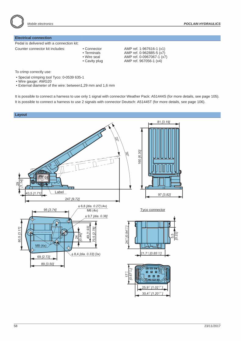
Layout
247 [9.72]
22°
30°
97 [3.82]
81 [3.19]
160
[6.3
0]
43,5 [1.71]
29 [1
.14]
95 [3.74]
80,5
[3.1
7]
89 [3.50]
69 [2.72] 8,4 [dia. 0.33] (3x)
70,5
[2.7
8]
49 [1
.93]
24[0
.96]
6,8 [dia. 0.27] (4x)
9,7 [dia. 0.38]
M6 (4x)
M8 (4x)
25,9 [1.02 ]+0,5 0
+0.02 0
30,4 [1.20 ]+0,5 0
+0.02 0
17
[0.6
7
]
+0,3
-0,2 +0
.01
-0.0
08
24
[0.9
4
]+0
,4 -0
,5+0
.016
-0.0
2
5,5
[0.2
2]
21,7 [0.85 ]+0,1 -0,2
+0.004 -0.008
Tyco connector
Label
23/11/2017 59
POCLAIN HYDRAULICS Mobile electronics
Elec
tron
ic c
ontr
ol u
nits
Elec
tron
ic c
ompo
nent
sC
onne
ctor
sC
able
sD
ispl
ays
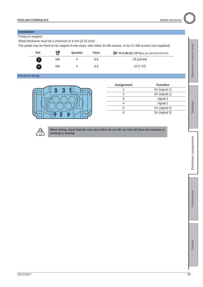
InstallationFixing on support:Sheet thickness must be a minimum of 4 mm [0.16 inch].The pedal may be fixed on its support in two ways; with either 4x M6 screws, or by 4 x M8 screws (not supplied).
Ref. Quantity Class N.m [lb.ft] ± 10 %(as per standard DIN 912)
M8 4 8.8 25 [18.44]
M6 4 8.8 10 [7.37]
Electrical wiring
Assignment Function1 5V (signal 1)2 0V (signal 1)3 signal 24 signal 15 0V (signal 2)6 5V (signal 2)
When wiring, check that the wire can neither be cut off, nor torn off when the machine is working or moving.
1
2
60 23/11/2017
Mobile electronics POCLAIN HYDRAULICS
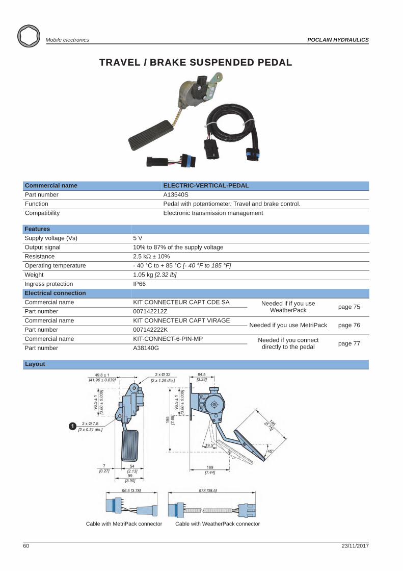
TRAVEL / BRAKE SUSPENDED PEDAL
Commercial name ELECTRIC-VERTICAL-PEDALPart number A13540SFunction Pedal with potentiometer. Travel and brake control.Compatibility Electronic transmission management
FeaturesSupply voltage (Vs) 5 VOutput signal 10% to 87% of the supply voltageResistance 2.5 k ± 10%Operating temperature - 40 °C to + 85 °C [- 40 °F to 185 °F]Weight 1.05 kg [2.32 lb]Ingress protection IP66Electrical connectionCommercial name KIT CONNECTEUR CAPT CDE SA Needed if if you use
WeatherPack page 75Part number 007142212ZCommercial name KIT CONNECTEUR CAPT VIRAGE
Needed if you use MetriPack page 76Part number 007142222KCommercial name KIT-CONNECT-6-PIN-MP Needed if you connect
directly to the pedal page 77Part number A38140G
Layout
Cable with MetriPack connector Cable with WeatherPack connector
23/11/2017 61
POCLAIN HYDRAULICS Mobile electronics
Elec
tron
ic c
ontr
ol u
nits
Elec
tron
ic c
ompo
nent
sC
onne
ctor
sC
able
sD
ispl
ays
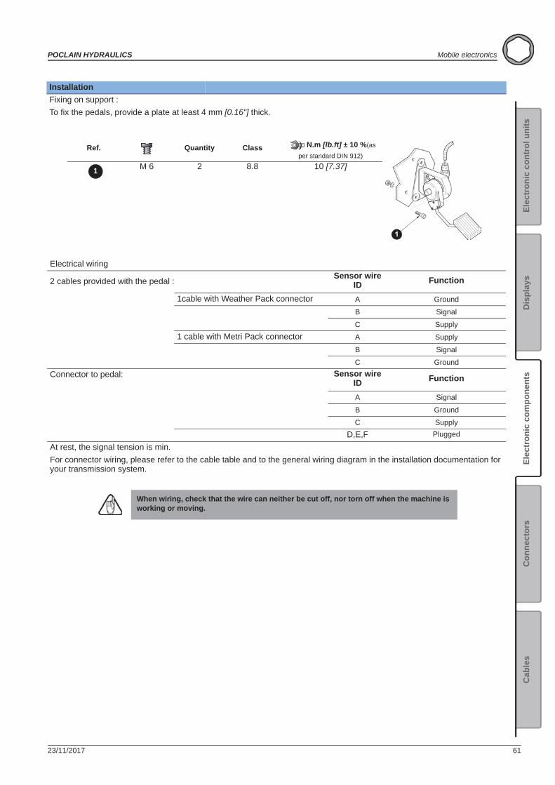
InstallationFixing on support :To fix the pedals, provide a plate at least 4 mm [0.16"] thick.
Ref. Quantity Class N.m [lb.ft] ± 10 %(as
per standard DIN 912)
M 6 2 8.8 10 [7.37]
Electrical wiring
2 cables provided with the pedal : Sensor wire ID Function
1cable with Weather Pack connector A Ground
B Signal
C Supply1 cable with Metri Pack connector A Supply
B Signal
C GroundConnector to pedal: Sensor wire
ID Function
A Signal
B Ground
C SupplyD,E,F Plugged
At rest, the signal tension is min.For connector wiring, please refer to the cable table and to the general wiring diagram in the installation documentation for your transmission system.
When wiring, check that the wire can neither be cut off, nor torn off when the machine is working or moving.
1
62 23/11/2017
Mobile electronics POCLAIN HYDRAULICS
Connectors
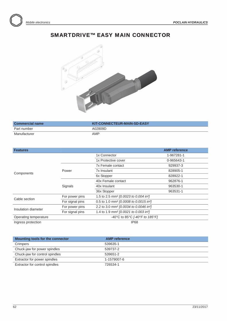
SMARTDRIVE™ EASY MAIN CONNECTOR
Commercial name KIT-CONNECTEUR-MAIN-SD-EASYPart number A02809DManufacturer AMP
Features AMP reference
Components
1x Connector 1-967281-11x Protective cover 0-965643-1
Power7x Female contact 929937-37x Insulant 828905-16x Stopper 828922-1
Signals40x Female contact 962876-140x Insulant 963530-136x Stopper 963531-1
Cable sectionFor power pins 1.5 to 2.5 mm² [0.0023 to 0.004 in²]For signal pins 0.5 to 1.0 mm² [0.0008 to 0.0015 in²]
Insulation diameterFor power pins 2.2 to 3.0 mm² [0.0034 to 0.0046 in²]For signal pins 1.4 to 1.9 mm² [0.0021 to 0.003 in²]
Operating temperature -40°C to 85°C [-40°F to 185°F]Ingress protection IP68
Mounting tools for the connector AMP reference Crimpers 539635-1 Chuck-jaw for power spindles 539737-2 Chuck-jaw for control spindles 539651-2 Extractor for power spindles 1-1579007-6 Extractor for control spindles 726534-1
23/11/2017 63
POCLAIN HYDRAULICS Mobile electronics
Elec
tron
ic c
ontr
ol u
nits
Elec
tron
ic c
ompo
nent
sC
onne
ctor
sC
able
sD
ispl
ays
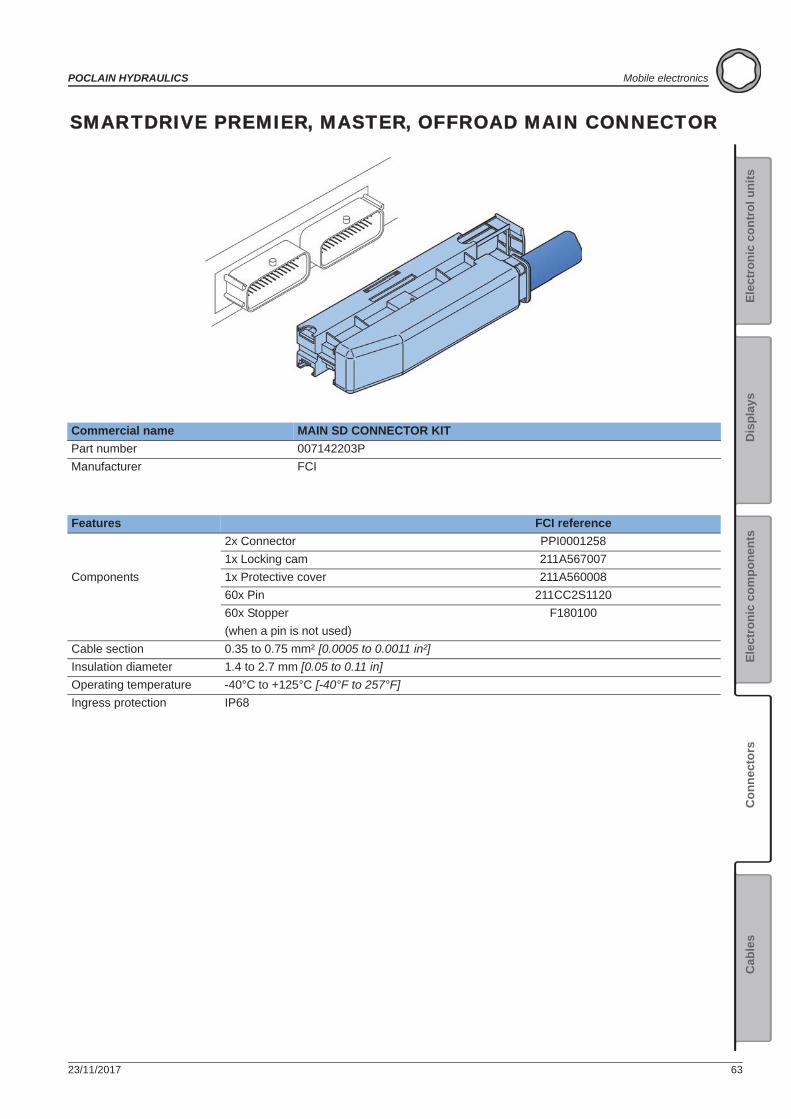
SMARTDRIVE PREMIER, MASTER, OFFROAD MAIN CONNECTOR
Commercial name MAIN SD CONNECTOR KITPart number 007142203PManufacturer FCI
Features FCI reference
Components
2x Connector PPI00012581x Locking cam 211A5670071x Protective cover 211A56000860x Pin 211CC2S112060x Stopper F180100(when a pin is not used)
Cable section 0.35 to 0.75 mm² [0.0005 to 0.0011 in²]Insulation diameter 1.4 to 2.7 mm [0.05 to 0.11 in]Operating temperature -40°C to +125°C [-40°F to 257°F]Ingress protection IP68
64 23/11/2017
Mobile electronics POCLAIN HYDRAULICS
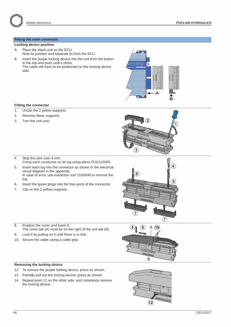
Fitting the main connectorLocking device positionA. Place the black unit on the ECU.
Note its position and separate its from the ECU.B. Insert the purple locking device into the unit from the botton
to the top and push until it clicks. The cable will have to be positioned on the locking device side.
Fitting the connector1. Unclip the 2 yellow supports.2. Remove these supports.3. Turn the unit over.
4. Strip the wire over 4 mm. Crimp each conductor on its lug using pliers FCI211S005.
5. Insert each lug into the connector as shown in the electrical circuit diagram in the appendix. In case of error, use extraction tool 210S048 to remove the lug.
6. Insert the green plugs into the free ports of the connector.7. Clip on the 2 yellow supports.
8. Position the cover and lower it. The cover tab (A) must be on the right of the unit tab (B).
9. Lock it by pulling on it until there is a click.10. Secure the cable uising a cable grip.
Removing the locking device12. To remove the purple locking device, press as shown.13. Partially pull out the locking device, press as shown.14. Repeat point 12 on the other side, and completely remove
the locking device.
23/11/2017 65
POCLAIN HYDRAULICS Mobile electronics
Elec
tron
ic c
ontr
ol u
nits
Elec
tron
ic c
ompo
nent
sC
onne
ctor
sC
able
sD
ispl
ays
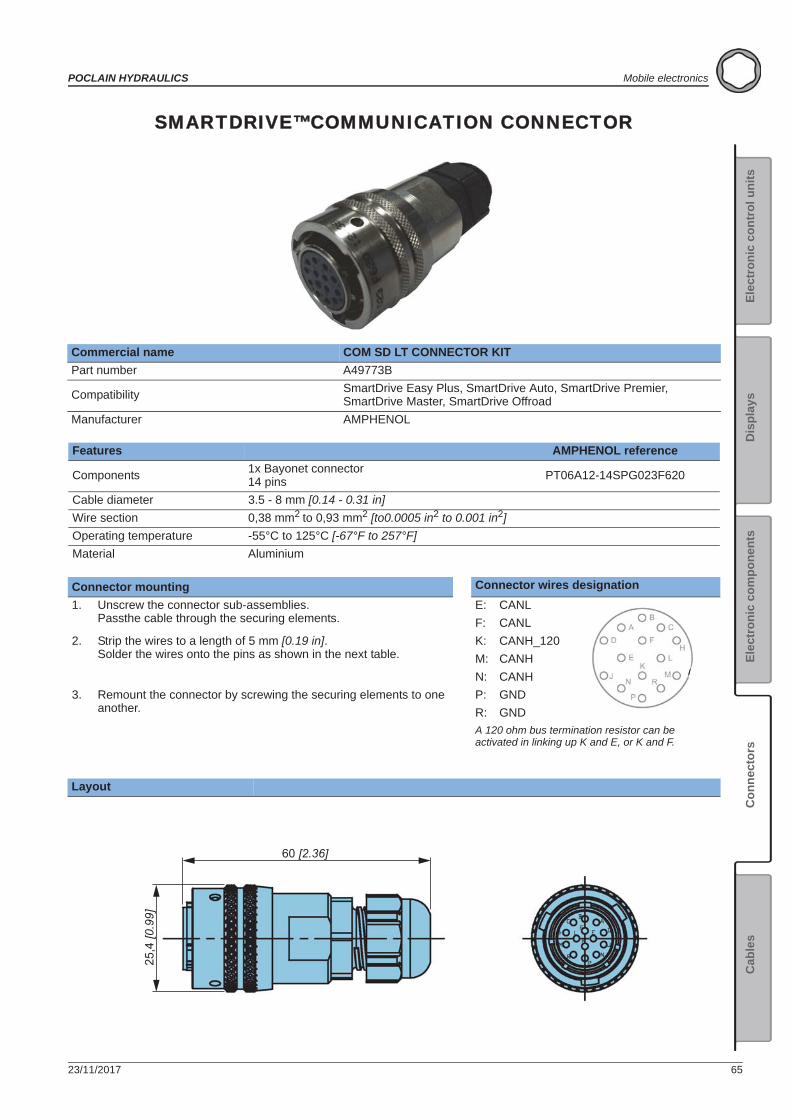
SMARTDRIVE™COMMUNICATION CONNECTOR
Commercial name COM SD LT CONNECTOR KITPart number A49773B
Compatibility SmartDrive Easy Plus, SmartDrive Auto, SmartDrive Premier, SmartDrive Master, SmartDrive Offroad
Manufacturer AMPHENOL
Features AMPHENOL reference
Components 1x Bayonet connector14 pins PT06A12-14SPG023F620
Cable diameter 3.5 - 8 mm [0.14 - 0.31 in]Wire section 0,38 mm2 to 0,93 mm2 [to0.0005 in2 to 0.001 in2]Operating temperature -55°C to 125°C [-67°F to 257°F]Material Aluminium
Connector mounting Connector wires designation1. Unscrew the connector sub-assemblies.
Passthe cable through the securing elements.E: CANLF: CANL
2. Strip the wires to a length of 5 mm [0.19 in]. Solder the wires onto the pins as shown in the next table.
K: CANH_120M: CANHN: CANH
3. Remount the connector by screwing the securing elements to one another.
P: GNDR: GNDA 120 ohm bus termination resistor can be activated in linking up K and E, or K and F.
Layout
60 [2.36]
25,4
[0.9
9]
66 23/11/2017
Mobile electronics POCLAIN HYDRAULICS
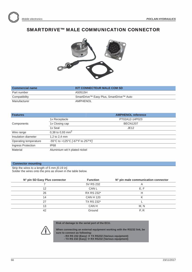
SMARTDRIVE™ MALE COMMUNICATION CONNECTOR
Commercial name KIT CONNECTEUR MALE COM SDPart number A50515HCompatibility SmartDrive™ Easy Plus, SmartDrive™ AutoManufacturer AMPHENOL
Features AMPHENOL reference
Components1x Receptacle PT02A12-14P0231x Closing cap BECN12071x Seal JE12
Wire range 0,38 to 0,93 mm2
Insulation diameter 1,2 to 2,4 mmOperating temperature -55°C to +125°C [-67°F to 257°F]Ingress Protection IP68Material Aluminium wit h plated nickel
Connector mountingStrip the wires to a length of 5 mm [0.19 in]. Solder the wires onto the pins as shown in the table below.
N° pin SD Easy Plus connector Function N° pin male communication connector7 5V RS 232 A
12 CAN L E, F26 RX RS 232* H14 CAN H 120 K27 TX RS 232* L13 CAN H M, N42 Ground P, R
Risk of damage to the serial port of the ECU.
When connecting an external equipment working with the RS232 link, be sure to connect as following:
- RX RS 232 (Easy) TX RS232 (Various equipment)- TX RS 232 (Easy) RX RS232 (Various equipment)
23/11/2017 67
POCLAIN HYDRAULICS Mobile electronics
Elec
tron
ic c
ontr
ol u
nits
Elec
tron
ic c
ompo
nent
sC
onne
ctor
sC
able
sD
ispl
ays
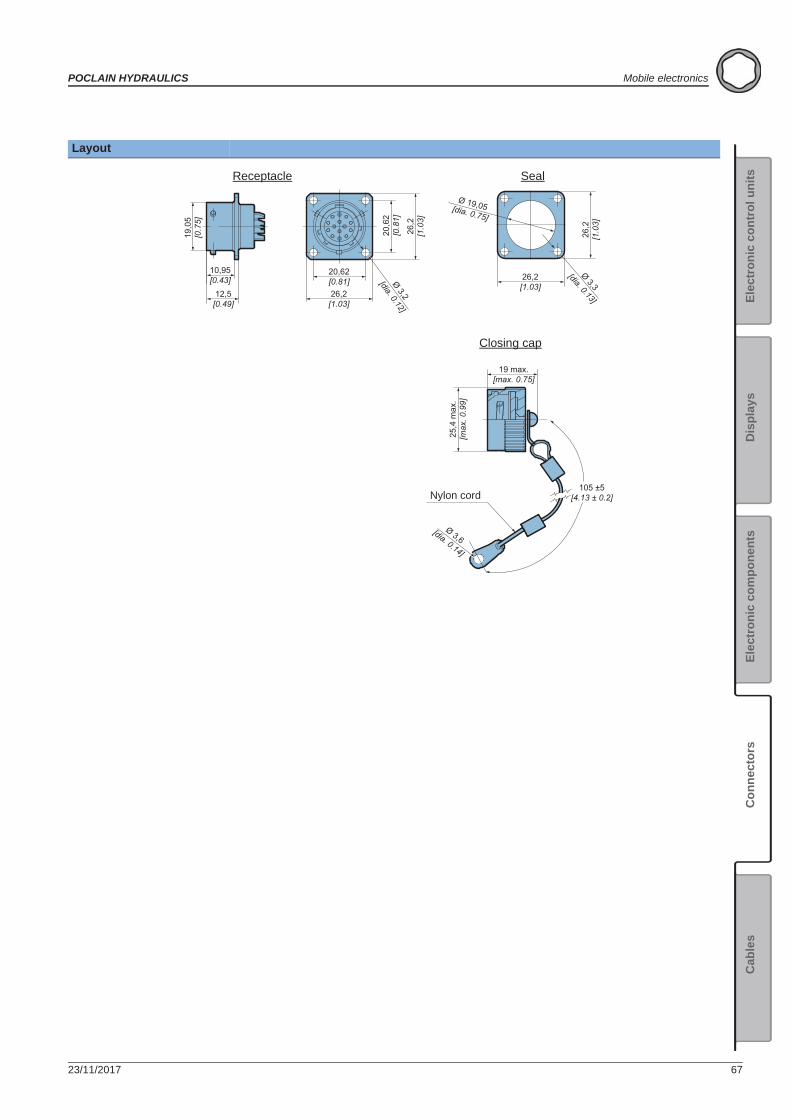
Layout
26,2
[1.0
3]
26,2[1.03]
20,62[0.81]
20,6
2[0
.81]
Ø 3,2
[dia. 0.12]
10,95[0.43]
12,5[0.49]
19,0
5[0
.75]
26,2[1.03]
26,2
[1.0
3]
Ø 19,05[dia. 0.75]
105 ±5[4.13 ± 0.2]
25,4
max
.[m
ax. 0
.99]
19 max.[max. 0.75]
Ø 3,3
[dia. 0.13]
Ø 3,6[dia. 0.14]
Seal
Closing cap
Receptacle
Nylon cord
68 23/11/2017
Mobile electronics POCLAIN HYDRAULICS
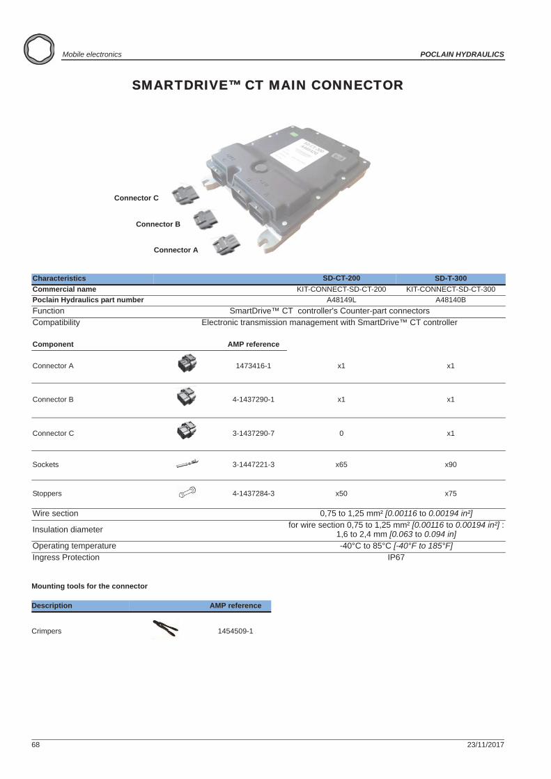
SMARTDRIVE™ CT MAIN CONNECTOR
Mounting tools for the connector
Characteristics SD-CT-200 SD-T-300Commercial name KIT-CONNECT-SD-CT-200 KIT-CONNECT-SD-CT-300Poclain Hydraulics part number A48149L A48140BFunction SmartDrive™ CT controller's Counter-part connectorsCompatibility Electronic transmission management with SmartDrive™ CT controller
Component AMP reference
Connector A 1473416-1 x1 x1
Connector B 4-1437290-1 x1 x1
Connector C 3-1437290-7 0 x1
Sockets 3-1447221-3 x65 x90
Stoppers 4-1437284-3 x50 x75
Wire section 0,75 to 1,25 mm² [0.00116 to 0.00194 in²]
Insulation diameter for wire section 0,75 to 1,25 mm² [0.00116 to 0.00194 in²] :1,6 to 2,4 mm [0.063 to 0.094 in]
Operating temperature -40°C to 85°C [-40°F to 185°F]Ingress Protection IP67
Description AMP reference
Crimpers 1454509-1
Connector C
Connector B
Connector A
23/11/2017 69
POCLAIN HYDRAULICS Mobile electronics
Elec
tron
ic c
ontr
ol u
nits
Elec
tron
ic c
ompo
nent
sC
onne
ctor
sC
able
sD
ispl
ays
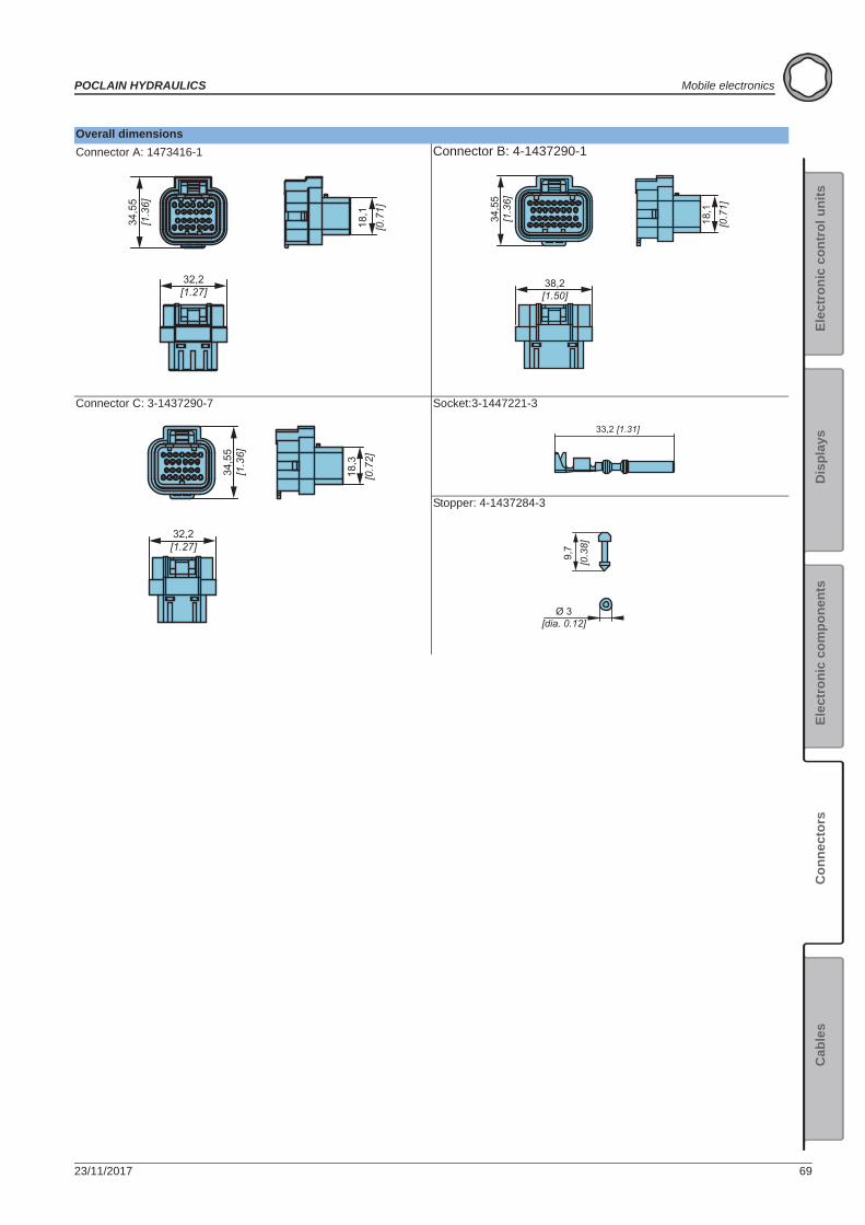
Overall dimensionsConnector A: 1473416-1 Connector B: 4-1437290-1
Connector C: 3-1437290-7 Socket:3-1447221-3
Stopper: 4-1437284-3
34,5
5[1
.36]
18,1
[0.7
1]
32,2[1.27]
34,5
5[1
.36]
18,1
[0.7
1]
38,2[1.50]
34,5
5[1
.36]
18,3
[0.7
2]
32,2[1.27]
33,2 [1.31]
9,7
[0.3
8]
Ø 3[dia. 0.12]
70 23/11/2017
Mobile electronics POCLAIN HYDRAULICS
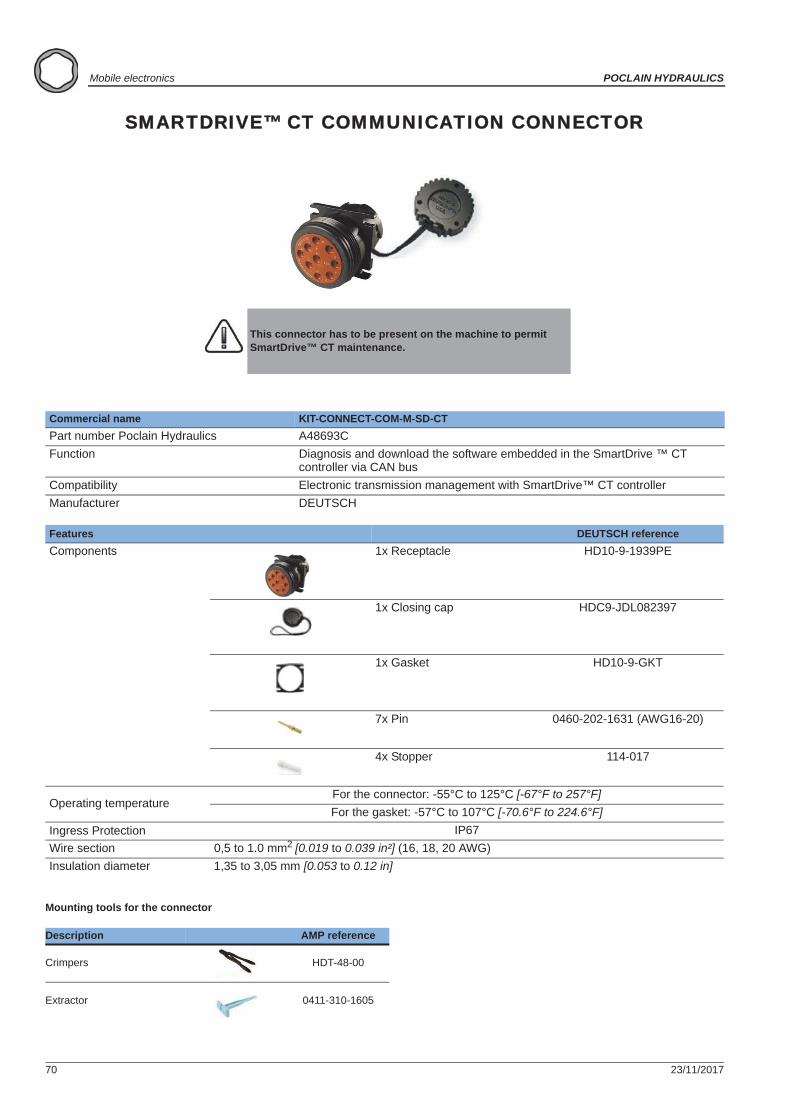
SMARTDRIVE™ CT COMMUNICATION CONNECTOR
Mounting tools for the connector
This connector has to be present on the machine to permit SmartDrive™ CT maintenance.
Commercial name KIT-CONNECT-COM-M-SD-CTPart number Poclain Hydraulics A48693CFunction Diagnosis and download the software embedded in the SmartDrive ™ CT
controller via CAN busCompatibility Electronic transmission management with SmartDrive™ CT controllerManufacturer DEUTSCH
Features DEUTSCH referenceComponents 1x Receptacle HD10-9-1939PE
1x Closing cap HDC9-JDL082397
1x Gasket HD10-9-GKT
7x Pin 0460-202-1631 (AWG16-20)
4x Stopper 114-017
Operating temperatureFor the connector: -55°C to 125°C [-67°F to 257°F]For the gasket: -57°C to 107°C [-70.6°F to 224.6°F]
Ingress Protection IP67Wire section 0,5 to 1.0 mm2 [0.019 to 0.039 in²] (16, 18, 20 AWG)Insulation diameter 1,35 to 3,05 mm [0.053 to 0.12 in]
Description AMP reference
Crimpers HDT-48-00
Extractor 0411-310-1605
23/11/2017 71
POCLAIN HYDRAULICS Mobile electronics
Elec
tron
ic c
ontr
ol u
nits
Elec
tron
ic c
ompo
nent
sC
onne
ctor
sC
able
sD
ispl
ays
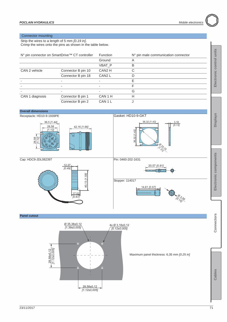
Connector mountingStrip the wires to a length of 5 mm [0.19 in]. Crimp the wires onto the pins as shown in the table below.
N° pin connector on SmartDrive™ CT controller Function N° pin male communication connectorGround AVBAT_P B
CAN 2 vehicle Connector B pin 10 CAN2 H CConnector B pin 18 CAN2 L D
- - - E- - - F- - - GCAN 1 diagnosis Connector B pin 1 CAN 1 H H
Connector B pin 2 CAN 1 L J
Overall dimensionsReceptacle: HD10-9-1939PE Gasket: HD10-9-GKT
Cap: HDC9-JDL082397 Pin: 0460-202-1631
Stopper: 114017
Panel cutout
42,16 [1.66]28,58[1.12]
28,5
8[1
.12]
36,5 [1.44] 36,32 [1.43] 3,18[0.13]
36,3
2 [1
.43]
Ø 33,15[1.31]
40,1
3 [1
.58]
17,02[0.67]
12,37[0.49]
20,57 [0.81]
14,61 [0.57]
Ø 3,56[0.14]
28,58±0,12[1.12±0,005]
28,5
8±0,
12[1
.12±
0,00
5]
Ø 35,38±0,12[1.39±0,005]
4x Ø 3,18±0,12[0.12±0,005]
Maximum panel thickness: 6,35 mm [0.25 in]
72 23/11/2017
Mobile electronics POCLAIN HYDRAULICS
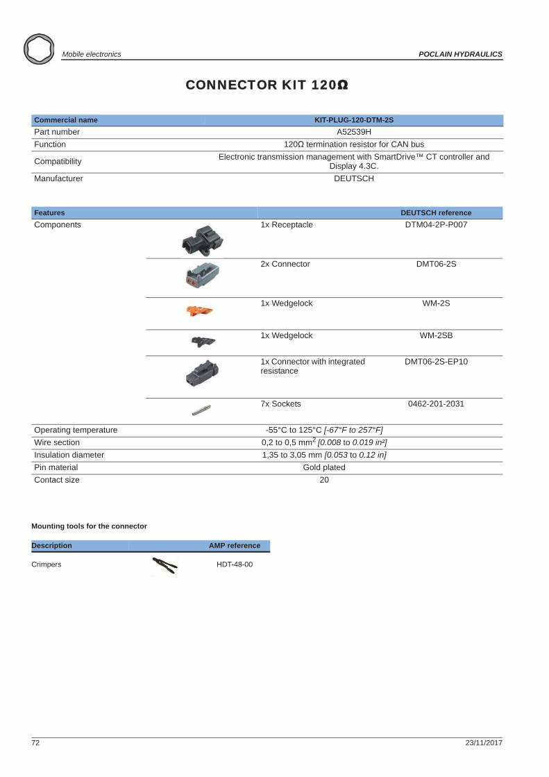
CONNECTOR KIT 120
Mounting tools for the connector
Commercial name KIT-PLUG-120-DTM-2SPart number A52539HFunction 120 termination resistor for CAN bus
Compatibility Electronic transmission management with SmartDrive™ CT controller and Display 4.3C.
Manufacturer DEUTSCH
Features DEUTSCH referenceComponents 1x Receptacle DTM04-2P-P007
2x Connector DMT06-2S
1x Wedgelock WM-2S
1x Wedgelock WM-2SB
1x Connector with integrated resistance
DMT06-2S-EP10
7x Sockets 0462-201-2031
Operating temperature -55°C to 125°C [-67°F to 257°F]Wire section 0,2 to 0,5 mm2 [0.008 to 0.019 in²]Insulation diameter 1,35 to 3,05 mm [0.053 to 0.12 in]Pin material Gold platedContact size 20
Description AMP reference
Crimpers HDT-48-00
23/11/2017 73
POCLAIN HYDRAULICS Mobile electronics
Elec
tron
ic c
ontr
ol u
nits
Elec
tron
ic c
ompo
nent
sC
onne
ctor
sC
able
sD
ispl
ays
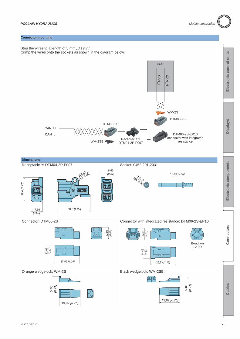
Connector mounting
Strip the wires to a length of 5 mm [0.19 in]. Crimp the wires onto the sockets as shown in the diagram below.
DimensionsReceptacle Y: DTM04-2P-P007 Socket: 0462-201-2031
Connector: DTM06-2S Connector with integrated resistance: DTM06-2S-EP10
Orange wedgelock: WM-2S Black wedgelock: WM-2SB
CAN_H
CAN_L
DTM06-2S
WM-2SBReceptacle Y
DTM04-2P-P007
DTM06-2S
WM-2S
DTM06-2S-EP10connector with integrated
resistance
CA
N_H
CAN
_L
ECU
6543 2 1
78
12
9
11
10XX
37,4
[1.4
7]
17,56[0.69]
50,8 [1.99]
Ø 5,08
[dia. 0.20]5,59
[0.22] 16,43 [0.65]Ø 2,56
[dia. 0.10]
27,56 [1.08]
12,0
7[0
.47]
12,9
1[0
.51]
14,4
5[0
.57]
28,83 [1.13]
12,9
[0.5
1]
Bouchon 120
19,02 [0.75]
5,46
[0.2
1]
5,46
[0.2
1]
19,02 [0.75]
74 23/11/2017
Mobile electronics POCLAIN HYDRAULICS
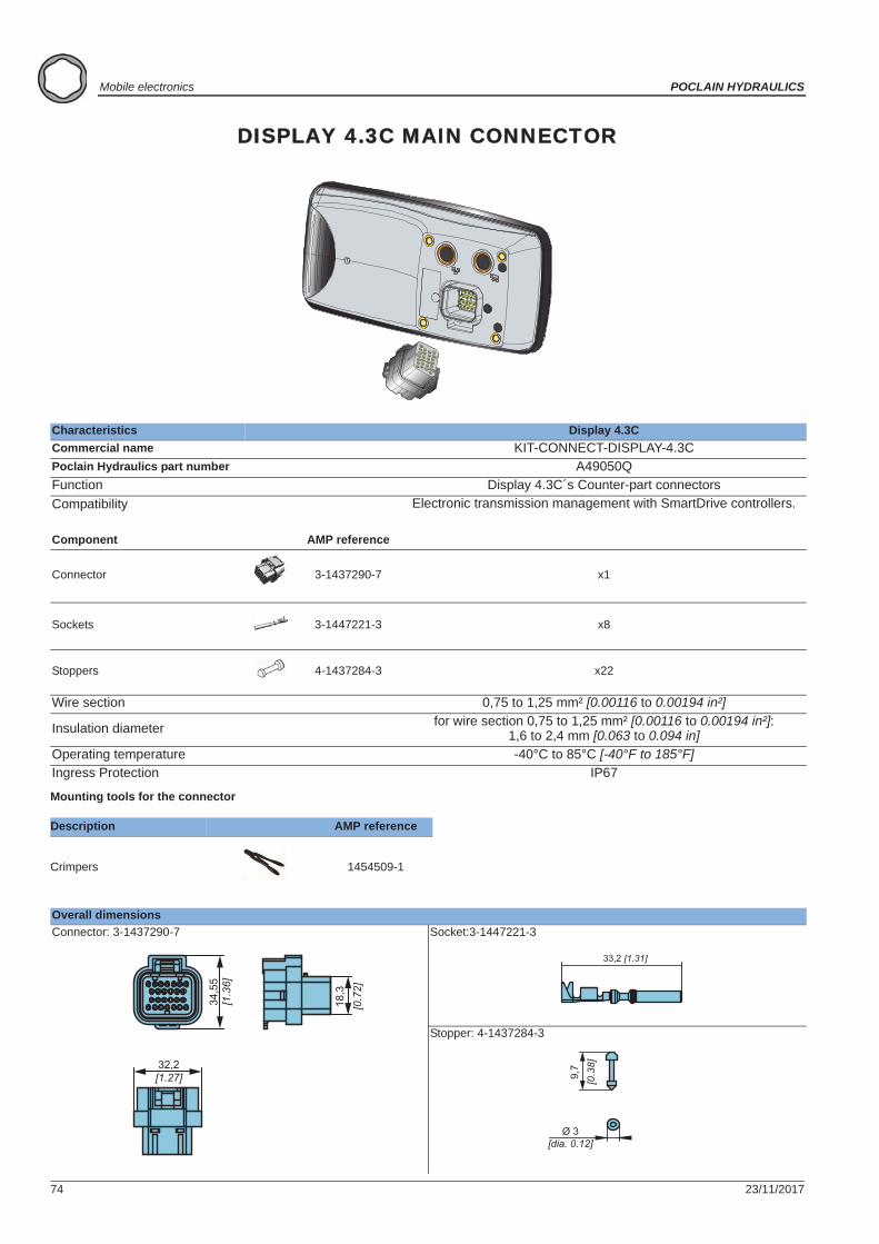
DISPLAY 4.3C MAIN CONNECTOR
Mounting tools for the connector
Characteristics Display 4.3CCommercial name KIT-CONNECT-DISPLAY-4.3CPoclain Hydraulics part number A49050QFunction Display 4.3C´s Counter-part connectorsCompatibility Electronic transmission management with SmartDrive controllers.
Component AMP reference
Connector 3-1437290-7 x1
Sockets 3-1447221-3 x8
Stoppers 4-1437284-3 x22
Wire section 0,75 to 1,25 mm² [0.00116 to 0.00194 in²]
Insulation diameter for wire section 0,75 to 1,25 mm² [0.00116 to 0.00194 in²]:1,6 to 2,4 mm [0.063 to 0.094 in]
Operating temperature -40°C to 85°C [-40°F to 185°F]Ingress Protection IP67
Description AMP reference
Crimpers 1454509-1
Overall dimensionsConnector: 3-1437290-7 Socket:3-1447221-3
Stopper: 4-1437284-3
34,5
5[1
.36]
18,3
[0.7
2]
32,2[1.27]
33,2 [1.31]
9,7
[0.3
8]
Ø 3[dia. 0.12]

23/11/2017 75
POCLAIN HYDRAULICS Mobile electronics
Elec
tron
ic c
ontr
ol u
nits
Elec
tron
ic c
ompo
nent
sC
onne
ctor
sC
able
sD
ispl
ays
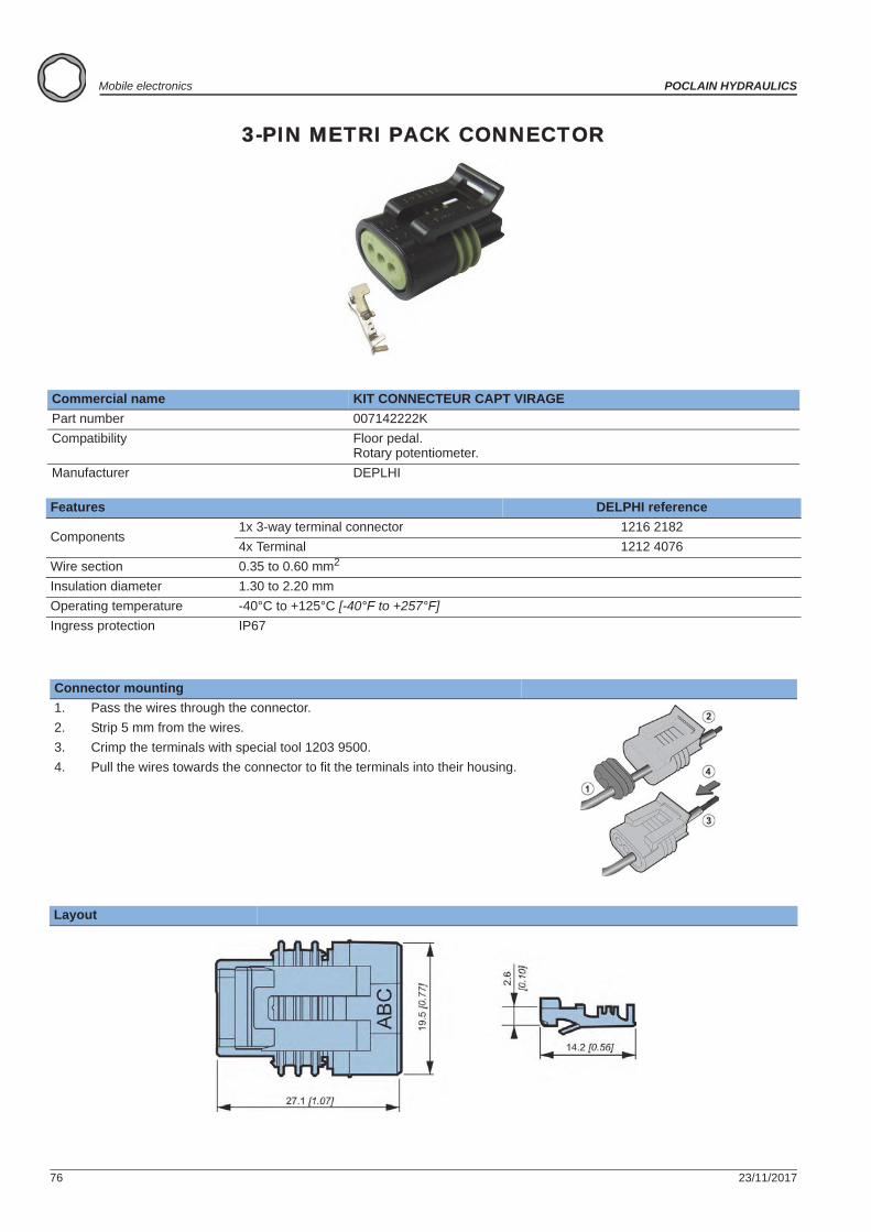
3-PIN WEATHER PACK CONNECTOR
Commercial name KIT CONNECTEUR CAPT CDE SAPart number 007142212ZCompatibility Floor pedal.
Suspended pedal.Swash plate sensor.Rotary potentiometer.
FeaturesManufacturer DELPHI reference
Components1x 3-way male connector 1201 57933x Female contact 1208 91883x Seal 1201 5323
Wire section 0.5 to 0.8 mm2
Insulation diameter 2 to 2.9 mmOperating temperature -40°C to +125°C [-40°F to +257°F]Ingress protection IP 67
Connector mountingLocking device position1. Fit a seal on each wire.2. Strip 5 mm [0.19 in] off the wires.3. Crimp the terminals with the 1201 4254 Packard Electric pliers,
pinching the seal with the lug.4. Plug the terminal into its compartment. If a terminal is wrongly
inserted, use extraction tool Ref 1201 4012 to remove it.Fold down the connector latch.
Layout
SealFemale contact
76 23/11/2017
Mobile electronics POCLAIN HYDRAULICS
3-PIN METRI PACK CONNECTOR
Commercial name KIT CONNECTEUR CAPT VIRAGEPart number 007142222KCompatibility Floor pedal.
Rotary potentiometer.Manufacturer DEPLHI
Features DELPHI reference
Components1x 3-way terminal connector 1216 21824x Terminal 1212 4076
Wire section 0.35 to 0.60 mm2
Insulation diameter 1.30 to 2.20 mmOperating temperature -40°C to +125°C [-40°F to +257°F]Ingress protection IP67
Connector mounting1. Pass the wires through the connector.2. Strip 5 mm from the wires.3. Crimp the terminals with special tool 1203 9500.4. Pull the wires towards the connector to fit the terminals into their housing.
Layout
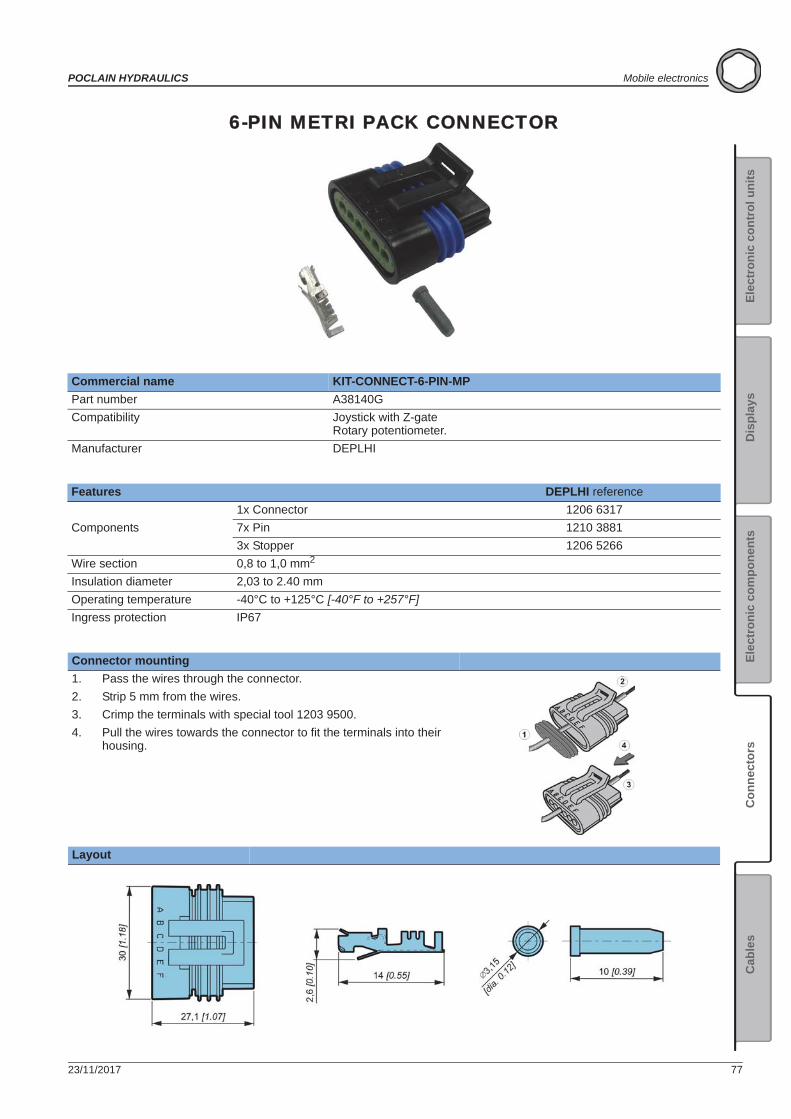
23/11/2017 77
POCLAIN HYDRAULICS Mobile electronics
Elec
tron
ic c
ontr
ol u
nits
Elec
tron
ic c
ompo
nent
sC
onne
ctor
sC
able
sD
ispl
ays
6-PIN METRI PACK CONNECTOR
Commercial name KIT-CONNECT-6-PIN-MPPart number A38140GCompatibility Joystick with Z-gate
Rotary potentiometer.Manufacturer DEPLHI
Features DEPLHI reference
Components1x Connector 1206 63177x Pin 1210 38813x Stopper 1206 5266
Wire section 0,8 to 1,0 mm2
Insulation diameter 2,03 to 2.40 mmOperating temperature -40°C to +125°C [-40°F to +257°F]Ingress protection IP67
Connector mounting1. Pass the wires through the connector.2. Strip 5 mm from the wires.3. Crimp the terminals with special tool 1203 9500.4. Pull the wires towards the connector to fit the terminals into their
housing.
Layout
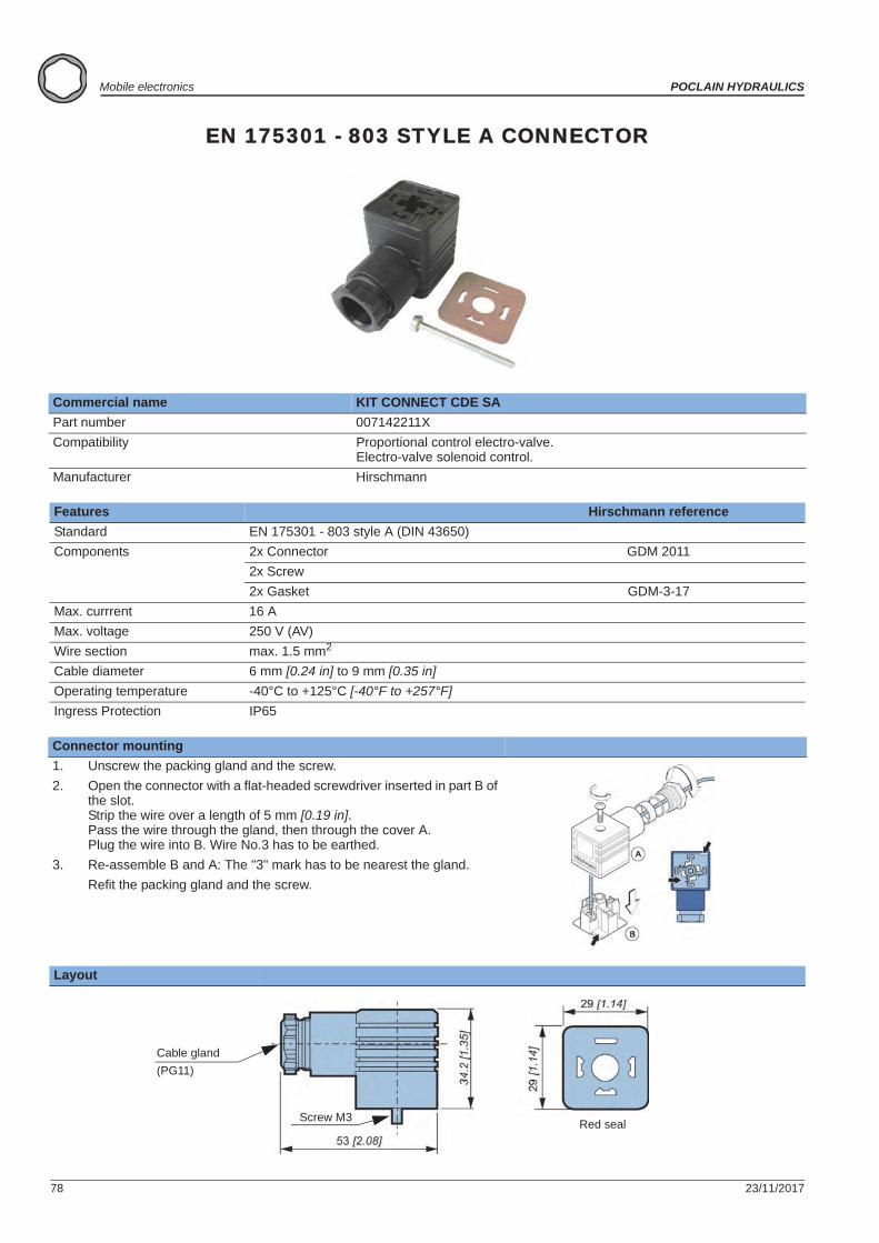
78 23/11/2017
Mobile electronics POCLAIN HYDRAULICS
EN 175301 - 803 STYLE A CONNECTOR
Commercial name KIT CONNECT CDE SAPart number 007142211XCompatibility Proportional control electro-valve.
Electro-valve solenoid control.Manufacturer Hirschmann
Features Hirschmann referenceStandard EN 175301 - 803 style A (DIN 43650)Components 2x Connector GDM 2011
2x Screw2x Gasket GDM-3-17
Max. currrent 16 AMax. voltage 250 V (AV)Wire section max. 1.5 mm2
Cable diameter 6 mm [0.24 in] to 9 mm [0.35 in]Operating temperature -40°C to +125°C [-40°F to +257°F]Ingress Protection IP65
Connector mounting1. Unscrew the packing gland and the screw.2. Open the connector with a flat-headed screwdriver inserted in part B of
the slot.Strip the wire over a length of 5 mm [0.19 in].Pass the wire through the gland, then through the cover A.Plug the wire into B. Wire No.3 has to be earthed.
3. Re-assemble B and A: The "3" mark has to be nearest the gland.Refit the packing gland and the screw.
Layout
Red sealScrew M3
Cable gland(PG11)
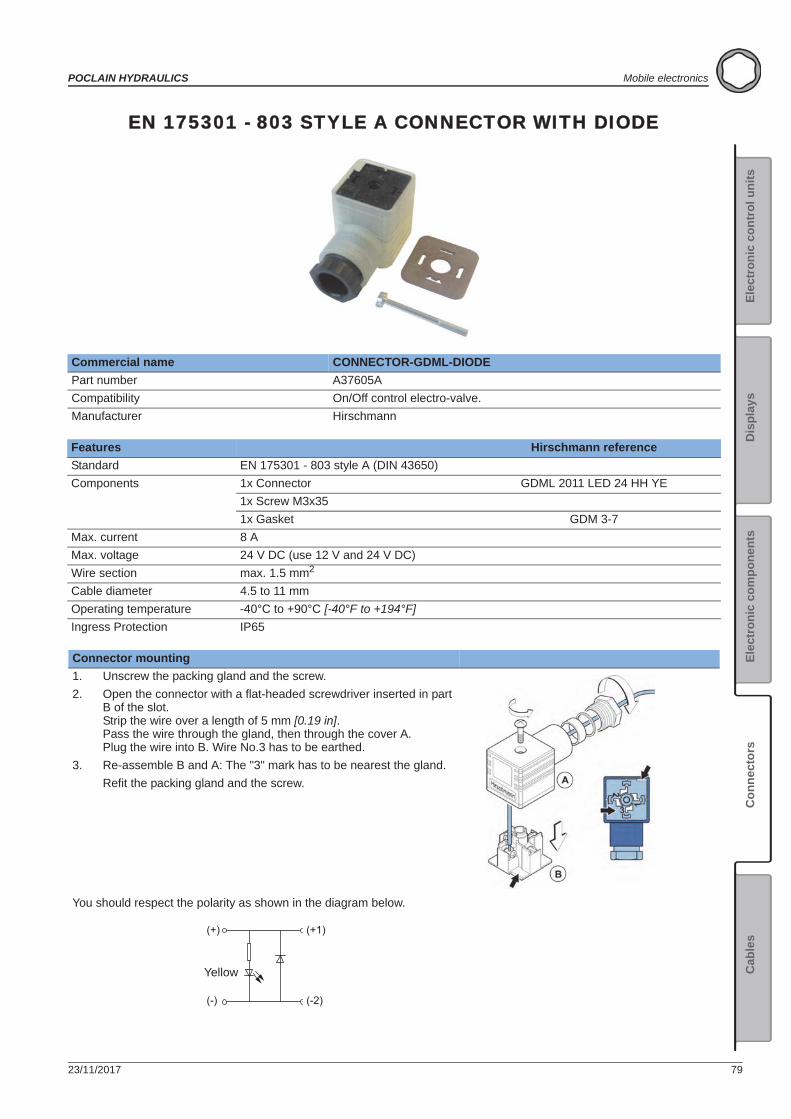
23/11/2017 79
POCLAIN HYDRAULICS Mobile electronics
Elec
tron
ic c
ontr
ol u
nits
Elec
tron
ic c
ompo
nent
sC
onne
ctor
sC
able
sD
ispl
ays
EN 175301 - 803 STYLE A CONNECTOR WITH DIODE
Commercial name CONNECTOR-GDML-DIODEPart number A37605ACompatibility On/Off control electro-valve.Manufacturer Hirschmann
Features Hirschmann referenceStandard EN 175301 - 803 style A (DIN 43650)Components 1x Connector GDML 2011 LED 24 HH YE
1x Screw M3x351x Gasket GDM 3-7
Max. current 8 AMax. voltage 24 V DC (use 12 V and 24 V DC)Wire section max. 1.5 mm2
Cable diameter 4.5 to 11 mmOperating temperature -40°C to +90°C [-40°F to +194°F]Ingress Protection IP65
Connector mounting1. Unscrew the packing gland and the screw.2. Open the connector with a flat-headed screwdriver inserted in part
B of the slot.Strip the wire over a length of 5 mm [0.19 in].Pass the wire through the gland, then through the cover A.Plug the wire into B. Wire No.3 has to be earthed.
3. Re-assemble B and A: The "3" mark has to be nearest the gland.Refit the packing gland and the screw.
You should respect the polarity as shown in the diagram below.
(+)
(-)
(+1)
(-2)
Yellow
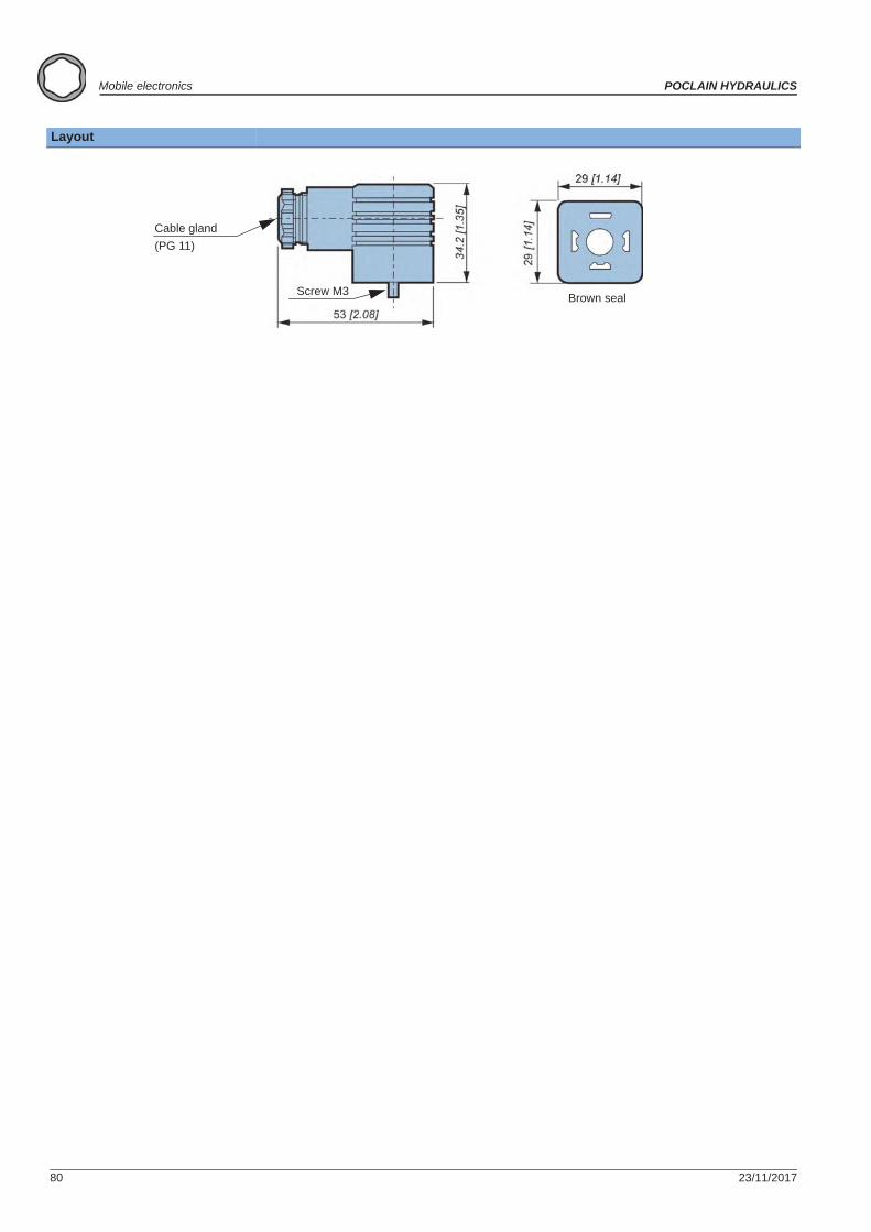
80 23/11/2017
Mobile electronics POCLAIN HYDRAULICS
Layout
Brown sealScrew M3
Cable gland(PG 11)
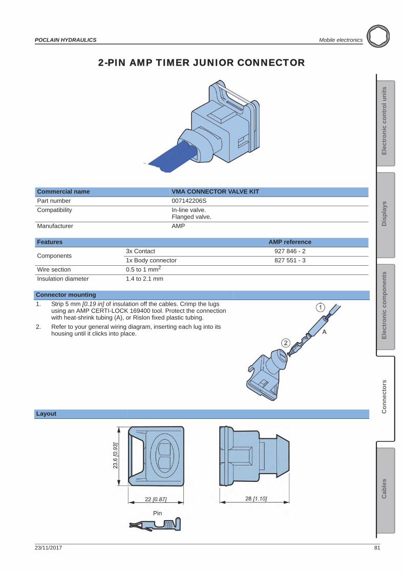
23/11/2017 81
POCLAIN HYDRAULICS Mobile electronics
Elec
tron
ic c
ontr
ol u
nits
Elec
tron
ic c
ompo
nent
sC
onne
ctor
sC
able
sD
ispl
ays
2-PIN AMP TIMER JUNIOR CONNECTOR
Commercial name VMA CONNECTOR VALVE KITPart number 007142206SCompatibility In-line valve.
Flanged valve.Manufacturer AMP
Features AMP reference
Components3x Contact 927 846 - 21x Body connector 827 551 - 3
Wire section 0.5 to 1 mm2
Insulation diameter 1.4 to 2.1 mm
Connector mounting1. Strip 5 mm [0.19 in] of insulation off the cables. Crimp the lugs
using an AMP CERTI-LOCK 169400 tool. Protect the connection with heat-shrink tubing (A), or Rislon fixed plastic tubing.
2. Refer to your general wiring diagram, inserting each lug into its housing until it clicks into place.
Layout
Pin
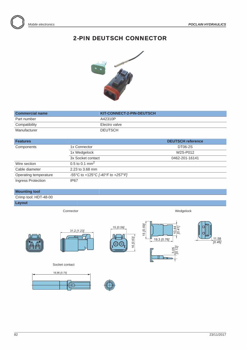
82 23/11/2017
Mobile electronics POCLAIN HYDRAULICS
2-PIN DEUTSCH CONNECTOR
Commercial name KIT-CONNECT-2-PIN-DEUTSCHPart number A42310PCompatibility Electro valveManufacturer DEUTSCH
Features DEUTSCH referenceComponents 1x Connector DT06-2S
1x Wedgelock W2S-P0123x Socket contact 0462-201-16141
Wire section 0.5 to 0.1 mm2
Cable diameter 2.23 to 3.68 mmOperating temperature -55°C to +125°C [-40°F to +257°F]Ingress Protection IP67
Mounting toolCrimp tool: HDT-48-00Layout
15 [0.59]
16 [0
.63]
31,2 [1.23]
11,58
10,4
4[0
.41]
19,3 [0.76]
15 [0
.59]
[0.46]
3,05
[0.1
2]
18,98 [0.75]
Connector Wedgelock
Socket contact
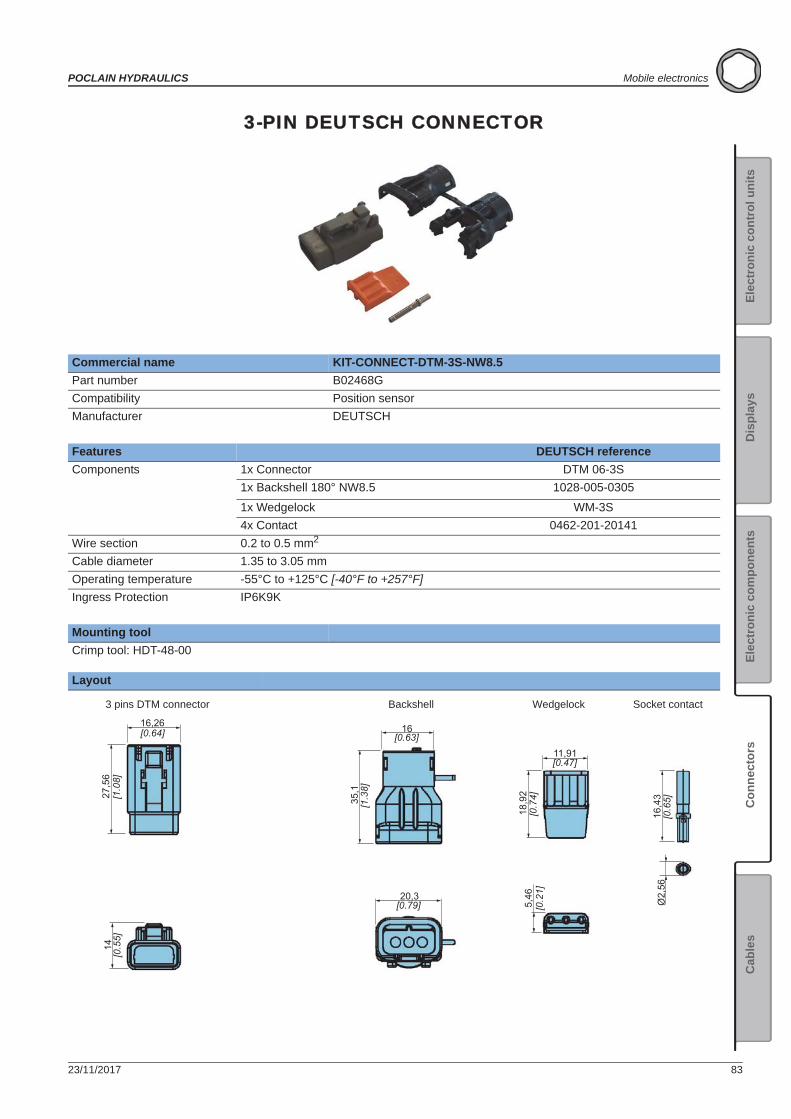
23/11/2017 83
POCLAIN HYDRAULICS Mobile electronics
Elec
tron
ic c
ontr
ol u
nits
Elec
tron
ic c
ompo
nent
sC
onne
ctor
sC
able
sD
ispl
ays
3-PIN DEUTSCH CONNECTOR
Commercial name KIT-CONNECT-DTM-3S-NW8.5Part number B02468GCompatibility Position sensorManufacturer DEUTSCH
Features DEUTSCH referenceComponents 1x Connector DTM 06-3S
1x Backshell 180° NW8.5 1028-005-0305
1x Wedgelock WM-3S4x Contact 0462-201-20141
Wire section 0.2 to 0.5 mm2
Cable diameter 1.35 to 3.05 mmOperating temperature -55°C to +125°C [-40°F to +257°F]Ingress Protection IP6K9K
Mounting toolCrimp tool: HDT-48-00
Layout
14[0
.55]
16,26[0.64]
27,5
6[1
.08]
16[0.63]
[1.3
8]35
,1
20,3[0.79]
11,91[0.47]
18,9
2[0
.74]
5,46
[0.2
1]
16,4
3[0
.65]
Ø2,
56
3 pins DTM connector Wedgelock Socket contactBackshell
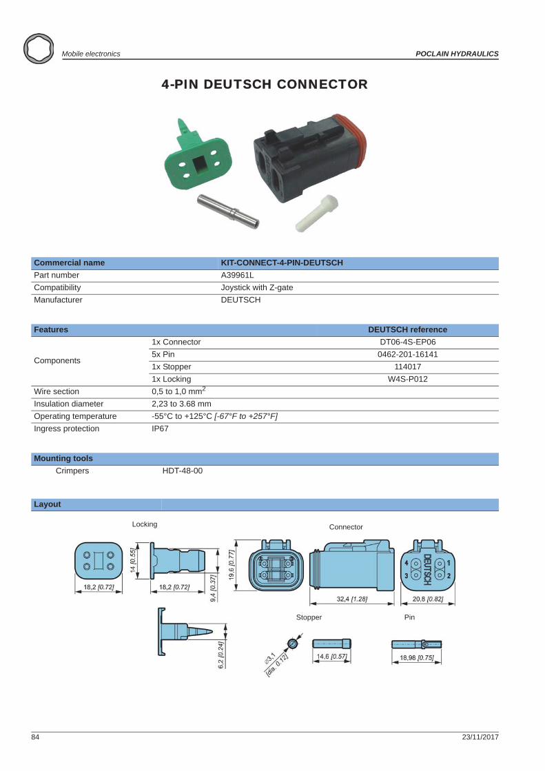
84 23/11/2017
Mobile electronics POCLAIN HYDRAULICS
4-PIN DEUTSCH CONNECTOR
Commercial name KIT-CONNECT-4-PIN-DEUTSCHPart number A39961LCompatibility Joystick with Z-gateManufacturer DEUTSCH
Features DEUTSCH reference
Components
1x Connector DT06-4S-EP065x Pin 0462-201-161411x Stopper 1140171x Locking W4S-P012
Wire section 0,5 to 1,0 mm2
Insulation diameter 2,23 to 3.68 mmOperating temperature -55°C to +125°C [-67°F to +257°F]Ingress protection IP67
Mounting toolsCrimpers HDT-48-00
Layout
ConnectorLocking
Stopper Pin
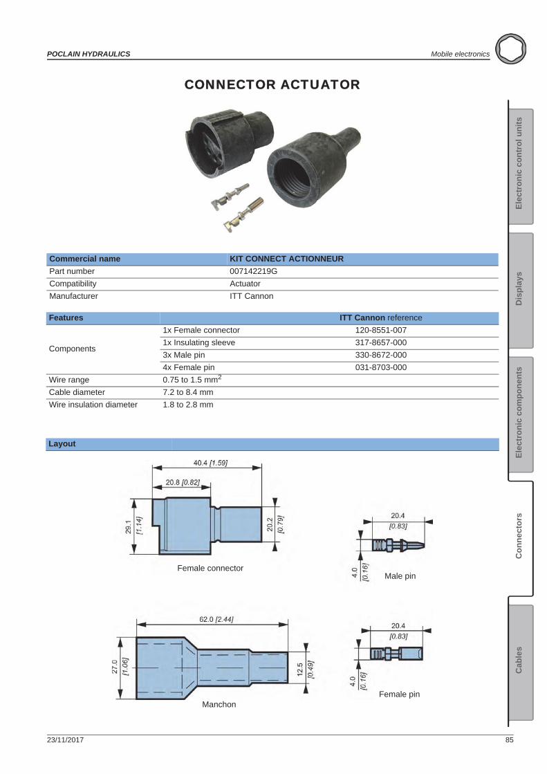
23/11/2017 85
POCLAIN HYDRAULICS Mobile electronics
Elec
tron
ic c
ontr
ol u
nits
Elec
tron
ic c
ompo
nent
sC
onne
ctor
sC
able
sD
ispl
ays
CONNECTOR ACTUATOR
Commercial name KIT CONNECT ACTIONNEURPart number 007142219GCompatibility ActuatorManufacturer ITT Cannon
Features ITT Cannon reference
Components
1x Female connector 120-8551-0071x Insulating sleeve 317-8657-0003x Male pin 330-8672-0004x Female pin 031-8703-000
Wire range 0.75 to 1.5 mm2
Cable diameter 7.2 to 8.4 mmWire insulation diameter 1.8 to 2.8 mm
Layout
Female connector
Manchon
Male pin
Female pin
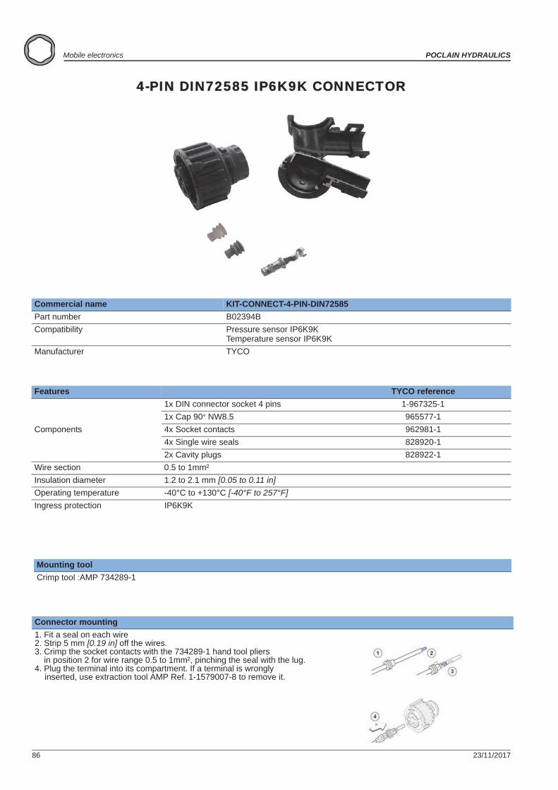
86 23/11/2017
Mobile electronics POCLAIN HYDRAULICS
4-PIN DIN72585 IP6K9K CONNECTOR
Commercial name KIT-CONNECT-4-PIN-DIN72585Part number B02394BCompatibility Pressure sensor IP6K9K
Temperature sensor IP6K9KManufacturer TYCO
Features TYCO reference
Components
1x DIN connector socket 4 pins 1-967325-11x Cap 90° NW8.5 965577-14x Socket contacts 962981-14x Single wire seals 828920-12x Cavity plugs 828922-1
Wire section 0.5 to 1mm² Insulation diameter 1.2 to 2.1 mm [0.05 to 0.11 in]Operating temperature -40°C to +130°C [-40°F to 257°F]Ingress protection IP6K9K
Mounting toolCrimp tool :AMP 734289-1
Connector mounting1. Fit a seal on each wire2. Strip 5 mm [0.19 in] off the wires.3. Crimp the socket contacts with the 734289-1 hand tool pliers
in position 2 for wire range 0.5 to 1mm², pinching the seal with the lug.4. Plug the terminal into its compartment. If a terminal is wrongly
inserted, use extraction tool AMP Ref. 1-1579007-8 to remove it.
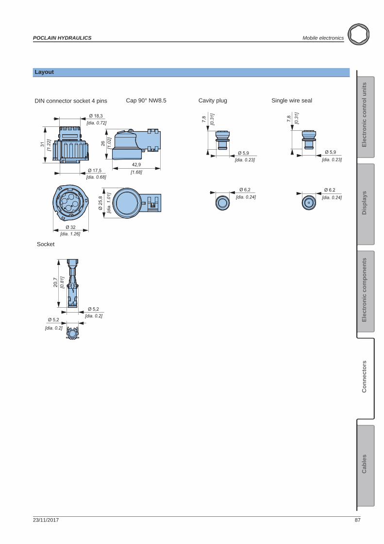
23/11/2017 87
POCLAIN HYDRAULICS Mobile electronics
Elec
tron
ic c
ontr
ol u
nits
Elec
tron
ic c
ompo
nent
sC
onne
ctor
sC
able
sD
ispl
ays
42,9[1.68]
Ø 32
Ø 17,5
Ø 18,3
Ø 5,2
Ø 5,2
20,7
31
Ø 2
5,8
26
7,8
Ø 5,9
Ø 6.2
[dia. 0.72]
[dia. 0.68]
[dia. 1.26]
[dia. 0.2]
[1.2
2]
[dia. 0.2]
[dia. 0.24]
[0.3
1]
[1.0
2][d
ia. 1
.01]
[dia. 0.23]
7,8
Ø 5,9
[0.3
1]
[dia. 0.23]
Ø 6,2[dia. 0.24]
[0.8
1]
Layout
DIN connector socket 4 pins Cap 90° NW8.5 Cavity plug Single wire seal
Socket
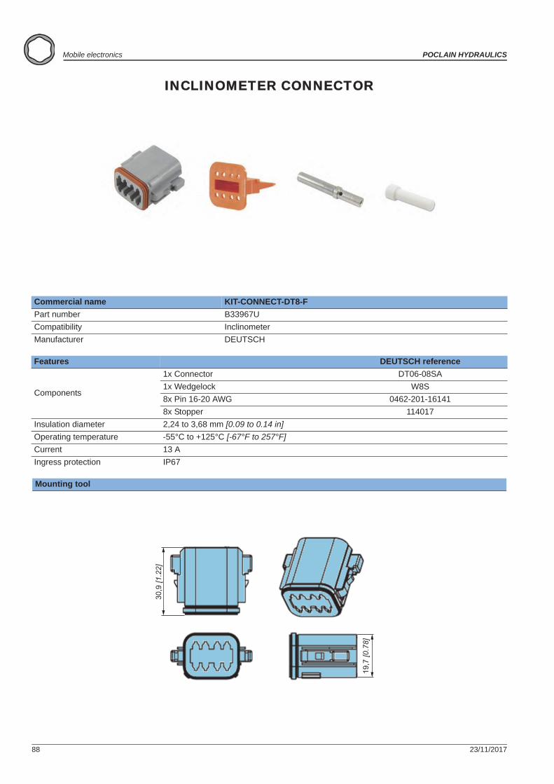
88 23/11/2017
Mobile electronics POCLAIN HYDRAULICS
INCLINOMETER CONNECTOR
Commercial name KIT-CONNECT-DT8-FPart number B33967UCompatibility InclinometerManufacturer DEUTSCH
Features DEUTSCH reference
Components
1x Connector DT06-08SA1x Wedgelock W8S8x Pin 16-20 AWG 0462-201-16141 8x Stopper 114017
Insulation diameter 2,24 to 3,68 mm [0.09 to 0.14 in]Operating temperature -55°C to +125°C [-67°F to 257°F]Current 13 AIngress protection IP67
Mounting tool
30,9
[1.2
2]
19,7
[0.7
8]
23/11/2017 89
POCLAIN HYDRAULICS Mobile electronics
Elec
tron
ic c
ontr
ol u
nits
Elec
tron
ic c
ompo
nent
sC
onne
ctor
sC
able
sD
ispl
ays
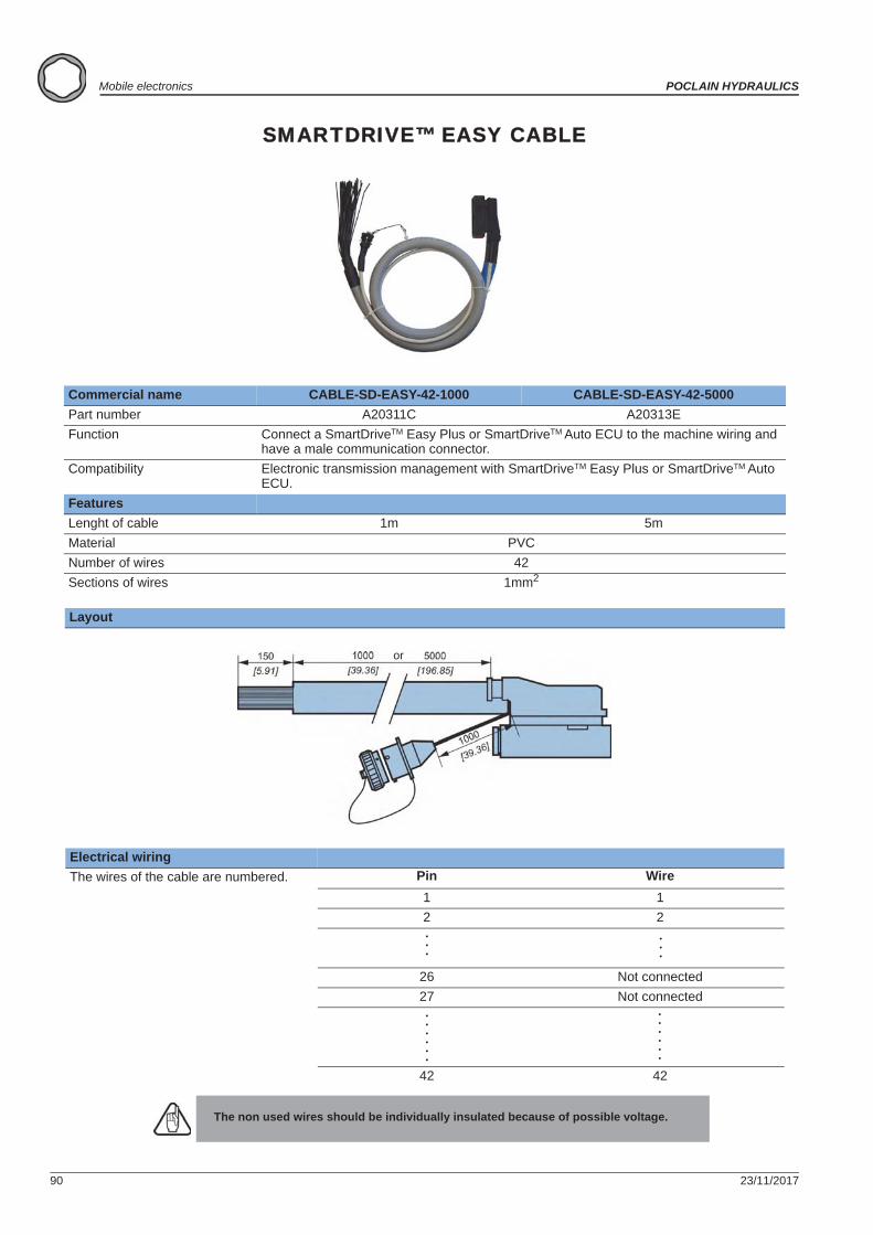
90 23/11/2017
Mobile electronics POCLAIN HYDRAULICS
SMARTDRIVE™ EASY CABLE
Commercial name CABLE-SD-EASY-42-1000 CABLE-SD-EASY-42-5000Part number A20311C A20313EFunction Connect a SmartDriveTM Easy Plus or SmartDriveTM Auto ECU to the machine wiring and
have a male communication connector.Compatibility Electronic transmission management with SmartDriveTM Easy Plus or SmartDriveTM Auto
ECU.FeaturesLenght of cable 1m 5mMaterial PVCNumber of wires 42Sections of wires 1mm2
Layout
Electrical wiringThe wires of the cable are numbered. Pin Wire
1 12 2
26 Not connected27 Not connected
42 42
The non used wires should be individually insulated because of possible voltage.
or
Cables
. . .
. . .
. . .
. . .
. . .
. . .
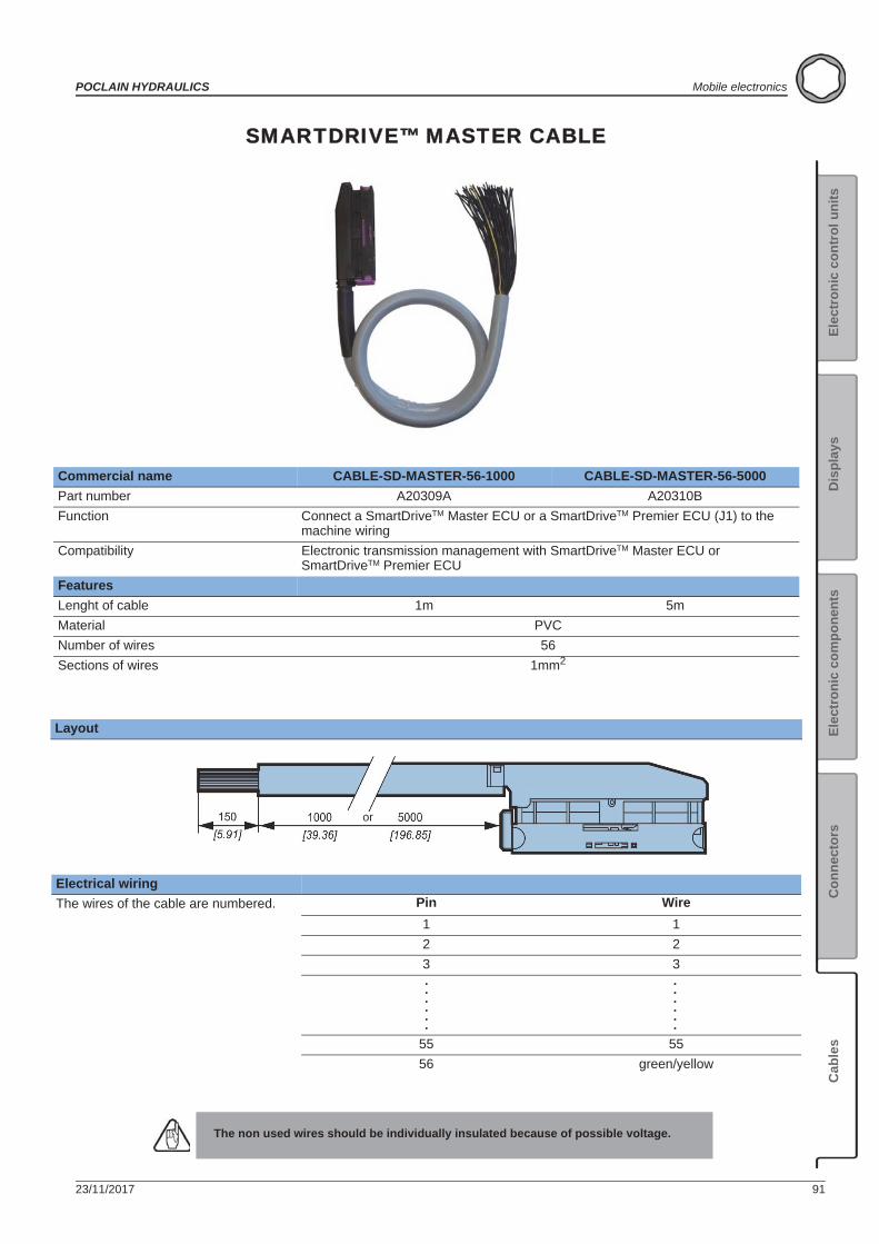
23/11/2017 91
POCLAIN HYDRAULICS Mobile electronics
Elec
tron
ic c
ontr
ol u
nits
Elec
tron
ic c
ompo
nent
sC
onne
ctor
sC
able
sD
ispl
ays
SMARTDRIVE™ MASTER CABLE
Commercial name CABLE-SD-MASTER-56-1000 CABLE-SD-MASTER-56-5000Part number A20309A A20310BFunction Connect a SmartDriveTM Master ECU or a SmartDriveTM Premier ECU (J1) to the
machine wiringCompatibility Electronic transmission management with SmartDriveTM Master ECU or
SmartDriveTM Premier ECUFeaturesLenght of cable 1m 5mMaterial PVCNumber of wires 56Sections of wires 1mm2
Layout
Electrical wiringThe wires of the cable are numbered. Pin Wire
1 12 23 3
55 5556 green/yellow
The non used wires should be individually insulated because of possible voltage.
or
. . .
. . .
. . .
. . .
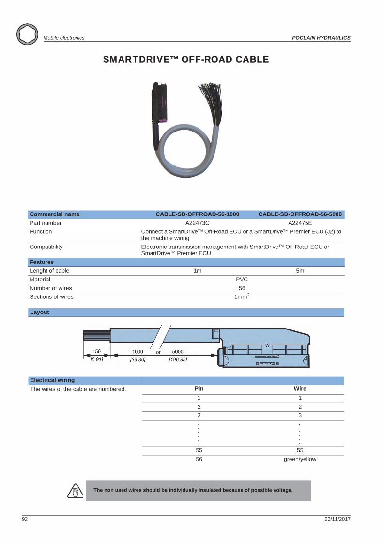
92 23/11/2017
Mobile electronics POCLAIN HYDRAULICS
SMARTDRIVE™ OFF-ROAD CABLE
Commercial name CABLE-SD-OFFROAD-56-1000 CABLE-SD-OFFROAD-56-5000Part number A22473C A22475EFunction Connect a SmartDriveTM Off-Road ECU or a SmartDriveTM Premier ECU (J2) to
the machine wiringCompatibility Electronic transmission management with SmartDriveTM Off-Road ECU or
SmartDriveTM Premier ECUFeaturesLenght of cable 1m 5mMaterial PVCNumber of wires 56Sections of wires 1mm2
Layout
Electrical wiringThe wires of the cable are numbered. Pin Wire
1 12 23 3
55 5556 green/yellow
The non used wires should be individually insulated because of possible voltage.
or
. . .
. . .
. . .
. . .
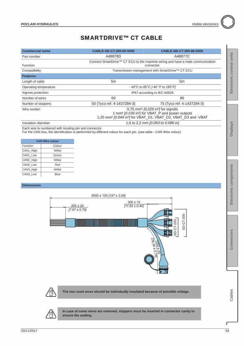
23/11/2017 93
POCLAIN HYDRAULICS Mobile electronics
Elec
tron
ic c
ontr
ol u
nits
Elec
tron
ic c
ompo
nent
sC
onne
ctor
sC
able
sD
ispl
ays
SMARTDRIVE™ CT CABLE
Commercial name CABLE-SD-CT-200-60-5000 CABLE-SD-CT-300-86-5000Part number A48878D A48877C
FunctionConnect SmartDrive™ CT ECU to the machine wiring and have a male communication
connector.Compatibility Transmission management with SmartDrive™ CT ECU
FeaturesLength of cable 5m 5mOperating temperature - 40°C to 85°C [-40 °F to 185°F]
Ingress protection IP67 according to IEC 60529Number of wires 60 86Number of stoppers 50 (Tyco ref: 4-1437284-3) 75 (Tyco ref: 4-1437284-3)Wire section 0,75 mm² [0.029 in²] for signals
1 mm² [0.039 in²] for VBAT_P and power outputs1,25 mm² [0.049 in²] for VBAT_D1, VBAT_D2, VBAT_D3 and -VBAT
Insulation diameter 1,6 to 2,2 mm [0.063 to 0.086 in]Each wire is numbered with locating pin and connector.For the CAN bus, the identification is performed by different colour for each pin. (see table - CAN Wire colour)
Dimensions
The non used wires should be individually insulated because of possible voltage.
In case of some wires are removed, stoppers must be inserted in connector cavity to ensure the sealing.
200 ± 20[7.87 ± 0.79]
5000 ± 100 [197 ± 3.94]
300 ± 10[11.82 ± 0.40]
1000 ± 20
[39.36 ± 0.79]
SD
-CT-
300
SD
-CT-
200
CAN Wire colourFunction ColourCAN1_High WhiteCAN1_Low GreenCAN2_High WhiteCAN2_Low RedCAN3_High WhiteCAN3_Low Blue
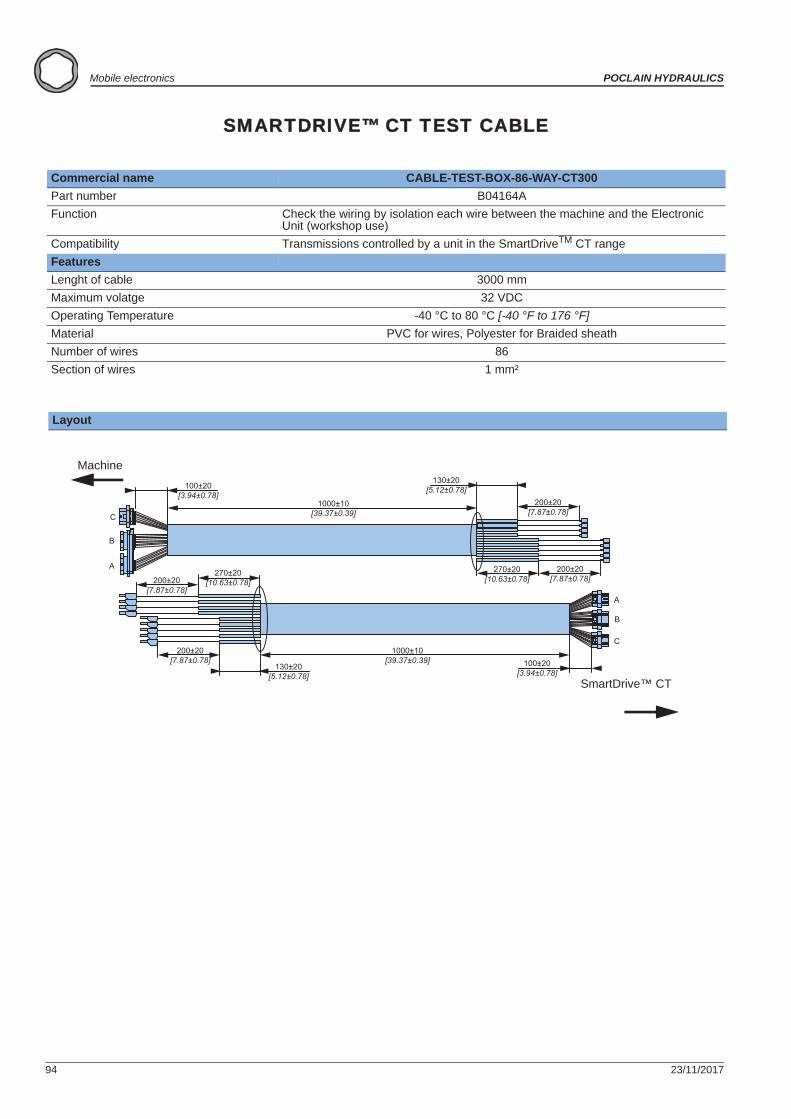
94 23/11/2017
Mobile electronics POCLAIN HYDRAULICS
SMARTDRIVE™ CT TEST CABLE
Commercial name CABLE-TEST-BOX-86-WAY-CT300Part number B04164AFunction Check the wiring by isolation each wire between the machine and the Electronic
Unit (workshop use)Compatibility Transmissions controlled by a unit in the SmartDriveTM CT rangeFeaturesLenght of cable 3000 mmMaximum volatge 32 VDCOperating Temperature -40 °C to 80 °C [-40 °F to 176 °F]Material PVC for wires, Polyester for Braided sheathNumber of wires 86Section of wires 1 mm²
Layout
B
A
C
C
B
A
100±20[3.94±0.78]
1000±10[39.37±0.39]
130±20[5.12±0.78]
200±20[7.87±0.78]
200±20[7.87±0.78]
270±20[10.63±0.78]200±20
[7.87±0.78]
270±20[10.63±0.78]
200±20[7.87±0.78]
130±20[5.12±0.78]
1000±10[39.37±0.39] 100±20
[3.94±0.78]
Machine
SmartDrive™ CT
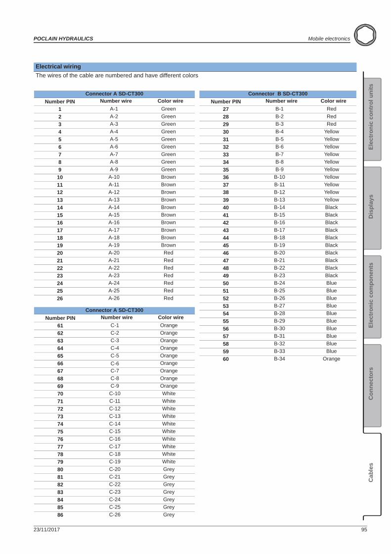
23/11/2017 95
POCLAIN HYDRAULICS Mobile electronics
Elec
tron
ic c
ontr
ol u
nits
Elec
tron
ic c
ompo
nent
sC
onne
ctor
sC
able
sD
ispl
ays
Connector A SD-CT300Number PIN Number wire Color wire
1 A-1 Green2 A-2 Green3 A-3 Green4 A-4 Green5 A-5 Green6 A-6 Green7 A-7 Green8 A-8 Green9 A-9 Green
10 A-10 Brown11 A-11 Brown12 A-12 Brown13 A-13 Brown14 A-14 Brown15 A-15 Brown16 A-16 Brown17 A-17 Brown18 A-18 Brown19 A-19 Brown20 A-20 Red21 A-21 Red22 A-22 Red23 A-23 Red24 A-24 Red25 A-25 Red26 A-26 Red
Connector B SD-CT300Number PIN Number wire Color wire
27 B-1 Red28 B-2 Red29 B-3 Red30 B-4 Yellow31 B-5 Yellow32 B-6 Yellow33 B-7 Yellow34 B-8 Yellow35 B-9 Yellow36 B-10 Yellow37 B-11 Yellow38 B-12 Yellow39 B-13 Yellow40 B-14 Black41 B-15 Black42 B-16 Black43 B-17 Black44 B-18 Black45 B-19 Black46 B-20 Black47 B-21 Black48 B-22 Black49 B-23 Black50 B-24 Blue51 B-25 Blue52 B-26 Blue53 B-27 Blue54 B-28 Blue55 B-29 Blue56 B-30 Blue57 B-31 Blue58 B-32 Blue59 B-33 Blue60 B-34 Orange
Connector A SD-CT300Number PIN Number wire Color wire
61 C-1 Orange62 C-2 Orange63 C-3 Orange64 C-4 Orange65 C-5 Orange66 C-6 Orange67 C-7 Orange68 C-8 Orange69 C-9 Orange70 C-10 White71 C-11 White72 C-12 White73 C-13 White74 C-14 White75 C-15 White76 C-16 White77 C-17 White78 C-18 White79 C-19 White80 C-20 Grey81 C-21 Grey82 C-22 Grey83 C-23 Grey84 C-24 Grey85 C-25 Grey86 C-26 Grey
Electrical wiringThe wires of the cable are numbered and have different colors
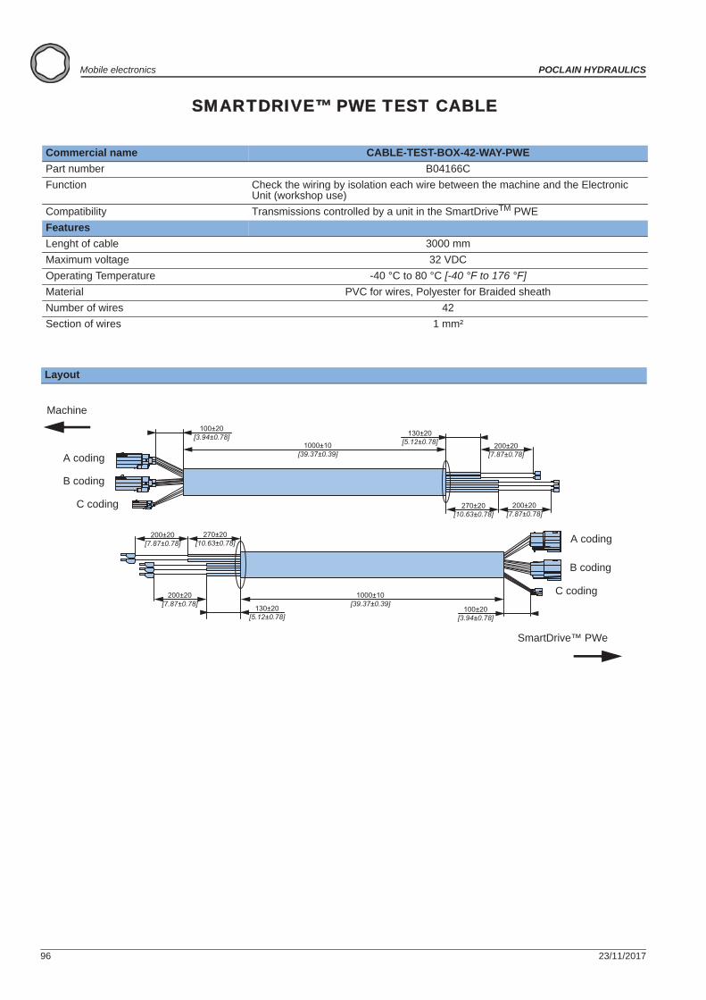
96 23/11/2017
Mobile electronics POCLAIN HYDRAULICS
SMARTDRIVE™ PWE TEST CABLE
Commercial name CABLE-TEST-BOX-42-WAY-PWEPart number B04166CFunction Check the wiring by isolation each wire between the machine and the Electronic
Unit (workshop use)Compatibility Transmissions controlled by a unit in the SmartDriveTM PWEFeaturesLenght of cable 3000 mmMaximum voltage 32 VDCOperating Temperature -40 °C to 80 °C [-40 °F to 176 °F]Material PVC for wires, Polyester for Braided sheathNumber of wires 42Section of wires 1 mm²
Layout
100±20[3.94±0.78]
1000±10[39.37±0.39]
130±20[5.12±0.78] 200±20
[7.87±0.78]
200±20[7.87±0.78]
270±20[10.63±0.78]
200±20[7.87±0.78]
270±20[10.63±0.78]
200±20[7.87±0.78] 130±20
[5.12±0.78]
1000±10[39.37±0.39]
100±20[3.94±0.78]
A coding
B coding
C coding
A coding
B coding
C coding
Machine
SmartDrive™ PWe
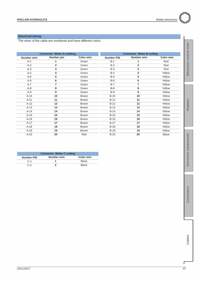
23/11/2017 97
POCLAIN HYDRAULICS Mobile electronics
Elec
tron
ic c
ontr
ol u
nits
Elec
tron
ic c
ompo
nent
sC
onne
ctor
sC
able
sD
ispl
ays
Connector Molex A coddingNumber wire Number pin Color wire
A-1 1 GreenA-2 2 GreenA-3 3 GreenA-4 4 GreenA-5 5 GreenA-6 6 GreenA-7 7 GreenA-8 8 GreenA-9 9 Green
A-10 10 BrownA-11 11 BrownA-12 12 BrownA-13 13 BrownA-14 14 BrownA-15 15 BrownA-16 16 BrownA-17 17 BrownA-18 18 BrownA-19 19 BrownA-20 20 Red
Connector Molex B codingNumber PIN Number wire Color wire
B-1 1 RedB-2 2 RedB-3 3 RedB-4 4 YellowB-5 5 YellowB-6 6 YellowB-7 7 YellowB-8 8 YellowB-9 9 Yellow
B-10 10 YellowB-11 11 YellowB-12 12 YellowB-13 13 YellowB-14 14 YellowB-15 15 YellowB-16 16 YellowB-17 17 YellowB-18 18 YellowB-19 19 YellowB-20 20 Black
Connector Molex C codingNumber PIN Number wire Color wire
C-1 1 BlackC-2 2 Black
Electrical wiringThe wires of the cable are numbered and have different colors
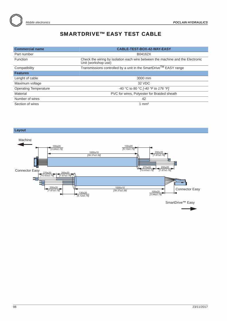
98 23/11/2017
Mobile electronics POCLAIN HYDRAULICS
SMARTDRIVE™ EASY TEST CABLE
Commercial name CABLE-TEST-BOX-42-WAY-EASYPart number B04162XFunction Check the wiring by isolation each wire between the machine and the Electronic
Unit (workshop use)Compatibility Transmissions controlled by a unit in the SmartDriveTM EASY rangeFeaturesLenght of cable 3000 mmMaximum voltage 32 VDCOperating Temperature -40 °C to 80 °C [-40 °F to 176 °F]Material PVC for wires, Polyester for Braided sheathNumber of wires 42Section of wires 1 mm²
Layout
100±20[3.94±0.78]
1000±10[39.37±0.39]
130±20[5.12±0.78]
200±20[7.87±0.78]
200±20[7.87±0.78]
270±20[10.63±0.78]
200±20[7.87±0.78]
270±20[10.63±0.78]
200±20[7.87±0.78]
130±20[5.12±0.78]
1000±10[39.37±0.39] 100±20
[3.94±0.78]
Machine
SmartDrive™ Easy
Connector Easy
Connector Easy
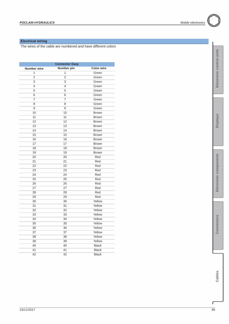
23/11/2017 99
POCLAIN HYDRAULICS Mobile electronics
Elec
tron
ic c
ontr
ol u
nits
Elec
tron
ic c
ompo
nent
sC
onne
ctor
sC
able
sD
ispl
ays
Connector EasyNumber wire Number pin Color wire
1 1 Green2 2 Green3 3 Green4 4 Green5 5 Green6 6 Green7 7 Green8 8 Green9 9 Green
10 10 Brown11 11 Brown12 12 Brown13 13 Brown14 14 Brown15 15 Brown16 16 Brown17 17 Brown18 18 Brown19 19 Brown20 20 Red21 21 Red22 22 Red23 23 Red24 24 Red25 25 Red26 26 Red27 27 Red28 28 Red29 29 Red30 30 Yellow31 31 Yellow32 32 Yellow33 33 Yellow34 34 Yellow35 35 Yellow36 36 Yellow37 37 Yellow38 38 Yellow39 39 Yellow40 40 Black41 41 Black42 42 Black
Electrical wiringThe wires of the cable are numbered and have different colors
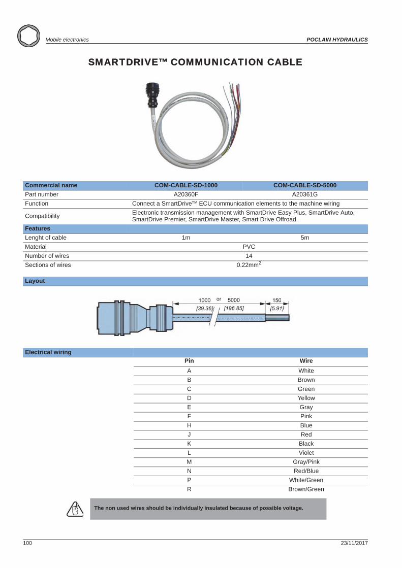
100 23/11/2017
Mobile electronics POCLAIN HYDRAULICS
SMARTDRIVE™ COMMUNICATION CABLE
Commercial name COM-CABLE-SD-1000 COM-CABLE-SD-5000Part number A20360F A20361GFunction Connect a SmartDriveTM ECU communication elements to the machine wiring
Compatibility Electronic transmission management with SmartDrive Easy Plus, SmartDrive Auto, SmartDrive Premier, SmartDrive Master, Smart Drive Offroad.
FeaturesLenght of cable 1m 5mMaterial PVCNumber of wires 14Sections of wires 0.22mm2
Layout
Electrical wiringPin WireA WhiteB BrownC GreenD YellowE GrayF PinkH BlueJ RedK BlackL VioletM Gray/PinkN Red/BlueP White/GreenR Brown/Green
The non used wires should be individually insulated because of possible voltage.
or
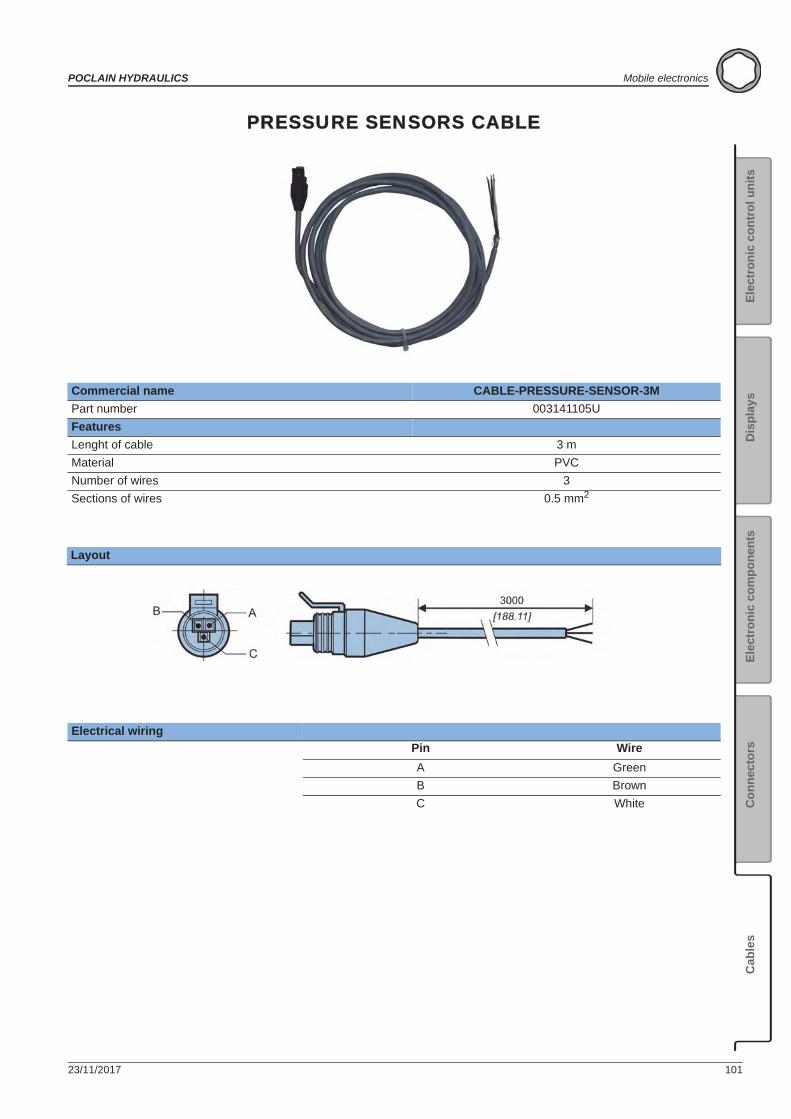
23/11/2017 101
POCLAIN HYDRAULICS Mobile electronics
Elec
tron
ic c
ontr
ol u
nits
Elec
tron
ic c
ompo
nent
sC
onne
ctor
sC
able
sD
ispl
ays
PRESSURE SENSORS CABLE
Commercial name CABLE-PRESSURE-SENSOR-3MPart number 003141105UFeaturesLenght of cable 3 mMaterial PVCNumber of wires 3Sections of wires 0.5 mm2
Layout
Electrical wiringPin WireA GreenB BrownC White
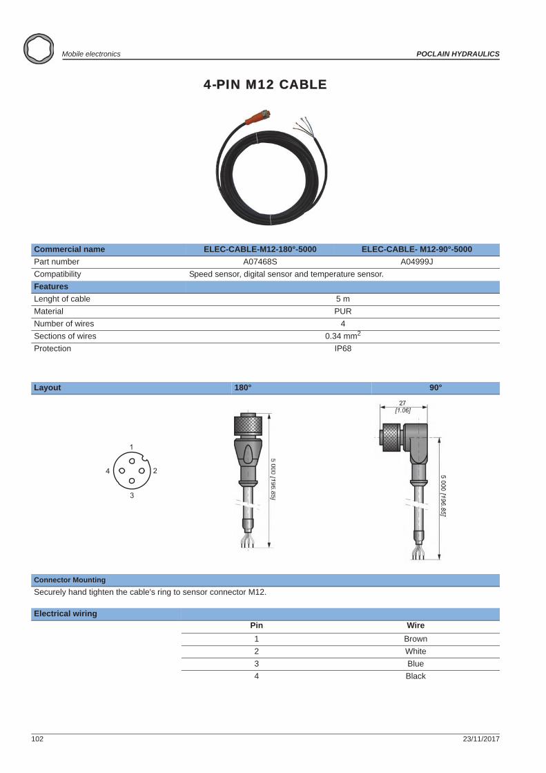
102 23/11/2017
Mobile electronics POCLAIN HYDRAULICS
4-PIN M12 CABLE
Commercial name ELEC-CABLE-M12-180°-5000 ELEC-CABLE- M12-90°-5000Part number A07468S A04999JCompatibility Speed sensor, digital sensor and temperature sensor.FeaturesLenght of cable 5 mMaterial PURNumber of wires 4Sections of wires 0.34 mm2
Protection IP68
Layout 180° 90°
Connector MountingSecurely hand tighten the cable's ring to sensor connector M12.
Electrical wiringPin Wire1 Brown2 White3 Blue4 Black
1
2
3
4
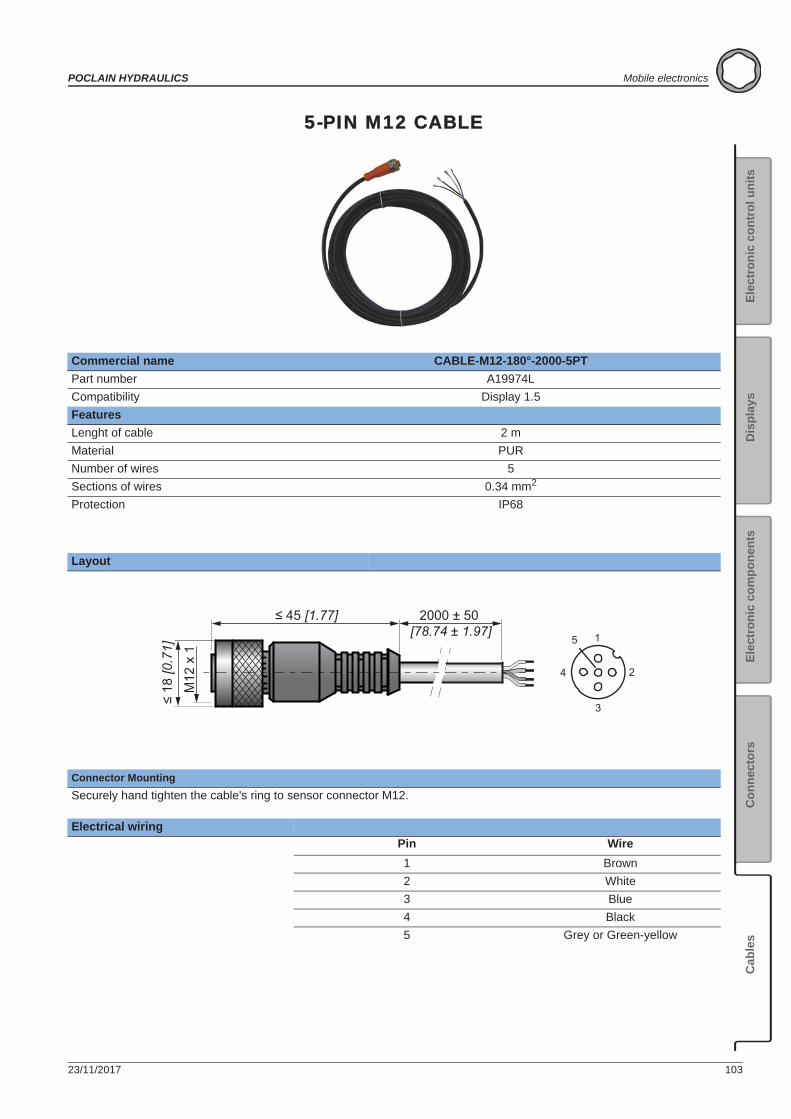
23/11/2017 103
POCLAIN HYDRAULICS Mobile electronics
Elec
tron
ic c
ontr
ol u
nits
Elec
tron
ic c
ompo
nent
sC
onne
ctor
sC
able
sD
ispl
ays
5-PIN M12 CABLE
Commercial name CABLE-M12-180°-2000-5PTPart number A19974LCompatibility Display 1.5FeaturesLenght of cable 2 mMaterial PURNumber of wires 5Sections of wires 0.34 mm2
Protection IP68
Layout
Connector MountingSecurely hand tighten the cable's ring to sensor connector M12.
Electrical wiringPin Wire1 Brown2 White3 Blue4 Black5 Grey or Green-yellow
45 [1.77] 2000 ± 50 [78.74 ± 1.97]
M12
x 1
18
[0.7
1]
1
2
3
4
5
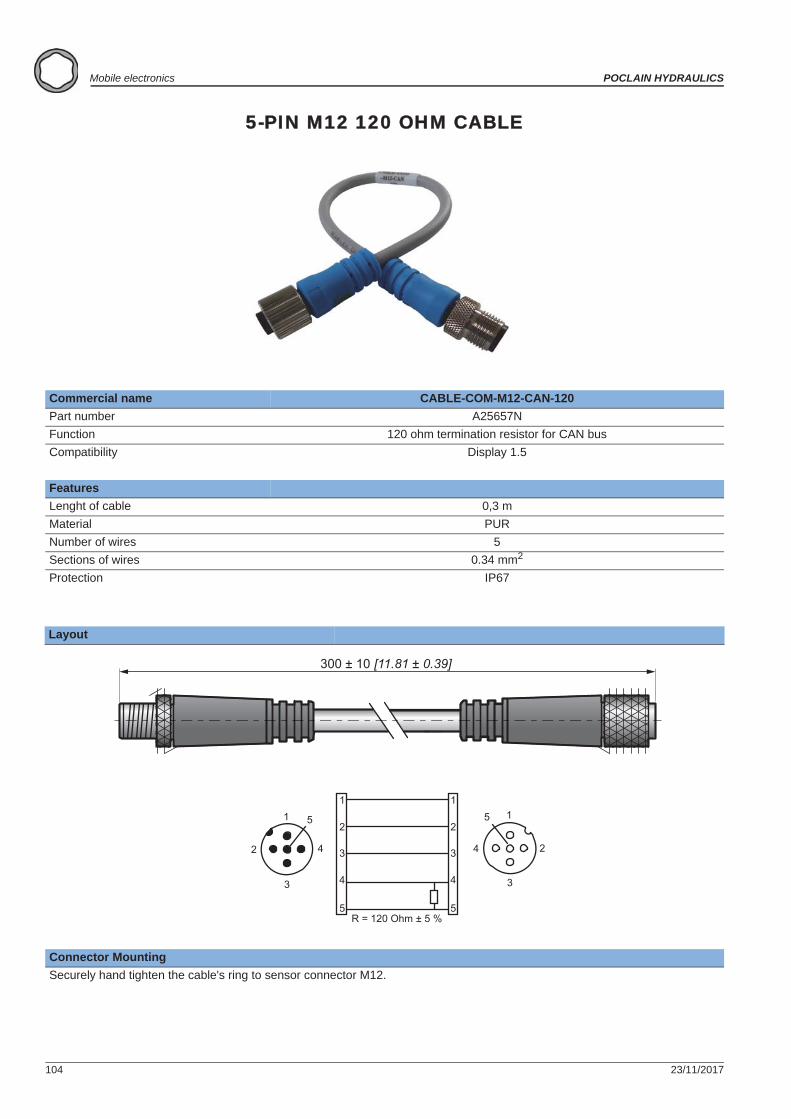
104 23/11/2017
Mobile electronics POCLAIN HYDRAULICS
5-PIN M12 120 OHM CABLE
Commercial name CABLE-COM-M12-CAN-120Part number A25657NFunction 120 ohm termination resistor for CAN busCompatibility Display 1.5
FeaturesLenght of cable 0,3 mMaterial PURNumber of wires 5Sections of wires 0.34 mm2
Protection IP67
Layout
Connector MountingSecurely hand tighten the cable's ring to sensor connector M12.
R = 120 Ohm ± 5 %
300 ± 10 [11.81 ± 0.39]
1
2
3
4
5
1
2
3
4
5
1
2
3
4
51
2
3
4
5
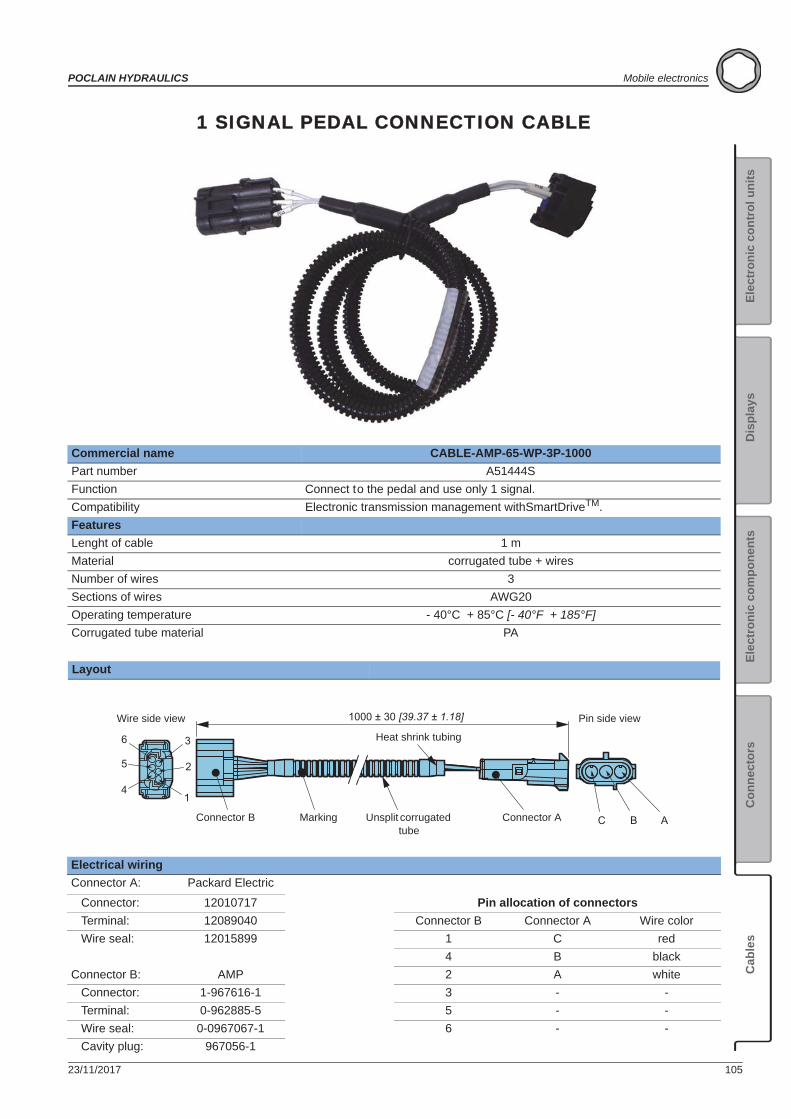
23/11/2017 105
POCLAIN HYDRAULICS Mobile electronics
Elec
tron
ic c
ontr
ol u
nits
Elec
tron
ic c
ompo
nent
sC
onne
ctor
sC
able
sD
ispl
ays
1 SIGNAL PEDAL CONNECTION CABLE
Commercial name CABLE-AMP-65-WP-3P-1000Part number A51444SFunction Connect to the pedal and use only 1 signal.Compatibility Electronic transmission management withSmartDriveTM.FeaturesLenght of cable 1 mMaterial corrugated tube + wiresNumber of wires 3Sections of wires AWG20Operating temperature - 40°C + 85°C [- 40°F + 185°F]Corrugated tube material PA
Layout
Electrical wiringConnector A: Packard Electric
Connector: 12010717 Pin allocation of connectors Terminal: 12089040 Connector B Connector A Wire color Wire seal: 12015899 1 C red
4 B blackConnector B: AMP 2 A white Connector: 1-967616-1 3 - - Terminal: 0-962885-5 5 - - Wire seal: 0-0967067-1 6 - - Cavity plug: 967056-1
1
2
36
5
4
C B A
1000 ± 30 [39.37 ± 1.18]Wire side view Pin side view
Connector B Marking Unsplit corrugated tube
Heat shrink tubing
Connector A
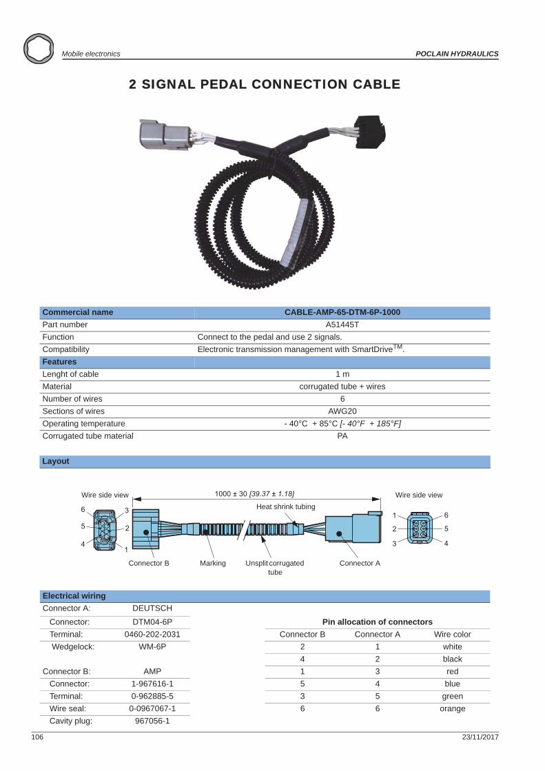
106 23/11/2017
Mobile electronics POCLAIN HYDRAULICS
2 SIGNAL PEDAL CONNECTION CABLE
Commercial name CABLE-AMP-65-DTM-6P-1000Part number A51445TFunction Connect to the pedal and use 2 signals.Compatibility Electronic transmission management with SmartDriveTM.FeaturesLenght of cable 1 mMaterial corrugated tube + wiresNumber of wires 6Sections of wires AWG20Operating temperature - 40°C + 85°C [- 40°F + 185°F]Corrugated tube material PA
Layout
Electrical wiringConnector A: DEUTSCH
Connector: DTM04-6P Pin allocation of connectors Terminal: 0460-202-2031 Connector B Connector A Wire color Wedgelock: WM-6P 2 1 white
4 2 blackConnector B: AMP 1 3 red Connector: 1-967616-1 5 4 blue Terminal: 0-962885-5 3 5 green Wire seal: 0-0967067-1 6 6 orange Cavity plug: 967056-1
1
2
36
5
4
6
1000 ± 30 [39.37 ± 1.18]
4
5
1
3
2
Wire side view
Connector B Marking Unsplit corrugated tube
Heat shrink tubing
Connector A
Wire side view
23/11/2017 107
POCLAIN HYDRAULICS Mobile electronics
Elec
tron
ic c
ontr
ol u
nits
Elec
tron
ic c
ompo
nent
sC
onne
ctor
sC
able
sD
ispl
ays

www.poclain-hydraulics.com
Poclain Hydraulics reserves the right to make any modifications it deems necessary to the products described in this document without prior notification.The information contained in this document must be confirmed by Poclain Hydraulics before any order is submitted.Illustrations are not binding.The Poclain Hydraulics brand is the property of Poclain Hydraulics S.A.
A01888C
A01889D
23/11/17