Mobile Ad Hoc Networks. Acknowledgements Many figures, slides and reference citations are taken...
105
Mobile Ad Hoc Networks
-
date post
22-Dec-2015 -
Category
Documents
-
view
216 -
download
1
Transcript of Mobile Ad Hoc Networks. Acknowledgements Many figures, slides and reference citations are taken...
Mobile Ad Hoc Networks

Acknowledgements
Many figures, slides and reference citations are taken from Nitin Vaidya’s MobiCom’2000 tutorial
Nitin’s tutorial is available online at http://www.cs.tamu.edu/~vaidya/seminars
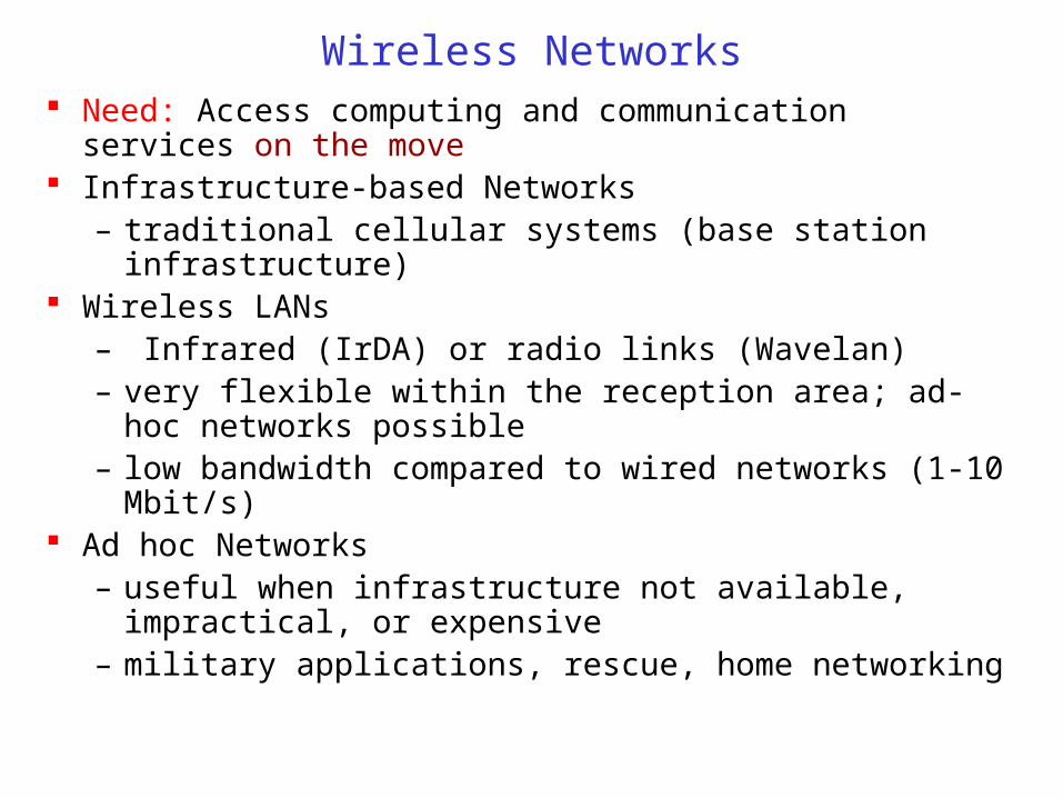
Wireless Networks Need: Access computing and communication services on the
move Infrastructure-based Networks
– traditional cellular systems (base station infrastructure) Wireless LANs
– Infrared (IrDA) or radio links (Wavelan)– very flexible within the reception area; ad-hoc networks
possible– low bandwidth compared to wired networks (1-10 Mbit/s)
Ad hoc Networks– useful when infrastructure not available, impractical, or
expensive– military applications, rescue, home networking
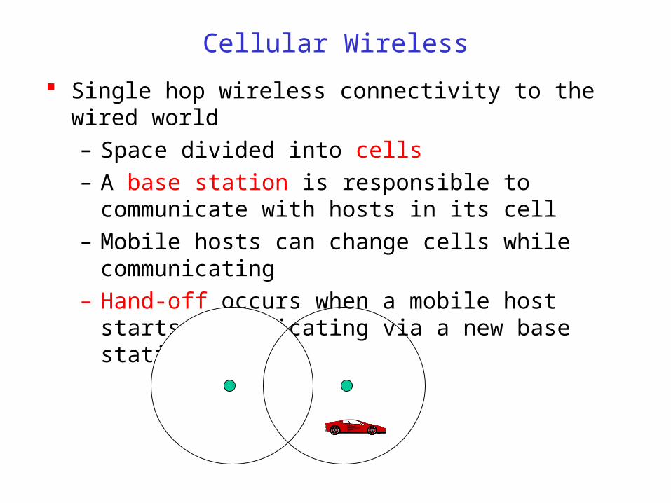
Cellular Wireless
Single hop wireless connectivity to the wired world
– Space divided into cells
– A base station is responsible to communicate with hosts in its cell
– Mobile hosts can change cells while communicating
– Hand-off occurs when a mobile host starts communicating via a new base station

Multi-Hop Wireless
May need to traverse multiple links to reach destination
Mobility causes route changes

Mobile Ad Hoc Networks (MANET)
Host movement frequent Topology change frequent
No cellular infrastructure. Multi-hop wireless links. Data must be routed via intermediate nodes.
A B AB

Why Ad Hoc Networks ? Setting up of fixed access points and backbone infrastructure is
not always viable
– Infrastructure may not be present in a disaster area or war zone
– Infrastructure may not be practical for short-range radios; Bluetooth (range ~ 10m)
Ad hoc networks
– Do not need backbone infrastructure support
– Are easy to deploy
– Useful when infrastructure is absent, destroyed or impractical

Many Applications Personal area networking
– cell phone, laptop, ear phone, wrist watch
Military environments– soldiers, tanks, planes
Civilian environments– taxi cab network
– meeting rooms
– sports stadiums
– boats, small aircraft
Emergency operations– search-and-rescue
– policing and fire fighting
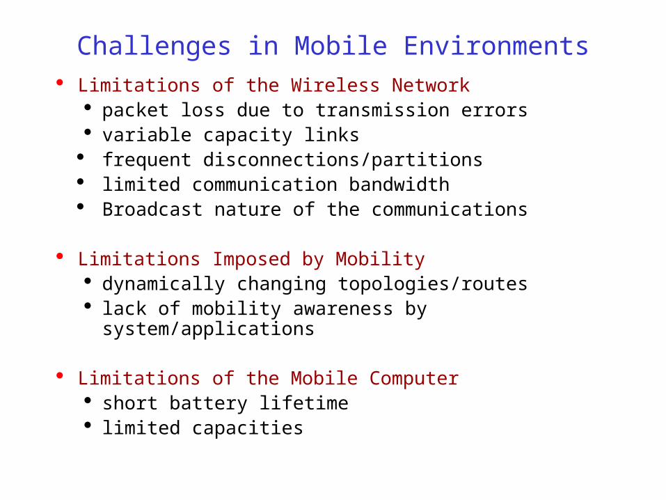
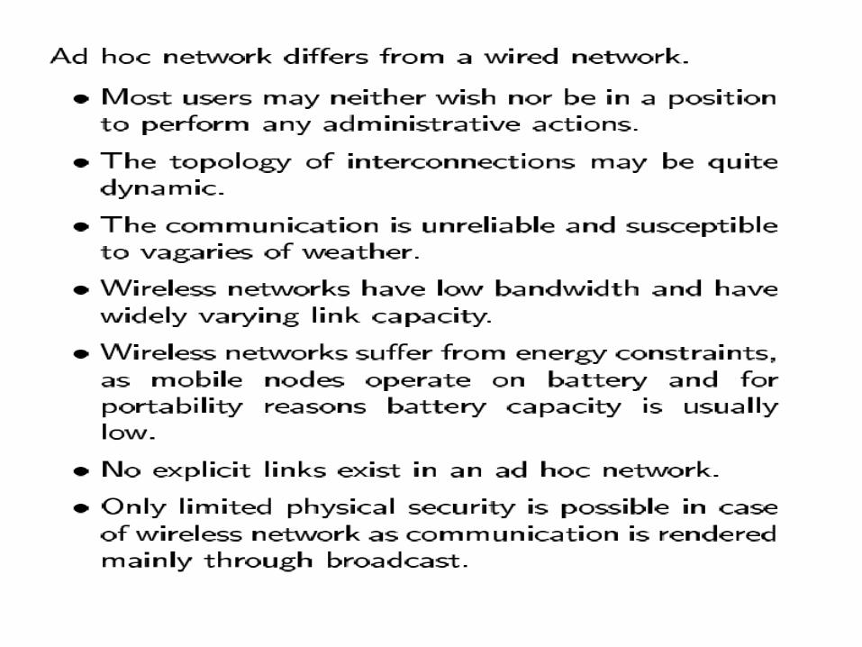
Challenges in Mobile Environments Limitations of the Wireless Network
packet loss due to transmission errors variable capacity links frequent disconnections/partitions limited communication bandwidth Broadcast nature of the communications
Limitations Imposed by Mobility dynamically changing topologies/routes lack of mobility awareness by system/applications
Limitations of the Mobile Computer short battery lifetime limited capacities


Routing Protocols

Traditional Routing
A routing protocol sets up a routing table in routers
A node makes a local choice depending on global topology
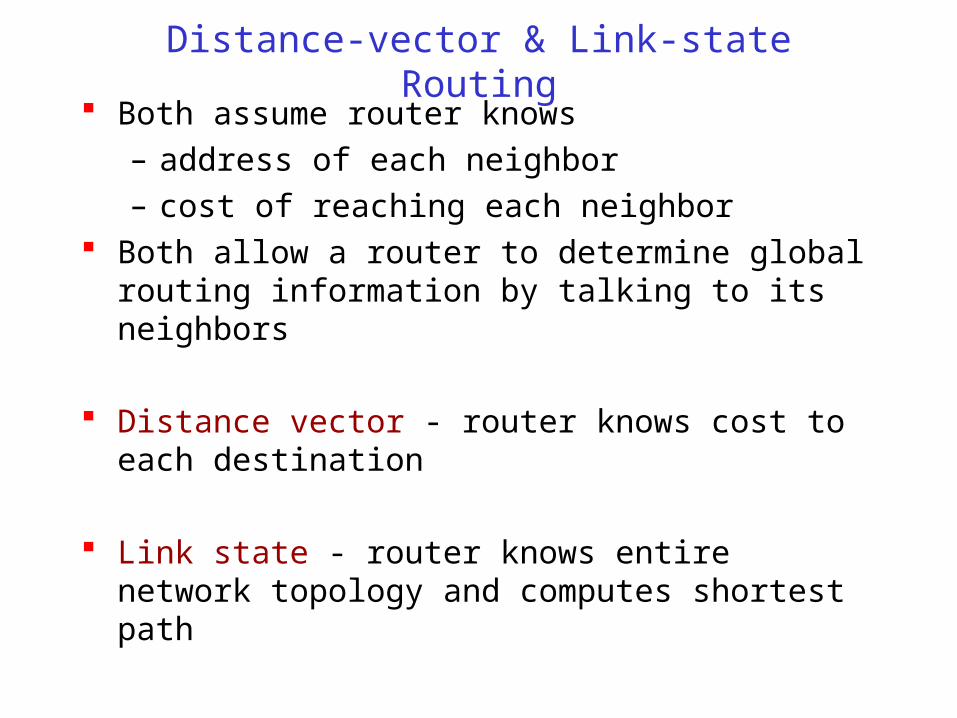
Distance-vector & Link-state Routing Both assume router knows
– address of each neighbor
– cost of reaching each neighbor Both allow a router to determine global routing
information by talking to its neighbors
Distance vector - router knows cost to each destination
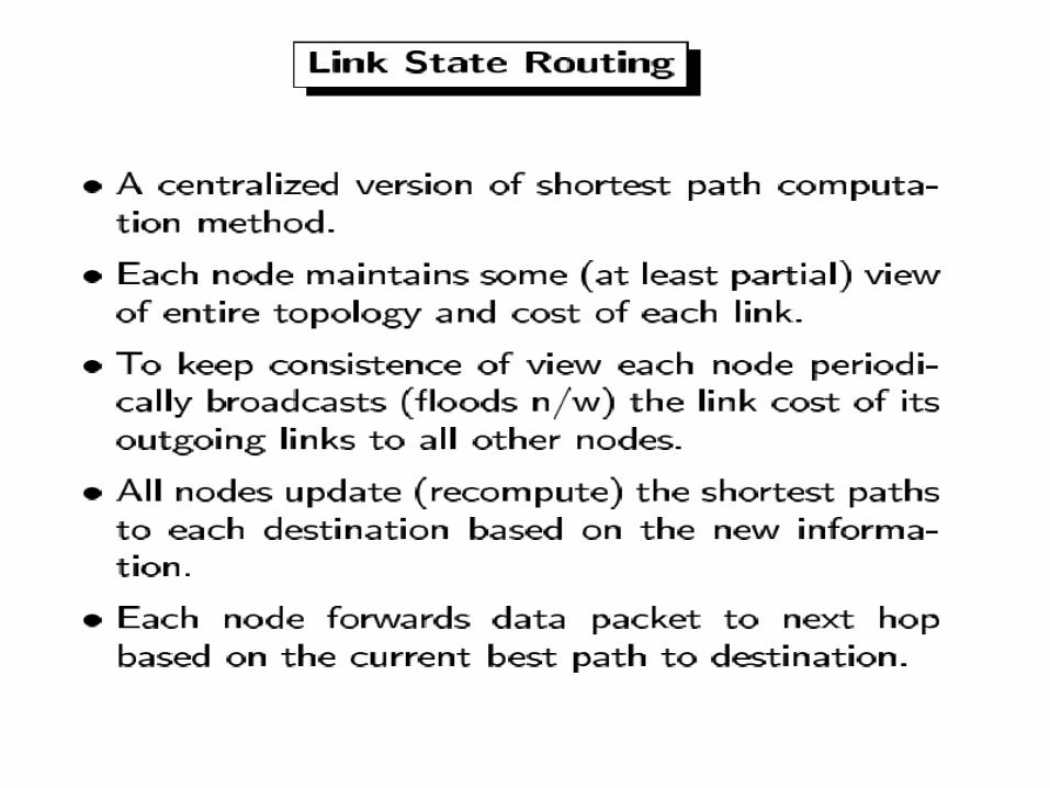
Link state - router knows entire network topology and computes shortest path
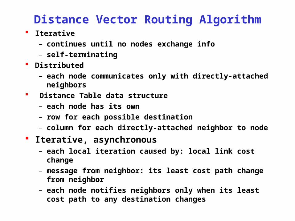
Distance Vector Routing Algorithm Iterative
– continues until no nodes exchange info
– self-terminating Distributed
– each node communicates only with directly-attached neighbors Distance Table data structure
– each node has its own
– row for each possible destination
– column for each directly-attached neighbor to node
Iterative, asynchronous– each local iteration caused by: local link cost change
– message from neighbor: its least cost path change from neighbor
– each node notifies neighbors only when its least cost path to any destination changes

Distance Vector Routing: Example
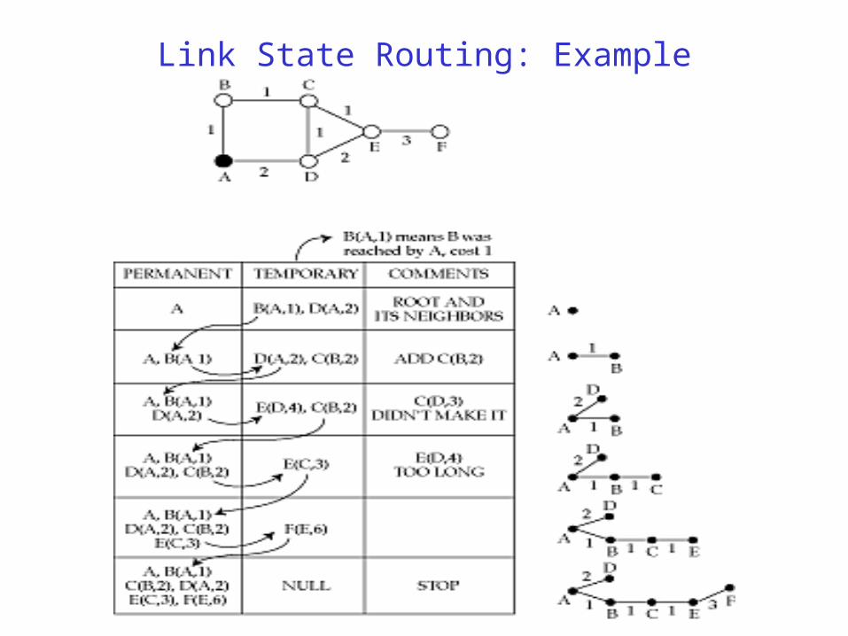
Link State Routing: Example
Routing and Mobility
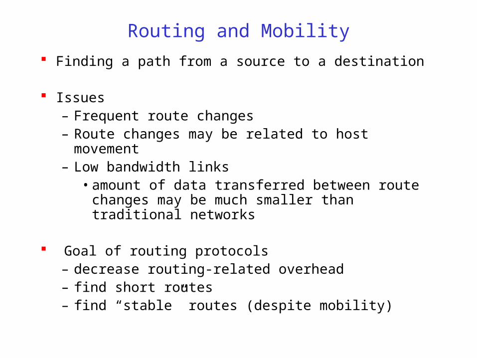
Finding a path from a source to a destination
Issues– Frequent route changes – Route changes may be related to host movement– Low bandwidth links
• amount of data transferred between route changes may be much smaller than traditional networks
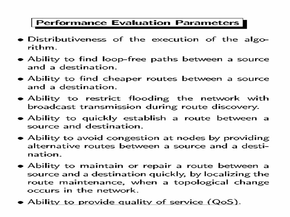
Goal of routing protocols– decrease routing-related overhead– find short routes– find “stable” routes (despite mobility)
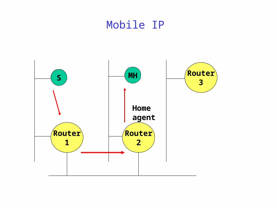
Mobile IP
Router1
Router3
Router2
S MH
Home agent
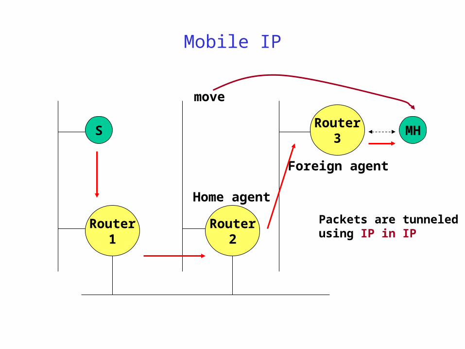
Mobile IP
Router1
Router3
Router2
S MH
Home agent
Foreign agent
move
Packets are tunneledusing IP in IP
Routing in MANET

Unicast Routing Protocols
Many protocols have been proposed
Some specifically invented for MANET Others adapted from protocols for wired networks
No single protocol works well in all environments
– some attempts made to develop adaptive/hybrid protocols
Standardization efforts in IETF
– MANET, MobileIP working groups
– http://www.ietf.org
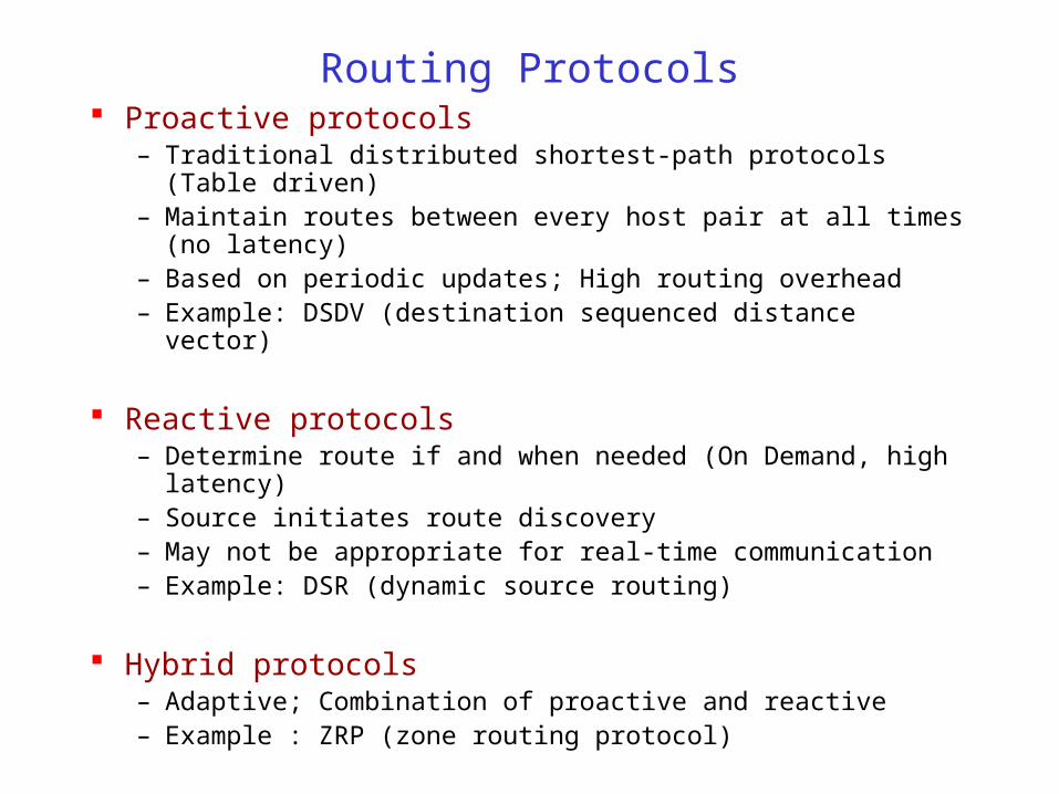
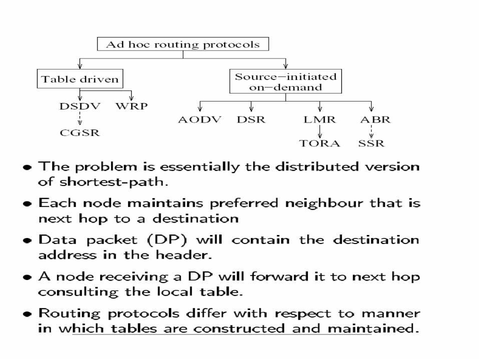
Routing Protocols Proactive protocols
– Traditional distributed shortest-path protocols (Table driven)– Maintain routes between every host pair at all times (no latency)– Based on periodic updates; High routing overhead– Example: DSDV (destination sequenced distance vector)
Reactive protocols– Determine route if and when needed (On Demand, high latency)– Source initiates route discovery– May not be appropriate for real-time communication– Example: DSR (dynamic source routing)
Hybrid protocols– Adaptive; Combination of proactive and reactive– Example : ZRP (zone routing protocol)
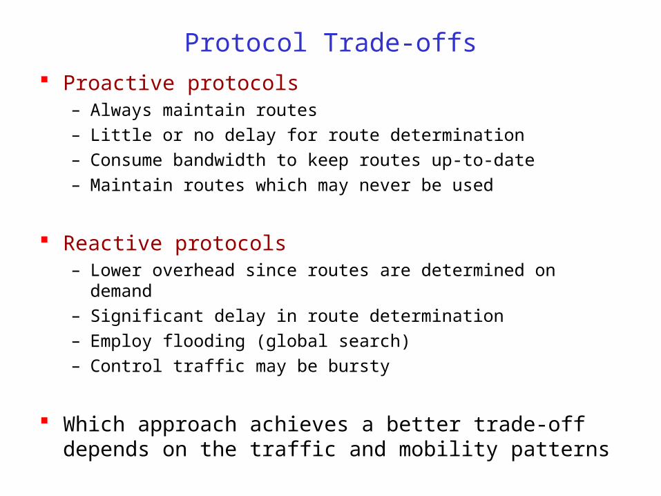
Protocol Trade-offs
Proactive protocols– Always maintain routes
– Little or no delay for route determination
– Consume bandwidth to keep routes up-to-date
– Maintain routes which may never be used
Reactive protocols– Lower overhead since routes are determined on demand
– Significant delay in route determination
– Employ flooding (global search)
– Control traffic may be bursty
Which approach achieves a better trade-off depends on the traffic and mobility patterns
Reactive Routing Protocols
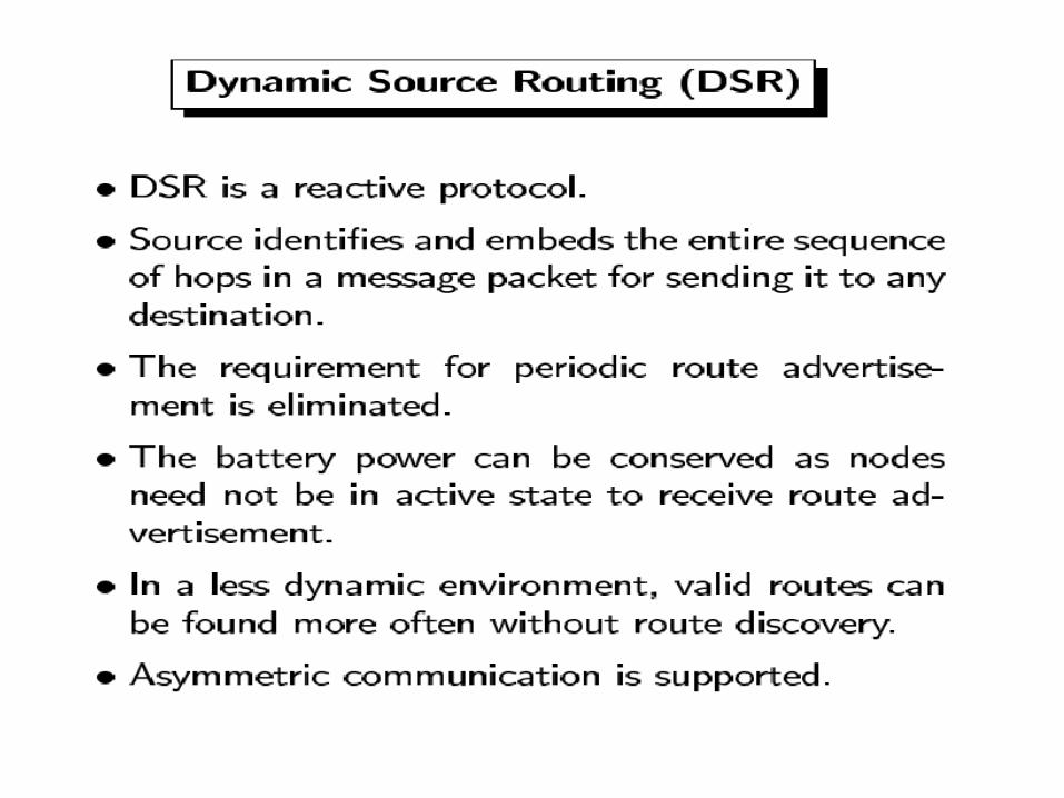

Dynamic Source Routing (DSR) [Johnson96]
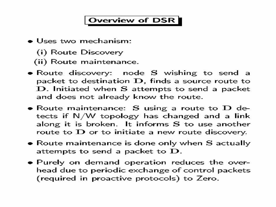
When node S wants to send a packet to node D, but does not know a route to D, node S initiates a route discovery
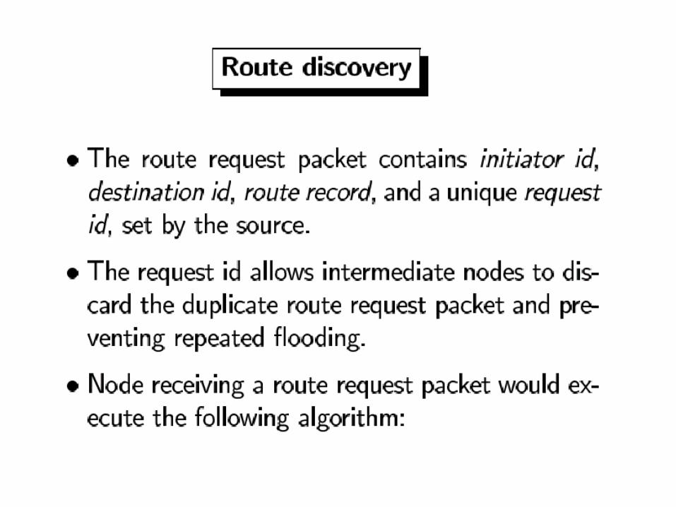
Source node S floods Route Request (RREQ)
Each node appends own identifier when forwarding RREQ


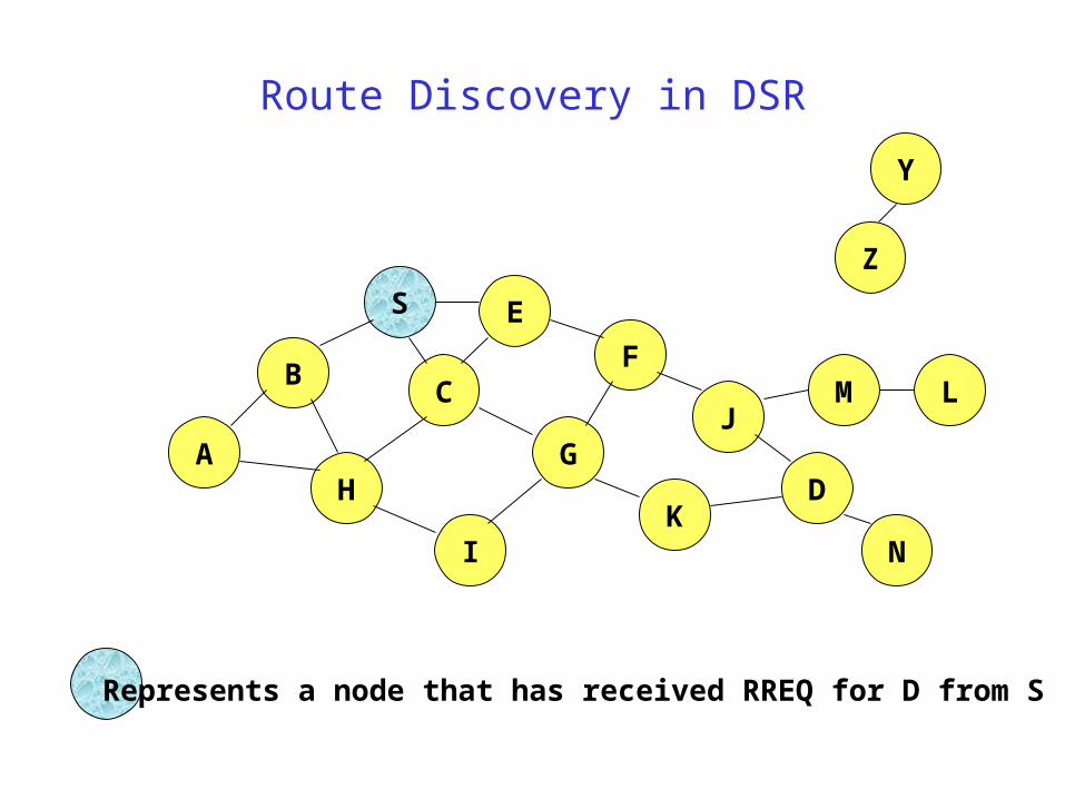
Route Discovery in DSR
B
A
S E
F
H
J
D
C
G
IK
Z
Y
Represents a node that has received RREQ for D from S
M
N
L
Route Discovery in DSR
B
A
S E
F
H
J
D
C
G
IK
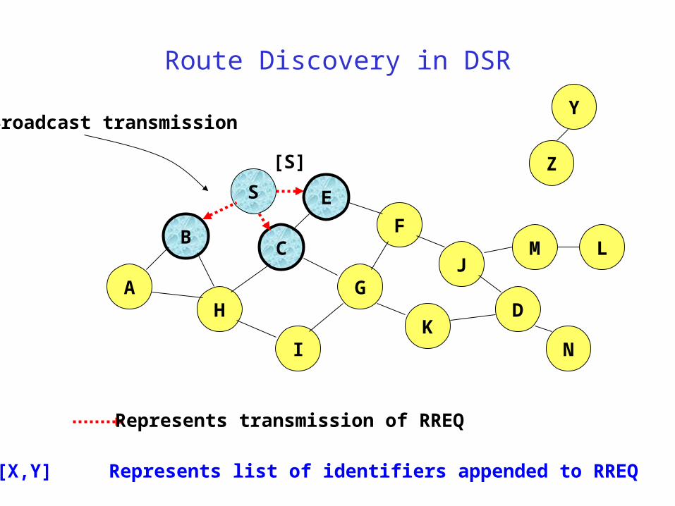
Represents transmission of RREQ
Z
YBroadcast transmission
M
N
L
[S]
[X,Y] Represents list of identifiers appended to RREQ
Route Discovery in DSR
B
A
S E
F
H
J
D
C
G
IK
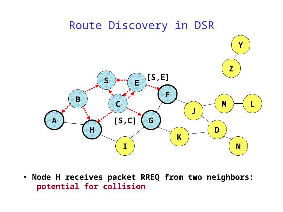
• Node H receives packet RREQ from two neighbors: potential for collision
Z
Y
M
N
L
[S,E]
[S,C]
Route Discovery in DSR
B
A
S E
F
H
J
D
C
G
IK
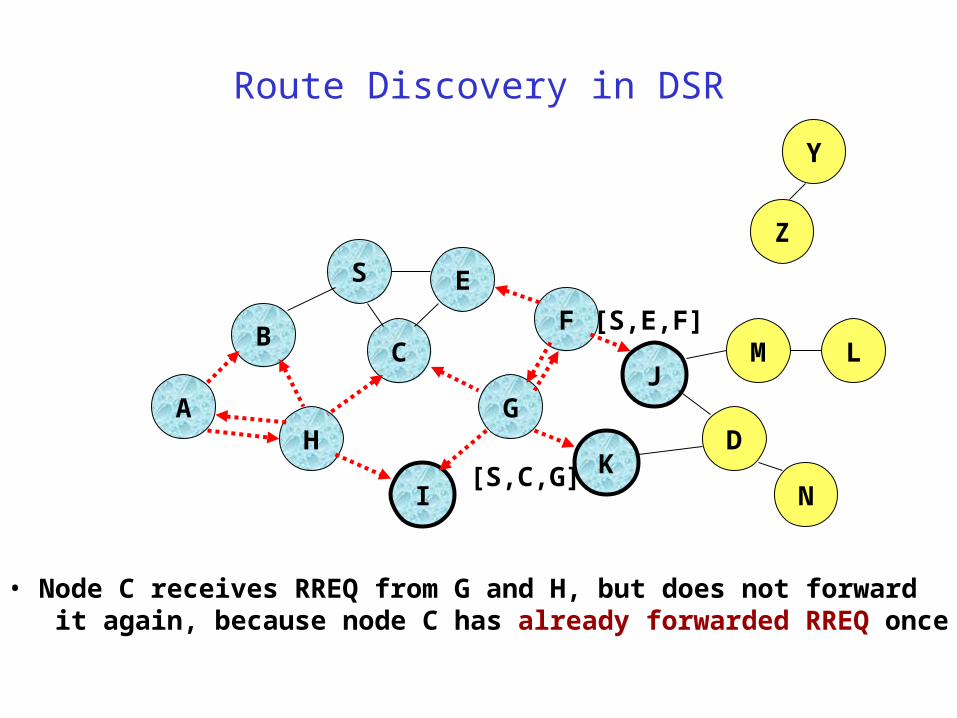
• Node C receives RREQ from G and H, but does not forward it again, because node C has already forwarded RREQ once
Z
Y
M
N
L
[S,C,G]
[S,E,F]
Route Discovery in DSR
B
A
S E
F
H
J
D
C
G
IK
Z
Y
M
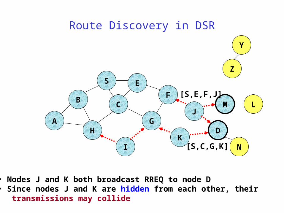
• Nodes J and K both broadcast RREQ to node D• Since nodes J and K are hidden from each other, their transmissions may collide
N
L
[S,C,G,K]
[S,E,F,J]
Route Discovery in DSR
B
A
S E
F
H
J
D
C
G
IK
Z
Y
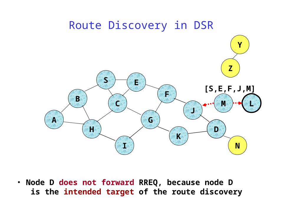
• Node D does not forward RREQ, because node D is the intended target of the route discovery
M
N
L
[S,E,F,J,M]

Route Discovery in DSR
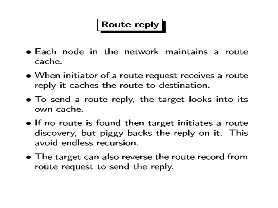
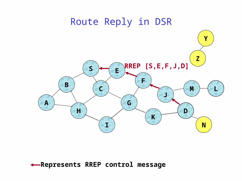
Destination D on receiving the first RREQ, sends a Route Reply (RREP)
RREP is sent on a route obtained by reversing the route appended to received RREQ
RREP includes the route from S to D on which RREQ was received by node D
Route Reply in DSR
B
A
S E
F
H
J
D
C
G
IK
Z
Y
M
N
L
RREP [S,E,F,J,D]
Represents RREP control message
Route Reply in DSR Route Reply can be sent by reversing the route in Route Request
(RREQ) only if links are guaranteed to be bi-directional– To ensure this, RREQ should be forwarded only if it received on a link
that is known to be bi-directional
If unidirectional (asymmetric) links are allowed, then RREP may need a route discovery for S from node D – Unless node D already knows a route to node S
– If a route discovery is initiated by D for a route to S, then the Route Reply is piggybacked on the Route Request from D.
If IEEE 802.11 MAC is used to send data, then links have to be bi-directional (since Ack is used)
Dynamic Source Routing (DSR)
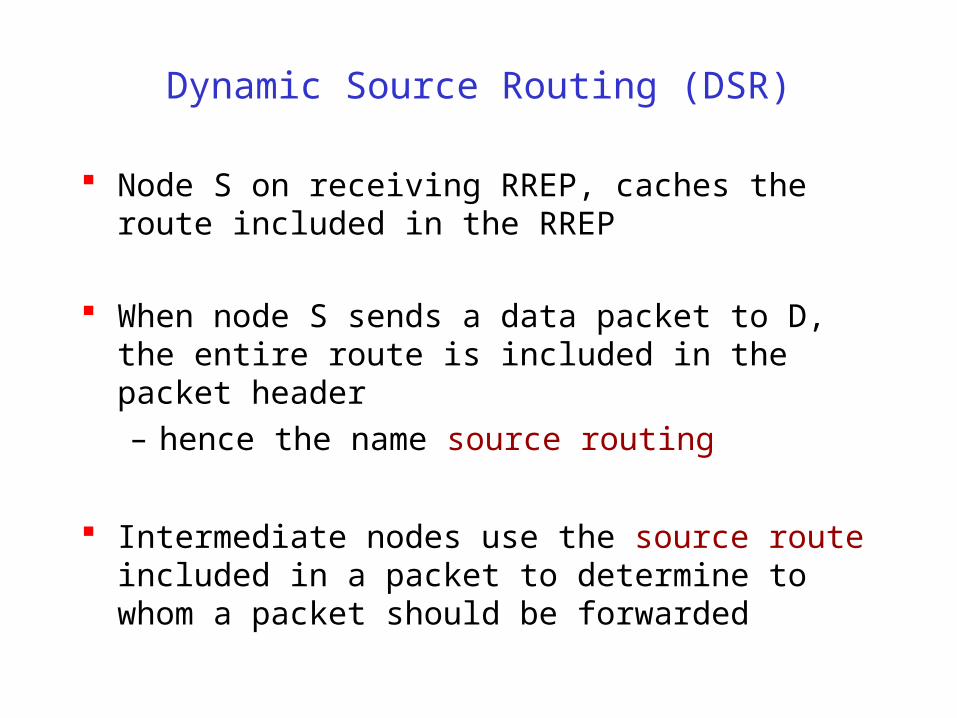
Node S on receiving RREP, caches the route included in the RREP
When node S sends a data packet to D, the entire route is included in the packet header
– hence the name source routing
Intermediate nodes use the source route included in a packet to determine to whom a packet should be forwarded
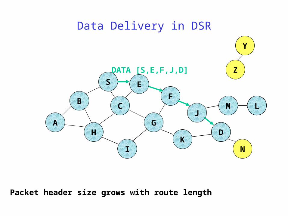
Data Delivery in DSR
B
A
S E
F
H
J
D
C
G
IK
Z
Y
M
N
L
DATA [S,E,F,J,D]
Packet header size grows with route length

DSR Optimization: Route Caching
Each node caches a new route it learns by any means When node S finds route [S,E,F,J,D] to node D, node S
also learns route [S,E,F] to node F When node K receives Route Request [S,C,G] destined for
node, node K learns route [K,G,C,S] to node S When node F forwards Route Reply RREP [S,E,F,J,D],
node F learns route [F,J,D] to node D When node E forwards Data [S,E,F,J,D] it learns route
[E,F,J,D] to node D A node may also learn a route when it overhears Data Problem: Stale caches may increase overheads
Use of Route Caching
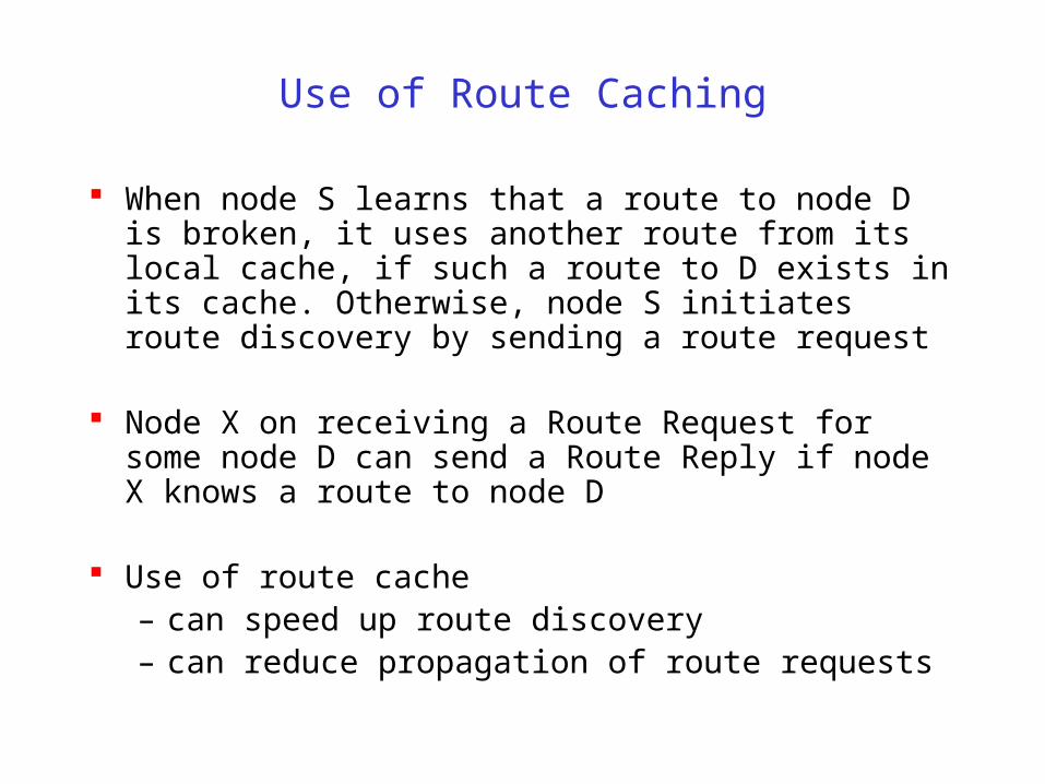
When node S learns that a route to node D is broken, it uses another route from its local cache, if such a route to D exists in its cache. Otherwise, node S initiates route discovery by sending a route request
Node X on receiving a Route Request for some node D can send a Route Reply if node X knows a route to node D
Use of route cache – can speed up route discovery– can reduce propagation of route requests
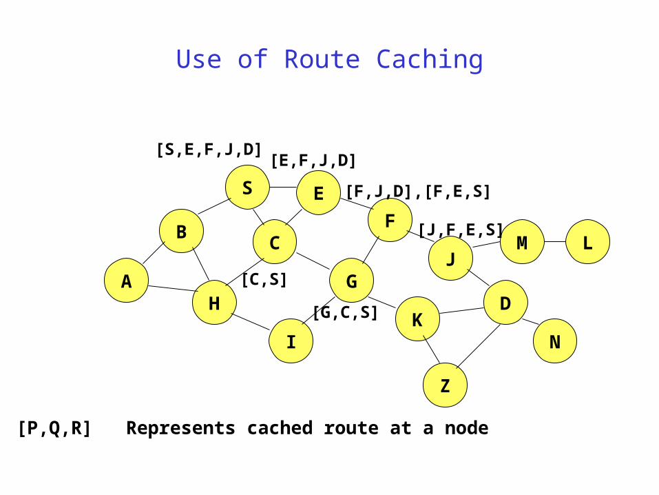
Use of Route Caching
B
A
S E
F
H
J
D
C
G
IK
[P,Q,R] Represents cached route at a node
M
N
L
[S,E,F,J,D][E,F,J,D]
[C,S]
[G,C,S]
[F,J,D],[F,E,S]
[J,F,E,S]
Z
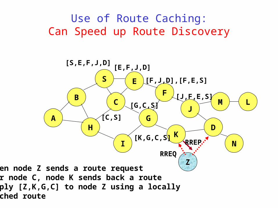
Use of Route Caching:Can Speed up Route Discovery
B
A
S E
F
H
J
D
C
G
IK
Z
M
N
L
[S,E,F,J,D][E,F,J,D]
[C,S]
[G,C,S]
[F,J,D],[F,E,S]
[J,F,E,S]
RREQ
When node Z sends a route requestfor node C, node K sends back a routereply [Z,K,G,C] to node Z using a locallycached route
[K,G,C,S]RREP

Use of Route Caching:Can Reduce Propagation of Route Requests
B
A
S E
F
H
J
D
C
G
IK
Z
Y
M
N
L
[S,E,F,J,D][E,F,J,D]
[C,S]
[G,C,S]
[F,J,D],[F,E,S]
[J,F,E,S]
RREQ
Assume that there is no link between D and Z.Route Reply (RREP) from node K limits flooding of RREQ.
[K,G,C,S]RREP
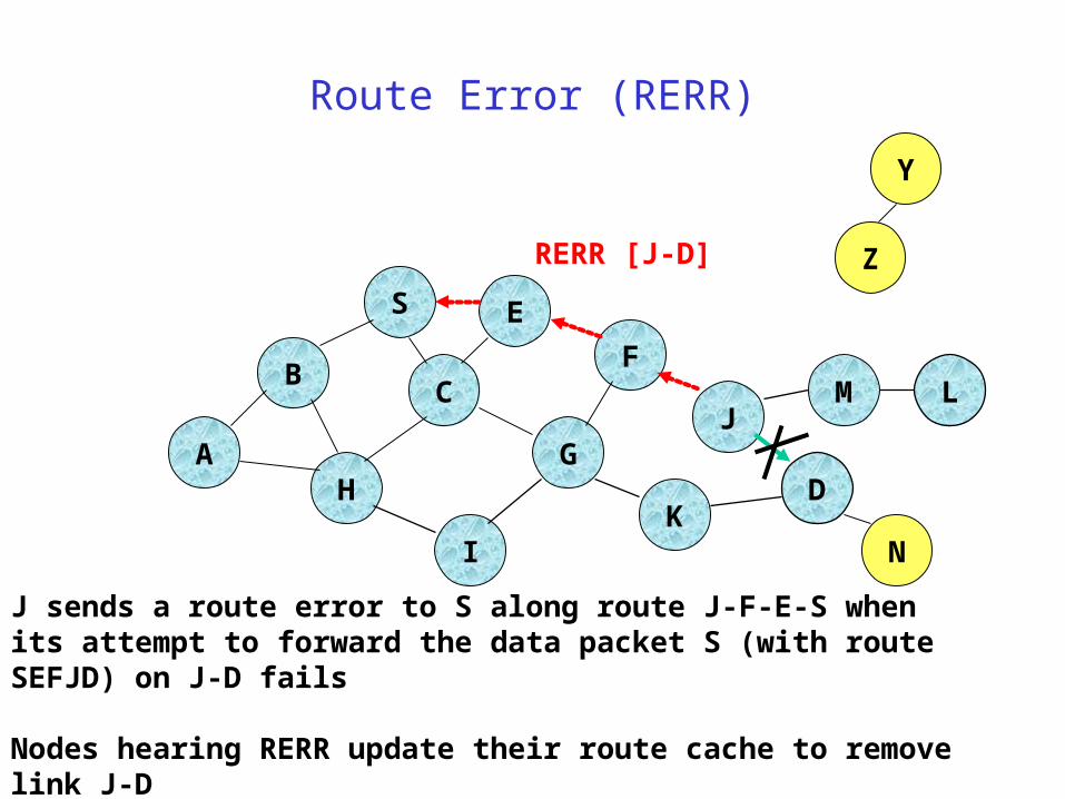
Route Error (RERR)
B
A
S E
F
H
J
D
C
G
IK
Z
Y
M
N
L
RERR [J-D]
J sends a route error to S along route J-F-E-S when its attempt to forward the data packet S (with route SEFJD) on J-D fails
Nodes hearing RERR update their route cache to remove link J-D
Route Caching: Beware!
Stale caches can adversely affect performance
With passage of time and host mobility, cached routes may become invalid
A sender host may try several stale routes (obtained from local cache, or replied from cache by other nodes), before finding a good route
Dynamic Source Routing: Advantages
Routes maintained only between nodes who need to communicate
– reduces overhead of route maintenance
Route caching can further reduce route discovery overhead
A single route discovery may yield many routes to the destination, due to intermediate nodes replying from local caches
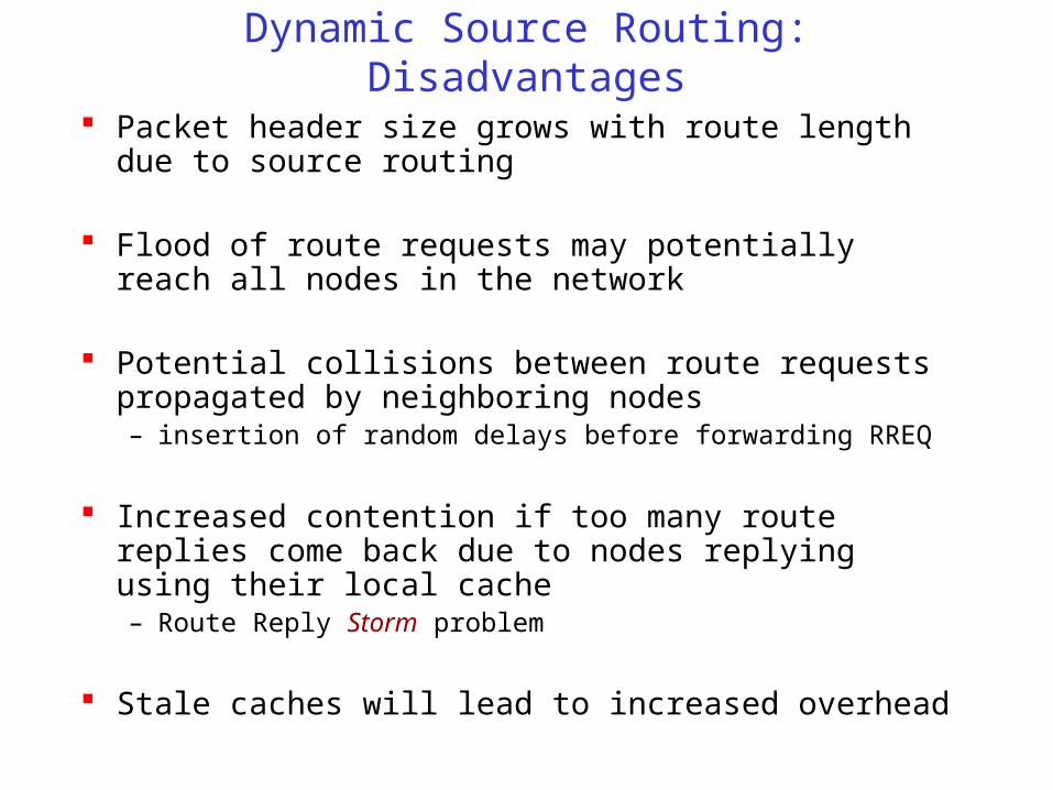
Dynamic Source Routing: Disadvantages
Packet header size grows with route length due to source routing
Flood of route requests may potentially reach all nodes in the network
Potential collisions between route requests propagated by neighboring nodes– insertion of random delays before forwarding RREQ
Increased contention if too many route replies come back due to nodes replying using their local cache– Route Reply Storm problem
Stale caches will lead to increased overhead

Location-Aided Routing (LAR) [Ko98Mobicom]
Exploits location information to limit scope of route request flood– Location information may be obtained using GPS
Expected Zone is determined as a region that is expected to hold the current location of the destination– Expected region determined based on potentially old
location information, and knowledge of the destination’s speed
Route requests limited to a Request Zone that contains the Expected Zone and location of the sender node
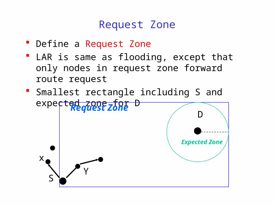
Request Zone
Define a Request Zone LAR is same as flooding, except that only nodes in request
zone forward route request Smallest rectangle including S and expected zone for D
S
Request ZoneD
Expected Zone
x
Y
Location Aided Routing (LAR)
Advantages
– reduces the scope of route request flood
– reduces overhead of route discovery
Disadvantages
– Nodes need to know their physical locations
– Does not take into account possible existence of obstructions for radio transmissions
Ad Hoc On-Demand Distance Vector Routing (AODV) [Perkins99Wmcsa]
DSR includes source routes in packet headers Resulting large headers can sometimes degrade performance
– particularly when data contents of a packet are small
AODV attempts to improve on DSR by maintaining routing tables at the nodes, so that data packets do not have to contain routes
AODV retains the desirable feature of DSR that routes are maintained only between nodes which need to communicate

AODV
Route Requests (RREQ) are forwarded in a manner similar to DSR
When a node re-broadcasts a Route Request, it sets up a reverse path pointing towards the source– AODV assumes symmetric (bi-directional) links
When the intended destination receives a Route Request, it replies by sending a Route Reply (RREP)
Route Reply travels along the reverse path set-up when Route Request is forwarded
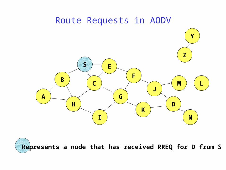
Route Requests in AODV
B
A
S E
F
H
J
D
C
G
IK
Z
Y
Represents a node that has received RREQ for D from S
M
N
L

Route Requests in AODV
B
A
S E
F
H
J
D
C
G
IK
Represents transmission of RREQ
Z
YBroadcast transmission
M
N
L
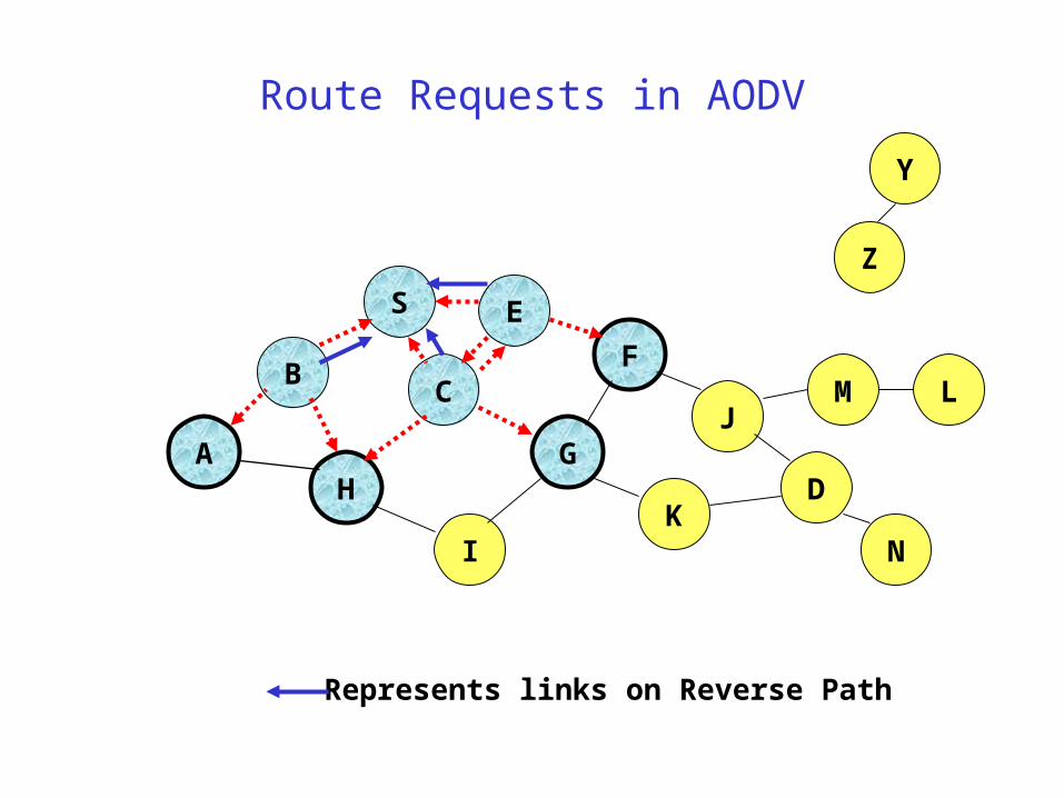
Route Requests in AODV
B
A
S E
F
H
J
D
C
G
IK
Represents links on Reverse Path
Z
Y
M
N
L
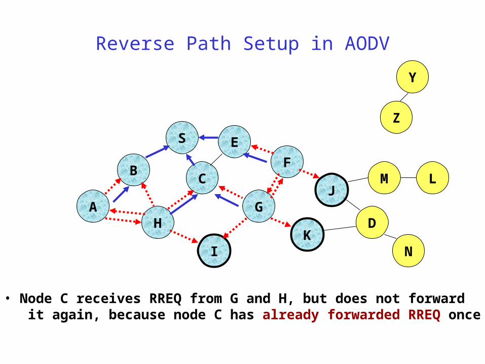
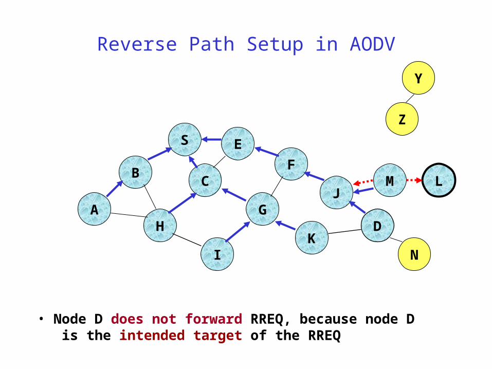
Reverse Path Setup in AODV
B
A
S E
F
H
J
D
C
G
IK
• Node C receives RREQ from G and H, but does not forward it again, because node C has already forwarded RREQ once
Z
Y
M
N
L
Reverse Path Setup in AODV
B
A
S E
F
H
J
D
C
G
IK
Z
Y
M
N
L
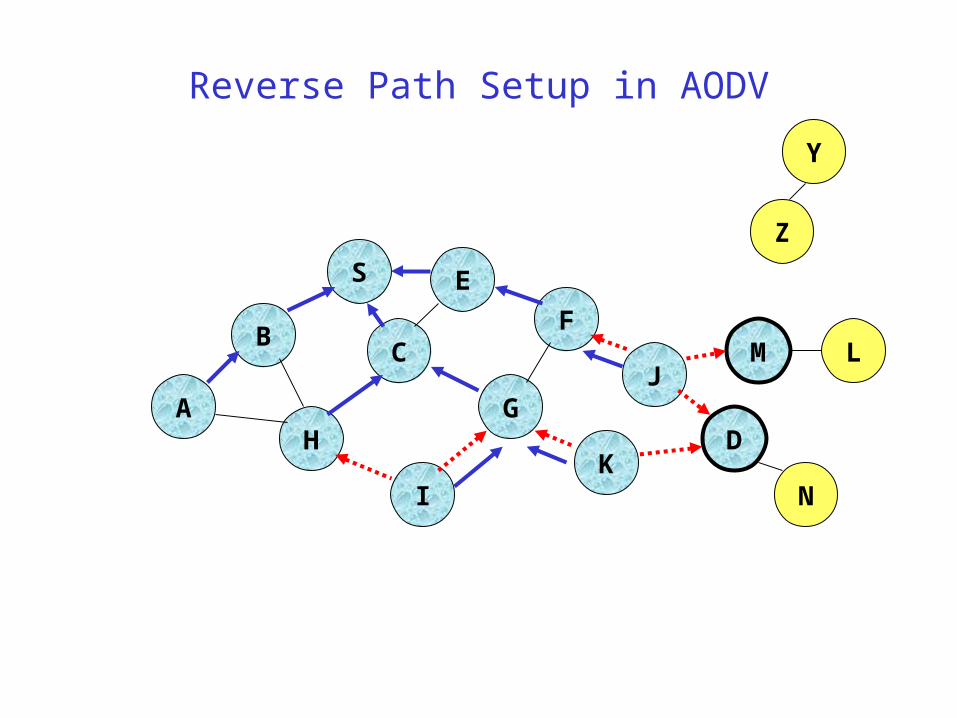
Reverse Path Setup in AODV
B
A
S E
F
H
J
D
C
G
IK
Z
Y
• Node D does not forward RREQ, because node D is the intended target of the RREQ
M
N
L
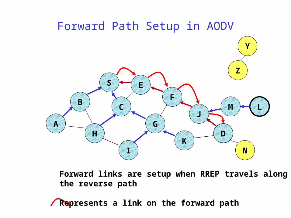
Forward Path Setup in AODV
B
A
S E
F
H
J
D
C
G
IK
Z
Y
M
N
L
Forward links are setup when RREP travels alongthe reverse path
Represents a link on the forward path
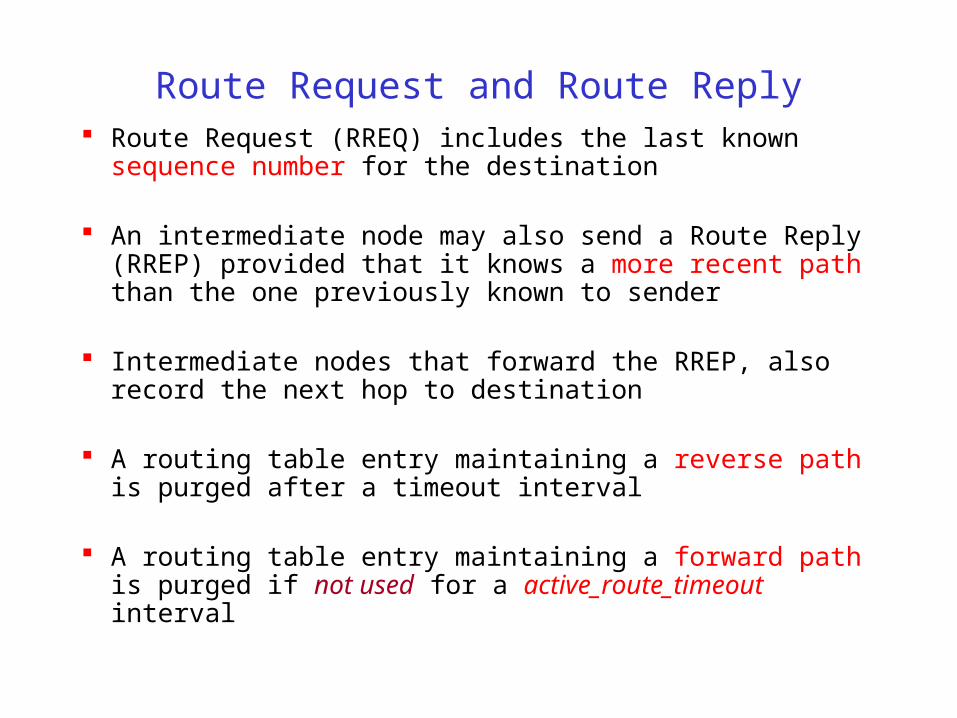
Route Request and Route Reply Route Request (RREQ) includes the last known sequence number
for the destination
An intermediate node may also send a Route Reply (RREP) provided that it knows a more recent path than the one previously known to sender
Intermediate nodes that forward the RREP, also record the next hop to destination
A routing table entry maintaining a reverse path is purged after a timeout interval
A routing table entry maintaining a forward path is purged if not used for a active_route_timeout interval
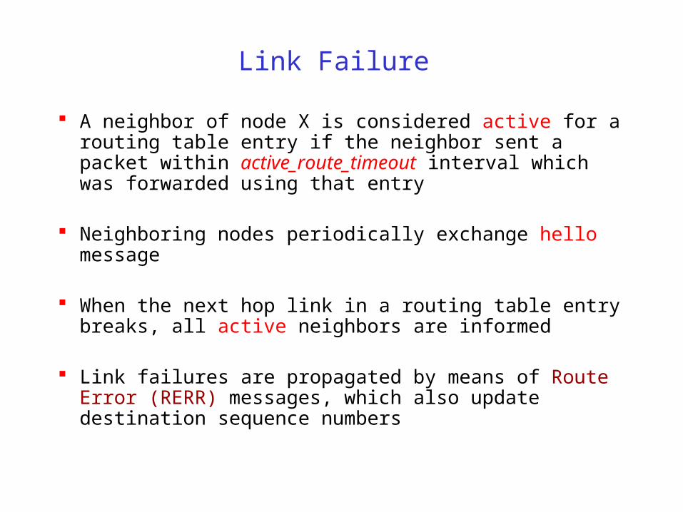
Link Failure
A neighbor of node X is considered active for a routing table entry if the neighbor sent a packet within active_route_timeout interval which was forwarded using that entry
Neighboring nodes periodically exchange hello message
When the next hop link in a routing table entry breaks, all active neighbors are informed
Link failures are propagated by means of Route Error (RERR) messages, which also update destination sequence numbers
Route Error
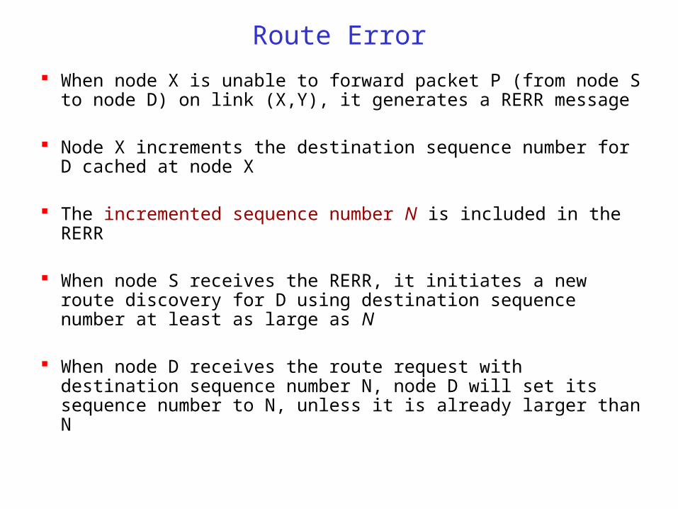
When node X is unable to forward packet P (from node S to node D) on link (X,Y), it generates a RERR message
Node X increments the destination sequence number for D cached at node X
The incremented sequence number N is included in the RERR
When node S receives the RERR, it initiates a new route discovery for D using destination sequence number at least as large as N
When node D receives the route request with destination sequence number N, node D will set its sequence number to N, unless it is already larger than N
AODV: Summary
Routes need not be included in packet headers
Nodes maintain routing tables containing entries only for routes that are in active use
At most one next-hop per destination maintained at each node– DSR may maintain several routes for a single destination
Sequence numbers are used to avoid old/broken routes Sequence numbers prevent formation of routing loops
Unused routes expire even if topology does not change
Other Protocols
Many variations of using control packet flooding for route discovery
Power-Aware Routing [Singh98Mobicom]– Assign a weight to each link: function of energy consumed when
transmitting a packet on that link, as well as the residual energy level– Modify DSR to incorporate weights and prefer a route with the smallest
aggregate weight
Associativity-Based Routing (ABR) [Toh97]– Only links that have been stable for some minimum duration are utilized– Nodes increment the associativity ticks of neighbors by using periodic
beacons
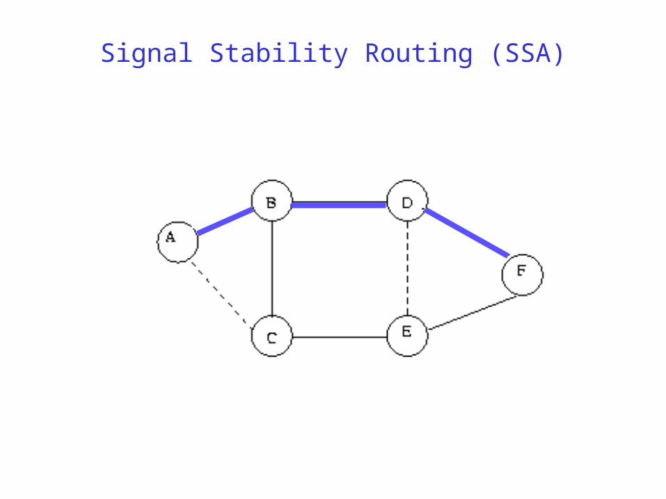
Signal Stability Based Adaptive Routing (SSA) [Dube97]– A node X re-broadcasts a Route Request received from Y only if the
(X,Y) link has a strong signal stability– Signal stability is evaluated as a moving average of the signal strength of
packets received on the link in recent past
Signal Stability Routing (SSA)
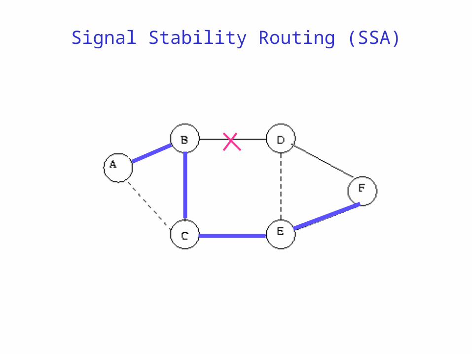
Signal Stability Routing (SSA)
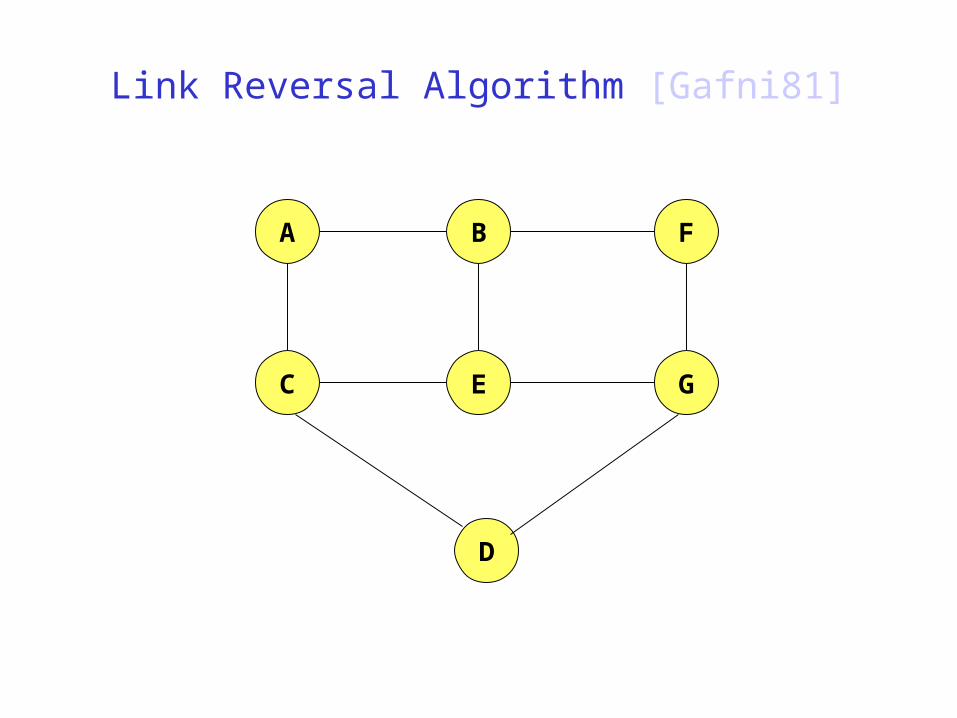
Link Reversal Algorithm [Gafni81]
A FB
C E G
D
Link Reversal Algorithm
A FB
C E G
D
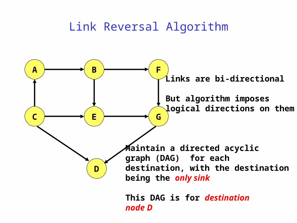
Maintain a directed acyclic graph (DAG) for each destination, with the destinationbeing the only sink
This DAG is for destination node D
Links are bi-directional
But algorithm imposeslogical directions on them
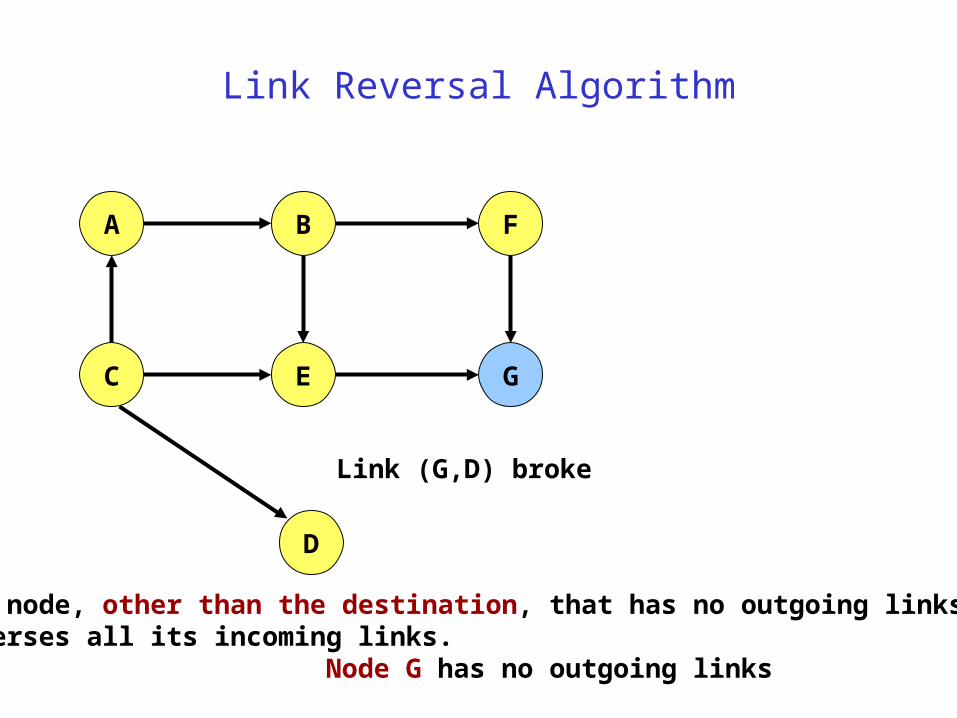
Link Reversal Algorithm
Link (G,D) broke
A FB
C E G
D
Any node, other than the destination, that has no outgoing linksreverses all its incoming links.
Node G has no outgoing links
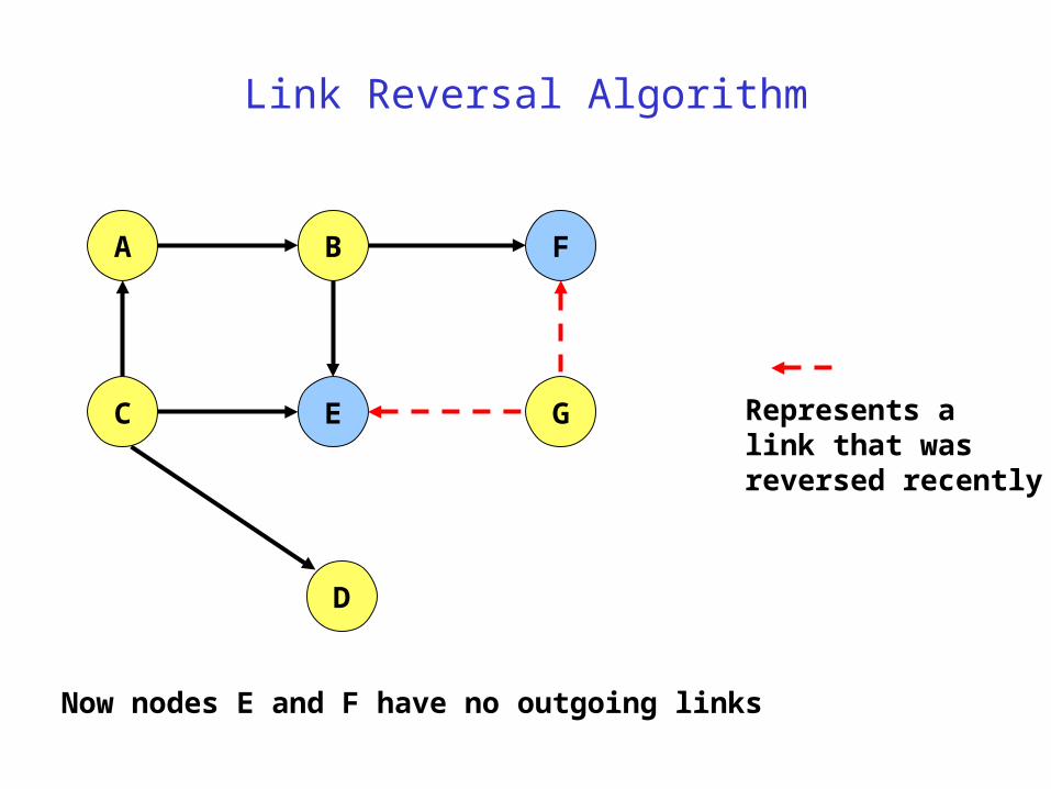
Link Reversal Algorithm
A FB
C E G
D
Now nodes E and F have no outgoing links
Represents alink that wasreversed recently

Link Reversal Algorithm
A FB
C E G
D
Now nodes B and G have no outgoing links
Represents alink that wasreversed recently
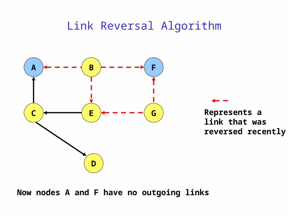
Link Reversal Algorithm
A FB
C E G
D
Now nodes A and F have no outgoing links
Represents alink that wasreversed recently
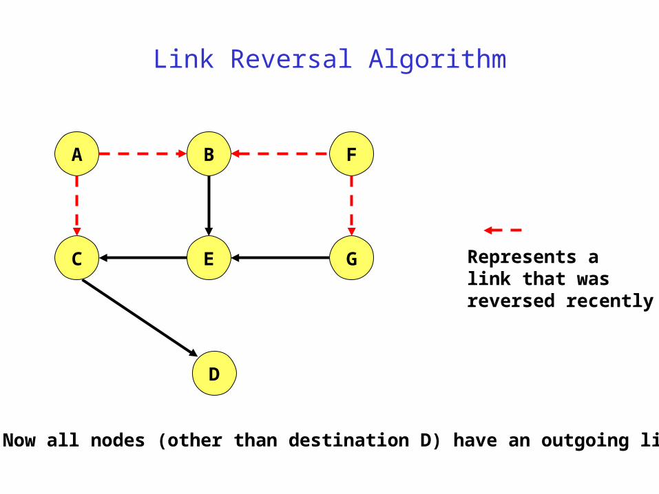
Link Reversal Algorithm
A FB
C E G
D
Now all nodes (other than destination D) have an outgoing link
Represents alink that wasreversed recently
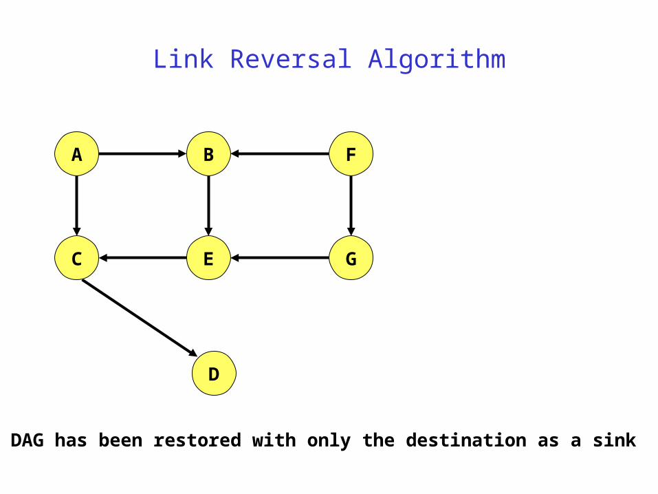
Link Reversal Algorithm
A FB
C E G
D
DAG has been restored with only the destination as a sink
Link Reversal Algorithm
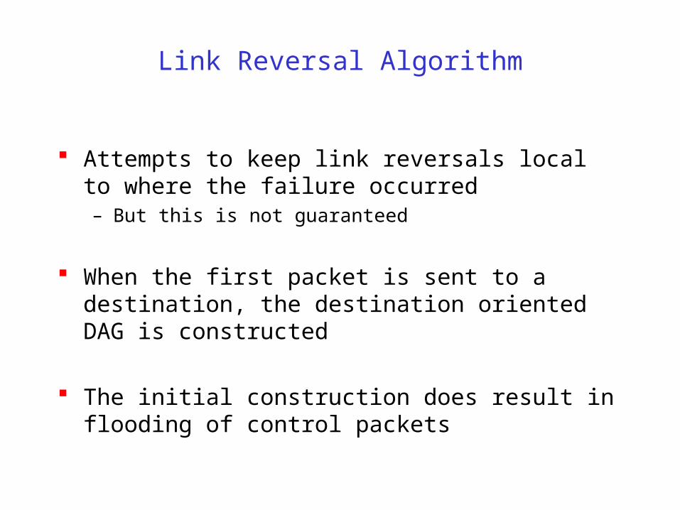
Attempts to keep link reversals local to where the failure occurred– But this is not guaranteed
When the first packet is sent to a destination, the destination oriented DAG is constructed
The initial construction does result in flooding of control packets
Link Reversal Algorithm
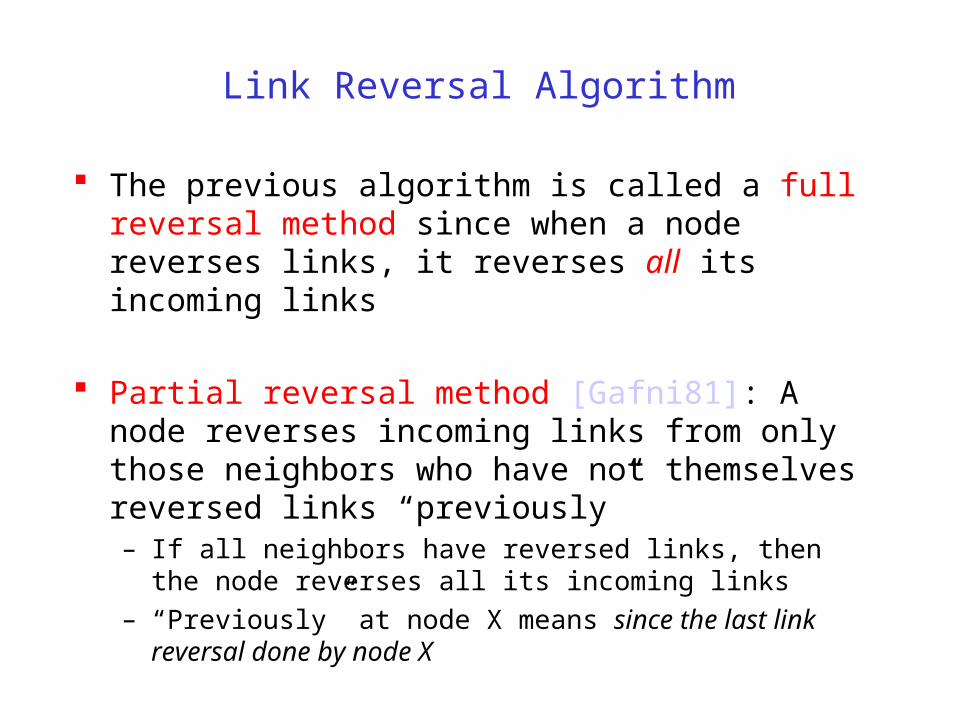
The previous algorithm is called a full reversal method since when a node reverses links, it reverses all its incoming links
Partial reversal method [Gafni81]: A node reverses incoming links from only those neighbors who have not themselves reversed links “previously”– If all neighbors have reversed links, then the node reverses all its
incoming links
– “Previously” at node X means since the last link reversal done by node X

Link Reversal Methods
Advantages– Link reversal methods attempt to limit updates to routing tables at
nodes in the vicinity of a broken link
• Partial reversal method tends to be better than full reversal method
– Each node may potentially have multiple routes to a destination
Disadvantages– Need a mechanism to detect link failure
• hello messages may be used
– If network is partitioned, link reversals continue indefinitely
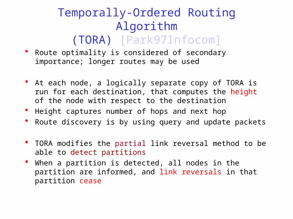
Temporally-Ordered Routing Algorithm(TORA) [Park97Infocom]
Route optimality is considered of secondary importance; longer routes may be used
At each node, a logically separate copy of TORA is run for each destination, that computes the height of the node with respect to the destination
Height captures number of hops and next hop Route discovery is by using query and update packets
TORA modifies the partial link reversal method to be able to detect partitions
When a partition is detected, all nodes in the partition are informed, and link reversals in that partition cease

Asymmetric Algorithms
Clusterhead Gateway Switch Routing (CGSR)– All nodes within a cluster communicate with a clusterhead
– Routing uses a hierarchical clusterhead-to-gateway approach
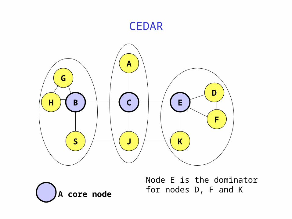
Core-Extraction Distributed Ad Hoc Routing (CEDAR) [Sivakumar99]– A subset of nodes in the network is identified as the core
– Each node in the network must be adjacent to at least one node in the core
– Each core node determines paths to nearby core nodes by means of a localized broadcast
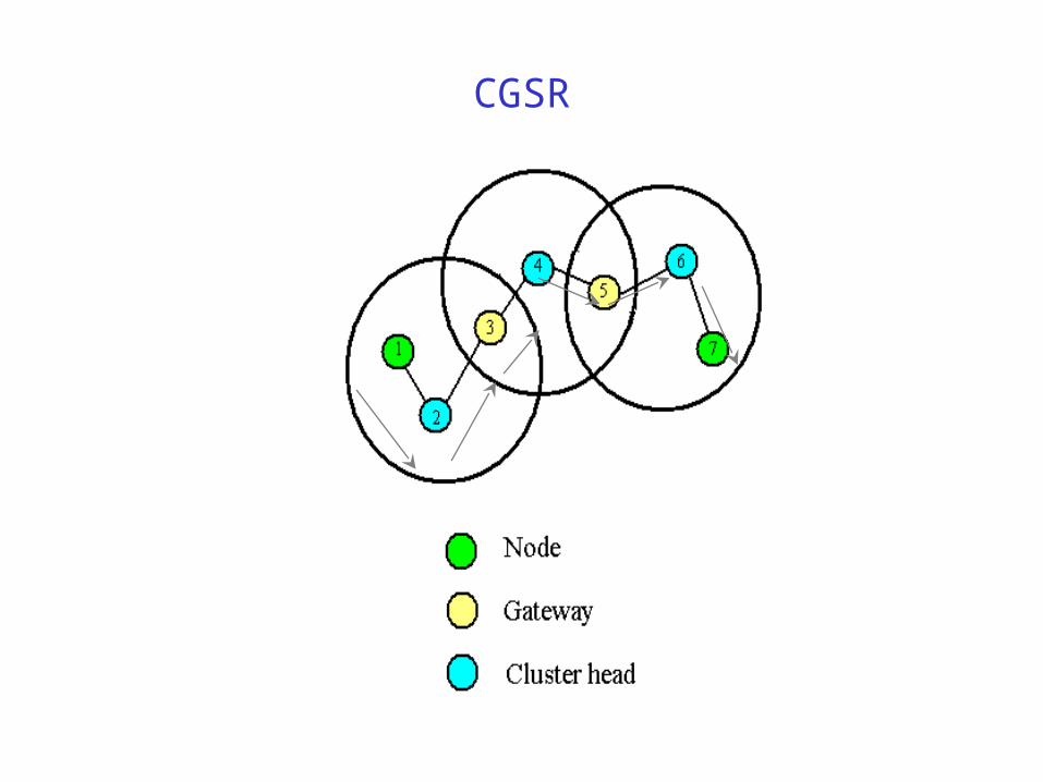
CGSR
CEDAR
B
A
C E
JS K
D
F
H
G
A core node
Node E is the dominator for nodes D, F and K
Proactive Routing Protocols

Destination-Sequenced Distance-Vector (DSDV) [Perkins94Sigcomm]
Each node maintains a routing table which stores– next hop, cost metric towards each destination– a sequence number that is created by the destination itself
Each node periodically forwards routing table to neighbors– Each node increments and appends its sequence number when sending its
local routing table Each route is tagged with a sequence number; routes with greater
sequence numbers are preferred
Each node advertises a monotonically increasing even sequence number for itself
When a node decides that a route is broken, it increments the sequence number of the route and advertises it with infinite metric
Destination advertises new sequence number
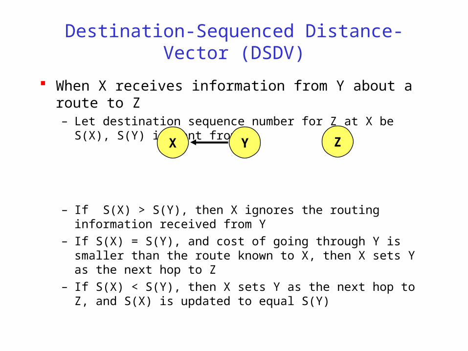
Destination-Sequenced Distance-Vector (DSDV)
When X receives information from Y about a route to Z– Let destination sequence number for Z at X be S(X), S(Y) is sent
from Y
– If S(X) > S(Y), then X ignores the routing information received from Y
– If S(X) = S(Y), and cost of going through Y is smaller than the route known to X, then X sets Y as the next hop to Z
– If S(X) < S(Y), then X sets Y as the next hop to Z, and S(X) is updated to equal S(Y)
X Y Z

Optimized Link State Routing (OLSR) [Jacquet00ietf]
Nodes C and E are multipoint relays of node A– Multipoint relays of A are its neighbors such that each two-hop
neighbor of A is a one-hop neighbor of one multipoint relay of A
– Nodes exchange neighbor lists to know their 2-hop neighbors and choose the multipoint relays
A
B F
C
D
E H
GK
J
Node that has broadcast state information from A
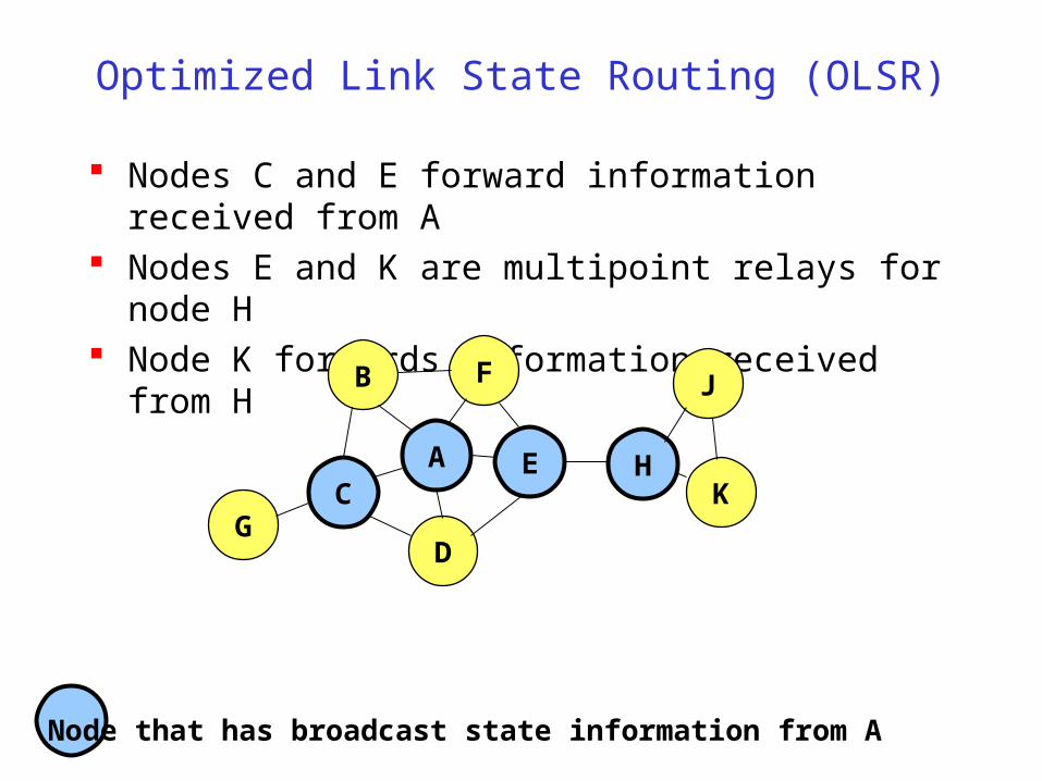
Optimized Link State Routing (OLSR)
Nodes C and E forward information received from A Nodes E and K are multipoint relays for node H Node K forwards information received from H
A
B F
C
D
E H
GK
J
Node that has broadcast state information from A
Hybrid Routing Protocols

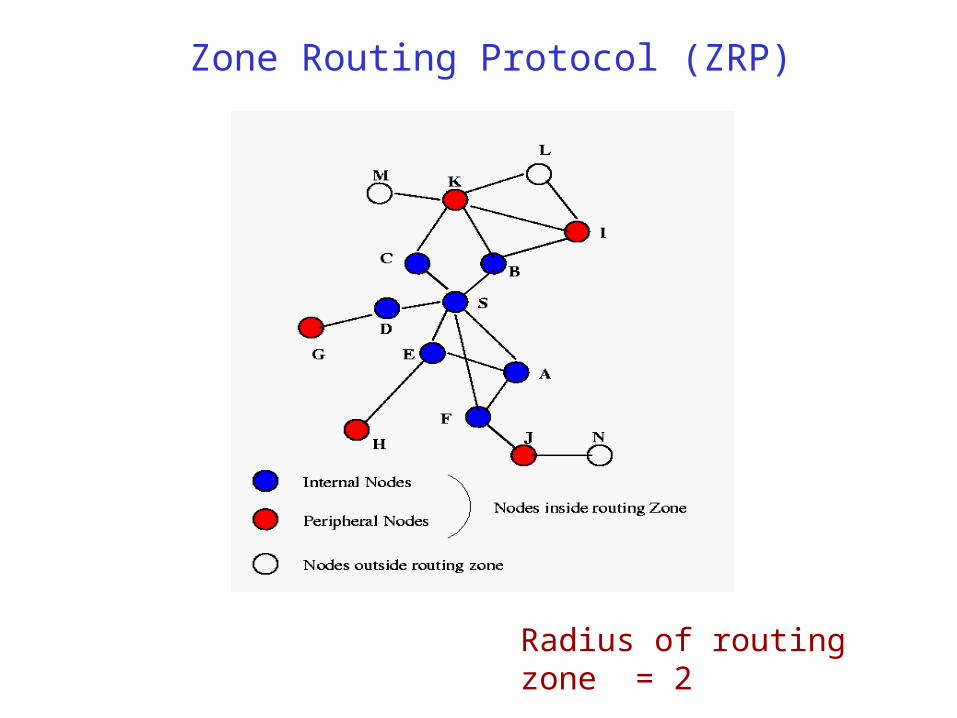
Zone Routing Protocol (ZRP) [Haas98]
ZRP combines proactive and reactive approaches
All nodes within hop distance at most d from a node X are said to be in the routing zone of node X
All nodes at hop distance exactly d are said to be peripheral nodes of node X’s routing zone
Intra-zone routing: Proactively maintain routes to all nodes within the source node’s own zone.
Inter-zone routing: Use an on-demand protocol (similar to DSR or AODV) to determine routes to outside zone.
Zone Routing Protocol (ZRP)
Radius of routing zone = 2
Routing Summary
Protocols– Typically divided into proactive, reactive and hybrid
– Plenty of routing protocols. Discussion here is far from exhaustive
Actual trade-off depends a lot on traffic and mobility patterns– Higher traffic diversity (more source-destination pairs) increases
overhead in on-demand protocols
– Higher mobility will always increase overhead in all protocols