
MNHMT2009 18322 Final - IITKhome.iitk.ac.in/~samkhan/Bio_data/publications/Khandekar... ·...
6
Copyright © 2009 by ASME 1 Proceedings of MNHMT2009 Micro/Nanoscale Heat and Mass Transfer International Conference December 18-21, 2009, Shanghai, China MNHMT2009-18322 HYDRODYNAMIC STUDY OF AN OSCILLATING MENISCUS IN A SQUARE MINI-CHANNEL Yajuvendra Singh Shekhawat Department of Mechanical Engineering Indian Institute of Technology Kanpur Kanpur (UP) 208016 India Sameer Khandekar Department of Mechanical Engineering Indian Institute of Technology Kanpur Kanpur (UP) 208016 India Pradipta Kumar Panigrahi Department of Mechanical Engineering Indian Institute of Technology Kanpur Kanpur (UP) 208016 India ABSTRACT Miniaturized fluidic systems like MEMS may involve single-phase or multi-phase flows with oscillations/ pulsations. Understanding the hydrodynamics of such flows can help in manipulating the performance parameters and improving the efficiency of micro-systems. This work focuses on hydrodynamics of a sinusoidally oscillating meniscus in a square mini-channel. The interfacial contact line behavior of a single oscillating meniscus formed between liquid slug and air, inside the square capillary tube, has been explored. An eccentric cam follower system has been fabricated to provide sinusoidal oscillations of fluid in the square glass capillary having hydraulic diameter of 2.0 mm. Experiments are conducted with two fluids, water and silicon oil. Dynamic contact angle measurements are carried out for water at two oscillating frequencies, 0.25 Hz and 0.50 Hz using high speed videography. It is seen that an increase in the oscillating frequency increases the difference in the advancing angle and receding angle of the meniscus, with the static contact angle of water on glass surface around 21°. For silicon oil the experiments have been performed at eight different frequencies in the range of 0.20 Hz and 1.00 Hz. It is seen that the meniscus is pinned at the extreme end of the stroke, unlike that in the case of water, and there is a film of silicon oil during oscillations. The thickness of the film formed increases with increase in oscillating frequency. There is considerable difference in the hydrodynamics of silicon oil and water. INTRODUCTION Improvements in the micro-fabrication capability have given rise to many micro systems involving heat and mass transfer phenomena. The primary reason of enhancement in the heat and species transport is the increased surface area to volume ratio. Miniaturized fluidic systems may involve single- phase as well as multi-phase flow. There are numerous applications involving two-phase or multi-phase flow in mini/micro geometries, i.e. pulsating heat pipes, fuel cells, lab- on-a-chip devices, digital fluidics etc. Because of the dominance of surface tension forces, Taylor bubble flow is a common two-phase pattern observed in mini/micro channels [1, 2]. The motion of the phases in these systems may not necessarily be steady; unsteady behavior, like oscillations or pulsations, is often observed. These oscillations can be naturally occurring, as in pulsating heat pipes, or induced in micro-mixing devices like oscillating polymerase chain reaction device. The aim of the present study is to understand two-phase interfacial flow in mini-channels under oscillating flow conditions. White and Beardmore [1] experimentally found out that at Bond number less than 4, one can consider the geometry to be small. This value, of course varies a bit, depending on the wettability of the surface which gives different equilibrium contact angles. Angeli and Gavriilidis [2] have reviewed the work done to understand the hydrodynamics of Taylor flow (two-phase flow occurring in minichannels) in capillaries. The hydrodynamic characteristics reviewed were, thickness of film that surrounds the bubbles, bubble shape and velocity, bubble
Transcript of MNHMT2009 18322 Final - IITKhome.iitk.ac.in/~samkhan/Bio_data/publications/Khandekar... ·...

Copyright © 2009 by ASME 1
Proceedings of MNHMT2009
Micro/Nanoscale Heat and Mass Transfer International Conference December 18-21, 2009, Shanghai, China
MNHMT2009-18322
HYDRODYNAMIC STUDY OF AN OSCILLATING MENISCUS IN A SQUARE MINI-CHANNEL
Yajuvendra Singh Shekhawat Department of Mechanical Engineering Indian Institute of Technology Kanpur
Kanpur (UP) 208016 India
Sameer Khandekar Department of Mechanical Engineering Indian Institute of Technology Kanpur
Kanpur (UP) 208016 India
Pradipta Kumar Panigrahi Department of Mechanical Engineering Indian Institute of Technology Kanpur
Kanpur (UP) 208016 India
ABSTRACT Miniaturized fluidic systems like MEMS may involve
single-phase or multi-phase flows with oscillations/ pulsations. Understanding the hydrodynamics of such flows can help in manipulating the performance parameters and improving the efficiency of micro-systems. This work focuses on hydrodynamics of a sinusoidally oscillating meniscus in a square mini-channel. The interfacial contact line behavior of a single oscillating meniscus formed between liquid slug and air, inside the square capillary tube, has been explored. An eccentric cam follower system has been fabricated to provide sinusoidal oscillations of fluid in the square glass capillary having hydraulic diameter of 2.0 mm. Experiments are conducted with two fluids, water and silicon oil. Dynamic contact angle measurements are carried out for water at two oscillating frequencies, 0.25 Hz and 0.50 Hz using high speed videography. It is seen that an increase in the oscillating frequency increases the difference in the advancing angle and receding angle of the meniscus, with the static contact angle of water on glass surface around 21°. For silicon oil the experiments have been performed at eight different frequencies in the range of 0.20 Hz and 1.00 Hz. It is seen that the meniscus is pinned at the extreme end of the stroke, unlike that in the case of water, and there is a film of silicon oil during oscillations. The thickness of the film formed increases with increase in oscillating frequency. There is considerable difference in the hydrodynamics of silicon oil and water.
INTRODUCTION Improvements in the micro-fabrication capability have
given rise to many micro systems involving heat and mass transfer phenomena. The primary reason of enhancement in the heat and species transport is the increased surface area to volume ratio. Miniaturized fluidic systems may involve single-phase as well as multi-phase flow. There are numerous applications involving two-phase or multi-phase flow in mini/micro geometries, i.e. pulsating heat pipes, fuel cells, lab-on-a-chip devices, digital fluidics etc. Because of the dominance of surface tension forces, Taylor bubble flow is a common two-phase pattern observed in mini/micro channels [1, 2]. The motion of the phases in these systems may not necessarily be steady; unsteady behavior, like oscillations or pulsations, is often observed. These oscillations can be naturally occurring, as in pulsating heat pipes, or induced in micro-mixing devices like oscillating polymerase chain reaction device.
The aim of the present study is to understand two-phase interfacial flow in mini-channels under oscillating flow conditions. White and Beardmore [1] experimentally found out that at Bond number less than 4, one can consider the geometry to be small. This value, of course varies a bit, depending on the wettability of the surface which gives different equilibrium contact angles. Angeli and Gavriilidis [2] have reviewed the work done to understand the hydrodynamics of Taylor flow (two-phase flow occurring in minichannels) in capillaries. The hydrodynamic characteristics reviewed were, thickness of film that surrounds the bubbles, bubble shape and velocity, bubble

2
and slug length, flow patterns in the liquid slug, and pressure drop in the system. The review clearly suggests that most of the work has been carried out for unidirectional Taylor bubble flow in capillaries. Two-phase flow in non-circular channels is not commonly addressed in literature. It should also be noted that there is scarcely any work done on oscillatory Taylor flow.
Recently, Lips and Bonjour [4] carried out experiments and reported the curvature of meniscus during oscillating Taylor bubble flow of pentane. These values of the front and rear meniscus were then used to create a correlation between curvature and velocity specifically for pentane. This correlation was then used to find the pressure drop due to deformation of the meniscus. This pressure drop cannot be neglected, particularly at low interface velocities. Moreover, for particular excitation frequencies, resonance phenomena and their consequences on the flow characteristics were highlighted. Qiu and Wang [5] carried out experiments to show the effect of oscillating frequency on interfacial film thickness. They used a novel optical technique to find the film thickness around a bubble in water for oscillating frequency up to 40 Hz. Many relations are available for film thickness of a Taylor bubble, under unidirectional quasi-steady flow conditions, suggesting that the film thickness increases with increase in the velocity. However, during oscillatory conditions, the bulk flow velocity varies from 0 to Vmax. There has been some work reported on evaporating meniscus. Stephan & Hohmann [3] reported the temperature distribution at the micro-region between the adsorbed, non-evaporating film and the macroscopic region of a liquid meniscus. It was observed that the temperature in the micro-region drastically drops and a high heat transfer is obtained at that region with upto 50 % of evaporation taking place in that region. It is because of this characteristic, two-phase flow is used in most of the modern heat transfer systems. The length of the micro-region depends on the wetting characteristic, or the apparent contact angle, which is the macroscopic representation of the wetting characteristic.
It is clear from the literature that under the influence of the surface tension forces, dominant in mini-micro systems, and oscillating inertia forces, the film and meniscus hydrodynamics will strongly affect the ensuing heat/mass transfer coefficients. Such flow conditions have not been studied extensively. To address these issues, in the current work, a single oscillating meniscus is visualized in square minichannel using a high speed camera under imposed sinusoidal oscillations. The recorded images are then used to carry out the contact angle measurements of water meniscus at different oscillating frequencies. Experiments using Silicon oil are also carried out. Silicon oil behaves very differently from water meniscus. Pinning of the contact point of silicon oil meniscus and the subsequent formation of silicon oil film is observed. The variation of film thickness with the oscillating meniscus is also measured.
NOMENCLATURE d Hydraulic diameter, m
f Frequency, Hz
g Acceleration due to gravity, m/s2
L Length of stroke, m
t Time, s
V Linear velocity, m/s
x Displacement, m
ω Angular frequency, rad/s
ρ Density, kg/m3
μ Dynamic Viscosity, Ns/m2
σ Surface tension, N/m
ν Kinematic viscosity, m2/s
Re Reynolds number, Re ( ) /V dρ μ=
Bo Bond number, 2Bo ( ) /g dρ σ= ⋅ ⋅
Ca Capillary number, Ca /Vμ σ= ⋅
We Weber number, 2We ( ) /V dρ σ= ⋅ ⋅
St Strouhal number, 2St ( ) /f d ν= ⋅
EXPERIMENTAL SETUP The experimental setup for the present work has four basic
parts; Light source, CCD Camera, Square mini-channel, and Cam-follower system. Figure 1 shows an image of the complete setup.
Fig.1: The picture of the experimental setup. While doing the experiments, the CCD camera, fitted with a macro lens, was placed close to the channel.

3
Moritex 150 W halogen light source (MHAB-150W) is
used as the light source. It is provided with an external linear intensity control, this helps in adjusting the intensity of light coming out. Moritex fiber bifurcated light guide (MWG-500R) is used to direct the light from the light source to the square capillary.
Imperx camera (IPX-VGA210-L) fitted with a 40mm extension tube and 25 mm objective lens is used for visualizing the oscillating meniscus at different locations in the mini-channel at different frequencies. It is a fast progressive scan CCD camera, which provides maximum resolution of 640 pixels X 480 pixels and can acquire images at 210 frames per second at full resolution. The field of view of 3.0 mm X 2.25 mm at a spatial resolution of 4.7 microns/ pixel was achieved. A dual channel frame grabber card is used to grab frames from the Imperx® camera, and Streampix® software records these images from the frame grabber to the hard drive of computer. The acquired images are then digitally processed to find the dynamic contact angle.
The square minichannel is fabricated using four glass pieces of thickness 2.0 mm and length of 110.0 mm. Two of the pieces have width of 30.0 mm and the other two have width of 14.0 mm. The 14.0 mm pieces are enclosed in between the 30.0 mm pieces as shown in Figure 2, making a 110.0 mm long square passage of edge 2.0 mm having a hydraulic diameter of 2.0 mm. To prevent surface contamination, utmost care is taken in using adhesive to enclose the glass pieces. After the assembly, the channel is thoroughly cleaned (by alternate application of ethanol and acetone) not only by mechanical brushing but also by keeping the assembly in a sonicator for two hours.
The most important part of the setup is the cam-follower system; it is fabricated to produce sinusoidal oscillating motion. Figure 3 gives the detail about the system. An eccentric cam with a spring loaded follower is used in the system. Theoretically if an eccentric cam is rotated at a constant angular velocity, the follower oscillates sinusoidally. This sinusoidal motion is transferred to the fluid in the minichannel using piston-cylinder mechanism, where the syringe acts as a cylinder and the follower as a piston. Eq. 1 gives the theoretical equation representing the location of the meniscus from the bottom dead center for varying time.
( ) ( / 2) (1 sin( ( / 2))x t L tω π= ⋅ + − (1)
To confirm that the cam-follower system generate
sinusoidal oscillations, images of the oscillating meniscus in a 1.85 mm round capillary are captured by the CCD camera, and the recorded displacement data is superimposed on a theoretical sinusoidal curve represented by Eq. 1 as shown in figure 4. It can be seen from figure 4 that the sinusoidal motion is almost achieved with a slight deviation. This slight deviation is attributed to friction in the system. The maximum deviation is less than 10% and hence theoretical displacement and velocity values are used as a basis to calculate the relevant dimensionless numbers.
Fig. 2: Schematic of the fabricated square minichannel.
Fig. 3: (a) Schematic and, (b) photograph of the oscillating mechanism used in the experiment.
Fig. 4: Displacement v/s time.

4
RESULTS AND DISCUSSION The experiments are carried out using two fluids: (1)
Deionized water, and (2) Silicon oil. Table 1 gives the property of these fluids. Deionized Water
Experiments with water are carried out at two oscillating frequencies, i.e., 0.25 Hz, and 0.50 Hz. During the oscillations, velocity of the meniscus varies continuously, as given in Eq. 2; it is obtained by differentiating Eq. 1 with respect to time:
( ) ( / 2) cos( ( / 2))v t L tω ω π= ⋅ ⋅ − (2) The dimensionless numbers representing the relative
importance of the forces acting near the interfacial region are; Reynolds number, Bond number, Capillary number and Weber number. Additionally, Strouhal number is one other dimensionless number which gives the ratio of time scale for momentum diffusion to the induced time scale of externally imposed oscillations.
During the oscillations, velocity of the meniscus continuously changes, resulting in dynamic variation of Reynolds, Capillary, and Weber number. Hence these are represented by the maximum velocity. Table 2 presents the value of all the dimensionless numbers for the two experimental conditions on water. In Taylor bubble flow, Reynolds, Bond and capillary number affect the shape and motion of the interfaces. Reynolds number is the ratio of inertial to viscous force, increase in the value of Re increases the film thickness and the velocity difference between the phases. Bond number gives the ratio of gravitational or body force to surface tension force. The channels are generally regarded small when surface tension forces dominate gravitational forces. Investigators have suggested different values of Bo below which channels can be considered small. Another important number is Capillary number, which is the ratio of viscous forces to surface tension forces at the interface. It determines the shape of Taylor bubble. Weber number is the ratio of inertial to surface tension force at the interface. In unidirectional flow system the only relevant time scale is the momentum diffusion time. Here, in contrast, the flow is characterized by a second imposed time scale that is due to the oscillatory pressure gradient and the form of the resulting flow depends on the ratio of the diffusion time to the imposed time scale, i.e. Strouhal number. The magnitude of St determines the importance of acceleration effect in the fluid relative to the viscous effects (diffusion of momentum). In this role, it is evident that St can be considered as a Reynolds number, based on a characteristic “velocity” ~ f d.
Table 1: Physical properties of Deionized Water and
Silicon oil at 26oC Properties Water Silicon Oil
Density (kg/m3) 996.8 960.0
Dynamic viscosity (Ns/m2) 0.8796 X 10⁻³ 48 X 10-3
Kinematic viscosity (m2/s) 0.8824 X 10⁻⁶ 50 X 10-6
Surface tension (N/m) 0.0728 0.0207
Table 2: Dimensionless numbers corresponding to the
experiments with water. Dimensionless
number Water Oscillating
at 0.25 Hz Water Oscillating
at 0.5 Hz
Remax 44.47 88.94
Bo 0.53 0.53
Camax 2.36 x 10⁻⁴ 4.71 x 10⁻⁴
Wemax 1.05 x 10⁻² 4.21 x 10⁻²
St 1.13 2.26
In the experiments the oscillating meniscus is visualized,
and the variation in the contact angle made by water meniscus with the wall is obtained. Contact angle of water at static condition varies from 19.8o to 21.8o, with average value of 21o.
Figure 5 (ii) shows the images of the oscillating meniscus at locations marked on the displacement-time graph shown in Figure 5 (i). Points a, b, c, and d show the advancing meniscus and e, f, g, and h show the receding meniscus respectively. Points d and e are at the top dead end of the stroke, and points h and a are at bottom dead end of the stroke. There is small change in the curvature of the meniscus; to quantify this change the contact angle is measured by magnified videography.
Fig. 5: (i) Displacement-time graph, (ii) Images of a water meniscus oscillating at 0.50 Hz.
5
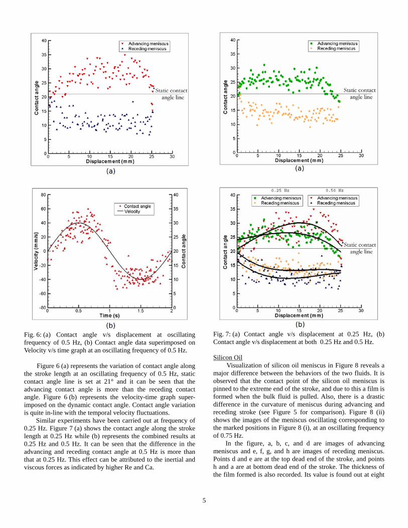
Fig. 6: (a) Contact angle v/s displacement at oscillating frequency of 0.5 Hz, (b) Contact angle data superimposed on Velocity v/s time graph at an oscillating frequency of 0.5 Hz.
Figure 6 (a) represents the variation of contact angle along
the stroke length at an oscillating frequency of 0.5 Hz, static contact angle line is set at 21° and it can be seen that the advancing contact angle is more than the receding contact angle. Figure 6 (b) represents the velocity-time graph super-imposed on the dynamic contact angle. Contact angle variation is quite in-line with the temporal velocity fluctuations.
Similar experiments have been carried out at frequency of 0.25 Hz. Figure 7 (a) shows the contact angle along the stroke length at 0.25 Hz while (b) represents the combined results at 0.25 Hz and 0.5 Hz. It can be seen that the difference in the advancing and receding contact angle at 0.5 Hz is more than that at 0.25 Hz. This effect can be attributed to the inertial and viscous forces as indicated by higher Re and Ca.
Fig. 7: (a) Contact angle v/s displacement at 0.25 Hz, (b) Contact angle v/s displacement at both 0.25 Hz and 0.5 Hz.
Silicon Oil
Visualization of silicon oil meniscus in Figure 8 reveals a major difference between the behaviors of the two fluids. It is observed that the contact point of the silicon oil meniscus is pinned to the extreme end of the stroke, and due to this a film is formed when the bulk fluid is pulled. Also, there is a drastic difference in the curvature of meniscus during advancing and receding stroke (see Figure 5 for comparison). Figure 8 (ii) shows the images of the meniscus oscillating corresponding to the marked positions in Figure 8 (i), at an oscillating frequency of 0.75 Hz.
In the figure, a, b, c, and d are images of advancing meniscus and e, f, g, and h are images of receding meniscus. Points d and e are at the top dead end of the stroke, and points h and a are at bottom dead end of the stroke. The thickness of the film formed is also recorded. Its value is found out at eight

6
different oscillating frequencies. The values of dimensionless numbers corresponding to those eight frequencies are given in Table 3. Figure 9 shows the variation of average film thickness (at station A, which is at the mid point of the stroke length) with the change in frequency. It is observed that the film thickness increases with increase in oscillating frequency.
Fig. 8: (i) Displacement-time graph, (ii) Images of a meniscus oscillating at 0.75 Hz.
Fig. 9: Film thickness at Station A as a function of frequency.
Table 3: Dimensionless numbers corresponding to experiments carried out on Silicon Oil.
Frequency (Hz) Remax Bo Camax Wemax St
0.20 0.8296 1.810 0.0481 0.0398 0.0160
0.35 1.4518 1.810 0.0841 0.1221 0.0280
0.45 1.8666 1.810 0.1082 0.2019 0.0360
0.57 2.3643 1.810 0.1371 0.3240 0.0456
0.66 2.7376 1.810 0.1587 0.4344 0.0528
0.76 3.1524 1.810 0.1827 0.5760 0.0608
0.86 3.5628 1.810 0.2068 0.7376 0.0688
0.98 4.0650 1.810 0.2357 0.9579 0.0784
SUMMARY AND CONCLUSIONS A simple cam-follower system is designed and fabricated
to produce the desired sinusoidal oscillating motion of a meniscus. Experiments are carried out to visualize the oscillating meniscus formed. Two fluids are used for the experiments. Dynamic contact angle measurements are carried out for water at two oscillating frequencies. It is observed that advancing contact angle is more than static contact angle and receding contact angle is less than static contact angle. The difference in the advancing and receding contact angle increases with increase in the oscillating frequency. For silicon oil, pinning of the contact point of meniscus and the subsequent formation of film is observed. The thickness of the film formed increases with increase in the oscillating frequency.
ACKNOWLEDGMENTS The work is partially funded by the Department of Science
and Technology (Project #: DST/CHE/20060304) and Board of Research for Nuclear Sciences, BRNS (Project #: BRNS/ME/20050292), Government of India. Contribution of the IITK-SURGE program (Ms. Sria Mujumdar, VNIT, Nagpur, India, for additional measurements) is also acknowledged.
REFERENCES [1] White, E. T., Beardmore, R. H. The velocity of rise of
single cylindrical air bubbles through liquids contained in vertical tubes. Chem. Engg. Science, 1962, 17, 351-361.
[2] Angeli P., Gavriilidis A., Hydrodynamics of Taylor flow in small channels: A review. Proc. IMechE, 222, 2008, 737-751.
[3] Hohmann, C., Stephan, J. Microscale temperature measurement at an evaporating meniscus. Exp. Therm. and Fluid Sci., 2002, 26, 157-162.
[4] Lips S., Bonjour J., Oscillating two-phase flow in a capillary tube: Experiments and modeling. Proc. 14th Int. Heat Pipe Conf., Florianopolis, Brazil, 2007, 292-297.
[5] Qiu H., Wang X., Experimental study on Interfacial Film Dynamics of Oscillating Multiphase micro flows. 13th Int. Symp. Application of Laser Technology in Fluid Mechanics, Lisbon, Portugal, 2006.


