
mizer.pdf
38
Wood-Mizer ® Thin-Kerf Blades Blade Handbook A Guide To Understanding Bandsaw Blade Terminology & Optimizing Blade Performance Safety is our #1 concern! Read and understand all safety information and instructions before oper- ating, setting up or maintaining this machine. May 2007 Form #600
Transcript of mizer.pdf

Wood-Mizer® Thin-Kerf Blades
Blade Handbook
A Guide To Understanding Bandsaw Blade Terminology & Optimizing Blade
Performance
Safety is our #1 concern! Read and understandall safety information and instructions before oper-ating, setting up or maintaining this machine.
May 2007Form #600

Table of Contents Section-Page
SECTION 1 BLADE INTRODUCTION 1-1
1.1 Best Blade In The Industry........................................................................................ 1-2DoubleHard Blades.......................................................................................................... 1-2SilverTip Blades ............................................................................................................... 1-2
1.2 Which Blade Should You Use?................................................................................. 1-3
SECTION 2 BLADE GEOMETRY 2-1
2.1 Tooth Spacing............................................................................................................ 2-22.2 Radius ........................................................................................................................ 2-32.3 Tooth Height (Depth Of Gullet) ................................................................................ 2-42.4 Hook Angle ............................................................................................................... 2-52.5 Face Angle................................................................................................................. 2-62.6 Tooth Set ................................................................................................................... 2-72.7 Recommended Blade Specifications ......................................................................... 2-8
SECTION 3 BLADE MAINTENANCE 3-1
3.1 General Blade Maintenance Information .................................................................. 3-13.2 Blade Life Expectancy .............................................................................................. 3-43.3 Automatic Blade Sharpener Option........................................................................... 3-73.4 Toothsetter/Gauge Option ......................................................................................... 3-8
SECTION 4 BLADE HANDLING 4-1
4.1 Coiling The Blade...................................................................................................... 4-14.2 Uncoiling The Blade.................................................................................................. 4-34.3 Inverting The Blade................................................................................................... 4-54.4 Storing Blades ........................................................................................................... 4-74.5 Packaging Blades For Shipping................................................................................. 4-8
SECTION 5 TROUBLESHOOTING 5-1
5.1 Blade Breakage.......................................................................................................... 5-15.2 Blade Performance .................................................................................................... 6-15.3 Special Problem Wood Types or Conditions ............................................................ 6-2
INDEX I
ii BMdoc071312 Table of Contents

Blade Introduction
Blade Introduction BMdoc071312 1-1
1SECTION 1 BLADE INTRODUCTION
Wood-Mizer is the worldwide leader in portable bandmills and other wood-processingequipment. Wood-Mizer is also the only sawmill manufacturer that produces narrow-bandthin-kerf blades. When we introduced our first portable bandmill 20 years ago, one thingquickly became clear: We needed better blades than were currently available.
After evaluating the materials and processes others were using to make blades,Wood-Mizer decided the only option was to manufacture its own blades. This decisionhas led to advancements in blade materials and processing that have revolutionized theindustry. Advances in developing bigger and better sawmills, combined with our countlesshours and dollars spent on blade technology have resulted in customers being able tosaw more lumber faster using less horsepower than traditional sawmills.
The blade can cause the success or failure of a cutting operation. It is important for saw-yers to understand definitions and theories about blades. What our research has shownto be the most productive has not always matched what the textbooks say. We believethis is due to the low horsepower and narrow width of our blades as compared to largerproduction mills. This section explains narrow-band blades used with the Wood-Mizer®.
See also Section 3, Blade Maintenance or the Blade Maintenance Video for blade sharp-ening techniques and troubleshooting.
Wood-Mizer® blades are available in various widths, thicknesses and tooth profiles to sat-isfy any cutting application. The following chapters provide information that will help youdetermine which blade to use. A Customer Service Representative can also help youdecide which blade is best for your cutting application (1-800-525-8100). You can alsocall Wood-Mizer Blades at 1-800-522-5760 and speak with a blade consultant or visit ourwebsite at www.woodmizerblades.com.

Blade IntroductionBest Blade In The Industry1
1-2 BMdoc071312 Blade Introduction
1.1 Best Blade In The Industry
Wood-Mizer® is the only sawmill manufacturer that makes its own blades.
Wood-Mizer® builds quality into every blade we manufacture. From the selection of theraw materials to the output of the final product, every step of the manufacturing process iscontrolled and inspected. Over one hundred separate tests and inspections ensure thequality of every blade that comes to you in a Wood-Mizer® box of blades.
Each Wood-Mizer® blade tooth is individually measured and set by computer-controlledequipment during the manufacturing process.
Wood-Mizer® is the only company that stamps an identification number onto every bladewe manufacture. This number allows us to track the blades from the raw material to theend user, YOU. If there’s ever a question about performance or quality, we are able totrack the blade back through the manufacturing process and identify potential areas ofimprovement. The identification number assures you of a product that performs well nowand will continue to improve as we discover even better ways of producing blades thatconsistently give maximum performance.
DoubleHard Blades
Wood-Mizer DoubleHard blades are a combination of two different metallurgical tech-niques that result in superior hardness and toughness not found in other blades. TheDoubleHard blades use high-quality steel and the teeth are induction hardened (Double-Hard-ened) so they stay sharper longer and can be resharpened often. The performanceof these blades means higher productivity and lower cost per board foot.
SilverTip Blades
This blade is made specifically to meet the needs of the resaw industry and is alower-cost alternative for customers not requiring multiple resharpenings.
The SilverTip features much tighter manufacturing specs than the competition’s blades.The SilverTip is made with a higher carbon content than DoubleHard blades, with ahigh-durability steel suited to high-volume sawing environments. SilverTip blades will typ-ically provide fewer resharpenings than DoubleHard blades.

Blade IntroductionWhich Blade Should You Use? 1
1.2 Which Blade Should You Use?
See Figure 1-1. Wood-Mizer's blade part numbers are made up of ten or twelve charac-ters. See the table below for a description of what each character of the blade part num-ber represents. Note that Wood-Mizer® blades can be ordered in almost any length.Standard blades are kept in stock and are available for same day shipment. Customlengths are normally available for shipment within two days of order.
Three factors should be considered when determining which blade is best suited for yourapplication:
1. Hook Angle.
The hook angle (how far the tooth leans forward) should be chosen based on the type ofwood you are cutting. Softwoods require higher hook angles (10-13°). Hard, frozen orknotty woods require lower hook angles (4-10°). The 10° hook angle is a good all-purposeprofile recommended for most sawing applications.
2. Blade Thickness.
Thicker blades provide faster feed rates and better cutting performance but require higherhorsepower. Thicker blades also perform better in difficult sawing conditions such asknotty, frozen, dry or extremely hard material. Thinner blades provide longer flex life andare recommended for sawmills with lower horsepower or where production/speed is not aprimary factor in your application.
B HOW SOLD;B=BOX OF BLADES, U=UNIT (SINGLE BLADE)
2 THICKNESS; 1=.035", 2=.042", 3=.045", 4=.055”, 5=.050”,6=.038”
7 TOOTH SPACING; 7=7/8", 5=5/8”
5 WIDTH; 4, 5, 6, 7 OR 8 QUARTERS OF AN INCH (except 1 1/8” blades)
74 SILVERTIP ONLY
158 LENGTH IN INCHES158 for LT15/28/30/40, 184 for LT60/70 or 144 for LT10
10
SPECIAL CONDITION;4=EXTREMELY KNOTTY OR FROZEN WOOD SERIES;
9=HARD OR FROZEN WOOD SERIES; 10=STANDARD SERIES; 13=SOFTWOOD SERIES
SS = STANDARD LENGTH; C = CUSTOM LENGTH
FIG. 1-1
Blade Introduction BMdoc071312 1-3

Blade IntroductionWhich Blade Should You Use?1
3. Blade Width.
As with blade thickness, blade width provides faster feed rates and increased cutting per-formance, but require higher horsepower. Wide blades can also be resharpened moreoften, resulting in more production during the life of the blade. Narrow blades perform bet-ter on low-horsepower sawmills and in some difficult sawing conditions.
See Table 1-1. See the chart below for blade recommendations for various equipment.
SilverTip SeriesWidth Thick Tooth
SpaceProfile Series # Horsepower Application
1” .035” 5/8” 12° B15474xxx12 10-15 electric Resawing narrow-width material.
1” .042” 7/8” 9° B274xxx9 10-15 electric Resawing extreme hard/frozen woods.
1” .042” 7/8” 10° B274xxx10 10-15 electric Resawing medium/mixed hardwoods.
1 1/8” .038” 5/8” 12° B656xxx12 10-15 electric Resawing narrow width mixed hardwoods.
1 1/4” .042” 7/8” 10° B27574xxx10 5-15 gas/diesel10-15 electric
Sawing/Resawing medium/mixed hardwoods.
1 1/2” .045” 7/8” 13° B37674xxx13 16-42 gas/diesel15-25 electric
Sawing/Resawing medium/mixed hardwoods.
1 1/2” .045” 7/8” 10° B37674xxx10 16-42 gas/diesel15-25 electric
Sawing/Resawing medium/mixed hardwoods.
1 1/2” .055” 7/8” 13° B47674xxx13 51-62 diesel25-30 electric
Sawing/Resawing medium/mixed hardwoods.
1 1/2” .055” 7/8” 10° B47674xxx10 51-62 diesel25-30 electric
Sawing/Resawing medium/mixed hardwoods.
1 1/2” .055” 7/8” 4° B47674xxx4 51-62 gas/diesel25-30 electric
Sawing extremely knotty or frozen wood, larger logs and/or wider cuts.
1 3/4” .055” 7/8” 13° B47774xxx13 51-62 gas/diesel25-30 electric
Sawing/Resawing medium/mixed hardwoods.
1 3/4” .055” 7/8” 10° B47774xxx10 51-62 gas/diesel25-30 electric
Sawing/Resawing medium/mixed hardwoods.
DoubleHard Series1 1/4” .035” 7/8” 10° B175xxx10 5-15 gas/diesel
10-15 electricMedium hardwoods. Also recommended for
sawmills with small blade wheels (less than 19” diameter).
1 1/4” .042” 7/8” 10° B275xxx10 5-15 gas/diesel10-15 electric
Sawing medium hardwoods.
1 1/4” .045” 7/8” 4° B375xxx4 16-42 gas/diesel15-25 electric
Sawing extremely knotty or frozen wood, larger logs and/or wider cuts.
1 1/4” .045” 7/8” 9° B375xxx9 16-42 gas/diesel15-25 electric
Sawing extremely knotty or frozen wood.
1 1/4” .045” 7/8” 10° B375xxx10 16-42 gas/diesel15-25 electric
Sawing medum/mixed hardwoods.
TABLE 1-1
1-4 BMdoc071312 Blade Introduction

Blade IntroductionWhich Blade Should You Use? 1
1 1/4” .055” 7/8” 4° B475xxx4 51-62 gas/diesel25-30 electric
Sawing extremely knotty or frozen wood, larger logs and/or wider cuts.
1 1/4” .055” 7/8” 9° B475xxx9 51-62 gas/diesel25-30 electric
Sawing extremely knotty or frozen wood.
1 1/4” .055” 7/8” 10° B475xxx10 51-62 gas/diesel25-30 electric
Sawing medum/mixed hardwoods.
1 1/2” .045” 7/8” 4° B376xxx4 16-42 gas/diesel15-25 electric
Sawing extremely knotty or frozen wood, larger logs and/or wider cuts.
1 1/2” .045” 7/8” 9° B376xxx9 16-42 gas/diesel15-25 electric
Sawing extremely knotty or frozen wood.
1 1/2” .045” 7/8” 10° B376xxx10 16-42 gas/diesel15-25 electric
Sawing medum/mixed hardwoods.
1 1/2” .045” 7/8” 13° B376xxx13 16-42 gas/diesel15-25 electric
Sawing softwoods.
1 1/2” .050” 7/8” 10° B576xxx10 51-62 gas/diesel25-30 electric
Sawing medum/mixed hardwoods.
1 1/2” .050” 7/8” 13° B576xxx13 51-62 gas/diesel25-30 electric
Sawing softwoods.
1 1/2” .055” 7/8” 10° B476xxx10 51-62 gas/diesel25-30 electric
Sawing medum/mixed hardwoods.
1 1/2” .055” 7/8” 13° B476xxx13 51-62 gas/diesel25-30 electric
Sawing softwoods.
1 1/2” .055” 7/8” 4° B476xxx4 51-62 gas/diesel25-30 electric
Sawing extremely knotty or frozen wood, larger logs and/or wider cuts.
TABLE 1-1
Blade Introduction BMdoc071312 1-5

Blade Geometry2
2-1 BMdoc071312 Blade Geometry
SECTION 2 BLADE GEOMETRY
See Figure 2-1. This illustration is referenced throughout this section.
A = Tooth SpacingB = RadiusC = Tooth Height (Depth of Gullet)D = Hook AngleE = Tooth Set
FIG. 2-1
Wood-Mizer Blade
AB
C
D
SM0001B
Wood-Mizer Blade
E
E

Blade GeometryTooth Spacing
Blade Geometry BMdoc071312 2-2
22.1 Tooth Spacing
See Figure 2-2. Tooth spacing is the distance between each tooth from one tip toanother. The tooth spacing of Wood-Mizer® blades is 7/8" (22.0 mm) 1. Tooth spacing willalways remain the same. It is not changed by the sharpening process.
The term "pitch" also is used to in reference to tooth spacing. Pitch refers to the numberof teeth per inch on a bandsaw blade. The pitch of Wood-Mizer® blades is 1.14. 1
1 1 1/8” blades have 5/8” tooth spacing (1.60 pitch) beneficial when resawing narrow-width mate-rial (up to 6” wide).
FIG. 2-1
SM0334
7/8" 5/8"

Blade GeometryRadius2
2-3 BMdoc071312 Blade Geometry
2.2 Radius
See Figure 2-1. The radius captures and removes sawdust while providing strength inthe tooth design. A radius set too low on the tooth, or too sharp a radius, will result inincreased stress at the base of the tooth and cause possible breakage.
A radius set too high on the tooth causes the tooth to fill up with sawdust too quicklyresulting in reduced cutting speeds and wasted overall blade life.

Blade GeometryTooth Height (Depth Of Gullet)
Blade Geometry BMdoc071312 2-4
22.3 Tooth Height (Depth Of Gullet)
See Figure 2-1. Tooth height is the distance from the lowest point of the gullet to the tip ofthe tooth. The gullet is the area between teeth that carries sawdust out of the cut. Toothheight must be tall enough to allow the gullet to carry out all of the sawdust from the cut.
As the blade spins and bends, hairline fractures occur in the bottom of the gullet. Using ablade too long after it has dulled accelerates the forming of fractures. These fractures aretoo small to see with the naked eye. To prevent premature blade breakage, enough mate-rial must be ground from the gullet of the blade to remove any of the fractured material.
Wood-Mizer® blades are supplied with various tooth heights. Blades designed for cuttingsoftwoods have taller teeth. Blades for sawing extremely hard wood or frozen logs haveshorter teeth.
With the optional blade sharpener, you can fine tune the tooth height for your specific cut-ting application. See Table 2-1 for recommended tooth heights for various blades andtypes of wood.
As a general rule, tooth height is increased to saw softwoods and decreased for hard-woods.

Blade GeometryHook Angle2
2-5 BMdoc071312 Blade Geometry
2.4 Hook Angle
Hook angle, tooth set, sharpness of tooth, and proper tooth height are the most importantfactors in the cutting ability of a blade. All four have an important effect on cutting qualityand production.
See Figure 2-2. The hook angle is the number of degrees that the tooth face leans for-ward of 90 degrees. The hook angle allows the teeth to "hook" themselves into thewood. The teeth must take out enough wood so that the blade feeds itself into the log. Ifthe hook angle is too large compared to the feed rate, it causes chatter, a rough cut andpoor cut quality. If the hook angle is too small, the blade must be forced into the log sothat the saw will cut.
Too large or too small a hook angle will cause additional stress to the blade and will resultin premature blade breakage.
Wood-Mizer® blades are supplied with various hook angles for sawing different types ofwood. Blades with 10° hook angle are for cutting softwoods to medium hardwoods.Blades with a 4 or 9° hook angle are also available for sawing very hard or frozen woods.Blades with 13° hook angle are designed for extremely soft softwoods. A blade for resaw-ing narrow width material with 12° hook angle is also available. With the optional bladesharpener, you can fine-tune the blade hook angle. The recommended hook angle formost cutting applications is 10-12.5 degrees. See Table 2-1 for recommended hookangles for various blades and types of wood. Less hook angle may be used on extremelyhard or frozen woods. More hook angle may be used on extremely soft woods.
As a general rule, hook angle is increased to saw softwoods and decreased for hard-woods.
FIG. 2-2
Hook Angle
SM0002

Blade GeometryFace Angle
Blade Geometry BMdoc071312 2-6
22.5 Face Angle
See Figure 2-3. The face angle is the angle of the tooth face in relation to the body of theblade. The face angle is ground to 90 degrees when the Sharpener is correctly aligned.The setting process bends the teeth a few degrees past 90 degrees.
FIG. 2-3
Face Angle
SM0332

Blade GeometryTooth Set2
2-7 BMdoc071312 Blade Geometry
2.6 Tooth Set
Tooth set is an important factor in the cutting ability of a blade.
See Figure 2-4. The tooth set is the distance that a tooth is bent compared to the body ofthe blade. The set allows the back of the band to pass through the groove (kerf) which theblade has cut.
Wood-Mizer® blades are supplied with various amounts of set depending on the thicknessof the blade and the type of wood it is designed to cut.
The more a tooth is set, the wider the cutting path of the blade and more horsepowerrequired for maximum cutting rates.
With the optional toothsetter, you can reset the teeth of a blade. You can also specify acustom tooth set for blades you have reworked using the Wood-Mizer ReSharp service.See Table 2-1 for recommended tooth set for various blades and types of wood.
As a general rule, tooth set is increased to saw softwoods and decreased for hardwoods.
Remember that as you sharpen teeth and decrease tooth height, the set also willdecrease and the blade will need resetting.
See Figure 2-5. The location the setting point contacts and bends the tooth is critical tothe performance of the blade. Setting too high on the tooth can chip the tooth. Setting toolow on the tooth can deform the blade body. Both situations will decrease the perfor-mance of the blade.
FIG. 2-4
FIG. 2-5
Tooth Set
SM0003
SM0333 Setter PointContact Height
Blade GeometryRecommended Blade Specifications
Blade Geometry BMdoc071312 2-8
22.7 Recommended Blade Specifications
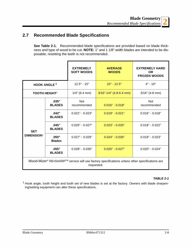
See Table 2-1. Recommended blade specifications are provided based on blade thick-ness and type of wood to be cut. NOTE: 1” and 1 1/8” width blades are intended to be dis-posable; resetting the teeth is not recommended.
EXTREMELY SOFT WOODS
AVERAGEWOODS
EXTREMELY HARD OR
FROZEN WOODS
HOOK ANGLE 1
1 Hook angle, tooth height and tooth set of new blades is set at the factory. Owners with blade sharpen-ing/setting equipment can alter these specifications.
12.5° - 15° 10° - 12.5° 4° - 10°
TOOTH HEIGHT1 1/4" (6.4 mm) 3/16"-1/4” (4.8-6.4 mm) 3/16" (4.8 mm)
SETDIMENSION1
.035" BLADES
Notrecommended 0.016" - 0.018"
Notrecommended
.042" BLADES
0.021" - 0.023" 0.019" - 0.021" 0.016" - 0.018"
.045" BLADES
0.025" - 0.027" 0.023" - 0.025" 0.018" - 0.022"
.050”Blades
0.027” - 0.029” 0.024” - 0.026” 0.019” - 0.023”
.055" BLADES
0.028" - 0.030" 0.025" - 0.027" 0.020" - 0.024"
Wood-Mizer® RE•SHARPTM service will use factory specifications unless other specifications are requested.
TABLE 2-1

Blade Maintenance3
SECTION 3 BLADE MAINTENANCECustomers have two options regarding maintenance of their blades: Use theWood-Mizer® Re-Sharp service or purchase the optional blade sharpener and toothsetterto maintain your own blades.
Using Wood-Mizer’s Re-Sharp service is recommended. Using the Re-Sharp service isless expensive for most customers than sharpening and setting the blades themselves.Inspections by qualified Re-Sharp technicians ensure that proper blade geometry ismaintained.
3.1 General Blade Maintenance Information
As you use a blade, the teeth of the blade slice away pieces of wood that they contactand carry these pieces in the form of sawdust out the other side of the log.
See Figure 3-1. As the teeth contact the wood (or anything else in their path, such as dirt)the friction begins to wear the teeth down. Specifically, it is the outside corners of the setteeth that wear first.
When these corners become round and shiny, it results in a "dull" blade. Dirt, rocks, sandand other foreign materials that may be in the log will wear the teeth considerably fasterthan the wood you are cutting. Such materials should be removed from the path of theblade (especially the side the blade enters) before you start cutting.
When the tips start to become round and shiny, the blade can not cut as fast as when thetips were sharp and still maintain a straight cut. The wood will not chip away as quickly
FIG. 3-1
Kerf
Blade entersthe wood
Sawdust is airbornein gullet and exits wood(see detail)
The tip of the toothcuts (shaves) the wood
SM0282
3-1 BMdoc071312 Blade Maintenance
Blade Maintenance 3
and the blade will be forced to move up or down, resulting in a wavy cut.Cutting with a dull blade will also do the following:
Reduce blade life because cutting speeds are slow.
Slow cutting speeds use more flex life. Flex life is the total number of times ablade will bend around the blade wheels before breaking. A smaller, or thinner,piece of steel will flex, or bend, more than a thick piece of steel. The thin ribbon ofsteel that Wood-Mizer® uses to produce their blade is well suited for the task of bothsupporting the teeth and bending around the wheels.
Cause lower production output due to slower feed rates.
Make the blade harder to sharpen, requiring more passes on the sharpener toregain a sharp tip.
Cause more wear on the grinding wheel.
Force the blade against the blade guide flange, causing cracks in the back edgeand gullet of the blade to form quicker.
To regain a sharp tip on the teeth, you must grind the face and back of the tooth until thetip is square again.
NOTE: Before you resharpen the blade, check it for cracks. Most cracks occur across theband of the blade at the lowest point of the gullet. If you find any cracks, do not resharpenthe blade. Install a new blade. To reduce the risk of premature blade fatigue from hairlinecracks, it is important to thoroughly clean the gullet of cracks during resharpening. It maybe necessary to lightly grind the blade twice (using a light face, back and gullet grind eachtime) to thoroughly clear the gullet cracks.
Also, the amount of material you have to grind from the teeth will depend on how roundedthe teeth are. If a heavy amount must be removed to regain a sharp tip, it is best to grindthe blade lightly twice, rather than grind heavily once.
Tooth height is controlled by how much material you grind from the gullet. For recom-mended tooth heights for varying cutting applications, See TABLE 2-1.
When grinding material from the back of the tooth, the amount of material bent out fromthe blade becomes smaller. On average, 2 to 3 thousandths set is lost from each side ofthe blade when it is sharpened. The teeth must be bent back out when the set falls belowrecommended specifications.
Sharpening leaves tiny metal burrs on the back side of the teeth. New blades also have
Blade Maintenance BMdoc071312 3-2

Blade Maintenance3
burrs. These burrs MUST be removed before the set is checked. If they are not removed,they may cause false readings. To remove the burrs: cut with the blade, or invert theblade so that the inside faces out and drag a stick of hardwood across the blade in theopposite direction that the teeth cut. (Use the weld in the blade as a reference point forstarting and stopping.) Re-invert the blade before measuring set or cutting.3-3 BMdoc071312 Blade Maintenance

Blade MaintenanceBlade Life Expectancy 3
3.2 Blade Life Expectancy
We have identified several areas that greatly affect overall blade performance. Each itemlisted below contributes to the service life of a blade. These items are not listed in anyorder of importance. Careful attention to each of these areas will help each Wood-Mizer®
blade achieve maximum performance and life.
Sawyer Capability The sawyer has control of many of the cutting conditions that affect the blade. Hemust carefully monitor wood cleanliness, blade tension, feed rate, blade guide posi-tion and alignment, drive belt tension, etc. to cut as fast as possible while still main-taining a straight cut.
Log DiameterSmaller logs have value and can be cut at a faster rate of speed, but will use moreflex life to produce the same volume of wood as a larger log. Logs ranging from 18"to 36" in diameter will increase the total board feet a blade can produce.
Wood SpeciesAll trees vary in density. Softwoods have inconsistent densities (growth rings, knots)and require careful monitoring of feed speeds. Hardwoods usually have a more con-sistent density (except in very low grade logs) and will allow faster and steadier cut-ting speeds. Some examples of wood densities include:
Extremely Soft (Balsam, Aspen, Cotton Wood, Basswood)Medium to Hard (Red Oak, Yellow Poplar, Most Pines, Walnut, Cherry, Gum)Extremely Hard (White Oak, Osage Orange, White Ash, Hickory, Sugar Maple,Barn Beams)
Moisture ContentWood density changes as the log dries, requiring different cutting speeds. In somespecies, an extremely soft wood that has dried will cut like an extremely hard wood.Dry wood is more abrasive, too, causing the blade to dull more quickly.
Wood CleanlinessDirt, rocks, sand and other foreign materials that may be in the log will wear theteeth considerably faster than the wood you are cutting. Dull blades require slowercutting speeds and lead to earlier blade breakage.
Blade TensionProper tension is critical for maximum blade performance and cutting speeds.Remove blade tension when the mill is not in use.
Blade Maintenance BMdoc071312 3-4

Blade MaintenanceBlade Life Expectancy3
Blade Wheel BeltsThe blade wheel belts must be in good condition. Worn belts (less than 1/32” of aninch clearance), can allow the blade to contact the metal blade wheel, resulting inearly blade breakage.
The belts also must be of uniform thickness. Non-uniform belt thickness causesadditional stress to a blade resulting in mill vibration and reduced blade life. To pro-mote uniform thickness, keep the belts free from sawdust buildup. Use only Good-year, Dayco Super II, or Browning belts.
Feed RateFeed rates should be as fast as possible while still maintaining a straight cut. Cut-ting at slower speeds reduces overall blade life.
Blade Guide PositionThe blade guides must be positively aligned to provide blade stability and allowmaximum cutting speeds. If the blade guides are tipped upward or downward, theywill cause the blade to cut in the same direction. The blade guide flange or backguide should be adjusted so the blade does not continually run against it.
LubricationUsing the LubeMizer lubrication system will reduce friction and heating of the blade,increasing its overall life.
Drive Belt TensionA loose drive belt will cause the blade to slip and vibrate resulting in early bladebreakage.
MaintenanceImproper blade maintenance will affect blade life. A blade gullet that is not smoothallows stess fractures to occur and cause blades to break prematurely. Sawing withblades that are not maintained for best possible cutting performance causes slowfeed rates which waste overall blade life.
3-5 BMdoc071312 Blade Maintenance

Blade MaintenanceBlade Life Expectancy 3
See Table 3-1. The average blade life between sharpenings and life before a bladebreaks is shown below. Estimates are based on cutting clean logs on a properly alignedsawmill. Remember that overall blade life is measured in the total number of board feetthat a single blade can produce. The averages listed are based on reports from our cus-tomers with portable sawmills equipped with 19” diameter blade wheels. They are basedon actual production, not on a scaled total. Overall blade life is subject to proper blademaintenance.
Blade Average Life perSharpening
Expected Average Overall Life
.035" x 7/8" x 1 1/4" 300-500 board feet 3000 board feet
.042" x 7/8" x 1 1/4".042” x 7/8” x 2”
500-700 board feet 2000-2500 board feet
.045" x 7/8" x 1 1/4"*.045" x 7/8" x 1 1/2".050” x 7/8” x 1 1/2”
800-1000 board feet 2500 board feet
.055" x 7/8" x 1 1/4"*.055" x 7/8" x 1 1/2".055” x 7/8” x 1 3/4”
.055” x 7/8” x 2”
1000-1200 board feet 3000 board feet
* Includes blades with 4°, 9°, 10° and 13° hook angle
TABLE 3-1
Blade Maintenance BMdoc071312 3-6

Blade MaintenanceAutomatic Blade Sharpener Option3
3-7 BMdoc071312 Blade Maintenance
3.3 Automatic Blade Sharpener Option
See Figure 3-2. Wood-Mizer’s Automatic Blade Sharpener (LTAGA) quickly and preciselysharpens the teeth of bandsaw blades.
Adjustments can be made to control the material ground from the face, gullet, and back ofeach tooth. The automatic index allows the operator to load a blade, make the desiredadjustments, and turn the sharpener on. The sharpener will move the blade around togrind each tooth automatically.
Use of the Clamp Alignment tool is important to keep the clamp correctly positioned togrind the face at 90°.
The Automatic Blade Sharpener comes complete with stand, coolant pump and tray,mounting hardware, control box, and magnetic shutoff system. Two indexing cams arealso supplied for 10/30 and 9/29 blade profiles. Other cams are available to enable thesharpener to maintain other blade profiles.
FIG. 3-2
SM0035C
1. Converter On/Off Switch
CoolantPump4. Feed
Rate Dial
5. Grinder On/Off Switch
2. Start Switch3. Stop Switch
CamCam Motor
Blade Support
GrindingWheel
9. MagneticShutoff Sensor
6. Coolant Valve
8. Depth/Back GrindAdjustment Knob
7. Face GrindAdjustment Knob
GrinderMotor

Blade MaintenanceToothsetter/Gauge Option
Blade Maintenance BMdoc071312 3-8
33.4 Toothsetter/Gauge Option
See Figure 3-3. The Toothsetter/Gauge Option (LTTSG-C) accurately sets the teeth ofthe blade. Each tooth is measured with a dial indicator and can be reset with the push ofa lever. The manual indexing system allows the operator to set all the teeth on a blade inminutes.
The Toothsetter/Gauge will set the teeth within .001" tolerance to provide faster cuttingspeeds and smoother board surfaces.
FIG. 3-3
TS0007-3
Dial Indicator Right Index Pawl
Left IndexPawl
Blade RestScrews (2)
Setting Point
GaugeFoot
Blade SupportArms (3)
ClampAdjustmentNut
CrankHandle

Blade Handling4
SECTION 4 BLADE HANDLINGThis section covers coiling the blade, uncoiling the blade and inverting the blade.
WARNING! Always wear gloves and eye protection whenhandling bandsaw blades. Keep people away from workarea when coiling or moving blades.
4.1 Coiling The Blade
See Figure 4-1. Raise the blade in front of you, with the teeth pointed upward. (About 1/3to 1/4 of the blade should be between your hands.) Hold your hands about shoulder-widthapart. Place your thumbs on the outside of the blade and your fingers on the inside of theblade. Squeeze the blade inward, making it oval-shaped.
FIG. 4-1
4-1 BMdoc071312 Blade Handling

Blade Handling 4
See Figure 4-2. Keeping your wrists locked in position, turn your forearms upward andinward. (The teeth will rotate inward and the bottom of the blade will rotate outward.)See Figure 4-3. Bring your hands together. The blade will form three loops. Snap the bot-tom loop upward and catch the three-loop coil in your hands.
FIG. 4-2
FIG. 4-3
Blade Handling BMdoc071312 4-2

Blade HandlingUncoiling The Blade4
4.2 Uncoiling The Blade
See Figure 4-4. Take the three-loop coil in your right hand. Place the band against yourpalm with the blade teeth pointing outward toward your fingers. Slide the top loop off andlet drop.
See Figure 4-5. The remaining two loops of the blade will form a cross. Hold this crossedsection out in front of you with the blade teeth pointing toward you. If the right side iscrossed OVER the left, hold the crossed section with your right hand. (If the left side ofthe blade is crossed OVER the right, hold the crossed section with your left hand.)
FIG. 4-4
FIG. 4-5
4-3 BMdoc071312 Blade Handling

Blade HandlingUncoiling The Blade 4
See Figure 4-6. Keeping the blade in its crossed position, take hold of the side crossedUNDER with your other hand. Use your right (or left) hand to hold only the side crossedOVER. Place your thumbs on the top side of the blade. Put your fingers on the under-neath side of the blade.
See Figure 4-7. Hold the blade out and away from you. Slowly move your hands apartwhile rotating your forearms down and outward.
FIG. 4-6
FIG. 4-7
Blade Handling BMdoc071312 4-4
Blade HandlingInverting The Blade4
4.3 Inverting The Blade
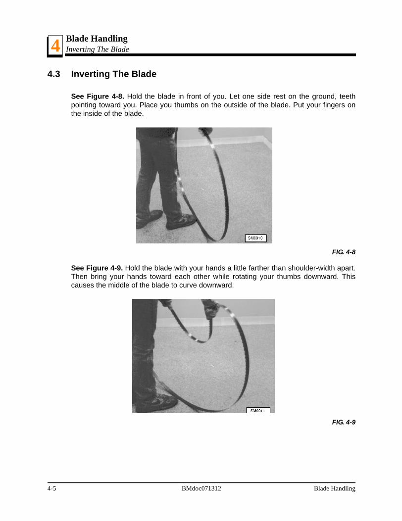
See Figure 4-8. Hold the blade in front of you. Let one side rest on the ground, teethpointing toward you. Place you thumbs on the outside of the blade. Put your fingers onthe inside of the blade.
See Figure 4-9. Hold the blade with your hands a little farther than shoulder-width apart.Then bring your hands toward each other while rotating your thumbs downward. Thiscauses the middle of the blade to curve downward.
FIG. 4-8
FIG. 4-9
4-5 BMdoc071312 Blade Handling

Blade HandlingInverting The Blade 4
See Figure 4-10. Keeping your hands close together, rotate the curved section of theblade up and away from you. The blade will be in an oval shape, but twisted.
See Figure 4-11. Slowly move your hands apart, allowing the blade to untwist.
FIG. 4-10
FIG. 4-11
Blade Handling BMdoc071312 4-6

Blade HandlingStoring Blades4
4-7 BMdoc071312 Blade Handling
4.4 Storing Blades
Use care when moving, storing, or handling blades. When blades are stacked or throwntogether, the tips can be dulled or the set changed.
Stack two blades back-to-back using dividers between each set of blades to prevent theteeth from contacting each other.
If storing blades for long periods of time, be sure the blades are dry then coat with lubri-cant.
Blade HandlingPackaging Blades For Shipping 4
4.5 Packaging Blades For Shipping
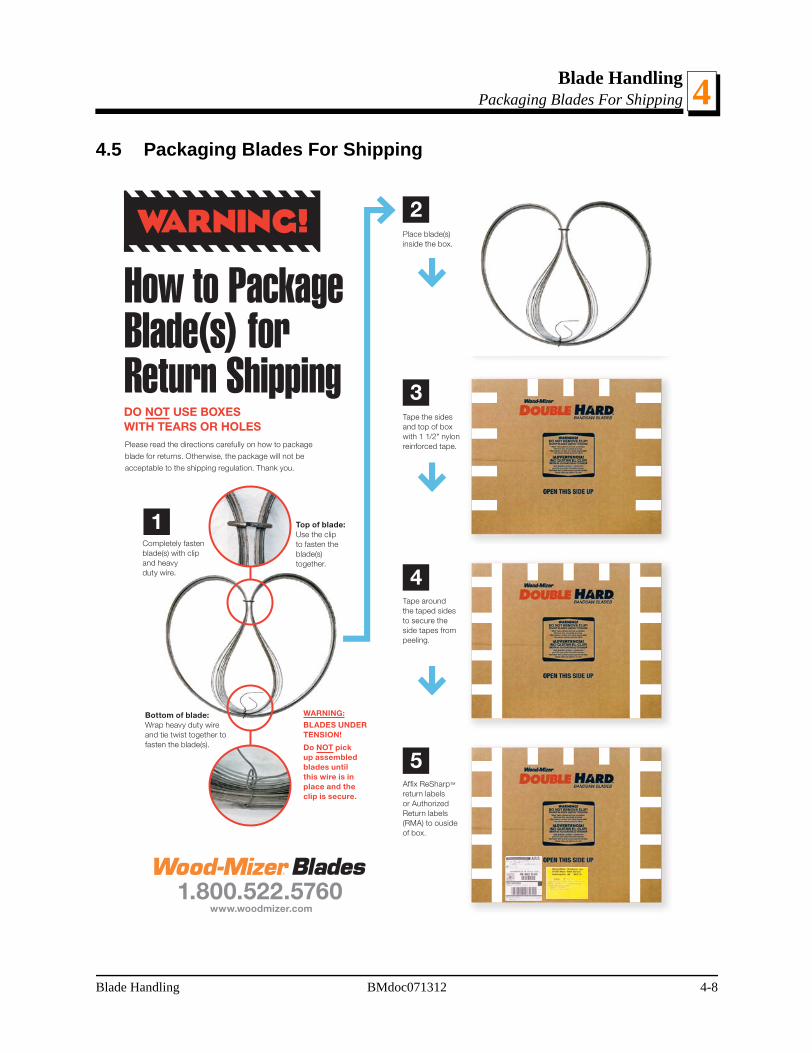
How to Package Blade(s) for Return Shipping
Bottom of blade: Wrap heavy duty wire and tie twist together to fasten the blade(s).
Top of blade: Use the clip to fasten the blade(s) together.
Please read the directions carefully on how to package
blade for returns. Otherwise, the package will not be
acceptable to the shipping regulation. Thank you.
Completely fasten blade(s) with clip and heavy duty wire.
1
Place blade(s) inside the box.
2
Tape the sides and top of box with 1 1/2" nylon reinforced tape.
3
Tape around the taped sides to secure the side tapes from peeling.
4
1.800.522.5760 www.woodmizer.com
DO NOT USE BOXES WITH TEARS OR HOLES
5Affix ReSharp™ return labels or Authorized Return labels (RMA) to ouside of box.
WARNING:
BLADES UNDER TENSION!
Do NOT pick up assembled blades until this wire is in place and the clip is secure.
Blade Handling BMdoc071312 4-8

Blade HandlingPackaging Blades For Shipping4
Returning Broken Blades or WeldsPlease read the directions carefully on how to package
broken weld blade returns. Otherwise, the package will
not be acceptable to the shipping regulation. Thank you.
1.800.522.5760 www.woodmizer.com
Cut approxiately 12" back from
both ends of the blade break.
Make sure to include the section
with the Wood-Mizer code.
Wrap three pieces together with heavy duty wire. Make sure the code number is in front for identification.
Place teeth toward the fold, use double wall cardboard.
12"12"
THIS APPLIES TO BLADE OR WELD BREAKS
STEP 1
STEP 2 STEP 3
Fold cardboard and tape along open side and ends.
STEP 4
STEP 4
Insert blade into thick cardboard envelope and seal.
STEP 5
Apply labels provided by Wood-Mizer.
STEP 6
Retain your tracking number for your record.
WARNING!Failure to follow these guidelines
can result in serious injury.Thank you for your compliance.
1481FlatBoxShippingInst/9/06/wm© 2006 Wood-Mizer Products, Inc.
4-9 BMdoc071312 Blade Handling

TroubleshootingBlade Breakage 5
SECTION 5 TROUBLESHOOTING
Our Resharp blade technicians have spent years evaluating blades sent to us by our cus-tomers. The advice provided in these sections can help you avoid common mistakes andmaximize sawing performance and blade life.
5.1 Blade Breakage
Following is a list of some of the most common preventable causes of premature bladebreakage:
Action Result Solution
Sawing too long with a dull or damaged blade
Stress in the band Change the blade at regular intervals.
Change the blade immediately after striking a foreign object or material.
Flat spots worn on blade guide roller surface
Vibration and heat in blade Replace blade guide rollers as necessary.
Grooves in blade guide roller flange
Damage to back edge of blade Replace blade guide rollers as necessary. Adjust for proper clearance between flange and blade.
Frozen or worn blade guide roller bearings
Heat buidup Lubricate or rebuild roller bear-ings as necessary.
Chipped/broken blade guide wear pads
Damage to blade surface Hone or replace wear pads as necessary.
Misaligned blade guides Damage to blade surface Check blade guide alignment at regular intervals and adjust as necessary.
Blade guide wear pads adjusted too close to blade
Heat on blade surface Adjust wear pads for proper clearance.
Worn blade wheel belts Heat caused by blade contact-ing blade wheel, blade wanders
Replace blade wheel belts.
Loose or damaged drive belts Vibration, blade slippage Adjust or replace drive belts
Sawdust between blade wheel and blade wheel belts
Vibration, blade slippage Inspect blade wheels for saw-dust at regular intervals and remove as necessary.
Improper blade tension Stress in band Regularly check blade tension while sawing and adjust to rec-ommended range as necessary.
Troubleshooting BMdoc071312 5-1

TroubleshootingBlade Breakage5
Dropping a tensioned blade down on a log or cant
Kinks, stretching Replace the blade.
Excessive sap buildup on blade or blade wheel belts
Heat buildup Use waterlube to prevent buildup. Remove blade and clean if necessary. Scrape buildup from belts.
Ramming blade into end of log or other stationary objects
Kinks in blade Replace the blade.
Excessive pitch buildup on sides of the teeth
Heat, wavy cuts Clean or replace blade.
Burning gullet of blade during sharpening
Breakage point Use coolant during grinding.Use multiple passes through sharpener, removing smaller amounts of material each pass.
Large burrs created during sharpening
Breakage point Use coolant during grinding.Use multiple passes through sharpener, removing smaller amounts of material each pass.
Too much or too little hook angle in tooth
Vibration and/or stress in the blade and slow cutting speed
Adjust sharpener to provide proper hook angle for material to be sawn.
Incomplete sharpening of tooth profile
Dull blade, breakage point Sharpen complete profile.
Missing the outside corners (cut-ting tip) of set teeth
Dull blade Sharpen complete profile.
Removing too little material from gullet
Fails to remove stress fractures Adjust sharpener to take more material from gullet of blade.
Worn grinding wheel Steel buildup in wheel reduces its grinding ability
Replace grinding wheel.
Incorrect grinding wheel shape Sharp radius at base of tooth is condusive to stress fractures
Redress grinding wheel with proper profile.
Too much or too little set in blade Vibration and/or stress in the blade and slow cutting speed
Adjust toothsetter to provide proper set for material to be sawn.
Toothsetter setting point strikes tooth too low
Distorts blade body, creating a place for fractures to occur
Adjust toothsetter so setting point contacts tooth properly.
Stored blades allowed to rust Wipe blades dry before storing.
Storing blades without removing sawdust/sap residue
Oxides and acids can cause mircroscopic damage to the blade surface
Clean blade before storing.
5-2 BMdoc071312 Troubleshooting

TroubleshootingBlade Performance
Troubleshooting BMdoc071312 6-1
65.2 Blade Performance
Using the appropriate blade for the species and condition of the wood your sawing is cru-cial to any sawing operation. Using blades with the wrong profile can cause the blade tochatter, too much sawdust, slow feed rates, premature blade breakage and prematuredullness. If the appropriate blade is used, sawing performance problems can usually beattributed to the common causes listed below:
Problem Cause Solution
Wavy cuts Sawing too fast Use slower feed rate.
Sawing too slow (increases sawdust that isn’t cleared from the cut fast enough)
Use faster feed rate.
Undertensioned blade Check and adjust blade tension.
Sawdust or pitch buildup on blade or blade wheels
Clean or replace blade and/or blade wheel belts.
Blade not properly tracked on blade wheels
Check and adjjust blade tracking.
Blade guide misalignment Check and adjust blade guides.
Incorrect drive belt tension Check and adjust drive belts.
Worn/damaged blade wheel belts Replace blade wheel belts.
Worn blade wheel crown (beltless steel blade wheels only)
Replace blade wheels.
Loose or worn blade wheel bearings Replace blade wheel bearings.
Improperly adjusted mast pads Adjust mast pads properly.
Blade not parallel to sawmill bed Align sawhead and bed rails.
Loose blade guide arm Adjust blade guide arm rollers.

TroubleshootingSpecial Problem Wood Types or Conditions5
5.3 Special Problem Wood Types or Conditions
Cutting extremely hard wood
Use the 375 Series (.045 x 1 1/4") or 475 Series (.055 x 1 1/4") blade
Keep set to a minimum - .017" to .019"
Use hook angles between 4° and 10°
After using the blade, measure the set on the tooth setter. If inconsistent, the teethare flexing (bending) while cutting.
Sometimes will require large quantities of lube to keep the blade free of sap buildup.This sap buildup will cause a blade to cut inaccurately and break prematurely.
Cutting hardwoods high in silica
Use bi-metal blades or 4° hook angle blades with lubrication.
Cutting extremely pitchy woods
Will sometimes require a chemical agent to be brushed orsprayed on the blade periodically. (Wood-Mizer lube, liq-uid soap, vegetable oil and Pine Sol are popular.)
WARNING! Use ONLY water, Wood-Mizer Lube Additive orwindshield washer fluid with the water lube accessory.Never use flammable fuels or liquids such as diesel fuel. Ifthese types of liquids are necessary to clean the blade,remove it and clean with a rag. Failure to do so can dam-age the equipment and may result in serious injury ordeath.
Cutting extremely dry wood
Use no water. If water is necessary, use as little as possible because water willcause the wood to swell. You can also try using water between cuts to clean theblade and shutoff the water while making the cut.
5-2 BMdoc071312 Troubleshooting

TroubleshootingSpecial Problem Wood Types or Conditions 5
Cutting varied density softwood
Add more hook angle to the blade
Sharpen so the teeth are a minimum 1/4" tall.
Use .050" or .055" thick blades.
Troubleshooting BMdoc071312 5-3

i BMdoc071312 Index
B
blade geometry 2-1face angle 2-6hook angle 2-5recommended blade specifications 2-8tooth height 2-4tooth set 2-7
blade handling 4-1coiling the blade 4-1inverting the blade 4-5package for shipping 4-8storing blades 4-7uncoiling the blade 4-3
blade introduction 1-1which blade to use 1-3Wood-Mizer blades 1-2
blade maintenance 3-1blade life 3-4general information 3-1sharpener 3-7toothsetter 3-8
S
specificationsrecommended blade 2-8
T
troubleshooting 5-1blade breakage 5-1blade performance 6-1special conditions/wood types 6-2
INDEX


