MiUT 3? - NASA STUDY OF MICROSTRUCTURAL CHARACTERISTICS OF NI-BASED SUPERALLOYS AT HIGH TEMPERATURES...
67
N A G %- 0-7(o FINAL TECHNICAL REPORT A STUDY OF MICROSTRUCTURAL CHARACTERISTICS OF NI-BASED SUPERALLOYS AT HIGH TEMPERATURES Submitted to P7 NATIONAL AERONAUTICS AND SPACE ADMINISTRATION ri WASHINGTON, D.0 Department of Physics Alabama Agricultural and Mechanical University P0. Box 428 Normal, Alabama 35762 December 1990 -- 1fui) .Tu Y LCINULIUKAL MHt'ISTICS AJiBASE0 SUPERALLOYS AT HIGH TEMPERATURES Final Report (Alabama Agricultural and Mechanical Coll.) 67 p Unclas CSCL hF G3126 0012364 https://ntrs.nasa.gov/search.jsp?R=19910013119 2018-06-30T09:33:04+00:00Z
Transcript of MiUT 3? - NASA STUDY OF MICROSTRUCTURAL CHARACTERISTICS OF NI-BASED SUPERALLOYS AT HIGH TEMPERATURES...

N A G %- 0-7(o
FINAL TECHNICAL REPORT
A STUDY OF MICROSTRUCTURAL CHARACTERISTICS OF NI-BASED
SUPERALLOYS AT HIGH TEMPERATURES
Submitted to
P7 NATIONAL AERONAUTICS AND SPACE ADMINISTRATION ri
WASHINGTON, D.0
Department of Physics
Alabama Agricultural and Mechanical University P0. Box 428
Normal, Alabama 35762
December 1990
-- 1fui) .Tu Y LCINULIUKAL
MHt'ISTICS AJiBASE0 SUPERALLOYS AT
HIGH TEMPERATURES Final Report (Alabama Agricultural and Mechanical Coll.) 67 p Unclas
CSCL hF G3126 0012364
https://ntrs.nasa.gov/search.jsp?R=19910013119 2018-06-30T09:33:04+00:00Z
I
FINAL TECHNICAL REPORT
ON UMPAMN
NASA GRANT NAG8-076
A Study of Microstructural Characteristics of Ni-Based Superalloys at High Temperatures
Principal Investigator : Ravindra B. Lai Professor of Physics Alabama A and M University Normal, Al 35762 Tel No. (205) 851-5309
Co-Investigator : M.D.Aggarwal Associate Professor of Physics Department of Physics Tel No. (205) 851-5308
Submitted to
National Aeronautics and Space Administration George C. Marshall Space Flight Center Marshall Space Flight Center, Al 35812
December, 1990
smim* COWYAIR$
Report No. AAMU-NAG-003

MiUT 3?
4
TABLE OF CONTENTS
PREFACE (i)
SUMMARY (ill)
1. Introduction 1
1.1 Technical Background 1
1.2 Objectives of the Project 4
2. Experimental Techniques and results 5
2.1 Sample Preparation 5 (cutting/grinding/polishing)
2.2 Etching/Microstructure Development 8
2.3 Photomicrography 9
2.4 Differential Thermal Analysis treatment of superalloys
2.5 Approximate method of predict range of superalloys
3. Publications and reports relating
and heat20
ing solidification 45
to this project54
References 55
Appendix A 56
Weight percent composition of various elements in Nickel based superalloys
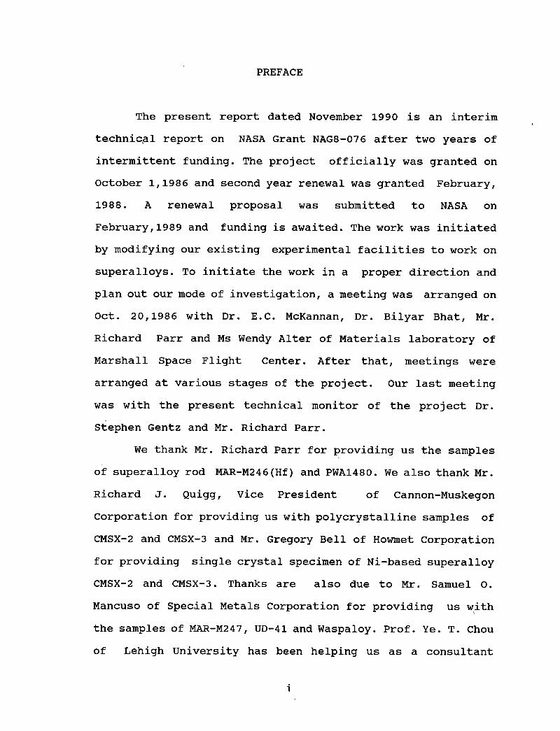
PREFACE
The present report dated November 1990 is an interim
technical report on NASA Grant NAG8-076 after two years of
intermittent funding. The project officially was granted on
October 1,1986 and second year renewal was granted February,
1988. A renewal proposal was submitted to NASA on
February,1989 and funding is awaited. The work was initiated
by modifying our existing experimental facilities to work on
superalloys. To initiate the work in a proper direction and
plan out our mode of investigation, a meeting was arranged on
Oct. 20,1986 with Dr. E.C. McKannan, Dr. Bilyar Bhat, Mr.
Richard Parr and Ms Wendy Alter of Materials laboratory of
Marshall Space Flight Center. After that, meetings were
arranged at various stages of the project. Our last meeting
was with the present technical monitor of the project Dr.
Stephen Gentz and Mr. Richard Parr.
We thank Mr. Richard Parr for providing us the samples
of superalloy rod MAR-M246(Hf) and PWA1480. We also thank Mr.
Richard J. Quigg, Vice President of Cannon-Muskegon
Corporation for providing us with polycrystalline samples of
CMSX-2 and CMSX-3 and Mr. Gregory Bell of Howinet Corporation
for providing single crystal specimen of Ni-based superalloy
CMSX-2 and CMSX-3. Thanks are also due to Mr. Samuel 0.
Mancuso of Special Metals Corporation for providing us with
the samples of MAR-M247, UD-41 and Waspaloy. Prof. Ye. T. Chou
of Lehigh University has been helping us as a consultant
1

during the progress of the project. Mr. Samuel Oyekenu worked
as a graduate student on the project.
11
Summary
The objective of this investigation is to study the
microstructural characteristics of the Ni-based superalloy
MAR-M246(Hf) which is used in manufacturing the components of
the Space Shuttle's main engine/. , These superalloys need
optimum heat treatment to get the best results. To find out
the optimum heat treatment the techniques of differential
thermal analysis (DTA) and the optical photomicrographs were
utilized. In the first phase, the existing experimental
equipment like cutting, grinding/polishing machines and
inetalliurgical microscope have been set up to cut/polish and
take the photomicrographs. In the beginning of the project a
Perkin Elmer differential thermal analyzer DTA1700 alongwith
temperature programmer and the needed computer interface was
procured and made operational. In the second year Leitz
Metallux-3 hot stage research microscope has also been
procured and installed for in-situ observation of the
superalloy samples.The hot stage when tested for the first
time alloyed the thermocouple with the Tantalum heating
element and has now been installed finally by the supplier.
Samples of MAR-M246(Hf), MAR-M247, Waspaloy, tfdimet-41,
CMSX-2 and CMSX-3 (polycrystalline and single crystals) have
been studied using differential thermal analyzer and the
results are reported here. Photomicrographs of the Ni-based

superalloy MAR-M246(Hf) has been recorded before and after
heat treatment at certain temperatures. More heat treatments
need to be done before a final inference can be arrived at.
iv
1. INTRODUCTION
1.1 Technical Background
Superalloys are an important class of materials and
have made much of our very high temperature engineering
technology possible.They are complex materials capable of
maintaining certain of their room temperature physical and
mechanical properties at elevated temperatures. Superalloys
can be divided in three broad classes : Nickel base
superalloys, cobalt base superalloys and iron base
superalloys. Iron generally disappeared as an alloy base in
favor of nickel and cobalt since they stabilized the stronger
FCC structure. Mechanical properties such as strength,
ductility, toughness of metals and alloys are strongly
dependent on their type of structure. Hexagonal close packed
metals commonly have less strength than the fcc and bcc
metals. Because of the packing arrangement, their ductility is
more dependent on direction than f cc and bcc metals. Nickel
based superalloys have found widespread applications because
of their corrosion resistance, high strength and the
capability of maintaining their room temperature physical and
mechanical properties at elevated temperatures. Essentially a
superalloy can be considered as a "chemical stew" containing
as much as 14 different elements'. Nickel is an ideal base
for such alloys because of its high melting point 1453 C
(2647F), adequate corrosion resistance and ability to dissolve
a number of other metallic elements which serve to strengthen
1

it. In the present investigation, nickel base superalloy
manufactured by Martin Marietta MAR- M246(Hf) has been
selected which is used in fabricating components for the
space shuttle main engine. This is a directionally solidified
material with the weight composition as follows:
Ni 58.035% Hf 1.75%
Co 10% Ti 1.5%
W 10% Ta 1.5%
Cr 9% C 0.15%
Al 5.5% Zr 0.05%
Mo 2.5% B 0.015%
The different elements go into the solid solution to
provide one or more of the following effects:
Strength Mo,Ta,W
Oxidation Resistance Cr, Al
Phase Stability Ni
Gamma Prime Al, Ti /
The j phase is the key factor responsible for the
extraordinary useful high temperature properties of Ni-based
superalloys and has a complex ordered structure which
precipitates coherently with the matrix to provide
precipitate hardening. The major phases present in the
microstructure of these nickel superalloys' are gamma matrix
(y) the internietallic precipitate gamma prime (y), carbides
like MC, M23C6 and M6C. M6C and M23C6 tend to populate the
2
grain boundaries. In addition, constituents such as sigma
(a), mu (j) and Laves phases are found in Ni based
superalloys.
The observation of polished and etched samples under an
optical microscope is one of the most useful and easily
applied technique for establishing the microstructure of
superalloys. However, as with any visual technique it depends
critically upon the sampling procedure selected since the
region viewed represents only a small fraction of the total
volume of the material. Since sample selection is such an
important stage in any inicrostructural evaluation it must be
undertaken to ensure that all necessary and appropriate
information will be observed. Indeed it is often desirable to
select samples not only from different regions of the whole
but also at various angles. Samples are prepared by a
mechanical lapping sequence followed, in certain special
circumstances, by final chemical polishing to remove the
"flowed" surface layer.
3

1.2 Objectives of the Project
1. To determine the heat treatment/annealing recipe for the
superalloy MAR-M246(Hf) to improve its high temperature
performance.
2. To correlate the mechanical properties of Ni-based
superalloy MAR-M246(Hf) with structure by systematic
study of optical photomicrographs and DTA curves on
various heat treated samples.
3. To study other superalloys and compare its behaviour with
Ni-based superalloy MAR-M246(Hf).
4
2. EXPERIMENTAL TECHNIQUES
2.1 Sample Preparation
Ni-based superalloy MAR-M246(Hf) samples were
provided by Mr. Richard Parr of Marshall Space Flight Center,
Huntsville. Samples of other Ni-superalloys viz., MAR-M247,
Waspaloy and Udiiuet (TJD-41) were provided by Mr. Samuel 0.
Mancuso of Special Metals and polycrystalline samples were
provided by Mr. Richard J. Quigg of Cannon-Muskegon
corporation and single crystal specimen were supplied by Mr.
Gregory Bell of Howmet Corporation.
Samples of MAR-M246(Hf) were cut using low speed diamond
saw which took 3 to 4 hours to cut a 3/8 inch diameter rod of
the directionally solidified material. The purpose of cutting
is to reduce the specimen to a manageable size and to reach
the desired plane for observation. The samples were cut
parallel, perpendicular and at 45 degree a'ngle to the major
axis of the rod. The samples need to have a highly polished
surface to reveal the microstructure. To accomplish this,
these samples were then embedded in the cold mold using
Buehler Castoglass resin and hardener as well as in hot mold
which provides a means of holding the specimen during
preparation. The cold mold can be dissolved in "Stripsolve"
to take the sample out of the mold for later heat treatment
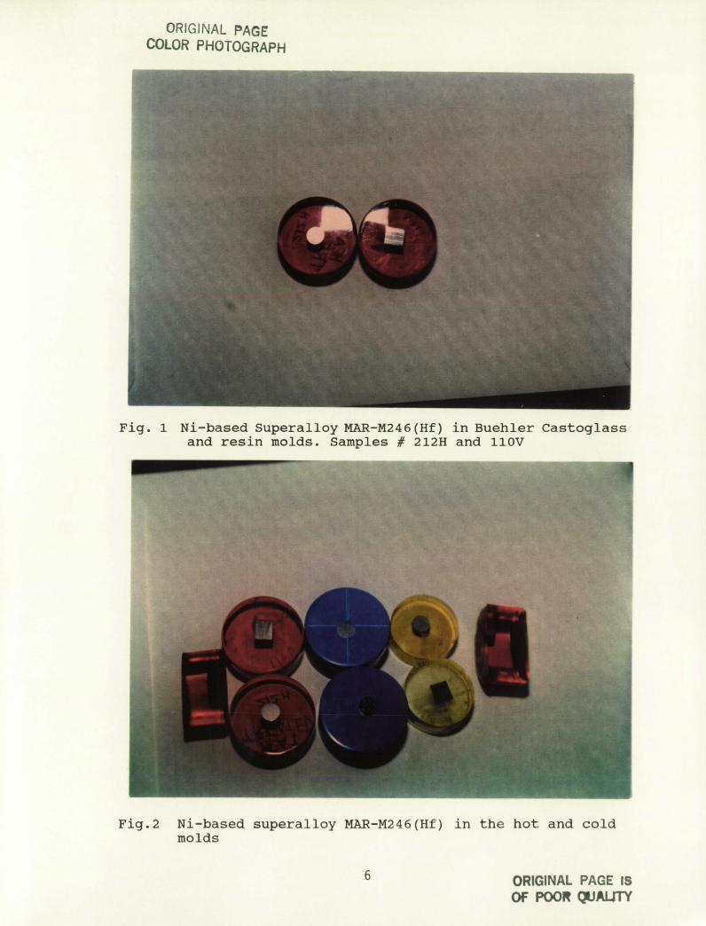
or other processing. Pictures of some of the samples in the
mold are shown in Figs 1 to 2. Fine grinding reduces the
5
ORIGINAL PAGE COLOR PHOTOGRAPH
Fig. 1 Ni-based Superalloy MAR-M246(Hf) in Buehler Castoglass and resin molds. Samples # 212H and 110V
I
Fig.2 Ni-based superalloy MAR-M246(Hf) in the hot and cold molds
6 ORIGINAL PAGE Is OF POOR QUAUTY

deformation level of the specimen surface, preparatory to
rough and final polishing. The specimen is grinded on a
series of abrasive papers usually 240,320,400 and 600 grit
lubricated with water.
Fine grinding is accomplished by using a motor driven
polisher/grinder. Rough and final polishing are critical
steps, which more than any other steps, determine the success
or failure of specimen preparation. Rough polishing is
performed on a low nap cloth that has been charged with 6
micron Metadi polishing compound. This step is important
because it must remove the fine grinding scratches while
maintaining a flat surface. In Ni-based superalloys, samples
are prone to deformation during abrasive preparation and
these deformation layers tend to obscure incompletely removed
grinding scratches. These scratches have a way of reappearing
when the finished polished specimens are etched to reveal the
microstructure. The best way to avoid this problem is to
perform each step thoroughly as though it was the most
important one2'3.
Final cloth polishing is usually performed with 1
micron, 0.3 micron and .05 micron alumina on different
microcloths respectively. The purpose of this step is to
remove the final traces of scratches and provide the highly
polished surface needed to reveal the microstructure.
7

2.2 Microstructure Development
To prepare the samples for revealing the microstructures,
samples are etched using various etchants. It was found better
to etch lightly at first, then remove the first light etch by
returning briefly to the final polishing step. By polishing
off the first etch applied, then reetching, any remaining
fine residual scratches are usually removed. The second etch
produces sharper, well defined microstructural detail. The
etchants which are used are listed below:
1. Kalling's Reagent # 1 5g CuCl
100 ml Hydrochloric
Acid
100 ml Ethanol
40 ml Distilled water
2. Kalling's Reagent 5g Cud2
100 ml Hydrochloric
Acid
100 ml Ethanol
3. Etchant for Gamma prime 50 ml Hydrochloric
Acid
1-2 ml H202(30%)
8

4. Carbides
100 ml. Ethanol 1-3 ml Selenic Acid
20-30 ml Hydrochloric
Acid
2.3 Photomicrography
When we examine the microstructure of a material we are
looking at very small sample of the structure. From this
limited view we have tried to understand how the properties
of the material relate to the structure. But when we measure
the properties of the material, such as tensile strength,
hardness, density etc. we use a much larger specimen, so that
the measured properties refer to something hundreds or
thousands of times larger than our microscopic view. It
should not be surprising, therefore, that it is difficult to
establish true correlations between properties and
inicrostructure.
In the previous year, we had been using the existing
Olympus inverted metallurgical microscope model PME with 35
mm camera attachment. This year Leitz Metallux 3 microscope
with a heating stage upto 1750 C is being procured for
in-situ observation of the phase changes. This instrument
will allow us to heat the sample in vacuum or in inert argon
atmosphere upto 1750 C. The sample is placed on a heating
band made out of tantalum or tungsten which are heated by
means of low voltage high current flowing through them. The
9

heating elements and the interior of the chamber are covered
by a radiation protection plate. Only the surface of the
sample remain visible through a small observation window.
Olympus microscope has been used for most of this study
and the various photomicrographs attached herewith are for
MAR-M246(Hf) before and after heat treatment. Various
locations show y , MC, N23C6 on these photographs. The new
microscope with hot stage is completely installed and in
operational and we have been able to make in situ observation
of different phases at high temperature through the
microscope.
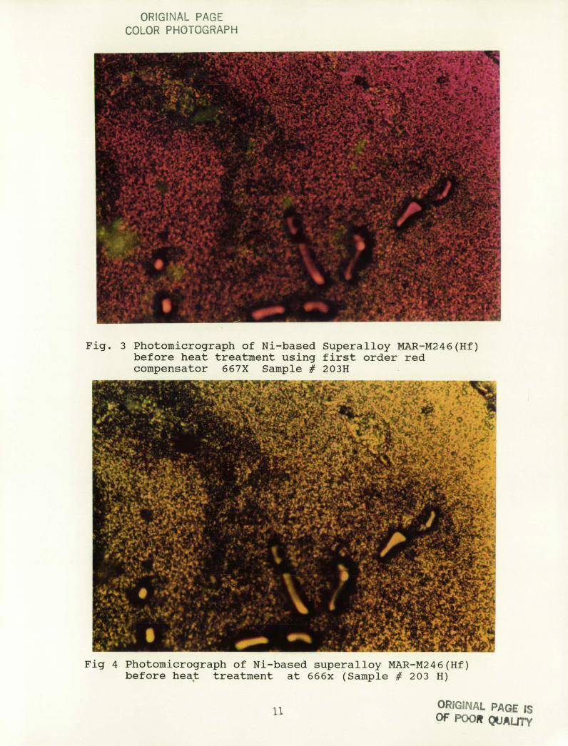
Photomicrographs are taken using the Leitz metallux-3
microscope using first order red compensator between the
polarizer and analyzer on samples of Ni-based superalloy MAR-
N246(Hf) after polishing and etching. A sample cut
perpendicular to the major axis of the rod is suffixed by an
ItH it and the sample cut along the major axis is suffixed by an
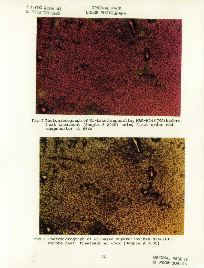
"V". Photomicrographs (Fig Nos. 3 to 6) are shown for sample
# 203H before annealing with or without the first order red
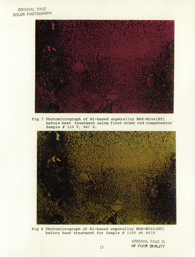
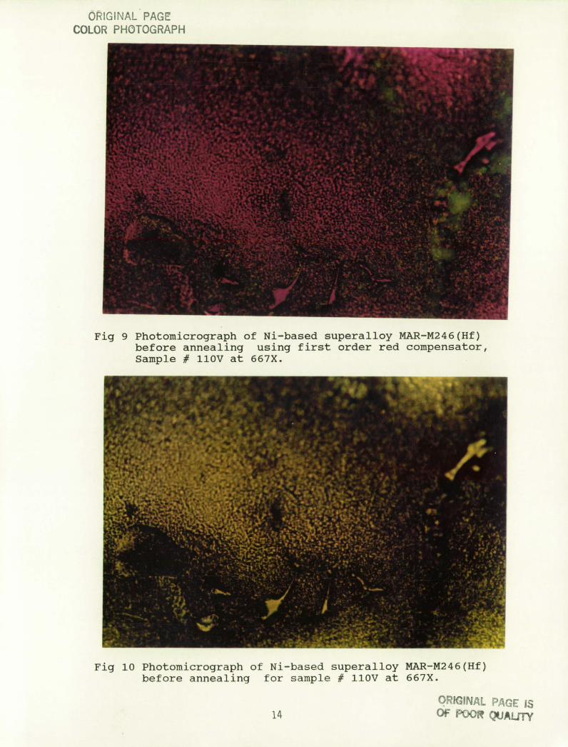
compensator. Similarly photomicrographs Nos 7 to 10 are shown
for sample # 110V with or without first order red
compensator.
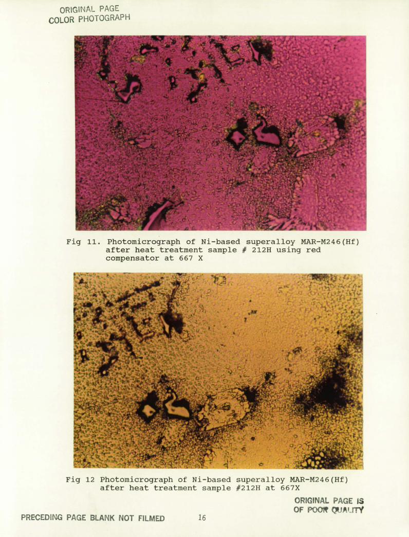
An annealed/heat treated sample (1220 + 6 C for 2 hours
and 871 + 14 C for 8 hours) was cut perpendicular and
parallel to the major axis of a 3/8 inch diameter rod of
10
'3T • •' •,. s • .
b.
'2" :T• • 4%I •. — p,0
ORIGINAL PAGE
COLOR PHOTOGRAPH
•.:-.;
..W. ..q. • •'
• j. a. 4j . ...: .1Q1r'C.. 2
of
I.ti' W•;'
e
%. . •I# '• a'
Fig. 3 Photomicrograph of Ni-based Superalloy MAR-M246(Hf) before heat treatment using first order red compensator 667X Sample # 203H
.I'
.'
'4
Fig 4 Photomicrograph of Ni-based superalloy MAR-M246(Hf) before heat treatment at 666x (Sample # 203 H)
OR1G;NAL PAGE IS 11
OF POOR (JALI1y
ORIGINAL PAGE
COLOR PHOTOGRAPH
to 4
c .'...::
,. IV I P- •:¼c4
Fig.5 Photomicrograph of Ni-based superailoy MAR-M24u(flt)betore heat treatment (Sample # 203H) using first order red compensator at 666x
I
or
4 U
•LiT') .' ...
Fig 6 Photomicrograph of Ni -based supora 11 o f1-r.:4 (Ill before heat treatment at 666x (Sample # 203H)
12ORIC!1AL PAGE Is
OF POOR Q(JALrry
. . e •
• SlIIIIIIIMI ' .j I —
h 1 . •
ORIGINAL PAGE COLOR PHOTOGRAPH
Fig 7 Photomicrograph of Ni-based superalloy MAR-M246(Hf) before heat treatment using first order red compensator
110 V, 67 X.
Fig 8 Photomicrograph of Ni-based superalloy MAR-M246(Hf) before heat treatment for Sample # 110V at 667X
OCWAL PAGE IS
13 OF POOR QUALiTY
Jua p • • I • I.. •.••. .••t p .. '(3
AV
P?
rot
• V -
-- .. :#a'?' - • ..-••-
4-.
• I •_•I•%_ •';•:
t I '.... --4
.': •iiL• •.?ti:/•..
t' . . -
t!t(
-
±-
eQl
tit
• 5__S• . .•.,
2: J
5;.
• : -, •..,. .• S -
5, . *
• • _ i:;- .
S...,..5
I i:tA., I
fw-r -5.içq -w-
7
• -y 4S - S
,• ' ctt
ORIGINAL PAGE
COLOR PHOTOGRAPH
, 4.
I;. 1'
t tb ,
,
': c
!
AV
::•.' .• ;7)•1• .1 '- .. - qL-. .)t)A5
a - .. I 't r •-•5
.. 5)55) •.•
,I,••• . . S j._'P! •- t - -
•- .,, . -:-- ..• ..t.i___ 4 t •c, -•
-••,• . . -
.5
L-- E
S.
Fig 11. Photomicrograph of Ni-based superalloy MAR-M246(Hf) after heat treatment sample # 212H using red compensator at 667 X
.5
,1•-• S...-,.
.);lj f#•5S
oil
i.
I
Fig 12 Photomicrograph of Ni-based superalloy MAR-M246(Hf) after heat treatment sample #212H at 667X
ORIGINAL PAGE IS OF POOR JAUTY
PRECEDING PAGE BLANK NOT FILMED 16
,fl •
•.:
-, • •-:
,, 11 vJ I
ORIGINAL PAGE
COLOR PHOTOGRAPH
,.-- - t.?r ?-.'-- ,. -I-
lc'
• -. .• .•
It-
Af k.4
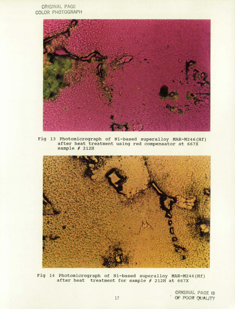
Fig 13 Photomicrograph of Ni-based superalloy MAR-M246(Hf) after heat treatment using red compensator at 667X sample # 212H
a
it
AV
•,••
•. •!qr;i1 •'
..i.. ii..•.
1 •. .l •• •
- . • .. 'r''-
2 • do rw ...
r. ,. .:i' - • •-
çi•'--. • -
:- "--I
:-
,•'. _•,_. -.- I'-. -. -,
Fig 14 Photomicrograph of Ni-based superalloy MAR-N246(Hf) after heat treatment for sample # 21211 at 667X
-.. •-r i' £-' Ip- • ,. *
,-' N.
S; c_.
ORIGINAL PAGE IS 17 OF POOR QUALJTY

'- . ..
ORIGINAL PAGE COLOR PHOTOGRAPH
Fig 15 Photomicrograph of Ni-based superalloy MAR-M246(Hf) after heat treatment for sample # 213V at 667X.
: - - ç .w,
S . p •• Y i
•1 ••• .'• •,
" ,'•. 4
;J'i%*•:, -
I c 0
'p. .. • ' % l' •: -:- - - • -P... ••'' :.. -
•• .•. •.. - .- - ,T- ? - k • 1;•- .. -- '. .'...' ..- -. . . , • •,_.:F.,I- •' . . • .- -
• -:'•-. •- .I .:--,. a _ -, - • 10 Ile •. :r.---r. - . b .
Ii .•.)' _* •
II
'i.; 'c'-
c-.l1 ?
Fig 16 Photomicrograph of Ni-based superalloy MAR-M246(Hf) after heat treatment for sample # 213V at 667X
18 ORIGINAL PAGE IS OF POOR QUALiTY
ORIGINAL PAGE COLOR PHOTOGRAPH
: ; • t• -''?: S -
• 1 •
•1 i It
yS _i\'i',.k , • tit- • ' 4Tp3.4 4I.'1 •:'
s\r't
f&., : ":.:. ••. -.
tr.' f
:•.
•'''
IJW
4.. .. •.
-I'-. . s .•-'
-
IY
4
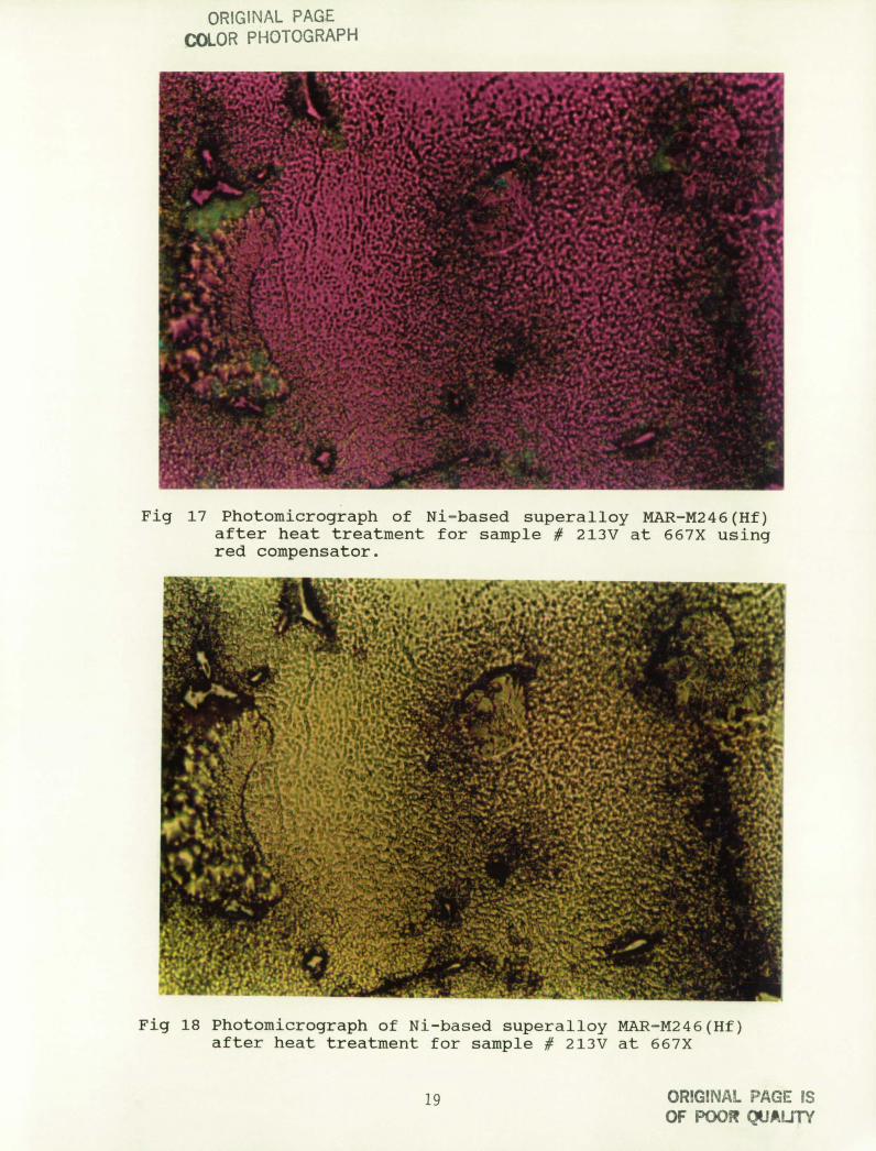
Fig 17 Photomicrograph of Ni-based superalloy MAR-M246(Hf) after heat treatment for sample # 213V at 667X using red compensator.
.% . •445
I ••
7 5- • 4 '4 ;4
.J•.ii
OWL :..
F):
- 'I. •) •I"
'1 • •.
•A
.W.........
-
Fig 18 Photomicrograph of Ni-based superalloy MAR-M246(Hf) after heat treatment for sample # 213V at 667X
H
• .5
19 ORIGINAL PAGE IS OF POOR JAUTY

2.4 Differential Thermal Analysis and Heat Treatment of
Superal loys
Differential thermal analysis (DTA) has proved to be a
valuable technique for the superalloy metallurgists to study
liquidus-solidus data, carbide and boride precipitation
reactions, y' solvus temperatures and incipient melting
temperatures. This technique enables accurate determination
of the temperatures at which superalloy phase changes occur.
It can also be used in the examination of the effects of the
variations of alloy designers and casters for insights into
solidification phenomena and the general castability of
alloys5.
The technique of differential thermal analysis is in
existence for nearly 100 years since its conception by Le
Chatelier. It has been traditional that DTA units were built
from component parts by the experimenters themselves, the
design being dictated by the specific problem. However, in
the past 10 years there has been a breakthrough in the
commercially available DTA units enabling wide range of
application. Because of this, DTA has rapidly become an
invaluable tool, not only for alloy design, but for every day
metallurgical production, problem solving and quality
control.
Superalloys provide a vast field of application of the
DTA method. These materials may contain a dozen or more
alloying elements and, depending upon the method of
20
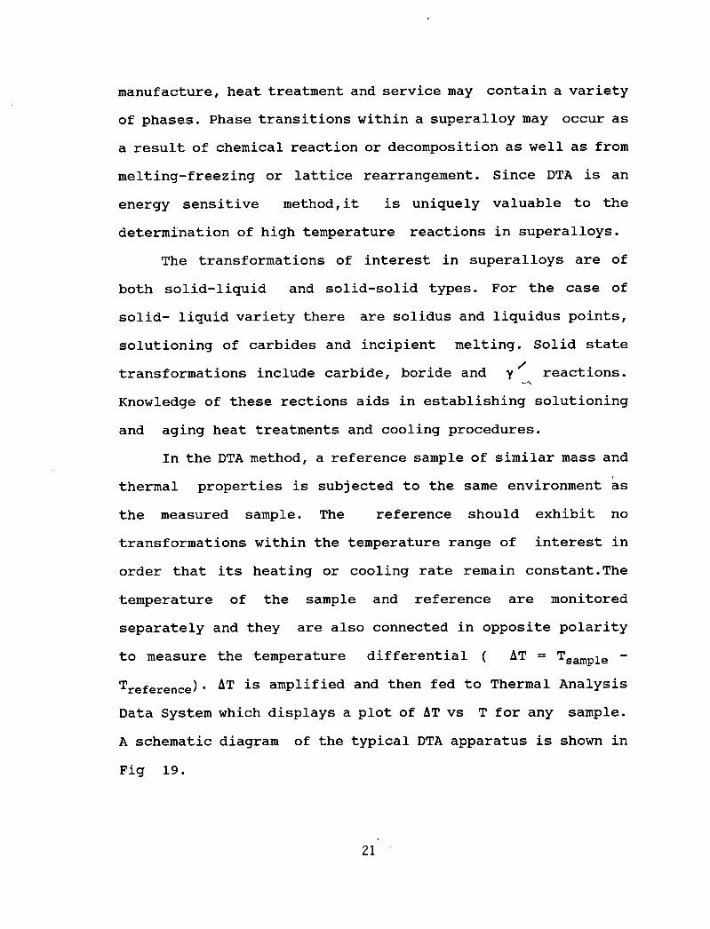
manufacture, heat treatment and service may contain a variety
of phases. Phase transitions within a superalloy may occur as
a result of chemical reaction or decomposition as well as from
melting-freezing or lattice rearrangement. Since DTA is an
energy sensitive method,it is uniquely valuable to the
determination of high temperature reactions in superalloys.
The transformations of interest in superalloys are of
both solid-liquid and solid-solid types. For the case of
solid- liquid variety there are solidus and liquidus points,
solutioning of carbides and incipient melting. Solid state
transformations include carbide, boride and reactions.
Knowledge of these rections aids in establishing solutioning
and aging heat treatments and cooling procedures.
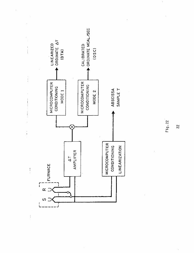
In the DTA method, a reference sample of similar mass and
thermal properties is subjected to the same environment as
the measured sample. The reference should exhibit no
transformations within the temperature range of interest in
order that its heating or cooling rate remain constant.The
temperature of the sample and reference are monitored
separately and they are also connected in opposite polarity
to measure the temperature differential ( AT = Tspie -
Trefere flce)• AT is amplified and then fed to Thermal Analysis
Data System which displays a plot of AT vs T for any sample.
A schematic diagram of the typical DTA apparatus is shown in
Fig 19.
21
U
U-a a - -Jo
0 U
-J
0
coZO
00
a: Ui0
0_Z QLLJ
o op- a:0
a 00.. cn:
ui (D z
U o_z
0..O u F- 2
Ui
-J
Ui
Q Z.) 0 oo 00
U 0
z CC
IL
c"Jc"J C"
•1
Li
It consists of sample holder assembly (incorporating
sample and reference containers mounted in a suitable holder,
thermocouple etc), furnace, temperature programmer, atmosphere
control, cooling control and thermal analysis data station.
As planned, Perkin-Elmer differential thermal analyzer
DTA 1700 was procured and installed alongwith thermal
analysis data system which was possible only after a trade-in
of a component of the existing DSC-4 system purchased under
a separate grant. This increased the versatility and
usefulness of the equipment.
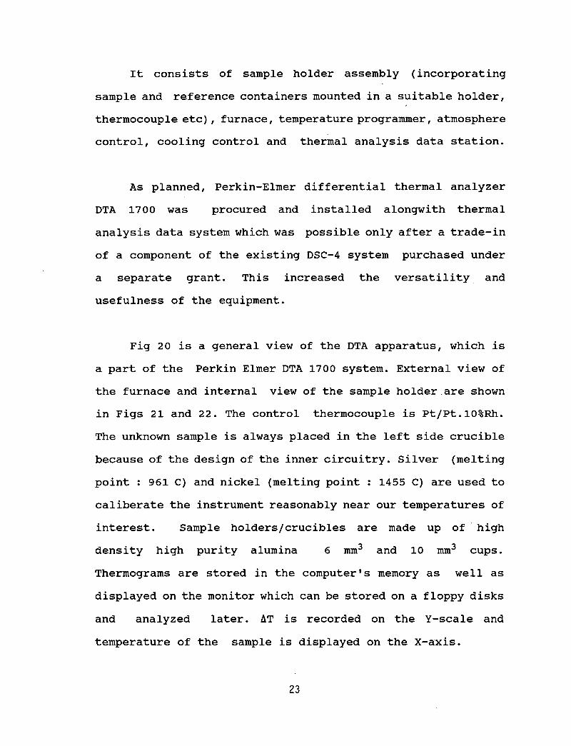
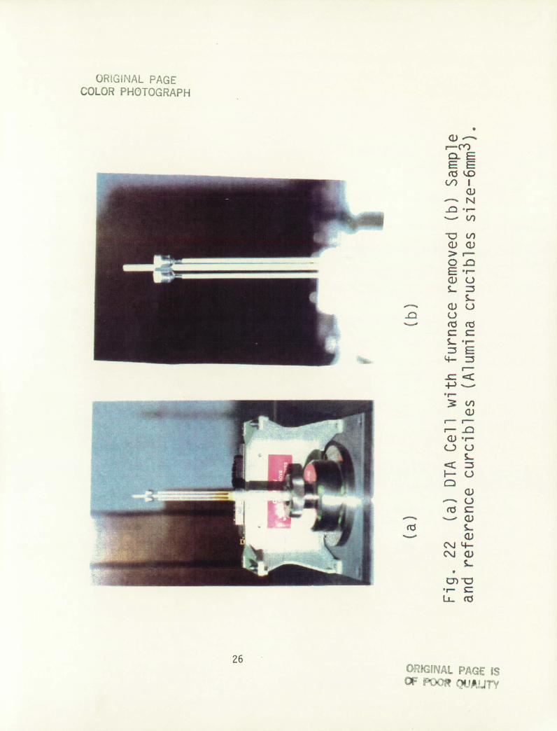
Fig 20 is a general view of the DTA apparatus, which is
a part of the Perkin Elmer DTA 1700 system. External view of
the furnace and internal view of the sample holder are shown
in Figs 21 and 22. The control thermocouple is Pt/Pt.10%Rh.
The unknown sample is always placed in the left side crucible
because of the design of the inner circuitry. Silver (melting
point : 961 C) and nickel (melting point : 1455 C) are used to
caliberate the instrument reasonably near our temperatures of
interest. Sample holders/ crucibles are made up of high
density high purity alumina 6 mm 3 and 10 mm3 cups.
Thermograms are stored in the computer's memory as well as
displayed on the monitor which can be stored on a floppy disks
and analyzed later. AT is recorded on the Y-scale and
temperature of the sample is displayed on the X-axis.
23

ORIGINAL PAGE
COLOR PHOTOGRAPH
I' U
S
, I
I
•1
I
a
N
4
CD CD
'I
Q) a)
ui r(Pi
(1)
LN
:I)
L cL)r-
C\JL
.4-
I—I •r-• LL
H
H-
All
24 ORIGINAL PAGE IS
QVALjy
ORIGINAL PAGE
CCL- - - -.1.
FIG. 21 External View of the Differential Thermal Analyzer
25
Furnace of System DTA 1700
ORIGINAL PAGE IS OF POOR QUAUTY
0
rc1) CL F-EE (dLO
C
26
>1
0
Lr
':1)
(-)0 L
F—U
w
(d
L C)
C'.JC) L
ORLGIN1AL PAGE COLOR PHOTOGRAPH
ocrL PA GE Is
OF POOR rw'JTy
DTA results readily complement those from other methods.
For example, y solvus is traditionally determined
metal lographically by microscopic examination of quenched
samples. Also, carbide reaction is studied by digesting
quenched samples and identifying the carbide phase in the
extracted residue by means of X-ray diffraction methods.
Differential thermal analysis is not meant as a
substitute for metallography or extraction methods but it
does offer some distinct advantages. The mass of the sample
is smaller than required for a mounted, polished and etched
specimen.The time required for DTA is much shorter than other
techniques. DTA yields data which is generated by the entire
bulk of the sample and is unprejudiced by surface preparation.
One major disadvantage is caused by the small DTA sample
size. There is a possibility of unrepresentative data from a
single sample due to inicrosegragation in the material. This,
however, can be turned into an advantage in determining
homogeneity of the material.
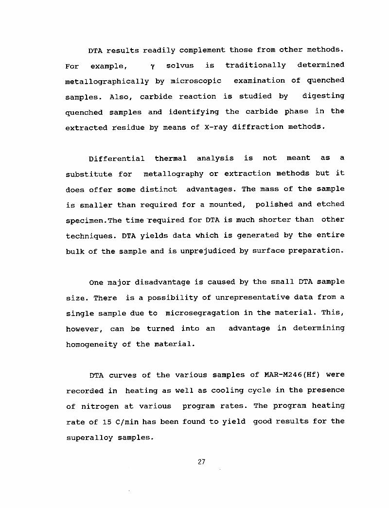
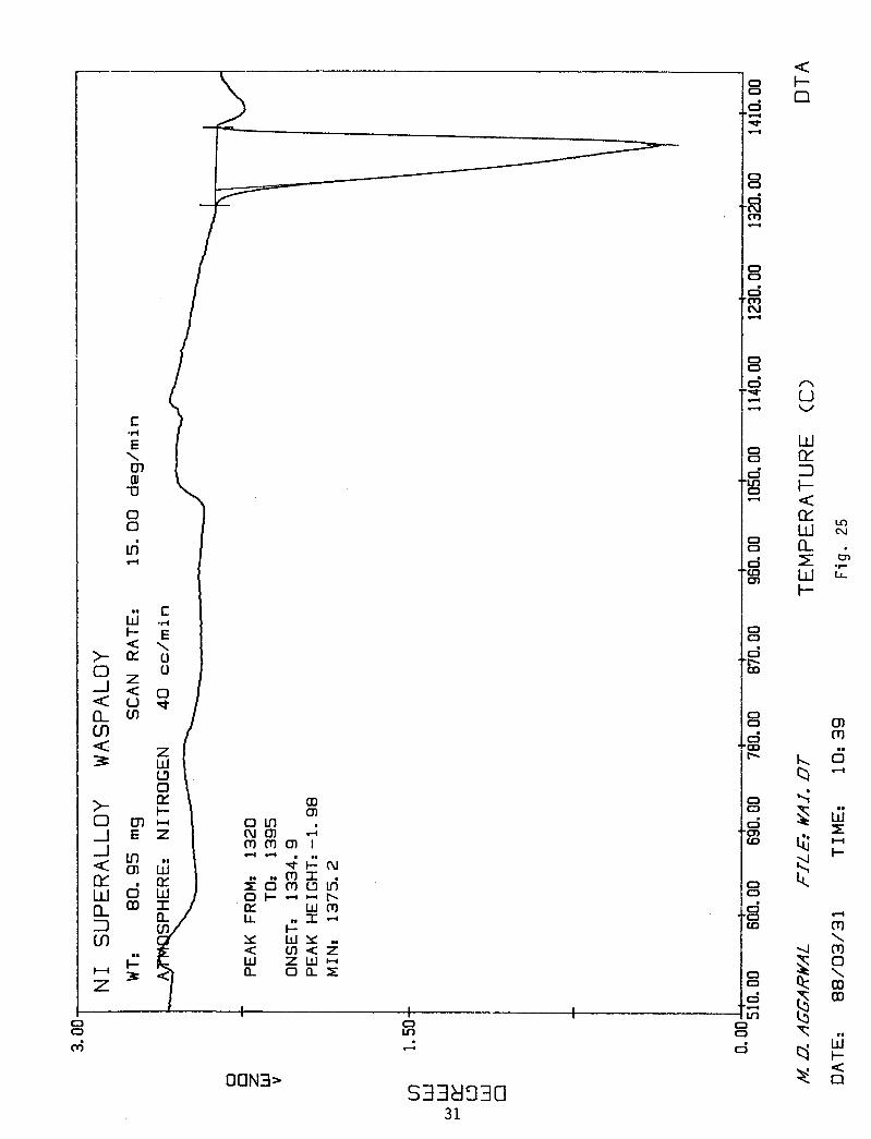
DTA curves of the various samples of MAR-M246(Hf) were
recorded in heating as well as cooling cycle in the presence
of nitrogen at various program rates. The program heating
rate of 15 C/min has been found to yield good results for the
superalloy samples.
27

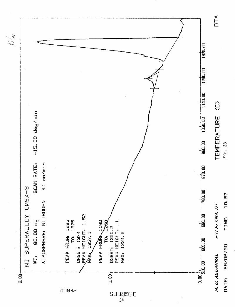
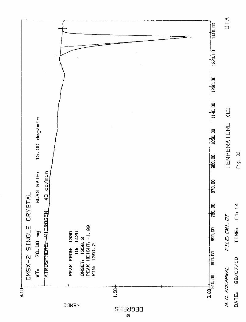
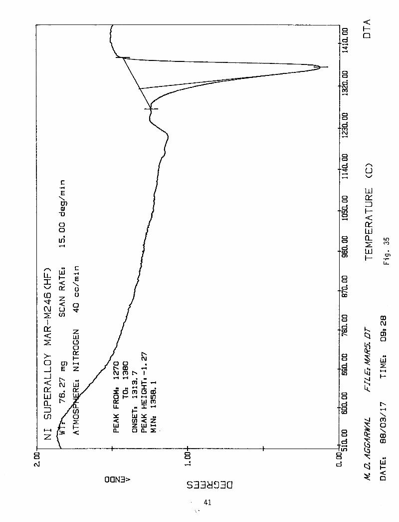
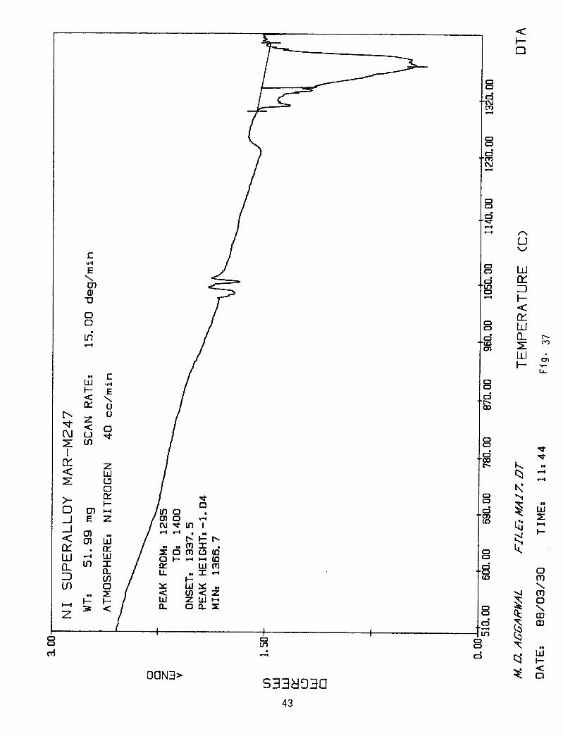
The differential thermal analysis measurement have also
been done on the Ni-based superalloy samples, MAR-M247,
Udimet UD-41, Waspaloy, CMSX-2 and CNSX-3 in polycrystalline
and single crystal form. These curves are shown in Figs 23
to 38. These superalloys have a nominal percent composition
as given in Appendix A. Solidus and liquidus temperatures for
all the above alloys have been evaluated from these curves. An
approximate method of calculating the solidification range
has also been found and the values are found to be in good
agreement. The method is outlined in the next section.
28

4 -
CD CD
C5
CT,
D
C) N-
d CT,
E N 0) a, CD
-o a, 0
-
cm
In N-
•1
W p4 F- E <N CD a:: o
z0 d
<0co
Ln
zCD
o d 1:' 0
>- I- N o 0 co _J E
—'
ç)I d(Y)
,a.—I , •.
<mw (T)I— Cfl m
c.0)1.
Wa)W o-'W
(L LL d W CM
U) 0 IL! < cn<
HF- ILl ZW (L 0 I
co In
LS D
ni — d
00N3>sa3e:Jo:o
29
F-0
I—'
U
w
IL
F-
uJ
uJ--
gL
I4
;

d
-I
C) c\J
cm
C)
d
clot
E N w GI
-D d In
a -1 D a bi CM
0)
e. W •ri HE <N a:
C.) d
z co <0
T-4U)
cm
d 0 w co
a >- a:
o mI-
0 0•
_J E Z OW N d C,
• to co NI- N.
i •a:to
5;;t- jJO)Lti OF—-4U)
U) F U) a
< (n<x F- <
I-.-4 < fl QQ..X
z
I0
U) 0
d
00N3>soa
30
U-,
c -I
CD
d c\J CI) v-I
C) CI) C%J -I
C)
Cv-I
E N C)
C) cr7 a'
C) L1 -D C)
0 0
C) ui C) s-I d
co 0)
F— EC)
<N >-o d o 0
C—
z -J 0
CL U-) C)
U)C)
C)
C-
0 >-o oi otn . d
_J E ('JO) - cm mmCT)
Lf) <O)L
ft 0CT)L C)
Lii OW
IL WO') d EL Li.. ..I-
CD () I—
(f) W.. < (J)<Z W ZWb-4 IL 0 C C)
C)
d
I I
C) LI) C)
s-I d
00N3>
S33JOEO
31
Im
C3
C5
CD
+C5 c\J 0,
cm
0, —a
F N cri w
-DLf)
o —a
0
ul —.4
co cn
Ld HE <N
>-CK o d Dz ° —4i:0
CL (f) (j)
z d Ld N.
0
>- N m c
oU7
00 • .J E Q.-4 —1 d (T)N
in 0)
of
La• •• LflE-
CD
cr- • •• • C)) I • wow (30 X CL m w (L •.Ii d c_n a x w x • Cc)
of < U)<
LU Z <
CL 0
__-- -t I —
U)
CT; .- d
00N3>
S33eD3O
32

00N3> S33èO3O 33
cvi -4 d
H a
U
LiJ
cr-
H
w 0
N-CJ
W
m N
O)
S.
a CT) N
a
co
S.
ILl
co
d c'J —I
C3
CsJ
d —1
£
E N cn It)
-o -
0 oCD
CD -4 CD 0)
LLJ cm I— E <N cr- N
Go u
z <0 mut Cl)
x
U) z Ld U 13 0
>-
o O)-' IflLn
• 0 _J E Z — 0) •0 N
l .4 • -I
1_4N
_-4
CO
< O w • . al —CD • x •• •.NI • • tflI
W 0 w 0N13st 0--i-iU) OI— -iN D
CLbJCT) w w d LL I'-i IL •.I'4 Cl) 1-- I— CD
U) 0 w x x w.. •. x < U)< < CJ)<><
F- F- LU ZW LU ZW<. CL 0CL x CL EL X
dCZ1 cm
cv d
oaN3>S3O3O
34
I-0
eN U
LU CE
F—
ft LiJcO CL C\j
II
N LI)
'S
S.
Qzco co
'I SW
•

Ld
Q co c'J CT)
C) (T)
-I
d
-I C
E N 0) CD C3
.0 Lt co el
0 0
Lli C3 CD
'—I
tcy)
I. £ w F- E D <N c d
0 N. z OD
—<cj
F-Cl) c U)
>- z LIJ N. U (-2 0
w 0) U-,
_J 0)-i 00 o E (T)(\f (\J
z
m 11 i 14 0L
.U) .,Lf)I . ow CF--i--iO)
m 4 X I ci -4 CL I IL ,.I-' I in I F- co x a I U) •1 Z t < u)<z
W ZtiJ. -C 0fL
CD -1
In
In
CQ d
OONB>
seo
35

Cl
CO
d —I
C
E N
01Lii
0 0 —I co
I 0
Lt I- E <N d c
OD
z -J<0 F- (n D C) >-
U 0 0
LIJ a) _J D)'- 00 - (3 E Z m . DW '-4 cn Z .-4
co .-I
-'F--•
(I) ....LflI06 . 0N ffl x Q(T)L C3 OW 0E-' N OF- C)
m :1 UJN - 0.. IL • I -' Ii. •.. I -i C)
C) I U) I- CD X0 W.. Wy..
C/)< W<X < W ZW< W ZW<
0Q 0.. 00 C) C) C)
I I I - LnC) C) C) C) C)
d
00N3>S33èDO
36

------/*--__ ID ID Ji
C3 C" m -4
C) C)
C3 CT) C" -I
C) C)
C3 4-4-I
£ 1
E N C)
C) UI -o C) 4-0 0
L C) C)
C) co 0)
Ld
HE C) <N
C3
zN.co
(!)
x C)
U) zd co
7— LLJ N. U U
0
>-o fl— cc _J E '-.' ('\J
G)
0 .. _-I .-I
(OF—
<ow N .. .. LI) I .
omca) C)
LiJ OW QF— - W C)
0W1 w wc')
CL IL ..I-I— CD
C)
U) 0< U) <Z
F-H W Z.W < O 0 CC)
C)
C3
Ln- C) C) C) C) Ln C)
ui d
00N3>sejoo
37

co co d C...' CT) -4
ci •C1) C'.' -4
C) C) ci -4 -4
.4.4
E N 0) C)
-o -4
0 0C)
4-4 ci co a)
EC) C)
<N ck :: c
ci
z
C) >< C)
(1) C)
U0
>- I-. F-In(0 0 m [no
_ J EZ WW .'-. C3C'JC)W CO
<Ow 0 •, '... .-4 . -
W. 0C')t0) 03 X Q-i-iLfl C) CL LLICr)
ci (f)
(1) a 4. X < (J)<X
Ui zW< CL 0 f
C) ci I r.
Cy (
C'.' 1
00N3>
S333O
38
I-.' U
w ft:
H
LU 0
LU H
c) c)
Li
CT; - d
00N3> S33èJO
F-0
-I
K0
w
1-4
I-
0 -4
N
0 N
Ui I-
0
39

d —4
d —4 m —4
C) d (Sd
Co
-4
d Cl, —4 —1
£ .0-I
E CD N CD DJ aJ
0 0
• CD II) CD
- d I •tj, 0)
LLI
— E C)
<NCD
Of U C)
zo -J<0
HU)CD
U) C)
>- d
U ci 0 w CC 00C)
_J D)'- otn CD
CD E ..-i
(0 NCfl(D
U) • ow CJ---1(D C)
CD N NI CL Li. ..I.-I CD U)
x o w•• < (J)<X Q 0Q w zui<
19 col _tD I to, C)
CD CD (Sd
—
00N3>
seoo
40
c
ci '-4
-4
ci
Mci m cJ
-4
C'-4
E N 0) co ci Lfl
0 0
Ii-; C) C) d co0 )
U W a.HE
'<NC) C)
(•02: 0
U)
zC)
W
> N N C)
C) 0
E Q)I-4
Z00
• N) '-4 ci a, (\JC)NI (0
<NW N ,-. ,-4 4 4.
CK to 4.-i• Z0CT)tCID
W
CD C)CZ
LL ..I* Cl)
U) 0< U)<Z Ui ZW'-4 U- 00. x
z C3 ci
I I I -4 11
C) C) C) C) -I ci
OIJN3>S33èJfJO
41

ci 14 C3
OON3soo
F-0
I-' U
w
F-
LU 0
LU
Fro
Li.
t-1
N 1t N
.,J (T)
rzw
U • w
•
42
- d
00N3>saeio:o
F-
U '-I
w
F-
cr-LU 0
r—. c)
LU F-
It
Li;
'-4 H
0 m N CT, 0 N w
L I-
0
43

ca
d
—4
d (..J CT)
CD co
d
C'%j —I
CD
d
C—4 —4
E N a, cm a.' d U,
0—4
0
cm cm
cico0)
LLJ. HE <N
co Ck o d
N 0Tl
qq z
C3
w
>a:: I—o W-i 00 •
..J E 00 '-' 0) _J o,
m CO
< 0) L
—NE—N
a . a O)I • LU 4 Ui 0 Lfl M xWCT)
CL Li..co
(f) 0 I < (n<X
F- F— Ui ZLi.i<
z C3 d I I I —4 Er)
C3 C3 C3 C3 C3 M
C\i d
00N3>S3è1OO
44

2.5 Approximate method of predicting solidification range of
superalloys
For highly diluted solutions, Hayes and Chipman 6 showed that
the change in the melting point AT of the parent metal M after
adding a small amount of component B is given as:
AT= _(1-kob)
NL,BR(TM)2
where kob is the equilibrium distribution coefficient of
component B in the parent metal M, A HM is the heat of melting
(J/mol) and TM is the melting point of the metal M (K), NL,B is the
molar fraction of component B dissolved in the liquid phase of
metal M and R has the usual meaning (8.314 J K 1 mo11).
The equilibrium distribution coefficient kob is defined at
T=constant by the relationship
ko,b = NSB/NLB
where Ns,B is the molar fraction of component B in the solid
solution based on metal M.
For highly diluted solutions, as in the, case of Ni based
superalloys, the liquidus and solidus curves can be replaced by
straight lines and the solidification range of the solution M-B,
45

denoted by 'B = TLB Ts B in metal M can be expressed by the
relationship
'B'= (1-k0,,) AT=
(1_ko,b)2TRNL,B
If the parent metal M is represented by Ni, the above
equation can be written in the form
3 (1-ko ,b) CB
ko ,b MB
where CB is the concentration of component B in weight
percent, MB is the molecular mass of component B, I is in degrees
celcius.
Assuming the mutual independence of the effect of the
components on the change of melting point of parent metal M, we
can determine the equilibrium solidification range I of the
solution
IZIB
if ,B and NL, B are known.
This range has been calculated for the Ni-based superalloys
MAR-M247, Udimet UD-41, Waspaloy, CMSX-2 and CMSX-3 in
polycrystalline and single crystal form and the values compared
46

with the solidification range evaluated from the differential
thermal analysis. The results of calculation for each superalloy
are given in Tables 1 to 6.
47

TABLE 1
Ni-based Superalloy UD-41
Element CB kob Mb Solidifica tion range
C 0.08 0.22 12.01 15.33
Mn 0.10 0.72 54.94 0.16
Si 0.10 0.36 28.08 3.37
Cr 18.70 0.82 51.99 11.83
Ni Bal. 1.0 58.70
Co 10.80 1.03 58.93 0.14
MO 9.80 0.89 95.94 1.16
Ti 3.21 0.73 47.90 5.57
Al 1.59 0.87 26.98 0.95
Zr 0.07 0.09 91.22 6.20
P 0 0.01 30.97 8.95
Cu 0.01 0.82 63.55 0.01
Ta 0.01 0.74 180.95 0.00
Total I 53.58
From DTA Curve
Ts = 1293.8 CDiff. = 52.5 C
TL = 1345.3 C
48

TABLE 2
Ni-based Superalloy Waspaloy
Elements CB ko,b Mb Solidifica tion Range
C 0.027 0.82 12.01 0.074
Mn 0.03 0.72 54.94 0.049
Si 0.05 0.36 28.08 1.686
Cr 19.19 0.82 51.99 12.14
Ni Bal 1.0 58.7
Co 13.1 1.031 58.93 0.172
Fe 0.96 0.94 55.85 0.054
Mo 4.1 0.89 95.94 0.483
W 0.04 1.5 183.85 0.03
Nb 0.04 0.51 92.91 0.168
Ti 3.02 0.73 47.9 5.24
Al 1.31 0.87 26.98 0.785
Zr 0.057 0.086 91.22 5.052
P 0.006 0.006 30.97 26.55
Ta 0.01 0.74 180.95 0.0042
Total I 52.49
From DTA CurveTs = 1334.9 C
Diff. 40.3 C TL = 1375.2 C
49

TABLE 3
Ni-based Superalloy CMSX-2 (Polycrystalline)
Elements CB ko,b Mb Solidifica tion range
Al 5.62 0.87 26.98 3.368
Co 4.6 1.031 58.93 0.061
Cr 7.9 0.82 51.99 4.997
Cu 0.001 0.82 63.55 0.0005
Fe 0.03 0.94 55.85 0.0017
Mo 0.6 0.89 95.94 0.071
Ni 59.729 1.00 58.7 0
Ta 6.0 0.74 180.95 2.52
Ti 1.00 0.73 47.9 1.735
W 7.9 1.5 183.85 5.96
Al+Ti 6.62 0.8 37.44 7.358
Total I 26.073
From DTA Curve
Ts = 1356.3 C
Diff. = 33.4 C
TL = 1389.7 C
50

TABLE 4
Ni-based Superalloy CMSX-3 (Polycrystalline)
Elements CB kob Mb Solidifica tion Range
Al 5.66 0.87 26.98 3.392
Co 4.6 1.031 58.93 0.061
Cr 7.9 0.82 51.99 4.997
Fe 0.026 0.94 55.85 0.0015
Hf 0.1 0.16 178.49
Mo 0.6 0.89 95.94 0.071
Ni 59.729 1.00 58.7 0
Ta 6.1 0.74 180.95 2.563
Ti 1.02 0.73 47.9 1.769
W 8.0 1.5 183.85 6.036
A1+Ti 6.68 0.8 37.44 7.425
Total I 26.315
From DTA Curve
Ts = 1345.8 C
Diff. = 39.8 C
TL = 1385.6 C
51

TABLE 5
Ni-based Superalloy CMSX-2 (Single Crystal)
Elements CB ko,b Mb Solidifica tion Range
Al 5.59 0.87 26.98 3.35
Co 4.7 1.031 58.93 0.0618
Cr 7.9 0.82 51.99 4.997
Fe 0.032 0.94 55.85 0.0018
No 0.6 0.89 95.94 0.071
Ni 59.728 1.00 58.7 0
Ta 6.0 0.74 180.95 2.52
Ti 0.98 0.73 47.9 1.70
W 7.9 1.5 183.85 5.96
A1+Ti 6.57 0.8 37.44 7.303
Total I 25.966
From DTA CurveTs = 1358.3 C
Diff. = 32.9 C TL = 1391.2 C
52

TABLE 6
Ni-based Superalloy CMSX-3 (Single Crystal)
Elements CB kO,b Mb Solidifica tion Range
Al 5.6 0.87 26.98 3.356
Co 4.6 1.031 58.93 0.061
Cr 7.8 0.82 51.99 4.933
Fe 0.026 0.94 55.85 0.0015
Hf 0.1 0.16 178.49
Mo 0.6 0.89 95.94 0.071
Ni 59.794 1.00 58.7 0
Ta 6.0 0.74 180.95 2.52
Ti 0.99 0.73 47.9 1.72
W 7.9 1.5 183.85 5.961
Al+Ti 6.59 0.8 37.44 7.325
Total I 25.947
From DTA Curve
Ts = 1358 CDiff. = 36.2 C
TL = 1394.2 C
53

3. Publications / Presentations & reports relating to this project
1. Solidification range of Ni-based superalloy MAR-M246(Hf) J.Ala Acad. Science 59(1958) 152.
2. "Microstructural characteristics of Ni-based superalloy at high temperatures" presented at NASA/HBCU forum at Atlanta University center during 25-28, 1987
3. Differential thermal Analysis and heat treatment of Ni-based superalloy presented at Alabama University during Oct 11-13,1988.
4. A study of microstructural characteristics and differential thermal analysis of Ni-based superalloy" proceeding of NASA-HBCU space and engineering forum held at Alabama A&M university, Huntsville, Al during March 22-23,1989 pp382-389.
5. Semi-Annual Technical Report AAMU-NAG-001 submitted to NASA/MSFC May, 1987.
6. Second Year Semi-Annual Technical Report AAMU-NAG-002 submitted to NASA/MSFC September,1988.
54
REFERENCES
1. C.T.Sims, N.S.Stoloff and W.C.Hagel Eds. Superalloys (John Wiley, New York, 1987).
2. G.F. Vander Voort Ed. Applied Metallography (Van Nostrand Reinhold, New York, 1986).
3. G.Blann, Metallography 17,89(1985).
4. F.N.Rhines, MicrostructolOgy (Riederer-Verlag, Stuttgart, 1986)
5. W.W. Wendlandt,Thermal Analysis (John Wiley, New York, 1986).
6. A. Hayes and J.Chipman, Trans. AIME 135,85 (1939).
55

APPENDIX A
56
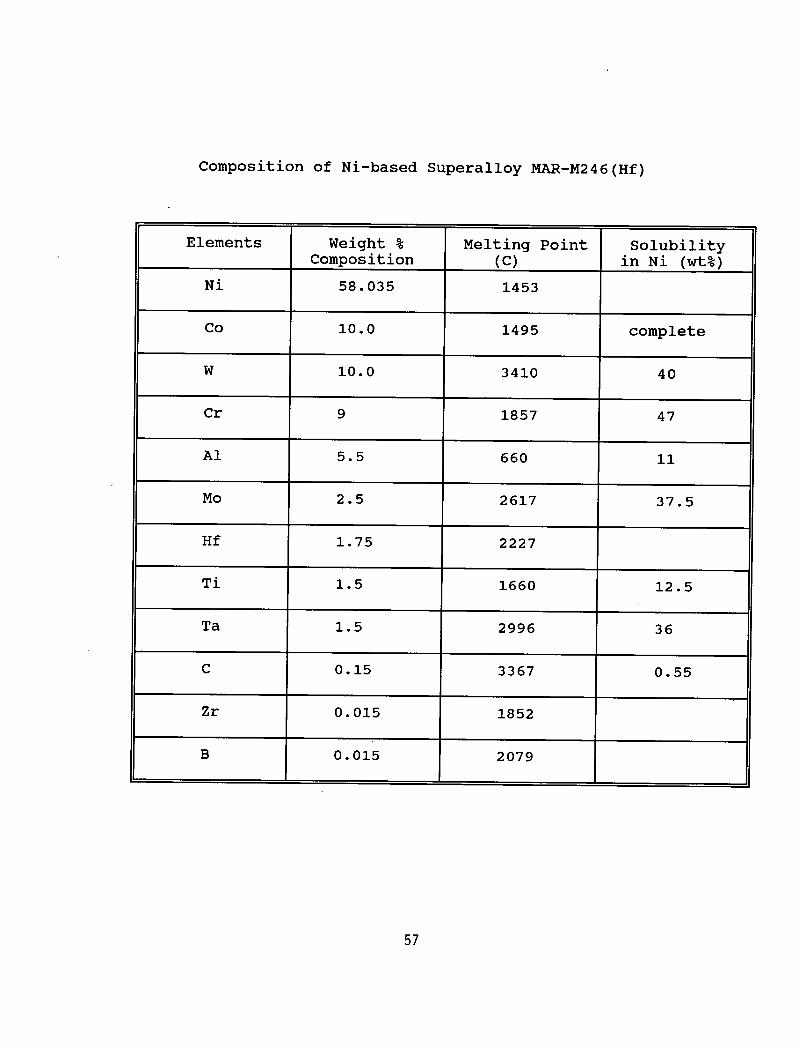
Composition of Ni-based Superalloy MAR-M246(Hf)
Elements Weight % Composition
Melting Point (C)
Solubility in Ni (wt%)
Ni 58.035 1453
Co 10.0 1495 complete
W 10.0 3410 40
Cr 9 1857 47
Al 5.5 660 11
Mo 2.5 2617 37.5
Hf 1.75 2227
Ti 1.5 1660 12.5
Ta 1.5 2996 36
C 0.15 3367 0.55
Zr 0.015 1852
B 0.015 2079
57
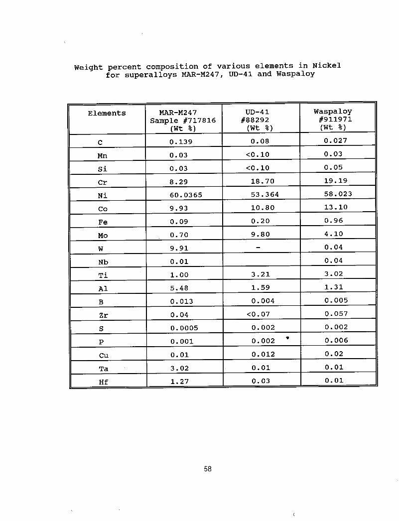
Weight percent composition of various elements in Nickel for superalloys MAR-M247, UD-41 and Waspaloy
Elements MAR-M247 Sample #717816
(Wt %)
UD-41 #88292 (Wt %)
Waspaloy #911971 (Wt %)
C 0.139 0.08 0.027
Mn 0.03 <0.10 0.03
Si 0.03 <0.10 0.05
Cr 8.29 18.70 19.19
Ni 60.0365 53.364 58.023
Co 9.93 10.80 13.10
Fe 0.09 0.20 0.96
Mo 0.70 9.80 4.10
W 9.91 - 0.04
Nb 0.01 0.04
Ti 1.00 3.21 3.02
Al 5.48 1.59 1.31
B 0.013 0.004 0.005
Zr 0.04 <0.07 0.057
S 0.0005 0.002 0.002
P 0.001 0.002 • 0.006
Cu 0.01 0.012 0.02
Ta 3.02 0.01 0.01
Hf 1.27 1 0.03 0.01
58
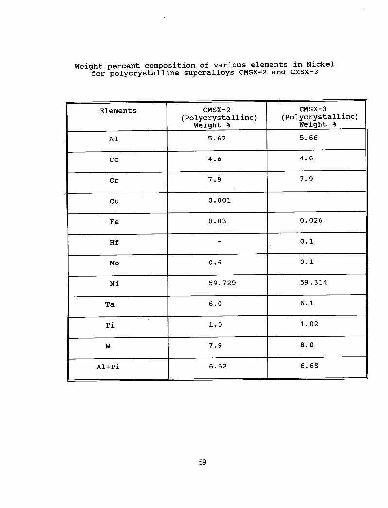
Weight percent composition of various elements in Nickel for polycrystalline superalloys CMSX-2 and CMSX-3
Elements CMSX-2 (Polycrystalline)
Weight %
CMSX-3 (Polycrystalline)
Weight %
Al 5.62 5.66
Co 4.6 4.6
Cr 7.9 7.9
Cu 0.001
Fe 0.03 0.026
Hf - 0.1
Mo 0.6 0.1
Ni 59.729 59.314
Ta 6.0 6.1
Ti 1.0 1.02
W 7.9 8.0
Al+Ti 6.62 6.68
59

Weight percent composition of various elements in Nickel for single crystal superalloy CMSX-2 and CMSX-3
Elements CNSX-2 (Single crystal)
Weight %
CMSX-3 (Single crystal)
Weight %
AL 5.59 5.6
Co 4.7 4.6
Cr 7.9 7.8
Fe 0.032 0.026
Hf - 0.1
Mo 0.6 0.6
Ni 59.728 59.794
Ta 6.0 6.0
Ti 0.98 0.99
W 7.9 7.9
Al+Ti 6.57 6.59 di
60