Mitigation of Power Quality Problems in Grid- Interactive ...
23
Mitigation of Power Quality Problems in Grid- Interactive Distributed Generation System This is the Accepted version of the following publication Bhende, CN, Kalam, Akhtar and Malla, SG (2016) Mitigation of Power Quality Problems in Grid-Interactive Distributed Generation System. International Journal of Emerging Electric Power Systems, 17 (2). 165 - 172. ISSN 2194- 5756 The publisher’s official version can be found at https://www.degruyter.com/view/j/ijeeps.2016.17.issue-2/ijeeps-2015-0163/ijeeps-2015- 0163.xml Note that access to this version may require subscription. Downloaded from VU Research Repository https://vuir.vu.edu.au/34596/
Transcript of Mitigation of Power Quality Problems in Grid- Interactive ...

Mitigation of Power Quality Problems in Grid-Interactive Distributed Generation System
This is the Accepted version of the following publication
Bhende, CN, Kalam, Akhtar and Malla, SG (2016) Mitigation of Power Quality Problems in Grid-Interactive Distributed Generation System. International Journal of Emerging Electric Power Systems, 17 (2). 165 - 172. ISSN 2194-5756
The publisher’s official version can be found at https://www.degruyter.com/view/j/ijeeps.2016.17.issue-2/ijeeps-2015-0163/ijeeps-2015-0163.xmlNote that access to this version may require subscription.
Downloaded from VU Research Repository https://vuir.vu.edu.au/34596/
1
Mitigation of Power Quality Problems in Grid-Interactive Distributed Generation
System C. N. Bhende1, A. Kalam2, S. G. Malla3
1,3Indian Institute of Technology Bhubaneswar, India-751013 2College of Engineering and Science, Victoria University, Melbourne, Australia
Abstract: Having an inter-tie between low/medium voltage grid and distributed
generation (DG), both exposes to power quality (PQ) problems created by each other.
This paper addresses various PQ problems arise due to integration of DG with grid. The
major PQ problems are due to unbalanced and non-linear load connected at DG,
unbalanced voltage variations on transmission line and unbalanced grid voltages which
severely affect the performance of the system. To mitigate the above mentioned PQ
problems, a novel integrated control of distribution static shunt compensator
(DSTATCOM) is presented in this paper. DSTATCOM control helps in reducing the
unbalance factor of PCC voltage. It also eliminates harmonics from line currents and
makes them balanced. Moreover, DSTATCOM supplies the reactive power required by
the load locally and hence, grid need not to supply the reactive power. To show the
efficacy of the proposed controller, several operating conditions are considered and
verified through simulation using MATLAB/SIMULINK.
Keywords: Distributed generation, power quality conditioner, voltage variations, non-
linear and unbalanced load compensation and reactive power compensation.
1Corresponding author - Tel/Fax: +916742306248, E-mail: [email protected]
2
1. INTRODUCTION
The continuously increasing energy demand, along with the necessity of higher
reliability requirements, are driving the modern power systems towards distributed
generation (DG) as an alternative source. Wind turbines, Fuel cells (FC), Photovoltaic
(PV), Batteries, etc. are nowadays the most commonly available DGs for generation of
power mostly in peak times or in rural areas [1]. The hybrid system (i.e., combination of
DGs) offers the strengths of each type of sources that complement one another and
provides more reliability and also cost effective [2-3]. Usually, DGs are connected near
the local load and are connected to the grid through a short/medium transmission line
for the low/medium voltage network. To deliver high quality and reliable power, DGs
should appear as a controllable unit that responds to changes in the system [4]. DG
should preferably tie to the utility grid so that any surplus energy generated within them
can be channelled to the grid. Similarly, any shortfall can be replenished from the grid.
However, due to inter-tie connection between DG and grid, they are exposed to each
other’s inner disturbances such as: harmonics, voltage unbalance, voltage variations and
other power quality (PQ) problems [5]. These PQ problems can be arose from three
sides
• Loads connected at DG end
• Transmission line connected between grid and DG
• Grid side
Local loads connected at DG end are usually unbalanced and non-linear in nature
which results in injection of harmonic and negative sequence currents into the grid [6].
The presence of harmonic current increases the losses in ac power lines, transformers

3
and rotating machines. The load imbalance causes oscillatory torque leading to
mechanical stress and malfunctions of sensitive equipment.
Another major issue associated with DG connection is the voltage variation on
transmission line connected between grid and DG. The voltage variations mainly result
from impedance of transmission lines, loading types and uneven distribution of single-
phase loads. The scenarios become much severe in the low-voltage microgrid system
due to reverse power flow contributed by distributed generations in either three or single
phase connection [7]. Voltage fluctuations cause system losses, capacity reduction,
transformer overloading and motor overheating. Moreover, voltage variation results in
output limitation of DGs, nuisance tripping of protected devices and malfunction of
sensitive equipment. According to IEEE Std. 1547.2-2008 [8], voltage fluctuations are
limited to ±5% as renewable energy sources are paralleled to low-voltage systems. The
voltage unbalance factor (VUF) below 2.0%–3.0% is acceptable for both manufactures
and utility, where %VUF is defined as the ratio of the negative-sequence voltage to the
positive sequence voltage [9]. Further, in practice, usually upto 5% unbalance occurs in
grid voltages and due to this VUF at PCC voltage increases further. Therefore, voltage
regulation is absolutely needed to allow more DGs to join for grid connected operation.
In such a system, distribution static shunt compensator (DSTATCOM) and active power
filter (APF) are suitable for power quality improvement of the distribution system [5,
10, 11]. Hence, to mitigate the above mentioned PQ problems a PQ conditioner is
recommended at DG side [5, 10-13].
In [10], authors used DSTATCOM to mitigate the voltage fluctuations at
microgrid-bus (i.e., PCC) due to unbalanced load and reactive power demand. However,
the above approach did not consider the unbalance in grid voltages since in practice grid

4
voltages may vary upto 5%. In [12-13], authors considered that each DG is connected to
two converters, one in series and other in parallel. By controlling those two inverters,
authors claimed the enhancement of both quality of power within microgrid and quality
of current flowing between microgrid and utility system. However, such systems may
not be cost effective and control will be complex in case of multiple DGs. Moreover,
the important control configuration i.e., control of DC-link voltage of micro-source is
missing in the above mentioned literature. In [14], authors considered a new
configuration in which DG is connected to DC-link of unified power quality conditioner
(UPQC). The reported system in [14] can compensate voltage sag and swell, voltage
interruption, harmonics and reactive power in both interconnected mode and islanding
mode. However, in [14], authors did not consider unbalance in grid voltage which is a
common phenomenon in distribution networks. Moreover, configuration proposed in
[14] may be critical since DG is connected to DC-bus of UPQC and UPQC being a
power electronic device is susceptible for faults. Hence, DG owners may have
limitations to accept such configuration due to various technical limitations.
Recently in [11], a new control algorithm of PQ conditioner for DG system is
proposed to mitigate the effect of unbalanced and non-linear load connected at DG. In
this paper, we further extended the work presented in [11] for the regulation of PCC
voltage due to unbalanced grid voltages and unbalanced loads connected at transmission
line between grid and DG. Hence, in this paper, many usually occurring PQ problems
due to interconnection of DG and grid are considered and integrated control is proposed
for the mitigation of those PQ problems.
The main inverter associated with DG (i.e., which connects DG to PCC) works for
active power transfer from DG to PCC. The purpose of DG inverter control is to

5
coordinate active power sharing with grid which depends on DG’s available power and
load demand. The PQ problem of non-linear and unbalanced load (connected at DG-
side) can be mitigated by DG inverter [15]. However, it is not wise to burden the DG
inverter since it is the main interface between DG source and remaining power network.
Therefore, in this paper, DSTATCOM is connected at PCC (refer Fig. 1) for the
mitigation of PQ problems. Across the transmission line, assume that unbalanced loads
are connected at different load buses as shown in Fig. 1. Due to this, unbalanced
currents flow the in transmission line which causes unbalance voltages at PCC. This
unbalance increases further when grid voltages are unbalanced. The proposed
DSTATCOM control helps in reducing VUF at PCC voltage. Moreover, DSTATCOM
control is developed in such a fashion that it should provide reactive power demand of
DG-side load locally and hence, neither inverter nor grid should supply the reactive
power.
Non-Linear and Unbalanced Loads
ilabc
ist,abc
LDST CDST
DSTATCOM
VDST
DC side of DG
DGiDGbc
DG Inverter
Lf
Vdc
C
iabc
Grid
RG+jXG R1+jX1
Load bus-1
Load bus-2
R2+jX2
Load bus-3
R3+jX3
PCCR=0.25Ω /kmX=0.8Ω /km
Fig. 1: Schematic of DG connected to utility grid through medium transmission line

6
2. CONTROL OF DG INVERTER AND DSTATCOM
The control schemes for DG inverter and DSTATCOM are mentioned as follows:
2.1) DG Inverter Control
The main aim of DG inverter control is to coordinate active power sharing with
grid which depends on available power of DG and load demand. Once power balance
among DG, load and grid is achieved, the dc-link voltage of inverter ( dcV ) is
maintained at its reference value which in turn helps in maintaining ac voltage of
inverter [16].
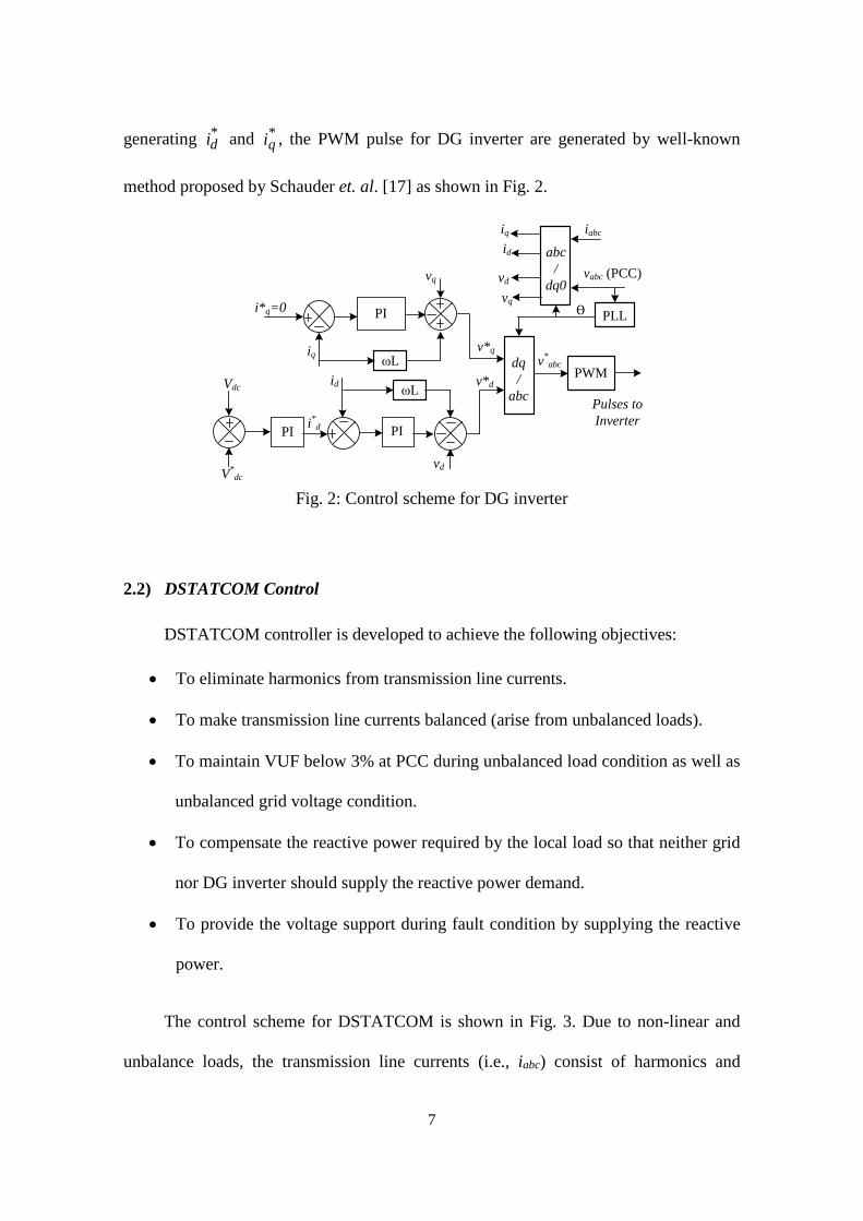
The control scheme for inverter is presented in Fig. 2. The proposed control
strategy for inverter is realized in synchronous rotating frame [17]. The synchronous
rotating frame angle (Ө) is generated through phase locked loop (PLL) by sensing PCC
voltages as shown in Fig. 2. Using Ө, inverter output currents and PCC voltages are
decomposed into d-axis and q-axis components. The d-axis component corresponds to
the real power and q-axis component relates to the reactive power. The output power of
renewable sources always fluctuates because of weather condition, for example solar
irradiance in case of photovoltaics depends on weather condition. Due to this, there is
always power mismatch between generation and load. Mismatch of real power changes
the dc side voltage ( dcV ) of DG. Therefore, error between dcV and reference dc-link
voltage ( *dcV ) is fed to the proportional plus integral (PI) controller to obtain *
di which
corresponds to the reference component of real power which DG supplies to PCC.
Since, DG inverter is not designed for reactive power supply, *qi is made zero. After
7
generating *di and *
qi , the PWM pulse for DG inverter are generated by well-known
method proposed by Schauder et. al. [17] as shown in Fig. 2.
vabc (PCC)
iabc
PLL
id
vd
iq
vqi*q=0
iq
V*dc
Vdc
i*d
id ωL
vd
ωL
vq
dq/
abc
Ѳ
v*abc
PWM
Pulses to Inverter
abc/
dq0
PI
PI PI
v*q
v*d
Fig. 2: Control scheme for DG inverter
2.2) DSTATCOM Control
DSTATCOM controller is developed to achieve the following objectives:
• To eliminate harmonics from transmission line currents.
• To make transmission line currents balanced (arise from unbalanced loads).
• To maintain VUF below 3% at PCC during unbalanced load condition as well as
unbalanced grid voltage condition.
• To compensate the reactive power required by the local load so that neither grid
nor DG inverter should supply the reactive power demand.
• To provide the voltage support during fault condition by supplying the reactive
power.
The control scheme for DSTATCOM is shown in Fig. 3. Due to non-linear and
unbalance loads, the transmission line currents (i.e., iabc) consist of harmonics and
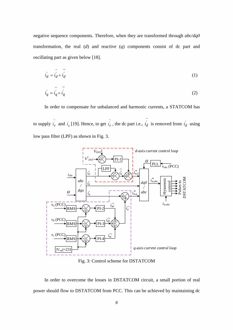
8
negative sequence components. Therefore, when they are transformed through abc/dq0
transformation, the real (d) and reactive (q) components consist of dc part and
oscillating part as given below [18].
~'''ddd iii +=
−
(1)
~'''qqq iii +=
−
(2)
In order to compensate for unbalanced and harmonic currents, a STATCOM has
to supply ~'di and '
qi [19]. Hence, to get ~'di , the dc part i.e.,
−'di is removed from '
di using
low pass filter (LPF) as shown in Fig. 3.
va (PCC)RMS
vb (PCC)RMS
vc (PCC)RMS
VDST
dq0/
abc
V*DST
ist,abc
Hys
tere
sis
cont
rol
Puls
es to
D
STA
TC
OM
PLLѲ
vabc (PCC)LPF
abc/
dqo
iabc
Ѳ
d-axis current control loop
q-axis current control loop
PI-1
PI-2
PI-3
PI-4
|Vref|=231
id‘
i0‘
iq‘
iqa‘‘
iqb‘‘
iqc‘‘
iq‘‘
id‘~
ist,d*
ist,q*
ist,abc*
Fig. 3: Control scheme for DSTATCOM
In order to overcome the losses in DSTATCOM circuit, a small portion of real
power should flow to DSTATCOM from PCC. This can be achieved by maintaining dc

9
voltage of DSTSTCOM ( DSTV ) at its reference value. Hence, DSTV is compared with
reference dc voltage and error is fed to PI-1 controller. The output of PI-1 controller is
then added with ~'di and thus reference d-axis current component of DSTATCOM ( *
,dsti )
is generated as shown in Fig. 3.
Let us now consider the q-axis current control loop. DSTATCOM compensates
both harmonic and reactive power required by the DG-side load. Hence, reactive power
component of current i.e., 'qi is used in the DSTATCOM control. Due to unbalanced
load and unbalanced grid voltages, the PCC voltage becomes unbalanced. Therefore,
one of the objectives of DSTATCOM control is to maintain balanced voltages at PCC.
As change in voltage reflects the change in reactive power, the PCC voltages are taken
into the q-axis control loop. In order to compensate for unbalanced voltages, individual
phase voltages are sensed and compared with reference voltage and corresponding
errors are fed to the three PI controllers (PI-2, PI-3, PI-4) as shown in Fig. 3. The
outputs of those three PI controllers are added together to get reactive power component
( "qi ) related to the voltage change. The current components '
qi and "qi are then added to
generate reference q-axis current component of DSTATCOM ( *,qsti ). After generating
*,dsti and *
,qsti , the reference currents of DSTATCOM ( *,abcsti ) are generated from
dq0/abc transformation. The gate pulses are generated through hysteresis controller by
comparing actual DSTATCOM currents ( abcsti , ) and *,abcsti as shown in Fig. 3.

10
3. RESULTS AND DISCUSSIONS
The parameters of the system and their ratings are given in Table-1. The rating of DG
inverter and DSTATCOM are determined based on 500 kW DG and load power.
Details are mentioned in the Appendix. Moreover, design of DSTATCOM capacitance
(CDST) and inductance (LDST) is also mentioned in the Appendix.
Table-1: System Parameters
Sr. No. Components Rating
1 Nominal voltage at PCC (i.e.,
output voltage of DG inverter)
400 V
(ph-ph)
2 *dcV 666 V
3 Transformer 400V / 25kV
4 Length of transmission line 50 km
5 Grid 25 kV (ph-ph), XG/RG =10
6 *DSTV 660 V
7 CDST 1100 μF
8 LDST 7.5 mH
The performance of inverter and DSTATCOM control techniques is tested by
considering the following cases:
Case-1: Condition of unbalanced grid voltages and load
To show the efficacy of the proposed controller, the simulation is carried out by
considering the unbalanced loads. Next, the grid voltages are maintained at balanced
state upto 1.02 sec. and after that they are made unbalanced as shown in Fig. 4. Due to
unbalanced grid voltages, the PCC voltages become more unbalanced after 1.02 sec. as
shown in Fig. 5 and VUF is found to be 8.97%. This unbalance nature of voltages can

11
be compensated with proposed DSTATCOM control and PCC voltages with
DSTATCOM operation are shown in Fig. 6. From Fig. 6, it can be observed that PCC
voltages become balanced (after 1.02 sec.) with DSTATCOM control and the VUF
factor of PCC voltage becomes 1.04%. Hence, DSTATCOM helps in keeping VUF
within limit irrespective of unbalanced grid voltages and unbalanced loads.
Time (s)
Vol
tage
(kV
)
1 1.01 1.02 1.03 1.04 1.05 1.06-25-20-15-10-505
10152025 va vb vc
Fig. 4: Instantaneous grid voltages {Case-1}
Time (s)
Vol
tage
(v)
1 1.01 1.02 1.03 1.04 1.05 1.06-400-300
-200
-100
0
100
200
300
400va vb vc
Fig. 5: Instantaneous voltages at PCC without DSTATCOM {Case-1}
Time (s)
Vol
tage
(V)
1 1.01 1.02 1.03 1.04 1.05 1.06-400-300
-200
-100
0
100
200
300
400 va vb vc
Fig. 6: Instantaneous voltages at PCC with DSTATCOM {Case-1}

12
Case-2: Active power sharing between grid and DG
Consider the photovoltaic (PV) system as a distribution generation (DG) source
connected to utility grid through transmission line as shown in Fig. 1. Considering that
load demand is 28 kW and PV system is producing 16.9 kW, the remaining load power
requirement is fulfilled by the grid as shown in Fig. 7. Now assume that solar irradiance
is reduced from 900 W/m2 to 800 W/m2 at t= 0.5 sec. (Fig. 7). As solar irradiance
reduces, the PV power reduces and hence, grid supplies more power to meet the load
demand as shown in Fig. 7. As PV power reduces, the dc-link voltage of inverter also
reduces momentarily. However, due to control action of DG inverter (Fig. 2), the dc
voltage stabilizes at its reference value as shown in Fig. 8.
Time (s)
Pow
er (k
W)
5
10
15
20
25
30
0.4 0.5 0.6 0.7 0.8 0.9
Load power
PV power
Grid power
Fig. 7: Active power sharing between grid and DG system {Case-2}
Time (s)
V dc (
V)
600610620630640650660670680690700
0.4 0.5 0.6 0.7 0.8 0.9
Fig. 8: Dc-link voltage of inverter {Case-2}
13
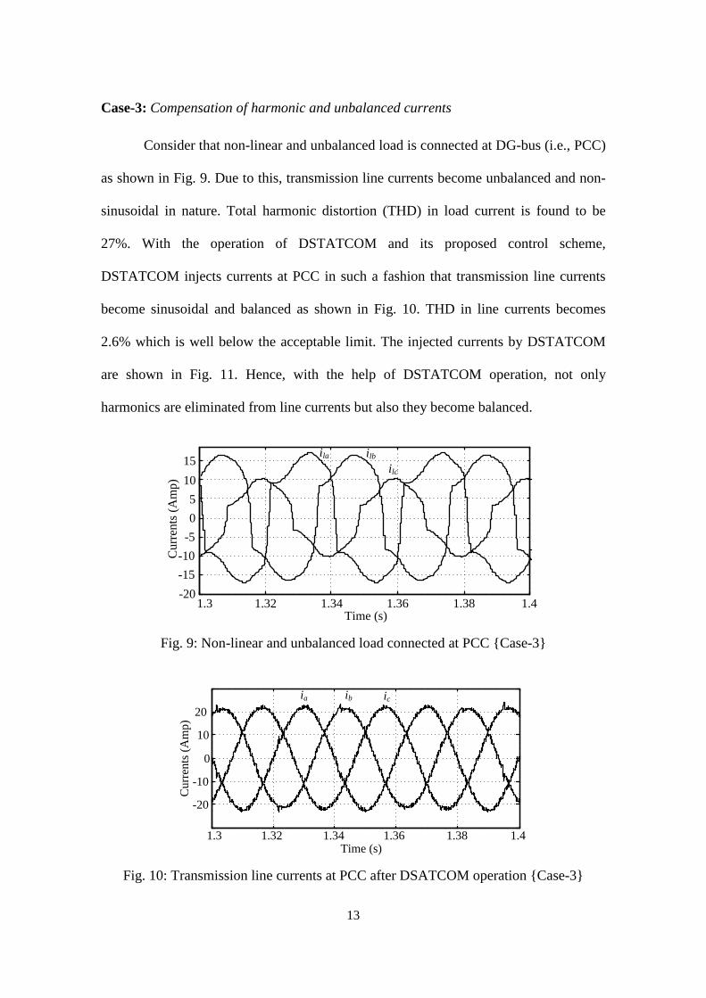
Case-3: Compensation of harmonic and unbalanced currents
Consider that non-linear and unbalanced load is connected at DG-bus (i.e., PCC)
as shown in Fig. 9. Due to this, transmission line currents become unbalanced and non-
sinusoidal in nature. Total harmonic distortion (THD) in load current is found to be
27%. With the operation of DSTATCOM and its proposed control scheme,
DSTATCOM injects currents at PCC in such a fashion that transmission line currents
become sinusoidal and balanced as shown in Fig. 10. THD in line currents becomes
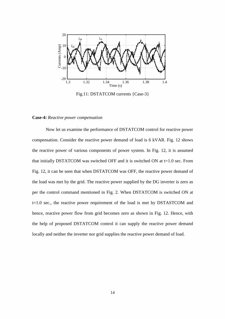
2.6% which is well below the acceptable limit. The injected currents by DSTATCOM
are shown in Fig. 11. Hence, with the help of DSTATCOM operation, not only
harmonics are eliminated from line currents but also they become balanced.
Cur
rent
s (A
mp)
-20-15-10
-505
1015
1.3 1.32 1.34 1.36 1.38 1.4
ila ilb
ilc
Time (s) Fig. 9: Non-linear and unbalanced load connected at PCC {Case-3}
Cur
rent
s (A
mp)
1.3 1.32 1.34 1.36 1.38 1.4
-20
-10
0
10
20ia
Time (s)
ib ic
Fig. 10: Transmission line currents at PCC after DSATCOM operation {Case-3}
14
-20
-10
0
10
20
1.3 1.32 1.34 1.36 1.38 1.4
idb idc
ida
Cur
rent
s (A
mp)
Time (s) Fig.11: DSTATCOM currents {Case-3}
Case-4: Reactive power compensation
Now let us examine the performance of DSTATCOM control for reactive power
compensation. Consider the reactive power demand of load is 6 kVAR. Fig. 12 shows
the reactive power of various components of power system. In Fig. 12, it is assumed
that initially DSTATCOM was switched OFF and it is switched ON at t=1.0 sec. From
Fig. 12, it can be seen that when DSTATCOM was OFF, the reactive power demand of
the load was met by the grid. The reactive power supplied by the DG inverter is zero as
per the control command mentioned in Fig. 2. When DSTATCOM is switched ON at
t=1.0 sec., the reactive power requirement of the load is met by DSTASTCOM and
hence, reactive power flow from grid becomes zero as shown in Fig. 12. Hence, with
the help of proposed DSTATCOM control it can supply the reactive power demand
locally and neither the inverter nor grid supplies the reactive power demand of load.

15
-10
1
2
3
4
5
6
7
Time (s)
Reac
tive p
ower
(kV
AR)
DSTATCOM powerPower from Grid
Inverter power
0.9 0.95 1 1.05 1.1 1.15 1.2 1.25
DSTATCOM is switched ON Fig. 12: Reactive power compensation by DSTATCOM {Case-4}
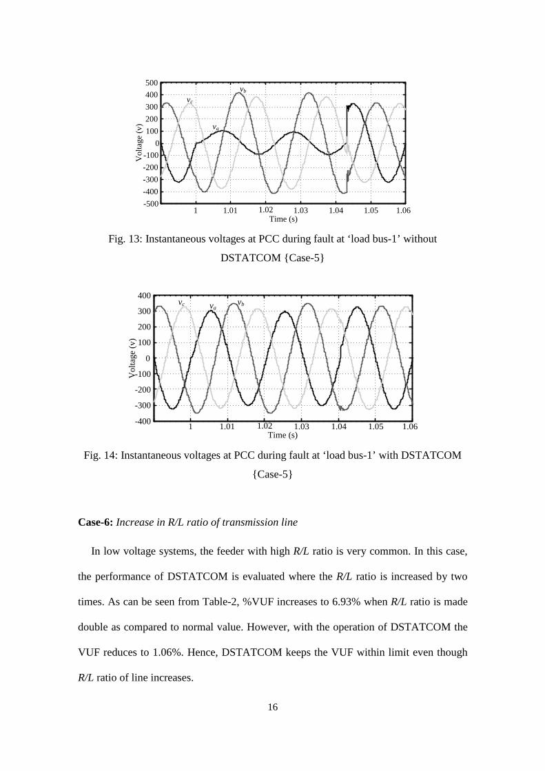
Case-5: Condition of fault at ‘Load bus-1’
Consider that phase-A to ground (LG) fault occurred at ‘Load bus 1’ at t=1.0 sec.
(Fig. 13). Assume that CB is taking time of two cycles to open the faulty feeder after
occurrence of fault. During this period, voltage of faulty phase (i.e., phase-A) reduces to
large extent (Fig. 13) since large current flows through faulty feeder. Sensitive load
connected to PCC may get affected by dip in PCC voltages. After incorporating
DSTATCOM control, it supplies the reactive power so that PCC voltages are
maintained near to rated value as shown in Fig. 14. Hence, DSTATCOM plays an
important role under this condition. With DSTATCOM, dip in faulty phase voltage
reduces to about 6.8%. Similarly rise in healthy phase also reduces. Hence,
DSTATCOM provides voltage support during fault and quality of voltage is improved
at PCC during fault.
16
Time (s)
Vol
tage
(v)
-500-400-300-200-100
0100200300400500
1 1.01 1.02 1.03 1.04 1.05 1.06
va
vb
vc
Fig. 13: Instantaneous voltages at PCC during fault at ‘load bus-1’ without
DSTATCOM {Case-5}
1 1.01 1.02 1.03 1.04 1.05 1.06Time (s)
Vol
tage
(v)
-400
-300
-200
-100
0
100
200
300
400va
vbvc
Fig. 14: Instantaneous voltages at PCC during fault at ‘load bus-1’ with DSTATCOM
{Case-5}
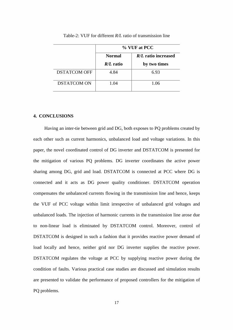
Case-6: Increase in R/L ratio of transmission line
In low voltage systems, the feeder with high R/L ratio is very common. In this case,
the performance of DSTATCOM is evaluated where the R/L ratio is increased by two
times. As can be seen from Table-2, %VUF increases to 6.93% when R/L ratio is made
double as compared to normal value. However, with the operation of DSTATCOM the
VUF reduces to 1.06%. Hence, DSTATCOM keeps the VUF within limit even though
R/L ratio of line increases.
17
Table-2: VUF for different R/L ratio of transmission line
% VUF at PCC
Normal
R/L ratio
R/L ratio increased
by two times
DSTATCOM OFF 4.84 6.93
DSTATCOM ON 1.04 1.06
4. CONCLUSIONS
Having an inter-tie between grid and DG, both exposes to PQ problems created by
each other such as current harmonics, unbalanced load and voltage variations. In this
paper, the novel coordinated control of DG inverter and DSTATCOM is presented for
the mitigation of various PQ problems. DG inverter coordinates the active power
sharing among DG, grid and load. DSTATCOM is connected at PCC where DG is
connected and it acts as DG power quality conditioner. DSTATCOM operation
compensates the unbalanced currents flowing in the transmission line and hence, keeps
the VUF of PCC voltage within limit irrespective of unbalanced grid voltages and
unbalanced loads. The injection of harmonic currents in the transmission line arose due
to non-linear load is eliminated by DSTATCOM control. Moreover, control of
DSTATCOM is designed in such a fashion that it provides reactive power demand of
load locally and hence, neither grid nor DG inverter supplies the reactive power.
DSTATCOM regulates the voltage at PCC by supplying reactive power during the
condition of faults. Various practical case studies are discussed and simulation results
are presented to validate the performance of proposed controllers for the mitigation of
PQ problems.

18
5. APPENDIX
A. Ratings of Inverter
For 500 kW DG is considered, hence inverter is designed only based on DG active
power (i.e., reactive power supplied by DG = 0). Inverter consists of six IGBT devices.
The current rating of device is calculated is approximately 750 A.
B. Ratings of DSTATCOM
For 500 kW load, considering that power factor needs to be maintained at 0.9, the
VAR rating of DSTATCOM will be 242.2kVAR. Required reactive power during
voltage sag (for no. of cycles = 6 and % dip = 40) is calculated as 22.6kVAR [20].
Hence, total rating of DSTATCOM is considered as 297.49kVAR (242.2 + 55.29).
C. Design of dsL,Cds of DSTATCOM
Dc side capacitor and interfacing inductance of DSTATCOM are given by [21]
( )( ) ( )22 4.18.1
22
mmds
VV
nTXXC−
−= (3)
sw
mds fh
VL
46.1
= (4)
where
mV (peak value of the source voltage) = 2231 ,
X (rating of the DSTATCOM) = 297.49 kVA,
n (no. of cycles considered for voltage sag) = 9,
T ( time period of the each cycle) =20 msec.,
h (constant) =16, and

19
swf (switching frequency) = 1050 Hz.
From (1) and (2), the values of dsC and dsL are calculated and given as, dsC =1100 μF,
dsL = 7.5 mH.
ACKNOWLEDGEMENT
This work was supported by INSA, Govt. of India under “Indo-Australia Science and
Technology Visiting Fellowship Programme - 2013”.
REFERENCES
[1] D. Menniti, C. Picardi, A. Pinnarelli and D. Sgro, “Power management by grid
connected inverters using a voltage and current control strategy for microgrid
applications”, in Proc. of International Symp. on Power Electronics, Electrical
Drives, Automation and Motion (SPEEDAM), pp. 1414-1419, 2008.
[2] C. Wang and M.H. Nehrir, “Power Management of a Stand- Alone
Wind/Photovoltaic/Fuel Cell Energy System”, IEEE Transactions on Energy
Conversion, Vol. 23, No. 3, pp. 957 - 967, Sept. 2008.
[3] F. Katiraei, M. Iravani, “Power management strategies for a microgrid with
multiple distributed generation units”, IEEE Trans. on Power Systems, Vol. 21,
No.4, pp. 1821-1831, Nov. 2006.
[4] T. Kaipia, P. Peltoniemi, J. Lassila, P. Salonen and J. Partanen, “Power
electronics in smart grids-impact on power system reliability”, in Proc. of CIRED
Int. Conf., Germany, June 2008.
[5] J. M. Guerrero, P. C. Loh, T. L. Lee and M. Chandorkar, “Advanced Control
Architectures for Intelligent Microgrids—Part II: Power Quality, Energy Storage,
20
and AC/DC Microgrids”, IEEE Transactions on Industrial Electronics, Vol. 60,
No. 4, pp. 1263 – 1270, April 2013.
[6] IEEE Application Guide for IEEE Std. 1547™, IEEE Standard for
Interconnecting Distributed Resources with Electric Power Systems, 2011.
[7] C. L. Masters, “Voltage rise: The big issue when connecting embedded generation
to long 11 kV overhead lines,” Inst. Elect. Eng. Power Eng. J., Vol. 16, No. 1, pp.
5–12, Feb. 2002.
[8] IEEE Standard for Interconnecting Distributed Resources With Electric Power
Systems, IEEE Std. 1547.2-2008, 2008.
[9] A. V. Jouanne and B. Banerjee, “Assessment of voltage unbalance,” IEEE Trans.
Power Del., Vol. 16, No. 4, pp. 782–790, Oct. 2001.
[10] Tzung-Lin Lee, Shang-Hung Hu and Yu-Hung Chan,“ D-STATCOM With
Positive-Sequence Admittance and Negative-Sequence Conductance to Mitigate
Voltage Fluctuations in High-Level Penetration of Distributed-Generation
Systems”, IEEE Transactions on Industrial Electronics, Vol. 60, No. 4, pp. 1417-
1428, April 2013.
[11] C. N. Bhende and A. Kalam, “Power Quality Conditioner for Microgrid”,
Australasian Universities Power Engineering Conference (AUPEC), Hobart,
TAS, Australia, 29 Sept.-3 Oct. 2013.
[12] Y. W. Li, D. M. Vilathgamuwa and P. C. Loh, “Microgrid Power Quality
Enhancement Using a Three-Phase Four-Wire Grid-Interfacing Compensator”,
IEEE Transactions on Industry Applications, Vol. 41, No. 6, pp. 1707-1719,
Nov/Dec. 2005.

21
[13] Y. W. Li, D. M. Vilathgamuwa and P. C. Loh, “A Grid-Interfacing Power Quality
Compensator for Three-Phase Three-Wire Microgrid Applications”, IEEE
Transactions on power electronics, Vol. 21, No. 4, pp. 1021-1031, July 2006.
[14] B. Han, B. Bae, H. Kim and S. Baek, “Combined Operation of Unified Power-
Quality Conditioner with Distributed Generation”, IEEE Transactions on Power
Delivery, Vol. 21, No. 1, pp. 330-338, Jan. 2006.
[15] X. Tang, K. M. Tsang, and W. L. Chan, “A Power Quality Compensator with DG
Interface Capability Using Repetitive Control”, IEEE Transactions on Energy
Conversion, Vol. 27, No.2, pp. 213 - 219, June 2012.
[16] C. N. Bhende, S. Mishra and Siva Ganesh Malla, “Permanent Magnet
Synchronous Generator-Based Standalone Wind Energy Supply System”, IEEE
Transactions on Sustainable Energy, Vol. 2, No. 4, pp. 361-373, Oct. 2011.
[17] C. Schauder and H. Mehta, “Vector analysis and control of advanced static VAR
Compensators”, IEE Proceedings-C, Vol. 140, No. 4, pp. 299-306, July 1993.
[18] C. Salim and B. M. Toufik, “Intelligent Controllers for Shunt Active Filter to
Compensate Current Harmonics Based on SRF and SCR Control Strategies”,
International Journal on Electrical Engineering and Informatics, Vol. 3, No. 3,
2011.
[19] M. Aredes, J. Hafner and K. Heumann, “Three-Phase Four-Wire Shunt Active
Filter Control Strategies”, IEEE Transactions on Power Electronics, Vol. 12, No.
2, pp. 311-318 , March 1977.
[20] S. B. Karanki, N. Geddada, M. K. Mishra and B. Kalyan Kumar, “A
DSTATCOM Topology with Reduced DC-Link Voltage Rating for Load

22
Compensation with Nonstiff Source”, IEEE Transactions on Power Electronics,
Vol. 27, No. 3, pp. 1201-1211, March 2012.
[21] Hendri Masdi et al, “Design of a Prototype D-Statcom for Voltage Sag
Mitigation”, National Power & Energy Conference (PECon) Procedings, Kuala
Lumpur, Malaysia, pp. 61-66, 2004.