
Mirror Technologies for Giant Telescopes · Jim Burge Professor College of Optical Sciences and ......
76
Mirror Technologies for Giant Telescopes Jim Burge Professor College of Optical Sciences and Steward Observatory [email protected]
Transcript of Mirror Technologies for Giant Telescopes · Jim Burge Professor College of Optical Sciences and ......
Mirror Technologies
for
Giant Telescopes
Jim BurgeProfessor
College of Optical Sciences and
Steward Observatory
J. H. Burge University of Arizona 2
Today’s talk
• Introduce giant astronomical telescopes
planning to be built in the next decade
• Summarize challenges of making the mirrors for
these telescopes
• Present technologies and capabilities at
University of Arizona that enable manufacture of
the mirrors
J. H. Burge University of Arizona 3
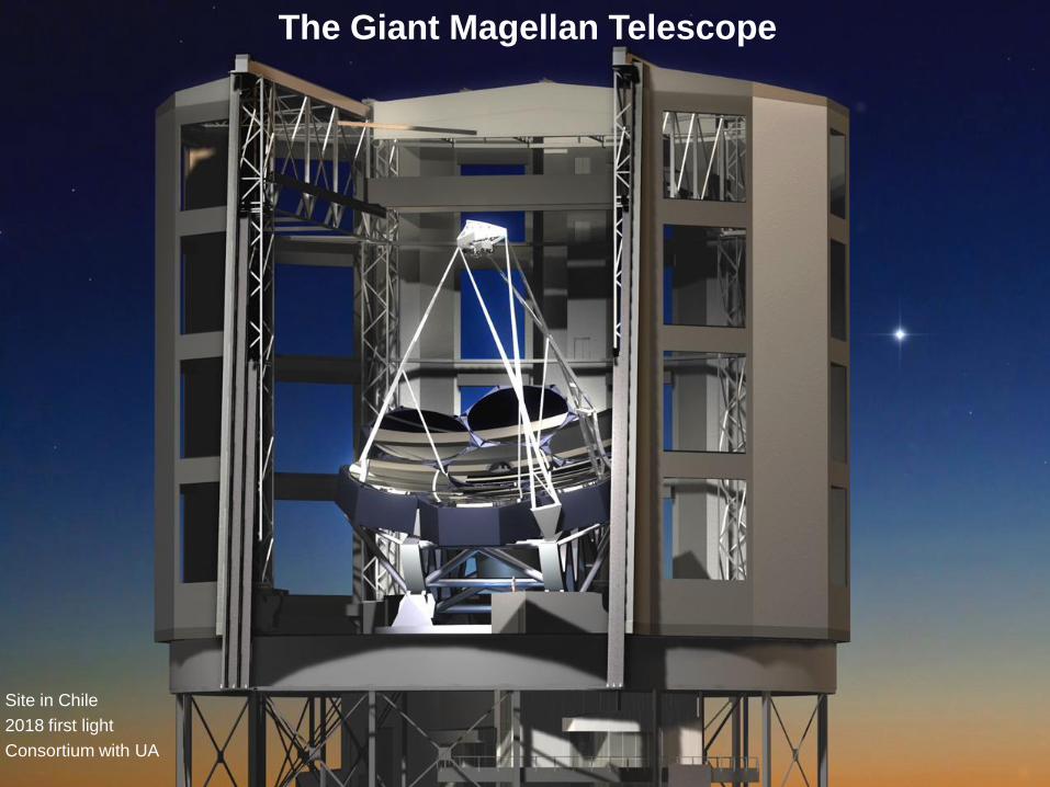
The Giant Magellan Telescope
Site in Chile
2018 first light
Consortium with UA
J. H. Burge University of Arizona 4
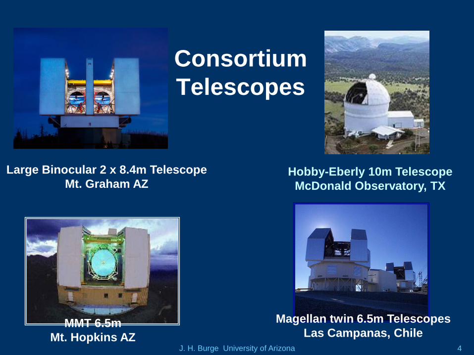
Consortium
Telescopes
Large Binocular 2 x 8.4m Telescope
Mt. Graham AZHobby-Eberly 10m Telescope
McDonald Observatory, TX
MMT 6.5m
Mt. Hopkins AZ
Magellan twin 6.5m Telescopes
Las Campanas, Chile
J. H. Burge University of Arizona 5
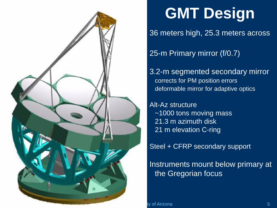
GMT Design36 meters high, 25.3 meters across
25-m Primary mirror (f/0.7)
3.2-m segmented secondary mirrorcorrects for PM position errors
deformable mirror for adaptive optics
Alt-Az structure
~1000 tons moving mass
21.3 m azimuth disk
21 m elevation C-ring
Steel + CFRP secondary support
Instruments mount below primary at
the Gregorian focus
J. H. Burge University of Arizona 6
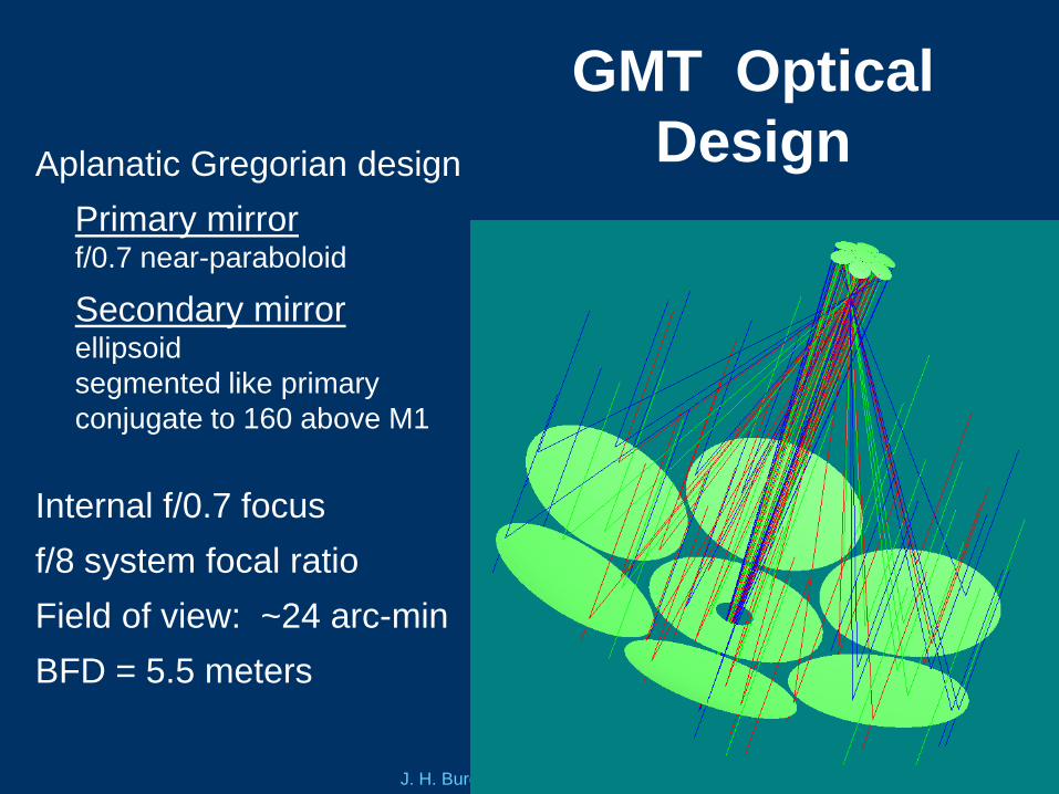
GMT Optical
DesignAplanatic Gregorian design
Primary mirrorf/0.7 near-paraboloid
Secondary mirrorellipsoid
segmented like primary
conjugate to 160 above M1
Internal f/0.7 focus
f/8 system focal ratio
Field of view: ~24 arc-min
BFD = 5.5 meters
J. H. Burge University of Arizona 7
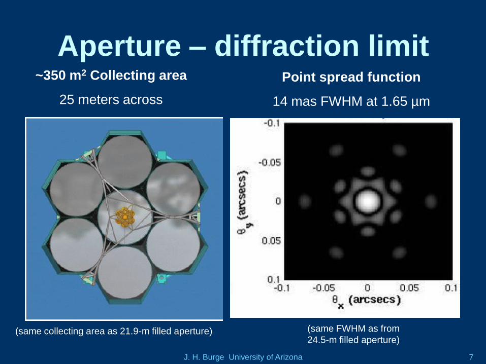
Aperture – diffraction limit~350 m2 Collecting area
25 meters across
Point spread function
14 mas FWHM at 1.65 µm
(same FWHM as from
24.5-m filled aperture)(same collecting area as 21.9-m filled aperture)
J. H. Burge University of Arizona 8
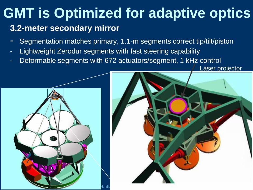
GMT is Optimized for adaptive optics3.2-meter secondary mirror
- Segmentation matches primary, 1.1-m segments correct tip/tilt/piston
- Lightweight Zerodur segments with fast steering capability
- Deformable segments with 672 actuators/segment, 1 kHz controlLaser projector
J. H. Burge University of Arizona 9
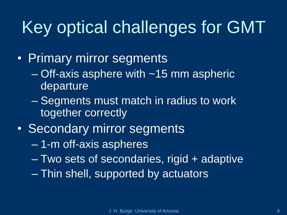
Key optical challenges for GMT
• Primary mirror segments
– Off-axis asphere with ~15 mm aspheric departure
– Segments must match in radius to work together correctly
• Secondary mirror segments
– 1-m off-axis aspheres
– Two sets of secondaries, rigid + adaptive
– Thin shell, supported by actuators
J. H. Burge University of Arizona 10
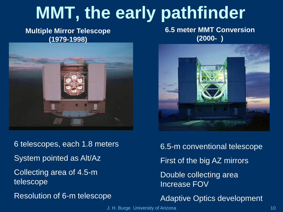
MMT, the early pathfinderMultiple Mirror Telescope
(1979-1998)
6.5 meter MMT Conversion
(2000- )
6 telescopes, each 1.8 meters
System pointed as Alt/Az
Collecting area of 4.5-m
telescope
Resolution of 6-m telescope
6.5-m conventional telescope
First of the big AZ mirrors
Double collecting area
Increase FOV
Adaptive Optics development
J. H. Burge University of Arizona 11
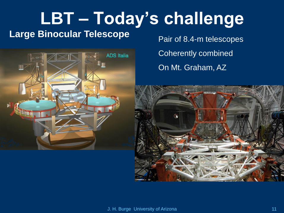
LBT – Today’s challengeLarge Binocular Telescope
Pair of 8.4-m telescopes
Coherently combined
On Mt. Graham, AZ
J. H. Burge University of Arizona 12
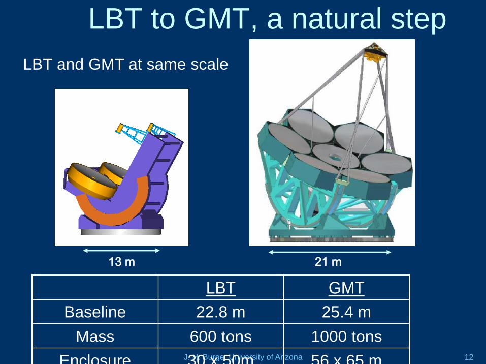
13 m 21 m
LBT to GMT, a natural step
LBT GMT
Baseline 22.8 m 25.4 m
Mass 600 tons 1000 tons
Enclosure 30 x 50m 56 x 65 m
LBT and GMT at same scale

J. H. Burge University of Arizona 13
Primary mirror manufacturing
Cast lightweight mirror blanks
High stiffness, low weight
Thermal responsive
Low expansion borosilicate glass
Spin cast for near net shape
GMT mirrors follow procedures
already used for 9 large mirrors,
now in optical systems
J. H. Burge University of Arizona 14
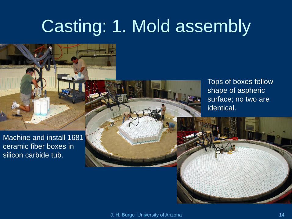
Casting: 1. Mold assembly
Machine and install 1681
ceramic fiber boxes in
silicon carbide tub.
Tops of boxes follow
shape of aspheric
surface; no two are
identical.
J. H. Burge University of Arizona 15
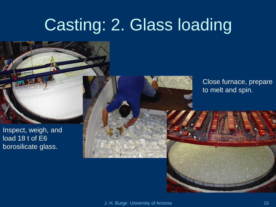
Casting: 2. Glass loading
Close furnace, prepare
to melt and spin.
Inspect, weigh, and
load 18 t of E6
borosilicate glass.
J. H. Burge University of Arizona 16
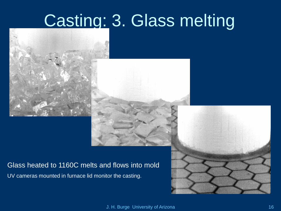
Casting: 3. Glass melting
Glass heated to 1160C melts and flows into mold
UV cameras mounted in furnace lid monitor the casting.
J. H. Burge University of Arizona 17
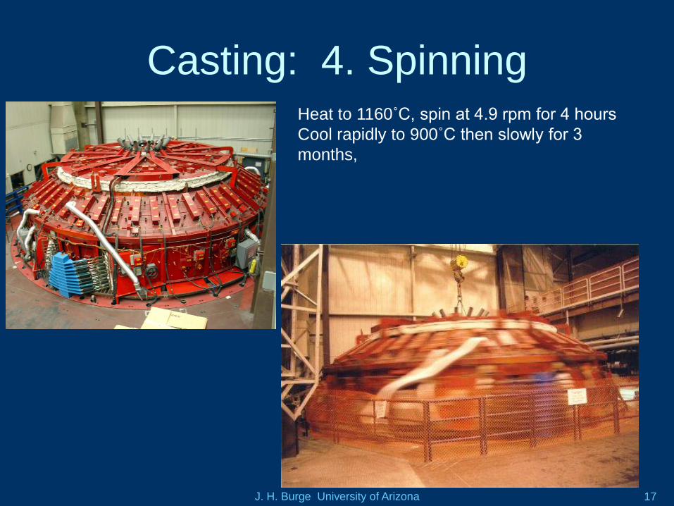
Casting: 4. SpinningHeat to 1160˚C, spin at 4.9 rpm for 4 hours
Cool rapidly to 900˚C then slowly for 3
months,
J. H. Burge University of Arizona 18
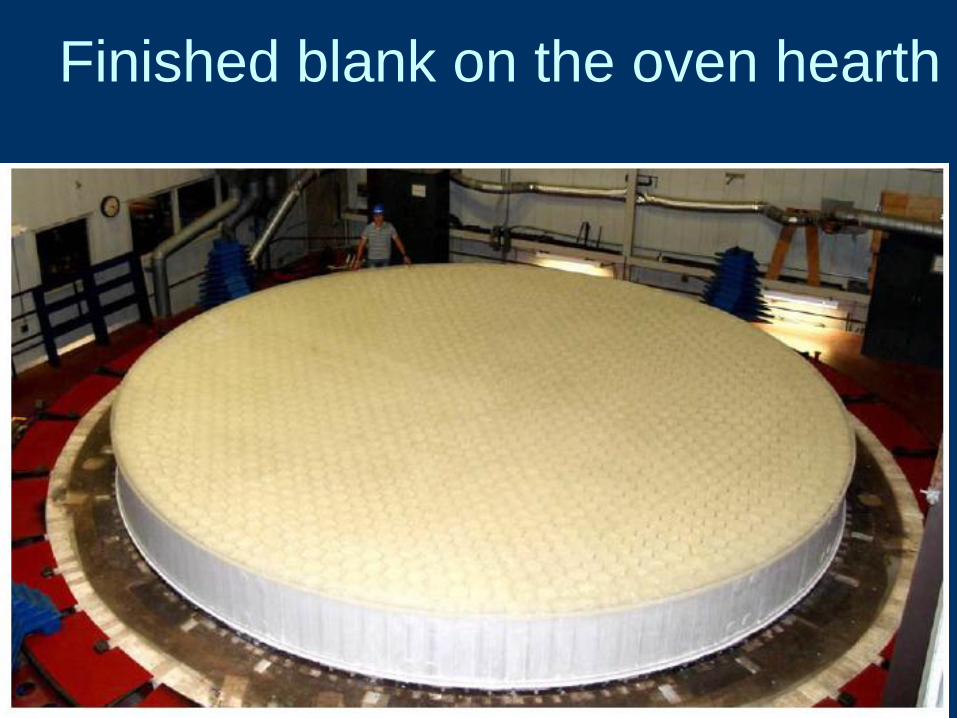
Finished blank on the oven hearth
J. H. Burge University of Arizona 19
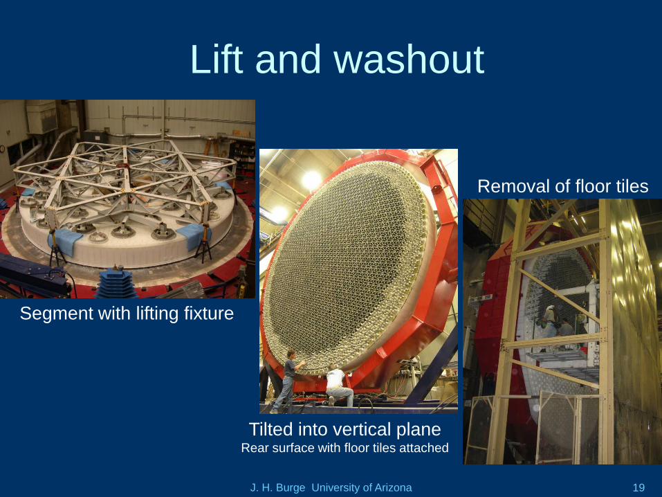
Lift and washout
Tilted into vertical planeRear surface with floor tiles attached
Segment with lifting fixture
Removal of floor tiles
J. H. Burge University of Arizona 20
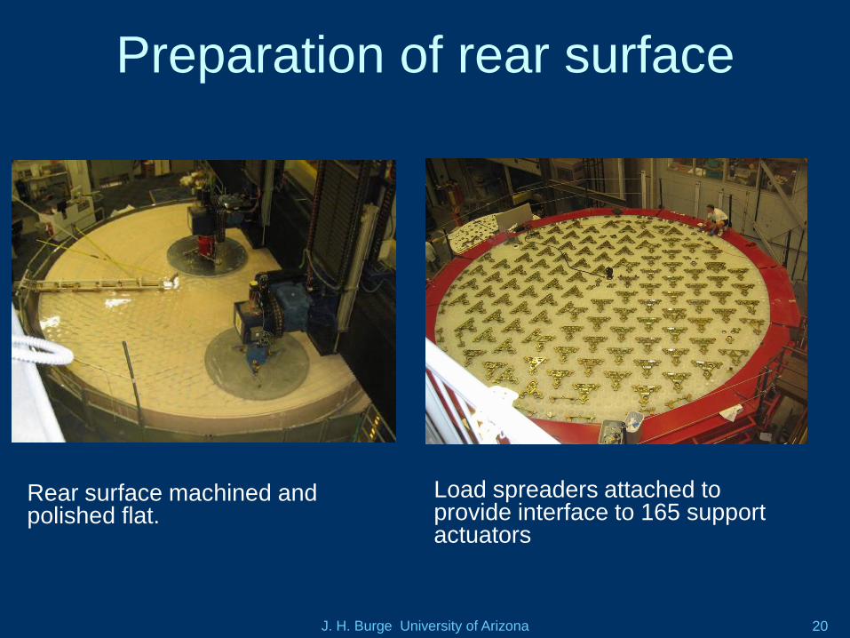
Preparation of rear surface
Rear surface machined and polished flat.
Load spreaders attached to provide interface to 165 support actuators
J. H. Burge University of Arizona 21
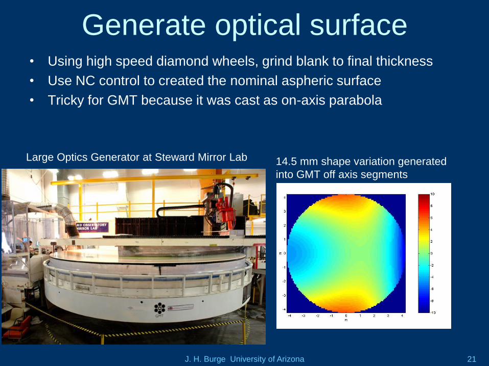
Generate optical surface• Using high speed diamond wheels, grind blank to final thickness
• Use NC control to created the nominal aspheric surface
• Tricky for GMT because it was cast as on-axis parabola
Large Optics Generator at Steward Mirror Lab 14.5 mm shape variation generated
into GMT off axis segments
J. H. Burge University of Arizona 22
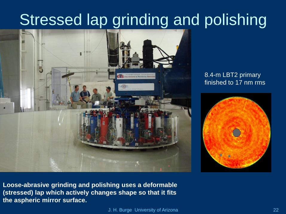
Stressed lap grinding and polishing
Loose-abrasive grinding and polishing uses a deformable
(stressed) lap which actively changes shape so that it fits
the aspheric mirror surface.
8.4-m LBT2 primary
finished to 17 nm rms
J. H. Burge University of Arizona 23
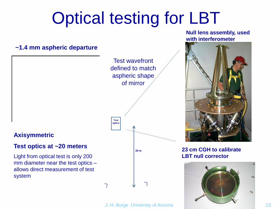
Optical testing for LBT
Axisymmetric
Test optics at ~20 meters
Light from optical test is only 200
mm diameter near the test optics –
allows direct measurement of test
system
Test
optics
~1.4 mm aspheric departure
Test wavefront
defined to match
aspheric shape
of mirror
20 m
Null lens assembly, used
with interferometer
23 cm CGH to calibrate
LBT null corrector
J. H. Burge University of Arizona 24
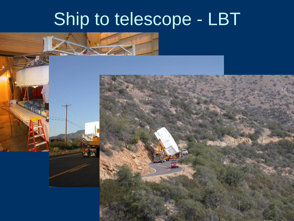
Ship to telescope - LBT
J. H. Burge University of Arizona 25
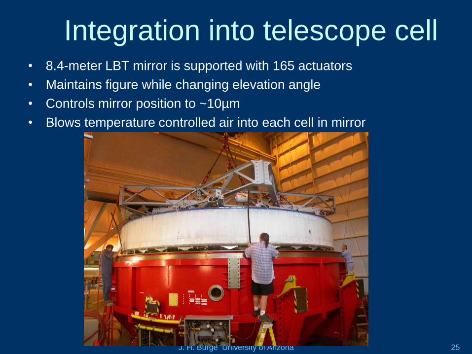
Integration into telescope cell• 8.4-meter LBT mirror is supported with 165 actuators
• Maintains figure while changing elevation angle
• Controls mirror position to ~10µm
• Blows temperature controlled air into each cell in mirror
J. H. Burge University of Arizona 26
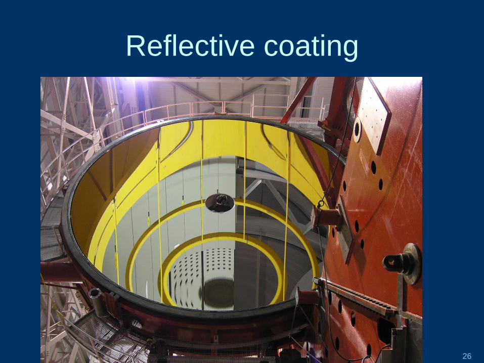
Reflective coating
J. H. Burge University of Arizona 27
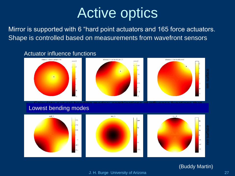
Active opticsMirror is supported with 6 “hard point actuators and 165 force actuators.
Shape is controlled based on measurements from wavefront sensors
• Calculate actuator influence functions: deflection of segment’s optical
surface caused by 1 N force at one actuator.
• Calculate natural bending modes: combinations of influence functions that
have most impact with least force (normalized to 1 N rms force).
nm
surf
ace
nm
surf
ace
Actuator influence functions
Lowest bending modes
(Buddy Martin)
J. H. Burge University of Arizona 28
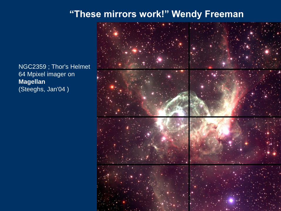
“These mirrors work!” Wendy Freeman
NGC2359 ; Thor's Helmet
64 Mpixel imager on
Magellan
(Steeghs, Jan'04 )
J. H. Burge University of Arizona 29
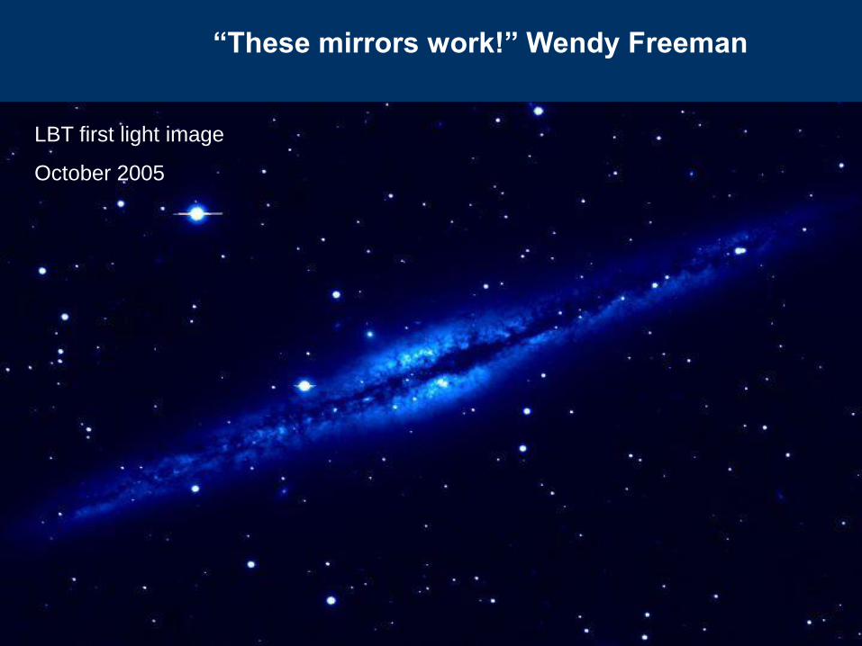
“These mirrors work!” Wendy Freeman
LBT first light image
October 2005
J. H. Burge University of Arizona 30
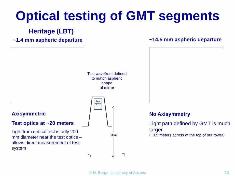
Optical testing of GMT segmentsHeritage (LBT) GMT
Axisymmetric
Test optics at ~20 meters
Light from optical test is only 200
mm diameter near the test optics –
allows direct measurement of test
system
No Axisymmetry
Light path defined by GMT is much
larger(~3.5 meters across at the top of our tower)
Test
optics
~1.4 mm aspheric departure ~14.5 mm aspheric departure
Test wavefront defined
to match aspheric
shape
of mirror
20 m
roof
J. H. Burge University of Arizona 31
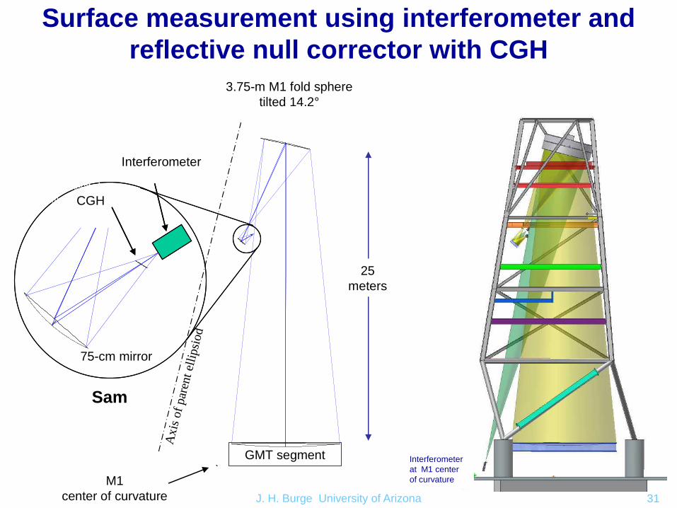
Surface measurement using interferometer and
reflective null corrector with CGH
GMT segment
0.75 m sphere
interferometer
computer-generated
hologram
GMT segment
0.75 m sphere
interferometer
computer-generated
hologram
GMT segment
Interferometer
CGH
3.75-m M1 fold sphere
tilted 14.2°
25
meters
75-cm mirror
Axis
of
par
ent
elli
psi
od
M1
center of curvature
Sam
Interferometer
at M1 center
of curvature
J. H. Burge University of Arizona 32
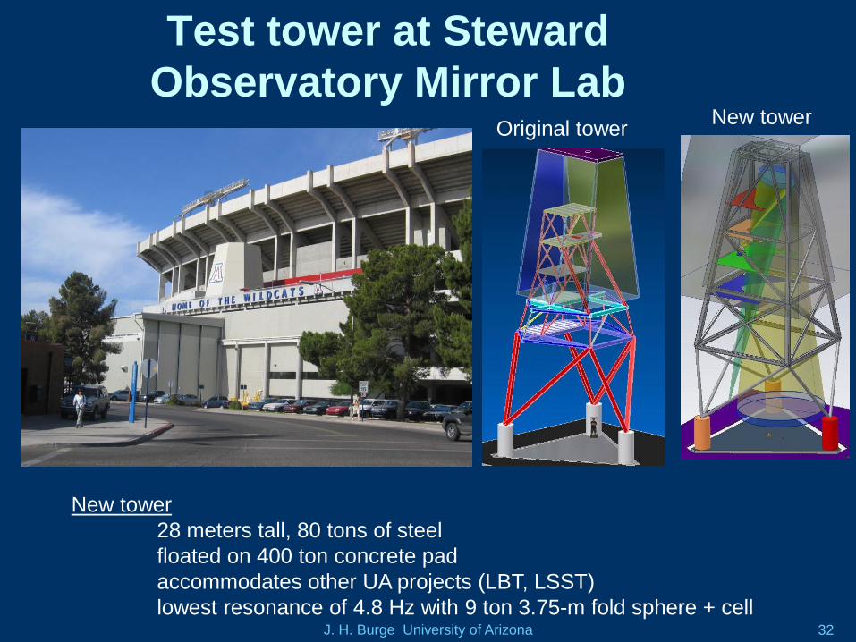
Test tower at Steward
Observatory Mirror LabOriginal tower
New tower
New tower
28 meters tall, 80 tons of steel
floated on 400 ton concrete pad
accommodates other UA projects (LBT, LSST)
lowest resonance of 4.8 Hz with 9 ton 3.75-m fold sphere + cell
J. H. Burge University of Arizona 33
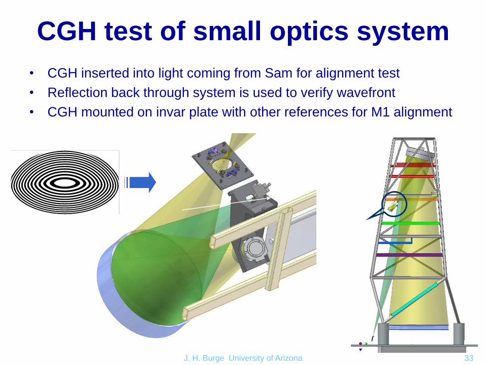
CGH test of small optics system
• CGH inserted into light coming from Sam for alignment test
• Reflection back through system is used to verify wavefront
• CGH mounted on invar plate with other references for M1 alignment

J. H. Burge University of Arizona 34
Active alignment relies on laser tracker
• Reference hologram is aligned to
Sam. Then it is used to represent
Sam.
• Laser tracker used to co-align Sam,
fold sphere, GMT
Laser trackerSphere
Mounted
Retroreflector
Measures to determine
position to ~25 µm
J. H. Burge University of Arizona 35
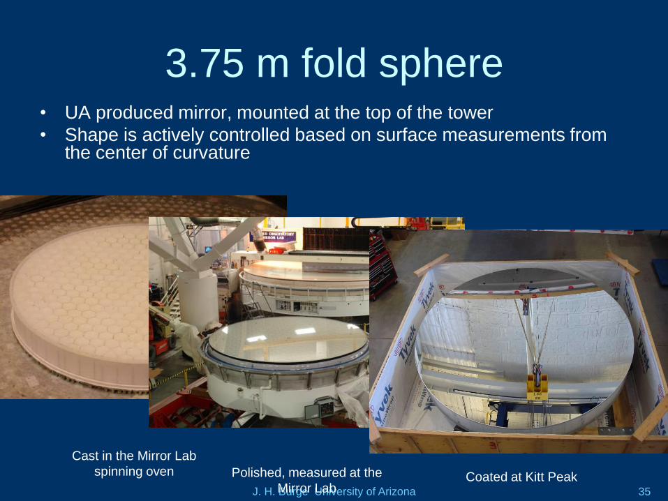
3.75 m fold sphere• UA produced mirror, mounted at the top of the tower
• Shape is actively controlled based on surface measurements from the center of curvature
Polished, measured at the
Mirror Lab
Cast in the Mirror Lab
spinning oven Coated at Kitt Peak
J. H. Burge University of Arizona 36
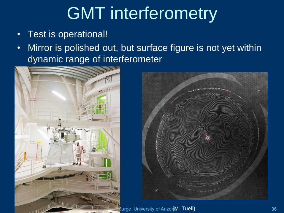
GMT interferometry• Test is operational!
• Mirror is polished out, but surface figure is not yet within
dynamic range of interferometer
(M. Tuell)
J. H. Burge University of Arizona 37
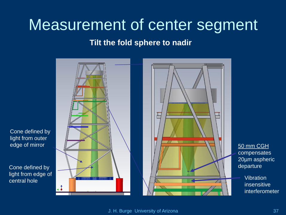
Measurement of center segment
50 mm CGH
compensates
20µm aspheric
departure
Cone defined by
light from outer
edge of mirror
Vibration
insensitive
interferometer
Cone defined by
light from edge of
central hole
Tilt the fold sphere to nadir
J. H. Burge University of Arizona 38
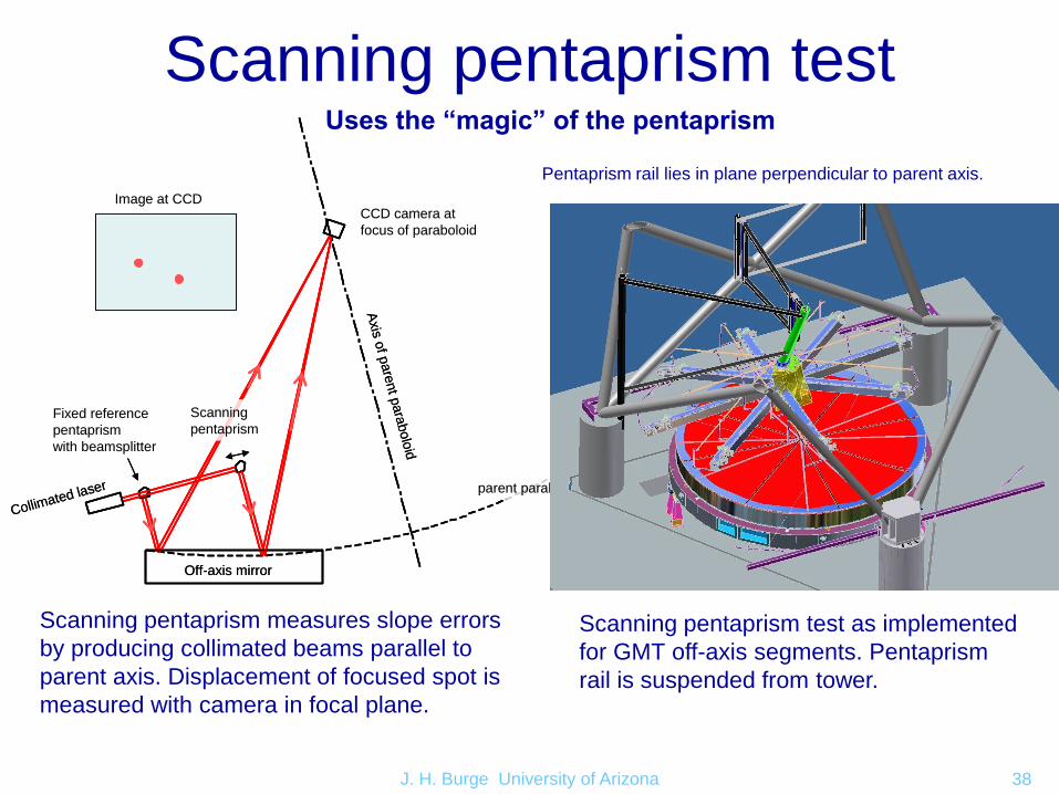
Scanning pentaprism test
Scanning pentaprism measures slope errors
by producing collimated beams parallel to
parent axis. Displacement of focused spot is
measured with camera in focal plane.
Pentaprism rail lies in plane perpendicular to parent axis.
Scanning pentaprism test as implemented
for GMT off-axis segments. Pentaprism
rail is suspended from tower.A
xis
of p
are
nt p
ara
bolo
id
parent paraboloid
Off-axis mirror
Collimated laser
CCD camera at
focus of paraboloid
Fixed reference
pentaprism
with beamsplitter
Scanning
pentaprism
Image at CCD
Axis
of p
are
nt p
ara
bolo
id
parent paraboloid
Off-axis mirror
Collimated laser
CCD camera at
focus of paraboloid
Fixed reference
pentaprism
with beamsplitter
Scanning
pentaprism
Image at CCD
Uses the “magic” of the pentaprism
J. H. Burge University of Arizona 39
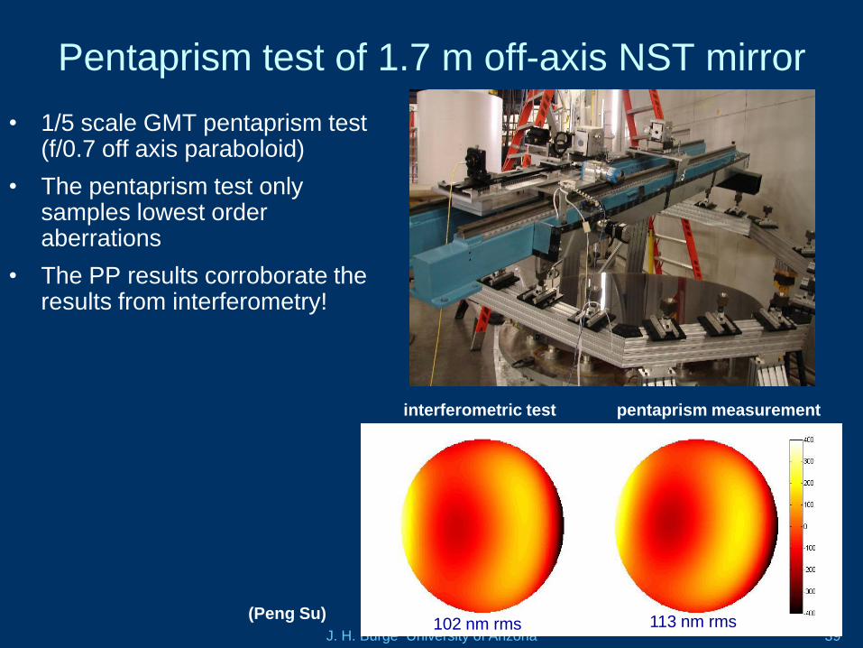
Pentaprism test of 1.7 m off-axis NST mirror
• 1/5 scale GMT pentaprism test (f/0.7 off axis paraboloid)
• The pentaprism test only samples lowest order aberrations
• The PP results corroborate the results from interferometry!
pentaprism measurementinterferometric test
nm
surface
102 nm rms 113 nm rms(Peng Su)
J. H. Burge University of Arizona 40
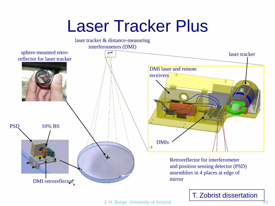
sphere-mounted retro-
reflector for laser tracker
Retroreflector for interferometer
and position sensing detector (PSD)
assemblies in 4 places at edge of
mirror
laser tracker & distance-measuring
interferometers (DMI)
PSD 10% BS
DMI retroreflector
DMI laser and remote
receivers
laser tracker
DMIs
Laser Tracker Plus
T. Zobrist dissertation
J. H. Burge University of Arizona 41
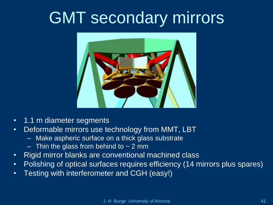
GMT secondary mirrors
• 1.1 m diameter segments
• Deformable mirrors use technology from MMT, LBT– Make aspheric surface on a thick glass substrate
– Thin the glass from behind to ~ 2 mm
• Rigid mirror blanks are conventional machined class
• Polishing of optical surfaces requires efficiency (14 mirrors plus spares)
• Testing with interferometer and CGH (easy!)
J. H. Burge University of Arizona 42
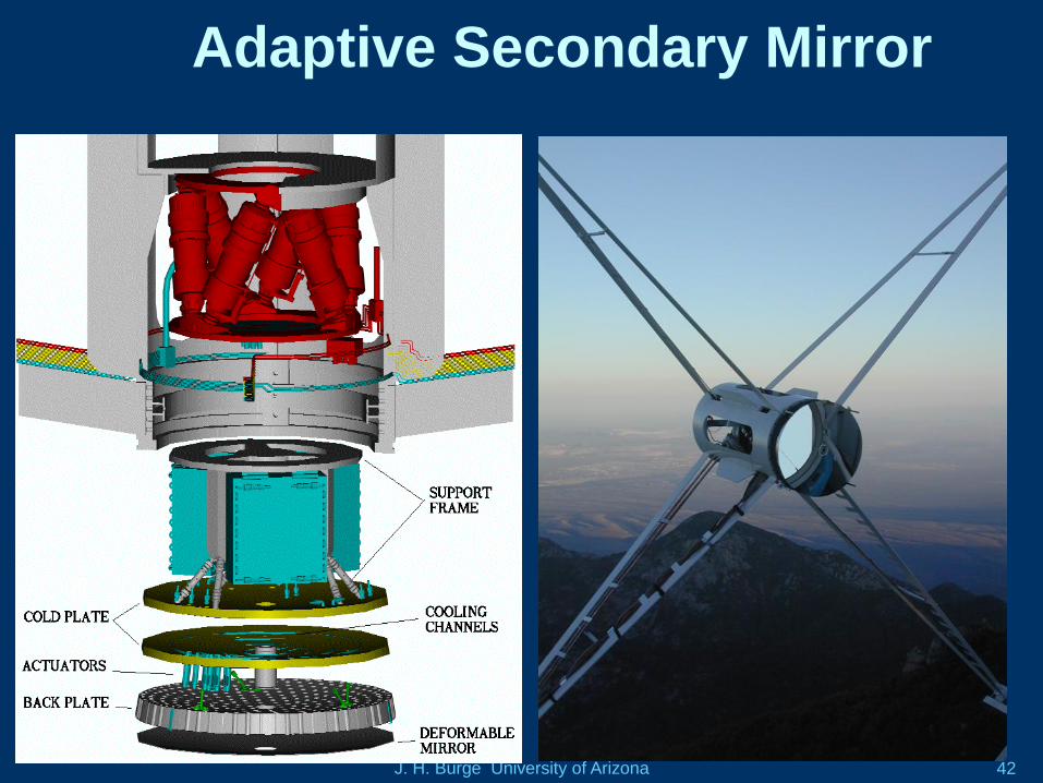
Adaptive Secondary Mirror
J. H. Burge University of Arizona 43
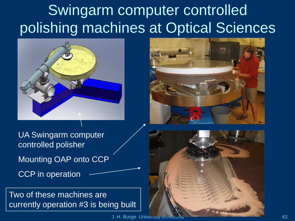
Swingarm computer controlled
polishing machines at Optical Sciences
UA Swingarm computer
controlled polisher
Mounting OAP onto CCP
CCP in operation
Two of these machines are
currently operation #3 is being built
J. H. Burge University of Arizona 44
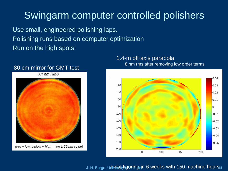
Swingarm computer controlled polishers
80 cm mirror for GMT test43 terms removed,Fizeau map rms=0.0083898um
50 100 150 200
20
40
60
80
100
120
140
160
180
200
-0.05
-0.04
-0.03
-0.02
-0.01
0
0.01
0.02
0.03
0.04
1.4-m off axis parabola8 nm rms after removing low order terms
Use small, engineered polishing laps.
Polishing runs based on computer optimization
Run on the high spots!
Final figuring in 6 weeks with 150 machine hours
J. H. Burge University of Arizona 45
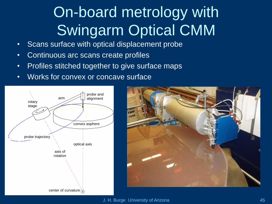
On-board metrology with
Swingarm Optical CMM• Scans surface with optical displacement probe
• Continuous arc scans create profiles
• Profiles stitched together to give surface maps
• Works for convex or concave surface
probe and alignment stages
convex asphere
center of curvature
optical axis
axis of rotation
probe trajectory
rotary stage
arm
J. H. Burge University of Arizona 46
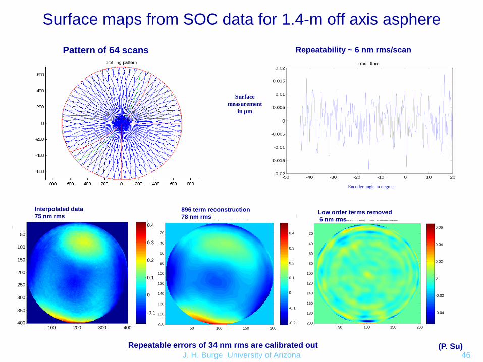
Surface maps from SOC data for 1.4-m off axis asphere
Pattern of 64 scans
Interpolated data
75 nm rmsGrid map rms=0.07471um
100 200 300 400
50
100
150
200
250
300
350
400
-0.1
0
0.1
0.2
0.3
Grid map power removed rms=0.07245um
100 200 300 400
50
100
150
200
250
300
350
400
-0.1
0
0.1
0.2
0.3
0.4
Grid map power astigmatism and coma removed rms=0.031665um
100 200 300 400
50
100
150
200
250
300
350
400
-0.1
-0.05
0
0.05
0.1
0.15
4 terms removed, rms=0.07857um
50 100 150 200
20
40
60
80
100
120
140
160
180
200 -0.2
-0.1
0
0.1
0.2
0.3
0.4
896 term reconstruction
78 nm rms43 terms removed, rms=0.0065192um
50 100 150 200
20
40
60
80
100
120
140
160
180
200
-0.04
-0.02
0
0.02
0.04
0.06
Low order terms removed
6 nm rms
(P. Su)
-50 -40 -30 -20 -10 0 10 20-0.02
-0.015
-0.01
-0.005
0
0.005
0.01
0.015
0.02rms=6nm
Encoder angle in degrees
Repeatability ~ 6 nm rms/scan
Surface
measurement
in µm
Repeatable errors of 34 nm rms are calibrated out
J. H. Burge University of Arizona 47
The Giant Magellan Telescope
• Uses proven mirror technology
• Challenge of optical testing is being solved
• Challenge of rapid fabrication for
secondary mirrors is solved
• The casting of the second primary mirror
segment is currently being planned
J. H. Burge University of Arizona 48
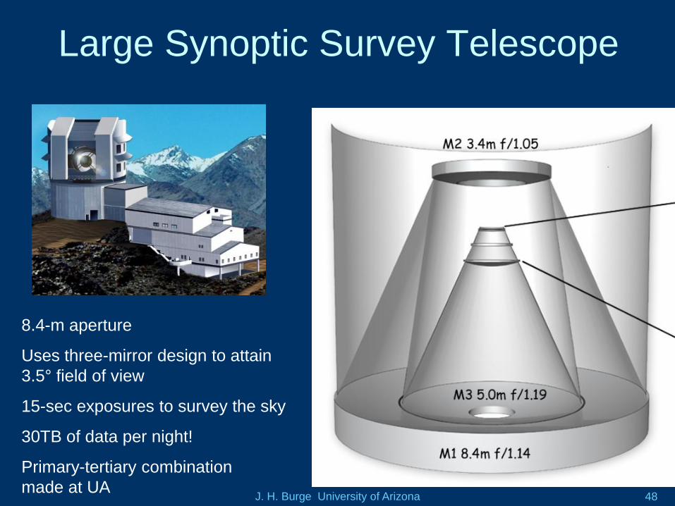
Large Synoptic Survey Telescope
8.4-m aperture
Uses three-mirror design to attain
3.5° field of view
15-sec exposures to survey the sky
30TB of data per night!
Primary-tertiary combination
made at UA
J. H. Burge University of Arizona 49
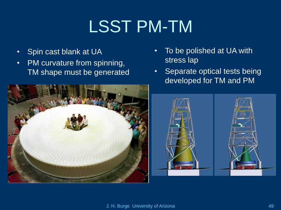
LSST PM-TM
• Spin cast blank at UA
• PM curvature from spinning,
TM shape must be generated
• To be polished at UA with
stress lap
• Separate optical tests being
developed for TM and PM
J. H. Burge University of Arizona 50
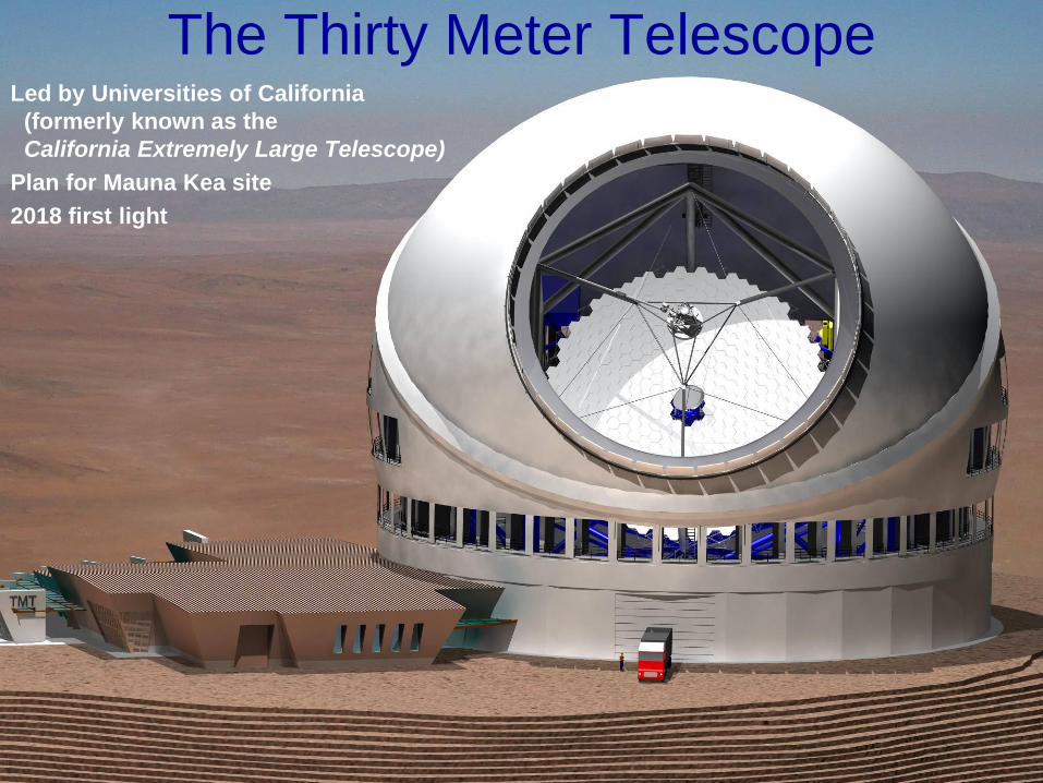
The Thirty Meter Telescope Led by Universities of California
(formerly known as the
California Extremely Large Telescope)
Plan for Mauna Kea site
2018 first light
J. H. Burge University of Arizona 51
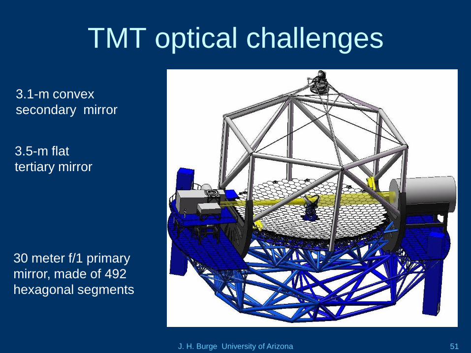
TMT optical challenges
3.5-m flat
tertiary mirror
3.1-m convex
secondary mirror
30 meter f/1 primary
mirror, made of 492
hexagonal segments
J. H. Burge University of Arizona 52
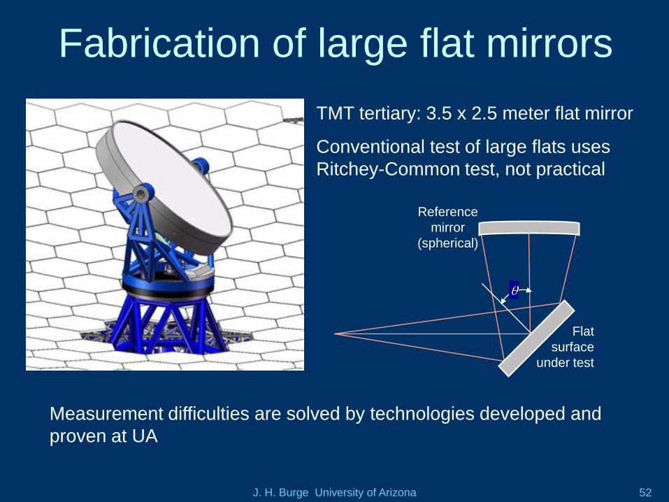
Fabrication of large flat mirrors
Flat
surface
under test
Reference
mirror
(spherical)
TMT tertiary: 3.5 x 2.5 meter flat mirror
Conventional test of large flats uses
Ritchey-Common test, not practical
Measurement difficulties are solved by technologies developed and
proven at UA
J. H. Burge University of Arizona 53
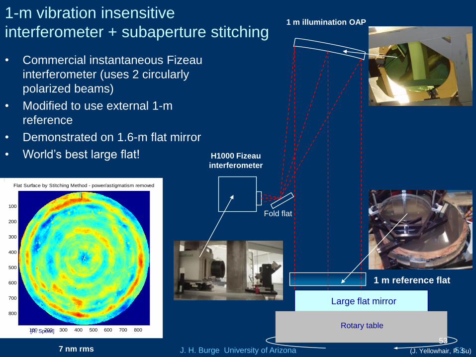
1-m vibration insensitive
interferometer + subaperture stitching
• Commercial instantaneous Fizeau
interferometer (uses 2 circularly
polarized beams)
• Modified to use external 1-m
reference
• Demonstrated on 1.6-m flat mirror
• World’s best large flat!
Large flat mirror
1 m reference flat
H1000 Fizeau
interferometer
Fold flat
1 m illumination OAP
Rotary table
53
Flat Surface by Stitching Method - power/astigmatism removed
100 200 300 400 500 600 700 800
100
200
300
400
500
600
700
800 0.01
0.02
0.03
0.04
0.05
0.06
0.07
0.08
0.09
0.1
7 nm rms
[R. Spowl]
(J. Yellowhair, P. Su)
J. H. Burge University of Arizona 54
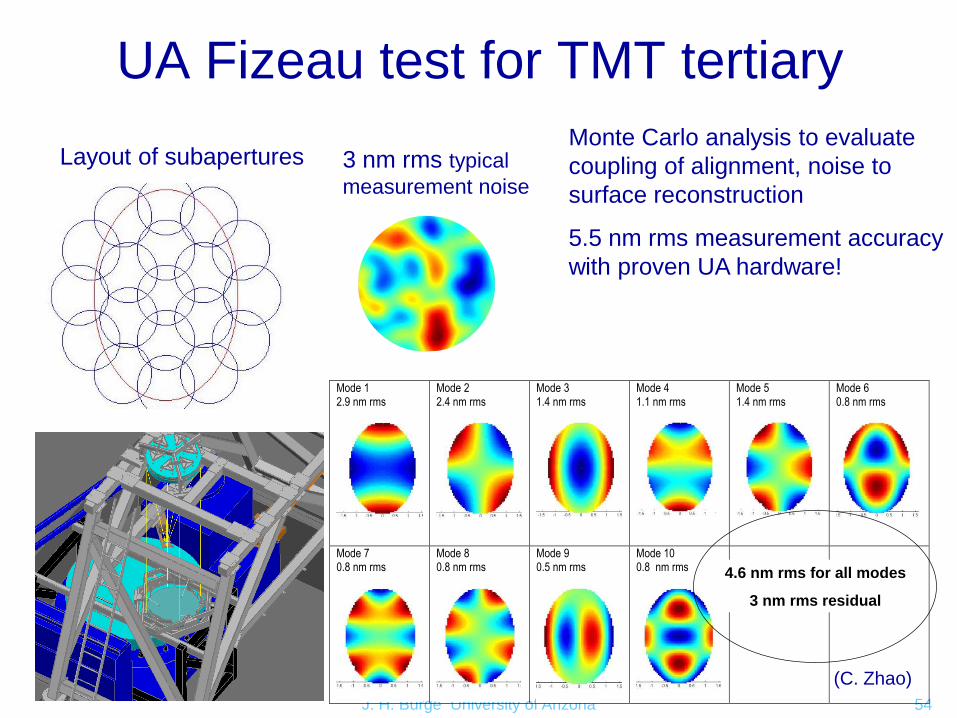
UA Fizeau test for TMT tertiary
Layout of subapertures 3 nm rms typical
measurement noise
Mode 1 2.9 nm rms
Mode 2 2.4 nm rms
Mode 3 1.4 nm rms
Mode 4 1.1 nm rms
Mode 5 1.4 nm rms
Mode 6 0.8 nm rms
Mode 7 0.8 nm rms
Mode 8 0.8 nm rms
Mode 9 0.5 nm rms
Mode 10 0.8 nm rms
RSS for all modes: 4.6 nm rms
Residual from fitting all modes 3 nm rms
4.6 nm rms for all modes
3 nm rms residual
Monte Carlo analysis to evaluate
coupling of alignment, noise to
surface reconstruction
5.5 nm rms measurement accuracy
with proven UA hardware!
(C. Zhao)

J. H. Burge University of Arizona 55
Scanning pentaprism test for flat mirrors
• Demonstrated performance is 2
nrad rms
• Power measurement for 1.6-m
flat was 11 nm rms
Shutters
Autocollimator system
Fixed prism
(reference )
Scanning
prism
Feedback
mirror
Mechanical
supports
Coupling
wedge
ELCOMAT
(Measuring AC)
UDT
(Alignment AC)
(J. Yellowhair)
J. H. Burge University of Arizona 56
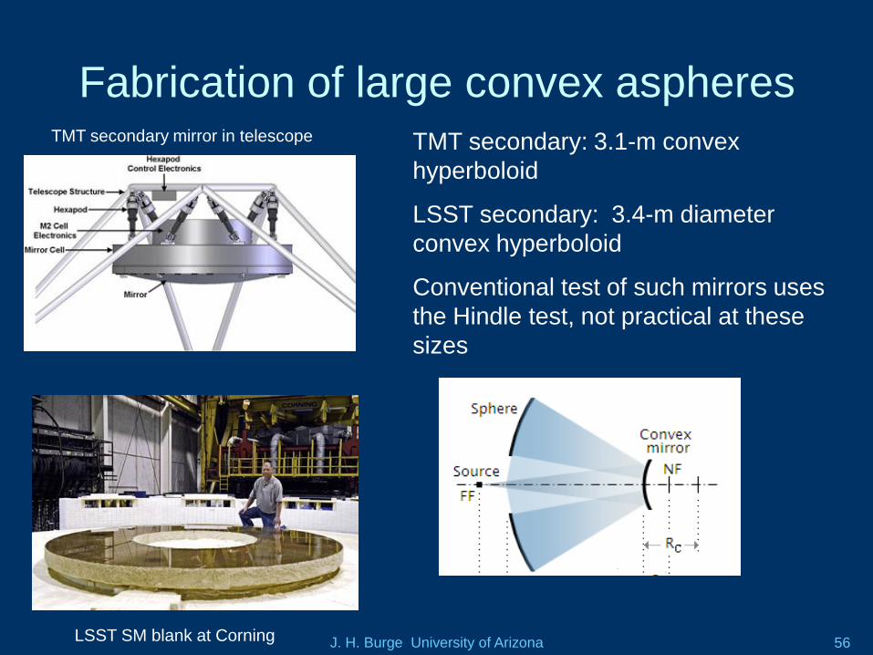
Fabrication of large convex aspheres
TMT secondary: 3.1-m convex
hyperboloid
LSST secondary: 3.4-m diameter
convex hyperboloid
Conventional test of such mirrors uses
the Hindle test, not practical at these
sizes
LSST SM blank at Corning
TMT secondary mirror in telescope
J. H. Burge University of Arizona 57
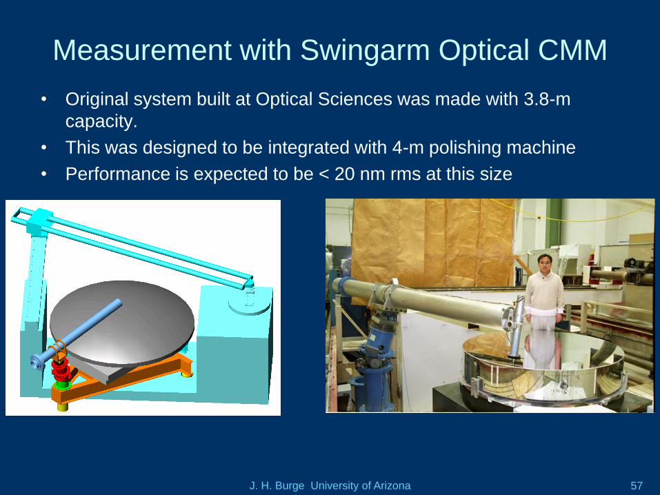
Measurement with Swingarm Optical CMM
• Original system built at Optical Sciences was made with 3.8-m
capacity.
• This was designed to be integrated with 4-m polishing machine
• Performance is expected to be < 20 nm rms at this size
J. H. Burge University of Arizona 58
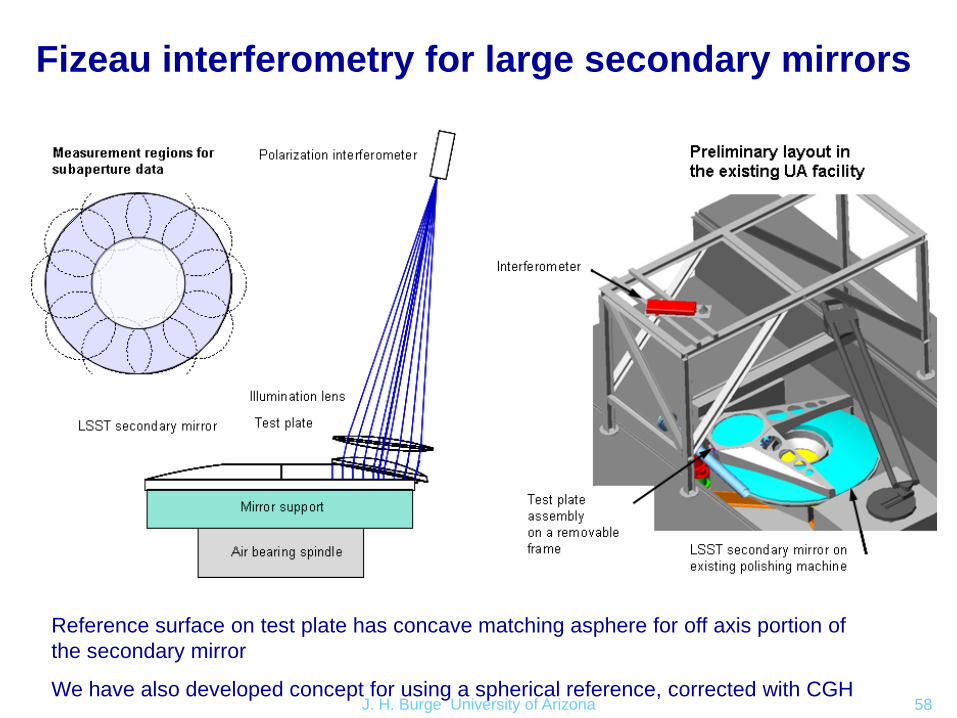
Fizeau interferometry for large secondary mirrors
Reference surface on test plate has concave matching asphere for off axis portion of
the secondary mirror
We have also developed concept for using a spherical reference, corrected with CGH
J. H. Burge University of Arizona 59
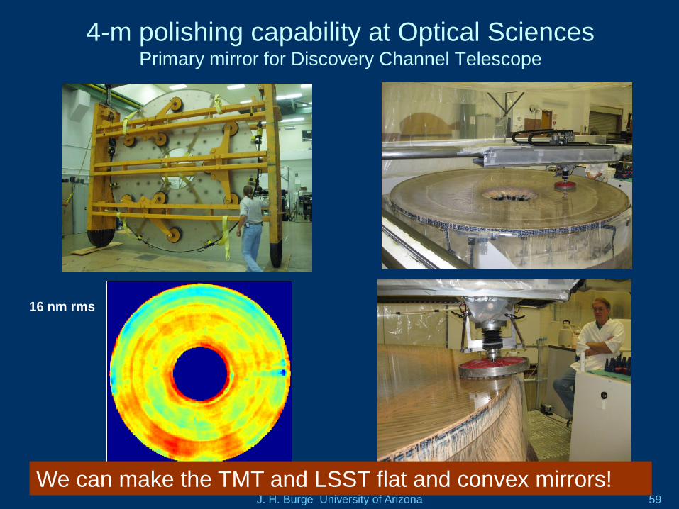
4-m polishing capability at Optical Sciences Primary mirror for Discovery Channel Telescope
16 nm rms
0 50 100 150 200
20
40
60
80
100
120
140
160
180
200
-60
-40
-20
0
20
40
60
80
100
We can make the TMT and LSST flat and convex mirrors!
J. H. Burge University of Arizona 60
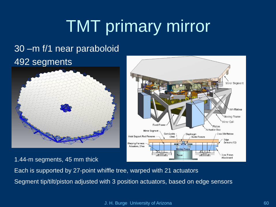
TMT primary mirror
30 –m f/1 near paraboloid
492 segments
1.44-m segments, 45 mm thick
Each is supported by 27-point whiffle tree, warped with 21 actuators
Segment tip/tilt/piston adjusted with 3 position actuators, based on edge sensors
J. H. Burge University of Arizona 61
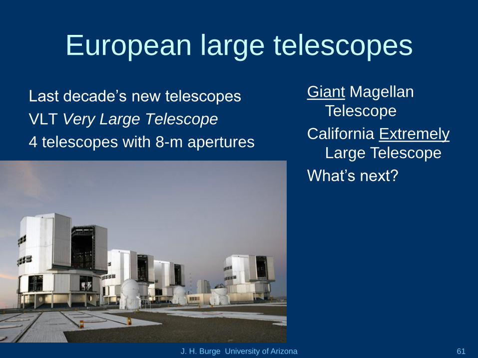
European large telescopes
Last decade’s new telescopes
VLT Very Large Telescope
4 telescopes with 8-m apertures
Giant Magellan
Telescope
California Extremely
Large Telescope
What’s next?
J. H. Burge University of Arizona 62
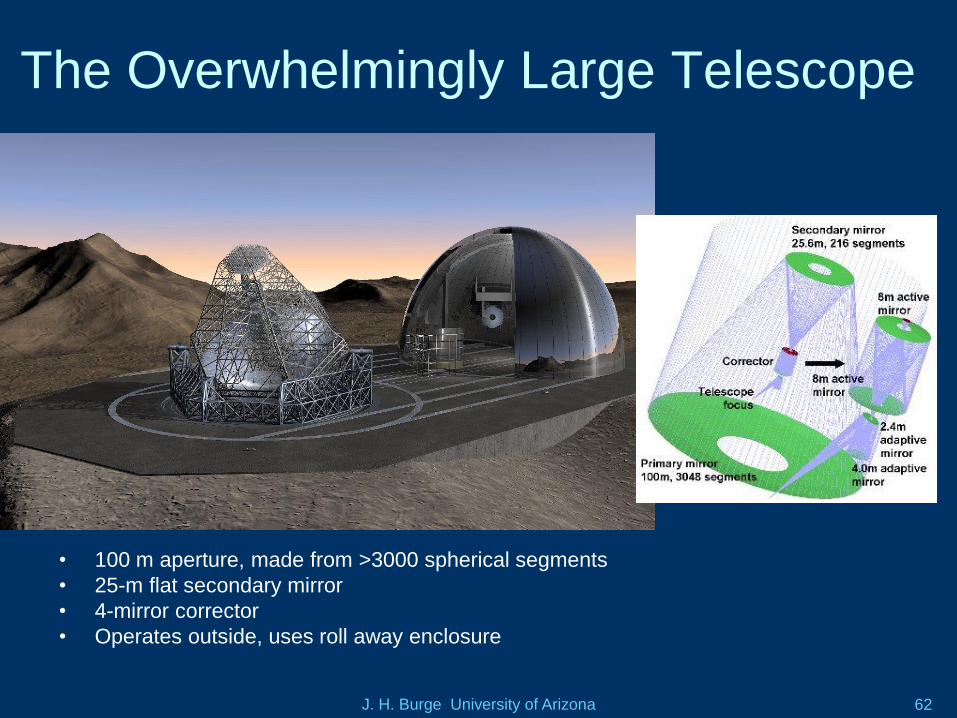
The Overwhelmingly Large Telescope
• 100 m aperture, made from >3000 spherical segments
• 25-m flat secondary mirror
• 4-mirror corrector
• Operates outside, uses roll away enclosure
J. H. Burge University of Arizona 63
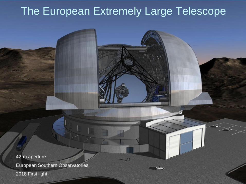
The European Extremely Large Telescope
42-m aperture
European Southern Observatories
2018 First light
J. H. Burge University of Arizona 64
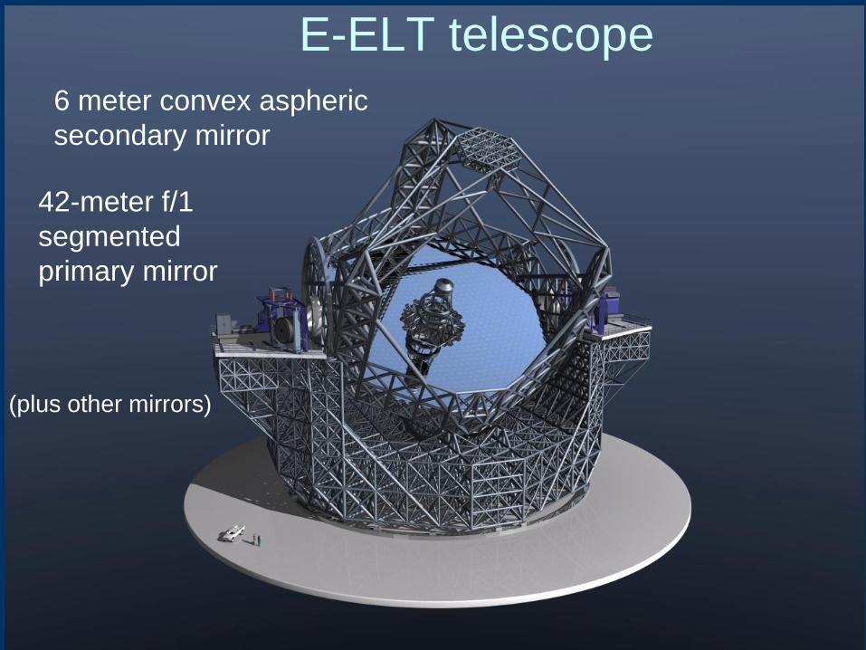
E-ELT telescope
6 meter convex aspheric
secondary mirror
42-meter f/1
segmented
primary mirror
(plus other mirrors)
J. H. Burge University of Arizona 65
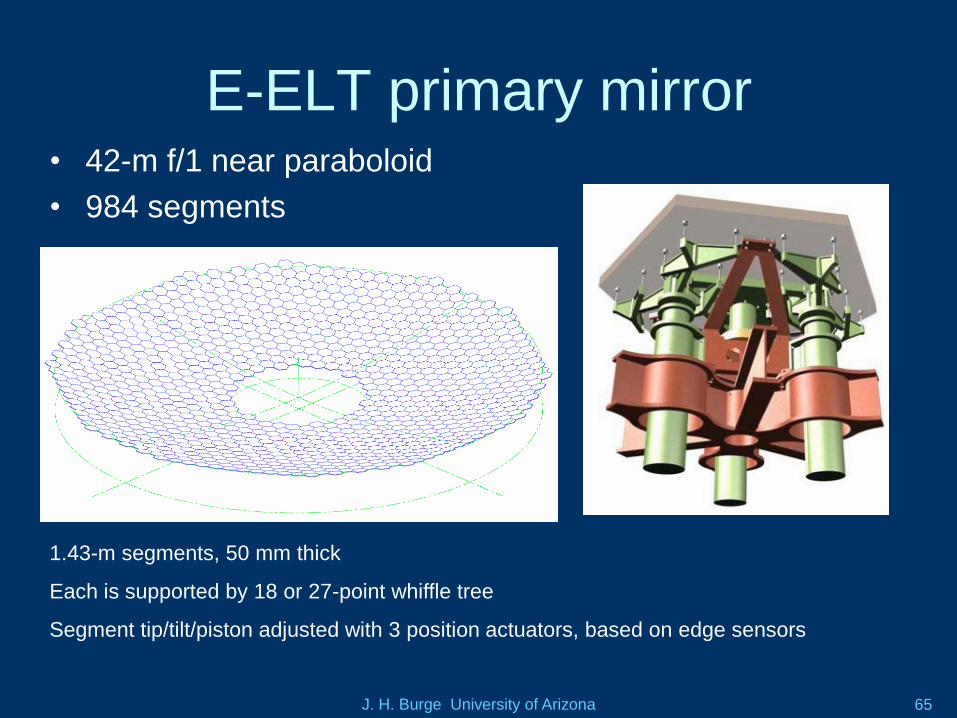
E-ELT primary mirror• 42-m f/1 near paraboloid
• 984 segments
1.43-m segments, 50 mm thick
Each is supported by 18 or 27-point whiffle tree
Segment tip/tilt/piston adjusted with 3 position actuators, based on edge sensors
J. H. Burge University of Arizona 66
The challenges of mirror segments
• Measurement of the surface
– Off-axis aspheres, with different prescription (curvature changes from center to edge)
– To work together, the radius of curvature must match
• Efficient fabrication of hundreds of parts
• Support and operational control of thousands of degrees of freedom
J. H. Burge University of Arizona 67
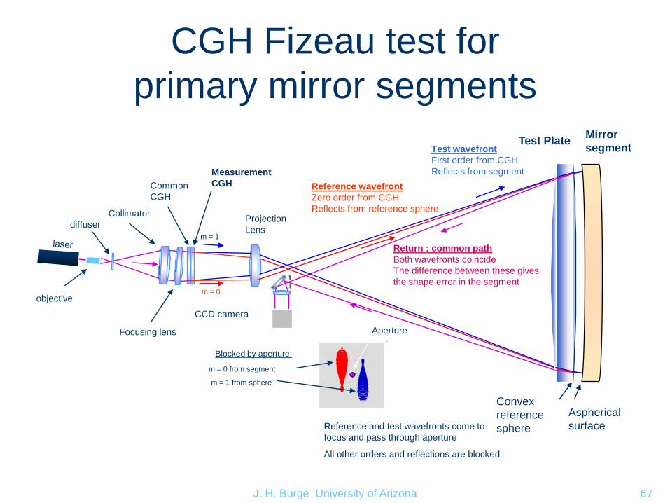
CGH Fizeau test for
primary mirror segments
Collimator
Measurement
CGH
Projection
Lens
CCD camera
Aperture
Reference wavefront
Zero order from CGH
Reflects from reference sphere
Test wavefront
First order from CGH
Reflects from segment
Return : common path
Both wavefronts coincide
The difference between these gives
the shape error in the segment
Common
CGH
Convex
reference
sphere
m = 1
m = 0
m = 0 from segment
m = 1 from sphere
Blocked by aperture:
Reference and test wavefronts come to
focus and pass through aperture
All other orders and reflections are blocked
Mirror
segment
Aspherical
surface
Focusing lens
objective
diffuser
Test Plate
J. H. Burge University of Arizona 68
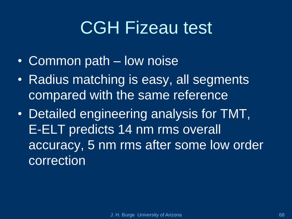
CGH Fizeau test
• Common path – low noise
• Radius matching is easy, all segments
compared with the same reference
• Detailed engineering analysis for TMT,
E-ELT predicts 14 nm rms overall
accuracy, 5 nm rms after some low order
correction
J. H. Burge University of Arizona 69
OAP
Collimator
Measurement
CGH
Lens
CCD camera
Common
CGH
Aspheric
surface
m = 1
m = 0
m = 0 from OAP
m = 1 from sphere
Blocked by aperture:
Reference
sphere
Spherical
surface
objective
diffuser
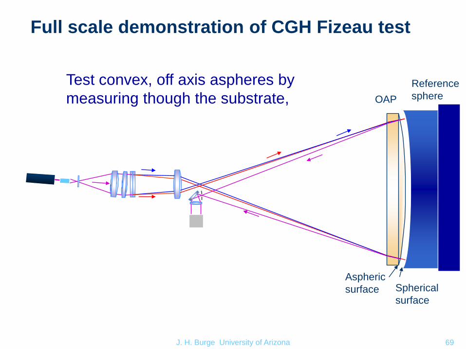
Full scale demonstration of CGH Fizeau test
Test convex, off axis aspheres by
measuring though the substrate,
J. H. Burge University of Arizona 70
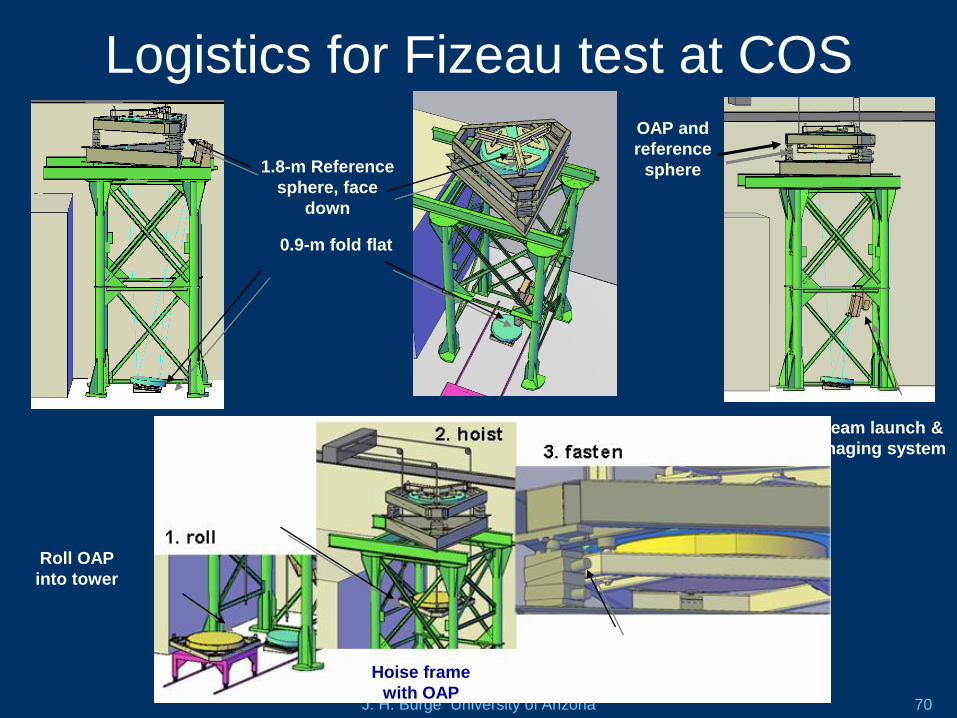
Logistics for Fizeau test at COS
1.8-m Reference
sphere, face
down
Beam launch &
imaging system
0.9-m fold flat
OAP and
reference
sphere
Roll OAP
into tower
Hoise frame
with OAP
Fasten OAP
into position
J. H. Burge University of Arizona 71
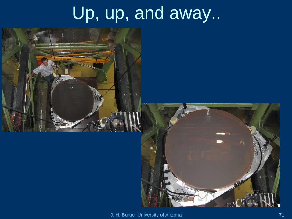
Up, up, and away..
J. H. Burge University of Arizona 72
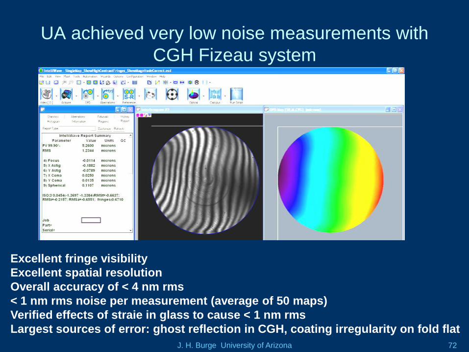
UA achieved very low noise measurements with
CGH Fizeau system
Excellent fringe visibility
Excellent spatial resolution
Overall accuracy of < 4 nm rms
< 1 nm rms noise per measurement (average of 50 maps)
Verified effects of straie in glass to cause < 1 nm rms
Largest sources of error: ghost reflection in CGH, coating irregularity on fold flat
J. H. Burge University of Arizona 73
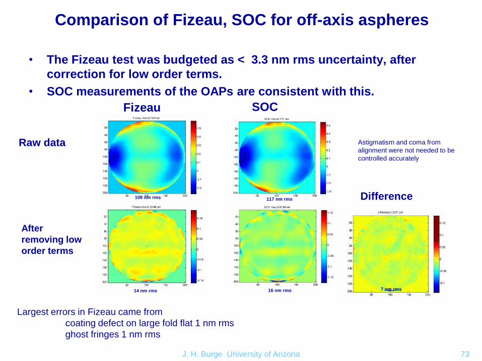
Comparison of Fizeau, SOC for off-axis aspheres
• The Fizeau test was budgeted as < 3.3 nm rms uncertainty, after
correction for low order terms.
• SOC measurements of the OAPs are consistent with this.
Fizeau SOC
Raw data
After
removing low
order terms
Difference109 nm rms 117 nm rms
14 nm rms 16 nm rms 7 nm rms
Largest errors in Fizeau came from
coating defect on large fold flat 1 nm rms
ghost fringes 1 nm rms
Astigmatism and coma from
alignment were not needed to be
controlled accurately
J. H. Burge University of Arizona 74
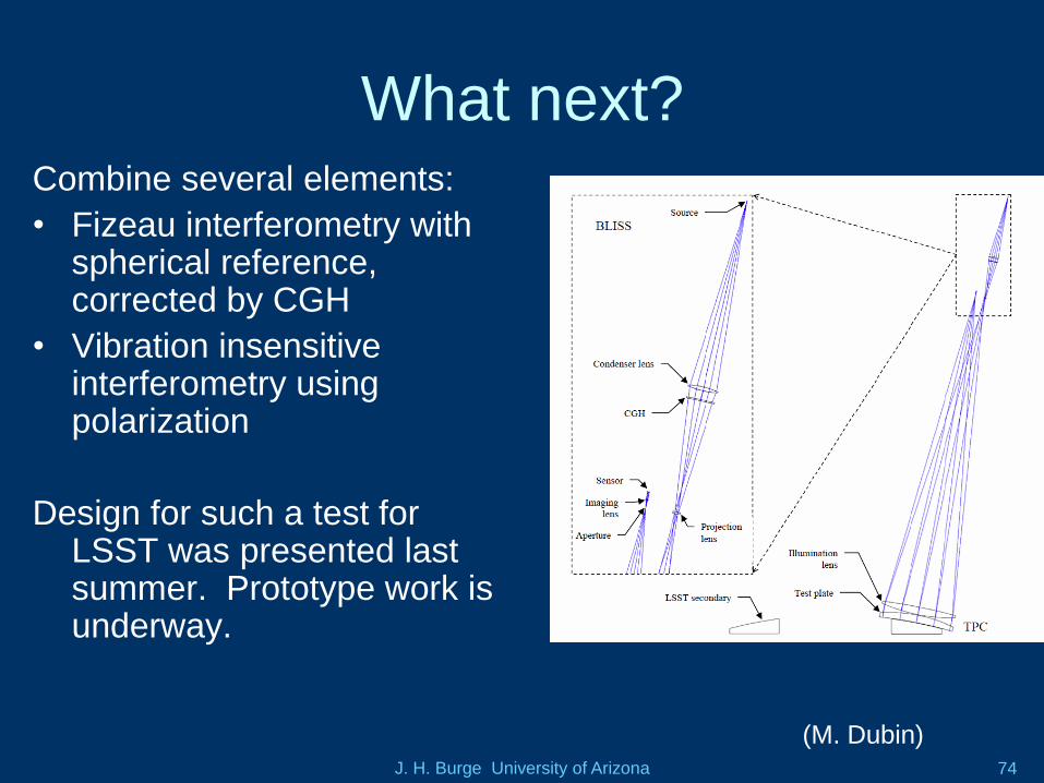
What next?Combine several elements:
• Fizeau interferometry with spherical reference, corrected by CGH
• Vibration insensitive interferometry using polarization
Design for such a test for LSST was presented last summer. Prototype work is underway.
(M. Dubin)
J. H. Burge University of Arizona 75
Conclusion
• University of Arizona technology is
enabling the Giant Magellan Telescope
and the Large Synoptic Survey Telescope
• We are prepared to support TMT, E-ELT if
those projects move forward.

J. H. Burge University of Arizona 76


