MINNESOTA STATE Roofing Design Standards Manual · MINNESOTA STATE Roofing Design Standards Manual...
137
MINNESOTA STATE Roofing Design Standards Manual Limited to: Low-Slope (Dead Level – 2"/ft. slope) Roofs for: New Roof Construction Reroofing Abutting New Construction Reroofing/Roof Repair Tie-ins Associated with Building Renovations Third Edition September 2017 Use only the most current copy of these Design Standards. Most current Edition including revisions can be found at the MnSCU Facilities website. http://www.minnstate.edu/system/finance/facilities/design-construction/resources.html
Transcript of MINNESOTA STATE Roofing Design Standards Manual · MINNESOTA STATE Roofing Design Standards Manual...

MINNESOTA STATE
Roofing Design Standards Manual Limited to:
Low-Slope (Dead Level – 2"/ft. slope) Roofs for:
New Roof Construction
Reroofing Abutting New Construction
Reroofing/Roof Repair Tie-ins Associated with Building Renovations
Third Edition
September 2017
Use only the most current copy of these Design Standards. Most current Edition including revisions can be found at the MnSCU Facilities website.
http://www.minnstate.edu/system/finance/facilities/design-construction/resources.html

Table of Contents
Roof Design Standards 9/17
Introduction
Purpose of the Manual 1
Minnesota State Goal for Roofing Performance 1
Reroofing Design Standards
Part 1A: Reroofing – Predesign Considerations Page
A. Reroofing Existing Roofs Abutting Building Additions 1 B. Interiors 2 C. Roof 3 D. Other 5 E. Follow-up (Post-Field Verification) 6
Part 1A.1: Roof Repairs/Tie-in – Predesign Considerations 6
Part 1B: Roof System
A. Roof System Type 7 B. Roof Assembly Components 8
1. Roof Decks (substrates) 8 2. Vapor Retarder 11 3. Insulation 12 4. Membrane—Surfacing and Base Flashing 13 5. Concealed Flashing (Underlayment) and Sheet Metal Flashing 14 6. Roof Related Wood Blocking 15
C. Drainage 1. Slope/Plan Configuration 15 2. Drainage Types/Materials 16 3. Non-Acceptable Drainage Items 17
D. Roof-Related Items 1. Roof Penetrations 18 2. Mechanical Equipment Support 18 3. No conduit or piping on roof 18 4. Roof Access 18 5. Misc. Roof Items 19
E. Walls Adjacent to Roofs 20 F. Walkways 21 G. Roof Configuration 21 H. Miscellaneous Guidelines 21

Table of Contents
Roof Design Standards 9/17
Part 2: Documents Preparation/Submission and Approval
A. Drawings and Specification Standards 24 1. Roof Plan Standards 24 2. Detail Standards 26 3. Specification Standards 27
B. Construction Cost Estimating 28 C. Design Phase Reviews 28 D. Design Phase Checklist Forms 29
Part 3: Document – Examples
A. Roof Plan Drainage Highlights B. Details C. Sample Specification 1. New Roofing
i. 06 10 05 Roof Related Rough Carpentry ii. 07 51 00 Built-up Bituminous Roofing
iii. Roof Related Sheet Metal Flashings 2. Reroofing
i. 00 73 80 Special Conditions ii. 011000
Appendix A. Roof Resource Information B. Miscellaneous Information
1. Roof Design Standards Revision Process C. Roof Design Standards Revision Form D. Roof Systems Checklist E. Existing Roof Related Field Verification Checklist

Introduction
Purpose of the Manual:
The Roof Design Standards in this manual enables an Architect to design a roof system and produce roof related construction documents for a Minnesota State Standard 40-Year Roof that is associated with a new construction project as follows:
The new roof of the addition or stand-alone building.
Reroofing an existing roof that abuts the new addition.
Reroofing or roof repair tie-in(s) of an existing roof associated with a new building renovation project.
These Roof Design Standards are limited to slope-to-drain roofs with slopes ranging from ¼” per foot to 2” per foot.
Minnesota State Goal for Roofing Performance:
This manual was produced based on experience and expertise in 40-year roof performance. The Roof Design Standards focus on high quality and long-term performance. They are more stringent than industry standards and incorporate cost control, the practicality of installation, the ease of maintenance, and long term sustainability. The Roof Design Standards have been built from a rigorous understanding of how roofs in the northern climate of the United States successfully perform and prematurely fail.
A basic knowledge of roof design is essential in understanding and applying what follows. Further information and additional resources are listed in the appendix.
These standards generally meet building code requirements per this Standard’s Edition date. However, the Architect is responsible for compliance to current building code requirements.
Standards vary from distinct requirements to guidelines as described.
Minnesota State goal for roofs is:
Maximum performance life with the least cost to the taxpayer over the life of the building.
The Minnesota State Standard Roof that has been used and currently meets that goal, for low-slope roofs, is a gravel surfaced four-ply built-up roof with unobstructed positive slope-to-drain.
It’s a time-proven, sustainable, and maintainable roof that will provide 40 years of service life with a low life-cycle cost, when it is properly designed, installed, and maintained.
A brief summary of those three criteria is as follows:
Design: The process of creating clear, comprehensive construction documents using time-tested materials and assemblies following set standards. The roof design consultant should never consider roofing components in isolation, but should always investigate their compatibility with other materials and how it affects the whole system. Roof design requires a high priority in the building design process.
Installation: Construction of the roof to meet the design. Successful construction comes from a qualified roofing contractor, full-time observation and frequent on-site testing, and good communication. Observation and testing addresses construction challenges such as workmanship and weather conditions and provides feedback to the contractor to provide a basis for immediate corrections of any problems. Poor field work accounts for the most roof failures. Minnesota State will contract with a roof consultant to perform full-time observation and testing during construction.

Roof Design Standards 9/17
Maintenance: Once the building is turned over to Minnesota State, proactive preservation of the roof investment, consisting of yearly roof observations with non-destructive techniques (infrared), to document conditions, and if necessary, provide a basis for roof repairs by the Owner.
Additional Information
The following roof-related design work may require the services of sub-consultants: Masonry work (through-wall flashing) Window or skylight transition
Minnesota State will contract with a Roof Design Consultant to perform Peer Review services at the phases of design delineated in Part 2 of these Standards.
Variances request from the roof design standards must be submitted to Minnesota State system office in writing.
Suggested changes or revisions to the Roof Design Standards may be issued to Minnesota State in writing (see appendix).
The appendix provides resources for more information about roofing design and Roof Design Standards revisions. It also includes associated forms and examples of reports, etc.

Roof Design Standards Page 1 9/17
Reroofing Design Standards
Part 1A: Reroofing - Predesign Considerations
A. Reroofing an Existing Roof (ER) Area Abutting a Building Additions
There are several preliminary items and measures that should be taken into consideration prior to starting the design of the existing roof. The make-up and condition of the existing roof system/roof structure is the prime consideration moving into design.
The following Standards address gathering as much as-built conditions information as possible in order to build the best roof design foundation.
Standard ER-1: Original building documents, any associated building addition documents, and any associated reroofing documents are to be obtained and used.
It is important to obtain documents as to how the existing building/roof was intended to be built, actually constructed, or added onto prior to beginning design of the roof on the addition.
Structural and mechanical drawings are important to use and refer to. The structural roof framing plan and details will provide information that addresses roof deck type, span, and connections. Since a built-up roof relies on attachment to the roof deck and separation from adjacent materials at an expansion condition, the structural drawings become a “go to” tool for information.
As a footnote, when the existing roof system has a ballasted single-ply roof membrane, although a mechanically fastened or fully adhered membrane can apply as well, it is very critical to know the expansion conditions in the roof structure. This is important because the gravel surfaced built-up roof cannot span expansion conditions without a strong likelihood of failure. The loose flexible single-ply membrane can typically span expansion situations.
Mechanical drawings usually are referenced early on and quite often for the design of slope-to-drain roof drainage. The location of a building addition could have a major impact on rerouting existing building drainage.
A suggestion for using the various drawings as tools during field verification would be to make copies and create a roof plan packet and roof detail packets, perhaps cut up and put in a field file, so they can be looked at while verifying roof plan/roof system conditions and while verifying roof detail conditions.
Having good original, addition, etc. documents will help save time in the field and will reduce assumptions that could impact a good roof design.
Standard ER-2: Other roof-related documents obtained and used.
Seek out and use other pieces of roof-related information to help to prepare for field verification and subsequent roof design. This may include asbestos reports, mechanical modification information, roof repair information, warranty information (contractor and or roofing manufacturer) and leak history reports (including roofing, associated walls, doors, windows, louvers, mechanical units). This knowledge can set up certain site verification approaches.
Standard ER-3: Determine and confirm sub-consultants for roof work.
Sub-consultant (or in-house approved expert) will be involved in the roof design, from the structural engineer who addresses roof loading along with other roof framing and/or deck system issues, mechanical engineers who address drainage to meet code requirements or if there is mechanical equipment or venting that penetrates the roof, electrical engineers that provide power to roof

Roof Design Standards Page 2 9/17
mounted equipment, masonry consultants when there are roof-related through-wall or wall conditions/concerns, and window consultants if there are roof-related window conditions/concerns.
Sub-consultant are required to provide the same level of thoroughness as the Architect. They are expected to not assume information and follow the Minnesota State Facilities Design Standards.
Standard ER-4: Determine and confirm a roofing contractor for field verification work.
A roofing contractor is strongly recommended for making test openings in the existing roof system and at detail conditions. They are to properly repair the test openings as well. Their work is to be included in the Architect’s fee.
They will need a few days advance notice and they will want to know what type of roof system or systems and roughly the type of roof details they are going to be cutting into and repairing.
Sub-consultants may want to have a contractor make and repair test openings. Confirm with the sub-consultant(s).
Standard ER-5: Inform the campus personnel of upcoming field verification work.
Field verification work will require assistance from certain campus personnel such as those who to can assist with access to and from the roof area(s), and those who has specific building knowledge (including asbestos reports, site features, etc.) and understand the roof leakage and repair history. Campus facility contact names and numbers can be obtained from Minnesota State system office, Facilities Design and Construction. Provide the contact person ample time to prepare for the upcoming field verification work.
The fieldwork activities can cause disruption such as noise. Discuss this with facility personnel and coordinate to minimize or avoid disruption.
The Architect, sub-consultants, and contractors are to follow the facility rules and be good guests. Many times classes will be occurring and students will be present. Exercise safety, cleanliness, and professionalism. Inform the facility personnel when you are off the roof and leaving the site.
Standard ER-6: Determine the approach and general impact/risk of test openings based on the information gathered.
Have a game plan with a contingency. Think about how to get the most information with the least disruption/destruction. Discuss the test openings required by the sub-consultants. Avoid risk; for example, do not plan a test opening in an area that shows evidence of ponded water. Determine the safest places to conduct test openings. See Part 1A.C. for further test opening information.
B. Interiors
Standard ER-7: Document interior conditions.
What is happening inside the building is very important to the design of the existing roof, if applicable and has a major effect on the transitions between the new and existing building. Looking inside can provide information such as humidity conditions, evidence of water entry from the roof, confirmation of building expansion, and as-built conditions related to fire rating and energy analysis.
The Field Verification Worksheet found in the Appendix is a type of form that can be used to check into interior issues and document the results.
The interior information comes from facility personnel and from basic exploring/observing. Often times a ceiling will need removal (a portion) to observe deck conditions/connections and mechanical

Roof Design Standards Page 3 9/17
conditions. Sub-consultants may have special needs for opening up interior walls/ceilings/floors in order to verify as-built conditions. Proper repairs are expected.
Photographs are an invaluable documentation tool.
Observing/documenting interior water entry locations often times relates to a failed condition on the roof. For example, water entry near the outside wall of a classroom can often spell out a problem with a failed roof edge flashing. However, sometimes interior water entry is not related to the roof. For example, a leaky pipe in the ceiling or a failed through-wall flashing in an adjacent wall that is above a roof area.
Identify and test for asbestos-containing materials that will be impacted by the roofing project. The asbestos sub-consultant is to address this, however, the Architect will need to get the ball rolling. Common interior asbestos aspects related to reroofing are drain (bowl and leader) wrap and deck/structure fireproofing.
C. Roof:
Exercise caution, safety, and common sense when accessing and working on the roof. Roofing accidents can happen easily and height is a killer. Varying wind, temperature, and other conditions must be considered when working on roofs. Rooftop work is vital. See Minnesota State if unable to perform the field verification portion and they will assign someone to do the work and the Architect’s fee will be reduced accordingly.
Standard ER-8: Perform roof system test cuts and document conditions using forms, sketches, and photographs.
The expectation is one roof system opening per roof vintage, per roof deck type and per roof system type. The Field Verification Worksheet form, located in the Appendix, is a type of form used to document the observed conditions. Test openings are typically 4" to 6" square and go down to (not through) the roof deck.
It is important to discuss what is actually seen and avoid assumptions. A roofing contractor can provide helpful information. If some components are unknown, take a sample, bring it back to the office, and evaluate it.
Salvaging the existing roof membrane isn’t likely to happen, nor is salvaging the existing insulation (unless its type and condition warrants reuse). However, it is important to know for the design process the types of materials and the insulation thickness and overall condition.
Determining if an existing vapor retarder is present is helpful, but not critical because it will likely be removed. The most critical component to verify/document is the existing roof deck, including its type, thickness, condition, and what is attached to it (felt, asphalt, pitch, adhesive, etc.). The new built-up roof will be attached to the existing roof deck and the reroofing system attachment approach/method relates to the deck aspects.
A concrete deck that is unprimed will need to be primed in order to properly accept hot asphalt. Often times, a single-ply roof system installed as a first roof system on a building, will not have a primed concrete deck.
A photograph and a graphic sketch are required at each test opening. Do not assume anything.

Roof Design Standards Page 4 9/17
Standard ER-9: Perform roof detail test cuts and document conditions using forms, sketches, and photographs.
The expectation is one test cut per each detail condition per each roof vintage. Test cuts typically include the removal of sheet metal, systematically removing flashings, membrane and adjacent insulation, followed by full dimensioning of exposed conditions. Sometimes further material removal is required, such as wood blocking, in order to confirm anchorage, stability, and salvage ability. Test cuts typically are 4" to 6" wide; however, they can vary in size quite a lot.
Having the original detail to look at during test opening work can help to better understand what is happening and can help to save time and avoid guessing. The as-built condition can also be sketched on a detail copy if the detail is at least at 1 1/2" = 1'0" scale.
Sometimes more than one test cut per each detail condition per each roof vintage is required. This would occur when the original drawings (and/or visual observations) indicate a different type of roof deck, or a unique roof deck condition. Another reason would be to double check a detail condition that represents a large quantity of a roof condition such as a roof edge.
An example of a unique roof deck condition would be a long-span double T precast concrete deck, which is typically pinned at the bearing condition and not pinned at the non-bearing condition. A test cut at each condition would be necessary.
At times, a minimal detail test opening is acceptable. This is only considered when certain criteria are met, such as the detail represents a relatively insignificant cost of the project and the visual observation leaves little to speculate, a minimal opening can mean a sample test cut or a probe with a screwdriver.
Sketching the as-built detail condition is required and it should be clear to read, have all dimensions, materials called out and labeled. An example is included in the Appendix. It is the foundation of the detail design and it will later be developed into a detail packet.
Two photographs are required at each detail test opening. Include a tape measure as part of a close up photo (approximately 18" to 24" away) and a context photo (approximately 3' to 6' away).
Check to see that the roofing contractor has patched all detail test cut openings before leaving the roof.
The Field Verification Worksheet, included in the Appendix, has some helpful items to address regarding detail conditions. Space is provided to document.
Standard ER-10: Document all features on the existing roof, if it is to be replaced.
The following are some examples:
1. Determine the depth and area of ponded water. This information used in conjunction with the original/existing structural roof framing drawing will help to determine what insulation slope will be needed to accurately eliminate the ponding.
2. Locate and document all roof penetrations and indicate their sizes and uses. This information will be important when laying out drainage solutions during design and will need to be shown on the roof plan. This will allow the roofing contractor to properly estimate construction time and cost.
3. Identify obsolete items. This could include ones that appear obsolete and ones that have been indicated to be eliminated. Verify information with building personnel.
4. Locate existing drainage devices and determine their size. This includes scuppers, roof drains, primary and overflow.

Roof Design Standards Page 5 9/17
5. Perform a test opening at a representative roof drain to determine its height above the existing roof deck.
6. Identify if the roof drain has its components present such as a clamping ring, all clamping bolts, and a drain screen.
7. If the roof drain has a control flow collar, it needs to be documented since that indicates control flow drainage design.
8. If the roof drain is installed with a leaded connection to the leader that should be documented. The leaded drain is typically replaced since they are usually over 20 years and they can lead to leakage problems from the reroofing construction work.
9. Verify any deck slope. As a note, any roof slope over 1"/foot will require special design and construction.
10. Document penthouse features, including location, height, wall flashing, door and louver detailing at the roof, and conditions including related leakage.
11. Document existing mechanical and electrical piping that is resting on/penetrating the roof. These will need to be relocated off the roof (typically to the building interior). See Standard 1-36.
12. The asbestos sub-consultant is to identify, sample, and test roof material and roof related material (such as under deck fireproofing, drain bowl, and leader line pipe wrap) for asbestos. The Architect needs to get this ball rolling and coordinate this rooftop activity with a roofing contractor (for repairs to test sites).
13. Hot pipe, heat stacks, generator relief vents, or pipes are vital to identify and discuss with campus. The campus contact should provide you with the temperature information.
Standard ER-11: Document features adjacent to the roof.
The following are some examples:
1. Walls, including windows, louvers, and doors, may not be constructed to Minnesota State Design Standards. Document through-wall conditions at adjacent masonry surfaces. Look for flashing material coming out of the wall and/or rope wicks, or other drainage devices. Understand the height of the through-wall above the roof deck along with the sill elevations and physical features and conditions of the windows, louvers, and doors. Having existing details to look at and compare to the as-built conditions is very helpful in determining a design resolution. Suspect wall, window, and louver conditions will require further field verification. See Minnesota State Facilities Design Standards for further guidelines.
2. Locate drain discharge piping and scupper downspouts impacting the roof. How much water discharges onto the roof is important to gather. Document the size of the drain/downspout and the roof area (in square feet) they drain.
3. Verify roof deck elevations and the wall conditions of adjacent higher roofs. Besides the through-wall identification, it is important to understand if wall deficiencies could contribute to the premature failure of the roof. These deficiencies will need to be repaired or the wall could be covered with new materials.
D. Other
Standard ER-12: Document features impacting the roof/roofing project.
The following are some examples:
1. Document existing site conditions and/or ground information. This would relate to the contractor accessing the roof and staging/storage of their materials. This information comes

Roof Design Standards Page 6 9/17
from existing building drawings, discussions with the facility person, and generally observing/documenting surface and vegetation conditions.
2. Roof access, such as a low roof to a high roof, sometimes is inadequate and/or the facility person wants some access improvement. Discuss with the facility person and look for ways to improve roof access to the roof being designed or to another adjacent roof.
3. Document any adjacent roofs that discharge water, snow, and/or ice directly onto the roof.
4. Photograph/explore the roof perimeters, especially at roof elevation changes or at intersections of different roof vintages, via exterior elevation photos and interior observations for signs of building expansion that might not have shown up on the roof.
Expansion joints in the floor and at connections of different masses/vintages of the building are a good sign that the roof may be expanding/contracting.
E. Follow-up (Post-Field Verification)
Standard ER-13: Organize field information and correlate roof plan information with original documents such as a structural roof framing plan and mechanical (HVAC and pluming) plans.
This creates a basis for designing roof drainage. The information will guide the progress and speed it up as well. Include organized photos that are overall in nature.
Standard ER-14: Create detail packets of information.
Similar to Standard RR-13, this organization will guide the design work to come. The detail sketch gives a log of “as-built” information and the original detail gives the intent of the original design. The structural connection detail provides important “connection” information. All together they guide the designer in designing solutions.
Standard ER-15: Complete all checklists and sketches; establish photo associations to field information.
It is important to finish/clean up the work that can often times be unfinished while on the site. Weather conditions, the lack of time, etc. can cause incomplete information. Organize this information and set a plan for focused accurate non-assumption based design, in a time frame close to the on-site work.
Part 1A.1: Roof Repairs/Tie-In - Predesign Considerations A. Many of the ER Standards are to be followed, however, there may be only a few of them
that actually apply based on the specifics of the actual project. An additional Standard is as follows:
Standard ER-16: Confirm if the existing roof is a Minnesota State Standard Roof It is critical to understand if the existing roof system is a Minnesota State Standard Roof as it required to remain as such after the roof repair or roof system tie-in construction is complete. Consult Minnesota State to determine if the existing roof system is a Minnesota State Standard Roof. Existing warranties must remain (not be voided) with any of the project activities (during design, and during construction). Tie-in detail examples are included in Part 3.

Roof Design Standards Page 7 9/17
Part 1B: Roof System
A. The Roof System Type
Standard 1-1: A gravel-surfaced 4-ply built-up roof as further outlined in these design standards.
This type of roof has an excellent track record of performance in this state, for this type of building. Twenty years of performance is very common and 40-year performance occurs with the right combination of design, installation, and maintenance. It is a durable roof, fairly easy to maintain, has a low life cycle cost, is sustainable and can have significant material salvage ability when reroofed. It provides a Class A external fire rating.
A key to the success of this roof system is attachment of the roofing materials. The Roof Design Standards will address attachment, as it is key to transferring membrane stresses to the substrate. Without that attachment and transfer, membrane (and flashings) develops splits, ridges, etc. and the roof will fail.
The built-up roof, when attached properly, reflects the building’s structural characteristics, therefore, it is critical to understand the substrate (see B-1, Roof Decks).
Standard 1-2: 10 years of satisfactory performance history for key components (materials) is required to establish long-term roof system success.
Roofing components have and will change, and when they do the test of time is necessary to confirm their performance. Not all materials require 10 years of experience, however, 10 years is required for key system components, such as the insulation.
Standard 1-3: Use minimum R-35 roof insulation throughout the State of Minnesota.
Projects receiving state funding are required to follow the SB2030 Energy Standards for all new construction or major renovations projects. The SB2030 Energy Standard has the state divided into two climate zones. To simplify roof designs, Minnesota State requires all roofs be insulated to comply with the R-value for climate zone 7.
Standard 1-3a: Minimum 2” Insulation Thickness at Roof Drains
The amount of insulation at the roof drain can vary in order to accommodate the primary and secondary roof drainage solution, however, a thickness less than 2” makes the roof drain installation difficult to install properly and the insulation R-value gets to be too low.
It is important to have a small steeper-sloped insulation sump and a 3’ x 3’ flat spot centered at the roof drain (see Part IB, C. Drainage).
Standard 1-3b: Averaging R-Value in the Roof System
The State Plan Reviewers allow and Minnesota State prefers averaging the R-value of a fully tapered insulation system. However, if the MN State Energy Code compliance method used is IECC 2012, it is recommended that the local building official review for approval. See Staff Interpretation from the MN Department of Labor and Industry dated 3-1-16 in the Appendix.
If the MN State Energy Code compliance method ASHRAE 90.1-2010 is used, Section 5.5.3(b) requires a maximum U-factor for the entire assembly (indicates that the insulating value of the roof can be averaged over the entire roof assembly).

Roof Design Standards Page 8 9/17
B. Roof Assembly Components
See Part 3, Documents - Examples, for graphic information to help visualize certain components and standards and for specification information.
1. Roof Decks (Substrates)
New and existing deck construction will be addressed in these standards. Acting as the foundation, the deck provides roof system support and connect ability for the first component in the roof system assembly. Structurally sound, dry, and well prepared decking is a prerequisite. Flat or structurally sloped (or a combination) are acceptable deck surfaces.
Nailable decks are steel and wood. Non-nailable decks are cast-in-place concrete and precast concrete.
Standard 1-4: Steel Decks
STEEL DECKS
Type A and F, 22-gauge is recommended. Heavier gauge decks (up to 20-gauge and other types such as Type B wide span and Type 3DR acoustical deck are acceptable.
A base layer of insulation is fastened to a steel deck, providing necessary attachment of the first component of the roof assembly.
Standard 1-4a: Exposed steel decks may require a certain type or color of fastener (fasteners for insulation attachment).
Since the first layer of insulation will be mechanically fastened, there will be screws penetrating the deck. If there are concerns about the look (color wise) where there is exposed decking there are options instead of the common black fastener.
One option is stainless steel and another option is to use a color-coated screw. The color-coated screw is a special order and some of the color will likely come off the screw due to the process of it being screwed through the deck. Both options will be about twice the cost of the ordinary black fastener.
There are times when the owner will want to paint the black fasteners. Having the roofing contractor paint them is not a good idea. Consult with the owner regarding the issue, the options, and cost.
Standard 4b: Conditions directly beneath steel decks are to be identified so fastener penetration is addressed, etc.
It is important to generally examine the underside of the steel deck to understand if insulation fasteners will potentially come in contact with mechanical or electrical equipment. A common situation is electrical conduit running along the bottom side of the steel deck in existing buildings.
It is the responsibility of the roofing contractor to not penetrate anything below the steel deck. However, a general understanding conveyed to the roofing contractor and the owner can minimize problems and potentially avoid surprises during construction.
Wood Decks
Standard 1-5: Wood Decks; The minimum thickness of wood decking is ¾”. Plywood sheathing or tongue-and-groove boards are acceptable. OSB is not allowed. Typically, a red-rosin sheathing paper is installed over the wood deck to prevent materials from

Roof Design Standards Page 9 9/17
penetrating the deck. Insulation or base ply felts (e.g. a vapor retarder) are fastened to the wood deck.
Concrete Decks
Standard 1-6: Cast-In-Place- Concrete Decks; When properly cured and accepting a primer (no foaming or frothing occurs), allow insulation or felts to be attached in hot asphalt (mechanical fastening not recommended due to increased cost and attachment concerns).
Standard 1-7: Precast Concrete Decks; The same as cast-in-place concrete decks. Deck joints need to be grouted to avoid asphalt drippage through open joints.
Long span precast concrete decks can create deflection at non-bearing edges, which requires the built-up roof to allow for expansion in its detailing.
Hollow-core planks and single or double T planks are acceptable types of precast concrete decks.
Expansion joints in the roof are required when there are expansion joints in the building. The built-up roof cannot handle movements expected in building expansion if the membrane/flashings were connected across expansion joints in decks or at a deck-to-wall connection.
Deck movement, sometimes the result of structural deflection or change in deck direction, need to be addressed for possible expansion of control joint detailing of the roof system.
Standard 1-7a: All precast concrete deck joints, perimeter deck gaps, and penetrations gaps are to be covered to prevent asphalt drippage to the interior of the building.
Standard 1-7b: Precast tee (single our double T) decks can have expansion characteristics at non-bearing perimeter conditions. Examine and/or provide for the expansion.
Typically, the bearing ends of these precast decks are pinned, sometimes however, the non-bearing perimeter sides are not. The original structural drawings on existing buildings are very helpful in determining if the non-bearing perimeter sides are non-bearing. Visual examination is another way to verify.
If there is expansion, then the detail must accommodate for it. It is typically a vertical expansion condition.
Non-Acceptable Decks
The following are some of the other common decks found in construction, that have a higher degree of risk and the reasons they are not acceptable on Minnesota State projects. There may be instances where these types of roof construction exit on a building to which an addition is being added.
Standard 1-8: Cementitious wood fiber decking (common brand name “Tectum”) – raises concerns with component connections and dimensional movement. Conditions must be understood (panel movement from bearing points, facer condition to receive mopping or possible mechanical fastener). NOT ALLOWABLE DECK MATERIAL FOR NEW CONSTRUCTION

Roof Design Standards Page 10 9/17
When this decking is present on an existing building, it is important to check to see if it is adequately bearing on its supports. Look for movement signs such as changes in color of deck underside or clip movement. Consult with a structural engineer.
There are certain insulation fasteners that are designed to anchor to this type of decking. See Specification Section 07 51 00.
Standard 1-9: Precast Gypsum or Precast Lightweight Concrete panel decks – same concerns as Cementitious wood fiber deck. Examined for moisture content, ability to receive asphalt, or a possible mechanical fastener. NOT ALLOWABLE DECK MATERIAL FOR NEW CONSTRUCTION
Examining these deck types will take some extra research, care, and time. The original structural drawings may provide some good information, such as the type (maybe even a manufacturer), the depth, and attachment.
A test cut from the rooftop can provide information about how materials were attached to it (asphalt or pitch mopped versus a ply sheet dry over the deck (likely it has been mechanically fastened). A moisture meter should be used to check moisture content.
Visually examine the underside of these decks to document unusual conditions, such as deterioration, exposed wire reinforcement, and spalling. Consult with a structural engineer.
Typically mopping the first layer of insulation to these types of decks is appropriate.
Standard 1-10: Lightweight Insulating Concrete deck - NOT ALLOWABLE DECK MATERIAL FOR NEW CONSTRUCTION. If an existing roof has a lightweight insulating concrete deck, an asphaltic fill deck, cork deck, or other cementitious fill deck is present, contact Minnesota State roof consultant for direction on how to proceed.
Some of the lightweight insulating or other cementitious fill decks contain significant amounts of moisture or contain asbestos materials. There are methods to examine and even retain these decks and still get good attachment and long-term performing roofs. Sometimes the option for removal is considered. Many factors are involved and testing is usually necessarily.
Standard 1-11: Replace damaged or deteriorated decking. Cover over deck openings. (existing roof condition)
With all the deck types, conditions, opening sizes, structural framing aspects, and fire rating issues, consultation with a structural engineer is necessary.
In reroofing, often there are obsolete mechanical penetrations that are to be removed, mechanical penetrations to be moved either to consolidate or to minimize the number of penetrations, or to relocate to allow proper drainage (see Standard 1-25).

Roof Design Standards Page 11 9/17
2. Vapor Retarder/Temporary Membrane/Insulation System Protection
a. Vapor Retarder
Standard 1-12: A vapor retarder is required per current edition of the Minnesota State Roof Design Standards and consists of two plies (three plies over swimming pools) of asphalt felt in asphalt moppings over the insulation (see 3. Insulation, for when insulation is not needed below a vapor retarder).
This vapor retarder type provides a perm rating approaching 0.0, which is sufficient to handle all humidity conditions with the exception of a pool area where a three-ply vapor retarder is required. A minimum 2 x 2 wood cant is necessary for horizontal to vertical transitions of the vapor retarder.
b. Temporary Membrane
A vapor retarder is designed to act as a temporary membrane when:
i. The final roof system cannot be installed until a later date (up to two years). Two plies with an asphalt glaze coat are required for periods up to two months. Three plies with a flood coat of asphalt or two plies with a modified cap sheet for two months to two years.
ii. Work by another trade takes place on the vapor retarder (i.e., masonry work). Three felt plies with an asphalt glaze coat and protection consisting of insulation (polystyrene), 3/4" plywood, and sand bag ballast.
Temporary membrane used in new construction typically relates to a few weeks of time before the final roof system is installed. It is an option available to the roofing contractor and is typically addressed only in the roofing specifications. Special design and detailing for the temporary membrane that is to last a long period (greater than two months) is usually needed, contact a Minnesota State Roof Design Consultant. See the attached specification (07 51 00, 3.3B) for more information. Key points include such things as drainage at membrane level is required and if the temporary roof is not covered by the remaining or final roof system within four weeks, an infrared scan is required (all costs paid by the contractor).
iii. Insulation System Protection
An additional membrane material is required to protect the insulation system from moisture that may reach the roof system from adjacent conditions. The material is an extension of the vapor retarder or base flashing and it literally wraps the insulation system.
Standard 1-13: An uncured flashing sheet is required at certain penetration details and at roof perimeters. It is adhered to the deck and vertical surface and in some cases it is connected to base flashings or sheet metal underlayment.
The uncured flashing is installed at all deck-to-vertical penetrations, including mechanical units, vent stacks, and pipe penetrations to avoid asphalt drippage into the building
Required Locations (See Part 3, Documents—Examples):
At parapets with exposed exterior masonry above the roof deck line.
Roof Design Standards Page 12 9/17
At walls of masonry construction.
At skylight locations.
At walls where water may migrate through and potentially come in contact with the new roof system.
Standard 1-14.1: A temporary insulation seal-off construction is required at the end of each day’s work related to roofing over the insulation in the field of the roof.
This construction is necessary in order to protect the daily installed insulation and roofing system from getting wet. The next roofing day, the temporary construction is removed and roofing resumes. See the detail found in Part 3, Documents – Examples.
3. Insulation
Insulation falls into 3 4 categories:
Insulation below the vapor retarder.
Insulation making up the majority of the insulation system which consists of insulation used as flat stock (constant thickness) when the structural deck is sloped or sloped insulation (with fill insulation) when there is no structural slope.
The top layer of insulation beneath the roof membrane.
Miscellaneous tapered insulation used at drainage sumps and crickets to move water around roof penetrations.
a. Insulation below the Vapor Barrier
Standard 1-15: 1" thick perlite insulation over steel deck types A and F. 1-1/2" thick high-density perlite insulation over steel deck types B and 3DR.
Perlite insulation is a time-proven component. It takes out slight irregularities in the deck and it is mechanically fastened to the deck with screws (see Part 3—Specifications). It is an acceptable thermal barrier, however, a fire-rated roof/ceiling assembly may require the use of different thermal barrier material (i.e. gypsum board) over the steel deck. If this is the case, install 1/2" wood fiberboard, or 3/4" or 1" perlite over the gypsum board (mechanically fasten the wood fiberboard or perlite to the deck).
Standard 1-16: 1" thick wood fiberboard insulation over other acceptable decks.
Wood fiberboard insulation is a time-proven component. When a thermal barrier is not an issue, wood fiberboard can be used as an alternate. The insulation is mechanically fastened to the nailable decks with screws and it is mopped in asphalt to the concrete deck.
b. Base Flat Stock Insulation/Tapered Insulation System
Standard 1-17: Polyisocyanurate insulation (typically called isocyanurate insulation) is required. Maximum insulation board thickness is 2".
Isocyanurate insulation has a design service life R-value of 5.6/inch. It is attached in asphalt mopping.
Standard 1-18: Tapered wood fiberboard or perlite insulation can be used at seal-offs or other transitions.

Roof Design Standards Page 13 9/17
c. Top Layer
Standard 1-19: 1" perlite or wood fiberboard insulation.
Besides their previously discussed attributes, these materials best support and receive the built-up roof membrane. The added advantage is reuse, so that in the future when reroofing occurs, the old membrane can be removed and the new roof system can be attached in asphalt to these insulations. Asphalt mopping provides the needed attachment.
Miscellaneous Tapered Insulation
Tapered isocyanurate (with a top layer) or tapered wood fiber board or perlite insulation (see previous Standards).
Non-Acceptable Insulation
Other insulations include expanded/extruded polystyrene insulations.
Expanded and extruded polystyrene insulations are not compatible with hot asphalt (they will melt when in contact with hot asphalt).
4. Membrane—Surfacing and Base Flashing
a. Membrane and Surfacing
Standard 1-20: Four plies of type IV fiberglass felt in asphalt moppings with an asphalt flood coat and gravel surfacing.
A time-tested component consisting of felt plies installed in a shingle fashion with asphalt interply moppings. This “built-up roof” has the physical properties needed to withstand the climatic changes in this part of the county.
Back nailing of the four-ply membrane is required when the slope is greater than 1"/foot. Nailer spacing and back nailing of membrane to be as described in current NRCA Roofing and Waterproofing Manual.
Standard 1-21: Additional felt ply with double flood coat and gravel surfacing is required at 10' x 10' exterior corners, and at access locations (3' around roof hatch and a 3' x 3' area at top/bottom of access ladders and outside door locations).
b. Membrane Base Flashing
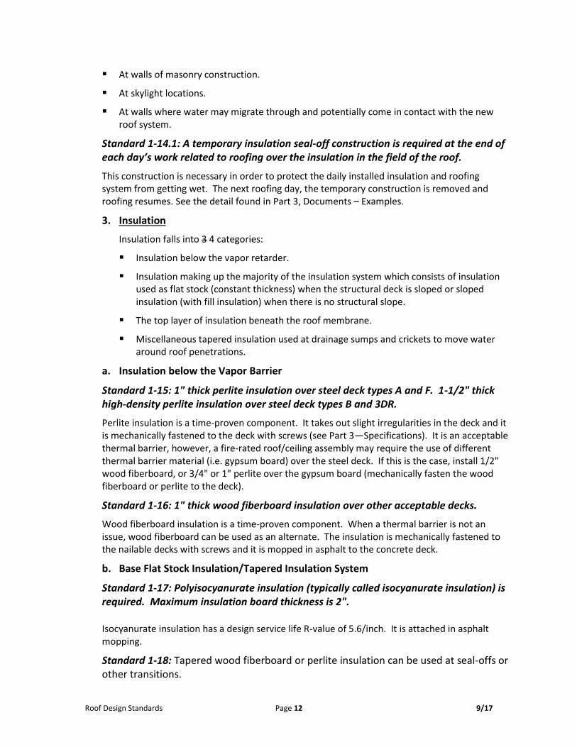
Standard 1-22: Two-ply construction consisting of a type IV base felt and a granular surfaced modified asphalt final felt installed in asphalt mopping. Required at horizontal to vertical transitions. Flashing height information/standards are called out in Part 1B.H and in Part 2, Standards 2-17 and 2-19.
The base flashing extends the waterproofing membrane up a vertical surface to where water impact is no longer a concern. The base flashing is finished-off with sheet metal detailing (underlayment and metal) for long-term performance.

Roof Design Standards Page 14 9/17
5. Concealed Flashing (Underlayment) beneath for Sheet Metal and Sheet Metal Flashing
a. Concealed Flashing for Sheet Metal
Standard 1-23: 45 mil EPDM flashing with adhered seams or W.R. Grace Ice and Water Shield underlayment
Underlayment is used to "finish-off" a detail before the sheet metal can be installed. Since there are joints in the sheet metal once installed, the underlayment protects the detail from moisture that can get behind the sheet metal joints.
Both products are time-tested components. The W.R. Grace product with its self-sticking characteristics can be difficult to work with.
Standard 1-23a: Concealed flashing special termination for water tightness
The same day the concealed flashing is installed at conditions where it can’t be relied on to be watertight at the top of the flashing (such as at wall or wall expansion joints), a termination bar is to be installed and sealed.
b. Sheet Metal Flashing
Standard 1-24: 24-gauge color-coated galvanized steel is the typical sheet metal flashing material.
Sheet metal flashings protect the concealed flashings and ultimately the roof base flashing at roof penetrations. They must be properly held in place to handle wind forces and sloped to shed water.
The galvanized steel is coated in the factory with Kynar 500 paint. Warranted for 20 years, this material has shown no significant problems in the 30+ years it has been used in this area. It is the most economical sheet metal flashing as it requires no painting and is made of galvanized steel.
Other metals capable of 40-year life expectancy, although more expensive than the color coated galvanized steel, include:
Aluminum Copper Stainless Steel
Standard 1-24a: Roof edge metal flashings are to be designed and installed in accordance with ANSI/SPRI ES-1.
This is an International Building Code (IBG) requirement. Contractor formed roof edge metal flashings are required by Minnesota State. (Pre-engineered sheet metal edge flashings are not allowed.) The National Roof Contractor’s Association (NRCA) assists roof design professionals and has tested specific edge metal flashings for the roof design professional to incorporate into the roof documents.
Roof edge details shown in Part 3 depict meeting ANSI-SPRI ES-1.
For more information see: www.NRCA.NBT/RP/Technical/Details/Files/Itsdetails.pdf

Roof Design Standards Page 15 9/17
6. Roof-Related Wood Blocking
Standard 1-25: Non-treated (preservative) wood blocking and plywood.
Wood blockings within the roof system are used to support the roof membrane, membrane base flashings, sheet metal underlayment, and sheet metal flashings. 4x4 wood cants offer the best horizontal-to-vertical roof membrane support. Solid blocking constructions have been accepted by MN Code officials for roof edge constructions, etc. Wood stud wall construction has been rejected in the past. Metal stud wall construction provided all cavity spaces are filled with fiberglass batt insulation. Fire-rated board may be needed (attached to the stud wall) per code requirements. Plywood and other wood blocking can be utilized over the gypsum board.
Non-treated wood products are required to be protected from moisture and have a minimum moisture content allowance of 19% at the time of insulation. This creates a dimensionally stable product.
Preservative treated wood products often times are not protected from the elements and have excessive moisture contents which can result in a very dimensionally unstable product difficult to anchor and at times demonstrating poor performance because of dimensional problems (bowing, twisting, and cupping). Preservative treated wood used as part of the roof system assembly is not acceptable.
When constructing wood curbs with multiple vertical blocking and plywood members, provide staggered joints for all layers and minimum 12" laps.
Standard 1-25a: Fire-treated wood blocking and plywood.
Discussions with code officials have concluded that incidental wood blockings and plywood which are part of the roof system and its flashings (24" high plywood) are not needed to be fire-treated.
C. Drainage
1. Slope/plan configuration
Standard 1-26: Minimum 1/4"/ft. roof slope using tapered insulation, structural slope, or a combination of the two. 3'x3' flat spots, centered at the roof drain are required to accommodate drain detailing. Minimum 1/8th/ft. tapered insulation is allowed in reroofing construction as long as the roof structure is analyzed for ponding instability.
Ponded water reduces the roof service life. The Minnesota State Building Code requires ¼” per foot slope in new construction. This is the final roof slope after camber, deflection, etc. The 3' x 3' flat spot at the roof drain will not affect the roof’s service life due to the extra roofing felt in that area. This 3' x 3' area provides for optimal construction of the roof membrane, lead flashing and extra felt plies.
Sloped insulation (only) is the simplest, least risky to design and construct. Four-sided structural slope is best, however not commonly seen. Structural slope is typically one or two sided and it then needs tapered insulation to assist at eh other two sides. This involves more design and installation work to resolve.
There may be roof plan situations where greater than 1/4 "/ft. is needed, such as near a roof drain to climb at a steeper rate (i.e., 1/2"/ft. or even 1"/ft.) to reach the beginning of the tapered insulation system, or if a roof area is tightly configured (usually 1/2"/ft. will be used).

Roof Design Standards Page 16 9/17
Standard 1-27: Unobstructed drainage is required. Roof penetrations within 6' of the primary drain and within 3' of a valley line are not acceptable. Insulation crickets (saddles) are required at roof penetrations.
Unobstructed drainage is an important element in a 40-year roof vs. say, a 20- or 30-year roof. A roof penetration’s flashing in a valley line can wear out faster due to the concentration (flow) of water on it. The penetration can possibly hold water or allow water entry (not a good spot to have a problem because water is directed right to the problem).
Standard 1-28: A roof drain is required to be located within 10' of a cooling tower.
Water from the cooling tower is generated (condensate, mist, or even maintenance flushing) and a drain nearby will address this extra water source.
Standard 1-28.1: Locate drains at the mid-spans of roof structure, if possible.
Standard 1-28a: In new roof design, locate roof drains no closer than 15’ away from roof edges.
Standard 1-29: Sloped-insulation shall be designed with 45 valley lines from the drain.
The 45 valley, although less than 1/4"/ft. produces the maximum valley line slope. Sloped insulation with 45º valley is the simplest to design and construct.
Standard 1-29a: Complimentary sloping planes (i.e., 1/4"/ft. on all planes of a drainage layout) are required.
Complimentary sloped insulation requires less work to design and construct than non-complementary sloped insulation. Using non-complimentary slopes (i.e., 1/4"/ft. with 1/2"/ft.)
not only creates non-45 valley lines, they create a construction problem. They are not acceptable. Insulation saddles or crickets used for slope-to-drain, create non-45º valley lines and are not acceptable (except at roof penetrations, see Standard 1-27).
2. Drainage types/materials
Standard 1-30: Primary roof drains with overflow drains or overflow scuppers are required. Primary roof drain leaders are to be connected to the interior storm sewer system and not discharged to grade. Overflow roof drains can be per the following order of preference:
a. Interior overflow drain piped to a storm drainage system (separate from primary roof drain)
b. Interior-exterior piping; drain pipe runs through the interior of the building and exits through the exterior wall using a lambs tongue. Maximum 3 feet above grade, with splash block on grade. Protecting the wall between the lambs tongue and the splash block should be addressed. One option would be installing a stainless steel plate.
c. Freefall overflow scuppers. Avoid if possible except where there is a high-low roof condition, such as from a penthouse roof to the main roof.
When overflow drains aren’t doable, a recommended plan layout for overflow scuppers is to locate the overflow scuppers through the roof edge, 8 feet away from the roof drain. This will provide the 2” overflow height requirement (8’ @ ¼” per foot = 2”) and creates a fairly simple plan layout (see Part 3, Roof Plan).

Roof Design Standards Page 17 9/17
Size and locate overflow drains or scuppers to meet code requirements. Documentation that the roof structure can support accumulated water is required.
Standard 1-31: Roof drains (primary and overflow) shall be Josam 21500 or Mifab R1200-JD-STR with an aluminum vandal-proof dome. Primary roof drains require a 3' x 3' lead flashing stripped in with two additional felt plies.
When new roof drains (and leaders) are needed, recommend using 4" diameter roof drains to minimize insulation heights at perimeter details and to minimize susceptibility to freezing, frost closure, or blockings. 3" diameter roof drains or less should be avoided.
The roof drain to roof membrane tie-in is a critical connection in roofing. Of all the drains available, these makes and models provide the best-designed flange component to receive and clamp down on the roofing materials for long-term performance.
3. Non-Acceptable Drainage Items
The following are some of the other common drainage items not acceptable on Minnesota State Standard Roofs and why:
Non cast iron roof drains (PVC roof drains, for example)—Durability and ability to create a well-attached and watertight condition are not equal to the cast iron roof drain.
Adjustable cast iron roof drains or bi-level cast iron roof drains—Performance history shows problems with the sealant-based threaded connection over long periods of time. Also, with bi-level drains, the watertight integrity of the lower clamping ring can be problematic.
Plastic drain screens—Performance history shows they are not as durable, or as vandal proof, as the required metal screen.
Standard 1-32.1 (existing roof replacement only): Evaluate the existing roof drainage system and design the new roof drainage system for compliance with code requirements.
A properly sized roof drainage system is important in removing water from the roof surface. With building additions, changes in the interiors and unique site conditions, the existing drainage system can be less than adequate.
Often, with a reroofing project, roof drain location changes are necessary to obtain unobstructed drainage.
When an existing roof drain is moved or when a roof drain is eliminated, or when other drain modifications are planned (including leader work), the design will need to be submitted to the MN Department of Labor and Industry for approval.
Consult with a mechanical engineer for evaluation, design, and document preparation related to roof drainage of a reroofing project.
Standard 1-32.2 (existing roof replacement only): Remove and replace existing drains (not leaders).
Due to the various edges, conditions, and disruption during reroofing construction, the existing roof drains must be replaced.

Roof Design Standards Page 18 9/17
Standard 1-33: Access to each roof drain from the interior is required.
In order to access the underside of the roof drain during reroofing construction or for future repair work, an access panel or removable architectural feature is required. A lay-in ceiling is acceptable.
D. Roof-Related Items
1. Roof penetrations
Standard 1-34: Minimize the number of roof penetrations. Items like security lights, antennas, weather stations, or any other piece of equipment must be mounted to a wall, not the top of the parapet or on the roof.
Penetrations breech the monolithic roof membrane and then need to be flashed-in to reestablish water tightness. They often require servicing, which involves work and traffic at/within the penetration/area. The fewer of these opportunities for problems, the more likely the roof will perform.
Exceptions: One roof penetration, properly detailed to allow conduit and/or piping lines to connect
to a mechanical unit, so long as the lines are supported by the unit or the supporting framework, is allowed within a few feet of the mechanical unit.
Occasionally lightning protection may be required, contact a Minnesota State Roof Consultant and a lightning protection company.
2. Mechanical Equipment Support
Standard 1-35: If installing new equipment on the roof, such as solar panels, cooling towers, air handling units, etc., provide a sleeper curb structure on circular support posts with a minimum clearance of 36” from the roof membrane to bottom of structure, to allow for roof maintenance and future roof replacement.
3. No conduits or piping on roof
Standard 1-36: No conduits and/or piping runs that require support on the roof membrane or penetration through the roof. No lights with conduit can penetrate the roof. No conduits buried within the insulation of the roof system.
Similar to the previous standard, these often times need more through-roof or bearing-onto roof supports. Often times expansion and contraction of these lines cause supports to move and cause problems with the roof membranes.
4. Roof Access
Standard 1-37: Roof access is required to all roof areas.
Some examples of roof access types include a roof hatch (with interior stair to hatch), a door from an adjacent building area or mechanical penthouse, or an exterior wall or roof-mounted ladder between roof elevations.
Exterior Ladder Guidelines:
Designed by a structural engineer, OSHA approved. Wall mount desired, only to masonry back-up wall with a masonry surface. Anchors cannot
penetrate any through-wall flashing. Expansion conditions may cause exception to above. Roof mount is more common and often more viable.

Roof Design Standards Page 19 9/17
A platform, which is required over the roof edge, is typically roof mounted.
5. Misc. Roof Items
Standard 1-38: Misc. Roof Items
1. Pitch pans are not acceptable.
Pitch pans are not acceptable as they require frequent maintenance.
2. Skylights
A skylight, although penetrating the roof, would be considered a separate element of the roofing system. Skylights are typically do not provide 40-year of life, although they can be detailed in such a way that the roof performance will not be compromised. (See Part 3B, Details).
A skylight’s daylighting attributes need to be weighed against the extra cost in detailing (as to not affect the roof performance) and their track record of condensation and /or water entry problems. If they are to be part of the building they will be identified as not part of the 40-year roof.
Skylight design/construction is improving and if/when a 40-year skylight is ready to be incorporated, it will have a standard.
Suggestion: If a skylight is chosen, consult with the Minnesota State Window Consultant for acceptable types and detailing.
3. Penthouses
Mechanical penthouses on roofs are discouraged, however, if they are designed, their construction is to conform to codes and the current Minnesota State Facilities Design Standards. Minnesota State will accept a CMU knee wall with a minimum height of five block courses, metal stud wall construction and a sheet metal exterior pane. Construction must meet code requirement for fire resistance.
If a sheet metal exterior panel design is approved, contact Minnesota State Roof Design Consultant for panel options.
4. Guardrails
If required by code, permanently wall mounted guardrails are the preferred approach.
5. Roof Hatches
For new construction, shall be located a minimum of 15 feet from roof edge and shall have fall protection guardrails.
6. Solar Panels
Roof loading and layout for servicing and roof access/maintenance are two key aspects to address. Paver ballasted arrays are not allowed.
Any structure/platform to have a minimum clearance of 36” from the roof membrane to bottom of structure, to allow for roof maintenance and future roof replacement. Circular support posts are required and no cross-bracing allowed within 16” of the top of the roof membrane.
Associated equipment, cabling, conduit required to meet these Standards and Minnesota State Facilities Design Standards and Minnesota State Exterior Masonry Design Standards.

Roof Design Standards Page 20 9/17
E. Walls Adjacent to Roofs (existing buildings)
Masonry walls:
a. Masonry walls adjacent to roof areas may or may not be constructed to Minnesota State Design Standards. If evaluation indicates the need for through-wall flashing, see Standard 1-29, current edition of the Minnesota State Design Standards & Minnesota State Exterior Masonry Design Standards.
b. As an option, masonry walls approximately 6' tall or shorter can be covered with custom formed or pre-engineered sheet metal over plywood underlayment, if aesthetically acceptable to the campus. Bottom of the sheet metal wall material is to be 16" minimum above roof membrane. This will allow proper base flashing access.
Precast concrete panel walls:
a. Typically this wall type does not have/incorporate through-wall flashing. It typically contains vertical joints and a surface-mounted sheet metal flashing or possibly a shallow cut reglet with a sheet metal reglet flashing.
b. The preference is to cover the wall as described above, followed by repairing the deteriorated vertical sealant joints and cutting a shallow reglet (if existing is non-existent or too low for proper flashing).
c. If the wall cannot be covered, the preferred approached would be to cut-in a shallow reglet. The insulation system is to be protected according to Standard 1-6.
Sheet metal walls:
a. If the wall is watertight/has an underlayment, it is fine to stay as is as long as it has an adequate flashing height and base flashing access.
b. If the wall is watertight/has an underlayment, however, does not have adequate flashing height or base flashing access, it may need to be cut off to the desired height, supported, and re-secure.
c. If the wall is not watertight, it is to be replaced or possibly covered over with sheet metal. Contact a Minnesota State roof consultant for design standards.
Note: Walls being covered with sheet metal over underlayment over new plywood may require the plywood to be fire-treated. See latest code requirements.
Standard 1-39: Masonry walls with cavity construction require through-wall flashing (per current edition of the Minnesota State Facilities Design Standards & Minnesota State Exterior Masonry Design Standards). Through-wall flashing heights shall comply with Standard 2-18 (RR1).
Standard 1-40: Wall penetrations are to occur above the through-wall flashing.
Moisture entering a masonry wall cavity or wall penetration can eventually enter a roof and cause it to leak and fail if the wall is not properly flashed or the flashing is penetrated.

Roof Design Standards Page 21 9/17
Standard 1-41: Masonry walls are to have a cut-in reglet with a sheet metal insert (see detail example in Part 3).
Walls covered by sheet metal and underlayment:
Standard 1-42: See Standards 1-23 and 1-24 for roof related materials. (see B. above)
A pre-engineered sheet metal standing seam or custom formed vertical flat seam wall covering option can be used to save cost if the sheet metal is aesthetically acceptable. No exposed fasteners or sealant is allowed. No snap seam pre-engineered panels are allowed.
F. Walkways
Standard 1-43: No walkway materials (i.e., wood, rubberized pads, concrete pavers) are acceptable.
These materials can be expected to shorten roof performance primarily due to their effect on the roof membrane. Pavers and wood can become embedded into the membrane over time. Rubberized pads, which are adhesive or asphalt attached, can trap moisture resulting in blisters and membrane failure.
The gravel surfaced built-up roof is durable enough for normal foot traffic and maintenance. See Standard 1-21 for requirement at concentrated foot traffic locations.
G. Roof Configuration
Standard 1-44: Control joints in the roof membrane are required when roof dimensions exceed 150', when roof configuration creates small areas adjacent to large areas (narrow to wide) and when decks change type (and no expansion is expected). (See Part 3, Documents—Examples).
H. Miscellaneous Guidelines
a. Flashing Heights
In new construction, windows, doors, and louver sills, along with through-wall flashing, adjacent to the roof must be designed at elevations to allow for ample roof flashing. In reroofing construction, if inadequate roof flashing height exists, raising window, door, and louver sills or redoing through-wall flashing can be challenging and costly to accomplish, however, must be done, unless a variance is given by Minnesota State.
It is important to achieve roof-flashing heights that will not only accommodate initial roofing, but will accommodate future reroofing applications as well.
It is necessary to gather accurate as-built heights above the existing roof deck to these items and look for design options that will allow them to remain as long as they are functioning properly.
Standards for existing flashing heights (and heights above deck) for these items, along with flashing height standards if they need modifying, are discussed in Standards 2-17 through 2-19.
b. Base Flashing Access
Sheet metal counter flashing must be designed and be installed to be removable to access all the way to the top of the base flashing.

Roof Design Standards Page 22 9/17
c. Lightning Protection Roof Penetrations
Down-leaders are to be installed perpendicular to the base flashing, 8” above the roof surface. The cabling is not allowed in the parapet or wall assembly.

Roof Design Standards 23 9/17
Part 2
Documents Preparation/Submission and Approval
Roofing Design Standards
3rd Edition

Roof Design Standards 24 9/17
Part 2: Documents Preparation/Submission and Approval A. Drawings and Specification Standards
For CADD and specification requirements, see the current Minnesota State Facility Design Standards.
See Part 3 for graphic representations of some of the standards along with roof plans, details, and specification section examples.
1. Roof Plan Standards
Standard 2-1: Minimum roof plan scale of 1/16"=1'-0".
This scale is typically large enough to allow for clear understanding of drainage, detailing, and special notations. Some areas of small size (square footage) and complicated drainage design and/or detailing may require an enlarged roof plan.
Standard 2-2: Roof plan calls out the slope rate is; how the roof is sloped (deck, insulation, or both) with notation reference points of insulation system thickness, minimums (at roof drains) and other thicknesses, and uses different graphic slope indicator symbols for structural slope vs. sloped insulation.
Clearly and accurately describing the drainage on the roof plan is very important so there are no assumptions of how positive slope-to-drain will be accomplished with the unique features each building’s roof has.
Standard 2-3: Develop and apply standard notations and symbols that are consistent and easy to follow and are referenced on the roof plan.
Standard notations and symbols provide clear, accurate, and consistent information about features on the roof plan that a roofing contractor needs to know. If abbreviations are used, then they require a short definition.
Standard 2-4: All mechanical penetrations are shown on the plan.
Accurately placing all mechanical penetrations onto the roof plan with their proper size from other drawings (such as mechanical) is key to knowing if any are too close to a roof drain, a valley line, or even to close to a wall (to allow proper membrane/flashing construction).
Mechanical penetrations include, but are not limited to: vent stacks, heat stacks, intake/exhaust units, pipe penetrations, roof hatches, cooling towers, roof drains, overflow drains, etc.
Standard 2-5: Control joints, expansion joints, and wall expansion joints are required to be shown and resolved completely to their intersection with other penetrations.
These are key design (structural/movement) elements and if not placed accurately on the plan can lead to assumptions of roof construction and a high risk of roof failure.
Standard 2-6: All details are referenced on the roof plan using detail balloons or keynotes.

Roof Design Standards 25 9/17
2. Detail Standards
Standard 2-7: 3"=1'0" scale on all details.
This scale provides the clarity of material types and thickness and other design intentions so they are easy to understand for bidding and installation.
Standard 2-8: Insulation system notations (materials and thicknesses) are required on one detail per sheet of details (minimum) and for each type of deck on the building.
To not call out the insulation system once on a sheet or per deck requires the reader to assume things about the insulation system and that will lead to problems in bidding and construction. To call this information out on all details is unnecessary and can even lead to mistakes such as inconsistent notation variations (more quality control procedures).
Insulation systems need to be clear for the bidder and installer since these systems determine
the major costs in the roofing project.
Standard 2-9: When a detail is used for a “similar” detail condition, clear and thorough “similar to” notation is required. If that information can’t be understood a 3"=1'0" detail is warranted.
Without any explanation, or when the “similar to” information is too complicated, the bidder and installer are assuming again and that can lead to problems.
Standard 2-10: Gravel stop roof edge design is not permitted.
Standard 2-10.1: Canted roof edges are not permitted.
The gravel stop sheet metal is physically bonded to the roof membrane and splitting of the membrane can and does occur over time due to their different coefficients of expansion.
Standard 2-11: Wood blocking with positive slope (1"/foot minimum) is required at the tops of roof expansion and wall expansion and wall expansion joints in lieu of no blocking or other expansion joint devices (i.e., rubber bellows).
The wood will support the sheet metal and underlayment and will allow expansion to occur. The rubber bellows-type expansion joint is not acceptable as an expansion joint.
Standard 2-12: Wood blocking curbs are preferred over metal curbs at roof penetrations.
When metal curbs are connected to the roof membrane, their different coefficients of expansion can cause splits or tears to occur over time. Stripped-in metal curbs are not allowed.
If a metal curb exists, and its flange is not stripped in, wood such as plywood can be applied to the curb face, provided it can be done in such a way as to allow the existing mechanical unit to be reset and be resecure.
Standard 2-13: Wood blocking curbs of roof expansion, wall expansion, and control joints are required to extend full height to wall or roof edge intersections.
This construction allows the detail and its useful purpose to reach the roof perimeter successfully. Stopping short and introducing sheet metal extensions, or tapering down to meet the roof edge height will cause performance problems.
Standard 2-14: Sheet metal cap flashing cover plate design:
Up to 8" wide cap flashing conditions:

Roof Design Standards 26 9/17
Maximum 10' spans of cap flashing, joined with 6" wide cover plates and screwed with a screw through neoprene washer at center of cover plate.
Greater than 8" wide cap flashing conditions: Maximum 10' spans of cap flashing joined with “s-cleat” cover plates nailed at one side. For cap flashing design, see Standard 1-16.1.
Standard 2-15: Drive-cleat joinery is required at cap flashing corners.
Standard 2-16: No sealant allowed except at reglet insert locations (sealant priming required). Weldable sheet metal hoods required at penetrations which cannot be capped with sheet metal or don’t have mechanical unit hoods.
Sealant needs monitoring and maintenance and maintenance work needs to be minimized. The reglet insert (at a masonry wall) is best for roof base flashing termination, yet it needs sealant to make it completely watertight. It will need maintenance. Sheet metal joints are backed-up with underlayment, therefore, need no sealant and subsequent maintenance.
At heat stack locations where welding is not an option, liquid solder material is acceptable. Verify with the stack manufacturer to make sure the warranty will remain intact.
Standard 2-17: Base-flashing heights shall be a minimum of 12" (top of membrane to top of base flashing). Exceptions: Roof edge and roof hatch base flashing height can be 8" minimum.
Design intent doesn't necessarily mean installation reality. 12" goes beyond the minimum 8" (industry) standard because of those unforeseen installation shortcomings and to protect better against climatic effects. If 12" is achievable, then that height is expected.
Less height is allowed at roof edges because the entire edge is wrapped watertight.
Standard 2-18: (RR1) Lowest through-wall flashing membrane to be no less than 30” above existing deck.
When the existing through-wall flashing elevation does not meet, the through-wall flashing will need to be raised. Through-wall design and construction are per Minnesota State Masonry Design Standards.
The lowest through-wall flashing membrane is to be a minimum of 8” above the highest intersecting roof edge or expansion/control joint, however no less than 30" above the roof deck.
Through-wall flashing, per Minnesota State Exterior Masonry Design Standards, is expected to last as long as the masonry wall which is about twice as long as the roof. Installing it at this height above the roof provides for proper flashing heights in the future should roof replacement involve additional insulation.
Standard 2-19: If door, window, or louver sills will not create at least a 12" base flashing height with the reroofing system design, they will need to be raised.
Window or louver sills to be no less than 30” above the roof deck. Door sills to be no less than 24” above the roof deck.
Often times the door, window, or louver can be reduced in height in order to raise the sill elevation, yet not impact the existing head. This approach is preferred as long as campus personnel are ok with the change and the louver size reduction is approved by a mechanical engineer.
Raising an existing door will likely require stair or platform modifications to meet code.

Roof Design Standards 27 9/17
3. Specification Standards
Standard 2-20: Roof related wood blocking and roof drains are typically identified in specification sections other than Section 07 51 00. It is important to not have treated wood blocking for roofing construction.
Standard 2-21: A description of work paragraph is required in Section 011000 or can be put in 07 51 00, Part 1.
This describes the roof system in a summary form by general component descriptions. It also allows certain construction installation conditions to be summarized for bidding and installation coordination.
Include a brief description of the existing construction. The following paragraph is an example of language to be used regarding existing construction:
Existing construction may not be as shown on the drawings and some modification of details may be required to accomplish the intent of the documents. The details shown and the information provided have been taken from the original drawings for the building, but are not represented, or guaranteed, by the Owner and Architect/Engineer as being accurate as to the actual as-built and present conditions. Verify conditions at the site and perform all work to complete the project under this contract, regardless of variations that may be found, without additional cost to the Owner. All modifications or adjustments are to be approved in advance by the Architect/Engineer.
Standard 2-22: Work Schedule information is required in Section 00 73 80 and in Section 01 10 00 when full-time observation and testing services will be used.
This information discusses the roof construction schedule and liquidated damages, should the work go beyond an established number of roof working days. A formula is used to determine the number of roof working days and it is as follows:
# of squares of roof/30 squares/week = # of weeks + 2 weeks = Total number of weeks
Total number of weeks /3.5 days/week = Number of Roof Working Days
The squares/week amount can vary depending on roof size, access, complexity, roofing contractor factors, and weather. Consult with a Minnesota State Roof Design Consultant for further information. The roof working days are typically related to roof construction only (not mechanical, structural, masonry, etc.).
The roof working day is defined in Section 00 73 80, along with who determines it, and the amount of fee to cover a full-time observer per roof working day.
Standard 2-23: Liquidated damages in the amount of $X/roof working day are required in Section 00 73 80.
The cost (X) is determined by the party that will be providing the full-time observation. Please consult with Minnesota State.
Standard 2-24: The words “and/or”, “or equal” are not acceptable.
Directly taken from the current Minnesota State Facilities Design Standards. The goal is to only specify known high quality products. A/E is responsible to ensure all products specified meet the minimum performance requirements of the Minnesota State Design Standards.

Roof Design Standards 28 9/17
Standard 2-25: A 5-year contractor warranty is required for the work related to each specification section.
Accepted by contractors in this State, this warranty covers the entire system, labor and materials, during the key period in a built-up roof life.
Roofs require maintenance and warranties don’t cover those needs. Manufacturer’s warranties are made to protect the manufacturer so the cost for such is better spent on maintaining a roof.
B. Construction Cost Estimating
There are many variable to consider when cost estimating a roof. These include such things as overall size, number of areas, number and height of roof levels, access (from grade, roof to roof) and the ratio of roof area to roof flashings, time of year construction takes place, roofing contractor base and availability to name a few. The Minnesota State Standard Roof that this manual describes typically costs about one and one-half to twice double the cost of an industry standard roof. This extra cost relates to proactively addressing quality construction/long term performance, such as unobstructed slope-to-drain, well attached system components, and protection from adjacent moisture sources (i.e. walls, penetrations, parapets). Insulation component costs are higher because of the increased R-value and the use of stable, time-proven materials. Correcting existing deficiencies to accommodate long-term performance design and future reroofing is also an initial cost element. Minnesota State’s Roof Consultant will assist with and comment on construction cost estimating during review of the design phase submissions.
C. Design Phase Reviews
1. Schematic Design (SD) Phase
See attached SD checklist/review process
Formal review by a Minnesota State Roof Design Consultant is required before proceeding to DD phase.
6. Design Development (DD) Phase
See attached DD checklist/review process
Formal review by a Minnesota State Roof Design Consultant is required before proceeding to CD phase.
7. Construction Documents (CD) Phase
See attached CD checklist/review process
Formal review by a Minnesota State Roof Design Consultant is required before proceeding to Bid phase.
8. Bidding Document (BD) Phase
See attached CD checklist/review process
Notes:
1. For objectives of these phase submissions pertaining to the entire building, see current Minnesota State Facilities Design Standards.
2. If Minnesota State requires any phase to be resubmitted, the roofing portion of the resubmitted phase will be reviewed by the Minnesota State Roof Design Consultant.

Roof Design Standards 29 9/17
3. Architect is to submit entire set of phase documents to Minnesota State’s Roof Design Consultant.
D. Phase Checklist Forms (See the following pages)
1. Schematic Design Phase – Submission Requirements Checklist
2. Design Development (DD) Phase - Submission Requirements Checklist
3. Construction Documents (CD) Phase - Submission Requirements Checklist
4. Bidding Documents (BD) Phase – Submission Requirements Checklist

Roof Design Standards 30 9/17
Schematic Design (DD) Phase Submission Requirements Checklist
Written Requirements
_____ Brief roof system description
_____ Provide Probable Roof Construction Cost.
_____ Verify there are no rooftop heating and cooling units. No mechanical or electrical piping
on roof.
Drawing Requirements (minimum 11” x 17”)
Roof Plan
_____ Indicate all adjacent roof areas (new or existing) including type of roof and elevation
_____ Indicate if overall drainage scheme will be structural slope or sloped insulation.
_____ Identify probable building expansion joints on roof.
Elevation (or section)
_____ Show walls that are above roofs with:
_____ Doors, windows, louvers.
_____ Probable wall construction type.
Review Process
Architect’s SD To Minnesota State To Architect
Roof Design Consultant copy to Minnesota State/others for final review 7 calendar days maximum

Roof Design Standards 31 9/17
Design Development (DD) Phase Submission Requirements Checklist
Written Requirements _____ Address the SD review comments from Minnesota State Design Review Consultant. _____ Note any substantial changes from SD. _____ Provide energy calculations for the roof/ceiling assembly (one per each insulation system). _____ Provide outline specification sections 075100 and 076200. _____ Updated Probable Roof Construction Cost.
Drawing Requirements (24” x 36” minimum) Roof Plan _____ Scale 1/16”/1 ft. minimum. _____ Drainage layout showing slope rate(s), type of slope (tapered insulation or sloped deck). _____ Show primary and overflow drainage. _____ Show mechanical unit locations (no heating/cooling units). _____ Indicate locations of expansion and control joints. _____ Show roof access. Elevation/Building Sections/Wall Sections _____ Show sills of all louvers, doors and/or windows. _____ Indicate wall construction type. _____ how through-wall-flashing conditions (if applicable). Details (3” = 1’-0”) _____ Roof Edge(s) _____ Control Joint(s) _____ Wall(s) _____ Roof Drains _____ Wall Expansion Joint _____ Key penetrations _____ Mechanical curbs _____ Do details and wall/building sections match construction-wise? _____ Are detail balloons referenced on the wall/building sections? _____ Any wall or building sections need a detail?
Review/Approval Process Architect’s CD To Minnesota State To Architect Roof Design Consultant copy to Minnesota State/others for final review 14 calendar days maximum

Roof Design Standards 32 9/17
Construction Documents (CD) Phase Submission Requirements Checklist
Written Requirements
_____ Address the DD review comments from Minnesota State Design Review Consultant.
_____ Note any substantial changes from DD. _____ Complete specification sections 075100 and 076200
_____ 075100 Summary of work. _____ 075100 Roof working days. _____ 075100 Roof related wood blocking and roof drains
_____ Updated Probable Roof Construction Cost.
Drawing Requirements
_____ Complete roof plan with key plan and sign-off block (without signatures).
_____ Complete details. _____ Details correctly drawn and ballooned on wall sections, elevations, etc.
Drawings and Specification Information Correlation
_____ Roof system (existing and new) – 01 10 00.
_____ Materials and installation – technical sections.
Review/Approval Process
Architect’s CD To Minnesota State To Architect
Roof Design Consultant copy to Minnesota State/others for final review 14 calendar days maximum

Roof Design Standards 33 9/17
Bidding Documents (BD) Phase Submission Requirements Checklist
Written and Drawing Requirements
_____ Address the CD review comments from the Minnesota State Roof Design Consultant.
_____ Note any substantial changes from CD.
Status (have documents been sent?)
_____ State Plan Review.
_____ MN Dept. of Labor and Industry, Plumbing and Engineering Unit
Review/Approval Process
Architect’s Bid Documents To Minnesota State To Architect
Roof Design Consultant copy to Minnesota State/others for final review 7 calendar days maximum

Part 3
Document – Examples
Roof Plan Drainage Highlights
Roofing Design Standards
3rd Edition
The details, graphics and related information shown in the following examples is intended to illustrate the intent of the Minnesota State Roofing Design Standards. The information contained herein is not intended for actual construction and is subject to revision based on changes and/or refinements in local, state and national building codes. The actual design and configuration of these and similar details will vary based on design parameters, existing conditions, and other factors unique to each project. The designer is responsible for the final roof design conforming to the intent of these standards and any variance must be submitted by written request to the Minnesota State Facilities Design and Construction Department.

Part 3: Documents—Examples
A. Roof Plan Drainage Highlights
Portions of roof plans have been created to show how the Design Standards relate to roof plan
design and eventually document preparation. The standards are referenced with this symbol: Also some comments are provided.
B. Details
1. Common Detail Types
The 3"=1'0" scale details are the more common ones found on Minnesota State Standard Roof construction documents. They are not the only acceptable details.
Details RE-1 is fully noted and drawn graphically correct as examples of clear understandable details.
Design Standard reference numbers have been placed on certain details to provide a graphic connection to the appropriate standard. Comments are also shown on the details. Standard references and comments would not be put on actual details.
2. Typical Sheet Metal Details
Following the common detail types are acceptable details that could be used as is or modified to meet project specifics. Again, some of the Design Standards have been place for graphic connection.
Detailing at intersecting roof features is important to accomplish, in order to convey intent of a solution. Enclosed are some of the key intersecting details, often solved by sheet metal.
C. Specifications Sections
Example Specification Sections are included at the end of Part 3, they contain actual specification information that incorporates the Roof Design Standards that may not be incorporated if the project was developed prior to the Third Edition Roof Design Standards. The examples are from a specific project and may not be appropriate for any other project. Each roof project will require eliminating items that don’t relate to the project and adding items that do relate. New items that are added will be reviewed by Minnesota State’s roof consultant for acceptance/incorporation. The Minnesota State front end information is to be obtained from Minnesota State. Changes/updates may occur from time to time, consult Minnesota State for their latest requirements.


Part 3
Document – Examples
DETAILS
Roofing Design Standards
3rd Edition
The details, graphics and related information shown in the following examples is intended to illustrate the intent of the Minnesota State Roofing Design Standards. The information contained herein is not intended for actual construction and is subject to revision based on changes and/or refinements in local, state and national building codes. The actual design and configuration of these and similar details will vary based on design parameters, existing conditions, and other factors unique to each project. The designer is responsible for the final roof design conforming to the intent of these standards and any variance must be submitted by written request to the Minnesota State Facilities Design and Construction Department.


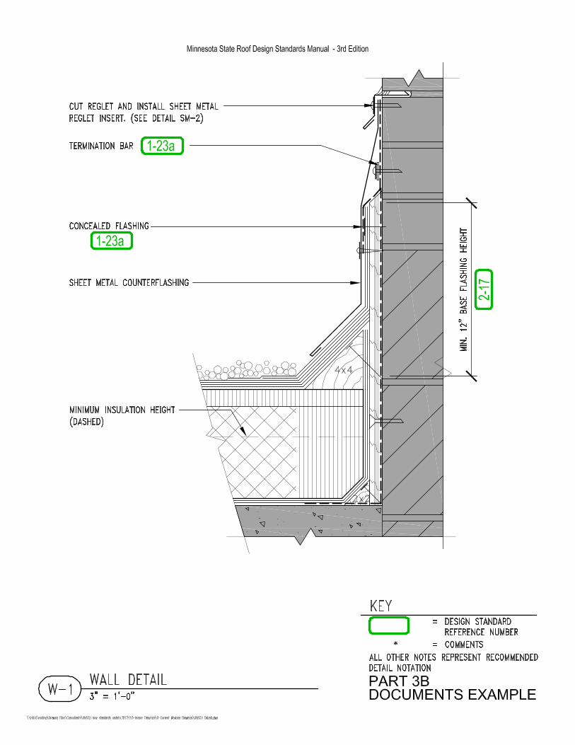


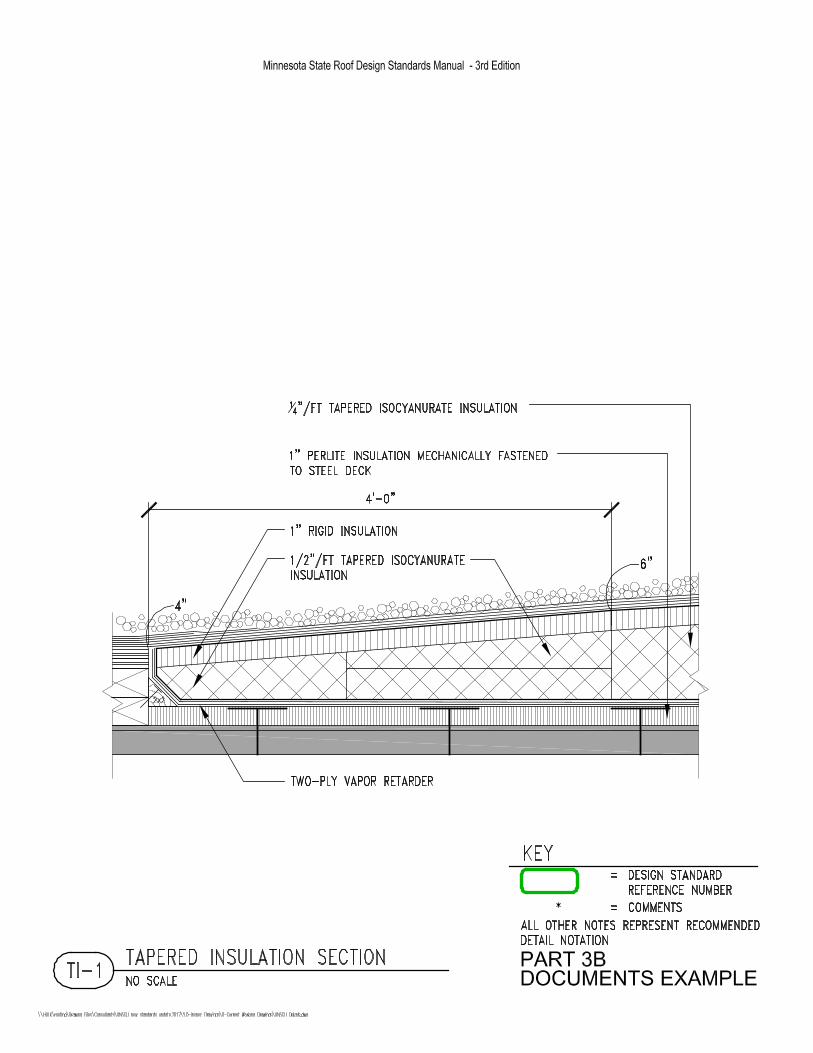


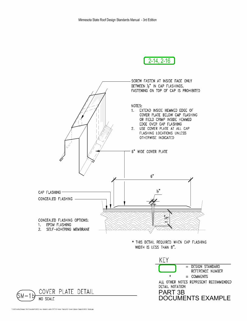


Part 3
Document – Examples
SAMPLE SPECIFICATIONS
Roofing Design Standards
3rd Edition
The specifications and related information shown in the following examples are intended to illustrate the intent of the Minnesota State Roofing Design Standards. The information contained herein is not necessarily intended to be used for a particular project, but will need to be edited to work with a specific project based on the uniqueness of that project. The designer is responsible to ensure compatibility of all materials used on the project. The actual design and configuration of the roof will vary based on design parameters, existing conditions, and other factors unique to each project. The designer is responsible for the final roof design conforming to the intent of these standards and any variance must be submitted by written request to the Minnesota State Facilities Design and Construction Department.

June 2017
Specification Examples
New Roofing
Sections
06 10 05 Roof-Related Rough Carpentry 07 51 00 Built-Up Bituminous Roofing 07 62 05 Roof-Related Sheet Metal Flashing

Example
ROOF-RELATED ROUGH CARPENTRY 06 10 05 - 1 June 2017
SECTION 06 10 05
ROOF-RELATED ROUGH CARPENTRY
PART 1 - GENERAL
1.1 SUMMARY
A. Section Includes: 1. Roof-related wood blocking 2. Sheet metal angle
B. Related Sections: 1. Section 07 51 00 - Built-Up Bituminous Roofing 2. Section 07 62 05 - Roof-Related Sheet Metal Flashings
1.2 QUALITY ASSURANCE
A. Use adequate numbers of skilled workers who are thoroughly trained and experienced in the necessary crafts and who are completely familiar with the specified requirements and the methods needed for proper performance of the Work of this Section.
B. Codes and Standards: In addition to complying with the pertinent codes and regulations of governmental agencies having jurisdiction, unless otherwise specifically directed or permitted by the Architect/Engineer, comply with the following: 1. Product Use Manual of the Western Wood Products Association for selection
and use of products included in that manual. 2. Plywood Specification and Grade Guide of the APA-The Engineered Wood
Association.
1.3 DELIVERY, STORAGE, AND HANDLING
A. Deliver materials to the site, insofar as practicable, in manufacturer's original containers and bearing the trademarks and names thereof. Grademark stamped on all standard yard dimension lumber or certified for compliance. Plywood grade stamped.
B. Carefully stack lumber and plywood to prevent warping. Keep dry.
1.4 PROJECT CONDITIONS
A. Existing Conditions: Examine the areas and conditions under which work of this Section will be installed. Correct conditions detrimental to the proper and timely completion of the Work. Do not proceed until given conditions have been corrected.
B. Environmental Requirements: Wind velocity and temperature limitations shall be based on Contractor's ability to apply materials in the specified manner.
C. Protection: Provide appropriate protection on roof-related traffic, staging, and storage areas. As a minimum, protection shall consist of 45-mil EPDM, 1" extruded polystyrene insulation, and 3/4" plywood ballasted with sandbags. Remove protection materials upon completion of the work.

Example
ROOF-RELATED ROUGH CARPENTRY 06 10 05 - 2 June 2017
PART 2 - PRODUCTS
2.1 LUMBER
A. Non-preservative treated, standard light framing grade, sound and thoroughly seasoned with less than 19 percent moisture content at the time of installation and at time roofing is installed. 1. Douglas Fir 2. Eastern Pine 3. No. 3 Southern Pine 4. No. 2 Western Hemlock 5. Spruce-Pine-Fir
2.2 PLYWOOD
A. C-D Exposure 1 or better, APA Rated Sheathing, non-preservative treated, meeting U.S. Products Standard PS1 or Performance Standard PRP-108 for Soft Wood Plywood Construction and Industrial, with less than 19 percent moisture content at time of installation and at the time roofing is installed.
2.3 FASTENERS
A. Stainless steel fasteners required for fastening into existing treated wood.
B. Lag screws: Zinc or cadmium plated, 3/8" diameter with 1-1/2" penetration into blocking.
C. Lumber to lumber: Cement coated or annular thread nails with minimum 1-1/4" penetration into adjoining member.
D. Plywood to lumber: 1. Nails: Ring shank or annular thread nails with minimum 1-1/4" penetration
into adjoining member. 2. Screws: Minimum #14 flat head countersunk wood screws, zinc or cadmium
plated steel or stainless steel, with minimum 1-1/4" penetration.
E. Lumber or plywood to concrete or masonry: Tapcon or Gripcon anchors, minimum 1/4" diameter with 1" penetration, minimum 300 lb. per anchor installed withdrawal resistance. Other corrosion resistant drilled-in type masonry anchors may be used if equivalent in pull-out strength.
F. Lumber or plywood to steel deck: Minimum #14 sheet metal screw, zinc or cadmium plated; through 5/8" diameter steel washers for lumber.
G. Sheet metal angle to lumber: Minimum #14 flat head wood screws, zinc or cadmium plated steel or stainless steel, with minimum 1-1/4" penetration.
H. Sheet metal angle to steel deck: Self-drilling screw fastener, size 12 - 24 by 7/8, HWH Teks/4 manufactured by ITW Buildex
2.4 MISCELLANEOUS
A. Sheet metal angle: 12-gauge galvanized iron, size as shown on the Drawings.

Example
ROOF-RELATED ROUGH CARPENTRY 06 10 05 - 3 June 2017
PART 3 - EXECUTION
3.1 PREPARATION
A. Grout, shim, patch, or fill existing construction as necessary to properly install wood members.
B. Perimeter wood blocking installation shall, as a minimum, be in accordance with recommendations of Factory Mutual Loss Prevention Data Sheet 1-49, September 2009.
3.2 WOOD BLOCKING
A. Install in straight lines, level planes, and at proper elevation.
B. Top surface of horizontal blocking is to match the surface elevation of the new roof insulation.
C. Do not use warped wood members unless they can be fastened adequately to permanently hold them in their required alignment.
D. When constructing wood curbs with multiple vertical blocking and plywood members, provide staggered joints for all layers and minimum 12" laps.
E. Lumber or Plywood to Lumber: 1. Maximum spacing of 12" on-center, staggered across face of piece and
located within 3" of each end of piece. Maximum spacing of 6" on-center, 8' each way from outside corners for roof edge blocking.
2. Heads shall be flush with wood surface and nail shall penetrate adjoining piece minimum 1-1/4 inch.
3. Minimum 100 lb. per nail installed withdrawal resistance.
F. Lumber or Plywood to Concrete or Masonry: 1. Spacing as shown on Drawings or maximum 3' on-center when not specified,
staggered. Maximum 18" on-center, 8' each way from outside corners for roof edge blocking.
2. Countersink head flush with surface but no more than 1/3 the thickness of the fastened piece.
3. Minimum 300 lb. per anchor withdrawal resistance or number of fasteners increased accordingly from that specified, minimum penetration of 1 inch.
G. Lumber or Plywood to Steel Deck: 1. Verify the presence of conduit below the steel deck prior to installation. 2. Spacing as shown on the Drawings or maximum 18" on-center for screws
when not specified, and staggered if lumber is more than 5" wide. Maximum 9" on-center, 8' each way from outside corners for roof edge blocking.
3. Countersink head flush with surface but not more than 1/3 the thickness of the fastened piece.
4. Minimum 150 lb. per anchor withdrawal resistance or number of fasteners increased accordingly from that specified, minimum penetration of 1-1/2 inches.

Example
ROOF-RELATED ROUGH CARPENTRY 06 10 05 - 4 June 2017
3.3 FIELD QUALITY CONTROL
A. Construction Observation: The Owner may retain the services of an independent agency for testing and construction observation. Notify Owner's construction observer whenever work is to be done in sufficient time to arrange observation and testing. The Contractor shall not commence Work until the Owner's construction observer is present.
B. Alignment and elevation of installed wood shall be checked by Contractor and may be checked by Architect/Engineer.
C. Withdrawal tests of installed fasteners may be required if attachment is in question.
3.4 CLEANING
A. Keep the premises in a neat, safe, and orderly condition, free from an accumulation of sawdust, cut ends, and debris at all times during execution of this Work.
END OF SECTION 06 10 05
Example
BUILT-UP BITUMINOUS ROOFING 07 51 00 - 1 June 2017
SECTION 07 51 00
BUILT-UP BITUMINOUS ROOFING
PART 1 - GENERAL
1.1 SUMMARY
A. Section Includes: 1. Thermal barrier 2. Vapor retarder 3. Insulation 4. Bituminous membrane roofing 5. Lead flashing for drains
B. Products Installed But Not Furnished Under This Section: 1. Caps, sleeves, and umbrella hoods
C. Related Sections: 1. Section 06 10 05 - Roof-Related Rough Carpentry 2. Section 07 62 05 - Roof-Related Sheet Metal Flashing
D. Summary of Roofing-Related Work - The Work includes, but is not limited to: 1. Use of a fume elimination system is required. Set up and operate in
accordance with manufacturer's recommendations. 2. Install new non-treated roof-related wood blocking as indicated at the details. 3. Areas A1 and A3 - Mechanically fasten 1" rigid insulation through 5/8"
thermal barrier to the steel deck, followed by a two-ply fiberglass felt vapor retarder in asphalt moppings, 1/4"/ft. tapered isocyanurate insulation in asphalt, and a top layer of 1" rigid insulation in asphalt.
4. Area A2 – Install 1" rigid insulation mopped in asphalt followed by a two-ply asphalt vapor retarder, tapered isocyanurate insulation backfill to level off deck camber, ¼"/ft. tapered isocyanurate insulation in asphalt, and a top layer of 1" rigid insulation in asphalt.
5. Install four plies of fiberglass felts in asphalt moppings with an asphalt flood coat and gravel surfacing. Install a two-ply base flashing system at all canted and vertical surfaces.
6. Install color-coated galvanized iron sheet metal flashings at the details. 7. Install new roof drains to be provided by plumbing contractor and tie-in above
deck by roofing contractor. Coordinate work with mechanical and plumbing contractors.
8. Provide and install new wood mechanical curbs. Install one new roof hatch (to be provided by others).
9. Provide membrane protection 12' wide adjacent to work areas. 10. General Contractor shall protect the building and its contents on a daily basis,
and provide and maintain temporary protection systems. An airtight and watertight condition must be provided on a daily basis. General Contractor shall provide protection against wind, moisture, vermin, etc. from entering the interior of the building. Suitable provision for drainage shall be included, no trapping or holding of water is allowed.

Example
BUILT-UP BITUMINOUS ROOFING 07 51 00 - 2 June 2017
1.2 SUBMITTALS
A. Product Data: 1. Thermal barrier 2. Vapor retarder and membrane felts 3. Insulation, each type 4. Base flashing, each type 5. Bituminous materials, each type
a. Asphalt manufacturer shall identify softening point, minimum flashpoint, minimum finished blowing temperature, and equiviscous temperature (EVT) for each asphalt shipment.
6. Fasteners: Insulation fastener only 7. Miscellaneous:
a. Concealed flashing, each type b. Uncured flashing, each type
B. Shop Drawings: Tapered insulation system
C. Samples: 1. Bitumen, one quart 2. Aggregate (25 lbs.) 3. Aggregate weight tickets for each shipment to the site.
D. Warranty: Signed warranty forms (Close-out submittal).
E. Contractor's Qualifications: Roofing Contractor shall be prepared to submit the following within five (5) days of Owner's request: 1. Detailed anticipated construction schedule and staffing plan. 2. AIA Document A305, Contractor's Qualification Statement. Including written
evidence of a satisfactory experience record with work of this type and scope; and, if requested by the Owner, can provide five references for projects of a size exceeding 75 percent of the area included in this Project that are at least five years old. These references shall include project schedules, including bid date, start and completion dates, Owner and/or Engineer contacts including names, addresses and telephone numbers, and the specific components existing and installed on each referenced project.
F. Written schedule of Contractor's plan to meet allotted working days specified herein.
1.3 QUALITY ASSURANCE
A. Provide thermostatic controls and visual thermometer on bitumen kettle, maintain in working order, and keep calibrated.
1.4 DELIVERY, STORAGE, AND HANDLING
A. Provide continuous protection of materials against wetting and moisture absorption.
1.5 PROJECT CONDITIONS
A. Examine the areas and conditions under which work of this Section will be installed. Correct conditions detrimental to the proper and timely completion of the Work. Do not proceed until given conditions have been corrected.
Example
BUILT-UP BITUMINOUS ROOFING 07 51 00 - 3 June 2017
1. Existing construction may not be as shown on the Drawings and some modification of details may be required to accomplish the intent of the Documents. The details shown and the information provided have been taken from the original drawings for the building, but are not represented, or guaranteed, by the Owner and Architect/Engineer as being accurate as to the actual as-built and present conditions.
2. Verify dimensions and construction conditions at the site and perform all work to complete the Project under this Contract, regardless of variations that may be found, without additional cost to the Owner.
3. All modifications or adjustments, are to be approved in advance by the Architect/Engineer.
B. Environmental Requirements: 1. Wind velocity and temperature limitations shall be based on Contractor's
ability to apply materials in the specified manner. 2. No work permitted when ambient temperature is below 0 F, or wind chill
factor is below -20 F. 3. Special precautions are required when ambient temperature is below 40 F.
C. Protection: 1. Provide protective material and methods as required to protect existing
building and adjacent surfaces, features, and property. 2. Contractor is responsible for water damage to existing insulation and building
interior that may result from damage to existing materials, and for subsequent water damage due to inadequate repair work.
3. Traffic on no-reroofing areas shall be kept to a minimum. Provide adequate protection of the roof membrane if traffic on such roof areas is necessary.
4. Provide appropriate protection in roof-related traffic, staging, and storage areas. As a minimum, the protection shall consist of 45-mil EPDM, 1" extruded polystyrene insulation, and 3/4" plywood ballasted with sandbags. Remove protection materials upon completion of the Work.
5. Install temporary insulation seal-offs at completion of each day's work and completely remove upon resumption of work.
6. Install materials in manner that will prevent bitumen drippage. 7. Place used asphalt mops in water and remove from the roof at the end of
each day's work. Dispose of or store away from combustible materials. 8. Coordinate application of membrane to protect underlying materials from
wetting or other damage by the elements on a continuous basis. 9. Completely install sheet metal sleeves, caps, or enclosures on a daily basis.
1.6 WARRANTY
A. Roofing Subcontractor's Warranty: Prior to acceptance of the Work, furnish written five (5) year warranty covering all roofing work specified herein, using the form at the end of this Section.
1.7 WORK SCHEDULE AND LIQUIDATED DAMAGES
A. Roof-Related Pre-Construction Conference (applies to work associated with roof-related Specification Sections 061005, 075100, and 076205): 1. Prior to starting any work on the Contract, the Architect, Owner, Owner's
representative, Owner's roofing observer, the General Contractor and the

Example
BUILT-UP BITUMINOUS ROOFING 07 51 00 - 4 June 2017
roofing subcontractor shall meet at the site to discuss procedures, schedules, review submittals, etc. for the Work. The roofing contractor's manpower scheduler and foreman, who will be on the Project full-time directing the Work, and the roofing contractor's sheet metal foreman and other subcontractors' foremen, must attend this meeting. If the roofing contractor's foremen are not present at this scheduled meeting, the meeting will be canceled and rescheduled at roofing contractor's expense.
B. Schedule: 1. Crew size: Roof work shall be conducted by crews of no less than six (6)
workers. 2. Sequencing:
a. Roof-related work shall be constructed in segments of not less than one (1) full roof working day and a minimum of 40 hours per week. Contractors shall staff crew accordingly to accomplish roof-related work within the number of roof working days intended. General Contractor and roofing-related subcontractors shall coordinate and provide a written schedule on how they intend to meet working days allotted (see Submittals).
b. Work shall be conducted between the hours of 7:00 a.m. to 5:00 p.m. Monday through Friday of each week. Work on other than those hours or days specified, including legal holidays, school holidays, Saturdays and Sundays may be granted provided a request is made at least 48 hours in advance and that Contractor assumes all responsibility for safeguard of Owner's property
3. Completion: Contractor shall complete all roof work within 44 roof working days. This applies to all roof-related work included in this Section and Sections 061005 and 076205.
C. Notification: At least 14 calendar days before beginning work covered by this Section (and associated roof-related Sections included herein) and a minimum of two business days prior to subsequent work, the roofing contractor shall inform the Architect/Engineer in writing of when work will be performed.
D. Definition: For the purpose of this Contract, a “roof working day” is defined as any date that roofing work is done or can be done on the Project as determined by the roofing construction observer. Nonworking days could result if bad weather arises. Documentation will be made by the Owner's roofing consultant each day on a daily field report as to whether the day is to be considered a roof working day or a non-roof working day.
E. Liquidated Damages: In accordance with the provisions as set forth in Article 8 of the General Conditions, the Contractor shall pay to the Owner as fixed, agreed, and liquidated damages for each roof working day of delay beyond the time of completion until the Work is completed or accepted, the sum of One Thousand No/100 Dollars ($1,000.00) per roof working day and the Contractor and his sureties shall be liable for the amount thereof. Liquidated damages will be enforced by a deduct supplemental agreement to the Contract.

Example
BUILT-UP BITUMINOUS ROOFING 07 51 00 - 5 June 2017
PART 2 - PRODUCTS
2.1 THERMAL BARRIER
A. Non-structural glass mat faced, non-combustible, water-resistant treated gypsum core panel for use in commercial roof assemblies. Thickness shall be 5/8" thick, as shown on the Drawings. 1. Georgia-Pacific DensDeck Prime 2. USG Securock 3. Membrane manufacturer-approved equal with capability to receive hot asphalt
moppings.
2.2 VAPOR RETARDER AND MEMBRANE FELTS
A. Fiberglass felt: 1. CertainTeed Flintglas Ply Sheet Type IV 2. Firestone Ply IV 3. GAF Gafglas Ply 4 4. Johns Manville GlasPly IV 5. Tamko Tam Ply IV
2.3 INSULATION
A. Isocyanurate: Closed-cell polyisocyanurate foam core with fiberglass facers both sides, meeting ASTM C1289, Type II, Class 1, Grade 2 (20 psi), dimensional stability of 2%, 24 hr minimum cure time plus an additional 24 hours per inch, and a maximum board thickness of 2 inches. Maximum 4' by 4' boards.. All packages shall have RIC/TIMA label. Approved manufacturers are: 1. Atlas 2. CertainTeed 3. Firestone 4. GAF 5. Johns Manville 6. Hunter Panels
B. Rigid: Only perlite will be acceptable for contact with steel decks or within 2'-0" of heat stacks 1. Perlite: ASTM C728, U.L. and F.M. rated and labeled, with TopLoc coating,
maximum 4' by 4' boards. a. Johns Manville Fesco b. GAF EnergyGuard
2. Wood fiberboard: ASTM C208, with surface treatment, maximum 4' by 4' boards, manufactured by: a. Firestone b. Huebert Fiberboard c. International Fibreboard d. International Bildrite
C. Tapered isocyanurate: Factory-fabricated isocyanurate insulation as described above, with slope as shown on the Drawings. Direction changes shall use mitered boards. Minimum 1" rigid insulation shall cover isocyanurate boards.

Example
BUILT-UP BITUMINOUS ROOFING 07 51 00 - 6 June 2017
D. Tapered edge strip: Rigid wood fiberboard or perlite insulation with maximum 1/2 in./ft. slope, 1-1/2 in./ft. slope approved for use at seal-offs.
E. Batt: ASTM C665, Type I, preformed glass fiber batt
F. Extruded polystyrene: ASTM C578, Type IV, minimum 1.6 pcf density.
1. DiversiFoam CertiFoam
2. Dow Styrofoam
3. Owens Corning Foamular
G. Polyethylene foam: Ethafoam M1 A/S, 2.3 psf closed-cell polyethylene foam manufactured by Dow Chemical Company.
H. Spray-applied polyurethane foam: Froth-Pak two-component polyurethane spray foam system, 1.75 pcf, manufactured by Dow Chemical Company, phone 800-800-FOAM.
2.4 BASE FLASHING
A. Asphalt-saturated organic felt: ASTM D226, Type I, No. 15
B. Exposed sheet: Granule surfaced, asphalt mopped modified bitumen, black granules 1. CertainTeed Flintlastic GMS Premium 2. Firestone SBS Premium 3. GAF Ruberoid Mop Plus 4. Johns Manville Dynalastic 250 or DynaFlex 5. Tamko Awaplan Premium
2.5 BITUMINOUS MATERIALS
A. Asphalt primer: ASTM D41
B. Asphalt: ASTM D312, Type III
C. Plastic Cement: 1. Premium grade, asphalt base, asbestos-free, ASTM D4586. The following
products are approved. No substitutions permitted. a. CertainTeed FlintPatch b. GAF LeakBuster Matrix 202 SBS Flashing Cement c. Karnak 19 AF d. Johns Manville Bestile Utility Cement e. Tremco ELS
2. Non-premium grade, asphalt base, asbestos-free, ASTM D4586, Type I may be used only at seal-offs and temporary conditions.
2.6 FASTENERS
A. Thermal Barrier/Insulation to Steel Deck: 1. Self-tapping #12 or #14 fluorocarbon coated screw with drill point, through
minimum 6.5 sq. in. hot-dipped galvanized steel plate. Plates and screws must be clearly labeled from the same manufacturer and shall be intended to be used together.
2. Install screws with manufacturer's recommended screw guns and bit sizes.

Example
BUILT-UP BITUMINOUS ROOFING 07 51 00 - 7 June 2017
3. Minimum pull-out strength of 300 lb. per fastener. 4. Minimum 3/4", maximum 1-1/4" penetration through flanges. Length to
penetrate top of deck but not to extend below the bottom of the rib. Change screw length in tapered insulation sections to meet this criteria.
5. Approved manufacturers are: a. CertainTeed b. Firestone c. Johns Manville d. OMG e. SFS Intec f. Tru-Fast
B. Base flashing system: Galvanized 1-1/4" barbed roofing nails through 1" metal discs into wood members; 1" length into vertical plywood blocking.
C. Scupper flanges to wood blocking: 1-3/4" galvanized roofing nails
D. Lag screws: Zinc or cadmium plated, 3/8" diameter with 1-1/2" penetration into blocking.
2.7 MISCELLANEOUS
A. Reinforcing fabric: ASTM D1668, Type I
B. Concealed flashing: 1. Cold-applied self-adhering membrane: Ice and Water Shield manufactured by
Grace Construction Products. 2. Cured EPDM field sheet, 45 mil thick; manufactured by Carlisle, Firestone, or
Johns Manville. 3. Uncured EPDM: 60 mil thick; manufactured by Carlisle, Firestone, or Johns
Manville. 4. Adhesive: As recommended by flashing manufacturer.
C. Uncured flashing: 1. Uncured EPDM: 60 mil thick; Sure-Seal Uncured Elastoform Flashing
manufactured by Carlisle or Johns Manville. 2. Uncured neoprene: 60 mil; Neoprene FormFlash manufactured by Firestone. 3. Adhesive: As recommended by flashing manufacturer.
D. Aggregate: ASTM D1863
E. Lead flashing: Fed. Spec. QQ-L-201F and Amendment 2, Grade B, 4 lb/sq.ft., 36" by 36" sheets.
F. Membrane protection: 1. 45-mil EPDM membrane 2. 1" extruded polystyrene insulation 3. 3/4" plywood 4. Sandbag ballast

Example
BUILT-UP BITUMINOUS ROOFING 07 51 00 - 8 June 2017
PART 3 - EXECUTION
3.1 PREPARATION
A. Prior to mopping insulation or felts to new concrete deck, coordinate with Architect/Engineer for testing a section of the deck for dryness (i.e. no foaming of asphalt). When deck is sufficiently dry, as determined by Architect/Engineer, prime the concrete surface at the rate of 1 gal/100 sq.ft. and allow to dry.
B. Surfaces shall be free of all dirt, debris, loose materials, and free moisture in any form. Mechanically scrape exposed surface if necessary to remove projections.
C. Reset or replace existing fasteners for materials exposed but left in place that are loose, deformed, damaged, or corroded.
D. At all wall details and vertical transitions, and/or where indicated on the Drawings, prior to installation of wood blocking and vapor retarder, fully adhere one ply of uncured flashing to deck and wall. Lap onto deck a minimum of 6", and extend a minimum of 3" past height of new wood blocking, as shown on the Drawings. Fully cement minimum 3" laps.
E. Perimeter wood blocking installation shall, as a minimum, be in accordance with recommendations of Factory Mutual Loss Prevention Data Sheet 1-49, Perimeter Flashing
3.2 THERMAL BARRIER
A. Stagger panel end joint with respect to each other and all joints. Butt panel ends and edges.
B. Temporarily hold in place until first layer of insulation is installed over the thermal barrier and mechanically fastened to the deck.
3.3 VAPOR RETARDER
A. Install two plies of fiberglass felt in a continuous shingle sequence in asphalt moppings in a manner to prevent asphalt drippage. Glaze coat of installed felt plies required if subsequent roof system construction cannot be installed the same day, or as approved by Architect/Engineer. Phased vapor retarder construction (one ply plus one ply) will not be permitted.
B. If the vapor retarder is installed as a temporary membrane (i.e. not covered with insulation/membrane, herein indicated as the final roof system), special requirements will apply, including, but not limited to the following: 1. The specified uncured flashing at wall to deck conditions and all wood
blocking (curbs, penetrations, parapets, etc.) shall be installed and covered with fully-adhered EPDM with sealed laps. Extend the two-ply vapor retarder a minimum of 16" up walls. The EPDM concealed flashing on the inside of perimeter walls shall overlap the two-ply vapor retarder a minimum of 3" and shall be securely fastened to prevent wind uplift. Install a glaze coat of asphalt over the two-ply vapor retarder.
2. Set roof drains at the elevation of the temporary membrane so drainage can be provided. At the time the final roof system is installed, the drains shall be reset to the correct higher elevation as shown on the Drawings.
3. The temporary membrane must be protected until the final roof system can be installed. Areas of material storage, high traffic volume, or concentrated work areas (mechanical, etc.) shall be protected with 1" insulation and 3/4" plywood ballasted with sandbags.

Example
BUILT-UP BITUMINOUS ROOFING 07 51 00 - 9 June 2017
4. Contractor shall pay for an infrared scan of the temporary membrane if the final roof system is not installed within four weeks of the temporary membrane. The infrared scan will be completed prior to the installation of the final roof system (figure $1,500 for up to 200 squares, $2,500 for greater than 200 squares).
5. Contractor shall pay the roofing observation and testing firm directly for providing the infrared scan services.
6. Contractor shall pay for fees for roofing observation if the roof working days are extended as a result (figure $1,000/day).
C. Maximum moisture content of felts at the time of application shall be one percent of dry weight.
D. Squeegee or press felts into hot bitumen providing tight, smooth laminations without wrinkles, buckles, kinks, or fishmouths. Air void pockets as determined by test samples, shall not exceed 5% per interply mopping for individual sample and average of all samples shall be less than 3% per interply mopping.
E. Carry all plies up to the top of the wood cant, or as shown on the Drawings.
3.4 INSULATION
A. Mechanically fasten first layer of new insulation through the thermal barrier to steel deck using one fastener for every two sq.ft. in a pattern recommended by Factory Mutual. Use two fasteners minimum for partial boards. Verify the presence of conduit below the deck prior to fastener installation. Install screws with manufacturer's recommended screw guns and bit sizes with minimum 3/4", maximum 1-1/4" penetration below flange. Screws penetrating the rib shall be removed and a new screw installed.
B. Use full moppings of asphalt for application of each subsequent insulation layer.
C. Maximum moisture content of insulation at time of application shall be 4% of dry weight.
D. Place each insulation board while bitumen still tacky. Lay with edges in moderate contact but do not force into place.
E. Stagger joints of upper layer with joints of bottom layer and stagger short joints in each layer. Stagger joints a minimum of 25% of the board dimension. Fill insulation joint wider than 1/4" with insulation cut to fit.
F. Step-down or roll-down all insulation layers so that full embedment and a flat surface is obtained.
G. Extra care shall be required to properly cut and fit insulation boards to conform to changes in deck slope and other irregularities.
H. Install tapered insulation with primed side up or between layers of insulation as shown on Drawings. If tapered isocyanurate insulation is used, provide minimum 1" rigid insulation over isocyanurate.
I. Provide tapered edge strip and batt insulation at locations shown on the Drawings.
J. Top surface of insulation shall be smooth and continuous with the primed surface exposed to receive the new membrane.

Example
BUILT-UP BITUMINOUS ROOFING 07 51 00 - 10 June 2017
3.5 MEMBRANE ROOFING
A. Installation of felt plies shall be in a continuous shingle sequence, such that there are no laps against the flow of water, after installation of insulation. Glaze coat of installed felt plies required if flood coat and gravel surfacing cannot be installed the same day, or as approved by the Architect/Engineer. Phased membrane construction will not be allowed.
B. Maximum moisture content of felts at time of application shall be one percent of dry weight.
C. Provide full, uniform moppings of asphalt for membrane construction so that felt shall not touch felt.
D. Squeegee or press felts into hot bitumen providing tight, smooth laminations without wrinkles, buckles, kinks, or fishmouths. Air void pockets, as determined by test samples, shall not exceed 5% per interply mopping for individual sample and average of all samples shall be less than 3% per interply mopping.
E. Carry felts to the top of the cant strip and cut off evenly.
F. Install two additional plies of fiberglass felt in full mopping of asphalt at sleeper curbs, pipe supports, and splashpans.
G. Install one additional felt ply under the membrane at access doors, ladders, hatches, etc.
H. Install one additional ply of fiberglass or organic felt in full mopping of asphalt in valleys of drain sumps.
I. Minimize traffic on recently installed membrane. Use sequencing and equipment that will prevent asphalt displacement.
J. The use of felt laying machines is prohibited.
K. Application of hot asphalt on any surface that causes foaming of the asphalt shall be cause for rejection of the roof area.
L. Prime both sides of metal flanges for flashing sleeves, set in a trowel coat of plastic cement, and strip in with two plies of fiberglass felts and hot bitumen moppings feathered onto flange and onto membrane.
M. Extend all vent stacks as necessary to maintain a minimum height of 12" above the completed membrane.
3.6 COMPOSITION BASE FLASHING SYSTEM
A. Install where roofing system joins vertical or canted surfaces on a daily basis or as approved by the Architect/Engineer.
B. Prime bare masonry surfaces to receive flashing.
C. Install felt in full mopping of asphalt, pressing in the felt to obtain full contact with bitumen.
D. Install base flashing membrane in a full mopping of asphalt with a minimum temperature of 400 F at application, by mopping surface to receive the membrane and back-mopping the membrane. Fully embed membrane into mopping so as not to create voids. Do not stretch membrane. Seal 4" end laps with plastic cement and reinforcing fabric.

Example
BUILT-UP BITUMINOUS ROOFING 07 51 00 - 11 June 2017
E. Fasten top edge of base flashing at 8" on-center for wood and 12" on-center for masonry.
F. At wall details where indicated on Drawings, seal top of wood blocking by fully adhering one ply of uncured neoprene to neoprene sheet adhered to wall, lapping a minimum of 3", and extending down and lapping over top of base flashing.
G. Install concealed flashing sheets, as indicated, at locations shown on the Drawings immediately after the base flashing is completed. For EPDM, fully cement minimum 3" laps with adhesive and fully adhered EPDM to substrate. For self-adhering membrane, pull the release paper under the membrane and continue to peel it from the membrane. Press the membrane in place and roll seams firmly with hand roller. Laps shall be a minimum of 3 inches.
3.7 FLOOD COAT AND AGGREGATE SURFACING
A. Ensure that all roof surfaces are clean, dry, and free of loose gravel.
B. Pour flood coat uniformly over roof surface prior to installation of exposed sheet metal flashings.
C. Apply aggregate uniformly into hot bitumen with complete coverage, 400 lbs./100 sq. ft.
D. Double flood and gravel in a 10' by 10' area at exterior corners; below splashpans, pipe supports, and access ladders; and within 3' of roof hatches. Remove loose non-embedded aggregate, pour a uniform additional flood coat, and completely cover with aggregate, as described above.
3.8 BITUMEN
A. Maximum temperature in heating equipment: 1. Do not heat asphalt to the minimum flashpoint. 2. Do not exceed the minimum finished blowing temperature for more than a
total of four hours for any batch or portion thereof. 3. Remove from Project asphalt heated above these limits.
B. Temperatures at time and point of application: 1. Asphalt shall be within 25 F of its equiviscous temperature when applied in
the roof system. 2. Bitumen not meeting this criterion shall be reheated or allowed to cool as
required. 3. Do not heat to the minimum flashpoint. 4. Do not exceed the minimum finished blowing temperature for more than a
total of four hours for any batch or portion thereof. 5. Remove from Project bitumen heated above these limits.
C. Rate of bitumen application: 1. Insulation: 30 lbs./100 sq. ft. 2. Asphalt interply moppings: 27 lbs./100 sq. ft. with tolerance of plus and
minus 15 percent. 3. Glaze coat: 10 lbs./100 sq. ft. 4. Asphalt flood coat: 60 lbs./100 sq. ft.

Example
BUILT-UP BITUMINOUS ROOFING 07 51 00 - 12 June 2017
3.9 ROOF DRAINAGE
A. Roofing Contractor shall install roof drain bowl. Mechanical Contractor shall supply and install complete roof drain assembly, connect drain leader to drain bowl, and insulate drain bowl and leader below deck.
B. Extend membrane and lead flashing into the drain bowl, and clamp.
C. Prime lead flashing for drains. Set in trowel coat of plastic cement and strip in with two plies of fiberglass felt and hot bitumen moppings.
D. Complete and coordinate flashing of the drains with construction so that roof drainage is fully functional at the end of each day's work.
E. Water shall not pond at any roof drain location for more than one hour. Contractor shall perform watertesting at all roof drain locations. If ponding water remains after one hour, correction shall be the Contractor's responsibility.
F. Temporarily protect drains. Sections of insulation board may be cut to fit into drain base to keep debris from falling into drain leaders. Remove temporary protection prior to precipitation.
3.10 FIELD QUALITY CONTROL
A. Construction Observation: The Owner will retain the services of an independent agency for full-time construction observation and testing of the Work included in this Section. Notify Owner's construction observer in sufficient time (minimum two business days) to arrange observation and testing whenever work is to be done. The Contractor shall not commence Work until the Owner's construction observer is present.
B. Testing Services Criteria: 1. The Owner, Architect/Engineer, and/or Owner’s Representative reserve the
right to have tests made when deemed necessary. 2. Tests not specified as part of a trade section will be paid for by the Owner
unless such tests reveal a failure of the Work to meet requirements of the Contract Documents.
3. Tests revealing a failure in the Work shall be paid for by the Contractor. 4. Tests shall be made in accordance with recognized standards by a competent,
independent testing laboratory selected by the Owner, Architect/Engineer, and/or the Owner’s Representative.
5. Materials found defective or not in conformance with the Contract Documents shall be promptly replaced or repaired at the expense of the Contractor.
6. Samples required for testing shall be furnished by the Contractor and selected as directed by the Architect/Engineer and/or Owner's representative.
7. The Contractor shall repair openings required for testing to the satisfaction of the Construction Observer.
C. Testing: 1. Bitumen:
a. Samples of bitumen may be taken and tested for conformance to the specifications by the Architect/Engineer for each shipment delivered to the Project.
b. Bitumen temperatures may be periodically checked at the discretion of the Architect/Engineer in the kettle and/or on the roof.

Example
BUILT-UP BITUMINOUS ROOFING 07 51 00 - 13 June 2017
2. Membrane Samples: a. At the discretion of the Architect/Engineer, 4" x 36" test cuts taken
perpendicular to the long dimension of felts may be required, a minimum one for each 5,000 sq.ft.
b. Samples will be examined for quality of construction and compliance with roofing specifications based on an evaluation of entrapped moisture, felt on felt, quantity of air voids, and presence of harmful foreign materials. This evaluation will be based on the delamination of the felt plies (the Jennings Method for built-up membrane analysis).
c. Remove test samples before application of the surface coating at locations selected by Architect/Engineer.
d. Take additional samples as directed by Architect/Engineer when deficiencies are found.
e. Repair of Built-Up Membrane Test Cut: (1) Immediately rebuild test area with cut felts of same type as roof
system, set in plastic cement. (2) Cover repaired area with four layers of felts. Solid mop each layer
into place in hot bitumen. Overlap cut area 3" on all sides with first layer. Lap each succeeding layer 3" on all sides over layer below.
3. Aggregate: Samples may be required if delivered material is in question. 4. Other Tests:
a. Isocyanurate insulation will be observed, and may be tested, for conformance with ASTM D303 and C550 criteria.
b. Field tests may be performed to evaluate moisture content of installed materials.
c. Withdrawal tests of installed fasteners may be required if attachment is in question.
d. Application of roof system will be checked by Contractor and may be checked by Architect/Engineer.
e. Contractor shall pay roofing observation and testing firm directly for providing an infrared scan following substantial completion, but prior to final completion (figure $1,500 for up to 200 squares, $2,500 for more than 200 squares).
3.11 CLEANING
A. Remove bitumen from surfaces not specified to receive bituminous materials; such as walls, walkways, metal flashing, etc.
B. Repair staining or damage caused by solvent or oil spills.
C. Finished gravel surface roof is to completely cover flood coat and have uniform appearance.
END OF SECTION

Example
BUILT-UP BITUMINOUS ROOFING 07 51 00 - 14 June 2017
BUILT-UP BITUMINOUS ROOFING WARRANTY Owner:
Street Address:
City State Zip
Project Name: Project No.
Project Address:
Date of Final Acceptance:
Roofing Installation Subcontractor:
Street Address:
City State Zip
Phone No. ( )
Fax No. ( )
Email: This warranty stipulates that the above-named Roofing Subcontractor shall, during a period of five (5) years from the date of Substantial Completion of the Work, maintain the roof membrane and flashing systems in a watertight condition and repair all defects which result from faulty workmanship or defective materials, without further cost to the Owner, including replacement of any wet insulation caused by such defects. Excluded from this warranty may be any and all damage to said roof, the buildings or their contents caused by acts or omissions of the Owner; fire, lightning, winds of peak gust speeds of 72 mph or higher, hailstorm, or other unusual phenomenon of the elements; movement or failure of the supporting building structure that causes membrane or flashing failure; or vapor condensation beneath the roof. Exclude from this warranty any damages to the building or the contents. Before expiration of the above warranty period, the above-named Subcontractor shall inspect the roof in the presence of the Owner and make necessary correction of all deficiencies not considered normal. The warranty shall remain in force until the necessary repair work has been done.
ROOFING INSTALLATION SUBCONTRACTOR
Signature
Printed Name
Title
Date

Example
BUILT-UP BITUMINOUS ROOFING 07 51 00 - 15 June 2017
This page is intentionally left blank
Example
ROOF-RELATED SHEET METAL FLASHING 07 62 05 - 1 June 2017
SECTION 07 62 05
ROOF-RELATED SHEET METAL FLASHING
PART 1 - GENERAL
1.1 SUMMARY
A. Section Includes: 1. Sheet metal flashing 2. Sealant
B. Products Furnished But Not Installed Under This Section: 1. Caps, sleeves, and umbrella hoods
C. Related Sections: 1. Section 06 10 05 - Roof-Related Rough Carpentry 2. Section 07 51 00 - Built-Up Bituminous Roofing
1.2 SUBMITTALS
A. Product Data: 1. Color-coated metal 2. Sealant
B. Shop Drawings: For all sheet metal including typical seaming and sheet metal to sheet metal connections.
C. Test results: If Contractor proposes new cap flashing which deviates from the Project Drawings, proposed substitution must be in accordance with the design intent of the Project and test results must be submitted verifying compliance with IBC 2006 ANSI/SPRI ES-1.
D. Samples: 1. Sheet metal manufacturer's standard color chart. 2. Sealant manufacturer's standard color chart.
E. Warranty: Signed warranty forms (Close-out submittal).
1.3 QUALITY ASSURANCE
A. Perimeter edge metal and parapet cap (coping) for low-slope roofs shall comply with IBC 2006 ANSI/SPRI ES-1.
B. Factory shall have capability to show conformance with National Coil Coater's Association Technical Bulletins for factory color-coated steel.
C. Manufacturer to provide factory applied protection for finished color-coated sheet metal by means of a strippable plastic film.
D. Sheet metal items not specifically noted on the Drawings or in the specification shall be in accordance with recommendations of The Architectural Sheet Metal Manual published by Sheet Metal and Air-Conditioning Contractors National Association, Inc. (SMACNA).

Example
ROOF-RELATED SHEET METAL FLASHING 07 62 05 - 2 June 2017
1.4 DELIVERY, STORAGE, AND HANDLING
A. Store flammable materials in conformance with fire codes and in a manner that will not create a potential fire hazard.
B. Exercise care during fabrication and erection to avoid damage to the finished surface.
C. Store color-coated sheet metal in manner that will protect it from exposure to the sun up until the time of installation.
D. Store sheet metal components in a manner that will keep them clean and dry until installed.
1.5 PROJECT CONDITIONS
A. Protection: 1. Prevent damage to new or existing materials, including protection from
damage by ladders and other equipment. Potentially damaging materials such as metal scraps, acid flux, and other debris shall not be permitted to come into contact with the roof surface.
2. Suitable fire extinguishing equipment shall be immediately available at all locations where soldering, welding, or cutting equipment is used.
3. Maintain a fire watch wherever soldering, welding, or cutting is performed.
B. Construction Schedule: Install sheet metal as soon as possible after membrane work has been completed. Sheet metal work shall be fully complete by the given completion date.
1.6 WARRANTY
A. Manufacturer's Warranty: Provide a 20-year written manufacturer's warranty for color-coated sheet metal covering color fade, chalk, and film integrity.
B. Contractor's Warranty: Prior to acceptance of Work, furnish written five (5) year warranty covering all sheet metal flashings specified herein using the form at the end of this Section.
1.7 ROOF RELATED WORK SCHEDULE AND LIQUIDATED DAMAGES
A. Refer to Section 07 51 00 for requirements that also apply to this Section.
PART 2 - PRODUCTS
2.1 SHEET METAL
A. Color-coated steel: Kynar 500 fluoropolymer coating factory applied to 24-gauge galvanized steel, ASTM A653. Touch-up paint for color-coated sheet metal shall be color match as recommended and supplied by the sheet metal manufacturer. 1. Color shall match existing from manufacturer's standard colors. Verify with
Owner at the pre-construction conference. 2. Acceptable materials:
a. ColorKlad by Ryerson b. Pac-Clad by Petersen Aluminum Corporation c. Una-Clad by Firestone Metal Products d. Ultra-Clad by Coated Metals Group e. Carlisle Metal Products

Example
ROOF-RELATED SHEET METAL FLASHING 07 62 05 - 3 June 2017
f. Berridge Manufacturing Company
B. Galvanized steel: ASTM A653, commercial quality, G90 coating designation.
2.2 FASTENERS
A. Fasteners shall be of same material as flashings on which they are used and shall be of type and size as shown on Drawings or specified herein unless noted otherwise. Exposed fasteners through sheet metal shall match new sheet metal color. 1. Zinc or cadmium plated for galvanized steel
B. Fasteners exposed to the weather shall have EPDM washers under heads to ensure watertightness. 1. EPDM bonded washers: Fabco Fastening System Weath-R-Seal Bonded
Washers
C. Sheet metal to wood: 1. Where exposed: No. 8 minimum size steel hex head screw, 1-1/2" long.
Minimum 150 lbs. per screw installed withdrawal resistance. 2. Where not exposed: Minimum #14 flat head wood screw.
D. Sheet metal to sheet metal: Self-tapping screws of 1/2" length and a minimum #3 diameter.
E. Sheet metal to concrete or masonry: Tapcon or Gripcon, specially threaded anchors, 1/4" minimum diameter, length to penetrate masonry minimum 1 inch. Minimum 300 lb. per anchor installed withdrawal resistance.
F. Keeper strips to wood: 1. Nails: Ring shank nail, with minimum 3/16" diameter head, and minimum 1-
1/4" penetration into wood. 2. Screws: No. 8 minimum size steel pan head screw, minimum 3/4"
penetration into wood. Minimum 150 lbs. per screw installed withdrawal resistance.
2.3 SEALANT
A. Polyurethane sealant: ASTM C920, Type M, Grade NS, Class 25, Use M, color selected and approved by Architect 1. MasterSeal NP 2 2. Tremco Dymeric 240FC
B. Primer: Non-staining, quick-drying type and consistency recommended by the sealant manufacturer.
2.4 MISCELLANEOUS
A. Solder: ASTM B32, alloy grade Sn50 (50% tin, 50% lead) or Sn60 (60% tin, 40% lead). Use solder alloy grade which is appropriate for types of flux and heating ranges being used.

Example
ROOF-RELATED SHEET METAL FLASHING 07 62 05 - 4 June 2017
B. Soldering flux: Use least corrosive flux suitable for specific application. Use materials and methods to neutralize as recommended by the flux manufacturer and American Welding Society (AWS). 1. Fed. Spec. 0-F-506C, Type I, Form A or B
C. Pad: 1/8" thick EPDM
PART 3 - EXECUTION
3.1 PREPARATION
A. Verify that surfaces to receive sheet metal are smooth, clean, and have no free water present in any form.
B. Verify that nailers to receive sheet metal are properly placed.
C. Verify shapes and dimension of surface to be covered before fabrication of sheet metal.
D. Cut, clean, and prime reglets to receive new reglet insert flashing.
3.2 FABRICATION AND INSTALLATION
A. Sheet metal installation shall as a minimum, be in accordance with recommendations of Factory Mutual Loss Prevention Data Sheet 1-49, September 2009.
B. Shop fabricate all items requiring soldering or welding unless noted otherwise.
C. Re-coat soldered joints of color-coated sheet metal with material and in manner specified by manufacturer.
D. Sheet metal work shall be of material and gauge specified, and shaped to be installed in strict conformance with details on Drawings.
E. Plane surfaces shall be free from waves or buckles.
F. Turn back exposed metal edges into hemmed edge.
G. Use elastomeric sealant at reglets and scuppers as necessary to make a watertight installation including foam backer rod as necessary to make a good sealant joint.
H. Screw fasteners shall be turned into place rather than driven.
3.3 SOLDERING
A. Clean surfaces to be soldered, removing oils and foreign matter.
B. Pre-tin edges of sheet metal before soldering is begun.
C. Apply flux and begin soldering immediately.
D. Soldering shall be done slowly with well-heated soldering irons until the seams are thoroughly heated and the solder has been completely sweated through the full width of the seams.
E. Remove acid flux residue as recommended by the manufacturer. As a minimum, use a solution of washing soda in water.

Example
ROOF-RELATED SHEET METAL FLASHING 07 62 05 - 5 June 2017
3.4 CAP FLASHING, COUNTERFLASHING, WALL PANELS, AND KEEPER STRIPS
A. Provide preformed cap flashing with drive cleat joinery extending out two to four feet maximum in each direction at corners and intersections of new sheet metal cap flashings.
B. Space cap flashing sections so cover plate locations will be balanced between corners of roof edge.
C. Align cover plates for cap flashing and fascia flashing along roof edges.
D. Lap intersecting counterflashings, except fascia counterflashings, minimum 3", and securely fasten.
E. Sheet metal flashing (not including fascia flashing) exceeding 24" high shall be a vertical flat seam single-lock wall panel consisting of: 1. Panels shall not exceed 16" in width unless noted otherwise. 2. Fabricate and space seams accurately. Flat seams shall be, straight, and
uniform. Bends shall be rounded and not sharp. Seam interlock shall be 3/4". 3. Fasten sides of panels with cleats spaced 12" on-center and locked into panel
seam. Fasten cleats to plywood with two annular thread nails, and to concrete with one flat or pan head masonry anchor. Install fastener 3/4" from end and turn end of cleat to cover fastener head.
4. Fasten top edge of panel with a minimum of two screws through EPDM washers. Locate screws just below drip edge of overlying flashing.
5. Fasten lower edge of panel with a continuous keeper strip.
F. Fasten at center of cover plates along inside face with screws through EPDM washers and field crimp inside edge over cap flashing. Nail fasten S-cleat cover plates at 6" on-center. No fasteners will be allowed in outside face of cover plate.
G. Screw fasten cap flashing on roof edges at 18" on-center. Screw fasten cap flashings (non-roof edge related) and counterflashing to wood blocking with screws through EPDM washers at 30" on-center.
H. For perimeter edge metal with 12" maximum width, fasten outer edge of cap flashing with continuous keeper strip fastened to blocking at 6" on-center. Do not field crimp cap flashing to keeper strip. For perimeter edge metal over 12" in width, fasten outer and inner edge of cap flashing with continuous keeper strip fastened to blocking. Crimp inside face of cap flashing to keeper strip only. When cap/fascia flashing is present, allow additional break in keeper strip to maintain plumb installation of cap/fascia flashing.
I. Fasten counterflashing corners with pop rivets or screws and seal with sealant.
3.5 FIELD QUALITY CONTROL
A. Alignment and elevation of installed sheet metal will be checked by Contractor and may be checked by Architect/Engineer.
B. Withdrawal tests of installed fasteners may be required if attachment is in question.
C. Construction Observation 1. The Owner will retain the services of an independent agency for full-time
construction observation and testing of the work included in this Section. Notify Owner's construction observer whenever work is to be done in
Example
ROOF-RELATED SHEET METAL FLASHING 07 62 05 - 6 June 2017
sufficient time (two days minimum) to arrange observation. The Contractor shall not commence work until the Owner's construction observer is present.
D. Testing Services Criteria: 1. The Owner, Architect/Engineer, and/or Owner's Representative reserve the
right to have tests made when deemed necessary. 2. Tests not specified as part of a trade section will be paid for by the Owner
unless such tests reveal a failure of the Work to meet requirements of the Contract Documents.
3. Tests revealing a failure in the Work shall be paid for by the Contractor. 4. Tests shall be made in accordance with recognized standards by a competent,
independent testing laboratory selected by the Owner, the Architect/Engineer, and/or the Owner's Representative.
5. Materials found defective or not in conformance with the Contract Documents shall be promptly replaced or repaired at the expense of the Contractor.
6. Samples required for testing shall be furnished by the Contractor and selected as directed by the Architect/Engineer and/or Owner's Representative
7. The Contractor shall repair openings required for testing to the satisfaction of the construction observer.
3.6 CLEANING
A. Clean surfaces of flux, scraps, dirt, and other blemishes immediately. Potentially damaging materials shall not contact the roof surface.
B. Remove strippable plastic film from color-coated sheet metal immediately after installation.
END OF SECTION 07 62 05

Example
ROOF-RELATED SHEET METAL FLASHING 07 62 05 - 7 June 2017
ROOF-RELATED SHEET METAL FLASHING WARRANTY Owner:
Street Address:
City State Zip
Project Name: Project No.
Project Address:
Date of Final Acceptance:
Sheet Metal Installation Subcontractor:
Street Address:
City State Zip
Phone No. ( )
Fax No. ( )
Email: This warranty stipulates that the above-named Subcontractor shall, during a period of five (5) years from the date of Substantial Completion of the Work, maintain the sheet metal flashing systems and repair all defects which result from faulty workmanship or defective materials, without further cost to the Owner, including replacement of any wet insulation caused by such defects. Excluded from this warranty may be any and all damage to said roof, the buildings or their contents caused by acts or omissions of the Owner; fire, lightning, winds of peak gust speeds of 72 mph or higher, hailstorm, or other unusual phenomenon of the elements; movement or failure of the supporting building structure that causes flashing failure; or vapor condensation beneath the roof. Exclude from this warranty any damages to the building or the contents. Before expiration of the above warranty period, the above-named Subcontractor shall inspect the sheet metal in the presence of the Owner and make necessary correction of all deficiencies not considered normal. The warranty shall remain in force until necessary repair work has been completed.
SHEET METAL INSTALLATION SUBCONTRACTOR
Signature
Printed Name
Title
Date

Example
ROOF-RELATED SHEET METAL FLASHING 07 62 05 - 8 June 2017
This page is intentionally left blank

June 2017
Specification Examples
Reroofing
Sections
00 73 80 Special Conditions of the Contract
for Construction, Time of Completion, and Liquidated Damages
01 10 00 Summary See New Roofing Examples for Sections 06 10 05 Roof-Related Rough Carpentry 07 51 00 Built-Up Bituminous Roofing
(minus the Summary of Work) 07 62 05 Roof-Related Sheet Metal Flashing

SECTION 00 73 80 Example
MINNESOTA STATE COLLEGES AND UNIVERSITIES
Rev. 11/01/06 00 73 80-1
SPECIAL CONDITIONS OF THE CONTRACT FOR CONSTRUCTION TIME OF COMPLETION AND LIQUIDATED DAMAGES
A. In the event that Substantial Completion of the Work has not occurred on or before July 24, 2015,
then commencing on July 25, 2015, and continuing for each day or fraction thereof until Substantial Completion of the Work is established, the Contractor shall pay to the Owner, at the sole option of the Owner, the amount of One Thousand and No/100 Dollars ($1,000) per diem (“Damage Amount”).
B. The Contractor and the Owner agree that in the event the Substantial Completion of the Work does
not occur on or prior to July 24, 2015, the Owner will suffer damages in an amount which may, due to the special nature of the Project, the Owner’s business and the Owner’s reliance upon the Substantial Completion date, be impractical or extremely difficult to ascertain. The Owner and the Contractor agree that the Damage Amount is a reasonable estimate of the damages that the Owner will suffer in the event that Substantial Completion of the Work does not occur on or prior to the Substantial Completion Date.
C. Payment of liquidated damages shall be in the form of a Change Order reducing the Contractor’s
Contract Sum by the amount of the liquidated damages. If the Contractor refuses to sign the Change Order for liquidated damages, the Owner reserves the right to unilaterally reduce the Contract Sum by the amount of the liquidated damages. If the amount of the liquidated damages exceeds the remaining unpaid balance of the Contract, the Contract Sum shall be reduced by the amount of the unpaid balance and the Contractor shall pay the Owner the difference between the liquidated damages and the unpaid balance.
END OF SECTION

Example
01 10 00 - 1 June 2017
SECTION 01 10 00 SUMMARY
PART 1 - GENERAL
1.1 GENERAL
A. Supply all labor, transportation, materials, apparatus and tools necessary for the entire proper completion of this Work; install, maintain and remove all equipment for the proper execution of this Contract; be responsible for the safe, proper and lawful performance of equipment, maintenance and use of the same; and perform in the best manner, and everything properly incidental thereto, as stated in the Contract Documents or reasonably implied therein.
1.2 DEFINITIONS
A. The words install, provide, furnish, include, supply, apply, place, or any combination thereof, are intended to be synonymous and to indicate that the material or work specifically mentioned is to be furnished and installed completely by this Contractor and incorporated into the Work, unless specified otherwise.
1.3 DESCRIPTION OF WORK
A. Portions of the Building Included: The complete reroofing of Areas B1-1, B1-2, B2, B3-1, B3-2, B4, and B5 as shown on the Drawings.
B. Existing Construction: 1. Area B1-1: Steel deck, 1/2" gypsum board, 5.5" expanded polystyrene insulation, 1/2"
high-density wood fiberboard mechanically fastened through all layers to the deck, and a fully-adhered EPDM membrane.
2. Area B1-2, B2: Steel deck, 1/2" gypsum board, 3" expanded polystyrene insulation, 1/2" high-density wood fiberboard, tapered expanded polystyrene insulation (tapered rigid at crickets), and 1/2" high density wood fiberboard mechanically fastened through all layers to the deck, and a fully-adhered EPDM membrane. Conduit is present below the exposed steel decking on Area B2.
3. Areas B3-1, B3-2, B4: Steel deck, 1/2" gypsum board, 2" expanded polystyrene insulation, 1/2" high-density wood fiberboard mechanically fastened through all layers to the deck, and a fully-adhered EPDM membrane.
4. Area B5: Steel deck, 1/2" gypsum board, tapered expanded polystyrene insulation (tapered crickets), 1/2" high-density wood fiberboard mechanically fastened through all layers to the deck, and a fully-adhered EPDM membrane.
5. Refer to Section 01 70 00 for information regarding examination of the existing construction.
C. Summary of Work: The work includes, but is not limited to the following: 1. On Area B3-2, remove existing membrane, flashings, and insulation (gypsum board to
remain in place). 2. Remove existing materials to the deck on all other areas. 3. Remove obsolete penetrations and cover openings as indicated on the Drawings.

Example
01 10 00 - 2 June 2017
4. Replace existing roof-related wood blocking slated for reuse if it contains more than 19 percent moisture, shows evidence of rotting, or is otherwise in a condition that provides an unsuitable substrate to receive new materials. Include 1,000 board feet of wood blocking replacement in the bid.
5. Use of an odor mitigation system is required. Roofing Contractor, Campus personnel, and the Owner's construction observer must coordinate fume control methods on a daily basis.
6. Exercise caution during tear-off and reroofing operations to prevent dust and debris from entering the building through openings in the deck at deck replacement locations or existing holes created by fasteners. Provide protection of the interior as necessary.
7. Areas B1-1, B2, B4: a. Mechanically fasten 1" high-density perlite insulation to the steel deck b. Install a two-ply fiberglass felt vapor retarder in asphalt. c. Install three layers of 1.5" isocyanurate insulation and a top layer of 1" rigid
insulation in asphalt moppings. Install tapered insulation crickets. d. Install four plies of fiberglass felts in asphalt moppings with an asphalt flood coat and
gravel surfacing. Install a two-ply base flashing system at all canted and vertical surfaces.
8. Areas B1-2, B3-1, B5: a. Mechanically fasten 1" high-density perlite insulation to the steel deck. b. Install a two-ply fiberglass felt vapor retarder in asphalt. c. Install 1/8"/ft. tapered isocyanurate insulation with isocyanurate insulation filler
boards, and a top layer of 1" rigid insulation in asphalt moppings. d. Install four plies of fiberglass felts in asphalt moppings with an asphalt flood coat and
gravel surfacing. Install a two-ply base flashing system at all canted and vertical surfaces.
9. Area B3-2: a. Install one-ply self-adhering vapor retarder over the existing gypsum board. b. Install three layers of 1.5" isocyanurate insulation, 3/4" plywood, and one-ply self-
adhering underlayment. c. Install pre-engineered color-coated galvanized iron, double-lock standing seam
roofing panels. 10. Install new roof drains (conventional and control flow) at existing locations. 11. Install new overflow scuppers, downspouts, splashpans, and expansion joints as shown on
the Drawings. 12. Install new roof access ladder and guardrails. Fill guardrails with polyurethane foam
insulation as indicated on the Structural Drawings. 13. Install color-coated galvanized iron sheet metal flashings at the details. 14. Install new through-wall flashing on Area B5.
1.4 CONSTRUCTION SCHEDULE
A. A pre-construction conference will be held prior to the start of work.
B. It is the intent to start work no later than June 1, 2015.
C. Substantial Completion: July 24, 2015. By Substantial Completion, it is intended all work included as part of this Contract be completed except for minor punch-list items.

Example
01 10 00 - 3 June 2017
D. Final Completion: Within seven days of the actual Substantial Completion date. By Final Completion, it is intended all work included as part of this Contract be completed, including punch-list items and completion of final submittals. An inspection will be conducted to verify that the Work is fully complete.
E. The Contractor agrees that said Work shall be prosecuted regularly, diligently, and uninterruptedly at such rate of progress as will ensure full completion thereof within the time stipulated. It is expressly understood and agreed, by and between the Contractor and the Owner, that the time for completion of the Work described herein is a reasonable time for climatic range and usual environmental conditions prevailing in this locality. It is further understood and mutually agreed that the date of beginning, rate of progress, and the time for completion of the Work to be done hereunder are essential conditions of this Contract. Costs caused by delays or by improperly timed activities or defective construction shall be borne by the party responsible therefor.
F. Do not start work during threatening weather.
G. If adverse weather conditions are the basis for requests for additional time, such requests shall be documented by data substantiating that weather conditions were abnormal for the period of time and could not have been reasonably anticipated, and that weather conditions had an adverse effect on the scheduled construction.
1.5 SITE ACCESS AND AVAILABILITY
A. Bidders will be allowed to visit the building for estimating purposes at the time of the pre-bid conference only. Any test cutting or drilling of the existing roof shall be done at that time. The Bidder shall repair the roof after such testing and will be held strictly liable for any damages due to leakage. Date and time of pre-bid conference are noted in Document 00 11 13 - Advertisement for Bids. No cuts shall be made without the express permission and supervision of an Inspec, Inc. representative.
B. The staging area is shown on the Drawings. 1. Contractor shall provide enclosed walkways at entrances near staging/storage areas. 2. Obtain necessary permits to block sidewalk and street. Contractor shall provide required
barricades.
C. Coordinate parking with Campus personnel.
D. Site will be available to Contractor upon receipt of the Owner's written notice to proceed unless otherwise indicated in these Documents. Care, custody, and control of the site work area, equipment area, and material storage area are vested in Contractor during the term of operations under the Contract.
E. Failure to examine the building and the site and to become familiar with the existing conditions shall not constitute cause for complaint or claim for extra payment. Accept Project site as it exists.
F. Means of ingress or egress to the Day Care and Main Campus buildings shall not be blocked for any reason or hamper the normal operation of the building in any way unless permission is first obtained from the Owner. Fire protection and immediate access for fire fighting equipment must be maintained at all times.
G. Equipment and material storage areas are limited to those designated. Fencing of ground work area may be required to keep unauthorized personnel out of the area.

Example
01 10 00 - 4 June 2017
PART 2 - PRODUCTS Not Used
PART 3 - EXECUTION Not Used
END OF SECTION

June 2017
Specification Examples
Roof Repair Tie-In
Section
07 50 00 Roof System Tie-In (Built-Up
Bituminous Roofing) See New Roofing Examples for Sections 06 10 05 Roof-Related Rough Carpentry 07 62 05 Roof-Related Sheet Metal Flashing

Example
07 50 00 - 1 June 2017
SECTION 07 50 00 ROOF SYSTEM TIE-IN
PART 1 - GENERAL
1.1 SUMMARY
A. Section Includes: 1. Removal of existing materials 2. Roof system tie-in to existing construction at existing built-up roof systems
a. Phase 1 includes Roof Area H mechanical and roof system tie-in as shown on the Drawings.
b. Deduct Alternate 1 - Refer to the Drawings
B. Related Sections: 1. Section 06 10 05 - Roof-Related Rough Carpentry 2. Section 07 62 05 - Roof-Related Sheet Metal Flashing
C. Existing Roof System Description: 1. Roof Area H: Steel deck, 1" perlite insulation mechanically fastened to the deck, two-ply
vapor retarder in asphalt, 3.5" isocyanurate insulation in two layers in asphalt, 1" rigid insulation in asphalt, and a four-ply gravel surfaced asphalt membrane.
2. There are no existing warranties that need to be maintained.
D. Summary of Roofing-Related Work - The Work includes, but is not limited to: 1. Roofing Contractor shall coordinate with General/Mechanical Contractors for removal of
existing mechanical curbs, associated pipe box, and mechanical/electrical piping, and installation of new curbs and roof system tie-ins to existing roof systems at locations indicated on the Drawings. The General/Roofing Contractor and Mechanical Contractor shall coordinate on a daily basis.
2. Exercise precautions to prevent damage to the existing membranes during construction. Provide a watertight and weighed down membrane condition at the end of each day’s work and before the start of any form of precipitation.
3. Use of a fume elimination system is required for hot asphalt. Set up and operate in accordance with manufacturer's recommendations.
4. Install new non-treated roof-related wood blocking as indicated at the details. 5. Tie-in to the existing built-up roof and ballasted EPDM roof systems as detailed on the
Drawings. 6. Provide membrane protection 12' wide adjacent to work areas during demolition and
construction. 7. General Contractor shall protect the building and its contents on a daily basis, and provide
and maintain temporary protection systems. An airtight/watertight condition must be provided on a daily basis. General Contractor shall provide protection against wind, moisture, vermin, etc. from entering the interior of the building. Suitable provision for drainage shall be included, no trapping or holding of water is allowed.

Example
07 50 00 - 2 June 2017
8. General Contractor shall provide shop drawings with the proposed protection plan for the demolition phase of the Project, and shall hire structural and mechanical engineers, who will help design a proposed protection plan, and who will be required to stamp and sign off on this proposed protection plan. This plan shall be complete with drainage system to remove ponded or trapped water.
9. Roofing Contractor shall install new wood roof curbs (sheet metal curbs by the mechanical contractor) and install new sheet metal flashings as shown on the Drawings.
1.2 SUBMITTALS
A. Submittal Process: 1. Submittals shall be submitted to the Architect/Engineer in one single envelope. Items
submitted separately will be returned to the Contractor for resubmission. 2. Contractor shall fill out and attach the Submittal Cover Sheet (included herein) to each
submittal item, including but not limited to: product data, mix designs, shop drawings, certifications, required lists, reports, color charts, schedules, and samples.
3. Submittals without the Submittal Cover Sheet will not be reviewed and will be returned to the Contractor.
4. Submittal Log: For the Contractor's convenience, a Project-specific Submittal Log is available from the Architect/Engineer.
B. Product Data: 1. Fiberglass felt for vapor retarder and membrane 2. Insulation, each type 3. Base flashing, each type 4. Bituminous materials, each type 5. Asphalt manufacturer shall identify softening point, minimum flashpoint, minimum finished
blowing temperature, and equiviscous temperature (EVT) 6. Fasteners: Insulation fastener only 7. Concealed flashing, each type 8. Uncured membrane, each type
C. Shop Drawings: Steel deck replacement, signed by a licensed structural engineer
D. Samples: Bitumen, one quart for each asphalt type. Bitumen samples shall be submitted for each shipment to the site.
E. Warranties: As part of Project Closeout Documents, provide signed Contractor warranty as specified.
F. Contractor's Qualifications: Roofing Contractor shall be prepared to submit the following within five (5) days of Owner's request: 1. Detailed anticipated construction schedule and staffing plan. 2. AIA Document A305, Contractor's Qualification Statement. 3. Including written evidence of a satisfactory experience record with work of this type and
scope; and, if requested by the Owner, can provide five references for projects of a size exceeding 75 percent of the area included in this Project that are at least five years old. These references shall include project schedules, including bid date, start and completion

Example
07 50 00 - 3 June 2017
dates, Owner and/or Engineer contacts including names, addresses and telephone numbers, and the specific components existing and installed on each referenced project.
4. Written schedule of Contractor's plan to meet allotted working days specified herein.
1.3 QUALITY ASSURANCE
A. Provide thermostatic controls and visual thermometer on bitumen kettle, maintain in working order, and keep calibrated.
1.4 DELIVERY, STORAGE, AND HANDLING
A. Provide continuous protection of materials against wetting and moisture absorption.
B. Store materials between 60 and 80 F. When ambient temperatures fall below 60 F, Contractor is responsible for providing heated storage areas for materials. Heat storage area in a manner which does not pose a fire hazard.
C. Apply adhesives and sealants at room temperature 60 to 80 F. Expose only enough materials to colder temperatures that can be applied within these limits. Restore to room temperature when exposed to lower temperatures prior to use.
D. Provide continuous protection of materials against wetting and moisture absorption.
E. Heed manufacturer's cautions regarding safe handling, use, and storage of materials.
1.5 PROJECT CONDITIONS
A. Examine the areas and conditions under which work of this Section will be installed. Correct conditions detrimental to the proper and timely completion of the Work. Do not proceed until given conditions have been corrected.
B. Existing construction may not be as shown on the Drawings and some modification of details may be required to accomplish the intent of the Documents. The details shown and the information provided have been taken from the original drawings for the building, but are not represented, or guaranteed, by the Owner and Architect/Engineer as being accurate as to the actual as-built and present conditions.
C. Verify dimensions and construction conditions at the site and perform all work to complete the Project under this Contract, regardless of variations that may be found, without additional cost to the Owner.
D. All modifications or adjustments, are to be approved in advance by the Architect/Engineer.
1.6 ENVIRONMENTAL REQUIREMENTS
A. Wind velocity and temperature limitations shall be based on Contractor's ability to apply materials in the specified manner.
B. No work permitted when ambient temperature is below 0 F, or wind chill factor is below -20 F.
C. Special precautions are required when ambient temperature is below 40 F.
Example
07 50 00 - 4 June 2017
1.7 PROTECTION
A. Provide protective material and methods as required to protect existing building and adjacent surfaces, features, and property.
B. Contractor is responsible for water damage to existing insulation and building interior that may result from damage to existing materials, and for subsequent water damage due to inadequate repair work.
C. Traffic on no-reroofing areas shall be kept to a minimum. Provide adequate protection of the roof membrane if traffic on such roof areas is necessary.
D. Provide appropriate protection in roof-related traffic, staging, and storage areas. As a minimum, the protection shall consist of 45-mil EPDM, 1" extruded polystyrene insulation, and 3/4" plywood ballasted with sandbags. Remove protection materials upon completion of the Work.
E. Install materials in manner that will prevent bitumen drippage.
F. Coordinate application of membrane to protect underlying materials from wetting or other damage by the elements on a continuous basis.
G. Completely install sheet metal sleeves, caps, or enclosures on a daily basis.
1.8 WARRANTY
A. Contractor's Warranty: 1. Prior to acceptance of the Work, furnish written five (5) year warranty covering all roofing
work specified herein, using the form at the end of this Section. The Contractor's warranty shall cover the period of time ending five years after the date of Substantial Completion.
2. The Contractor's warranty period is not intended to correspond with the term of the Performance Bond. Term of bond is one year and is not required to extend through the term of the Contractor's warranty.
1.9 WORK SCHEDULE AND LIQUIDATED DAMAGES
A. Roof-Related Pre-Construction Conference (applies to work associated with roof-related Specification Sections 06 10 05, 07 50 00, and 07 62 05):
B. Prior to starting any Work on the Contract, the Architect, Owner, Owner's representative, Owner's roofing observer, the General Contractor and the roofing subcontractor shall meet at the site to discuss procedures, schedules, review submittals, etc. for the Work. The roofing contractor's manpower scheduler and foreman, who shall be on the Project full-time directing the Work, and the roofing contractor's sheet metal foreman and other subcontractors' foremen, shall attend this meeting. If the roofing contractor's foremen are not present at this scheduled meeting, the meeting will be canceled and rescheduled at roofing contractor's expense.
C. Schedule: Crew size: Roof work shall be conducted by crews of no less than four (4) workers.
D. Sequencing: 1. Roof-related Work shall be constructed in segments of not less than one (1) full roof
working day and a minimum of 40 hours per week. Contractors shall staff crew accordingly to accomplish roof-related work within the number of roof working days intended. General Contractor and roofing-related subcontractors shall coordinate and provide a written schedule on how they intend to meet working days allotted (see Submittals).

Example
07 50 00 - 5 June 2017
2. Work shall be conducted between the hours of 7:00 a.m. to 5:00 p.m. Monday through Friday of each week. Work on other than those hours or days specified, including legal holidays, school holidays, Saturdays and Sundays may be granted provided a request is made at least 48 hours in advance and that Contractor assumes all responsibility for safeguard of Owner's property
3. Completion: Contractor shall complete all roof work within 20 roof working days for the Phase 1 Work. This applies to all roof-related work included in this Section and Sections 06 10 05, 07 50 00 and 07 62 05. a. Deduct 4 roof work days if Deduct Alternate 1 is accepted.
E. Notification: At least 14 calendar days before beginning Work covered by this Section (and associated roof-related Sections included herein) and a minimum of two business days prior to subsequent Work, the roofing contractor shall inform the Architect/Engineer in writing of when Work will be performed.
F. Definition: For the purpose of this Contract, a “roof working day” is defined as any date that roofing work is done or can be done on the Project as determined by the roofing construction observer. Nonworking days could result if bad weather arises. Documentation will be made by the Owner's roofing consultant each day on a daily field report as to whether the day is to be considered a roof working day or a non-roof working day.
G. Liquidated Damages: In accordance with the provisions as set forth in Article 8 of the General Conditions, the Contractor shall pay to the Owner as fixed, agreed, and liquidated damages for each roof working day of delay beyond the time of completion until the Work is completed or accepted, the sum of One Thousand No/100 Dollars ($1,000.00) per roof working day and the Contractor and his sureties shall be liable for the amount thereof. Liquidated damages will be enforced by a deduct Change Order to the Contract.
PART 2 - PRODUCTS
2.1 BUILT-UP ROOF SYSTEM COMPONENTS
A. Fiberglass Felt: For vapor retarder and membrane 1. CertainTeed Flintglas Ply Sheet Type IV 2. Firestone Ply IV 3. GAF Gafglas Ply 4 4. Johns Manville GlasPly IV 5. Tamko Tam Ply IV
2.2 BASE FLASHING
A. Asphalt-saturated organic felt: ASTM D226, Type I, No. 15
B. Exposed sheet: Granule surfaced, asphalt mopped modified bitumen, black granules 1. CertainTeed Flintlastic GMS Premium 2. Firestone SBS Premium 3. GAF Ruberoid Mop Plus / Ruberoid Mop Plus Granule FR (new name) 4. Johns Manville Dynalastic 250 or DynaFlex 5. Tamko Awaplan Premium

Example
07 50 00 - 6 June 2017
2.3 BITUMINOUS MATERIALS
A. Asphalt primer: ASTM D41
B. Asphalt: ASTM D312, Type III
C. Plastic Cement: 1. Premium grade, asphalt base, asbestos-free, ASTM D4586. The following products are
approved. No substitutions permitted. a. CertainTeed FlintPatch b. GAF LeakBuster Matrix 202 SBS Flashing Cement c. Karnak 19 AF d. Johns Manville Bestile Utility Cement e. Tremco ELS
2. Non-premium grade, asphalt base, asbestos-free, ASTM D4586, Type I may be used only at seal-offs and temporary conditions.
2.4 INSULATION
A. Isocyanurate: 1. Flat stock: Closed-cell polyisocyanurate foam core with fiberglass facers both sides,
meeting ASTM C1289, Type II, Class 1, Grade 2 (20 psi), dimensional stability of 2%, 24 hr minimum cure time plus an additional 24 hours per inch, and a maximum board thickness of 2 inches. Maximum 4' by 4' boards. All packages shall have RIC/TIMA label. Approved manufacturers are: a. Atlas b. CertainTeed c. Firestone d. GAF e. Johns Manville f. Hunter Panels
2. Tapered: Factory-fabricated isocyanurate insulation as described above, with slope as shown on the Drawings. Direction changes shall use mitered boards. Minimum 1" rigid insulation shall cover isocyanurate boards.
B. Rigid: Only perlite will be acceptable for contact with steel decks or within 2'-0" of heat stacks 1. Perlite: ASTM C728, U.L. and F.M. rated and labeled, with TopLoc coating, maximum 4' by
4' boards. a. Johns Manville Fesco b. GAF EnergyGuard
2. Wood fiberboard: ASTM C208, with surface treatment, maximum 4' by 4' boards, manufactured by: a. Firestone b. Huebert Fiberboard c. International Fibreboard d. International Bildrite
C. Tapered edge strip: Rigid wood fiberboard or perlite insulation with maximum 1/2 in./ft. slope, 1-1/2 in./ft. slope approved for use at seal-offs.
D. Batt: ASTM C665, Type I, preformed glass fiber batt

Example
07 50 00 - 7 June 2017
E. Expanded polystyrene: ASTM C578, Type II; nominal 1.5 pcf, minimum 1.35 pcf density, minimum 1", maximum 3" thickness for any one board; 4' by 4' boards maximum.
F. Tapered polystyrene: ASTM C578, Type II expanded polystyrene, nominal 1.5 pcf, minimum 1.35 pcf density, factory fabricated to provide smooth incline of slopes shown on Drawings, minimum 1/2" thick at low end of taper for any one board, 4' by 4' boards maximum. Miter valleys and corners at the factory.
2.5 FASTENERS
A. Insulation to Steel Deck: 1. Self-tapping #12 or #14 fluorocarbon coated screw with drill point, through minimum 6.5
sq. in. hot-dipped galvanized steel plate. Plates and screws must be clearly labeled from the same manufacturer and shall be intended to be used together.
2. Install screws with manufacturer's recommended screw guns and bit sizes. 3. Minimum pull-out strength of 300 lb. per fastener. 4. Minimum 3/4", maximum 1-1/4" penetration through flanges. Length to penetrate top of
deck but not to extend below the bottom of the rib. Change screw length in tapered insulation sections to meet this criteria.
5. Approved Manufacturers: a. CertainTeed b. Firestone c. Johns Manville d. OMG e. SFS Intec f. Tru-Fast
B. Built-Up base flashing system: Galvanized 1-1/4" barbed roofing nails through 1" metal discs into wood members; 1" length into vertical plywood blocking.
C. EPDM flashing to lumber: Galvanized 1-1/2" barbed roofing nails through 1" metal discs.
D. Steel deck to steel deck: Self-drilling screw fasteners, size 10 - 16 by 3/4, HWH Teks/1 manufactured by OMG.
E. Steel deck to steel joists: Self-drilling screw fasteners, size 12 - 24 by 7/8, HWH Teks/4 manufactured by OMG.
2.6 MISCELLANEOUS
A. Reinforcing fabric: ASTM D1668, Type I
B. Concealed Flashing: 1. Termination bar, 1/8" x 1" aluminum with pre-drilled holes at 6" on-center, as shown on
the Drawings with compatible sealant 2. Grace Ultra cold-applied self-adhering membrane manufactured by GCP Applied
Technologies with compatible sealant for use at top of termination bar 3. Cured EPDM field sheet, 45 mil thick; manufactured by Carlisle, Firestone, or Johns Manville 4. Uncured EPDM: 60 mil thick; manufactured by Carlisle, Firestone, or Johns Manville 5. EPDM Adhesive: As recommended by flashing manufacturer

Example
07 50 00 - 8 June 2017
C. Uncured Flashing: 1. Uncured neoprene: 60 mil manufactured by Carlisle or Firestone 2. Adhesive: As recommended by flashing manufacturer
D. Aggregate: ASTM D1863
E. Steel Deck: 1. Match existing 2. 12-gauge steel plate for openings less than 12" x 12" 3. 3" x 3" x 1/4" steel angles and 20-gauge steel plate for openings greater than 12" x 12"
when matching steel deck type is not available.
F. Membrane Protection: 1. 45-mil EPDM membrane 2. 1" extruded polystyrene insulation 3. 3/4" plywood 4. Sandbag ballast
PART 3 - EXECUTION
3.1 REMOVAL OF EXISTING
A. Removed materials need not be salvaged unless specifically required for reuse.
B. Removal/relocation/modification of mechanical units and mechanical lines (i.e. conduit and piping):
C. Remove and reset rooftop units as required. Coordinate downtime of the unit with the Owner. Provide work in stages or phases to accommodate the Owner's occupancy requirements. Keep existing mechanical equipment and services in operation as much as possible during construction.
D. Reconnect mechanical equipment (on a daily basis if required), even when the disconnection of the equipment, or any portion thereof, is inadvertent.
E. Electrical and/or mechanical extensions/connections found necessary shall be the Contractor's responsibility. Proper mechanical/electrical and ductwork extensions shall be provided where necessary by a licensed contractor to meet all state and local code requirements and to meet licensing requirements regarding the handling of chlorofluorocarbons (CFC's).
F. Obtain and pay for all licenses and permits. Coordinate and request all inspections from authority having jurisdiction and submit certificates of inspection and final approval of the local inspection authority to the Architect/Engineer.
G. Verify with Architect/Engineer before permanent reinstallation of mechanical units. Perform a test run to ensure equipment is working properly after reinstallation.
3.2 PREPARATION
A. Surfaces shall be free of all dirt, debris, loose materials, and free moisture in any form. Mechanically scrape exposed surface if necessary to remove projections.
B. Reset or replace existing fasteners for materials exposed but left in place that are loose, deformed, damaged, or corroded.

Example
07 50 00 - 9 June 2017
C. Fill existing insulation joints wider than 1/4" with insulation cut to fit.
3.3 STEEL DECK REPLACEMENT
A. For openings less than 12" x 12", lap 12-gauge steel plate minimum 6" onto existing deck and screw fasten at 6" on-center.
B. For openings greater than 12" x 12": 1. When replacement decking matches existing decking, place new decking over existing with
section long enough to bear on minimum two steel joists. Provide minimum 6" side laps screw fastened at 6" on-center.
2. When replacement decking to match existing is not available, weld steel angles to joists with minimum two intermediate supports. Screw new decking to steel angles at 6" on-center. Provide new 20-gauge steel plate centered over intersection of new and existing decking with 6" side laps, fastened on both sides at 6" on-center.
3.4 VAPOR RETARDER
A. Install two plies of fiberglass felt in a continuous shingle sequence in asphalt moppings in a manner to prevent asphalt drippage. Glaze coat of installed felt plies required if subsequent roof system construction cannot be installed the same day, or as approved by Architect/Engineer. Phased vapor retarder construction (one ply plus one ply) will not be permitted.
B. Maximum moisture content of felts at the time of application shall be one percent of dry weight.
C. Squeegee or press felts into hot bitumen providing tight, smooth laminations without wrinkles, buckles, kinks, or fishmouths. Air void pockets as determined by test samples, shall not exceed 5% per interply mopping for individual sample and average of all samples shall be less than 3% per interply mopping.
D. Tie-ins to existing construction shall be completed using compatible materials and 6" minimum laps.
3.5 INSULATION
A. Mechanically fasten first layer of new insulation to steel deck using one fastener for every two sq.ft. in a pattern recommended by Factory Mutual. Use two fasteners minimum for partial boards. Verify the presence of conduit below the deck prior to fastener installation. Install screws with manufacturer's recommended screw guns and bit sizes with minimum 3/4", maximum 1-1/4" penetration below flange. Screws penetrating the rib shall be removed and a new screw installed.
B. Use full moppings of asphalt for application of each subsequent insulation layer.
C. Maximum moisture content of insulation at time of application shall be 4% of dry weight.
D. Place each insulation board while bitumen still tacky. Lay with edges in moderate contact but do not force into place.
E. Stagger joints of upper layer with joints of bottom layer and stagger short joints in each layer. Stagger joints a minimum of 25% of the board dimension. Fill insulation joint wider than 1/4" with insulation cut to fit.
F. Step-down or roll-down all insulation layers so that full embedment and a flat surface is obtained.
G. Extra care shall be required to properly cut and fit insulation boards to conform to changes in deck slope and other irregularities.
Example
07 50 00 - 10 June 2017
H. Install tapered insulation with primed side up or between layers of insulation as shown on Drawings. If tapered isocyanurate insulation is used, provide minimum 1" rigid insulation over isocyanurate.
I. Provide tapered edge strip and batt insulation at locations shown on the Drawings.
J. Top surface of insulation shall be smooth and continuous with the primed surface exposed to receive the new membrane.
3.6 TIE-IN TO EXISTING BUILT-UP MEMBRANE
A. Installation of felt plies shall be in a continuous shingle sequence, such that there are no laps against the flow of water, after installation of insulation. Glaze coat of installed felt plies required if flood coat and gravel surfacing cannot be installed the same day, or as approved by the Architect/Engineer. Phased membrane construction will not be allowed.
B. Maximum moisture content of felts at time of application shall be one percent of dry weight.
C. Provide full, uniform moppings of asphalt for membrane construction so that felt shall not touch felt.
D. Squeegee or press felts into hot bitumen providing tight, smooth laminations without wrinkles, buckles, kinks, or fishmouths. Air void pockets, as determined by test samples, shall not exceed 5% per interply mopping for individual sample and average of all samples shall be less than 3% per interply mopping.
E. Carry felts to the top of the cant strip and cut off evenly.
F. Minimize traffic on recently installed membrane. Use sequencing and equipment that will prevent asphalt displacement.
G. The use of felt laying machines is prohibited.
H. Application of hot asphalt on any surface that causes foaming of the asphalt shall be cause for rejection of the roof area.
I. Prime both sides of metal flanges for flashing sleeves, set in a trowel coat of plastic cement, and strip in with two plies of fiberglass felts and hot bitumen moppings feathered onto flange and onto membrane.
J. Complete tie-ins or repairs using compatible materials.
K. Spud gravel from existing membrane 3' beyond areas marked on roof plan for repairs.
L. Ensure that surfaces are clean, dry, and free of loose felt and gravel.
M. Extend each ply onto existing membrane a minimum of 6" beyond previous ply in full moppings of compatible bitumen.
N. Cover final exposed edge with 12" wide strip of felt.
O. Install new flood coat and gravel surfacing.
3.7 COMPOSITION BASE FLASHING SYSTEM
A. Install where roofing system joins vertical or canted surfaces on a daily basis or as approved by the Architect/Engineer.
B. Prime bare masonry surfaces to receive flashing.

Example
07 50 00 - 11 June 2017
C. Install felt in full mopping of asphalt, pressing in the felt to obtain full contact with bitumen.
D. Install base flashing membrane in a full mopping of asphalt with a minimum temperature of 400 F at application, by mopping surface to receive the membrane and back-mopping the membrane. Fully embed membrane into mopping so as not to create voids. Do not stretch membrane. Seal 4" end laps with plastic cement and reinforcing fabric.
E. Fasten top edge of base flashing at 8" on-center for wood and 12" on-center for masonry.
F. Concealed Flashing over Base Flashing: 1. Install concealed flashing immediately after the base flashing is complete. 2. At locations shown on the Drawings, install termination bar along with concealed flashing,
sealed at the top with compatible sealant. 3. Self-adhering membrane concealed flashing: Pull the release paper under the membrane
and continue to peel it from the membrane. Press the membrane in place and roll seams firmly with hand roller. Laps shall be a minimum of 3 inches.
4. EPDM concealed flashing: Fully cement minimum 3" laps with adhesive and fully adhere EPDM to substrate.
5. Where concealed flashing over base flashing is not shown on the Drawings, immediately seal the top of the base flashing to vertical surface to make watertight until sheet metal flashing can be installed.
3.8 FLOOD COAT AND AGGREGATE SURFACING
A. Ensure that all roof surfaces are clean, dry, and free of loose gravel.
B. Pour flood coat uniformly over roof surface prior to installation of exposed sheet metal flashings.
C. Apply aggregate uniformly into hot bitumen with complete coverage, 400 lbs./100 sq. ft.
D. Double flood and gravel in a 10' by 10' area at exterior corners; below splashpans, pipe supports, and access ladders; and within 3' of roof hatches. Remove loose non-embedded aggregate, pour a uniform additional flood coat, and completely cover with aggregate, as described above.
3.9 BITUMEN
A. Maximum temperature in heating equipment: 1. Do not heat asphalt to the minimum flashpoint. 2. Do not exceed the minimum finished blowing temperature for more than a total of four
hours for any batch or portion thereof. 3. Remove from Project asphalt heated above these limits.
B. Temperatures at time and point of application: 1. Asphalt shall be within 25 F of its equiviscous temperature when applied in the roof system. 2. Bitumen not meeting this criterion shall be reheated or allowed to cool as required. 3. Do not heat to the minimum flashpoint. 4. Do not exceed the minimum finished blowing temperature for more than a total of four
hours for any batch or portion thereof. 5. Remove from Project bitumen heated above these limits.

Example
07 50 00 - 12 June 2017
C. Rate of bitumen application: 1. Insulation: 30 lbs./100 sq. ft. 2. Asphalt interply moppings: 27 lbs./100 sq. ft. with tolerance of plus and minus 15 percent. 3. Glaze coat: 10 lbs./100 sq. ft. 4. Asphalt flood coat: 60 lbs./100 sq. ft.
3.10 FIELD QUALITY CONTROL
A. Protection: Place used asphalt mops in water and remove from the roof at the end of each day's work. Dispose of or store away from combustible materials.
B. Construction Observation: 1. The Owner will retain the services of an independent agency for full-time construction
observation and testing of the Work included in this Section. Notify Owner's construction observer in sufficient time (minimum two business days) to arrange observation and testing whenever work is to be done. The Contractor shall not commence Work until the Owner's construction observer is present.
C. Testing Services Criteria: 1. The Owner, Architect/Engineer, and/or Owner’s Representative reserve the right to have
tests made when deemed necessary. 2. Tests not specified as part of a trade section will be paid for by the Owner unless such tests
reveal a failure of the Work to meet requirements of the Contract Documents. 3. Tests revealing a failure in the Work shall be paid for by the Contractor. 4. Tests shall be made in accordance with recognized standards by a competent, independent
testing laboratory selected by the Owner, Architect/Engineer, and/or the Owner’s Representative.
5. Materials found defective or not in conformance with the Contract Documents shall be promptly replaced or repaired at the expense of the Contractor.
6. Samples required for testing shall be furnished by the Contractor and selected as directed by the Architect/Engineer and/or Owner's representative.
7. The Contractor shall repair openings required for testing to the satisfaction of the Construction Observer.
D. Testing: 1. Bitumen:
a. Samples of bitumen may be taken and tested for conformance to the specifications by the Architect/Engineer for each shipment delivered to the Project.
b. Bitumen temperatures may be periodically checked at the discretion of the Architect/Engineer in the kettle and/or on the roof.
2. Membrane Samples: a. At the discretion of the Architect/Engineer, 4" x 36" test cuts taken perpendicular to
the long dimension of felts may be required, a minimum one for each 5,000 sq.ft. b. Samples will be examined for quality of construction and compliance with roofing
specifications based on an evaluation of entrapped moisture, felt on felt, quantity of air voids, and presence of harmful foreign materials. This evaluation will be based on the delamination of the felt plies (the Jennings Method for built-up membrane analysis).

Example
07 50 00 - 13 June 2017
c. Remove test samples before application of the surface coating at locations selected by Architect/Engineer.
d. Take additional samples as directed by Architect/Engineer when deficiencies are found.
3. Repair of Built-Up Membrane Test Cut: a. Immediately rebuild test area with cut felts of same type as roof system, set in plastic
cement. b. Cover repaired area with four layers of felts. Solid mop each layer into place in hot
bitumen. Overlap cut area 3" on all sides with first layer. Lap each succeeding layer 3" on all sides over layer below.
4. Aggregate: Samples may be required if delivered material is in question. 5. Other Tests:
a. Isocyanurate insulation will be observed, and may be tested, for conformance with ASTM D303 and C550 criteria.
b. Field tests may be performed to evaluate moisture content of installed materials. c. Withdrawal tests of installed fasteners may be required if attachment is in question.
E. Application of roof system will be checked by Contractor and may be checked by Architect/Engineer.
3.11 CLEANING
A. Remove bitumen from surfaces not specified to receive bituminous materials; such as walls, walkways, metal flashing, etc.
B. Repair staining or damage caused by solvent or oil spills.
C. Finished gravel surface roof is to completely cover flood coat and have uniform appearance.
END OF SECTION

Example
07 50 00 - 14 June 2017
BUILT-UP BITUMINOUS ROOFING WARRANTY Owner: Street Address: City State Zip Project Name: Project No. Project Address: Date of Final Acceptance: Roofing Installation Contractor: Street Address: City State Zip Phone No. ( ) Fax No. ( ) Email: This warranty stipulates that the above-named Contractor shall, during a period of five (5) years from the date of Substantial Completion of the Work, maintain the roof membrane and flashing systems in a watertight condition and repair all defects which result from faulty workmanship or defective materials, without further cost to the Owner, including replacement of any wet insulation caused by such defects. Excluded from this warranty may be any and all damage to said roof, the buildings or their contents caused by acts or omissions of the Owner; fire, lightning, winds of peak gust speeds of 72 mph or higher, hailstorm, or other unusual phenomenon of the elements; movement or failure of the supporting building structure that causes membrane or flashing failure; or vapor condensation beneath the roof. Exclude from this warranty any damages to the building or the contents. Before expiration of the above warranty period, the above-named Contractor shall inspect the roof in the presence of the Owner and make necessary correction of all deficiencies not considered normal. The warranty shall remain in force until the necessary repair work has been done. ROOFING INSTALLATION CONTRACTOR Signature Printed Name Title Date

Minnesota State · Roof Design Standards Manual · 3rd Edition
APPENDIX
Roofing Design Standards
3rd Edition

Minnesota State · Roof Design Standards Manual · 3rd Edition
Appendix Roof Resource Information:
Some key industry related resources include:
National Roofing Contractors Association (NRCA) [email protected] A voice for professional roofing contractors and an association of manufacturers, architects, consultants, engineers, and government agencies. A variety of resources are available to learn more about roofing and/or to hear about roof issues including:
NRCA Roofing and Waterproofing Manual, Latest Edition Professional Roofing (NRCA’s monthly publication) Education Program on all roofing topics ANSI-SPRI Tested Sheet Metal Roof Edge Details
Roof Consultants Institute (RCI) [email protected]
An association representing Building Enclosure professionals.
Factory Mutual Property Loss Prevention Data Sheets [email protected] A nationally recognized testing laboratory providing loss prevention guidelines.
Miscellaneous Information:
1. Roof Design Standards Revision Process
Minnesota State will consider bona fide proposals for a revision. You are encouraged to thoroughly research your idea and submit supporting information. Fill out the form on the next page and return to Minnesota State. Minnesota State and Minnesota State Roof Design Consultant will review and respond to proposed revisions to the best of their ability. After receipt of the proposed revision, a written response could be expected in approximately two to three weeks. Changes will be provided in writing and issued as an addendum. If/when a new edition of the Roof Design Standards manual is created, those addendum items will be incorporated.

Minnesota State · Roof Design Standards Manual · 3rd Edition
Roof Design Standard Revisions
One form for each proposed revision Submit to:
Minnesota State Facilities Design and Construction Wells Fargo Place 30 7th Street East, Suite 350 St. Paul, MN 55101-4812
Identification
Contact/Firm/Address/Phone/E-mail Type of Revision Proposed
_____ Language revision _____ Detail revision _____ Specification revision _____ Roof Plan revision _____ Other Attach all proposed revision information with this form.

Project No. / PM Page 1 of 7 Project Name June 2017
Date: _____________ Routing: PM Reviewer PM Attach to Final Review Set PM Office File
EXISTING ROOF-RELATED FIELD VERIFICATION WORKSHEET
Project No. ______________ Project Manager _______________Project Signer _________________ Client______________________________________________________________________________ Project Name________________________________________________________________________
SITE PERSONNEL NAME
SITE PERSONNEL PHONE NUMBER
YEARS INVOLVED WITH BUILDING
ASSISTANCE BY:
COMPANY
INDIVIDUAL'S NAME(S)
DESCRIPTION OF SERVICES
HOURS SPENT
AREA/PRIORITY
BACKGROUND INTERVIEW
Space use
Humidity concerns
Age
Leakage history and locations
Repair history
Masonry/wall problems
Asbestos location(s) interior & exterior
Comments · safety concerns · preferred system · existing warranties · staging · drawings available

Project No. / PM Page 2 of 7 Project Name June 2017
AREA/PRIORITY
CEILING
Multiple ceilings
Backing material type and thickness
Exposed material type, size, and thickness
Attachment
Additional acoustical insulation thickness
Existing stains or damage
Interior skylight construction
Comments
AIR SPACE/ATTIC
Depth
Condensation/leakage evidence
Vented space
Plenum space
Fire proofing
Below deck insulation type, thickness, location
Below deck vapor retarder type, location
Roof drain leaders
Conduits/Lexsuco clips
Comments

Project No. / PM Page 3 of 7 Project Name June 2017
AREA/PRIORITY
ROOF STRUCTURE
Deck type
Thickness, depth, gauge
Flute, flange, panel widths
Orientation
Slope
Deflection/damage/ deterioration
Direction change
Acoustical
Exposed
Beam/Purlin type
Width X depth X thickness dimensions
Spacing
Orientation
Joist/Sub-purlin type
Width X depth X thickness dimensions
Markings/tags
Spacing
Orientation
Misc./Comments
Provisions for expansion
Live load deflection at perimeter
Type of equipment/ sprinkler, etc. supported by structure

Project No. / PM Page 4 of 7 Project Name June 2017
AREA/PRIORITY
ROOF SYSTEM
Membrane type
Manufacturer
Surfacing type
Drainage fabric
Number of plies
Ply type
Bitumen/adhesive/ attachment type
Slope
Slip/fire rated sheet
Flashing type
Number of plies
Types of repairs
Insulation above deck
Top layer type & thickness
attachment
condition
Next layer type & thickness
attachment
condition
Next layer type & thickness
attachment
condition
Bottom layer type & thickness
attachment
condition
Tapered insulation

Project No. / PM Page 5 of 7 Project Name June 2017
Vapor retarder/ underlayment
Type
Number of plies
Bitumen/adhesive
Attachment
Condition
Sheet metal type
Color
Condition
Coverage at fascia
Adjacent sheet metal type/color
ROOF DRAINAGE
Drain type
Attachment to deck
Drain bowl and leader insulation
accessibility
material
sizes
Bowl height above deck
Interior or exterior discharge
Damaged/missing components
Fully/partially plugged
Scupper type
Material
Height above deck
Opening size
Discharge type

Project No. / PM Page 6 of 7 Project Name June 2017
Downspout type
Material
Size
Reusable
Splashpan or block required
Gutter type
Material
Size
Slope
Spacer size/spacing
Bracket size/spacing
Expansion joints
Misc./Comments
Dimension exact locations
New locations
Below grade occupancy
Conduits, projections, windows
PONDING
Last significant rain date
Ponding size and depth
Maximum depth and location
Causes

Project No. / PM Page 7 of 7 Project Name June 2017
DETAIL CONDITIONS
Perimeters
Height above deck: Thru-wall flashing
Window sill
Door sill
Duct/louver
Pipe/conduit
Condition of: Wall/chimney
Coping/parapet
Penetrations
Low vent stack height
Glass vents
Obs. penetration size
Modifications req'd.: Mech./electrical
Gas line
Multiple pipes
Ducts
Guy wires
Skylight: lens/gaskets
leaks/condensation
Misc.
Condition of adjacent roofs/tie-ins
Asbestos
Lead paint/flashing
Roof access
Type of equipment resting on roof
Wires/misc. on roof

AREA Client
Project N
ame
ROO
F SYSTEMS CHECKLIST
Space Use / U.L. No. of Squares
EXIS
TIN
G SY
STEM
Deck Type Deck Slope VR / Underlayment (circle one)
Insulation (type and thickness)
Membrane Type Asbestos – Exterior Asbestos – Interior Drain Size Drain Evaluation Existing Sheet Metal Type
NEW
SYS
TEM
VR / Underlayment (circle one)
Insulation (type and thickness)
Salvage Existing? If YES, est. of wet =
Insulation Attachment Membrane Type (surfacing)
New Drains Sump Size New Sheet Metal Type (and color, if color-coated)
June 2017