MINIATURIZED CAVITY BACKED SUBSTRATE ... for a conventional waveguide, lower and higher cutoff...
5
International Research Journal of Engineering and Technology (IRJET) e-ISSN: 2395-0056 Volume: 04 Issue: 07 | July -2017 www.irjet.net p-ISSN: 2395-0072 © 2017, IRJET | Impact Factor value: 5.181 | ISO 9001:2008 Certified Journal | Page 689 MINIATURIZED CAVITY BACKED SUBSTRATE INTEGRATED WAVEGUIDE ANTENNA FOR Ku-BAND APPLICATION NAGENDRA SINGH FAUZDAR, RAJESH KUMAR RAJ M. Tech Scholar, Dept. of Electronics and Communication Engineering, Government Engineering College, Ajmer Assistant Professor, Dept. of Electronics and Communication Engineering, Government Engineering College, Ajmer ---------------------------------------------------------------------***--------------------------------------------------------------------- Abstract - In this work, a low profile wideband substrate integrated waveguide (SIW) cavity-backed (CB) unidirectional antenna design with planar configuration, operating in Ku- band is proposed. The design consists of a rectangular slot in the ground plane, the structure enclosed with closely placed vertical cylinders known as vias. The antenna performance is investigated in terms of gain, radiation pattern, S-parameter, fractional bandwidth, axial ratio and front-to-back ratio and resonance occurs at 14.43 GHz. All the simulations were performed using CST microwave studio software. For the proposed antenna, the impedance bandwidth (S11 < -10 dB) of 0.202 GHz (202 MHz) (1.4%) is achieved with maximum gain (IEEE) of 5.35 dBi, directivity of 6.26 dBi, with unidirectional radiation characteristics and high front to back ratio (FTBR) is 20. A good overall efficiency of 76.9% is attained. This antenna finds its applications mainly in satellite communications such as television transmissions, audio/voice, signal transmissions etc. Key Words: SIW (substrate integrated waveguide), FTBR (front-to-back ratio), gain, impedance bandwidth, mm (millimetre) 1. INTRODUCTION The ever growing demand for speedy and high quality communications systems are the forces compelling researchers to come up with more efficient and better equipments. Fifth-generation (5G) wireless technology is considering Ka-band for high speed data transmission. Also this band is used for satellite communications, VSAT systems, close ranging radars aboard military planes etc. For these millimeter wave (MM) wave transmissions, the best suited structures are waveguides. Thus to eliminate the hindrance of integration of these waveguides with planar structures, substrate integrated waveguides (SIW) are preferred which is having the benefits of both waveguides and microstrip antenna such as low cost, high power handling capacity, ease of fabrication etc. Substrate integrated waveguides (SIW) are guided structures having holes known vias. It is similar to dielectric filled waveguide [1-2]. The two conducting plates and vias acts as boundary walls restricting spurious radiations through side walls allowing only modes, blocking propagation of modes, because of discontinuity of magnetic field [3]. With SIW emerging as perfect alternative to non-planar structures, many attempts have been proposed to improve the characteristics of the antenna, however, gain, unidirectional pattern, bandwidth improvement, always remained the challenge. In this contribution, a novel technique to design a slot antenna is demonstrated. The conventional rectangular slot is etched in ground plane and the antenna radiates in its dominant mode. The slot dimension is set at quarter of the wavelength. Taper feed is preferred for better results and matching as proposed by many authors, to feed the antenna. Although, slot antennas have a drawback of low impedance bandwidth, as here, an impedance bandwidth of 1.4% is accomplished. 2. Design Principle The planned aerial is as shown in figure 1.The rectangular slot is etched on the earth plane. All geometrical characteristic are listed in table 1. The SIW cavity is constructed as per the design rules to satisfy minimum leakage and little attenuation [4-5]. The dimensions of the cavity are determined as described
-
Upload
nguyenduong -
Category
Documents
-
view
225 -
download
4
Transcript of MINIATURIZED CAVITY BACKED SUBSTRATE ... for a conventional waveguide, lower and higher cutoff...
International Research Journal of Engineering and Technology (IRJET) e-ISSN: 2395-0056
Volume: 04 Issue: 07 | July -2017 www.irjet.net p-ISSN: 2395-0072
© 2017, IRJET | Impact Factor value: 5.181 | ISO 9001:2008 Certified Journal | Page 689
MINIATURIZED CAVITY BACKED SUBSTRATE INTEGRATED WAVEGUIDE ANTENNA FOR Ku-BAND APPLICATION
NAGENDRA SINGH FAUZDAR, RAJESH KUMAR RAJ
M. Tech Scholar, Dept. of Electronics and Communication Engineering, Government Engineering College, Ajmer Assistant Professor, Dept. of Electronics and Communication Engineering, Government Engineering College, Ajmer ---------------------------------------------------------------------***---------------------------------------------------------------------
Abstract - In this work, a low profile wideband substrate
integrated waveguide (SIW) cavity-backed (CB) unidirectional
antenna design with planar configuration, operating in Ku-
band is proposed. The design consists of a rectangular slot in
the ground plane, the structure enclosed with closely placed
vertical cylinders known as vias. The antenna performance is
investigated in terms of gain, radiation pattern, S-parameter,
fractional bandwidth, axial ratio and front-to-back ratio and
resonance occurs at 14.43 GHz. All the simulations were
performed using CST microwave studio software. For the
proposed antenna, the impedance bandwidth (S11 < -10 dB) of
0.202 GHz (202 MHz) (1.4%) is achieved with maximum gain
(IEEE) of 5.35 dBi, directivity of 6.26 dBi, with unidirectional
radiation characteristics and high front to back ratio (FTBR)
is 20. A good overall efficiency of 76.9% is attained. This
antenna finds its applications mainly in satellite
communications such as television transmissions, audio/voice,
signal transmissions etc.
Key Words: SIW (substrate integrated waveguide), FTBR (front-to-back ratio), gain, impedance bandwidth, mm (millimetre) 1. INTRODUCTION The ever growing demand for speedy and high quality
communications systems are the forces compelling
researchers to come up with more efficient and better
equipments. Fifth-generation (5G) wireless technology is
considering Ka-band for high speed data transmission. Also
this band is used for satellite communications, VSAT
systems, close ranging radars aboard military planes etc. For
these millimeter wave (MM) wave transmissions, the best
suited structures are waveguides. Thus to eliminate the
hindrance of integration of these waveguides with planar
structures, substrate integrated waveguides (SIW) are
preferred which is having the benefits of both waveguides
and microstrip antenna such as low cost, high power
handling capacity, ease of fabrication etc.
Substrate integrated waveguides (SIW) are guided
structures having holes known vias. It is similar to dielectric
filled waveguide [1-2]. The two conducting plates and vias
acts as boundary walls restricting spurious radiations
through side walls allowing only modes, blocking
propagation of modes, because of discontinuity of
magnetic field [3].
With SIW emerging as perfect alternative to non-planar
structures, many attempts have been proposed to improve
the characteristics of the antenna, however, gain,
unidirectional pattern, bandwidth improvement, always
remained the challenge.
In this contribution, a novel technique to design a slot
antenna is demonstrated. The conventional rectangular slot
is etched in ground plane and the antenna radiates in its
dominant mode. The slot dimension is set at quarter of
the wavelength. Taper feed is preferred for better results
and matching as proposed by many authors, to feed the
antenna. Although, slot antennas have a drawback of low
impedance bandwidth, as here, an impedance bandwidth of
1.4% is accomplished.
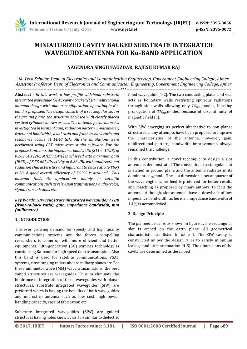
2. Design Principle The planned aerial is as shown in figure 1.The rectangular
slot is etched on the earth plane. All geometrical
characteristic are listed in table 1. The SIW cavity is
constructed as per the design rules to satisfy minimum
leakage and little attenuation [4-5]. The dimensions of the
cavity are determined as described
International Research Journal of Engineering and Technology (IRJET) e-ISSN: 2395-0056
Volume: 04 Issue: 07 | July -2017 www.irjet.net p-ISSN: 2395-0072
© 2017, IRJET | Impact Factor value: 5.181 | ISO 9001:2008 Certified Journal | Page 690
(a)
(b)
Fig -1: Geometry of the projected aerial (a) Front View (b)
Back View
in precious works of authors. First of all, the dimensions of a
conventional waveguide are calculated working in Ku-band.
Since for a conventional waveguide, lower and higher cutoff
frequencies are defined by
=1.25fc (1)
=1.89fc (2)
So, the cutoff frequency of conventional waveguide that
would work in required band will be 15.6 GHz. Using this
cutoff frequency, the broad wall dimension can thus be
calculated as
a= (3)
c = speed of light, relative permittivity, cutoff
frequency. The cutoff frequency of different modes is given
by
= (4)
For dominant mode; m=1, n=0
(5)
From here, the designing of the cavity start and the
equivalent SIW width can be calculated by dividing “a” with
, since now it will behave as a dielectric filled waveguide.
So, the width of the SIW equivalent to waveguide will have
dimension of
(6)
Next the calculations of the distance between the vias walls
is done to find out the center-to-center distance which is
given as
= (7)
Where “d” is the diameter of a via and “p” is the spacing
between two adjacent vias. The diameter and the spacing is
chosen according to the rules which are given as
d p≤2d (8)
0.05 ( (9)
d< /5 (10)
= (11)
= =2a (12)
Where is the cutoff wavelength and is the guided
wavelength
After calculating the dimensions of the cavity, designing the
feed line is the next target to achieve for best impedance
matching for least reflections. The feed width for
characteristic impedance of ohm, to match with that of the
port can be found from [6]. This is the conventional
approach to calculate the width of microstrip feed line for
any patch antenna. But here we have applied taper feed
technique. To calculate the taper feed dimensions, many

International Research Journal of Engineering and Technology (IRJET) e-ISSN: 2395-0056
Volume: 04 Issue: 07 | July -2017 www.irjet.net p-ISSN: 2395-0072
© 2017, IRJET | Impact Factor value: 5.181 | ISO 9001:2008 Certified Journal | Page 691
contributions have been proposed. Apart from taper feed,
several other techniques such as inset feed, coaxial feed,
modified taper feed etc. are prominent. Here, taper feed is
preferred as it acts as a transformer which matches the 50
ohm port feed with the impedance of the SIW cavity, whose
feed width calculations can be done from [7] as
= (13)
and, the dimensions of the feed at the port end can be
approximated as
~0.4 (14)
This implies that the width of the taper at the port end is
roughly 0.4 times the opening of the patch [8]. Here,
denotes the width at the feed end and is the opening
of the patch. W is the distance across of the patch and H is
the height of the substrate. The distance end to end of the
taper is given by
) n=1,2,3…… (15)
The substrate used here is Rogers/RT Duroid 5880 with =
2.2 and tallness of 0.787 mm having loss tangent 0.0009 and
the metal thickness is 0.0035mm. All the dimensions of the
designed aerial are tabulated in table 1. The length of the slot
is taken almost half of the guided wavelength.
Table -1: Parameters of design proposed
d = 0.66 ds = 8.5 h = 0.787 lf =3.9
lt =
2.635
ls = 7.8 p = 1 l =
15.495
wf =
2.42
ws = 0.2 wt = 5.5 w = 15.6
All lengths are in mm.
3. Results
The simulated and measured results are shown here. A
appreciable low return loss is reached pointing towards low
reflections and good impedance matching. The S-parameter
is plotted in figure 2, considering the conductor and
dielectric losses. From figure we can see that resonance
occurs at single frequency at 14.43 GHz.
The radiation pattern in different cut planes that is E-plane
(ϕ = 90°) and H-plane (ϕ = 0°) is shown in figure 3 which
shows the unidirectional pattern [9].
Fig -2: Simulated S11 of the proposed antenna.
E-Plane H-Plane
Fig -3: Calculated radiation patterns in different cut planes
at 14.43 GHz.
The inference of unidirectional pattern can be verified by the
front-to-back ratio which is quite high around 20. The
negative sign shows the direction that the radiator radiates
backwards or from backside.
Figure 5 provides us with the gain acquired by the antenna
which is 5.35 dBi and the bandwidth as calculated from
figure 2 is 202 MHz which shows that quite decent
performance characteristics are achieved by the antenna.
The antenna can be named as narrow-band antenna which is
a drawback of SIW antennas. But, it can be increased by

International Research Journal of Engineering and Technology (IRJET) e-ISSN: 2395-0056
Volume: 04 Issue: 07 | July -2017 www.irjet.net p-ISSN: 2395-0072
© 2017, IRJET | Impact Factor value: 5.181 | ISO 9001:2008 Certified Journal | Page 692
compromising gain, and then the latter can be increased
using arrays and polarizations [10].
Fig -4: Simulated Front-to-back ratio
Fig -5: Simulated Gain
Figure 6(a) shows the axial ratio which shows that the
antenna being horizontally polarized whereas figure 6(b)
and 6(c) shows the current distribution through the
structure and the rectangular slot respectively. It can be seen
that the current is evenly distributed throughout the antenna
confined within the boundations of the cylindrical vias. The
electric field gets cancelled as the direction of the current
along the horizontal boundary of the slot is having opposite
directions.
(a) (b)
(c)
Fig -6:. Simulated (a) Axial ratio (b) Surface current and
(c) Surface current through the slot
(a)
(b)
Fig -7: Parametric study of slot (a) width and (b) length

International Research Journal of Engineering and Technology (IRJET) e-ISSN: 2395-0056
Volume: 04 Issue: 07 | July -2017 www.irjet.net p-ISSN: 2395-0072
© 2017, IRJET | Impact Factor value: 5.181 | ISO 9001:2008 Certified Journal | Page 693
Figure 7 shows the parametric analysis of the various
parameters which are, the length in (a) keeping width
constant and the width in (b) keeping length constant and
the optimized results are obtained.
4. Conclusion
The antenna is compact in size having dimensions of 15.635
mm X 15.6 mm. The antenna is having unidirectional
radiation pattern. Rogers RT/ Duroid 5880 is chosen due to
its low property variations and better performance at higher
frequencies. Thus a low profile antenna is designed with
good performances characteristics radiating in Ku-band
which find its applications in satellites systems such TV
communications, radar applications etc. The designs comply
with all the design rules for the best results to be achieved.
The gain and bandwidth of the antenna can further be
improved by using arrays.
5. References
[1] Deslandes and K. Wu, “The Substrate Integrated
Waveguide (SIW) Concept, Technology and Applications,”
10th International Symposium on Microwave and Optical
Technology, Fukuoka, Japan, Aug. 2005.
[2] F. Xu and K. Wu, “Guided-wave and leakage
characteristics of substrate integrated waveguide,” IEEE
Trans. Microwave Theory Tech., vol. 53, no. 1, pp. 66–73, Jan.
2005.
[3] Guo Qing Luo, Member, IEEE, Zhi Fang Hu, Lin Xi Dong,
and Ling Ling Sun, Senior Member, IEEE, " Planar Slot
Antenna Backed by Substrate Integrated Waveguide Cavity
"IEEE Antenna and Wireless Propagation Letters , VOL. 7,
2008.
[4] A. Kumar, and S. Raghavan., Wideband slotted substrate
integrated waveguide cavity-backed antenna for Ku–band
application. Microwave and Optical Technology Letters,
2017, vol. 59, no. 7, p. 1613–1619. DOI: 10.1002/mop.30594.
[5] D. Deslandes and K. Wu, “Design consideration and
performance analysis of substrate integrated waveguide
components,” 32th European Microwave Conference, vol. 2,
Sept. 2002, pp. 881-884.
[6] A. Kumar, and S. Raghavan. "A Review: Substrate
Integrated Waveguide Antennas and Arrays." Journal of
Telecommunication, Electronic and Computer Engineering
(JTEC) 8.5 (2016): 95-104.
[7] Proceedings of the International Conference on Recent
Cognizance in Wireless Communication & Image Processing,
2016.
[8] Anja Skrivervik. "Broadband High Gain Small Array
Antenna for High Altitude Platforms Applications", 2007
IEEE 18th International Symposium on Personal Indoor and
Mobile Radio Communications, 09/2007.
[9] Soumava Mukherjee, Student Member, IEEE, Animesh
Biswas, Senior Member, IEEE, and Kumar Vaibhav
Srivastava, Senior Member, IEEE " Substrate Integrated
Waveguide Cavity-Backed Dumbbell-Shaped Slot Antenna
for Dual-Frequency Applications", IEEE, Antenna and
Wireless Propagation Letters ,VOL. 14, 2015.
[10] R. Bayderkhani, K. Forooraghi, Member,IEEE, and B.
Abbasi-Arand, Member,IEEE " Gain Enhanced SIW Cavity
backed Slot Antenna with Arbitrary Levels of Inclined
Polarization", IEEE Antennas and Wireless Propagation
Letters · January 2015.


![Miniaturized Triple Wideband CPW-Fed Patch Antenna With a ... · Double L-slot microstrip patch antenna array for WiMAX and WLAN applications is proposed in [20]. A coplanar waveguide](https://static.fdocuments.net/doc/165x107/5f14d7603b24ad1cb956d521/miniaturized-triple-wideband-cpw-fed-patch-antenna-with-a-double-l-slot-microstrip.jpg)