Miniature Scalp–Implantable Antennas for Telemetry in the ...
8
> AP1104-0437 < 1 Abstract— We study the design and radiation performance of novel miniature antennas for integration in head–implanted medical devices operating in the MICS (402.0–405.0 MHz) and ISM (433.1–434.8, 868.0–868.6 and 902.8–928.0 MHz) bands. A parametric model of a skin–implantable antenna is proposed, and a prototype is fabricated and tested. To speed–up antenna design, a two–step methodology is suggested. This involves approximate antenna design inside a simplified geometry and further Quasi– Newton optimization inside a canonical model of the intended implantation site. Antennas are further analyzed inside an anatomical human head model. Results indicate strong dependence of the exhibited radiation performance (radiation pattern, gain, specific absorption rate and quality of communication with exterior equipment) on design parameters and operation frequency. The study provides valuable insight into the design of implantable antennas, addressing the suitability of canonical against anatomical tissue models for design purposes, and assessing patient safety and link budget at various frequencies. Finite Element and Finite Difference Time Domain numerical solvers are used at different stages of the antenna design and analysis procedures to suit specific needs. The proposed design methodology can be applied to optimize antennas for several implantation scenarios and biotelemetry applications. Index Terms— Implantable antenna, industrial, scientific and medical band, medical implant communications service band, optimization, telemetry, specific absorption rate (SAR). I. INTRODUCTION MPLANTED medical devices are recently used to perform an expanding variety of diagnostic and therapeutic functions [1]–[4]. To be truly beneficial while preserving patient comfort, these devices need to communicate wirelessly with exterior equipment. Antenna–enabled biotelemetry for implants is gaining considerable attention in an attempt to overcome the limitations of inductive biotelemetry related to low data rate, restricted communication range and sensitivity to inter–coil misalignment [5], [6]. Implantable antenna design attracts high scientific interest to deal with the challenges of miniaturization, biocompatibility, impedance–matching, reliable data exchange and patient safety. Manuscript received April 18, 2011; revised February 20, 2012. A. Kiourti and K. S. Nikita are with the School of Electrical and Computer Engineering, National Technical University of Athens, Athens 15780, Greece (e–mail: [email protected], [email protected]). Various frequency bands are approved for medical implants. The medical implant communications service (MICS) band (402.0–405.0 MHz) is most commonly used, universally, for medical implant communications [7]. Circular [8] and square [9] stacked planar inverted–F antennas (PIFAs) have recently been presented for skin–implantation and biotelemetry in the MICS band, emphasizing on miniaturization and enhanced bandwidth. Simplified MICS half–wavelength dipoles [1], as well as MICS magnetic–type loop antennas [10] have also been reported for implantation inside the human head. The 433.1–434.8, 868–868.6 and 902.8–928.0 MHz industrial, scientific and medical (ISM) bands are additionally suggested for biotelemetry in some countries [11]. Quality of communication between electrically–short linear wire antennas has been assessed for artificial joint monitoring at 433 MHz [12]. Design and performance of a rectangular meandered PIFA for radio frequency identification (RFID) applications at 868 MHz has been investigated [13]. Radiation performance of a vaginally–located compact loop antenna, emulated as a forced single–cell excitation, has also been analyzed at 916.5 MHz [14]. In this study, the first challenge lies in proposing a fast two– step design methodology for implantable PIFAs. Antennas are initially designed inside a small single–tissue simulating cube, where simulations run fast, and further optimized inside a canonical model of the intended implantation site, using Quasi–Newton optimization [15]. Canonical tissue models have long been used to study bioelectromagnetic interactions [12], [16], [17]. A parametric model of a skin–implantable PIFA is suggested and experimentally validated, and scalp– implantable antennas are designed for biotelemetry at 402, 433, 868, and 915 MHz following the proposed methodology (e.g. pressure monitoring, brain wave sensing for the paralyzed, brain edema evolution monitoring, position trac- king, stroke rehabilitation, RFIDs etc). Optimized PIFAs are further implanted and analyzed inside an anatomical human head model. The proposed antennas occupy identical miniaturized physical (but not effective) dimensions. Antenna miniaturization shrinks the size of the implant accordingly. The second challenge lies in comparing the radiation performance of the scalp–implantable PIFAs. This involves evaluation of the exhibited radiation pattern and gain values, compliance with international guidelines for the specific Miniature Scalp–Implantable Antennas for Telemetry in the MICS and ISM Bands: Design, Safety Considerations and Link Budget Analysis Asimina Kiourti, Student Member, IEEE, and Konstantina S. Nikita, Senior Member, IEEE I
Transcript of Miniature Scalp–Implantable Antennas for Telemetry in the ...

> AP1104-0437 <
1
Abstract— We study the design and radiation performance of
novel miniature antennas for integration in head–implanted medical devices operating in the MICS (402.0–405.0 MHz) and ISM (433.1–434.8, 868.0–868.6 and 902.8–928.0 MHz) bands. A parametric model of a skin–implantable antenna is proposed, and a prototype is fabricated and tested. To speed–up antenna design, a two–step methodology is suggested. This involves approximate antenna design inside a simplified geometry and further Quasi–Newton optimization inside a canonical model of the intended implantation site. Antennas are further analyzed inside an anatomical human head model. Results indicate strong dependence of the exhibited radiation performance (radiation pattern, gain, specific absorption rate and quality of communication with exterior equipment) on design parameters and operation frequency. The study provides valuable insight into the design of implantable antennas, addressing the suitability of canonical against anatomical tissue models for design purposes, and assessing patient safety and link budget at various frequencies. Finite Element and Finite Difference Time Domain numerical solvers are used at different stages of the antenna design and analysis procedures to suit specific needs. The proposed design methodology can be applied to optimize antennas for several implantation scenarios and biotelemetry applications. Index Terms— Implantable antenna, industrial, scientific and
medical band, medical implant communications service band, optimization, telemetry, specific absorption rate (SAR).
I. INTRODUCTION
MPLANTED medical devices are recently used to perform an expanding variety of diagnostic and therapeutic functions
[1]–[4]. To be truly beneficial while preserving patient comfort, these devices need to communicate wirelessly with exterior equipment. Antenna–enabled biotelemetry for implants is gaining considerable attention in an attempt to overcome the limitations of inductive biotelemetry related to low data rate, restricted communication range and sensitivity to inter–coil misalignment [5], [6]. Implantable antenna design attracts high scientific interest to deal with the challenges of miniaturization, biocompatibility, impedance–matching, reliable data exchange and patient safety.
Manuscript received April 18, 2011; revised February 20, 2012. A. Kiourti and K. S. Nikita are with the School of Electrical and Computer
Engineering, National Technical University of Athens, Athens 15780, Greece (e–mail: [email protected], [email protected]).
Various frequency bands are approved for medical implants. The medical implant communications service (MICS) band (402.0–405.0 MHz) is most commonly used, universally, for medical implant communications [7]. Circular [8] and square [9] stacked planar inverted–F antennas (PIFAs) have recently been presented for skin–implantation and biotelemetry in the MICS band, emphasizing on miniaturization and enhanced bandwidth. Simplified MICS half–wavelength dipoles [1], as well as MICS magnetic–type loop antennas [10] have also been reported for implantation inside the human head. The 433.1–434.8, 868–868.6 and 902.8–928.0 MHz industrial, scientific and medical (ISM) bands are additionally suggested for biotelemetry in some countries [11]. Quality of communication between electrically–short linear wire antennas has been assessed for artificial joint monitoring at 433 MHz [12]. Design and performance of a rectangular meandered PIFA for radio frequency identification (RFID) applications at 868 MHz has been investigated [13]. Radiation performance of a vaginally–located compact loop antenna, emulated as a forced single–cell excitation, has also been analyzed at 916.5 MHz [14].
In this study, the first challenge lies in proposing a fast two–step design methodology for implantable PIFAs. Antennas are initially designed inside a small single–tissue simulating cube, where simulations run fast, and further optimized inside a canonical model of the intended implantation site, using Quasi–Newton optimization [15]. Canonical tissue models have long been used to study bioelectromagnetic interactions [12], [16], [17]. A parametric model of a skin–implantable PIFA is suggested and experimentally validated, and scalp–implantable antennas are designed for biotelemetry at 402, 433, 868, and 915 MHz following the proposed methodology (e.g. pressure monitoring, brain wave sensing for the paralyzed, brain edema evolution monitoring, position trac-king, stroke rehabilitation, RFIDs etc). Optimized PIFAs are further implanted and analyzed inside an anatomical human head model. The proposed antennas occupy identical miniaturized physical (but not effective) dimensions. Antenna miniaturization shrinks the size of the implant accordingly.
The second challenge lies in comparing the radiation performance of the scalp–implantable PIFAs. This involves evaluation of the exhibited radiation pattern and gain values, compliance with international guidelines for the specific
Miniature Scalp–Implantable Antennas for Telemetry in the MICS and ISM Bands: Design, Safety Considerations and Link Budget Analysis
Asimina Kiourti, Student Member, IEEE, and Konstantina S. Nikita, Senior Member, IEEE
I

> AP1104-0437 <
2
absorption rate (SAR) (IEEE C95.1–1999 [18] and IEEE C95.1–2005 [19]), and quality of communication with exterior equipment. Our goal is to evaluate dependency of the PIFAs’ radiation performance upon operation frequency and size.
Design and analysis is thus presented for scalp–implantable PIFAs at four frequency bands. In the literature, a 2.45 GHz PIFA [4] and a MICS loop antenna [10] have been presented for scalp–implantation, but no comparison with other frequency bands was reported. Comparative analyses of implantable antennas operating at various frequencies have been performed in [14] and [20]. In these studies, vagina and gastric/bladder/cardiac implants were presented, respectively, and evaluated at two frequency bands. In both papers, single cell excitation was considered to calculate radiation patterns and inherent net body losses. The studies did not address safety issues. A comparative study for scalp–implantable loop and short dipole antennas was reported in [21] considering four frequency bands. Comparison was limited to the exhibited radiation patterns and gains, while antenna (both physical and effective) dimensions were not scaled to each frequency band.
In this paper, an attempt is made to provide valuable insight into implantable PIFA design and selection of biotelemetry frequency. Simulations based on the Finite Element (FE) and Finite Difference Time Domain (FDTD) methods [22] are carried out within different stages of the antenna design and analysis procedures to suit specific needs. The paper is organized as follows. Section II describes the models and methods used in the study. Prototype fabrication and testing is performed in Section III. Numerical results are presented and discussed in Section IV. The paper concludes in Section V.
II. MODELS AND METHODS
A. Antenna Model A parametric model of a miniature PIFA is proposed for
skin–implantation, as shown in Fig. 1. The model consists of a 6 mm–radius ground plane and two 5 mm–radius vertically–stacked, meandered patches. Circular shape is chosen to avoid sharp edges. In actual applications, the antenna will be mounted on a medical implant device which will also serve as its ground plane. Throughout this study, the origin of the coordinate system is located at the center of the PIFA ground plane, according to Fig. 1. Rogers RO 3210 (permittivity, εr = 10.2, loss tangent, tanδ = 0.003), which has long been used in implantable antenna design, is chosen as the dielectric material [23]–[25]. Patches are printed on 0.6 mm–thick substrate layers and fed by a 50–Ohm coaxial cable (x = 0 mm, y = 4 mm). A 0.6 mm–thick superstrate layer covers the structure to preserve its biocompatibility and robustness. Patch stacking and meandering lengthen the effective current path, thus miniaturizing the antenna [26]. Meanders are equi–distant by 1 mm, and their width is fixed to 0.4 mm. Lengths of the meanders are considered variable and are denoted by the x coordinate (xij) of the points marked as {ij, i= A–F, j = l, u} in Fig. 1(b) and (c). A variably–positioned (x = xs, y = ys) shorting pin (radius of 0.3 mm) connects the ground plane with
the lower patch to further assist in miniaturization [26]. Tuning the xij, xs, and ys variables alters the effective antenna size and helps achieve the desired resonance characteristics.
B. Design Methodology To reduce simulation time, a two–step PIFA design
methodology is proposed, as summarized in Fig. 2. The basic idea is that since antennas are intended for skin–implantation, they can be approximately designed while in a simple skin–tissue simulating model [27], [28]. In this way, design is accelerated by two means: (1) scaling required to fine–tune the antenna inside the skin in case it was initially designed in free–space is avoided, and (2) shape and size of the surrounding skin–tissue model are found to insignificantly influence antenna resonance, and can, thus, be selected adequately simple and small to speed–up simulations. The reflection coefficient and target resonance frequency of the PIFA are denoted by S11 and f0, respectively.
In the first step, an initial, approximate design is performed. The PIFA is positioned in the center of a 100 mm–edge skin–tissue simulating cube (Fig. 3(a)), where simulations run fast. All thirteen xij, xs and ys variables of the parametric PIFA model are manually updated in an iterative way. The iterative procedure stops when
011 @ f (in skin cube)S 20 dB< − . (1)
Further implantation of the designed PIFA inside a specific
part of the body is expected to result in a slight, yet significant, frequency detuning. This phenomenon has been studied by the authors [27], [28], and is attributed to the loading of the surrounding tissues and exterior air on the antenna in each of the implantation scenarios.
In the second step, PIFA design is optimized for the implantation scenario under consideration. Quasi–Newton optimization is selected for its speed and accuracy in cases of insignificant numerical noise [15]. Optimization is performed inside a canonical model of the intended implantation site. To speed–up design, the position of the shorting pin (xs, ys) is kept fixed to that of the initial PIFA, and the eleven xij variables are only considered as dimensions in the solution space. These are initialized to the values obtained in the first step and vary within the range [–4.6 mm, 4.6 mm]. The minimum and maximum step values are set to 0.1 and 0.4 mm, respectively.
Fig. 1. Proposed parametric PIFA model: (a) ground plane, (b) lower patch, (c) upper patch, and (d) side view.

> AP1104-0437 <
3
The cost function is defined as
011 @ f (in canonical model)cost = |S | , (2)
and optimization terminates when Eq. (2) is minimized, or when the number of iterations exceeds 300. Noise involved in the calculation of the cost function is small enough (uncertainty in the calculation of the cost function is given by 0.02), justifying our choice for Quasi–Newton optimization.
C. Numerical Methods and Tissue Models Canonical tissue models are used in carrying out FE
simulations in Ansoft HFSS. The tetrahedron–shaped basic mesh element accelerates solving of curved geometries, while a Quasi–Newton optimizer is integrated into the platform. PIFA designs are validated through FDTD simulations in Remcom XFDTD, which enables efficient modeling of detailed anatomical human body parts. The antenna model is transferred to XFDTD in terms of exporting .sat files from HFSS, importing these into XFDTD, and re–meshing.
Optimization of scalp–implantable PIFAs is performed inside the scalp of a 100 mm–radius, 3–layer spherical human head model consisting of skin (scalp), cortical bone (skull) and grey matter (brain) tissues (Fig. 3(b)). Thickness of the scalp and skull layers is set to 0.5 cm, each [16]. Investigations within the scalp of a 13–tissue (Table I) anatomical human head model (Fig. 3(c) [28]) are also performed. In this way, PIFA design is validated for anatomically–based geometries and more realistic simulation results are obtained. Tissue dielectric properties (permittivity, εr, and conductivity, σ) used in this study are indicated in Table I [29]–[31], and approximated as constant inside a 200 MHz frequency range around f0. Using this approximation, the maximum errors of εr and σ at 402 MHz are given by 6.59% and 8.89%, respectively [28]. Accuracy is further improved at higher frequencies.
Simulation parameters are given as follows. Absorbing boundaries are set λ0/4 (λ0 is the free–space wavelength) away from all simulation set–ups in order to take free–space
radiation into account and extend radiation infinitely far. The FE solver automatically meshes the geometry in an iterative way. Meshing is perturbed by 30% between each pass, and the refinement procedure stops when the maximum change in |S11| between two consecutive passes is less than 0.02 or when the number of passes exceeds 10. The solver works in the frequency–domain, performing a 2000 point–frequency sweep by ±100 MHz around f0. In the FDTD simulations, biological tissue is meshed in 2.5 (skin–cube, canonical head) and 1.25 mm3 (anatomical head) cells. Non–cubical mesh of 0.1 mm × 0.1 mm × 0.2 mm is used for the PIFA in order to preserve accuracy in patch–surface modeling (the minimum step value of the optimizer equals 0.1 mm) without aimlessly delaying simulations (the 0.6 mm–thick dielectric layers can adequately be modeled in 0.2 mm steps). Cells of 3.5 mm in edge (∆x) model free–space so as to meet the FDTD spatial step constraint (∆x < λmin/10, where λmin indicates the wavelength of the highest frequency of interest) for all simulation set–ups. This sets the maximum simulation frequency (fmax) to 8.6 GHz (fmax = c / (10∆x), where c is the speed of light) and time step
(∆t) to 6.736 ps (∆t = ∆x/c 3 ), as referenced to free–space. In each set–up, the actual fmax will be determined by the highest–permittivity tissue material. Sinusoidal and Gaussian (pulse width of 32 time steps) sources are used for the single frequency and broadband simulations, respectively. Calculations continue until a 30 dB convergence is achieved.
III. PROTOTYPE AND ANTENNA MODEL VALIDATION
In order to validate the proposed PIFA model and verify simulation results, prototype testing is performed at 402 MHz. Following the first step of the design methodology described
TABLE I TISSUE DIELECTRIC PROPERTIES USED
Tissue type 402 MHz 433 MHz 868 MHz 915 MHz εr σ
[S/m] εr σ
[S/m] εr σ
[S/m] εr σ
[S/m] skin (scalp) 46.74 0.689 46.08 0.702 41.58 0.856 41.33 0.872 bone (skull) 13.10 0.090 13.07 0.094 12.48 0.139 12.44 0.145 dura 46.65 0.827 46.38 0.835 44.51 0.951 44.39 0.966 CSF 70.97 2.252 70.64 2.260 68.71 2.399 68.61 2.419 grey matter 57.39 0.738 56.83 0.751 52.88 0.929 52.65 0.949 white matter 42.05 0.445 41.67 0.454 38.99 0.581 38.84 0.595 muscle 57.11 0.797 56.87 0.805 55.11 0.932 54.99 0.948 cartilage 45.45 0.587 45.15 0.598 42.77 0.768 42.6 0.789 vitreous humor 69.00 1.529 68.99 1.534 68.91 1.627 68.89 1.641 lens 48.14 0.669 47.96 0.675 46.63 0.784 46.55 0.798 eye sclera 57.66 1.005 57.38 1.014 55.36 1.155 55.23 1.173 spinal cord 35.39 0.447 35.05 0.456 32.63 0.565 32.49 0.578 cerebellum 55.94 1.031 55.14 1.048 49.66 1.248 49.35 1.269
Fig. 3. Simulation set–ups of the PIFA implanted inside (a) a skin–tissue simulating cube, and the scalp of (b) a 3–layer spherical and (c) an anatomical human head model.
Fig. 2. Proposed two–step design methodology.
> AP1104-0437 <
4
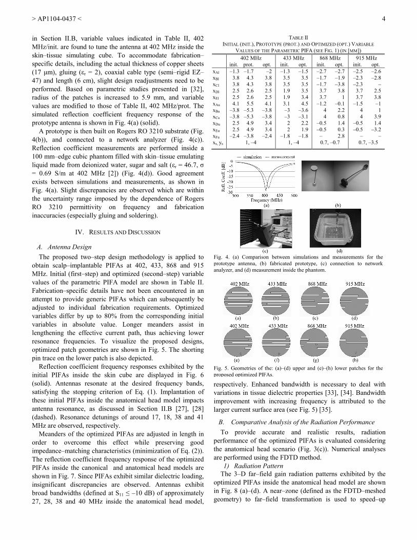
in Section II.B, variable values indicated in Table II, 402 MHz/init. are found to tune the antenna at 402 MHz inside the skin–tissue simulating cube. To accommodate fabrication–specific details, including the actual thickness of copper sheets (17 µm), gluing (εr = 2), coaxial cable type (semi–rigid EZ–47) and length (6 cm), slight design readjustments need to be performed. Based on parametric studies presented in [32], radius of the patches is increased to 5.9 mm, and variable values are modified to those of Table II, 402 MHz/prot. The simulated reflection coefficient frequency response of the prototype antenna is shown in Fig. 4(a) (solid).
A prototype is then built on Rogers RO 3210 substrate (Fig. 4(b)), and connected to a network analyzer (Fig. 4(c)). Reflection coefficient measurements are performed inside a 100 mm–edge cubic phantom filled with skin–tissue emulating liquid made from deionized water, sugar and salt (εr = 46.7, σ = 0.69 S/m at 402 MHz [2]) (Fig. 4(d)). Good agreement exists between simulations and measurements, as shown in Fig. 4(a). Slight discrepancies are observed which are within the uncertainty range imposed by the dependence of Rogers RO 3210 permittivity on frequency and fabrication inaccuracies (especially gluing and soldering).
IV. RESULTS AND DISCUSSION
A. Antenna Design The proposed two–step design methodology is applied to
obtain scalp–implantable PIFAs at 402, 433, 868 and 915 MHz. Initial (first–step) and optimized (second–step) variable values of the parametric PIFA model are shown in Table II. Fabrication–specific details have not been encountered in an attempt to provide generic PIFAs which can subsequently be adjusted to individual fabrication requirements. Optimized variables differ by up to 80% from the corresponding initial variables in absolute value. Longer meanders assist in lengthening the effective current path, thus achieving lower resonance frequencies. To visualize the proposed designs, optimized patch geometries are shown in Fig. 5. The shorting pin trace on the lower patch is also depicted.
Reflection coefficient frequency responses exhibited by the initial PIFAs inside the skin cube are displayed in Fig. 6 (solid). Antennas resonate at the desired frequency bands, satisfying the stopping criterion of Eq. (1). Implantation of these initial PIFAs inside the anatomical head model impacts antenna resonance, as discussed in Section II.B [27], [28] (dashed). Resonance detunings of around 17, 18, 38 and 41 MHz are observed, respectively.
Meanders of the optimized PIFAs are adjusted in length in order to overcome this effect while preserving good impedance–matching characteristics (minimization of Eq. (2)). The reflection coefficient frequency response of the optimized PIFAs inside the canonical and anatomical head models are shown in Fig. 7. Since PIFAs exhibit similar dielectric loading, insignificant discrepancies are observed. Antennas exhibit broad bandwidths (defined at S11 ≤ –10 dB) of approximately 27, 28, 38 and 40 MHz inside the anatomical head model,
respectively. Enhanced bandwidth is necessary to deal with variations in tissue dielectric properties [33], [34]. Bandwidth improvement with increasing frequency is attributed to the larger current surface area (see Fig. 5) [35].
B. Comparative Analysis of the Radiation Performance To provide accurate and realistic results, radiation
performance of the optimized PIFAs is evaluated considering the anatomical head scenario (Fig. 3(c)). Numerical analyses are performed using the FDTD method.
1) Radiation Pattern The 3–D far–field gain radiation patterns exhibited by the
optimized PIFAs inside the anatomical head model are shown in Fig. 8 (a)–(d). A near–zone (defined as the FDTD–meshed geometry) to far–field transformation is used to speed–up
Fig. 5. Geometries of the: (a)–(d) upper and (e)–(h) lower patches for the proposed optimized PIFAs.
Fig. 4. (a) Comparison between simulations and measurements for the prototype antenna, (b) fabricated prototype, (c) connection to network analyzer, and (d) measurement inside the phantom.
TABLE II INITIAL (INIT.), PROTOTYPE (PROT.) AND OPTIMIZED (OPT.) VARIABLE
VALUES OF THE PARAMETRIC PIFA (SEE FIG. 1) (IN [MM]) 402 MHz 433 MHz 868 MHz 915 MHz
init. prot. opt. init. opt. init. opt. init. opt. xAl –1.3 –1.7 –2 –1.3 –1.5 –2.7 –2.7 –2.5 –2.6 xBl 3.8 4.3 3.8 3.5 3.5 –1.7 –1.9 –2.3 –2.8 xCl 3.8 4.3 3.8 3.5 3.5 –1.7 –3.8 –2.3 – xDl 2.5 2.6 2.5 1.9 3.5 3.7 3.8 3.7 2.5 xEl 2.5 2.6 2.5 1.9 3.4 3.7 1 3.7 3.8 xAu 4.1 5.5 4.1 3.1 4.5 –1.2 –0.1 –1.5 –1 xBu –3.8 –5.3 –3.8 –3 –3.6 4 2.2 4 1 xCu –3.8 –5.3 –3.8 –3 –3.1 4 0.8 4 3.9 xDu 2.5 4.9 3.4 2 2.2 –0.5 1.4 –0.5 1.4 xEu 2.5 4.9 3.4 2 1.9 –0.5 0.3 –0.5 –3.2 xFu –2.4 –3.8 –2.4 –1.8 –1.8 – 2.8 – – xs, ys 1, –4 1, –4 0.7, –0.7 0.7, –3.5

> AP1104-0437 <
5
calculations. Since the anatomical head model is an asymmetrical, inhomogeneous dielectric structure, radiation patterns, which depend on the structure and shape of the implantation site, are not symmetric either. Increased tissue absorption at high frequencies causes attenuation which deteriorates symmetry, and is consistent with the findings in [36], [37]. For comparison, the far–field radiation patterns of the initial PIFAs inside the skin cube are highly symmetric (Fig. 8 (e)–(h)). Shadowing is reduced due to the size of the implanting environment. Since PIFAs are electrically very small and symmetrically surrounded by a homogeneous medium, they radiate nearly omni–directional, monopole–like patterns. Because of the small PIFA size and high tissue loss, low values of gain are recorded, as indicated in Table III. High gain values at increased frequencies are attributed to the larger current surface area of the PIFAs (see Fig. 5) [35].
2) SAR and Maximum Allowable Input Power International and national guidelines set the maximum
allowable values for the SAR in an attempt to preserve patient safety. For example, the ICNIRP basic restrictions limit the SAR averaged over 10 g of contiguous tissue to less than 2 W/kg [38]. The IEEE C95.1–1999 standard restricts the SAR averaged over any 1 g of tissue in the shape of a cube (1 g–avg SAR) to less than 1.6 W/kg [18]. To harmonize with the ICNIRP guidelines, the IEEE C95.1–2005 standard restricts the SAR averaged over any 10 g of tissue in the shape of a cube (10–g avg SAR) to less than 2 W/kg [19].
In this study, conformance with the latest IEEE standards ([18], [19]) is assessed, and mass–averaging procedures recommended by IEEE are applied [39]. Net–input power to the PIFAs is initially set to 1 W. Maximum 1 g–avg and 10 g–avg SAR values computed in this case are shown in Table IV, along with the maximum allowable net–input power levels which satisfy the IEEE restrictions for the SAR. The IEEE C95.1–1999 standard is found to be much stricter, limiting the net–input power to more than 6 times lower than that imposed by the IEEE C95.1–2005 standard. Local SAR distributions
generated in the surrounding tissues are shown in Fig. 9, for the FDTD slices where maximum local SAR values have been calculated. For comparison purposes, the same net–input power of 4.927 mW is considered for the PIFAs, and all results are normalized to 2 W/kg.
Simulation results presented in Fig. 9 are justified by the identical physical but varying effective dimensions of the proposed PIFAs. At higher operation frequencies, electric field, or, equivalently, current density, is more uniformly distributed across an increased surface area of the radiating patches, as dictated by the corresponding geometry (see Fig. 5). Lower maximum SAR values along with more expanded
Fig. 9. Local SAR distribution in the (a) xy, (b) xz, (c) yz slices of the anatomical head model (Fig. 3(c)) in which maximum local SAR has been calculated (net–input power = 4.927 mW).
TABLE IV MAXIMUM SAR (NET–INPUT POWER = 1 W), AND MAXIMUM ALLOWABLE NET–INPUT POWER FOR THE OPTIMIZED PIFAS IN THE ANATOMICAL HEAD
f0 [MHz]
max SAR [W/kg] max net–input power [mW] 1 g–avg 10 g–avg C95.1–1999 [18] C95.1–2005 [19]
402 324.74 66.612 4.927 30.02 433 309.74 66.382 5.166 30.13 868 296.94 66.048 5.388 30.28 915 294.86 65.764 5.426 30.41
Fig. 7. Reflection coefficient frequency response of the optimized PIFAs inside the spherical (Fig. 3(b)) and anatomical head models (Fig. 3(c)).
Fig. 6. Reflection coefficient frequency response of the initial PIFAs inside the skin cube (Fig. 3(a)) and the anatomical head model (Fig. 3(c)).
TABLE III MAXIMUM (GMAX), MINIMUM (GMIN) AND AVERAGE (GAVG) GAIN VALUES
ACHIEVED (IN [DB]) f0
[MHz] anatomical head skin cube anatomical head xy – plane
Gmax Gmax Gmax Gmin Gavg 402 –36.90 –33.00 –36.74 –38.02 –37.33 433 –35.99 –29.56 –36.62 –41.45 –38.47 868 –35.14 –22.35 –37.08 –41.09 –39.02 915 –32.94 –19.88 –33.41 –42.28 –37.66
Fig. 8. 3–D far–field gain radiation patterns of: (a)–(d) the optimized PIFAs inside the anatomical head model (Fig. 3(c)), and (e)–(h) the initial PIFAs inside the skin cube (Fig. 3(a)).

> AP1104-0437 <
6
field distribution in the surrounding tissues are, thus, recorded. Similar results have been reported for ingestible antennas at various frequency bands in which physical dimensions were not scaled proportionally for each scenario under consideration [37]. However, in case of physically–scaled antennas, high operation frequencies and, thus, tissue conductivities, would be expected to result in increased SAR values and more concentrated SAR distributions [14].
1) Characterization of the Communication Link Bi–directional, half–duplex communication is established
between the optimized PIFAs and exterior antennas. In up–link transmission, the implanted and exterior antennas act as the transmitting (Tx) and receiving antennas (Rx), respectively. Tx and Rx roles interchange for down–link transmission.
Assuming far–field communication, the link power budget can be described in terms of
[ ] [ ] [ ] [ ] [ ]Rx Tx Tx RxdBm dBm dB dB dBmP P G G loss= + + − (3)
where PRx is the power received by the Rx, PTx is the power available at the Tx, GTx, GRx are the gains of the Tx and Rx, respectively, and
[ ] [ ] [ ] [ ]p Tx RxdBm dBm dBm dBmdBmloss PL e ML ML = + + + (4)
where PL is the path–loss, ep is the polarization mismatch factor and MLTx, MLRx are the Tx and Rx impedance mismatch losses, respectively [42]. PL can be calculated by the log–distance model as
[ ] [ ]2
0dBm dB
0 0
4 ddPL 10n log 10log s
d λπ
= + +
(5)
where n is the path loss exponent, d is the Tx–Rx distance, λ0 is the free–space wavelength, d0 ≤ d is a reference distance and s is the random scatter around the mean [41]. In case of free–space propagation n = 2 (and Eq. (3) simplifies to the Friis equation), while for indoor–propagation n is environment–dependant.
In this study, we consider exterior half–wavelength dipole antennas (gain of 2.15 dB [40]) centered around the xy–plane, at a distance of d = 1–6 m. The azimuthal (xy–plane) radiation patterns of the optimized PIFAs inside the anatomical head model are shown in Fig. 10. Maximum (Gmax), minimum (Gmin) and average (Gavg) azimuthal gain values are recorded in Table III. Four communication scenarios are studied: (a) best–case free–space propagation (Gmax, n = 2) (b) worst–case free–space propagation (Gmin, n = 2), (c) line–of–sight (LOS) indoor propagation (Gavg, n = 1.5, d0 = 1 m, [s]dB = 0) [25], and (d) non–line–of–sight (NLOS) indoor propagation (Gavg, n = 3, d0 = 1 m, [s]dB = 0) [42]. Dipole antennas are assumed to be well–matched, so that their impedance mismatch losses can be approximated as 0 dB. Polarization mismatch losses (ep) are also neglected.
In up–link transmission, the maximum allowable PTx is
limited by the safety guidelines for the SAR. To mitigate EM interference with other services, regulations restricting the effective isotropic radiated power (EIRP) of implantable antennas also confine their input power (EIRP ≤ EIRPmax, where EIRPmax = –16 dBm, 7.85 dBm, 11.85 dBm and 36 dBm, for f0 = 402MHz, 433 MHz, 868 MHz and 915 MHz, respectively [11], [43]). However, gain values exhibited by the
Fig. 11. Power received by exterior dipole antennas (Pr) versus Tx–Rx distance for the optimized PIFAs tuned at (a) 402 MHz, (b) 433 MHz, (c) 868 MHz, and (d) 915 MHz, considering four transmission scenarios.
Fig. 10. Azimuthal (xy–plane) far–field gain radiation patterns of the optimized PIFAs inside the anatomical head model (Fig. 3(c)).

> AP1104-0437 <
7
proposed PIFAs are low enough, so that the maximum allowable power is determined by the regulated SAR limitations. The maximum allowable net–input power levels calculated in Table IV (IEEE C95.1–1999 standard) are, thus, considered. Values of PRx, (or, equivalently, the required Rx sensitivity) versus distance are shown in Fig. 11, for all frequency and transmission scenarios under study.
PIFA operation frequency is found to not significantly alter the quality of the communication link. Even though enhanced gain values were observed at higher frequencies (Fig. 8, Table III), here we only consider the GTx values achieved in the xy–plane. These are found to be comparable, regardless of the operation frequency (see Table III). Furthermore, results show that for the 402, 433 and 868 MHz PIFAs, indoor LOS links are more reliable, followed by the best–case free–space, worst–case free–space and indoor NLOS links. Discrepancies in the communication performance of the 915 MHz PIFA are attributed to the relatively high deviation between the exhibited Gmax and Gavg values, as compared to the other frequency scenarios under consideration.
Quality of down–link transmission can be evaluated in the same way. In this case, however, PTx is limited by the EIRP restrictions, so that
[ ] [ ] [ ] [ ]Tx max Tx maxdBm dBm dB dBmP EIRP G EIRP 2.15≤ − = − (6)
Simulations indicate that SAR does not become an issue for
the communication scenarios under study and the PTx values given by Eq. (6). Reliability of the down–link is expected to improve with increasing frequency because of higher allowable EIRP values.
V. CONCLUSION
Based on a parametric model of a skin–implantable PIFA and a fast two–step design methodology, we proposed miniature scalp–implantable PIFAs at 402, 433, 868, and 915 MHz. Antennas exhibit identical volume of π × 62 × 1.8 mm3 and broad 10 dB–bandwidths of 27, 28, 38 and 40 MHz.
Insignificant discrepancies were observed in the antenna resonance performance within canonical and anatomical tissue models, and analysis inside a 13–tissue anatomical head model was performed. PIFAs at higher frequencies were found to achieve enhanced gains (10.7% increase at 915 MHz as compared to 402 MHz), reduced SAR values (9.2% and 1.3% decrease in the 1 g– and 10 g–avg SAR), increased maximum allowable net–input power levels (10.1% and 1.3% increase imposed by [18] and [19]), and more expanded SAR distributions. Results are attributed to our choice of keeping the PIFAs’ physical dimensions identical and modifying their effective size. Improved down–link communication was shown with increasing frequency because of more relaxed EIRP restrictions, while minor frequency dependence was found for the up–link scenarios under study.
Use of different numerical solvers within stages of the antenna design and analysis procedures with different
requirements was highlighted. The proposed design methodology can be adjusted to suit several antenna models and implantation scenarios.
ACKNOWLEDGMENT
The authors would like to gratefully thank Dr. C. Fernandes and Dr. J. Costa for providing the facilities of Instituto de Telecommunicações, Instituto Superior Técnico, Lisbon, Portugal, and helping with the prototype fabrication.
REFERENCES [1] J. Kim, and Y. Rahmat-Samii, “Implanted antennas inside a human
body: simulations, designs and characterizations,” IEEE Trans. Microw. Theory Tech., vol. 52, pp. 1934–1943, Aug. 2005.
[2] T. Karacolak, A. Z. Hood, and E. Topsakal, “Design of a dual-band implantable antenna and development of skin mimicking gels for continuous glucose monitoring,” IEEE Trans. Microw. Theory Tech., vol. 56, pp. 1001–1008, Apr. 2008.
[3] M. Z. Azad and M. Ali, “A miniature implanted inverted-F antenna for GPS application,” IEEE Trans. Antennas Propag., vol. 57, pp. 1854–1858, Jun. 2009.
[4] R. Warty, M.-R. Tofighi, U. Kawoos, and A. Rosen, “Characterization of implantable antennas for intracranial pressure monitoring: reflection by and transmission through a scalp phantom,” IEEE Trans. Microw. Theory Tech., vol. 56, pp. 2366–2376, Oct. 2008.
[5] W. G. Scanlon, N. E. Evans, and J. B. Burns, “FDTD analysis of closed coupled 418 MHz radiating devices for human biotelemetry,” Phys. Med. Biol., vol. 44, pp. 335–345, 1999.
[6] G. C. Crumley, N. E. Evans, J. B. Burns, and T. G. Trouton, “On the design and assessment of a 2.45 GHz radio telecommand system for remote patient monitoring,” Med. Eng. Phys., vol. 20, pp. 750–755, Mar. 1999.
[7] “Medical implant communications service (MICS) federal register,” Rules Reg., vol. 64, no. 240, pp. 69926–69934, Dec. 1999.
[8] W.-C. Liu, W.-H. Chen, and C.-M. Wu, “Implantable broadband circular stacked PIFA antenna for biotelemetry communication,” J. of Electromagn. Waves and Appl., vol. 22, pp. 1791–1800, 2008.
[9] W.-C. Liu, S.-H. Chen, and C.-M. Wu, “Bandwidth enhancement and size reduction of an implantable PIFA antenna for biotelemetry devices,” Microw. Opt. Technol. Lett., vol. 51, pp. 755–757, Mar. 2009.
[10] Z. N. Chen, G. C. Liu, and T. S. P. See, “Transmission of RF signals between MICS loop antennas in free space and implanted in the human head,” IEEE Trans. Antennas Propag., vol. 57, pp. 1850–1853, Jun. 2009.
[11] “International Telecommunications Union-Radiocommunications (ITU-R), radio regulations, section 5.138 and 5.150,” ITU, Geneva, Switzerland. [Online]. Available: http://itu.int/home
[12] M. D. Weiss, J. L. Smith, and J. Bach, “RF coupling in a 433-MHz biotelemetry system for an artificial hip,” IEEE Antennas Wireless Propag. Lett., vol. 8, pp. 916–919, 2009.
[13] A. Sani, M. Rajab, R. Foster, and Y. Hao, “Antennas and propagation of implanted RFIDs for pervasive healthcare applications,” Proc. IEEE, vol. 98, pp. 1648–1655, Sept. 2010.
[14] W. G. Scanlon, J. B. Burns, and N. E. Evans, “Radiowave propagation from a tissue-implanted source at 418 MHz and 916.5 MHz,” IEEE Trans. Biomed. Eng., vol. 47, pp. 527–534, Apr. 2000.
[15] W. Sun and Y.-X. Yuan, “Optimization theory and methods,” Ed. Springer, 2006, ch. 5.
[16] S. Koulouridis and K. S. Nikita, “Study of the coupling between human head and cellular phone helical antennas,” IEEE Trans. Electromagn. Compat., vol. 46, no. 1, pp. 62–70, 2004.
[17] K. S. Nikita, G. D. Mitsis, and N. K. Uzunoglu, “Analysis of focusing of pulsed baseband signals inside a layered tissue medium,” IEEE Trans. Microw. Theory Tech., vol. 48, pp. 30–39, Jan. 2000.
[18] IEEE Standard for Safety Levels with Respect to Human Exposure to Radiofrequency Electromagnetic Fields, 3kHz to 300 GHz, IEEE Standard C95.1, 1999.

> AP1104-0437 <
8
[19] IEEE Standard for Safety Levels with Respect to Human Exposure to Radiofrequency Electromagnetic Fields, 3kHz to 300 GHz, IEEE Standard C95.1, 2005.
[20] A. Sani, A. Alomainy, and Y. Hao, “Numerical characterization and link budget evaluation of wireless implants considering different digital human phantoms,” IEEE Trans. Microw. Theory Tech., vol. 57, pp. 2605–2613, Oct. 2009.
[21] C. A. Roopnariane, M.-R Tofighi, and C. M. Collins, “Radiation performance of small implanted antennas in head at MICS, ISM, and GPS bands,” in Proc. IEEE 36th Annu. Northeast Bioeng. Conf., New York, 2010, pp. 1–2.
[22] M. N. O. Sadiku, “Numerical techniques in electromagnetics”, 2nd ed., Ed. CRC Press, 2001, ch. 3, 6.
[23] C. M. Lee, T. C. Yo, F. J. Huand, and C. H. Luo, “Bandwidth enhancement of planar inverted–F antenna for implantable biotelemetry,” Microw. Opt. Technol. Lett., vol. 51, pp. 749–752, Mar. 2009.
[24] V. M. Lee, T. C. Yo, and C. H. Luo, “Compact broadband stacked implantable antenna for biotelemetry with medical devices,” in Proc. IEEE Annu. Wireless Microw. Tech. Conf., Clearwater Beach, FL, 2006, pp. 1–4.
[25] W.-C. Liu, F.-M. Yeh, and M. Ghavami, “Miniaturized implantable broadband antenna for biotelemetry communication,” Microw. Opt. Technol. Lett., vol. 50, pp. 2407–2409, Sep. 2008.
[26] K.-L Wong, “Compact and broadband microstrip antennas,” John Wiley & Sons, 2002.
[27] A. Kiourti, M. Christopoulou, S. Kouloudis, and K. S. Nikita, “Design of a novel miniaturized PIFA for biomedical telemetry,” in Proc. ICST Int. Conf. Wireless Mobile Commun. Healthcare, Ayia Napa, Cyprus, 2010, pp. 127–134.
[28] A. Kiourti, M. Christopoulou, and K. S. Nikita, “Performance of a novel miniature antenna implanted in the human head for wireless biotelemetry,” in Proc. IEEE Int. Symp. Antennas Propag., Spokane, Washington, 2011, pp. 392–395.
[29] C. Gabriel, S. Gabriel, and E. Corthout, “The dielectric properties of biological tissues: I. Literature survey,” Phys. Med. Biol., vol. 41, pp. 2231–2249, 1996.
[30] S. Gabriel, R. W. Lau, and C. Gabriel, “The dielectric properties of biological tissues: II. Measurements in the frequency range 10 Hz to 20 GHz,” Phys. Med. Biol., vol. 41, pp. 2251–2269, 1996.
[31] S. Gabriel, R. W. Lau, and C. Gabriel, “The dielectric properties of biological tissues: III. Parametric models for the dielectric spectrum of tissues,” Phys. Med. Biol., vol. 41, pp. 2271–2293, 1996.
[32] A. Kiourti, M. Tsakalakis, and K. S. Nikita, “Parametric study and design of implantable PIFAs for wireless biotelemetry,” in Proc. 2nd ICST Int. Conf. Wireless Mobile Commun. Healthcare, Kos Island, Greece, 2011, pp. 96–102.
[33] J. Z. Bao, S. T. Lu, and W. D. Hurt, “Complex dielectric measurements and analysis of brain tissues in the radio and microwave frequencies,” IEEE Trans. Microw. Theory Tech., vol. 45, no. 10, pp. 1730–1741, Oct. 1997.
[34] C. Gabriel and A. Peyman, “Dielectric measurement: Error analysis and assessment of uncertainty,” Phys. Med. Biol., vol. 51, pp. 6033–6046, 2006.
[35] D. T. Notis, P. C. Liakou, and D. P. Chrissoulidis, “Dual polarized microstrip patch antenna, reduced in size by use of peripheral slits,” in Proc. Europ. Conf. on Wireless Technol., Amsterdam, 2004, pp. 125–128.
[36] L. C. Chirwa, P. A. Hammond, S. Roy, and D. R. S. Cumming, “Electromagnetic radiation from ingested sources in the human intestine between 150 MHz and 1.2 GHz,” IEEE Trans. Biomed. Eng., vol. 50, pp. 484–492, Apr. 2003.
[37] L. Xu, M. Q.-H. Meng, H. Ren, and Y. Chen, “Radiation characteristics of ingestible wireless devices in human intestine following radio frequency exposure at 430, 800, 1200, and 2400 MHz,” IEEE Trans. Antennas Propag., vol. 57, pp. 2418–2428, Aug. 2009.
[38] International Commission on Non-Ionizing Radiation Protection, “Guidelines for limiting exposure to time–varying electric, magnetic, and electromagnetic fields (up to 300 GHz),” Health Phys., vol. 74, pp. 494–522, 1998.
[39] IEEE Recommended Practice for Measurements and Computations of Radio Frequency Electromagnetic Fields with Respect to Human
Exposure to such Fields, 100 kHz to 300 GHz, IEEE Standard C95.3–2002, 2002.
[40] C. A. Balanis, Antenna Theory: Analysis and Design, 2nd ed. New York: Wiley, 2002.
[41] A. Alomainy and Y. Hao, “Modeling and characterization of biotelemetric radio channel from ingested implants considering organ contents,” IEEE Trans. Antennas Propag., vol. 57, pp. 999–1005, Apr. 2009.
[42] European Cooperative in the Field of Science and Technical Research, Urban Transmission Loss Models for Mobile Radio in the 900 and 1800 MHz Band, The Hague, The Netherlands, EURO–COST 231, Sep. 1991, rev. 2.
[43] “Recommendation ITU–R SA.1346,” Int. Telecommun. Union, Geneva, Switzerland, 1998.
Asimina Kiourti (S’10) received the Diploma degree in electrical and computer engineering from the University of Patras, Patras, Greece (2008), and the MSc degree in broadband communications from University College London, London, U.K. (2009).
She has been a member of the Biomedical Simulations and Imaging Laboratory, National Technical University of Athens, Athens, Greece, since October 2009, where she is currently working towards her Ph.D. She has (co–) authored 1 book
chapter and 9 journal and conference papers. Her research interests include antenna theory, biomedical telemetry and electromagnetics.
Ms. Kiourti has been a recipient of the IEEE Antennas and Propagation Society Doctoral Research Award. She is a reviewer at the IEEE Antennas and Wireless Propagation Letters and the IEEE Antennas and Propagation Magazine. She has served on the organizing committee of three international conferences. She is a member of the Technical Chamber of Greece.
Konstantina S. Nikita (M’96–SM’00) received the Diploma in electrical engineering and the Ph.D. degree from the National Technical University of Athens (NTUA), as well as the M.D. degree from the Medical School, University of Athens.
From 1990 to 1996, she worked as a Researcher at the Institute of Communication and Computer Systems. In 1996, she joined the School of Electrical and Computer Engineering, NTUA, as an Assistant Professor, and since 2005 she serves as a Professor
at the same School. She has authored or co-authored 160 papers in refereed international journals and chapters in books, and over 280 papers in international conference proceedings. She is editor or co-editor of two books in English, and author or co-author of two books in Greek. She holds two patents. She has been the technical manager of several European and National R&D projects. She has been honorary chair/ chair of the program/organizing committee of several international conferences on the same fields and she has served as keynote/invited speaker at international conferences, symposia and workshops organized by NATO, WHO, ICNIRP, IEEE, URSI, COMCON, PIERS etc. She has been the advisor of 20 completed Ph.D. theses, several of which have received various awards. Her current research interests include biomedical signal and image processing and analysis, biomedical informatics, simulation of physiological systems, medical imaging, biological effects and medical applications of radiofrequency electromagnetic fields.
Dr Nikita is a member of the Editorial Board of the ΙΕΕΕ Transactions on Biomedical Engineering and a guest editor of several international journals. She has received various honors/awards, among which, the prestigious Bodossakis Foundation Academic Prize for exceptional achievements in “Theory and Applications of Information Technology in Medicine” (2003). She has been a member of the Board of Directors of the Hellenic National Academic Recognition and Information Center and of the Greek Atomic Energy Commission, and a member of the Hellenic National Council of Research and Technology. She is a Fellow of the EAMBES, a member of the Technical Chamber of Greece and of the Athens Medical Association. She is also the founding chair and ambassador of the ΙΕΕΕ-EMBS, Greece chapter, vice chair of the IEEE Greece Section, and deputy head of the School of Electrical and Computer Engineering of the NTUA.