
Millermatic Challenger 172 And M-10 Gun - Auburn … - Liu Lab... · Millermatic Challenger 172 And...
44
Millermatic Challenger 172 And M-10 Gun Processes Description R MIG (GMAW) Flux Cored (FCAW) Wire Feeder OM-1318 187923F March 2000 Visit our website at www.MillerWelds.com
Transcript of Millermatic Challenger 172 And M-10 Gun - Auburn … - Liu Lab... · Millermatic Challenger 172 And...

Millermatic Challenger 172And M-10 Gun
Processes
Description
�
MIG (GMAW)
Flux Cored (FCAW)
Wire Feeder
OM-1318 187923F
March 2000
Visit our website at
www.MillerWelds.com

Miller Electric manufactures a full lineof welders and welding related equipment.For information on other quality Millerproducts, contact your local Miller distributorto receive the latest full line catalog orindividual catalog sheets. To locate your nearestdistributor or service agency call 1-800-4-A-Miller,or visit us at www.MillerWelds.com on the web.
Thank you and congratulations on choosing Miller. Nowyou can get the job done and get it done right. We knowyou don’t have time to do it any other way.
That’s why when Niels Miller first started building arcwelders in 1929, he made sure his products offeredlong-lasting value and superior quality. Like you, hiscustomers couldn’t afford anything less. Miller productshad to be more than the best they could be. They had tobe the best you could buy.
Today, the people that build and sell Miller products continue thetradition. They’re just as committed to providing equipment and servicethat meets the high standards of quality and value established in 1929.
This Owner’s Manual is designed to help you get the most out of yourMiller products. Please take time to read the Safety precautions. They willhelp you protect yourself against potential hazards on the worksite. We’ve
made installation and operation quick and easy.With Miller you can count on years of reliableservice with proper maintenance. And if forsome reason the unit needs repair, there’s aTroubleshooting section that will help youfigure out what the problem is. The parts listwill then help you to decide which exact partyou may need to fix the problem. Warranty andservice information for your particular modelare also provided.
Miller is the first weldingequipment manufacturer inthe U.S.A. to be registered tothe ISO 9001 Quality SystemStandard.
Working as hard as you do– every power source fromMiller is backed by the mosthassle-free warranty in thebusiness.
From Miller to You
Miller offers a TechnicalManual which providesmore detailed service andparts information for yourunit. To obtain a TechnicalManual, contact your localdistributor. Your distributorcan also supply you withWelding Process Manualssuch as SMAW, GTAW,GMAW, and GMAW-P.
The following terms areused interchangeablythroughout this manual:MIG = GMAW
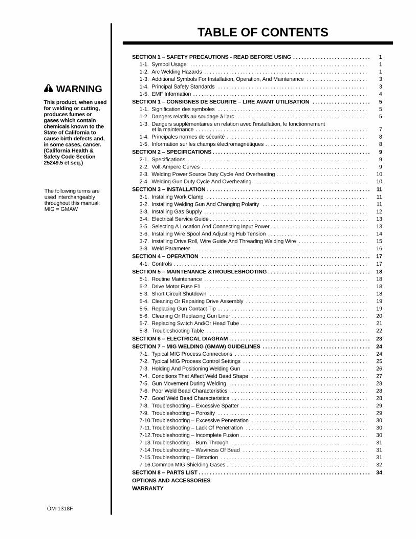
TABLE OF CONTENTS
SECTION 1 – SAFETY PRECAUTIONS - READ BEFORE USING 1. . . . . . . . . . . . . . . . . . . . . . . . . . . . 1-1. Symbol Usage 1. . . . . . . . . . . . . . . . . . . . . . . . . . . . . . . . . . . . . . . . . . . . . . . . . . . . . . . . . . . . . . . . 1-2. Arc Welding Hazards 1. . . . . . . . . . . . . . . . . . . . . . . . . . . . . . . . . . . . . . . . . . . . . . . . . . . . . . . . . . . 1-3. Additional Symbols For Installation, Operation, And Maintenance 3. . . . . . . . . . . . . . . . . . . . . . 1-4. Principal Safety Standards 3. . . . . . . . . . . . . . . . . . . . . . . . . . . . . . . . . . . . . . . . . . . . . . . . . . . . . . 1-5. EMF Information 4. . . . . . . . . . . . . . . . . . . . . . . . . . . . . . . . . . . . . . . . . . . . . . . . . . . . . . . . . . . . . . .
SECTION 1 – CONSIGNES DE SECURITE – LIRE AVANT UTILISATION 5. . . . . . . . . . . . . . . . . . . . . 1-1. Signification des symboles 5. . . . . . . . . . . . . . . . . . . . . . . . . . . . . . . . . . . . . . . . . . . . . . . . . . . . . . 1-2. Dangers relatifs au soudage à l’arc 5. . . . . . . . . . . . . . . . . . . . . . . . . . . . . . . . . . . . . . . . . . . . . . . 1-3. Dangers supplémentaires en relation avec l’installation, le fonctionnement
et la maintenance 7. . . . . . . . . . . . . . . . . . . . . . . . . . . . . . . . . . . . . . . . . . . . . . . . . . . . . . . . . . . . . . 1-4. Principales normes de sécurité 8. . . . . . . . . . . . . . . . . . . . . . . . . . . . . . . . . . . . . . . . . . . . . . . . . . . 1-5. Information sur les champs électromagnétiques 8. . . . . . . . . . . . . . . . . . . . . . . . . . . . . . . . . . . . .
SECTION 2 – SPECIFICATIONS 9. . . . . . . . . . . . . . . . . . . . . . . . . . . . . . . . . . . . . . . . . . . . . . . . . . . . . . . . . 2-1. Specifications 9. . . . . . . . . . . . . . . . . . . . . . . . . . . . . . . . . . . . . . . . . . . . . . . . . . . . . . . . . . . . . . . . . 2-2. Volt-Ampere Curves 9. . . . . . . . . . . . . . . . . . . . . . . . . . . . . . . . . . . . . . . . . . . . . . . . . . . . . . . . . . . . 2-3. Welding Power Source Duty Cycle And Overheating 10. . . . . . . . . . . . . . . . . . . . . . . . . . . . . . . . . 2-4. Welding Gun Duty Cycle And Overheating 10. . . . . . . . . . . . . . . . . . . . . . . . . . . . . . . . . . . . . . . . .
SECTION 3 – INSTALLATION 11. . . . . . . . . . . . . . . . . . . . . . . . . . . . . . . . . . . . . . . . . . . . . . . . . . . . . . . . . . . 3-1. Installing Work Clamp 11. . . . . . . . . . . . . . . . . . . . . . . . . . . . . . . . . . . . . . . . . . . . . . . . . . . . . . . . . . 3-2. Installing Welding Gun And Changing Polarity 11. . . . . . . . . . . . . . . . . . . . . . . . . . . . . . . . . . . . . . 3-3. Installing Gas Supply 12. . . . . . . . . . . . . . . . . . . . . . . . . . . . . . . . . . . . . . . . . . . . . . . . . . . . . . . . . . . 3-4. Electrical Service Guide 13. . . . . . . . . . . . . . . . . . . . . . . . . . . . . . . . . . . . . . . . . . . . . . . . . . . . . . . . . 3-5. Selecting A Location And Connecting Input Power 13. . . . . . . . . . . . . . . . . . . . . . . . . . . . . . . . . . . 3-6. Installing Wire Spool And Adjusting Hub Tension 14. . . . . . . . . . . . . . . . . . . . . . . . . . . . . . . . . . . . 3-7. Installing Drive Roll, Wire Guide And Threading Welding Wire 15. . . . . . . . . . . . . . . . . . . . . . . . . 3-8. Weld Parameter 16. . . . . . . . . . . . . . . . . . . . . . . . . . . . . . . . . . . . . . . . . . . . . . . . . . . . . . . . . . . . . . .
SECTION 4 – OPERATION 17. . . . . . . . . . . . . . . . . . . . . . . . . . . . . . . . . . . . . . . . . . . . . . . . . . . . . . . . . . . . . 4-1. Controls 17. . . . . . . . . . . . . . . . . . . . . . . . . . . . . . . . . . . . . . . . . . . . . . . . . . . . . . . . . . . . . . . . . . . . . .
SECTION 5 – MAINTENANCE &TROUBLESHOOTING 18. . . . . . . . . . . . . . . . . . . . . . . . . . . . . . . . . . . . . 5-1. Routine Maintenance 18. . . . . . . . . . . . . . . . . . . . . . . . . . . . . . . . . . . . . . . . . . . . . . . . . . . . . . . . . . . 5-2. Drive Motor Fuse F1 18. . . . . . . . . . . . . . . . . . . . . . . . . . . . . . . . . . . . . . . . . . . . . . . . . . . . . . . . . . . 5-3. Short Circuit Shutdown 18. . . . . . . . . . . . . . . . . . . . . . . . . . . . . . . . . . . . . . . . . . . . . . . . . . . . . . . . . 5-4. Cleaning Or Repairing Drive Assembly 19. . . . . . . . . . . . . . . . . . . . . . . . . . . . . . . . . . . . . . . . . . . . 5-5. Replacing Gun Contact Tip 19. . . . . . . . . . . . . . . . . . . . . . . . . . . . . . . . . . . . . . . . . . . . . . . . . . . . . . 5-6. Cleaning Or Replacing Gun Liner 20. . . . . . . . . . . . . . . . . . . . . . . . . . . . . . . . . . . . . . . . . . . . . . . . . 5-7. Replacing Switch And/Or Head Tube 21. . . . . . . . . . . . . . . . . . . . . . . . . . . . . . . . . . . . . . . . . . . . . . 5-8. Troubleshooting Table 22. . . . . . . . . . . . . . . . . . . . . . . . . . . . . . . . . . . . . . . . . . . . . . . . . . . . . . . . . .
SECTION 6 – ELECTRICAL DIAGRAM 23. . . . . . . . . . . . . . . . . . . . . . . . . . . . . . . . . . . . . . . . . . . . . . . . . . . SECTION 7 – MIG WELDING (GMAW) GUIDELINES 24. . . . . . . . . . . . . . . . . . . . . . . . . . . . . . . . . . . . . . .
7-1. Typical MIG Process Connections 24. . . . . . . . . . . . . . . . . . . . . . . . . . . . . . . . . . . . . . . . . . . . . . . . 7-2. Typical MIG Process Control Settings 25. . . . . . . . . . . . . . . . . . . . . . . . . . . . . . . . . . . . . . . . . . . . . 7-3. Holding And Positioning Welding Gun 26. . . . . . . . . . . . . . . . . . . . . . . . . . . . . . . . . . . . . . . . . . . . . 7-4. Conditions That Affect Weld Bead Shape 27. . . . . . . . . . . . . . . . . . . . . . . . . . . . . . . . . . . . . . . . . . 7-5. Gun Movement During Welding 28. . . . . . . . . . . . . . . . . . . . . . . . . . . . . . . . . . . . . . . . . . . . . . . . . . 7-6. Poor Weld Bead Characteristics 28. . . . . . . . . . . . . . . . . . . . . . . . . . . . . . . . . . . . . . . . . . . . . . . . . . 7-7. Good Weld Bead Characteristics 28. . . . . . . . . . . . . . . . . . . . . . . . . . . . . . . . . . . . . . . . . . . . . . . . . 7-8. Troubleshooting – Excessive Spatter 29. . . . . . . . . . . . . . . . . . . . . . . . . . . . . . . . . . . . . . . . . . . . . . 7-9. Troubleshooting – Porosity 29. . . . . . . . . . . . . . . . . . . . . . . . . . . . . . . . . . . . . . . . . . . . . . . . . . . . . . 7-10.Troubleshooting – Excessive Penetration 30. . . . . . . . . . . . . . . . . . . . . . . . . . . . . . . . . . . . . . . . . . 7-11.Troubleshooting – Lack Of Penetration 30. . . . . . . . . . . . . . . . . . . . . . . . . . . . . . . . . . . . . . . . . . . . 7-12.Troubleshooting – Incomplete Fusion 30. . . . . . . . . . . . . . . . . . . . . . . . . . . . . . . . . . . . . . . . . . . . . . 7-13.Troubleshooting – Burn-Through 31. . . . . . . . . . . . . . . . . . . . . . . . . . . . . . . . . . . . . . . . . . . . . . . . . 7-14.Troubleshooting – Waviness Of Bead 31. . . . . . . . . . . . . . . . . . . . . . . . . . . . . . . . . . . . . . . . . . . . . 7-15.Troubleshooting – Distortion 31. . . . . . . . . . . . . . . . . . . . . . . . . . . . . . . . . . . . . . . . . . . . . . . . . . . . . 7-16.Common MIG Shielding Gases 32. . . . . . . . . . . . . . . . . . . . . . . . . . . . . . . . . . . . . . . . . . . . . . . . . . .
SECTION 8 – PARTS LIST 34. . . . . . . . . . . . . . . . . . . . . . . . . . . . . . . . . . . . . . . . . . . . . . . . . . . . . . . . . . . . . . OPTIONS AND ACCESSORIESWARRANTY
WARNINGThis product, when usedfor welding or cutting,produces fumes orgases which containchemicals known to theState of California tocause birth defects and,in some cases, cancer.(California Health &Safety Code Section25249.5 et seq.)
OM-1318F


OM-1318 Page 1
SECTION 1 – SAFETY PRECAUTIONS - READ BEFORE USINGsom _nd_4/98
1-1. Symbol Usage
Means Warning! Watch Out! There are possible hazardswith this procedure! The possible hazards are shown inthe adjoining symbols.
� Marks a special safety message.
� Means “Note”; not safety related.
This group of symbols means Warning! Watch Out! possibleELECTRIC SHOCK, MOVING PARTS, and HOT PARTS hazards.Consult symbols and related instructions below for necessary actionsto avoid the hazards.
1-2. Arc Welding Hazards
� The symbols shown below are used throughout this manual tocall attention to and identify possible hazards. When you seethe symbol, watch out, and follow the related instructions toavoid the hazard. The safety information given below is onlya summary of the more complete safety information found inthe Safety Standards listed in Section 1-4. Read and follow allSafety Standards.
� Only qualified persons should install, operate, maintain, andrepair this unit.
� During operation, keep everybody, especially children, away.
ELECTRIC SHOCK can kill.
Touching live electrical parts can cause fatal shocksor severe burns. The electrode and work circuit iselectrically live whenever the output is on. The inputpower circuit and machine internal circuits are also
live when power is on. In semiautomatic or automatic wire welding, thewire, wire reel, drive roll housing, and all metal parts touching thewelding wire are electrically live. Incorrectly installed or improperlygrounded equipment is a hazard.
� Do not touch live electrical parts.
� Wear dry, hole-free insulating gloves and body protection.
� Insulate yourself from work and ground using dry insulating matsor covers big enough to prevent any physical contact with the workor ground.
� Do not use AC output in damp areas, if movement is confined, or ifthere is a danger of falling.
� Use AC output ONLY if required for the welding process.
� If AC output is required, use remote output control if present onunit.
� Disconnect input power or stop engine before installing orservicing this equipment. Lockout/tagout input power according toOSHA 29 CFR 1910.147 (see Safety Standards).
� Properly install and ground this equipment according to itsOwner’s Manual and national, state, and local codes.
� Always verify the supply ground – check and be sure that inputpower cord ground wire is properly connected to ground terminal indisconnect box or that cord plug is connected to a properlygrounded receptacle outlet.
� When making input connections, attach proper grounding conduc-tor first – double-check connections.
� Frequently inspect input power cord for damage or bare wiring –replace cord immediately if damaged – bare wiring can kill.
� Turn off all equipment when not in use.
� Do not use worn, damaged, undersized, or poorly spliced cables.
� Do not drape cables over your body.
� If earth grounding of the workpiece is required, ground it directlywith a separate cable.
� Do not touch electrode if you are in contact with the work, ground,or another electrode from a different machine.
� Use only well-maintained equipment. Repair or replace damagedparts at once. Maintain unit according to manual.
� Wear a safety harness if working above floor level.
� Keep all panels and covers securely in place.
� Clamp work cable with good metal-to-metal contact to workpieceor worktable as near the weld as practical.
� Insulate work clamp when not connected to workpiece to preventcontact with any metal object.
� Do not connect more than one electrode or work cable to anysingle weld output terminal.
SIGNIFICANT DC VOLTAGE exists after removal ofinput power on inverters.� Turn Off inverter, disconnect input power, and discharge input
capacitors according to instructions in Maintenance Sectionbefore touching any parts.
Welding produces fumes and gases. Breathingthese fumes and gases can be hazardous to yourhealth.
FUMES AND GASES can be hazardous.
� Keep your head out of the fumes. Do not breathe the fumes.
� If inside, ventilate the area and/or use exhaust at the arc to removewelding fumes and gases.
� If ventilation is poor, use an approved air-supplied respirator.
� Read the Material Safety Data Sheets (MSDSs) and themanufacturer’s instructions for metals, consumables, coatings,cleaners, and degreasers.
� Work in a confined space only if it is well ventilated, or whilewearing an air-supplied respirator. Always have a trained watch-person nearby. Welding fumes and gases can displace air andlower the oxygen level causing injury or death. Be sure the breath-ing air is safe.
� Do not weld in locations near degreasing, cleaning, or spraying op-erations. The heat and rays of the arc can react with vapors to formhighly toxic and irritating gases.
� Do not weld on coated metals, such as galvanized, lead, orcadmium plated steel, unless the coating is removed from the weldarea, the area is well ventilated, and if necessary, while wearing anair-supplied respirator. The coatings and any metals containingthese elements can give off toxic fumes if welded.
OM-1318 Page 2
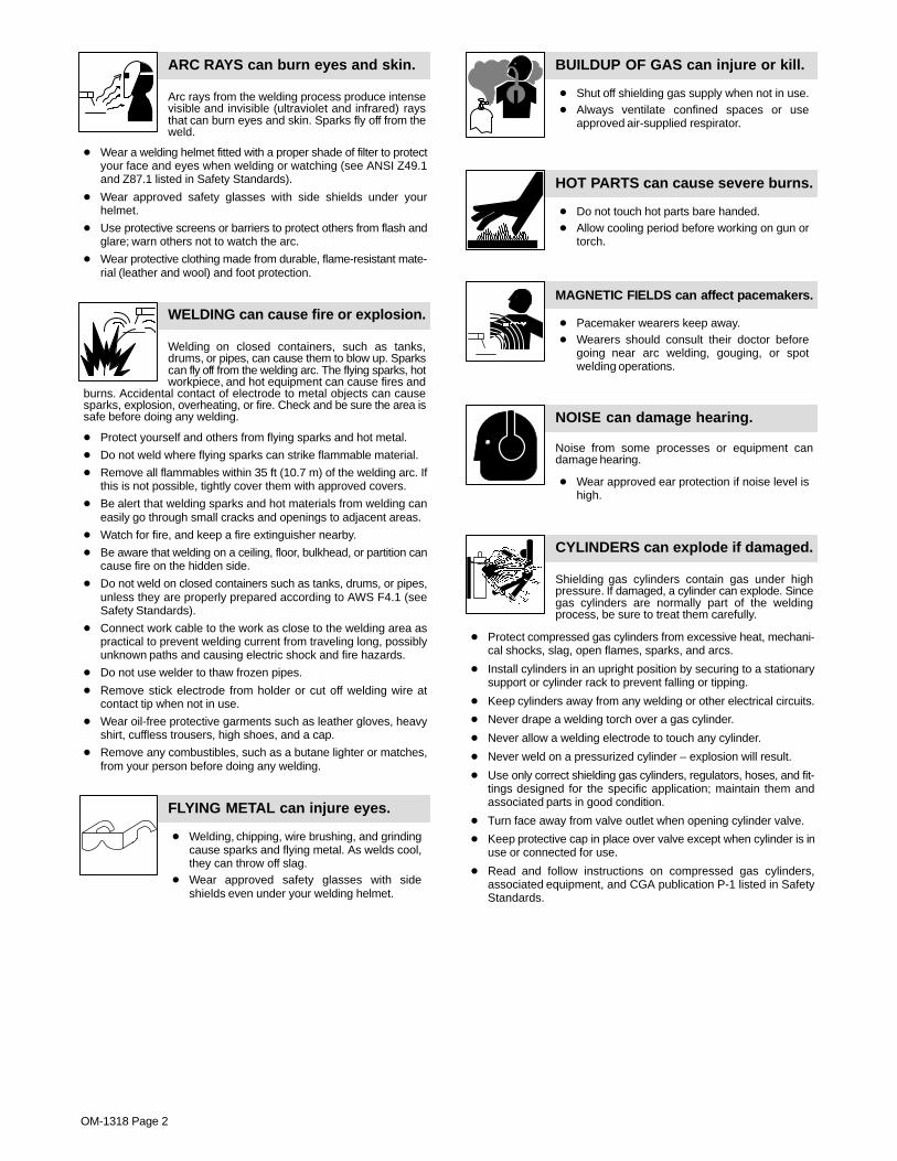
Arc rays from the welding process produce intensevisible and invisible (ultraviolet and infrared) raysthat can burn eyes and skin. Sparks fly off from theweld.
ARC RAYS can burn eyes and skin.
� Wear a welding helmet fitted with a proper shade of filter to protectyour face and eyes when welding or watching (see ANSI Z49.1and Z87.1 listed in Safety Standards).
� Wear approved safety glasses with side shields under yourhelmet.
� Use protective screens or barriers to protect others from flash andglare; warn others not to watch the arc.
� Wear protective clothing made from durable, flame-resistant mate-rial (leather and wool) and foot protection.
Welding on closed containers, such as tanks,drums, or pipes, can cause them to blow up. Sparkscan fly off from the welding arc. The flying sparks, hotworkpiece, and hot equipment can cause fires and
burns. Accidental contact of electrode to metal objects can causesparks, explosion, overheating, or fire. Check and be sure the area issafe before doing any welding.
WELDING can cause fire or explosion.
� Protect yourself and others from flying sparks and hot metal.
� Do not weld where flying sparks can strike flammable material.
� Remove all flammables within 35 ft (10.7 m) of the welding arc. Ifthis is not possible, tightly cover them with approved covers.
� Be alert that welding sparks and hot materials from welding caneasily go through small cracks and openings to adjacent areas.
� Watch for fire, and keep a fire extinguisher nearby.
� Be aware that welding on a ceiling, floor, bulkhead, or partition cancause fire on the hidden side.
� Do not weld on closed containers such as tanks, drums, or pipes,unless they are properly prepared according to AWS F4.1 (seeSafety Standards).
� Connect work cable to the work as close to the welding area aspractical to prevent welding current from traveling long, possiblyunknown paths and causing electric shock and fire hazards.
� Do not use welder to thaw frozen pipes.
� Remove stick electrode from holder or cut off welding wire atcontact tip when not in use.
� Wear oil-free protective garments such as leather gloves, heavyshirt, cuffless trousers, high shoes, and a cap.
� Remove any combustibles, such as a butane lighter or matches,from your person before doing any welding.
FLYING METAL can injure eyes.
� Welding, chipping, wire brushing, and grindingcause sparks and flying metal. As welds cool,they can throw off slag.
� Wear approved safety glasses with sideshields even under your welding helmet.
BUILDUP OF GAS can injure or kill.
� Shut off shielding gas supply when not in use.� Always ventilate confined spaces or use
approved air-supplied respirator.
HOT PARTS can cause severe burns.
� Do not touch hot parts bare handed.� Allow cooling period before working on gun or
torch.
MAGNETIC FIELDS can affect pacemakers.
� Pacemaker wearers keep away.� Wearers should consult their doctor before
going near arc welding, gouging, or spotwelding operations.
NOISE can damage hearing.
Noise from some processes or equipment candamage hearing.
� Wear approved ear protection if noise level ishigh.
Shielding gas cylinders contain gas under highpressure. If damaged, a cylinder can explode. Sincegas cylinders are normally part of the weldingprocess, be sure to treat them carefully.
CYLINDERS can explode if damaged.
� Protect compressed gas cylinders from excessive heat, mechani-cal shocks, slag, open flames, sparks, and arcs.
� Install cylinders in an upright position by securing to a stationarysupport or cylinder rack to prevent falling or tipping.
� Keep cylinders away from any welding or other electrical circuits.
� Never drape a welding torch over a gas cylinder.
� Never allow a welding electrode to touch any cylinder.
� Never weld on a pressurized cylinder – explosion will result.
� Use only correct shielding gas cylinders, regulators, hoses, and fit-tings designed for the specific application; maintain them andassociated parts in good condition.
� Turn face away from valve outlet when opening cylinder valve.
� Keep protective cap in place over valve except when cylinder is inuse or connected for use.
� Read and follow instructions on compressed gas cylinders,associated equipment, and CGA publication P-1 listed in SafetyStandards.

OM-1318 Page 3
1-3. Additional Symbols For Installation, Operation, And Maintenance
FIRE OR EXPLOSION hazard.
� Do not install or place unit on, over, or nearcombustible surfaces.
� Do not install unit near flammables.
� Do not overload building wiring – be sure power supply system isproperly sized, rated, and protected to handle this unit.
FALLING UNIT can cause injury.
� Use lifting eye to lift unit only, NOT runninggear, gas cylinders, or any other accessories.
� Use equipment of adequate capacity to lift andsupport unit.
� If using lift forks to move unit, be sure forks arelong enough to extend beyond opposite side ofunit.
OVERUSE can cause OVERHEATING
� Allow cooling period; follow rated duty cycle.� Reduce current or reduce duty cycle before
starting to weld again.� Do not block or filter airflow to unit.
STATIC (ESD) can damage PC boards.
� Put on grounded wrist strap BEFORE handlingboards or parts.
� Use proper static-proof bags and boxes tostore, move, or ship PC boards.
MOVING PARTS can cause injury.
� Keep away from moving parts.� Keep away from pinch points such as drive
rolls.
WELDING WIRE can cause injury.
� Do not press gun trigger until instructed to doso.
� Do not point gun toward any part of the body,other people, or any metal when threadingwelding wire.
MOVING PARTS can cause injury.
� Keep away from moving parts such as fans.� Keep all doors, panels, covers, and guards
closed and securely in place.
H.F. RADIATION can cause interference.
� High-frequency (H.F.) can interfere with radionavigation, safety services, computers, andcommunications equipment.
� Have only qualified persons familiar withelectronic equipment perform this installation.
� The user is responsible for having a qualified electrician prompt-ly correct any interference problem resulting from the installa-tion.
� If notified by the FCC about interference, stop using theequipment at once.
� Have the installation regularly checked and maintained.
� Keep high-frequency source doors and panels tightly shut, keepspark gaps at correct setting, and use grounding and shielding tominimize the possibility of interference.
ARC WELDING can cause interference.
� Electromagnetic energy can interfere withsensitive electronic equipment such ascomputers and computer-driven equipmentsuch as robots.
� Be sure all equipment in the welding area iselectromagnetically compatible.
� To reduce possible interference, keep weld cables as short aspossible, close together, and down low, such as on the floor.
� Locate welding operation 100 meters from any sensitive elec-tronic equipment.
� Be sure this welding machine is installed and groundedaccording to this manual.
� If interference still occurs, the user must take extra measuressuch as moving the welding machine, using shielded cables,using line filters, or shielding the work area.
1-4. Principal Safety Standards
Safety in Welding and Cutting, ANSI Standard Z49.1, from AmericanWelding Society, 550 N.W. LeJeune Rd, Miami FL 33126Safety and Health Standards, OSHA 29 CFR 1910, from Superinten-dent of Documents, U.S. Government Printing Office, Washington, D.C.20402.Recommended Safe Practices for the Preparation for Welding and Cut-ting of Containers That Have Held Hazardous Substances, AmericanWelding Society Standard AWS F4.1, from American Welding Society,550 N.W. LeJeune Rd, Miami, FL 33126National Electrical Code, NFPA Standard 70, from National Fire Protec-tion Association, Batterymarch Park, Quincy, MA 02269.
Safe Handling of Compressed Gases in Cylinders, CGA Pamphlet P-1,from Compressed Gas Association, 1235 Jefferson Davis Highway,Suite 501, Arlington, VA 22202.Code for Safety in Welding and Cutting, CSA Standard W117.2, fromCanadian Standards Association, Standards Sales, 178 RexdaleBoulevard, Rexdale, Ontario, Canada M9W 1R3.Safe Practices For Occupation And Educational Eye And FaceProtection, ANSI Standard Z87.1, from American National StandardsInstitute, 1430 Broadway, New York, NY 10018.Cutting And Welding Processes, NFPA Standard 51B, from NationalFire Protection Association, Batterymarch Park, Quincy, MA 02269.

OM-1318 Page 4
1-5. EMF Information
Considerations About Welding And The Effects Of Low FrequencyElectric And Magnetic FieldsWelding current, as it flows through welding cables, will cause electro-magnetic fields. There has been and still is some concern about suchfields. However, after examining more than 500 studies spanning 17years of research, a special blue ribbon committee of the NationalResearch Council concluded that: “The body of evidence, in thecommittee’s judgment, has not demonstrated that exposure to power-frequency electric and magnetic fields is a human-health hazard.”However, studies are still going forth and evidence continues to beexamined. Until the final conclusions of the research are reached, youmay wish to minimize your exposure to electromagnetic fields whenwelding or cutting.To reduce magnetic fields in the workplace, use the followingprocedures:
1. Keep cables close together by twisting or taping them.
2. Arrange cables to one side and away from the operator.
3. Do not coil or drape cables around your body.
4. Keep welding power source and cables as far away from opera-tor as practical.
5. Connect work clamp to workpiece as close to the weld as possi-ble.
About Pacemakers:Pacemaker wearers consult your doctor first. If cleared by your doctor,then following the above procedures is recommended.

OM-1318 Page 5
SECTION 1 – CONSIGNES DE SECURITE – LIRE AVANTUTILISATION
som _nd_fre 4/98
1-1. Signification des symboles
Signifie Mise en garde ! Soyez vigilant ! Cette procédureprésente des risques de danger ! Ceux-ci sont identifiéspar des symboles adjacents aux directives.
� Identifie un message de sécurité particulier.
� Signifie NOTA ; n’est pas relatif à la sécurité.
Ce groupe de symboles signifie Mise en garde ! Soyez vigilant ! Il y a desrisques de danger reliés aux CHOCS ÉLECTRIQUES, aux PIÈCES ENMOUVEMENT et aux PIÈCES CHAUDES. Reportez-vous aux symboleset aux directives ci-dessous afin de connaître les mesures à prendre pouréviter tout danger.
1-2. Dangers relatifs au soudage à l’arc
� Les symboles présentés ci-après sont utilisés tout au long duprésent manuel pour attirer votre attention et identifier les risquesde danger. Lorsque vous voyez un symbole, soyez vigilant etsuivez les directives mentionnées afin d’éviter tout danger. Lesconsignes de sécurité présentées ci-après ne font que résumerl’information contenue dans les normes de sécurité énuméréesà la section 1-4. Veuillez lire et respecter toutes ces normes desécurité.
� L’installation, l’utilisation, l’entretien et les réparations ne doi-vent être confiés qu’à des personnes qualifiées.
� Au cours de l’utilisation, tenir toute personne à l’écart et plus par-ticulièrement les enfants.
UN CHOC ÉLECTRIQUE peut tuer.
Un simple contact avec des pièces électriques peutprovoquer une électrocution ou des blessures graves.L’électrode et le circuit de soudage sont sous tensiondès que l’appareil est sur ON. Le circuit d’entrée et lescircuits internes de l’appareil sont également sous
tension à ce moment-là. En soudage semi-automatique ou automatique,le fil, le dévidoir, le logement des galets d’entraînement et les piècesmétalliques en contact avec le fil de soudage sont sous tension. Desmatériels mal installés ou mal mis à la terre présentent un danger.
� Ne jamais toucher les pièces électriques sous tension.� Porter des gants et des vêtements de protection secs ne comportant
pas de trous.� S’isoler de la pièce et de la terre au moyen de tapis ou d’autres
moyens isolants suffisamment grands pour empêcher le contact phy-sique éventuel avec la pièce ou la terre.
� Ne pas se servir de source électrique àcourant électrique dans les zoneshumides, dans les endroits confinés ou là où on risque de tomber.
� Se servir d’une source électrique àcourant électrique UNIQUEMENT si leprocédé de soudage le demande.
� Si l’utilisation d’une source électrique àcourant électrique s’avère néces-saire, se servir de la fonction de télécommande si l’appareil en est équipé.
� Couper l’alimentation ou arrêter le moteur avant de procéder à l’instal-lation, à la réparation ou à l’entretien de l’appareil. Déverrouillerl’alimentation selon la norme OSHA 29 CFR 1910.147 (voir normes desécurité).
� Installer et mettre à la terre correctement cet appareil conformément àson manuel d’utilisation et aux codes nationaux, provinciaux etmunicipaux.
� Toujours vérifier la terre du cordon d’alimentation – Vérifier et s’assu-rer que le fil de terre du cordon d’alimentation est bien raccordé à laborne de terre du sectionneur ou que la fiche du cordon est raccordéeà une prise correctement mise à la terre.
� En effectuant les raccordements d’entrée fixer d’abord le conducteurde mise à la terre approprié et contre-vérifier les connexions.
� Vérifier fréquemment le cordon d’alimentation pour voir s’il n’est pasendommagé ou dénudé – remplacer le cordon immédiatement s’il estendommagé – un câble dénudé peut provoquer une électrocution.
� Mettre l’appareil hors tension quand on ne l’utilise pas.� Ne pas utiliser des câbles usés, endommagés, de grosseur insuffi-
sante ou mal épissés.� Ne pas enrouler les câbles autour du corps.� Si la pièce soudée doit être mise à la terre, le faire directement avec un
câble distinct.� Ne pas toucher l’électrode quand on est en contact avec la pièce, la
terre ou une électrode provenant d’une autre machine.
� N’utiliser qu’un matériel en bon état. Réparer ou remplacer sur-le-champ les pièces endommagées. Entretenir l’appareil conformémentà ce manuel.
� Porter un harnais de sécurité quand on travaille en hauteur.
� Maintenir solidement en place tous les panneaux et capots.
� Fixer le câble de retour de façon à obtenir un bon contact métal-métalavec la pièce à souder ou la table de travail, le plus près possible de lasoudure.
� Isoler la pince de masse quand pas mis à la pièce pour éviter le contactavec tout objet métallique.
Il y a DU COURANT CONTINU IMPORTANT dans lesconvertisseurs après la suppression de l’alimenta-tion électrique.� Arrêter les convertisseurs, débrancher le courant électrique, et dé-
charger les condensateurs d’alimentation selon les instructionsindiquées dans la partie entretien avant de toucher les pièces.
Le soudage génère des fumées et des gaz. Leurinhalation peut être dangereux pour votre santé.
� Eloigner votre tête des fumées. Ne pas respirerles fumées.
� A l’intérieur, ventiler la zone et/ou utiliser un échappement au niveaude l’arc pour l’évacuation des fumées et des gaz de soudage.
� Si la ventilation est insuffisante, utiliser un respirateur à alimenta-tion d’air homologué.
� Lire les spécifications de sécurité des matériaux (MSDSs) et lesinstructions du fabricant concernant les métaux, les consomma-bles, les revêtements, les nettoyants et les dégraisseurs.
� Travailler dans un espace fermé seulement s’il est bien ventilé ou enportant un respirateur à alimentation d’air. Demander toujours à unsurveillant dûment formé de se tenir à proximité. Des fumées et desgaz de soudage peuvent déplacer l’air et abaisser le niveau d’oxy-gène provoquant des blessures ou des accidents mortels. S’assu-rer que l’air de respiration ne présente aucun danger.
� Ne pas souder dans des endroits situés à proximité d’opérations dedégraissage, de nettoyage ou de pulvérisation. La chaleur et lesrayons de l’arc peuvent réagir en présence de vapeurs et former desgaz hautement toxiques et irritants.
� Ne pas souder des métaux munis d’un revêtement, tels que l’aciergalvanisé, plaqué en plomb ou au cadmium à moins que le revête-ment n’ait été enlevé dans la zone de soudure, que l’endroit soit bienventilé, et si nécessaire, en portant un respirateur à alimentationd’air. Les revêtements et tous les métaux renfermant ces élémentspeuvent dégager des fumées toxiques en cas de soudage.
LES FUMÉES ET LES GAZ peuventêtre dangereux.

OM-1318 Page 6
Le rayonnement de l’arc du procédé de soudagegénère des rayons visibles et invisibles intenses(ultraviolets et infrarouges) susceptibles de provoquer
des brûlures dans les yeux et sur la peau. Des étincelles sont projetéespendant le soudage.
LES RAYONS DE L’ARC peuvent pro-voquer des brûlures dans les yeux etsur la peau.
� Porter un casque de soudage muni d’un écran de filtre approprié pourprotéger votre visage et vos yeux pendant le soudage ou pour regar-der (voir ANSI Z49.1 et Z87.1 énuméré dans les normes de sécurité).
� Porter des protections approuvés pour les oreilles si le niveau sondre esttrop élevé.
� Utiliser des écrans ou des barrières pour protéger des tiers de l’éclairet de l’éblouissement; demander aux autres personnes de ne pas re-garder l’arc.
� Porter des vêtements de protection constitué dans une matière dura-ble, résistant au feu (cuir ou laine) et une protection des pieds.
Le soudage effectué sur des conteneurs fermés telsque des réservoirs, tambours ou des conduites peutprovoquer leur éclatement. Des étincelles peuvent êtreprojetées de l’arc de soudure. La projection d’étincel-
les, des pièces chaudes et des équipements chauds peut provoquer desincendies et des brûlures. Le contact accidentel de l’électrode avec desobjets métalliques peut provoquer des étincelles, une explosion, unsurchauffement ou un incendie. Avant de commencer le soudage, vérifieret s’assurer que l’endroit ne présente pas de danger.
LE SOUDAGE peut provoquer unincendie ou une explosion.
� Se protéger et d’autres personnes de la projection d’étincelles et demétal chaud.
� Ne pas souder dans un endroit là où des étincelles peuvent tomber surdes substances inflammables.
� Déplacer toutes les substances inflammables à une distance de 10,7m de l’arc de soudage. En cas d’impossibilité les recouvrir soigneuse-ment avec des protections homologués.
� Des étincelles et des matériaux chauds du soudage peuvent facile-ment passer dans d’autres zones en traversant de petites fissures etdes ouvertures.
� Surveiller tout déclenchement d’incendie et tenir un extincteur à proxi-mité.
� Le soudage effectué sur un plafond, plancher, paroi ou séparationpeut déclencher un incendie de l’autre côté.
� Ne pas effectuer le soudage sur des conteneurs fermés tels que desréservoirs, tambours, ou conduites, à moins qu’ils n’aient été prépa-rés correctement conformément à AWS F4.1 (voir les normes desécurité).
� Brancher le câble sur la pièce le plus près possible de la zone de sou-dage pour éviter le transport du courant sur une longue distance pardes chemins inconnus éventuels en provoquant des risques d’élec-trocution et d’incendie.
� Ne pas utiliser le poste de soudage pour dégeler des conduites ge-lées.
� En cas de non utilisation, enlever la baguette d’électrode du porte-électrode ou couper le fil à la pointe de contact.
� Porter des vêtements de protection dépourvus d’huile tels que desgants en cuir, une chemise en matériau lourd, des pantalons sans re-vers, des chaussures hautes et un couvre chef.
� Avant de souder, retirer toute substance combustible de vos pochestelles qu’un allumeur au butane ou des allumettes.
DES PARTICULES VOLANTESpeuvent blesser les yeux.
� Le soudage, l’écaillement, le passage de la pièceà la brosse en fil de fer, et le meulage génèrentdes étincelles et des particules métalliques vo-
lantes. Pendant la période de refroidissement des soudures, elles ris-quent de projeter du laitier.� Porter des lunettes de sécurité avec écrans latéraux ou un écran facial.
LES ACCUMULATIONS DE GAZ ris-quent de provoquer des blessures oumême la mort.
� Fermer l’alimentation du gaz protecteur en cas denon utilisation.
� Veiller toujours à bien aérer les espaces confinés ou se servir d’un respi-rateur d’adduction d’air homologué.
DES PIÈCES CHAUDES peuvent pro-voquer des brûlures graves.
� Ne pas toucher des parties chaudes à mains nues� Prévoir une période de refroidissement avant
d’utiliser le pistolet ou la torche.
LES CHAMPS MAGNÉTIQUES peuventaffecter les stimulateurs cardiaques.
� Porteurs de stimulateur cardiaque, restez à distance.� Les porteurs d’un stimulateur cardiaque doivent
d’abord consulter leur médecin avant de s’approcherdes opérations de soudage à l’arc, de gougeage oude soudage par points.
LE BRUIT peut affecter l’ouïe.
Le bruit des processus et des équipements peut affecterl’ouïe.
� Porter des protections approuvés pour les oreilles sile niveau sondre est trop élevé.
Des bouteilles de gaz protecteur contiennent du gazsous haute pression. Si une bouteille est endomma-gée, elle peut exploser. Du fait que les bouteilles de gazfont normalement partie du procédé de soudage, les
manipuler avec précaution.
� Protéger les bouteilles de gaz comprimé d’une chaleur excessive,des chocs mécaniques, du laitier, des flammes ouvertes, des étin-celles et des arcs.
� Placer les bouteilles debout en les fixant dans un support stationnai-re ou dans un porte-bouteilles pour les empêcher de tomber ou dese renverser.
� Tenir les bouteilles éloignées des circuits de soudage ou autres cir-cuits électriques.
� Ne jamais placer une torche de soudage sur une bouteille à gaz.� Une électrode de soudage ne doit jamais entrer en contact avec une
bouteille.� Ne jamais souder une bouteille pressurisée – risque d’explosion.� Utiliser seulement des bouteilles de gaz protecteur, régulateurs,
tuyaux et raccords convenables pour cette application spécifique;les maintenir ainsi que les éléments associés en bon état.
� Ne pas tenir la tête en face de la sortie en ouvrant la soupape de labouteille.
� Maintenir le chapeau de protection sur la soupape, sauf en cas d’uti-lisation ou de branchement de la bouteille.
� Lire et suivre les instructions concernant les bouteilles de gaz com-primé, les équipements associés et les publications P-1 CGA énu-mérées dans les normes de sécurité.
Si des BOUTEILLES sont endomma-gées, elles pourront exploser.

OM-1318 Page 7
1-3. Dangers supplémentaires en relation avec l’installation, le fonctionnementet la maintenance
Risque D’INCENDIE OUD’EXPLOSION.
� Ne pas placer l’appareil sur, au-dessus ou à proxi-mité de surfaces infllammables.
� Ne pas installer l’appareil à proximité de produits inflammables� Ne pas surcharger l’installation électrique – s”assurer que l’alimen-
tation est correctement dimensionné et protégé avant de mettrel’appareil en service.
LA CHUTE DE L’APPAREIL peutblesser.
� Utiliser l’anneau de levage uniquement pour sou-lever l’appareil, NON PAS les chariot, les bouteil-les de gaz ou tout autre accessoire.
� Utiliser un engin d’une capacité appropriée poursoulever l’appareil.
� En utilisant des fourches de levage pour déplacer l’unité, s’assurerque les fourches sont suffisamment longues pour dépasser du côtéopposé de l’appareil.
L’EMPLOI EXCESSIF peutSURCHAUFFER L’ÉQUIPEMENT.
� Prévoir une période de refroidissement, respec-ter le cycle opératoire nominal.
� Réduire le courant ou le cycle opératoire avant derecommancer le soudage.
� Ne pas obstruer les passages d’air du poste.
LES CHARGES ÉLECTROSTATI-QUES peuvent endommager les cir-cuits imprimés.
� Établir la connexion avec la barrette de terreavant de manipuler des cartes ou des pièces.
� Utiliser des pochettes et des boîtes antistatiquespour stocker, déplacer ou expédier des cartes decircuits imprimes.
DES ORGANES MOBILES peuventprovoquer des blessures.
� Ne pas s’approcher des organes mobiles.� Ne pas s’approcher des points de coincement
tels que des rouleaux de commande.
LES FILS DE SOUDAGE peuvent pro-voquer des blessures.
� Ne pas appuyer sur la gachette avant d’en avoirreçu l’instruction.
� Ne pas diriger le pistolet vers soi, d’autres person-nes ou toute pièce mécanique en engageant le filde soudage.
DES ORGANES MOBILES peuventprovoquer des blessures.
� Rester à l’écart des organes mobiles comme leventilateur.
� Maintenir fermés et fixement en place les portes,panneaux, recouvrements et dispositifs deprotection.
LE RAYONNEMENT HAUTE FRÉ-QUENCE (H.F.) risque de provoquerdes interférences.
� Le rayonnement haute frequence peut provoquerdes interférences avec les équipements de ra-dio–navigation et de communication, les servicesde sécurité et les ordinateurs.
� Demander seulement à des personnes qualifiées familiariséesavec des équipements électroniques de faire fonctionner l’installa-tion.
� L’utilisateur est tenu de faire corriger rapidement par un électricienqualifié les interférences résultant de l’installation.
� Si le FCC signale des interférences, arrêter immédiatement l’appa-reil.
� Effectuer régulièrement le contrôle et l’entretien de l’installation.� Maintenir soigneusement fermés les portes et les panneaux des
sources de haute fréquence, maintenir les éclateurs à une distancecorrecte et utiliser une terre et et un blindage pour réduire les interfé-rences éventuelles.
LE SOUDAGE À L’ARC risque deprovoquer des interférences.
� L’énergie électromagnétique risque de provoquerdes interférences pour l’équipement électroniquesensible tel que les ordinateurs et l’équipementcommandé par ordinateur tel que les robots.
� Veiller à ce que tout l’équipement de la zone de soudage soit com-patible électromagnétiquement.
� Pour réduire la possibilité d’interférence, maintenir les câbles desoudage aussi courts que possible, les grouper, et les poser aussibas que possible (ex. par terre).
� Veiller à souder à une distance de 100 mètres de tout équipementélectronique sensible.
� Veiller à ce que ce poste de soudage soit posé et mis à la terreconformément à ce mode d’emploi.
� En cas d’interférences après avoir pris les mesures précédentes, ilincombe à l’utilisateur de prendre des mesures supplémentaires tel-les que le déplacement du poste, l’utilisation de câbles blindés, l’uti-lisation de filtres de ligne ou la pose de protecteurs dans la zone detravail.
LES CHAMPS MAGNÉTIQUES peuventaffecter les stimulateurs cardiaques.
� Porteurs de stimulateur cardiaque, restez à dis-tance.
� Les porteurs d’un stimulateur cardiaque doiventd’abord consulter leur médecin avant de s’appro-cher des opérations de soudage à l’arc, de gou-geage ou de soudage par points.

OM-1318 Page 8
1-4. Principales normes de sécurité
Safety in Welding and Cutting, norme ANSI Z49.1, de l’American Wel-ding Society, 550 N.W. Lejeune Rd, Miami FL 33126
Safety and Health Sandards, OSHA 29 CFR 1910, du Superintendentof Documents, U.S. Government Printing Office, Washington, D.C.20402.
Recommended Safe Practice for the Preparation for Welding and Cut-ting of Containers That Have Held Hazardous Substances, norme AWSF4.1, de l’American Welding Society, 550 N.W. Lejeune Rd, Miami FL33126
National Electrical Code, NFPA Standard 70, de la National Fire Protec-tion Association, Batterymarch Park, Quincy, MA 02269.
Safe Handling of Compressed Gases in Cylinders, CGA Pamphlet P-1,de la Compressed Gas Association, 1235 Jefferson Davis Highway,Suite 501, Arlington, VA 22202.
Règles de sécurité en soudage, coupage et procédés connexes, normeCSA W117.2, de l’Association canadienne de normalisation, vente denormes, 178 Rexdale Boulevard, Rexdale (Ontario) Canada M9W 1R3.
Safe Practices For Occupation And Educational Eye And Face Protec-tion, norme ANSI Z87.1, de l’American National Standards Institute,1430 Broadway, New York, NY 10018.
Cutting and Welding Processes, norme NFPA 51B, de la National FireProtection Association, Batterymarch Park, Quincy, MA 02269.
1-5. Information sur les champs électromagnétiques
Données sur le soudage électrique et sur les effets, pour l’organisme,des champs magnétiques basse fréquence
Le courant de soudage, pendant son passage dans les câbles de sou-dage, causera des champs électromagnétiques. Il y a eu et il y a encoreun certain souci à propos de tels champs. Cependant, après avoir ex-aminé plus de 500 études qui ont été faites pendant une période derecherche de 17 ans, un comité spécial ruban bleu du National Re-search Council a conclu: “L’accumulation de preuves, suivant lejugement du comité, n’a pas démontré que l’exposition aux champsmagnétiques et champs électriques à haute fréquence représente unrisque à la santé humaine”. Toutefois, des études sont toujours en courset les preuves continuent à être examinées. En attendant que les con-clusions finales de la recherche soient établies, il vous seraitsouhaitable de réduire votre exposition aux champs électromagnéti-ques pendant le soudage ou le coupage.
Afin de réduire les champs électromagnétiques dans l’environnementde travail, respecter les consignes suivantes :
1 Garder les câbles ensembles en les torsadant ou en lesattachant avec du ruban adhésif.
2 Mettre tous les câbles du côté opposé de l’opérateur.
3 Ne pas courber pas et ne pas entourer pas les câbles autour devotre corps.
4 Garder le poste de soudage et les câbles le plus loin possible devous.
5 Relier la pince de masse le plus près possible de la zone desoudure.
Consignes relatives aux stimulateurs cardiaques :
Les personnes qui portent un stimulateur cardiaque doivent avant toutconsulter leur docteur. Si vous êtes déclaré apte par votre docteur, il estalors recommandé de respecter les consignes ci–dessus.
OM-1318 Page 9
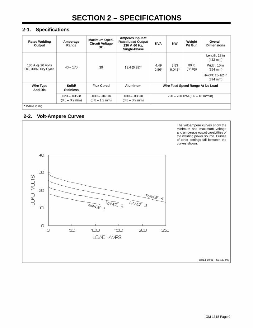
SECTION 2 – SPECIFICATIONS2-1. Specifications
Rated WeldingOutput
AmperageRange
Maximum Open-Circuit Voltage
DC
Amperes Input atRated Load Output
230 V, 60 Hz,Single-Phase
KVA KWWeightW/ Gun
Overall Dimensions
130 A @ 20 VoltsDC, 30% Duty Cycle 40 – 170 30 19.4 (0.28)*
4.490.86*
3.830.043*
80 lb(36 kg)
Length: 17 in(432 mm)
Width: 10 in(254 mm)
Height: 15-1/2 in(394 mm)
Wire TypeAnd Dia
Solid/Stainless
Flux Cored Aluminum Wire Feed Speed Range At No Load
.023 – .035 in(0.6 – 0.9 mm)
.030 – .045 in(0.8 – 1.2 mm)
.030 – .035 in(0.8 – 0.9 mm)
220 – 700 IPM (5.6 – 18 m/min)
* While idling
2-2. Volt-Ampere Curves
The volt-ampere curves show theminimum and maximum voltageand amperage output capabilities ofthe welding power source. Curvesof other settings fall between thecurves shown.
ssb1.1 10/91 – SB-187 997
OM-1318 Page 10
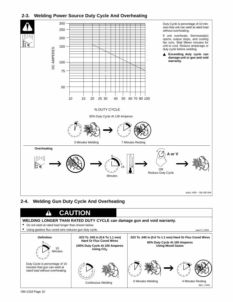
2-3. Welding Power Source Duty Cycle And Overheating
Duty Cycle is percentage of 10 min-utes that unit can weld at rated loadwithout overheating.
If unit overheats, thermostat(s)opens, output stops, and coolingfan runs. Wait fifteen minutes forunit to cool. Reduce amperage orduty cycle before welding.
� Exceeding duty cycle candamage unit or gun and voidwarranty.
30% Duty Cycle At 130 Amperes
Overheating
0
15
A or V
ORReduce Duty Cycle
Minutes
duty1 4/95 – SB-180 844
300
250
200
150
100
75
50
10 15 20 25 30 40 50 60 70 80 100
DC
AM
PE
RE
S
% DUTY CYCLE
3 Minutes Welding 7 Minutes Resting
2-4. Welding Gun Duty Cycle And Overheating
CAUTIONWELDING LONGER THAN RATED DUTY CYCLE can damage gun and void warranty.• Do not weld at rated load longer than shown below.
• Using gasless flux cored wire reduces gun duty cycle. warn7.1 8/93
Duty Cycle is percentage of 10minutes that gun can weld atrated load without overheating.
Continuous WeldingSB1.1 8/93
0
10Minutes
Definition .023 To .045 in (0.6 To 1.1 mm)Hard Or Flux Cored Wires
100% Duty Cycle At 100 AmperesUsing CO2
.023 To .045 in (0.6 To 1.1 mm) Hard Or Flux Cored Wires
60% Duty Cycle At 100 AmperesUsing Mixed Gases
6 Minutes Welding 4 Minutes Resting
OM-1318 Page 11
SECTION 3 – INSTALLATION
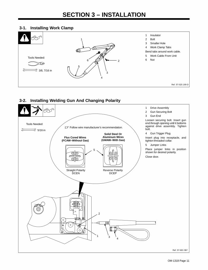
3-1. Installing Work Clamp
1 Insulator
2 Bolt
3 Smaller Hole
4 Work Clamp Tabs
Bend tabs around work cable.
5 Work Cable From Unit6 Nut
1
2
3
4
5
6
Ref. ST-025 190-D
Tools Needed:
3/8, 7/16 in
3-2. Installing Welding Gun And Changing Polarity
1 Drive Assembly
2 Gun Securing Bolt
3 Gun End
Loosen securing bolt. Insert gunend through opening until it bottomsagainst drive assembly. Tightenbolt.
4 Gun Trigger Plug
Insert plug into receptacle, andtighten threaded collar.
5 Jumper Links
Place jumper links in positionshown for desired polarity.
Close door.
Tools Needed:
2
1 34
Ref. ST-801 987
5/16 in
Straight PolarityDCEN
Reverse PolarityDCEP
Flux Cored Wires(FCAW–Without Gas)
Solid Steel OrAluminum Wires
(GMAW–With Gas)
� Follow wire manufacturer’s recommendation.
5
OM-1318 Page 12
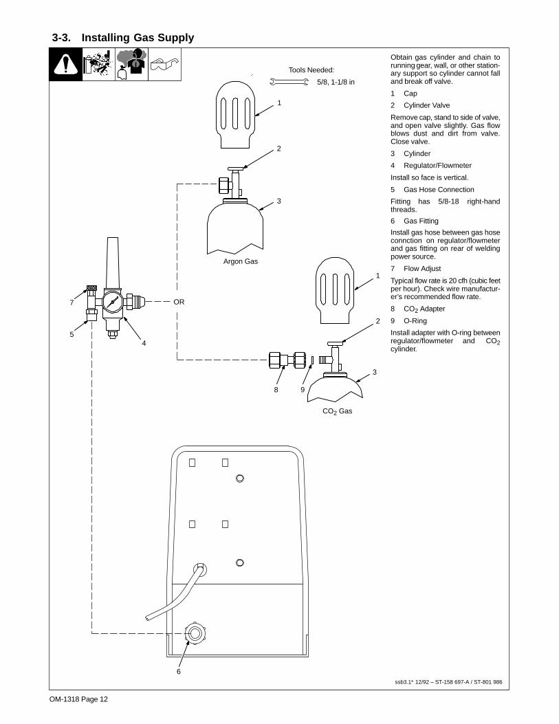
3-3. Installing Gas Supply
Obtain gas cylinder and chain torunning gear, wall, or other station-ary support so cylinder cannot falland break off valve.
1 Cap
2 Cylinder Valve
Remove cap, stand to side of valve,and open valve slightly. Gas flowblows dust and dirt from valve.Close valve.
3 Cylinder
4 Regulator/Flowmeter
Install so face is vertical.
5 Gas Hose Connection
Fitting has 5/8-18 right-handthreads.
6 Gas Fitting
Install gas hose between gas hoseconnction on regulator/flowmeterand gas fitting on rear of weldingpower source.
7 Flow Adjust
Typical flow rate is 20 cfh (cubic feetper hour). Check wire manufactur-er’s recommended flow rate.
8 CO2 Adapter
9 O-Ring
Install adapter with O-ring betweenregulator/flowmeter and CO2cylinder.
Tools Needed:
CO2 Gas
8 9
3
1
2
45
7
1
2
3
Argon Gas
OR
ssb3.1* 12/92 – ST-158 697-A / ST-801 986
5/8, 1-1/8 in
6

OM-1318 Page 13
3-4. Electrical Service Guide
Input Voltage 230
Input Amperes At Rated Output 20
Max Recommended Standard Fuse Or Circuit Breaker Rating In Amperes
Circuit Breaker 1, Time-Delay 2 20
Normal Operating 3 30
Min Input Conductor Size In AWG/Kcmil 14
Max Recommended Input Conductor Length In Feet (Meters)66
(20)
Min Grounding Conductor Size In AWG/Kcmil 14
Reference: 1999 National Electrical Code (NEC)
1 Choose a circuit breaker with time-current curves comparable to a Time Delay Fuse.
2 “Time-Delay” fuses are UL class “RK5” .3 “Normal Operating” (general purpose – no intentional delay) fuses are UL class “K5” (up to and including 60 amp), and UL class “H” ( 65 amp and
above).� Caution: Failure to follow these fuse and circuit breaker recommendations could create an electric shock or fire hazard.
3-5. Selecting A Location And Connecting Input Power
1 Rating Label
Supply correct input power.
2 Plug
3 Receptacle
Connect plug to receptacle.
4 Line Disconnect Device
See Section 3-4.
� Special installation may berequired where gasoline orvolatile liquids are present –see NEC Article 511 or CECSection 20.
ssb2.2* 1/94 – ST-801 988 / 802 401
1
18 in (457 mm) ofspace for airflow
L1L2
L1
L2
2
230 VAC, 1
� Always connectgroundingconductor first.
= GND/PE
4
3
� Do not move or operate unitwhere it could tip.

OM-1318 Page 14
3-6. Installing Wire Spool And Adjusting Hub Tension
S-0499
15/16 in
Standard Wire Spool 1 Lb Wire Spool
When a slight force is neededto turn spool, tension is set.
Tools Needed:
Standard Wire Reel
Part No. 183 312 Part No. 135 615
OM-1318 Page 15
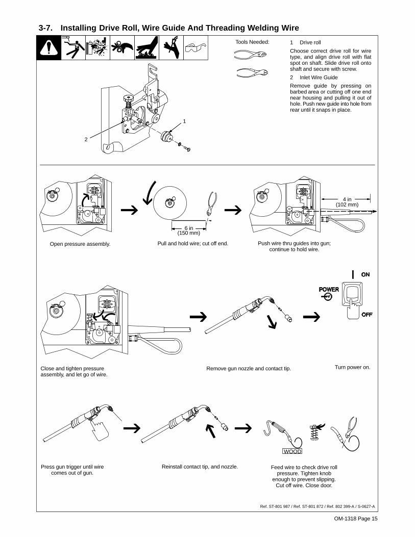
3-7. Installing Drive Roll, Wire Guide And Threading Welding Wire
1 Drive roll
Choose correct drive roll for wiretype, and align drive roll with flatspot on shaft. Slide drive roll ontoshaft and secure with screw.
2 Inlet Wire Guide
Remove guide by pressing onbarbed area or cutting off one endnear housing and pulling it out ofhole. Push new guide into hole fromrear until it snaps in place.
Tools Needed:
1
2
WOOD
6 in(150 mm)
Pull and hold wire; cut off end.
4 in(102 mm)
Open pressure assembly. Push wire thru guides into gun;continue to hold wire.
Close and tighten pressureassembly, and let go of wire.
Remove gun nozzle and contact tip. Turn power on.
Press gun trigger until wirecomes out of gun.
Reinstall contact tip, and nozzle. Feed wire to check drive rollpressure. Tighten knob
enough to prevent slipping.Cut off wire. Close door.
Ref. ST-801 987 / Ref. ST-801 872 / Ref. 802 399-A / S-0627-A

OM-1318 Page 16
3-8. Weld Parameter
Material ThicknessWire Type,
Shielding Gas,And Flow Rate
WireDiameter
(inch)
OperatorControls 1/4 in
(6.4mm)
3/16 in(4.8mm)
1/8 in (3.2mm)
14 ga 16 ga 18 ga 20 ga 22 ga
Voltage Tap* –– –– 3 3 2 2 1 1.023
Wire Speed –– –– 65 60 55 50 50 40
E70S-6 Voltage Tap* 4 3 3 3 2 2 1 1CO2
20 cfh+.030
Wire Speed 60 55 50 40 35 30 25 20
Voltage Tap* 4 3 3 2 2 2 –– ––.035
Wire Speed 50 50 50 45 40 30 –– ––
Voltage Tap* –– –– 3 3 2 2 1 1.023
Wire Speed –– –– 80 70 60 55 50 40
E70S-675% Argon
Voltage Tap* 4 4 3 3 2 2 1 175% Argon25% CO220 cfh+
.030Wire Speed 75 70 60 55 50 40 35 3020 cfh+
Voltage Tap* 4 3 3 2 2 2 1 ––.035
Wire Speed 55 55 50 45 40 35 25 ––
Voltage Tap* 4 4 3 3 2 2 –– ––.030
Wire Speed 70 60 50 40 40 35 –– – –
E71T-GSVoltage Tap* 4 4 3 2 1 –– –– ––
E71T-GSFlux Core .035
Wire Speed 60 50 40 40 40 –– –– – –
Voltage Tap* 4 4 3 –– –– –– –– ––.045
Wire Speed 50 45 40 –– –– –– –– ––
Voltage Tap* –– 4 3 3 3 2 2 ––.023
Wire Speed –– 100 90 80 75 35 30 ––
ER 308Stainless Steel
Voltage Tap* 4 3 3 2 4 2 –– ––Stainless Steel
Tri-Mix20 cfh+
.030Wire Speed 80 70 65 60 50 40 –– ––20 cfh+
Voltage Tap* 4 3 3 –– –– –– –– ––.035
Wire Speed 75 68 60 –– –– –– –– ––
Voltage Tap* –– 4 3 2 1 –– –– ––
Aluminum 5356.030**
Wire Speed –– 100 100 100 100 –– –– ––100% Argon
20 cfh Voltage Tap* –– 4 3 –– –– –– –– ––.035**
Wire Speed –– 100 100 –– –– –– –– ––
*Do not change Voltage switch position while welding. Wire Speed value in Table is a starting value only, and Wire Speed control setting can be finetuned during welding.
** When welding aluminum, for best results, use .023–.035 v-knurled drive roll and a contact tip one size larger than wire diameter... Ref. S-187 939

OM-1318 Page 17
SECTION 4 – OPERATION4-1. Controls
1 Wire Speed Control
Use control to select a wire feedspeed. As Voltage switch setting in-creases, wire speed range also in-creases (see weld setting label inwelding power source).
Ref. ST-187 921
2
4
1
3
2 Voltage Switch
� Switch must “click” into detentposition 1, 2, 3, or 4 for propercontact.
The higher the selected number,the thicker the material that can bewelded (see weld setting label inwelding power source). Do notswitch under load.
3 Voltage Switch - Fan OnlyPosition
In Fan Only position, fan runs butthere is no weld output.
4 Power Switch
OM-1318 Page 18
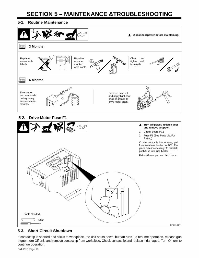
SECTION 5 – MAINTENANCE &TROUBLESHOOTING5-1. Routine Maintenance
� Disconnect power before maintaining.
3 Months
Replaceunreadablelabels.
Repair orreplacecrackedweld cable.
Clean andtighten weldterminals.
6 Months
Blow out orvacuum inside.during heavyservice, cleanmonthly.
Or
Remove drive rolland apply light coatof oil or grease todrive motor shaft.
5-2. Drive Motor Fuse F1
� Turn Off power, unlatch doorand remove wrapper.
1 Circuit Board PC1
2 Fuse F1 (See Parts List ForRating)
If drive motor is inoperative, pullfuse from fuse holder on PC1. Re-place fuse if necessary. To reinstall,push fuse into fuse holder.
Reinstall wrapper, and latch door.
ST-801 867
3/8 in
Tools Needed:
1 2
5-3. Short Circuit Shutdown
If contact tip is shorted and sticks to workpiece, the unit shuts down, but fan runs. To resume operation, release guntrigger, turn Off unit, and remove contact tip from workpiece. Check contact tip and replace if damaged. Turn On unit tocontinue operation.

OM-1318 Page 19
5-4. Cleaning Or Repairing Drive Assembly
� Turn Off power beforecleaning or repairing driveassembly.
1 Wire Spool
2 Nozzle
Cut welding wire off at nozzle. Re-tract wire onto spool and secure.
3 Pressure Roll Arm
4 Cotter Pin
5 Pin
6 Screw
7 Bearing
Remove bearing. Install new bear-ing and secure with screw. Reinstallarm onto pin and secure with cotterpin.
8 Screw
9 Drive Roll
Remove drive roll.
Align drive roll with flat spot onshaft. Slide drive roll onto shaft andsecure with screw.
10 Wire Inlet Guide
Remove guide by pressing onbarbed area or cutting off one endnear housing and pulling it out ofhole. Push new guide into hole fromrear until it snaps in place.
Close door.
2
6 7
8
10
3
49
1
5
Ref. ST-801 987 / Ref. ST-801 872
Tools Needed:
5/64 in
5-5. Replacing Gun Contact Tip
Ref. 802 399-A
� Turn Off power beforereplacing contact tip.
1 Nozzle
2 Contact Tip
Cut off welding wire at contact tip.Remove nozzle.
Remove contact tip and install newcontact tip. Reinstall nozzle.
1
2Tools Needed:

OM-1318 Page 20
5-6. Cleaning Or Replacing Gun Liner
Ref. ST-802 399-A
3/8 in
� Disconnect gun from unit.Tools Needed:
To Reassemble Gun:
Insert new liner.
Install wire outlet guide so that 1/8in (3 mm) of liner sticks out. Handtighten outlet guide, and then tight-en two full turns more.
Cut liner off so that 3/4 in (19 mm)sticks out of head tube.
Install gas diffuser, adapter, contacttip, and nozzle.
Lay gun cable out straightbefore installing new liner.
Head Tube
1/2 in
Remove liner.
Remove nozzle, contact tip,adapter, gas diffuser, and wireoutlet guide.
Blow out gun casing.
OM-1318 Page 21
5-7. Replacing Switch And/Or Head Tube
Ref. ST-800 795-C
1 Remove handlelocking nut.
2 Remove switch housing. Note: If installing newswitch, push switch lead connectors onto terminal ofnew switch (polarity is not important). Install switchback into handle, and secure with handle locking nut.If replacing head tube, continue to end of figure.
3 Slide handle.
4 Secure headtube in vice.
5 Loosen jam nut. Removefrom vice and turn headtube out by hand.
6 Install existing shock washer ontonew head tube. Hand-tighten headtube into connector cable.
7 Place head tube in vice and tightenuntil nuts are tight.
8 Remove from vice. Repositionhandle and install switch housing.Secure with handle locking nut.
� Disconnect gun first.
3/4 in
Tools Needed:

OM-1318 Page 22
5-8. Troubleshooting Table
Trouble Remedy
No weld output; wire does not feed; fan Secure power cord plug in receptacle (see Section 3-5).does not run.
Replace building line fuse or reset circuit breaker if open (see Section 3-5).
Secure gun trigger plug in receptacle (see Section 3-2).
Place Power switch in On position (see Section 4-1).
No weld output; wire does not feed; fanmotor continues to run.
Check Voltage control knob. Switch must “click” into detent position 1, 2, 3, or 4 for proper contact (seeSection 4-1).
Thermostat TP1 open (overheating). Allow fan to run; thermostat closes when unit has cooled (seeSection 2-3).
Check and replace motor fuse F1, if necessary (see Section 5-2).
Have Factory Authorized Service Agent check all board connections and shut down PC1 board.
No weld output; wire feeds. Connect work clamp to get good metal to metal contact.
Replace contact tip (see Section 5-5).
Check for proper connections at polarity changeover board (see Section 3-2).
Low weld output. Connect unit to proper input voltage or check for low line voltage.
Place voltage switch in desired position (see Section 4-1).
Electrode wire feeding stops during Straighten gun cable and/or replace damaged parts (see Section 5-6).welding.
Adjust drive roll pressure (see Section 3-7).
Change to proper drive roll groove (see Section 3-7).
Readjust hub tension (see Section 3-6).
Replace contact tip if blocked (see Section 5-5).
Clean or replace wire inlet guide or liner if dirty or plugged (see Section 5-4 and/or 5-6).
Replace drive roll or pressure bearing if worn or slipping (see Section 5-4).
Secure gun trigger plug in receptacle or repair leads, or replace trigger switch (see Section 3-2).
Check motor fuse F1, and replace if necessary (see Section 5-2).
Check and clear any restrictions at drive assembly and liner (see Section 5-4 and/or 5-6).
Have nearest Factory Authorized Service Agent check drive motor.
OM-1316 Page 23
SECTION 6 – ELECTRICAL DIAGRAM
SB-210 034
Figure 6-1. Circuit Diagram

OM-1318 Page 24
SECTION 7 – MIG WELDING (GMAW) GUIDELINES
7-1. Typical MIG Process Connections
� Weld current can damageelectronic parts in vehicles.Disconnect both batterycables before welding on avehicle. Place work clamp asclose to the weld as possible.
Wire Feeder/Power Source
Workpiece
Gun
Regulator/Flowmeter
Gas
Shielding Gas
Work Clamp
light mig 5/967 / ST-801 909

OM-1318 Page 25
7-2. Typical MIG Process Control Settings
These settings are guidelines only. Material and wire type, joint design, fitup,position, shielding gas, etc. affect settings. Test welds to be sure they comply tospecifications.
NOTE
1/8 or.125 in
Material thickness determines weldparameters.
Convert Material
(.001 in = 1 ampere).125 in = 125 A
Select Wire Size
Wire Size Amperage Range
.030 in
.035 in
.023 in
40 – 145 A
50 – 180 A
30 – 90 A
.035 in
Select Wire Speed
Select Voltage
Wire Recommendation
.030 in
.035 in
.023 in2 in per ampere
1.6 in per ampere
3.5 in per ampere
Wire Speed
2 x 125 A = 250 ipm
1.6 x 125 A = 200 ipm
3.5 x 125 A = 437 ipm
Set voltage midway between high/low voltage.
Low voltage: wire stubs into work
High voltage: arc is unstable (spatter)
125 A based on 1/8 in
Thickness to
(Amperage)
material thickness
Size (Approx.)
Amperage (A)
ipm = inch per minute
Wire speed (amperage) controls weld pe-netration (wire speed = burn-off rate)
Voltage controls height and width ofweld bead.
Ref. ST-801 865
OM-1318 Page 26
7-3. Holding And Positioning Welding Gun
Welding wire is energized when gun trigger is pressed. Before lowering helmet andpressing trigger, be sure wire is no more than 1/2 in (13 mm) past end of nozzle,and tip of wire is positioned correctly on seam.
NOTE
1 Hold Gun and Control GunTrigger
2 Workpiece
3 Work Clamp
4 Electrode Extension (Stickout)1/4 to 1/2 in (6 To 13 mm)
5 Cradle Gun and Rest Hand onWorkpiece
23
5
4
90° 90°
0°-15°
45°
45°
GROOVE WELDS
FILLET WELDS
End View Of Work Angle Side View Of Gun Angle
End View Of Work Angle Side View Of Gun Angle
1
0°-15°
S-0421-A
OM-1318 Page 27
7-4. Conditions That Affect Weld Bead Shape
Weld bead shape depends on gun angle, direction of travel, electrode extension(stickout), travel speed, thickness of base metal, wire feed speed (weld current),and voltage.
NOTE
Short Normal Long
Short Normal Long
10°
10°
GUN ANGLES AND WELD BEAD PROFILES
ELECTRODE EXTENSIONS (STICKOUT)
FILLET WELD ELECTRODE EXTENSIONS (STICKOUT)
Push
Perpendicular Drag
GUN TRAVEL SPEED
Slow Normal Fast
S-0634
OM-1318 Page 28
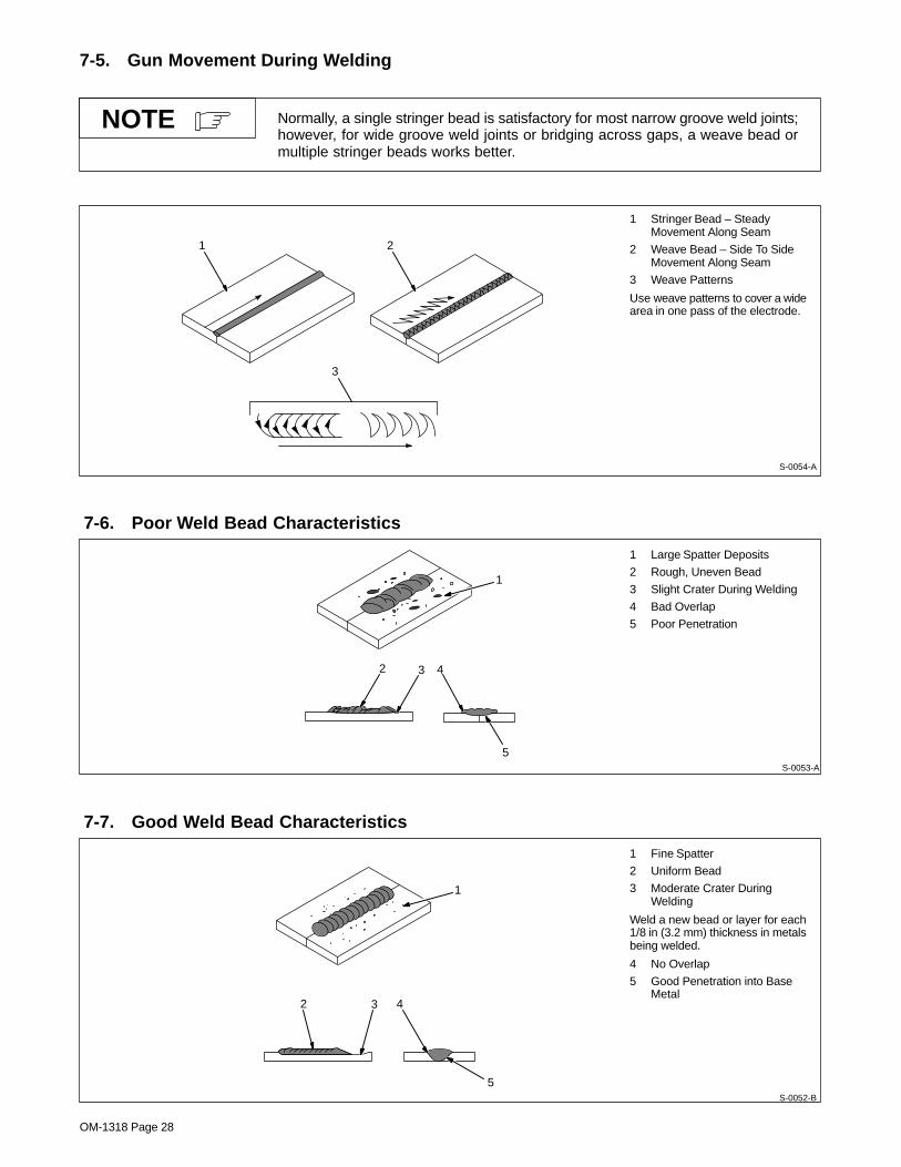
7-5. Gun Movement During Welding
Normally, a single stringer bead is satisfactory for most narrow groove weld joints;however, for wide groove weld joints or bridging across gaps, a weave bead ormultiple stringer beads works better.
NOTE
1 Stringer Bead – SteadyMovement Along Seam
2 Weave Bead – Side To SideMovement Along Seam
3 Weave Patterns
Use weave patterns to cover a widearea in one pass of the electrode.
S-0054-A
3
1 2
7-6. Poor Weld Bead Characteristics
1 Large Spatter Deposits
2 Rough, Uneven Bead
3 Slight Crater During Welding
4 Bad Overlap
5 Poor Penetration
5
42 3
1
S-0053-A
7-7. Good Weld Bead Characteristics
1 Fine Spatter
2 Uniform Bead
3 Moderate Crater DuringWelding
Weld a new bead or layer for each1/8 in (3.2 mm) thickness in metalsbeing welded.
4 No Overlap
5 Good Penetration into BaseMetal
S-0052-B
2 3
1
4
5

OM-1318 Page 29
7-8. Troubleshooting – Excessive Spatter
Excessive Spatter – scattering of molten metal particles thatcool to solid form near weld bead.
S-0636
Possible Causes Corrective Actions
Wire feed speed too high. Select lower wire feed speed.
Voltage too high. Select lower voltage range.
Electrode extension (stickout) too long. Use shorter electrode extension (stickout).
Workpiece dirty. Remove all grease, oil, moisture, rust, paint, undercoating, and dirt from work surface before welding.
Insufficient shielding gas at welding arc. Increase flow of shielding gas at regulator/flowmeter and/or prevent drafts near welding arc.
Dirty welding wire. Use clean, dry welding wire.
Eliminate pickup of oil or lubricant on welding wire from feeder or liner.
7-9. Troubleshooting – Porosity
Porosity – small cavities or holes resulting from gas pocketsin weld metal.
S-0635
Possible Causes Corrective Actions
Insufficient shielding gas at welding arc. Increase flow of shielding gas at regulator/flowmeter and/or prevent drafts near welding arc.
Remove spatter from gun nozzle.
Check gas hoses for leaks.
Place nozzle 1/4 to 1/2 in (6-13 mm) from workpiece.
Hold gun near bead at end of weld until molten metal solidifies.
Wrong gas. Use welding grade shielding gas; change to different gas.
Dirty welding wire. Use clean, dry welding wire.
Eliminate pick up of oil or lubricant on welding wire from feeder or liner.
Workpiece dirty. Remove all grease, oil, moisture, rust, paint, coatings, and dirt from work surface before welding.
Use a more highly deoxidizing welding wire (contact supplier).
Welding wire extends too far out of nozzle. Be sure welding wire extends not more than 1/2 in (13 mm) beyond nozzle.
7-10. Troubleshooting – Excessive Penetration
Good Penetration
Excessive Penetration – weld metal melting through base metaland hanging underneath weld.
Excessive PenetrationS-0639
Possible Causes Corrective Actions
Excessive heat input. Select lower voltage range and reduce wire feed speed.
Increase travel speed.
OM-1318 Page 30
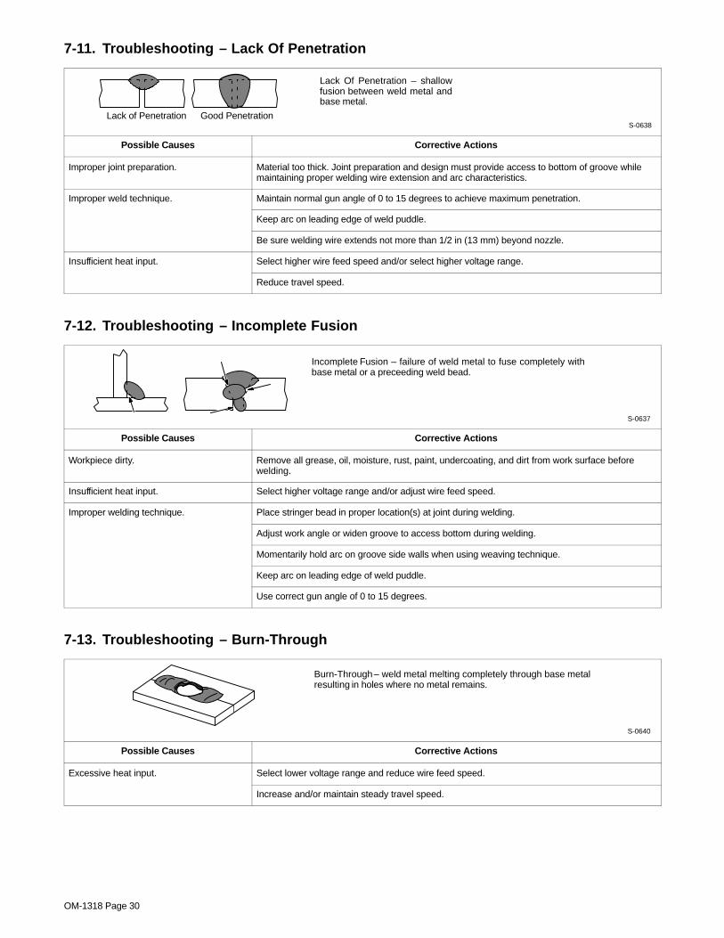
7-11. Troubleshooting – Lack Of Penetration
Lack Of Penetration – shallowfusion between weld metal andbase metal.
Lack of Penetration Good PenetrationS-0638
Possible Causes Corrective Actions
Improper joint preparation. Material too thick. Joint preparation and design must provide access to bottom of groove whilemaintaining proper welding wire extension and arc characteristics.
Improper weld technique. Maintain normal gun angle of 0 to 15 degrees to achieve maximum penetration.
Keep arc on leading edge of weld puddle.
Be sure welding wire extends not more than 1/2 in (13 mm) beyond nozzle.
Insufficient heat input. Select higher wire feed speed and/or select higher voltage range.
Reduce travel speed.
7-12. Troubleshooting – Incomplete Fusion
Incomplete Fusion – failure of weld metal to fuse completely withbase metal or a preceeding weld bead.
S-0637
Possible Causes Corrective Actions
Workpiece dirty. Remove all grease, oil, moisture, rust, paint, undercoating, and dirt from work surface beforewelding.
Insufficient heat input. Select higher voltage range and/or adjust wire feed speed.
Improper welding technique. Place stringer bead in proper location(s) at joint during welding.
Adjust work angle or widen groove to access bottom during welding.
Momentarily hold arc on groove side walls when using weaving technique.
Keep arc on leading edge of weld puddle.
Use correct gun angle of 0 to 15 degrees.
7-13. Troubleshooting – Burn-Through
Burn-Through – weld metal melting completely through base metalresulting in holes where no metal remains.
S-0640
Possible Causes Corrective Actions
Excessive heat input. Select lower voltage range and reduce wire feed speed.
Increase and/or maintain steady travel speed.

OM-1318 Page 31
7-14. Troubleshooting – Waviness Of Bead
Waviness Of Bead – weld metal that is not parallel and does not coverjoint formed by base metal.
S-0641
Possible Causes Corrective Actions
Welding wire extends too far out of nozzle. Be sure welding wire extends not more than 1/2 in (13 mm) beyond nozzle.
Unsteady hand. Support hand on solid surface or use two hands.
7-15. Troubleshooting – Distortion
Distortion – contraction of weld metal during welding that forcesbase metal to move.
Base metal movesin the direction of
the weld bead.S-0642
Possible Causes Corrective Actions
Excessive heat input. Use restraint (clamp) to hold base metal in position.
Make tack welds along joint before starting welding operation.
Select lower voltage range and/or reduce wire feed speed.
Increase travel speed.
Weld in small segments and allow cooling between welds.

OM-1318 Page 32
7-16. Common MIG Shielding Gases
This is a general chart for common gases and where they are used. Many different combinations (mixtures) ofshielding gases have been developed over the years. The most commonly used shielding gases are listed in thefollowing table.
Application
GasSpray Arc Steel Short Circuiting Steel
Short CircuitingStainless Steel
Short CircuitingAluminum
Argon All Positions
Argon + 25% CO2 Flat & Horizontal1 Fillet All Positions All Positions2
CO2 Flat & Horizontal1 Fillet All Positions
Tri-Mix3 All Positions
1 Globular Transfer
2 Single Pass Welding Only
3 90% HE + 7-1/2% AR + 2-1/2% CO2

OM-1318 Page 33
Notes

OM-1318 Page 34
SECTION 8 – PARTS LIST� Hardware is common and
not available unless listed.
Figure 8-1.Complete Assembly
23
4
56
Incl
udes
Item
s
7–12
1
13
14
7
8 9 10
11
12 15
17
16
18 19
20
21
2223
2425
27
26
2829
30
31
32
33 34 35
36
37
383940
41
42
4344
45
46
47
48
49 50
51
52
53
54
44
55
56
57
58
59
60
61
ST-801 996-A
63
63
62

OM-1318 Page 35
DescriptionPartNo.
Dia.Mkgs.
ItemNo.
Figure 8-1. Complete Assembly
Quantity
1 126 838 DRIVE ASSEMBLY, wire (consisting of) 1. . . . . . . . . . . . . . . . . . . . . . . . . . . . . . . . . . . . . . . . . . . . . . . 2 090 416 PIN, hinge 1. . . . . . . . . . . . . . . . . . . . . . . . . . . . . . . . . . . . . . . . . . . . . . . . . . . . . . . . . . . . . . . . . . . . . . . . . 3 124 817 HOUSING, wire drive 1. . . . . . . . . . . . . . . . . . . . . . . . . . . . . . . . . . . . . . . . . . . . . . . . . . . . . . . . . . . . . . . 4 151 828 PIN, cotter hair .054 x .750 1. . . . . . . . . . . . . . . . . . . . . . . . . . . . . . . . . . . . . . . . . . . . . . . . . . . . . . . . . . 5 112 031 LEVER, pressure roll 1. . . . . . . . . . . . . . . . . . . . . . . . . . . . . . . . . . . . . . . . . . . . . . . . . . . . . . . . . . . . . . . 6 090 443 BEARING, ball rdl sgl row .866 OD x .447 width x .315 bore. . . . . . . . . . . . . . . . . . .
(consisting of) 1. . . . . . . . . . . . . . . . . . . . . . . . . . . . . . . . . . . . . . . . . . . . . . . . . . 111 622 SPACER, bearing .196 ID x .310 OD x .500 collar 1. . . . . . . . . . . . . . . . . . . . . . . . . . . . . . . . . . . . . . . .
7 092 237 KNOB, adj tension 1. . . . . . . . . . . . . . . . . . . . . . . . . . . . . . . . . . . . . . . . . . . . . . . . . . . . . . . . . . . . . . . . . 8 090 415 SPRING, cprsn .720 OD x .070 wire x 1.250 1. . . . . . . . . . . . . . . . . . . . . . . . . . . . . . . . . . . . . . . . . . . 9 085 244 WASHER, cupped stl .328 ID x .812 OD x .125 1. . . . . . . . . . . . . . . . . . . . . . . . . . . . . . . . . . . . . . . .
10 085 242 FASTENER, pinned 1. . . . . . . . . . . . . . . . . . . . . . . . . . . . . . . . . . . . . . . . . . . . . . . . . . . . . . . . . . . . . . . . 11 010 224 PIN, spring CS .187 x 1.000 1. . . . . . . . . . . . . . . . . . . . . . . . . . . . . . . . . . . . . . . . . . . . . . . . . . . . . . . . . 12 058 549 GUIDE, wire inlet 1/16 1. . . . . . . . . . . . . . . . . . . . . . . . . . . . . . . . . . . . . . . . . . . . . . . . . . . . . . . . . . . . . . 13 174 609 SCREW, M-.7 x 12 sochd 1. . . . . . . . . . . . . . . . . . . . . . . . . . . . . . . . . . . . . . . . . . . . . . . . . . . . . . . . . . . 14 165 603 ROLL, drive vk groove .030–.035 1. . . . . . . . . . . . . . . . . . . . . . . . . . . . . . . . . . . . . . . . . . . . . . . . . . . . . 15 186 205 HOUSING, drive motor 1. . . . . . . . . . . . . . . . . . . . . . . . . . . . . . . . . . . . . . . . . . . . . . . . . . . . . . . . . . . . . 16 122 385 TERMINAL ASSEMBLY, changeover (consisting of) 1. . . . . . . . . . . . . . . . . . . . . . . . . . . . . . . . . . . . 17 174 504 LINK, jumper 2. . . . . . . . . . . . . . . . . . . . . . . . . . . . . . . . . . . . . . . . . . . . . . . . . . . . . . . . . . . . . . . . . . . . . . 18 186 212 MOTOR, gear 24VDC 1. . . . . . . . . . . . . . . . . . . . . . . . . . . . . . . . . . . . . . . . . . . . . . . . . . . . . . . . . . . . . . 19 SR1 180 791 RECTIFIER 1. . . . . . . . . . . . . . . . . . . . . . . . . . . . . . . . . . . . . . . . . . . . . . . . . . . . . . . . . . . . . . . . . . 20 175 994 SPACER, nylon .750 OD x .390 ID 1. . . . . . . . . . . . . . . . . . . . . . . . . . . . . . . . . . . . . . . . . . . . . . . . . . . 21 210 036 BAFFLE, center 1. . . . . . . . . . . . . . . . . . . . . . . . . . . . . . . . . . . . . . . . . . . . . . . . . . . . . . . . . . . . . . . . . . . 22 073 355 SPRING, cprsn 1. . . . . . . . . . . . . . . . . . . . . . . . . . . . . . . . . . . . . . . . . . . . . . . . . . . . . . . . . . . . . . . . . . . . 23 111 998 PIN, cotter 1. . . . . . . . . . . . . . . . . . . . . . . . . . . . . . . . . . . . . . . . . . . . . . . . . . . . . . . . . . . . . . . . . . . . . . . . 24 111 929 HUB, spool 1. . . . . . . . . . . . . . . . . . . . . . . . . . . . . . . . . . . . . . . . . . . . . . . . . . . . . . . . . . . . . . . . . . . . . . . . 25 134 201 STAND-OFF SUPPORT, PC card 7. . . . . . . . . . . . . . . . . . . . . . . . . . . . . . . . . . . . . . . . . . . . . . . . . . . . 26 PC1 119 539 CIRCUIT CARD, shutdown (consisting of) 1. . . . . . . . . . . . . . . . . . . . . . . . . . . . . . . . . . . . . . . . 27 F1 073 426 FUSE, mintr gl slo-blo 5A 250V 1. . . . . . . . . . . . . . . . . . . . . . . . . . . . . . . . . . . . . . . . . . . . . . . . . .
165 745 CONNECTOR & SOCKETS 1. . . . . . . . . . . . . . . . . . . . . . . . . . . . . . . . . . . . . . . . . . . . . . . . . . . . . . . . . . . . 28 CR2 108 358 CONTACTOR, def prp 25A 2P 24V 1. . . . . . . . . . . . . . . . . . . . . . . . . . . . . . . . . . . . . . . . . . . . . . 29 120 675 BRACKET, mtg motor 1. . . . . . . . . . . . . . . . . . . . . . . . . . . . . . . . . . . . . . . . . . . . . . . . . . . . . . . . . . . . . . 30 FM 210 124 MOTOR, fan 230V 50/60Hz 1. . . . . . . . . . . . . . . . . . . . . . . . . . . . . . . . . . . . . . . . . . . . . . . . . . . . 31 005 656 BLADE, fan 6.000 4wg 30deg 1. . . . . . . . . . . . . . . . . . . . . . . . . . . . . . . . . . . . . . . . . . . . . . . . . . . . . . . . 32 CR1 006 393 RELAY, encl 24VAC DPDT 1. . . . . . . . . . . . . . . . . . . . . . . . . . . . . . . . . . . . . . . . . . . . . . . . . . . . . 33 R1 210 067 RHEOSTAT, WW 25W 12 ohm 1. . . . . . . . . . . . . . . . . . . . . . . . . . . . . . . . . . . . . . . . . . . . . . . . . . . 34 S2 409 477 SWITCH, rotary 25A 5pos 1. . . . . . . . . . . . . . . . . . . . . . . . . . . . . . . . . . . . . . . . . . . . . . . . . . . . . . . 35 048 282 RECEPTACLE w/SOCKETS 1. . . . . . . . . . . . . . . . . . . . . . . . . . . . . . . . . . . . . . . . . . . . . . . . . . . . . . . . 36 147 560 PANEL, side lower 1. . . . . . . . . . . . . . . . . . . . . . . . . . . . . . . . . . . . . . . . . . . . . . . . . . . . . . . . . . . . . . . . . 37 T1 205 419 TRANSFORMER, pwr main 1. . . . . . . . . . . . . . . . . . . . . . . . . . . . . . . . . . . . . . . . . . . . . . . . . . . . . 38 +147 563 WRAPPER 1. . . . . . . . . . . . . . . . . . . . . . . . . . . . . . . . . . . . . . . . . . . . . . . . . . . . . . . . . . . . . . . . . . . . . . . 39 089 899 LATCH 1. . . . . . . . . . . . . . . . . . . . . . . . . . . . . . . . . . . . . . . . . . . . . . . . . . . . . . . . . . . . . . . . . . . . . . . . . . . 40 204 036 LABEL, warning general precautionary 1. . . . . . . . . . . . . . . . . . . . . . . . . . . . . . . . . . . . . . . . . . . . . . . . 41 126 415 CLAMP, saddle 1. . . . . . . . . . . . . . . . . . . . . . . . . . . . . . . . . . . . . . . . . . . . . . . . . . . . . . . . . . . . . . . . . . . . 42 126 416 HANDLE 1. . . . . . . . . . . . . . . . . . . . . . . . . . . . . . . . . . . . . . . . . . . . . . . . . . . . . . . . . . . . . . . . . . . . . . . . . . 43 147 462 PANEL, rear 1. . . . . . . . . . . . . . . . . . . . . . . . . . . . . . . . . . . . . . . . . . . . . . . . . . . . . . . . . . . . . . . . . . . . . . . 44 146 753 BEZEL, 2. . . . . . . . . . . . . . . . . . . . . . . . . . . . . . . . . . . . . . . . . . . . . . . . . . . . . . . . . . . . . . . . . . . . . . . . . . 45 152 118 CORD SET, 250V 1. . . . . . . . . . . . . . . . . . . . . . . . . . . . . . . . . . . . . . . . . . . . . . . . . . . . . . . . . . . . . . . . . . 46 111 443 BUSHING, strain relief .240/.510 1. . . . . . . . . . . . . . . . . . . . . . . . . . . . . . . . . . . . . . . . . . . . . . . . . . . . . 47 605 227 NUT, .750-14 1. . . . . . . . . . . . . . . . . . . . . . . . . . . . . . . . . . . . . . . . . . . . . . . . . . . . . . . . . . . . . . . . . . . . . . 48 GS1 128 751 VALVE, 230VAC 2way 1. . . . . . . . . . . . . . . . . . . . . . . . . . . . . . . . . . . . . . . . . . . . . . . . . . . . . . . . . 49 181 649 RESISTOR, WW fxd 40W 25 ohm 2. . . . . . . . . . . . . . . . . . . . . . . . . . . . . . . . . . . . . . . . . . . . . . . . . . . 50 C1 210 033 CAPACITOR 1. . . . . . . . . . . . . . . . . . . . . . . . . . . . . . . . . . . . . . . . . . . . . . . . . . . . . . . . . . . . . . . . . . 51 022 160 CLAMP, capacitor 1. . . . . . . . . . . . . . . . . . . . . . . . . . . . . . . . . . . . . . . . . . . . . . . . . . . . . . . . . . . . . . . . . . 52 147 566 BASE 1. . . . . . . . . . . . . . . . . . . . . . . . . . . . . . . . . . . . . . . . . . . . . . . . . . . . . . . . . . . . . . . . . . . . . . . . . . . . 53 Z1 204 506 STABILIZER 1. . . . . . . . . . . . . . . . . . . . . . . . . . . . . . . . . . . . . . . . . . . . . . . . . . . . . . . . . . . . . . . . . . 54 147 461 PANEL, front 1. . . . . . . . . . . . . . . . . . . . . . . . . . . . . . . . . . . . . . . . . . . . . . . . . . . . . . . . . . . . . . . . . . . . . . 55 010 368 CLAMP, work 1. . . . . . . . . . . . . . . . . . . . . . . . . . . . . . . . . . . . . . . . . . . . . . . . . . . . . . . . . . . . . . . . . . . . . .
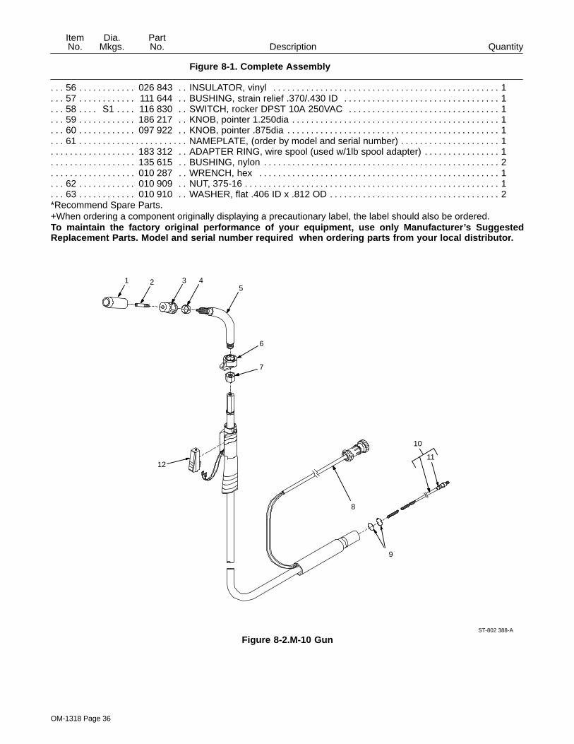
OM-1318 Page 36
DescriptionPartNo.
Dia.Mkgs.
ItemNo.
Figure 8-1. Complete Assembly
Quantity
56 026 843 INSULATOR, vinyl 1. . . . . . . . . . . . . . . . . . . . . . . . . . . . . . . . . . . . . . . . . . . . . . . . . . . . . . . . . . . . . . . . . 57 111 644 BUSHING, strain relief .370/.430 ID 1. . . . . . . . . . . . . . . . . . . . . . . . . . . . . . . . . . . . . . . . . . . . . . . . . . 58 S1 116 830 SWITCH, rocker DPST 10A 250VAC 1. . . . . . . . . . . . . . . . . . . . . . . . . . . . . . . . . . . . . . . . . . . . . 59 186 217 KNOB, pointer 1.250dia 1. . . . . . . . . . . . . . . . . . . . . . . . . . . . . . . . . . . . . . . . . . . . . . . . . . . . . . . . . . . . . 60 097 922 KNOB, pointer .875dia 1. . . . . . . . . . . . . . . . . . . . . . . . . . . . . . . . . . . . . . . . . . . . . . . . . . . . . . . . . . . . . . 61 NAMEPLATE, (order by model and serial number) 1. . . . . . . . . . . . . . . . . . . . . . . . . . . . . . . . . . . . . . . . . . . . . . .
183 312 ADAPTER RING, wire spool (used w/1lb spool adapter) 1. . . . . . . . . . . . . . . . . . . . . . . . . . . . . . . . . . . . 135 615 BUSHING, nylon 2. . . . . . . . . . . . . . . . . . . . . . . . . . . . . . . . . . . . . . . . . . . . . . . . . . . . . . . . . . . . . . . . . . . . . . 010 287 WRENCH, hex 1. . . . . . . . . . . . . . . . . . . . . . . . . . . . . . . . . . . . . . . . . . . . . . . . . . . . . . . . . . . . . . . . . . . . . . .
62 010 909 NUT, 375-16 1. . . . . . . . . . . . . . . . . . . . . . . . . . . . . . . . . . . . . . . . . . . . . . . . . . . . . . . . . . . . . . . . . . . . . . . 63 010 910 WASHER, flat .406 ID x .812 OD 2. . . . . . . . . . . . . . . . . . . . . . . . . . . . . . . . . . . . . . . . . . . . . . . . . . . . .
*Recommend Spare Parts.+When ordering a component originally displaying a precautionary label, the label should also be ordered.To maintain the factory original performance of your equipment, use only Manufacturer’s SuggestedReplacement Parts. Model and serial number required when ordering parts from your local distributor.
1
ST-802 388-A
2 3 45
6
7
9
12
8
10
11
Figure 8-2.M-10 Gun
OM-1318 Page 37
QuantityDescriptionPartNo.
ItemNo.
Figure Figure 8-2. M-10 Gun
1 169 715 NOZZLE, slip type .500 orf flush 1. . . . . . . . . . . . . . . . . . . . . . . . . . . . . . . . . . . . . . . . . . . . . . . . . . . . . 2 ♦ 087 299 TIP, contact scr .023 wire x 1.125. . . . . . . . 2 ♦ 000 067 TIP, contact scr .030 wire x 1.125. . . . . . . . 2 ♦ 000 068 TIP, contact scr .035 wire x 1.125. . . . . . . . 2 ♦ 000 069 TIP, contact scr .045 wire x 1.125. . . . . . . . 3 169 716 ADAPTER, contact tip 1. . . . . . . . . . . . . . . . . . . . . . . . . . . . . . . . . . . . . . . . . . . . . . . . . . . . . . . . . . . . . . 4 170 470 RING, retaining 1. . . . . . . . . . . . . . . . . . . . . . . . . . . . . . . . . . . . . . . . . . . . . . . . . . . . . . . . . . . . . . . . . . . . 5 169 718 TUBE, head 1. . . . . . . . . . . . . . . . . . . . . . . . . . . . . . . . . . . . . . . . . . . . . . . . . . . . . . . . . . . . . . . . . . . . . . . 6 169 738 NUT, locking handle 1. . . . . . . . . . . . . . . . . . . . . . . . . . . . . . . . . . . . . . . . . . . . . . . . . . . . . . . . . . . . . . . . 7 194 524 NUT, jam 1. . . . . . . . . . . . . . . . . . . . . . . . . . . . . . . . . . . . . . . . . . . . . . . . . . . . . . . . . . . . . . . . . . . . . . . . . 8 180 433 CORD, trigger assembly 1. . . . . . . . . . . . . . . . . . . . . . . . . . . . . . . . . . . . . . . . . . . . . . . . . . . . . . . . . . . . 9 079 974 O-RING, .500 ID x .103CS rbr 2. . . . . . . . . . . . . . . . . . . . . . . . . . . . . . . . . . . . . . . . . . . . . . . . . . . . . . .
10 ♦ 194 010 LINER, monocoil .023/.025 wire x 15ft (consisting of) 1. . . . . . . . . . . . . . . . . . . . . . . . . . . . . . . . . 10 ♦ 194 011 LINER, monocoil .030/.035 wire x 15ft (consisting of) 1. . . . . . . . . . . . . . . . . . . . . . . . . . . . . . . . . 10 ♦ 194 012 LINER, monocoil .035/.045 wire x 15ft (consisting of) 1. . . . . . . . . . . . . . . . . . . . . . . . . . . . . . . . . 11 079 975 O-RING, .187 ID x .103CS rbr 1. . . . . . . . . . . . . . . . . . . . . . . . . . . . . . . . . . . . . . . . . . . . . . . . . . . . . . . 12 196 255 SWITCH, trigger 1. . . . . . . . . . . . . . . . . . . . . . . . . . . . . . . . . . . . . . . . . . . . . . . . . . . . . . . . . . . . . . . . . . .
OPTIONALTo maintain the factory original performance of your equipment, use only Manufacturer’s SuggestedReplacement Parts. Model and serial number required when ordering parts from your local distributor.

Warranty Questions?
Call1-800-4-A-MILLERfor your localMiller distributor.
miller_warr 7/00
Your distributor also givesyou ...
ServiceYou always get the fast,reliable response youneed. Most replacementparts can be in yourhands in 24 hours.
SupportNeed fast answers to thetough welding questions?Contact your distributor.The expertise of thedistributor and Miller isthere to help you, everystep of the way.
Effective January 1, 2000(Equipment with a serial number preface of “LA” or newer)This limited warranty supersedes all previous Miller warranties and is exclusive with no other
guarantees or warranties expressed or implied.
LIMITED WARRANTY – Subject to the terms and conditionsbelow, Miller Electric Mfg. Co., Appleton, Wisconsin, warrantsto its original retail purchaser that new Miller equipment soldafter the effective date of this limited warranty is free of defectsin material and workmanship at the time it is shipped by Miller.THIS WARRANTY IS EXPRESSLY IN LIEU OF ALL OTHERWARRANTIES, EXPRESS OR IMPLIED, INCLUDING THEWARRANTIES OF MERCHANTABILITY AND FITNESS.
Within the warranty periods listed below, Miller will repair orreplace any warranted parts or components that fail due tosuch defects in material or workmanship. Miller must benotified in writing within thirty (30) days of such defect orfailure, at which time Miller will provide instructions on thewarranty claim procedures to be followed.
Miller shall honor warranty claims on warranted equipmentlisted below in the event of such a failure within the warrantytime periods. All warranty time periods start on the date thatthe equipment was delivered to the original retail purchaser, orone year after the equipment is sent to a North Americandistributor or eighteen months after the equipment is sent to anInternational distributor.
1. 5 Years Parts – 3 Years Labor
* Original main power rectifiers* Inverters (input and output rectifiers only)
2. 3 Years — Parts and Labor
* Transformer/Rectifier Power Sources* Plasma Arc Cutting Power Sources* Semi-Automatic and Automatic Wire Feeders* Inverter Power Supplies* Intellitig* Engine Driven Welding Generators
(NOTE: Engines are warranted separately bythe engine manufacturer.)
3. 1 Year — Parts and Labor
* DS-2 Wire Feeder* Motor Driven Guns (w/exception of Spoolmate
185 & Spoolmate 250)* Process Controllers* Positioners and Controllers* Automatic Motion Devices* RFCS Foot Controls* Induction Heating Power Sources* Water Coolant Systems* HF Units* Grids* Maxstar 140* Spot Welders* Load Banks* Miller Cyclomatic Equipment* Running Gear/Trailers* Plasma Cutting Torches (except APT & SAF
Models)* Field Options
(NOTE: Field options are covered under TrueBlue for the remaining warranty period of theproduct they are installed in, or for a minimum ofone year — whichever is greater.)
4. 6 Months — Batteries
5. 90 Days — Parts
* MIG Guns/TIG Torches* Induction Heating Coils and Blankets
* APT, ZIPCUT & PLAZCUT Model Plasma CuttingTorches
* Remote Controls
* Accessory Kits
* Replacement Parts (No labor)
* Spoolmate 185 & Spoolmate 250
* Canvas Covers
Miller’s True Blue Limited Warranty shall not apply to:
1. Consumable components; such as contact tips,cutting nozzles, contactors, brushes, slip rings,relays or parts that fail due to normal wear.
2. Items furnished by Miller, but manufactured by others,such as engines or trade accessories. These items arecovered by the manufacturer’s warranty, if any.
3. Equipment that has been modified by any party otherthan Miller, or equipment that has been improperlyinstalled, improperly operated or misused based uponindustry standards, or equipment which has not hadreasonable and necessary maintenance, or equipmentwhich has been used for operation outside of thespecifications for the equipment.
MILLER PRODUCTS ARE INTENDED FOR PURCHASEAND USE BY COMMERCIAL/INDUSTRIAL USERS ANDPERSONS TRAINED AND EXPERIENCED IN THE USEAND MAINTENANCE OF WELDING EQUIPMENT.
In the event of a warranty claim covered by this warranty, theexclusive remedies shall be, at Miller’s option: (1) repair; or (2)replacement; or, where authorized in writing by Miller inappropriate cases, (3) the reasonable cost of repair orreplacement at an authorized Miller service station; or (4)payment of or credit for the purchase price (less reasonabledepreciation based upon actual use) upon return of the goodsat customer’s risk and expense. Miller’s option of repair orreplacement will be F.O.B., Factory at Appleton, Wisconsin, orF.O.B. at a Miller authorized service facility as determined byMiller. Therefore no compensation or reimbursement fortransportation costs of any kind will be allowed.
TO THE EXTENT PERMITTED BY LAW, THE REMEDIESPROVIDED HEREIN ARE THE SOLE AND EXCLUSIVEREMEDIES. IN NO EVENT SHALL MILLER BE LIABLE FORDIRECT, INDIRECT, SPECIAL, INCIDENTAL ORCONSEQUENTIAL DAMAGES (INCLUDING LOSS OFPROFIT), WHETHER BASED ON CONTRACT, TORT ORANY OTHER LEGAL THEORY.
ANY EXPRESS WARRANTY NOT PROVIDED HEREINAND ANY IMPLIED WARRANTY, GUARANTY ORREPRESENTATION AS TO PERFORMANCE, AND ANYREMEDY FOR BREACH OF CONTRACT TORT OR ANYOTHER LEGAL THEORY WHICH, BUT FOR THISPROVISION, MIGHT ARISE BY IMPLICATION,OPERATION OF LAW, CUSTOM OF TRADE OR COURSEOF DEALING, INCLUDING ANY IMPLIED WARRANTY OFMERCHANTABILITY OR FITNESS FOR PARTICULARPURPOSE, WITH RESPECT TO ANY AND ALLEQUIPMENT FURNISHED BY MILLER IS EXCLUDED ANDDISCLAIMED BY MILLER.
Some states in the U.S.A. do not allow limitations of how longan implied warranty lasts, or the exclusion of incidental,indirect, special or consequential damages, so the abovelimitation or exclusion may not apply to you. This warrantyprovides specific legal rights, and other rights may beavailable, but may vary from state to state.
In Canada, legislation in some provinces provides for certainadditional warranties or remedies other than as stated herein,and to the extent that they may not be waived, the limitationsand exclusions set out above may not apply. This LimitedWarranty provides specific legal rights, and other rights maybe available, but may vary from province to province.

PRINTED IN USA 2000 Miller Electric Mfg. Co. 6/00
Miller Electric Mfg. Co.An Illinois Tool Works Company1635 West Spencer StreetAppleton, WI 54914 USA
International Headquarters–USAUSA Phone: 920-735-4505 Auto-AttendedUSA & Canada FAX: 920-735-4134International FAX: 920-735-4125
European Headquarters –United KingdomPhone: 44 (0) 1204-593493FAX: 44 (0) 1204-598066
www.MillerWelds.com
Model Name Serial/Style Number
Purchase Date (Date which equipment was delivered to original customer.)
Distributor
Address
City
State Zip
Please complete and retain with your personal records.
Always provide Model Name and Serial/Style Number.
Call 1-800-4-A-Miller or see our website at www.MillerWelds.comto locate a DISTRIBUTOR or SERVICE AGENCY near you.
Welding Supplies and Consumables
Options and Accessories
Personal Safety Equipment
Service and Repair
Replacement Parts
Training (Schools, Videos, Books)
Technical Manuals (Servicing Informationand Parts)
Circuit Diagrams
Welding Process Handbooks
Contact the Delivering Carrier for:
For assistance in filing or settling claims,contact your distributor and/or equipmentmanufacturer’s Transportation Department.
For Service
Owner’s Record
File a claim for loss or damage duringshipment.
Contact your Distributor for: