MIL-DTL-38999 III / EN3645 subminiature cylindrical … III / EN3645 subminiature cylindrical...
23
™ MIL-DTL-38999 III / EN3645 subminiature cylindrical connectors High performance threaded cylindrical connectors
Transcript of MIL-DTL-38999 III / EN3645 subminiature cylindrical … III / EN3645 subminiature cylindrical...

™
MIL-DTL-38999 III / EN3645 subminiature cylindrical connectors
Q
U A L I F I ED
Q P LAm
phenol
Amphenol
QPL QUALIFIED
High performance threaded cylindrical connectors

table of contentsGENERAL CHARACTERISTICS . . . . . . . . . . . . . . . . . . . . . . . . . . . . . . . . . . . . . . . . . . . . . . . . . . . . . . . . . . . . . . . . . . . . . . . . . . . . . . . . . . . . . . . . . . . . . . . . . . . . . . . . .1
TECHNICAL CHARACTERISTICS• Mechanical characteristics . . . . . . . . . . . . . . . . . . . . . . . . . . . . . . . . . . . . . . . . . . . . . . . . . . . . . . . . . . . . . . . . . . . . . . . . . . . . . . . . . . . . . . . . . . . . . . . . . . . . . . . . .3• Environmental characteristics . . . . . . . . . . . . . . . . . . . . . . . . . . . . . . . . . . . . . . . . . . . . . . . . . . . . . . . . . . . . . . . . . . . . . . . . . . . . . . . . . . . . . . . . . . . . . . . . . . . . . .4• Electrical characteristics . . . . . . . . . . . . . . . . . . . . . . . . . . . . . . . . . . . . . . . . . . . . . . . . . . . . . . . . . . . . . . . . . . . . . . . . . . . . . . . . . . . . . . . . . . . . . . . . . . . . . . . . . . . .5• Insert arrangements . . . . . . . . . . . . . . . . . . . . . . . . . . . . . . . . . . . . . . . . . . . . . . . . . . . . . . . . . . . . . . . . . . . . . . . . . . . . . . . . . . . . . . . . . . . . . . . . . . . . . . . . . . . . . . .6• Coding – Polarization . . . . . . . . . . . . . . . . . . . . . . . . . . . . . . . . . . . . . . . . . . . . . . . . . . . . . . . . . . . . . . . . . . . . . . . . . . . . . . . . . . . . . . . . . . . . . . . . . . . . . . . . . . . . 10
CTV COMPOSITE SHELLS• Presentation . . . . . . . . . . . . . . . . . . . . . . . . . . . . . . . . . . . . . . . . . . . . . . . . . . . . . . . . . . . . . . . . . . . . . . . . . . . . . . . . . . . . . . . . . . . . . . . . . . . . . . . . . . . . . . . . . . . . . 11• Overall dimensions Square flange receptacle . . . . . . . . . . . . . . . . . . . . . . . . . . . . . . . . . . . . . . . . . . . . . . . . . . . . . . . . . . . . . . . . . 11
Jam nut receptacle . . . . . . . . . . . . . . . . . . . . . . . . . . . . . . . . . . . . . . . . . . . . . . . . . . . . . . . . . . . . . . . . . . . . . . . 12 Straight plug . . . . . . . . . . . . . . . . . . . . . . . . . . . . . . . . . . . . . . . . . . . . . . . . . . . . . . . . . . . . . . . . . . . . . . . . . . . . . 12
TV METALLIC SHELLS• Aluminium shells presentation . . . . . . . . . . . . . . . . . . . . . . . . . . . . . . . . . . . . . . . . . . . . . . . . . . . . . . . . . . . . . . . . . . . . . . . . . . . . . . . . . . . . . . . . . . . . . . . . . . . 13• Bronze shells presentation . . . . . . . . . . . . . . . . . . . . . . . . . . . . . . . . . . . . . . . . . . . . . . . . . . . . . . . . . . . . . . . . . . . . . . . . . . . . . . . . . . . . . . . . . . . . . . . . . . . . . . . 13• Stainless steel shells presentation . . . . . . . . . . . . . . . . . . . . . . . . . . . . . . . . . . . . . . . . . . . . . . . . . . . . . . . . . . . . . . . . . . . . . . . . . . . . . . . . . . . . . . . . . . . . . . . . 13• Overall dimensions Square flange receptacle . . . . . . . . . . . . . . . . . . . . . . . . . . . . . . . . . . . . . . . . . . . . . . . . . . . . . . . . . . . . . . . . . 14
Jam nut receptacle . . . . . . . . . . . . . . . . . . . . . . . . . . . . . . . . . . . . . . . . . . . . . . . . . . . . . . . . . . . . . . . . . . . . . . . 14 Straight plug . . . . . . . . . . . . . . . . . . . . . . . . . . . . . . . . . . . . . . . . . . . . . . . . . . . . . . . . . . . . . . . . . . . . . . . . . . . . . 15
PANEL DRILLING FOR COMPOSITE AND METALLIC RECEPTACLES . . . . . . . . . . . . . . . . . . . . . . . . . . . . . . . . . . . . . . . . . . . . . . . . . . . . . . . . . . . . . . . . . . 15
PRINTED CIRCUIT BOARD DRILLING . . . . . . . . . . . . . . . . . . . . . . . . . . . . . . . . . . . . . . . . . . . . . . . . . . . . . . . . . . . . . . . . . . . . . . . . . . . . . . . . . . . . . . . . . . . . . . . . 16
DATA BUS “GROUND PLANE” RECEPTACLES INCLUDING qUADRAx VERSIONS . . . . . . . . . . . . . . . . . . . . . . . . . . . . . . . . . . . . . . . . . . . . . . . . . . . . 19
TVS-Y/TVS-YN HERMETIC RECEPTACLES• Presentation . . . . . . . . . . . . . . . . . . . . . . . . . . . . . . . . . . . . . . . . . . . . . . . . . . . . . . . . . . . . . . . . . . . . . . . . . . . . . . . . . . . . . . . . . . . . . . . . . . . . . . . . . . . . . . . . . . . . . 20• Overall dimensions Square flange receptacle . . . . . . . . . . . . . . . . . . . . . . . . . . . . . . . . . . . . . . . . . . . . . . . . . . . . . . . . . . . . . . . . . 20 Jam nut receptacle . . . . . . . . . . . . . . . . . . . . . . . . . . . . . . . . . . . . . . . . . . . . . . . . . . . . . . . . . . . . . . . . . . . . . . . 21 Solder mounting receptacle . . . . . . . . . . . . . . . . . . . . . . . . . . . . . . . . . . . . . . . . . . . . . . . . . . . . . . . . . . . . . . 21
LANYARD RELEASE PLUGS• Presentation . . . . . . . . . . . . . . . . . . . . . . . . . . . . . . . . . . . . . . . . . . . . . . . . . . . . . . . . . . . . . . . . . . . . . . . . . . . . . . . . . . . . . . . . . . . . . . . . . . . . . . . . . . . . . . . . . . . . . 22• Overall dimensions Lanyard release plug – MIL-STD-1760 . . . . . . . . . . . . . . . . . . . . . . . . . . . . . . . . . . . . . . . . . . . . . . . . . . . . . 22 Lanyard release plug . . . . . . . . . . . . . . . . . . . . . . . . . . . . . . . . . . . . . . . . . . . . . . . . . . . . . . . . . . . . . . . . . . . . . 23
ACCESSORIES• Protection caps . . . . . . . . . . . . . . . . . . . . . . . . . . . . . . . . . . . . . . . . . . . . . . . . . . . . . . . . . . . . . . . . . . . . . . . . . . . . . . . . . . . . . . . . . . . . . . . . . . . . . . . . . . . . . . . . . . 24• Plastic dust caps . . . . . . . . . . . . . . . . . . . . . . . . . . . . . . . . . . . . . . . . . . . . . . . . . . . . . . . . . . . . . . . . . . . . . . . . . . . . . . . . . . . . . . . . . . . . . . . . . . . . . . . . . . . . . . . . . 25• Standard contacts . . . . . . . . . . . . . . . . . . . . . . . . . . . . . . . . . . . . . . . . . . . . . . . . . . . . . . . . . . . . . . . . . . . . . . . . . . . . . . . . . . . . . . . . . . . . . . . . . . . . . . . . . . . . . . . 25• Sealing plugs . . . . . . . . . . . . . . . . . . . . . . . . . . . . . . . . . . . . . . . . . . . . . . . . . . . . . . . . . . . . . . . . . . . . . . . . . . . . . . . . . . . . . . . . . . . . . . . . . . . . . . . . . . . . . . . . . . . . 25• Holding support with dummy receptacles . . . . . . . . . . . . . . . . . . . . . . . . . . . . . . . . . . . . . . . . . . . . . . . . . . . . . . . . . . . . . . . . . . . . . . . . . . . . . . . . . . . . . . . . 25• Torque value for rear accessories . . . . . . . . . . . . . . . . . . . . . . . . . . . . . . . . . . . . . . . . . . . . . . . . . . . . . . . . . . . . . . . . . . . . . . . . . . . . . . . . . . . . . . . . . . . . . . . . . 25
TOOLING• Crimping tools . . . . . . . . . . . . . . . . . . . . . . . . . . . . . . . . . . . . . . . . . . . . . . . . . . . . . . . . . . . . . . . . . . . . . . . . . . . . . . . . . . . . . . . . . . . . . . . . . . . . . . . . . . . . . . . . . . . 26• Insertion and removal tools . . . . . . . . . . . . . . . . . . . . . . . . . . . . . . . . . . . . . . . . . . . . . . . . . . . . . . . . . . . . . . . . . . . . . . . . . . . . . . . . . . . . . . . . . . . . . . . . . . . . . . 26
CONNECTORS ORDERING INFORMATION• Composite and metallic versions Amphenol designation (TV/CTV) . . . . . . . . . . . . . . . . . . . . . . . . . . . . . . . . . . . . . . . . . . . . . . . . . . . . . . . . . 27 Military designation (JD38999) . . . . . . . . . . . . . . . . . . . . . . . . . . . . . . . . . . . . . . . . . . . . . . . . . . . . . . . . . . . . 28• Data bus “ground plane” receptacles including quadrax versions . . . . . . . . . . . . . . . . . . . . . . . . . . . . . . . . . . . . . . . . . . . . . . . . . . . . . . . . . . . . . . . . . . 28• Hermetic versions Amphenol designation (TV) . . . . . . . . . . . . . . . . . . . . . . . . . . . . . . . . . . . . . . . . . . . . . . . . . . . . . . . . . . . . . . 29 Military designation (JD38999) . . . . . . . . . . . . . . . . . . . . . . . . . . . . . . . . . . . . . . . . . . . . . . . . . . . . . . . . . . . . 29• MIL-STD-1760 Lanyard release plugs . . . . . . . . . . . . . . . . . . . . . . . . . . . . . . . . . . . . . . . . . . . . . . . . . . . . . . . . . . . . . . . . . . . . . . . . . . . . . . . . . . . . . . . . . . . . . 30• Lanyard release plugs . . . . . . . . . . . . . . . . . . . . . . . . . . . . . . . . . . . . . . . . . . . . . . . . . . . . . . . . . . . . . . . . . . . . . . . . . . . . . . . . . . . . . . . . . . . . . . . . . . . . . . . . . . . . 31• Cross references (Amphenol versus Mil references) . . . . . . . . . . . . . . . . . . . . . . . . . . . . . . . . . . . . . . . . . . . . . . . . . . . . . . . . . . . . . . . . . . . . . . . . . . . . . . . . 32 • EN3645 ordering information . . . . . . . . . . . . . . . . . . . . . . . . . . . . . . . . . . . . . . . . . . . . . . . . . . . . . . . . . . . . . . . . . . . . . . . . . . . . . . . . . . . . . . . . . . . . . . . . . . . . 32
Tri-Start™ TV-CTV

Amphenol Tri-Start™ TV-CTV
Main features
• shell material - Composite - Aluminium - Marine bronze - Stainless steel
• Finish - Olive drab cadmium plating - Nickel plating - Passivation (for steel versions)
• 9 shell sizes from 09 to 25
• Contacts - More than 60 arrangements of contacts, (including high density versions) - Size 8, 10, 12, 16, 20, 22 D contacts - Signal, power, twinax, coaxial contacts, MOV, optical termini
• Contact protection - 100% scoop-proof shell - Interfacial seal ensures sealing around each contact and
prevents electrolytic erosion
• EMI/RFI protection - Shell to shell bottoming - Grounding fingers on the plug shell
• Quick coupling completely mates and self locks in a 360° turn of the cou-pling nut
• Performs sine and random vibration tests by an anti-decou-pling device
• Receptacles are intermountable with MIL-DTL-38999 series I standard (same panel drilling)
Additional information
Amphenol socapex offers a global solution: besides the TV-CTV wide range of connectors, the following products are available (please consult data sheets):
• Contacts (please refer to data sheet E114)
• Tooling (please refer to data sheet E119)
• Rear accessories (please refer to data sheet E121)
• FTV filtered connectors (please refer to data sheet 12-120)
GENERAL CHARACTERISTICS DESCRIPTIONthe tV-ctV connectors are in accordance with MIl-Dtl-38999 series III standard. these connectors offer the highest per-formance capabilities for both general duty and severe environ-ment applications. besides the most commonly used aluminium shell, different shell materials are available:• the composite connector is a lightweight (17 to 70 % weight
savings), corrosion resistant (withstanding 2000 hours of salt spray expo-sure) connector
• the nickel aluminium bronze connector offers a high corro-sion resistance and robustness for marine applications
• the stainless steel connector provides a firewall capa-bility
the amphenol tV connectors range also offers the follow-ing specific versions:• Inserts compatible with size 8 quadrax• Ground Plane version with a conductive insert for spe-
cific use with coaxial, triaxial or quadrax contacts.• Receptacles with reinforced sealing• hermetic version in Y and n classes• filtered versions using tubular or
planar technology (please consult us)• high density inserts size 23 contacts (please consult us)
APPLICATIONSn Military and aeronautic applications:
battlefield, ground vehicles, aircraftsn Advanced industrial applications:
high vibration requirements, high density

Tri-Start™ TV-CTV
10
11
6
7
9
8
13
1
9
7
12
14
4
2
5
1 Locking ring 8 Receptacle shell 2 Quick coupling thread 9 Contact retention clips 3 Ratchet 10 Crimping pin contact 4 Anti decoupling device 11 Crimping socket contact 5 Plug shell 12 Interfacial seal6 Spring fingers (EMI) 13 Socket insert7 Grommet 14 Pin insert
MECHANICAL CHARACTERISTICS
• Thermoplastic insert
• Silicone rubber back insert and interfacial seal
• Durability: - 500 cycles - 1500 cycles with composite connector " CTV " fitted with " H " and " J " contact types
• shocks: half sine wave of 300 G magnitude during 3ms per EIA364 .27
• sine vibrations: - 60 g from - 55°C to + 175°C (olive drab cadmium finish) - 60 g from - 55°C to 200°C (nickel finish and firewall version)
• Random vibrations per EIA364.28: - 1 G2 / Hz at 175°C olive drab cadmium finish - 1G2 / Hz at 200°C nickel finish and firewall version - 5G2 / Hz at ambient
• Bending moment
• Contact retention force
ELECTRICAL CHARACTERISTICS
Shell size Bending momentNmSeries III MIL-DTL-38999 Amphenol
A 09 11 .3
B 11 33 .9
C 13 45 .2
D 15 56 .5
E 17 67 .8
F 19 79 .1
G 21 90 .4
H 23 101 .7
J 25 113 .0
Contact Size 22D 20 16 12 8 4
Maximum load (N) 45 67 110 110 150 150
Tri-Start™ TV-CTV

ELECTRICAL CHARACTERISTICS
Shellmaterial
Shellfinish
Salt sprayexposure
per EIA364.26
Classnorm
Amphenol Workingtemperature
mini maxi
Composite Electroless NickelO .D cadmium
2000 H2000 H
MJ
CTV-RFCTV-RW
-65°C-65°C
+200°C+175°C
Aluminium Electroless NickelO .D cadmium
48 H500 H
FW
TVS-RFTV-RW
-65°C-65°C
+200°C+175°C
Stainlesssteel
Nickel—
48 H500 H
Sk
TVS-RSTVS-Rk
-65°C-65°C
+200°C+200°C
Bronze — 1000 H TVS-RB -65°C +200°C
ENVIRONMENTAL CHARACTERISTICS
• salt spray exposure and working temperature:
• Waterproof shells
• Humidity: per MIL-DTL-38999: § 3 .29
• Altitude immersion: according to MIL-DTL-38999 III standard (exept hermetics)
• Air leakage < 1 .10 - 7 cm3/s under 1 bar of pressure differential (hermetics only)
• Fluid immersion per EIA364.10: • Hydraulic fluid, per MIL-H-5606
• Turbine fluid, grade JP-8, per MIL-DTL-83133 (NATO TYPE 34)
• Lubricating oil, per MIL-L-7808
• Lubricating oil, per MIL-PRF-23699
• Defrosting fluid, per MIL-A-8243
• Cleaning compound, diluted for cleaning, per MIL-PRF-87937 type I alkaline base
• Gasoline, per ASTM-D-4814
• Gasohol, per A-A-52530
• One part isopropyl alcohol, per TT-I-735, grade A or B ; and 3 parts mineral spirits, per A-A-2904, type II, grade A or P-D-680, type I, by volume
• Coolant, dielectric fluid, synthetic silicate ester base MIL-PRF-47220 (Coolanol 25) or equivalent
• Hydraulic fluid M2-V Chevron oil ST0145LB0001 or equivalent
• Hermetic shells
• Contact resistance• Contact rating - nominal current per contact
• service rating
Shellmateriel
Shellfinish
Salt sprayexposure
per EIA364.26
Classnorm
Amphenol
Workingtemperature
mini maxi
Stainless
steel
Nickel
-48 H
500 HNY
TVS-YNTVS-Y
-65°C-65°C
+200°C+200°C
Contact Size 22D 20 16 12 8* 4*
Current (A) 5 7 .5 13 23 60 100
Contact Size 22D 20 16 12 8* 4*
Resistance (mΩ) 8 4 .7 2 1 .1 0 .6 0 .26
* Please consult us for additional information regarding power inserts Insulation resistance: - at ambiant > 105 Mohms - at maximum temperature > 103 Mohms
ServiceDielectric withstanding voltage (Vrms) Working voltage
At sea level 15000 meters 21000 meters 34000 metersmated unmated mated unmated mated unmated mated unmated Vrms Vdc
M 1300 1300 800 550 800 350 800 200 400 550
I 1800 1800 1000 600 1000 400 1000 200 600 850
II 2300 2300 1000 800 1000 500 1000 200 900 1250
• Dimensions of acceptable contacts and cables
ContactSize
ContactDiameter
mm
Crimp barrel Acceptable cables
Diametermm
Depthmm
Gauge AWGSection mm2
Outside diameter (mm)
Min Average Max
22D 0 .76 0 .88 ± 0 .03 3 .5822 24 26 28
0 .76 1 .20 1 .370 .38 0 .22 0 .15 0 .095
20 1 1 .19 ± 0 .03 5 .3020 22 24 -
1 .02 1 .83 2 .110 .60 0 .38 0 .22 -
16 1 .57 1 .70 ± 0 .03 5 .3016 18 20 -
1 .68 2 .41 2 .771 .34 0 .93 0 .60 -
12 2 .36 2 .54 ± 0 .06 1012 14 - -
2 .46 3 .20 3 .613 .30 1 .94 - -
8 3 .60 4 .6 ± 0 .05 108
4 .50 - 5 .88 .98 Max acceptable: 10mm2
4 5 .70 7 .4 ± 0 .05 124
7 .73 - 8 .421 .10

Tri-Start™ TV-CTV
E 3517-35
M55
22D
YY
17-52
28
(Meets 17-82Boeing Spec)
E 9917-99
I21 220 16
AB
C
D
E
FGH
1
3
4
9
10
16
17
24 31
2532
40
4753
55
524639
A
B
JK
L
M
N
PR
S T
U
V
W
X
Y Z
A
B
C
DEF
G
H
J
K
L
F 1119-11
II1116
12345
17-75
28
Twinax
A
B
Q ��
D 0515-5M516
15-4I412
Y Y Y
D 1515-15
I14 120 16
D 1815-18
I1820
D 1915-19
I1920
15-25**M
22 322D 16
D 3515-35
M37
22D
A
B
CD
E
P
AB
C
D
EFG
H
J
K
LM
NR
AB
C
D
EF
G
H
JK
LM N
P
RS
TU
AB
C
D
EFG
HJ
K
LM
N P
R
ST
U V
1
31
123
45
D 9715-97
I8 4
20 16
Y
AB
C
D
EFG
H
J
KL
M
E 617-6
I612
A
B
C
D
E
F
Y
E 817-8
II816
A
B
C
DE
F
G
H
YQ
E 2617-26
I2620
AB
C
D
E
FGHJ
K
L
M
N
PT
U
VW
XY
Z
aS
b
c
R
123
45
B 3511-35
M13
22D
Y Y Y Y Y
12
3
456
7
8
910
111213
B 9811-98
I620
A
D
B
C
E F
C 413-4
I4
16
AB
CD
C 813-8
I8
20
A
B
C
DE
F
G
H
C 9813-98
I1020
AB
C
D
EF
G
H
JK
C 3513-35
M22
22D
1
22
11-99I720
A
D
B
C
EF
G
123
45
A 359-35M6
22D
Y Y
A 989-98
I320
11-01**
18
Twinax
11-12
112
B 211-2
I2
16
11-4I420
1
23
4
5
6A
CB
9-94I2
20
AB AA B
123
45
Coax Twinax
A
BC
D
17-22
2 12 8 2
12
3
4
5
6 7
8 9
10 11
12
13
1415
16A
B
C
D
17-20**M
4 22D 12 16
17-2M
22D 8 Twinax38 1
1
6
11
17
30
B 511-5
I5
20
A
B
C
DE
13-26M
6+222D 12
AB
CD
E2
1F
123
4
5
6
78 9 10
11
12
1314
1516
1718
19 20
21
2223
24
25
�
INSERT ARRANGEMENTS
Contact Size 22D 20 16 12 8 4
Caption
1 . MIL-DTL-38999 Series III / EN3645 insert arrangement reference2 . TV-CTV insert arrangement3 . Service class
4 . Number of contacts5 . Contact sizes
Front view of male insertOnly the major keyway is illustrated

F 3219-32
I3220
F 3519-35
M66
22D
AB
C
D
E
FG
HJK
L
M
N
P
RS T
UV
W
X
YZa
b
c
d
e
j
f
g
h
1
2
3
9
410
17 25
1624 33
34
42
43
50
51
5763
58
64
66
65
19-28I
26 220 16
19-17M
10 22D 20 16 8 Twinax
YQQ Y
19-30I
29 120 16
19-18M
14 422D 8 Twinax
19-31M
2 1 12 8 Coax 12 22D
41 2
AB
C
D
E
F
GHJ
KL
M
N
P
RS T
UV
W
X
Y
Z
a
b
cd e
AB
C
D
E
FGHJ
K
L
M
N
PR
T
S
U
V
W
XYZa
b
cd
e
g f
AVW
UC
B
gh
S
R M
N KE
B
A
C
D
EFG
H
J
KL
MN
T
S PR
123
45
G 1121-11
I1112
G 1621-16
II1616
Y
G 3521-35
M79
22D
G 3921-39
I37 220 16
A
B
C
D
E
F
G
H
J
K
L
A
B
C
D
EFG
H
J
K
L
M
N
PR
S
21
41
6171
11
3151
79
1 AB
C
D
EF
G
HJ
KLM
NP
R
S
TU
V W
XY
Za
b
cde
f
g
h
ij
kmr
q n
p
123
45
21-48M4
8 Power
G 7521-75
M4
8 Coax or 8 Twinax*
23-66
8 TwinaxM
G 4121-41
I4120
Y Y Q
Q Q
Q
AB
C
D
E
F
G
HJ
KLM
N
P
R
S
T
UV
W
XY
Z
a
b
cde
f
g
h
i
j
km
npq
r
s
t
A
B
C
D A
BC
D
A
B
C
F
D
E
123
45
H 2123-21
II2116
H 3523-35
M10022D
H 5323-53
I5320
A
B
C
D
E
FGH
J
K
L
MN
P
R
S
TU
V
W
X
12
34
5
6
7
816
2535
4656
6777
86
94
95
9697
9899
100
9385
76556645
3424
15
AB
C
D
E
F
G
Hc
J
K
L
M
N
PR
S TU
VW
pq
rX
BBCC
sY
HHDD
tZ
EEu
avb
mn
kz
AA
hy
GG
gx
FF
fe
w
d
23-5440 9 4
22D 16 12M
H 5523-55
I5520
12
34
5
6
2627
28
29
78
910
1112
3433
32
31
30
52 45 46
51 53 47
50 49 48
25
35
40
1920
2122
23 24
4443
4241
1817
1615
1413
3637
3839
AB
C
D
E
F
G
HJK
L
M
N
P
RS
TU V
WX
Y
Z
a
bc
de
fg
h
i
j
km
np
qr
s
tu
vw
x
y
zAA
BBCC
DDEE
FF
GGHH
23-32I
3220
A
B
C
D
E
FG
H
J
K
L
MN
P
R
S
T
U
VW
X
Y
Z
a
a
b
c
de
f
gj
123
45
Y Y Y
J 425-4
I48 820 16
25-8
88 Twinax
A
B
C
D
E
F
G
H
A
B
C
D
E
F
G
H
J
KL
25-7M
222D 8 Twinax
J 1125-11***
N2 920 10 Power
A BC
D
G
H
J
KL
MNP
R
S
T
U
V
W
X
YZ
bc
d
e
f
g
hk
mnp
q
r
s
t
uv
w
x
y
z
AA
BBCC
DD
EE
FF
GGHH
JJ
KK
LL
a
E
FR
1
6
1521
28
1926
3342
53
7884
93
99
6068 82
76
947
16
1824
22
3241
46
5967
74
72
81
7985
29 64
7
36
37
Arrangement 25-8 composé de 8 alvéoles taille 8 isolées de la carrosserie : nous consulter
123
45
23-14I
1412
97
A
B
C
DE
F
G
H
J
K
L
M
N
P
R
S
TU
25-1AI
4 16 4 power
A
B
C
DE
F
G
H
4
A
BK
CJ LP
MN
DH
EG
F
Please consult us for additionnal information about
25-1A insert and contacts.
INSERT ARRANGEMENTS
Contact Size 22D 20 16 12 8 4
Caption
1 . MIL-DTL-38999 Series III / EN3645 insert arrangement reference2 . TV-CTV insert arrangement3 . Service class
4 . Number of contacts5 . Contact sizes
Front view of male insertOnly the major keyway is illustrated

Tri-Start™ TV-CTV
J 4325-43
I23 2020 16
J 6125-61
I6120
25-92**M
92 922D 16
AB
C
D
E
F
G
H
JK
LMN
P
R
S
T
U
V
WX
Y Z
n p a
m w q
k v x r c
b
h u t s d
g f e
AB
C
D
E
F
G
H
JKL
M
N
P
R
S
T
U
V W
XY
Z
a
b
c
d
e
fgh
k
m
n
p
q
r
st u
v
w
xy
z
AA
AB
C
D
E
F
G
HJ
KLMN
PR
S
T
U
V
W
XY
Z a b
c
de
f
g
h
IJm
n
p
q
r
s
t
uv
w
x
y
z
AABB
CC
DD
EE
FF
GG HH
JJ
KKLL
MM
NNPP
k
J 1925-19
I1912
25-17M
22D 8 Twinax36 6
J 2425-24
I12 1216 12
AB
C
D
E
F
G
H
J
K
L
M
N P
R
ST
UV
A B
C
D
E
F
G
HJ
K
L
M
N
P
RS
T
U
VW
X
Y
Z
1
23
45
67
J 2025-20***
N10 13 20 16 8 Twinax 12 Coax
25-26I
16 5 420 12 8 Coax
D
A
B
C
E
F
GH
J
K
L
M
N
P
RS
T
U
V
W
X
Y
Z
a
3
4
5
6
14
15
1
2
7
8
9
10
11
12
13
20
21
22
16
2317
18 19
2524
25-41I
22 3 11 3222D 20 16 12 Coax 8 Twinax
AB
C
D
E
F
G
HJ
K
L
M
N
P
R
S
T
UV
W
X
YZ
a
b
c
d e
fg
h
ijk
mn p
q
r
s t
AU
Ta
bc
d
e
f
st
rqw
pn
m
v ug
hk
S
R
Z
P
N
MY
LK J
XH
B
CV
D
E
W
F
G
25-46I
40 4 220 16 8 Coax
123
45
J 2925-29
I2916
25-37I
3716
J 3525-35
M12822D
A
B
C
D
E
F
G
HJ
K
L
M
N
P
R
S
b
a
Z
Y X
W
V
U
T
df
e
c
AB
C
D
E
F
G
H
JKL
M
N
P
R
S
T
U
V
W
X
Y
Z
ab
c
d
e
f
g
h
k
m
n
p
q r
1
4
7
8
14
15
24
25
35
36
47
48
58
59
70
71
81
82
93
94
104
105
114
115
121
122
125
128
123
45
Y
Q Q
Q
123
45
Y
3 4
1
3
4
5
1324
36
4667
57
79
90
98
101
9789
7866
56 45 3523
12
* Military P/N delivered with 8 twinax and proprietary P/N delivered with size 8 coaxial contacts for RG 180 and RG 195 wire .
** Not available in composite version . *** For MIL STD 1760 application . Y Available in hermetic version . Q Insert with size 8 cavities compatible with Quadrax contacts or differential twinax contacts
if mention in the part-number (see ordering information) . Delivered with twinax contacts for simple braid cable (M17/1760002, AECMA Pr EN 3375 - 003, Raychem
10612, EPD44690, EPD44691) . For information regarding the design of the grommet for size 8 contact (tower grommet, 3 webs, …) and the corresponding piggy back grommet, please consult us . Tower grommet design for size 8 cavities, compatible with standard 900470, 900473… piggy back grommets
J 4325-43
I23 2020 16
J 6125-61
I6120
25-92**M
92 922D 16
AB
C
D
E
F
G
H
JK
LMN
P
R
S
T
U
V
WX
Y Z
n p a
m w q
k v x r c
b
h u t s d
g f e
AB
C
D
E
F
G
H
JKL
M
N
P
R
S
T
U
V W
XY
Z
a
b
c
d
e
fgh
k
m
n
p
q
r
st u
v
w
xy
z
AA
AB
C
D
E
F
G
HJ
KLMN
PR
S
T
U
V
W
XY
Z a b
c
de
f
g
h
IJm
n
p
q
r
s
t
uv
w
x
y
z
AABB
CC
DD
EE
FF
GG HH
JJ
KKLL
MM
NNPP
k
J 1925-19
I1912
25-17M
22D 8 Twinax36 6
J 2425-24
I12 1216 12
AB
C
D
H
J
K
L
M
N P
R
T
UV
A B
C
D
E
F
G
HJ
K
L
M
N
P
RS
T
U
VW
X
Y
Z
1
23
45
67
J 2025-20***
N10 13 20 16 8 Twinax 12 Coax
25-26I
16 5 420 12 8 Coax
D
A
B
C
E
F
GH
J
K
L
M
N
P
RS
T
U
V
W
X
Y
Z
a
3
4
5
6
14
15
1
2
7
8
9
10
11
12
13
20
21
22
16
2317
18 19
2524
25-41I
22 3 11 3222D 20 16 12 Coax 8 Twinax
AB
C
D
E
F
G
HJ
K
L
M
N
P
R
S
T
UV
W
X
YZ
a
b
c
d e
fg
h
ijk
mn p
q
r
s t
AU
Ta
bc
d
e
f
st
rqw
pn
m
v ug
hk
S
R
Z
P
N
MY
LK J
XH
B
CV
D
E
W
F
G
25-46I
40 4 220 16 8 Coax
123
45
J 2925-29
I2916
25-37I
3716
J 3525-35
M12822D
A
B
C
D
E
F
G
HJ
K
L
M
N
P
R
S
b
a
Z
Y X
W
V
U
T
df
e
c
AB
C
D
E
F
G
H
JKL
M
N
P
R
S
T
U
V
W
X
Y
Z
ab
c
d
e
f
g
h
k
m
n
p
q r
1
4
7
8
14
15
24
25
35
36
47
48
58
59
70
71
81
82
93
94
104
105
114
115
121
122
125
128
123
45
Y
Q Q
Q
123
45
Y
3 4
1
3
4
5
1324
36
4667
57
79
90
98
101
9789
7866
56 45 3523
12
INSERT ARRANGEMENTS
Contact Size 22D 20 16 12 8 4
Caption
Front view of male insertOnly the major keyway is illustrated
1 . MIL-DTL-38999 Series III / EN3645 insert arrangement reference2 . TV-CTV insert arrangement3 . Service class
4 . Number of contacts5 . Contact sizes

Legend: ** Grounded version (metallic insert for use with coaxial, twinax or quadrax contacts, for receptacle only) . For details, please refer to page 19 *** 25-11 and 25-20 arrangements used for interconnection per MIL-STD-1760 O 21-75 delivered with TWINAX contacts when ordered under the Mil P/N
ArrangementsService
Class
Totalnumber
ofcontacts
Number and size of contacts Grounded insert
availability**
qua
drax
avai
labl
e
CTV TV 22D 20 16 16G** 12 12coax 12G** 10
power8
power 8 coax8 triax
ortwinax
8G** 4power P S
9-5** 9-5** 1 1 X X X9-35 9-35 M 6 69-94 9-94 M 2 29-98 9-98 I 3 3
11-1 1 111-2** 11-2** 2 2 X X11-2 11-2 I 2 211-4 11-4 I 4 411-5 11-5 I 5 5
11-12 11-12 II 1 111-35 11-35 M 13 1311-98 11-98 I 6 611-99 11-99 I 7 713-4** 13-4** 4 4 X13-4 13-4 I 4 413-8 13-8 I 8 8
13-26 13-26 M 8 6 213-35 13-35 M 22 2213-98 13-98 I 10 1015-5** 15-5** 5 5 X15-5 15-5 II 5 5
15-15 15-15 I 15 14 115-18 15-18 I 18 1815-19 15-19 I 19 19
15-25 M 25 22 315-35 15-35 M 37 3715-97 15-97 I 12 8 417-2 17-2 M 39 38 1
17-6** 17-6** 6 6 X17-6 17-6 I 6 6
17-8** 17-8** 8 8 X X17-8 17-8 II 8 8
17-20 M 20 16 417-22** 17-22** 4 2 2 X X X17-22 17-22 4 2 2 X17-26 17-26 I 26 2617-35 17-35 M 55 5517-52 17-52 1 2 X
17-52** 17-52** 2 X X X17-75 17-75 I 2 217-99 17-99 I 23 21 2
19-11** 19-11** 11 11 X X19-11 19-11 II 11 11 X X19-17 19-17 M 17 10 1 4 219-18 19-18 M 18 14 419-28 19-28 I 28 26 219-30 19-30 I 30 29 119-31 19-31 M 15 12 1 2 X19-32 19-32 I 32 3219-35 19-35 M 66 6621-11 21-11 I 11 11
21-16** 21-16** 16 16 X21-26 21-26 II 16 1621-35 21-35 M 79 7921-39 21-39 I 39 37 221-41 21-41 I 41 4121-48 21-48 4 421-75O 21-75O M 4 4 or 4
21-75** 21-75** 4 4 X X X

Tri-Start™ TV-CTV
RECEPTACLE — Front face shown
Major key
ARϒBSC
BRϒBSC
CRϒBSC
DRϒBSC
Major key
APϒBSC
BPϒBSC
CPϒBSC
DPϒBSC
PLUG — Front face shown
Legend: ** Grounded version (metallic insert for use with coaxial, twinax or quadraxcontacts, for receptacle only) . For details, please refer to page 19 *** 25-11 and 25-20 arrangements used for interconnection per MIL-STD-1760
To avoid cross-plugging problems in applications requiring the use of more than one MIL-DTL-38999 III connector of the same size, alternate key-rotations are available as indicated in the accompanying chart . As shown in the diagram below, the sec-ondary keys rotate clockwise from the major one .
In the reference system, the polarizationis shown by the letters N, A, B, C, D or E .
ArrangementsService
Class
Totalnumber
ofcontacts
Number and size of contacts Grounded insert
availability**
qua
drax
avai
labl
e
CTV TV 22D 20 16 16G** 12 12coax 12G** 10
power8
power 8 coax8 triax
ortwinax
8G** 4power P S
23-6 23-6 M 6 6 X23-6** 23-6** M 6 6 X X X
23-14** 23-14** 14 14 X X23-14 23-14 I 14 1423-21 23-21 II 21 21
23-21** 23-21** II 21 21 X X23-32 23-32 I 32 3223-35 23-35 M 100 10023-53 23-53 I 53 5323-54 23-54 M 53 40 9 423-55 23-55 I 55 5525-4 25-4 I 56 48 825-7 25-7 M 99 97 2 X25-8 25-8 M 8 8 X
25-8** 25-8** M 8 8 X X X25-11** 25-11** N 11 2 925-1A 25-1A 8 4 425-17 25-17 M 42 36 6 X25-19 25-19 I 19 19
25-19** 25-19** I 19 19 X25-20** 25-20** N 30 10 13 4* 3 X25-24 25-24 I 24 12 1225-26 25-26 I 25 16 5 4
25-29** 25-29** I 29 29 X25-29 25-29 I 29 2925-35 25-35 M 128 12825-37 25-37 I 37 3725-41 25-41 I 41 22 3 11 2* 325-43 25-43 I 43 23 2025-46 25-46 I 46 40 4 225-61 25-61 I 61 61
25-92 M 101 92 9
Shellsize
Codingidentification
letter
AR°or AP°
BSC
BR°or BP°
BSC
CR°or CP°
BSC
DR°or DP°
BSC
9
N 105 140 215 265A 102 132 248 320B 80 118 230 312C 35 140 205 275D 64 155 234 304E 91 131 197 240
1113
and15
N 95 141 208 236A 113 156 182 292B 90 145 195 252C 53 156 220 255D 119 146 176 298E 51 141 184 242
17and19
N 80 142 196 293A 135 170 200 310B 49 169 200 244C 66 140 200 257D 62 145 180 280E 79 153 197 272
2123
and25
N 80 142 196 293A 135 170 200 310B 49 169 200 244C 66 140 200 257D 62 145 180 280E 79 153 197 272
CODING - POLARIzATION

S2 PLACES
R12 PLACES
23.11 ± 0.13
ML
Z1
B THREADCLASS 2A0.1P-0.3L-TS
V THREADMETRIC
T
0.13 M
R22 PLACES
Relativeto A21,87
View Dfor size 8 coaxial
only4 PLACES
TT
S2 PLACES
R12 PLACES
23.11 ± 0.13
ML
Z1
B THREADCLASS 2A0.1P-0.3L-TS
V THREADMETRIC
T
0.13 M
R22 PLACES
Relativeto A21,87
View Dfor size 8 coaxial
only4 PLACES
TT
CTV COMPOSITE SHELLS
PresentationTri-Start CTV series are in accordance with MIL-DTL-38999-III .
The composite used for this series was developed to meet aeronautic market requirements:
• Mass saving (20-40% compared to Aluminium versions / 60-70% compared to stainless steel versions)
• Great corrosion resistance
• Useful life extension
• Great EMI-RFI shielding
CTV Connectors are intermatable and intermountable with TV metallic versions .
Note: Locking rings and hexagonal nuts are delivered without plating (black)
Main characteristics• Shell to shell conductivity: - Individual value: 3 millivolts
- Value after test: 6 millivolts
• Durability: - 500 cycles with standards contacts - 1500 cycles with "H” type SAE AS39029 pin contacts and “J” type SAE AS39029 socket contacts
• Ozone exposure: MIL-DTL-38999 § 4 .5 .28 / EIA 364 .14 .
• Fungus resistance conforms to: MIL-STD-810, method 508 .
• Standard MIL wiring tools
Overall dimensions - Composite versions
For panel drilling, please refer to page 15For PCB contacts stickout, please refer to page 16Maximum panel sickness for rear panel mounting: 5,94mm from size 9 to 19 / 5,18mm from size 21 to 25 .
CTVP00RW JD38999/20JCTVPs00RF JD38999/20MSquare flange receptacle
Shell size BThread(inches)
LMax
(mm)
M+0 .00-0 .13
(mm)
R1
(mm)R2
(mm)
S±0 .25
(mm)
T+0 .20-0 .13
(mm)
Z1Max
(mm)
TT+0 .20-0 .13
(mm)
V threadmetricMIL-DTL-38999
Series IIIAmphenol
SocapexA 9 .6250 13 .055 19 .685 18 .26 15 .09 23 .83 3 .25 5 .03 5 .49 M12x1-6gB 11 .7500 13 .055 19 .685 20 .62 18 .26 26 .19 3 .25 5 .03 4 .93 M15x1-6gC 13 .8750 13 .055 19 .685 23 .01 20 .62 28 .58 3 .25 5 .03 4 .93 M18x1-6gD 15 1 .0000 13 .055 19 .685 24 .61 23 .01 30 .96 3 .25 5 .03 4 .39 M22x1-6gE 17 1 .1875 13 .055 19 .685 26 .97 24 .61 33 .32 3 .25 5 .03 4 .93 M25x1-6gF 19 1 .2500 13 .055 19 .685 29 .36 26 .97 36 .53 3 .25 5 .03 4 .93 M28x1-6gG 21 1 .3750 13 .843 18 .923 31 .75 29 .36 39 .67 3 .25 5 .79 4 .93 M31x1-6gH 23 1 .5000 13 .843 18 .923 34 .93 31 .75 42 .88 3 .91 5 .79 6 .15 M34x1-6gJ 25 1 .6250 13 .843 18 .923 38 .10 34 .93 46 .02 3 .91 5 .79 6 .15 M37x1-6g

Tri-Start™ TV-CTV
CTϒ
SH
Aϒ
Shell sizes 9/11 - 22.12Shell sizes 13/25 - 22.30
2.31 MAX
V THREADMETRIC
B THREADCLASS 2A
0.1P-0.3L-TS
SHELLSIZE TO 9/119.11 MAXSHELLSIZE TO 13/259.04 MAX
PANELTHICKNESS
1.57 MIN3.18 MAX
31.34 MAX
Q
15.01
B THREADCLASS 2B0.1P-0.3L-TS
V THREADMETRIC
+ 0.08– 09.12 MAX
31.34 MAX
Q
15.01
B THREADCLASS 2B0.1P-0.3L-TS
V THREADMETRIC
+ 0.08– 09.12 MAX
CTV06 RW JD38999/26JCTVs06 RF JD38999/26MStraight plug
CTV07 RW JD38999/24JCTVs07 RF JD38999/24MJam nut receptacle
For panel drilling, please refer to page 15For PCB contacts stickout, please refer to page 16
Shell size A+0 .00-0 .25
(mm)
BThread(inches)
CMax
(mm)
H Hex+0 .43-0 .41
(mm)
S+0 .28-0 .25
(mm)
T±0 .25-0 .00
(mm)
V threadmetric
Hex nutmax torque
N.mMIL-DTL-38999Series III
AmphenolSocapex
A 9 16 .99 .6250 30 .45 22 .23 26 .97 17 .70 M12x1-6g 4 .1B 11 19 .53 .7500 35 .20 25 .40 31 .75 20 .88 M15x1-6g 5 .3C 13 24 .26 .8750 38 .38 30 .17 34 .92 25 .58 M18x1-6g 6 .9D 15 27 .53 1 .0000 41 .55 33 .32 38 .10 28 .80 M22x1-6g 8 .6E 17 30 .68 1 .1875 44 .73 36 .52 41 .28 31 .98 M25x1-6g 9 .8F 19 33 .86 1 .2500 49 .50 39 .67 46 .02 35 .15 M28x1-6g 10 .9G 21 37 .06 1 .3750 52 .65 42 .87 49 .22 38 .28 M31x1-6g 12 .7H 23 40 .00 1 .5000 55 .85 46 .02 52 .37 41 .50 M34x1-6g 13 .8J 25 43 .41 1 .6250 59 .00 50 .80 55 .57 44 .68 M37x1-6g 15
Shell size BThread(inches)
qMax
(mm)
V threadmetric(mm)MIL-DTL-38999
Series IIIAmphenol
SocapexA 9 .6250 21 .82 M12x1-6gB 11 .7500 24 .99 M15x1-6gC 13 .8750 29 .39 M18x1-6gD 15 1 .0000 32 .49 M22x1-6gE 17 1 .1875 35 .69 M25x1-6gF 19 1 .2500 38 .48 M28x1-6gG 21 1 .3750 41 .68 M31x1-6gH 23 1 .5000 44 .88 M34x1-6gJ 25 1 .6250 47 .98 M37x1-6g
Tri-Start™ TV-CTV

Amphenol Tri-Start™ TV-CTV
For panel drilling, please refer to page 15For PCB contacts stickout, please refer to page 16
TV METALLIC SHELLSTVS-F / TV-W Aluminium shells
Presentation
Aluminium TV shell connectors are used in professional and international electronic defense programs in standard environmental conditions .
Main characteristics
• Material shell: Aluminium alloy .
• Shell to shell conductivity: - 1 mΩ for F class - 2 .5 mΩ for W class
• EMI-RFI shielding: - 65 db to 10 Ghz, F class - 50 db to 10 Ghz, W class - 85 db to 1 Ghz, F and W class• Standard MIL wiring tools
TVS-B Marine bronze shells
Presentation
TVS-B bronze shell connectors are not defined in MIL-DTL-38999-III-J standard but they are based on its requirements .
TVS-B connectors conform to the European standard CECC 75 .201 .002 . (deviation F485 to be added for plug)
This series was initially selected by the British Navy for a new generation of ships . By extension a lot of the NATO Navy choose this series as a standard of interconnection .
TVS-B connector is now the most popular circular connector to be used in marine application .
Main characteristics
• Material shell: Nickel aluminum bronze DGS 1043 .
• EMI-RFI shielding: > 65 dB at 100 Mhz to 10 Ghz .
• Standard MIL wiring tools
TVS-K / TVS-S Stainless steel shells
Presentation
Stainless steel shell connectors are used in high temperature environments and in harsh vibration conditions . They provide FIREWALL capabilities .
Main characteristics
• Thermosetting insert
• Working temperature: - 65°C, + 200°C - 1093°C during 20 minutes
• Shell to shell conductivity: - 10 millivolts for k class - 1 millivolts for S class
• EMI-RFI shielding: - 45 dB mini at 10 Ghz for k class - 65 dB mini at 10 Ghz for S class

Tri-Start™ TV-CTV
S2 PLACES
0.13 M
T 4 PLACES TT 4 PLACES
R1
2 PLACESR2
2 PLACES
22.99
ML
ZB
+0.15 0
For size 8 coaxialonly
Relativeto A21,87
V THREADMETRIC
CTϒ
SH
Aϒ
K REF 2,31 MAXVB
N MAXPANEL THICKNESS1,57 MIN, 3,18 MAX
Size 9/11 = 9,45Size 13/25 = 9,37
Size 9/11 = 22,12Size 13/25 = 22,30
For size 8 coaxialonly
Relativeto A20,17
OVERALL DIMENSIONS / METALLIC VERSIONS
TVP00RW JD38999/20WTVPs00RF JD38999/20FTVPs00RBTVPs00RK JD38999/20KTVPs00Rs JD38999/20sSquare flange receptacle
TV07RW JD38999/24WTVs07RF JD38999/24FTVs07RBTVs07RK JD38999/24KTVs07Rs JD38999/24sJam nut receptacle
For panel drilling, please refer to page 15For PCB contacts stickout, please refer to page 16Maximum panel sickness for rear panel mounting: 5,94mm from size 9 to 19 / 5,18mm from size 21 to 25 .
S2 PLACES
R12 PLACES
23.11 ± 0.13
ML
Z1
B THREADCLASS 2A0.1P-0.3L-TS
V THREADMETRIC
T
0.13 M
R22 PLACES
Relativeto A21,87
View Dfor size 8 coaxial
only4 PLACES
TT
Shell size Bthread
Class 2A0.1P-0.3L-TS
(inches)
LMax
(mm)
M+0 .00-0 .13
(mm)
R1
(mm)R2
(mm)
S±0 .25
(mm)
T+0 .20-0 .13
(mm)
Z1Max
(mm)
TT+0 .20-0 .13
(mm)
V threadmetricMIL-DTL-38999
Series IIIAmphenol
Socapex
A 9 .6250 11 .91 20 .83 18 .26 15 .09 23 .83 3 .25 3 .89 5 .49 M12x1-6gB 11 .7500 11 .91 20 .83 20 .62 18 .26 26 .19 3 .25 3 .89 4 .93 M15x1-6gC 13 .8750 11 .91 20 .83 23 .01 20 .62 28 .58 3 .25 3 .89 4 .93 M18x1-6gD 15 1 .0000 11 .91 20 .83 24 .61 23 .01 30 .96 3 .25 3 .89 4 .39 M22x1-6gE 17 1 .1875 11 .91 20 .83 26 .97 24 .61 33 .32 3 .25 3 .89 4 .93 M25x1-6gF 19 1 .2500 11 .91 20 .83 29 .36 26 .97 36 .53 3 .25 3 .89 4 .93 M28x1-6gG 21 1 .3750 12 .70 20 .07 31 .75 29 .36 39 .67 3 .25 4 .65 4 .93 M31x1-6gH 23 1 .5000 12 .70 20 .07 34 .93 31 .75 42 .88 3 .91 4 .65 6 .15 M34x1-6gJ 25 1 .6250 12 .70 20 .07 38 .10 34 .93 46 .02 3 .91 4 .65 6 .15 M37x1-6g
Shell size Bthread
Class 2A0.1P-0.3L-TS
(inches)
A+0 .00-0 .25
(mm)
CMax
(mm)
H Hex+0 .43-0 .41
(mm)
S+0 .28-0 .25
(mm)
T±0 .25-0 .00
(mm)
V threadmetric
Hex nutmax torque
N.mMIL-DTL-38999Series III
AmphenolSocapex
A 9 .6250 16 .99 30 .45 22 .23 26 .97 17 .70 M12x1-6g 4 .1B 11 .7500 19 .53 35 .20 25 .40 31 .75 20 .88 M15x1-6g 5 .3C 13 .8750 24 .26 38 .38 30 .17 34 .93 25 .58 M18x1-6g 6 .9D 15 1 .0000 27 .53 41 .55 33 .32 38 .10 28 .80 M22x1-6g 8 .6E 17 1 .1875 30 .68 44 .73 36 .52 41 .28 31 .98 M25x1-6g 9 .8F 19 1 .2500 33 .86 49 .50 39 .67 46 .02 35 .15 M28x1-6g 10 .9G 21 1 .3750 37 .06 52 .65 42 .87 49 .23 38 .28 M31x1-6g 12 .7H 23 1 .5000 40 .00 55 .85 46 .02 52 .37 41 .50 M34x1-6g 13 .8J 25 1 .6250 43 .41 59 .00 50 .80 55 .58 44 .68 M37x1-6g 15

Amphenol Tri-Start™ TV-CTV
Q (F485)Q
31.34 MAX
BV
9.12 MAX
15.01 + 0.1– 0.0
For size 8 coaxialonly
Relativeto A
42,06 MAX
Jam nut receptaclerear panel mounting
Ø E
F
G
V
R3
R4
Ø B
4 Ø W
Square flange receptaclerear panel mounting
V
R3
R4 4 Ø W
Square flange receptaclefront panel mounting
Ø D
PANEL DRILLING FOR COMPOSITE AND METALLIC RECEPTACLES
TV06RW JD38999/26WTVs06RF JD38999/26FTVs06RBTVs06RK JD38999/26KTVs06Rs JD38999/26sStraight plug
* Conforms to CECC 75 .201 .002
Shell size Bthread
Class 2A0.1P-0.3L-TS
(mm)
qMax
(mm)
V threadmetric(mm)
q (F485)*(mm)MIL-DTL-38999
Series IIIAmphenol
Socapex
A 9 .6250 21 .82 M12x1-6g 21 .1B 11 .7500 24 .62 M15x1-6g 23 .8C 13 .8750 28 .98 M18x1-6g 28 .2D 15 1 .0000 32 .16 M22x1-6g 31 .4E 17 1 .1875 35 .33 M25x1-6g 36 .5F 19 1 .2500 38 .10 M28x1-6g 39 .3G 21 1 .3750 41 .28 M31x1-6g 42 .5H 23 1 .5000 44 .45 M34x1-6g 45 .3J 25 1 .6250 47 .63 M37x1-6g 48 .4
Shell sizeR3
(mm)R4
(mm)
VMini(mm)
ØW+0
-0 .25(mm)
GMini(mm)
ØEMini(mm)
F+0
-0 .25(mm)
ØBMini(mm)
ØDMini(mm)MIL-DTL-38999
Series IIIAmphenol
Socapex
A 9 18 .26 15 .09 24 .60 3 .25 27 .80 17 .70 16 .99 16 .66 13 .11B 11 20 .62 18 .26 27 .00 3 .25 32 .60 20 .88 19 .53 20 .22 15 .88C 13 23 .01 20 .62 31 .50 3 .25 36 .00 25 .58 24 .26 23 .42 19 .05D 15 24 .61 23 .01 34 .50 3 .25 39 .60 28 .80 27 .53 26 .59 23 .01E 17 26 .97 24 .61 28 .00 3 .25 43 .30 31 .98 30 .68 30 .96 25 .81F 19 29 .36 26 .97 40 .50 3 .25 47 .00 35 .16 33 .86 32 .94 28 .98G 21 31 .75 29 .36 44 .00 3 .25 50 .60 38 .28 37 .06 36 .12 32 .16H 23 34 .93 31 .75 47 .00 3 .81 54 .20 41 .50 40 .01 39 .29 34 .93J 25 38 .10 34 .93 50 .00 3 .81 59 .70 44 .68 43 .41 42 .47 37 .69

Amphenol Tri-Start™ TV-CTV
Tri-Start™ TV-CTV
PRINTED CIRCUIT BOARD DRILLINGReceptacles equipped with size 22D standard PCB contacts (CI) Diameter of the size 22 contact tail: 0,5 mm for gold plated tail 0,6 mm for tin plated (lead free or not) tailThe marking of contact cavities is shown on the mating side view of the male receptacle . The marking on the female plug is symmetrical in relation to the +X/-Y axis .
Ø 0.8 mini
+Y
+X
–Y
–X
79 contactssize 22D
21 71
11
51
77
1 23
45
6
7
89
10
1213141516
1718
1920
22
2324
2526
2729 30
3132
28
3334
3536
3738
3940414243
4445
4647
4849
5052
5354
55
5657
58596061
6263
6465
6667 68
6970
7374
7576
7879
72
x(mm)
Cavitymarking
+ 1.35+ 3.71+ 5.89+ 7.77+ 9.27+ 10.31+ 10.85+ 10.85+ 10.31+ 9.27+ 7.77+ 5.89+ 3.71+ 1.35- 1.35- 3.71- 5.89- 7.77- 9.27- 10.31- 10.85- 10.85- 10.31- 9.27- 7.77- 5.89- 3.71
123456789101112131415161718192021222324252627
y(mm)
+ 10.82+ 10.26+ 9.19+ 7.67+ 5.77+ 3.58+ 1.22- 1.22- 3.58- 5.77- 7.67- 9.19- 10.26- 10.82- 10.82- 10.26- 9.19- 7.67- 5.77- 3.58- 1.22+ 1.22+ 3.58+ 5.77+ 7.67+ 9.19+ 10.26
x(mm)
Cavitymarking
- 1.35 0+ 2.49+ 4.67+ 6.55+ 7.90+ 8.43+ 8.43+ 7.90+ 6.55+ 4.67+ 2.49 0- 2.49- 4.67- 6.55- 7.90- 8.43- 8.43- 7.90- 6.55- 4.67- 2.49- 1.22+ 1.22+ 3.40+ 5.28
282930313233343536373839404142434445464748495051525354
y(mm)
+ 10.82+ 8.20+ 8.18+ 7.11+ 5.59+ 3.58+ 1.22- 1.22- 3.58- 5.59- 7.11- 8.18- 8.84- 8.18- 7.11- 5.59- 3.58- 1.22+ 1.22+ 3.58+ 5.59+ 7.11+ 8.18+ 6.12+ 6.12+ 5.05+ 3.53
x(mm)
Cavitymarking
+ 6.02+ 6.02+ 5.28+ 3.40+ 1.22- 1.22- 3.40- 5.28- 6.02- 6.02- 5.28- 3.40- 1.22- 1.22+ 3.18+ 3.94+ 3.18+ 1.22- 1.22- 3.18- 3.94- 3.18 0+ 1.22- 1.22
55565758596061626364656667686970717273747576777879
y(mm)
+ 1.22- 1.22- 3.53- 5.05- 6.12- 6.12- 5.05- 3.53- 1.22+ 1.22+ 3.53+ 5.05+ 3.71+ 3.71+ 2.29 0- 2.29- 3.71- 3.71- 2.29 0+ 2.29+ 1.35- 0.74- 0.74
21-35
x(mm)
Cavitymarking
+ 1.14+ 1.98 0- 1.98- 1.14 0
123456
y(mm)
x(mm)
Cavitymarking
0+ 2.16+ 3.51+ 3.51+ 2.16 0- 2.16- 3.51- 3.51- 2.16 0+ 1.24- 1.24
+ 3.71+ 3.00+ 1.14- 1.14- 3.00- 3.71- 3.00- 1.14+ 1.14+ 3.00+ 1.42- 0.89- 0.89
123456789
10111213
y(mm)
1
2
3
4
56
+Y
+X
–Y
–X
Ø 0.8 mini
6 contactssize 22D Ø 0.8 mini
12
3
45
67
8
910
11
1213
+Y
+X
–Y
–X
13 contactssize 22D
11-35
9-35
+ 1.98- 1.14- 2.29- 1.14+ 1.98 0
x(mm)
Cavitymarking
+ 1.14+ 3.20+ 4.62+ 5.16
1234
y(mm)
+ 5.00+ 4.01+ 2.24 0
x(mm)
Cavitymarking
+ 4.62+ 3.20+ 1.14- 1.14
5678
y(mm)
- 2.24- 4.01- 5.00- 5.00
x(mm)
Cavitymarking
- 3.20- 4.62- 5.16- 4.62- 3.20- 1.14+ 1.14+ 2.97+ 2.36 0- 2.36- 2.97- 1.14 0
910111213141516171819202122
y(mm)
- 4.01- 2.24 0+ 2.24+ 4.01+ 5.00+ 2.72+ 0.66- 1.91- 3.05- 1.91+ 0.66+ 2.72- 0.76
1
22
23
45
678
910
11
1213
14
1516
17
18
19
2021
Ø 0.8 mini
22 contactssize 22D
+Y
+X
–Y
–X
13-35
x(mm)
Cavitymarking
+ 1.14+ 3.12+ 5.36+ 6.45+ 6.76+ 6.27+ 5.08+ 3.30
12345678
y(mm)
+ 6.65+ 5.51+ 4.06+ 2.03- 0.25- 2.49- 4.45- 5.89
x(mm)
Cavitymarking
+ 1.14- 1.14- 3.30- 5.08- 6.27- 6.76- 6.45- 5.36
910111213141516
y(mm)
- 6.65- 6.65- 5.89- 4.45- 2.49- 0.25+ 2.03+ 4.06
x(mm)
Cavitymarking
- 3.12- 1.14+ 1.14+ 3.12+ 4.32+ 4.32+ 3.12+ 1.14- 1.14- 3.12- 4.32- 4.32- 3.12- 1.14+ 1.14+ 2.29+ 1.14- 1.14- 2.29- 1.14 0
171819202122232425262728293031323334353637
y(mm)
+ 5.51+ 6.65+ 4.35+ 3.02+ 1.02- 1.27- 3.23- 4.37- 4.37- 3.23- 1.27+ 1.02+ 3.02+ 4.37+ 1.88- 0.10- 2.08- 2.08- 0.10+ 1.88- 0.10
12
3
+Y
+X
–Y
–X
Ø 0.8 mini
4
56
78
91011
1213
14
1516
1718
1920
2223
242526
27
2930
28
36 3132
3334
35 37 21
15-35 37 contactssize 22D
x(mm)
Cavitymarking
- 7.92- 7.92- 7.92- 6.15- 5.94- 5.94- 5.94- 5.94- 5.94- 4.37- 3.96- 3.96- 3.96- 3.96
1234567891011121314
y(mm)
+ 2.18- 0.10- 2.39+ 5.61+ 3.33+ 1.04- 1.24- 3.53- 5.82+ 7.09+ 4.47+ 2.18- 0.10- 2.39
x(mm)
Cavitymarking
- 3.96- 3.96- 2.26- 1.98- 1.98- 1.98- 1.98- 1.98- 1.98- 1.98 0 0 0 0
1516171819202122232425262728
y(mm)
- 4.67- 6.96+ 8.03+ 5.61+ 3.33+ 1.04- 1.24- 3.53- 5.82- 8.10+ 8.36+ 4.47+ 2.18- 0.10
x(mm)
Cavitymarking
0 0 0+ 2.26+ 1.98+ 1.98+ 1.98+ 1.98+ 1.98+ 1.98+ 1.98+ 4.37+ 3.96+ 3.96+ 3.96+ 3.96+ 3.96+ 3.96+ 6.15+ 5.94+ 5.94+ 5.94+ 5.94+ 5.94+ 7.92+ 7.92+ 7.92
293031323334353637383940414243444546474849505152535455
y(mm)
- 2.39- 4.67- 6.96+ 8.03+ 5.61+ 3.33+ 1.04- 1.24- 3.53- 5.82- 8.10+ 7.09+ 4.47+ 2.18- 0.10- 2.39- 4.67- 6.96+ 5.61+ 3.33+ 1.04- 1.24- 3.53- 5.82+ 2.18- 0.10- 2.39
1
3
4
9
10
16
17
24 31
25 3240
4753
55
524639
Ø 0.8 mini+Y
+X
–Y
–X
55 contactssize 22D
3
56
78
1112
13
14
15
1819
20
2122
23
26
27
28
29
30
54
48
49
50
51
4142
43
44
45
33
3435
36
3738
17-35
x(mm)
Cavitymarking
- 9.07- 9.07- 9.07- 7.09- 7.09- 7.09- 7.09- 7.09- 7.09- 5.11- 5.11- 5.11- 5.11- 5.11- 5.11- 5.11- 3.12
123456789
1011121314151617
y(mm)
+ 2.29 0- 2.29+ 5.72+ 3.43+ 1.14- 1.14- 3.43- 5.72+ 6.86+ 4.57+ 2.29 0- 2.29- 4.57- 6.86+ 8.00
x(mm)
Cavitymarking
- 3.12- 3.12- 3.12- 3.12- 3.12- 3.12- 3.12- 1.14- 1.14- 1.14- 1.14- 1.14- 1.14- 1.14- 1.14- 1.14+ 1.14
1819202122232425262728293031323334
y(mm)
+ 5.72+ 3.43+ 1.14- 1.14- 3.43- 5.72- 8.00+ 9.14+ 6.86+ 4.57+ 2.29 0- 2.29- 4.57- 6.86- 9.14+ 9.14
x(mm)
Cavitymarking
+ 1.14+ 1.14+ 1.14+ 1.14+ 1.14+ 1.14+ 1.14+ 1.14+ 3.12+ 3.12+ 3.12+ 3.12+ 3.12+ 3.12+ 3.12+ 3.12+ 5.11+ 5.11+ 5.11+ 5.11+ 5.11+ 5.11+ 5.11+ 7.09+ 7.09+ 7.09+ 7.09+ 7.09+ 7.09+ 9.07+ 9.07+ 9.07
3536373839404142434445464748495051525354555657585960616263646566
y(mm)
+ 6.86+ 4.57+ 2.29 0- 2.29- 4.57- 6.86- 9.14+ 8.00+ 5.72+ 3.43+ 1.14- 1.14- 3.43- 5.72- 8.00- 6.86+ 4.57+ 2.29 0- 2.29- 4.57- 6.86+ 5.72+ 3.43+ 1.14- 1.14- 3.43- 5.72+ 2.29 0- 2.29
1
2
3
9
410
17 25
1624
33
34
42
43
50
51
5763
58
64
66
65
Ø 0.8 mini
+Y
+X
–Y
–X
66 contactssize 22D
5
6
7
8
11
12
13
14
15
18
19
20
21
22
23
26
27
28
29
30
31
32
35
36
34
38
39
40
41
44
45
46
47
48
49
52
53
54
55
56
59
60
61
62
19-35
Ø 0.8 mini
+Y
+X
–Y
–X
79 contactssize 22D
21 71
11
51
77
1 23
45
6
7
89
10
1213141516
1718
1920
22
2324
2526
2729 30
3132
28
3334
3536
3738
3940414243
4445
4647
4849
5052
5354
55
5657
58596061
6263
6465
6667 68
6970
7374
7576
7879
72
x(mm)
Cavitymarking
+ 1.35+ 3.71+ 5.89+ 7.77+ 9.27+ 10.31+ 10.85+ 10.85+ 10.31+ 9.27+ 7.77+ 5.89+ 3.71+ 1.35- 1.35- 3.71- 5.89- 7.77- 9.27- 10.31- 10.85- 10.85- 10.31- 9.27- 7.77- 5.89- 3.71
123456789101112131415161718192021222324252627
y(mm)
+ 10.82+ 10.26+ 9.19+ 7.67+ 5.77+ 3.58+ 1.22- 1.22- 3.58- 5.77- 7.67- 9.19- 10.26- 10.82- 10.82- 10.26- 9.19- 7.67- 5.77- 3.58- 1.22+ 1.22+ 3.58+ 5.77+ 7.67+ 9.19+ 10.26
x(mm)
Cavitymarking
- 1.35 0+ 2.49+ 4.67+ 6.55+ 7.90+ 8.43+ 8.43+ 7.90+ 6.55+ 4.67+ 2.49 0- 2.49- 4.67- 6.55- 7.90- 8.43- 8.43- 7.90- 6.55- 4.67- 2.49- 1.22+ 1.22+ 3.40+ 5.28
282930313233343536373839404142434445464748495051525354
y(mm)
+ 10.82+ 8.20+ 8.18+ 7.11+ 5.59+ 3.58+ 1.22- 1.22- 3.58- 5.59- 7.11- 8.18- 8.84- 8.18- 7.11- 5.59- 3.58- 1.22+ 1.22+ 3.58+ 5.59+ 7.11+ 8.18+ 6.12+ 6.12+ 5.05+ 3.53
x(mm)
Cavitymarking
+ 6.02+ 6.02+ 5.28+ 3.40+ 1.22- 1.22- 3.40- 5.28- 6.02- 6.02- 5.28- 3.40- 1.22- 1.22+ 3.18+ 3.94+ 3.18+ 1.22- 1.22- 3.18- 3.94- 3.18 0+ 1.22- 1.22
55565758596061626364656667686970717273747576777879
y(mm)
+ 1.22- 1.22- 3.53- 5.05- 6.12- 6.12- 5.05- 3.53- 1.22+ 1.22+ 3.53+ 5.05+ 3.71+ 3.71+ 2.29 0- 2.29- 3.71- 3.71- 2.29 0+ 2.29+ 1.35- 0.74- 0.74
21-35
Ø 0.8 mini
+Y
+X
–Y
–X
100 contactssize 22D
12
34
5
6
7
816
2535
4656
6777
86
94
95
9697
9899
100
9385
76556644
3424
15
9
10
11
12
1314
17
18
19
20
21
22
23
26
27
28
29
30
31
32
36
37
38
39
40
41
42
3533
45
47
48
49
50
51
52
53
54
57
58
59
60
61
62
63
64
68
69
71
70
72
73
74
75
78
79
80
81
82
83
84
87
88
89
90
91
92
x(mm)
Cavitymarking
- 10.87- 11.86- 12.40- 10.54- 12.40- 10.87- 10.87- 8.43- 8.43- 8.43- 8.43- 8.43- 8.43- 8.43- 8.43- 6.32- 6.32- 6.32- 6.32- 6.32- 6.32- 6.32- 6.32- 6.32- 4.22- 4.22- 4.22- 4.22- 4.22- 4.22- 4.22- 4.22- 4.22- 4.22
12345678910111213141516171819202122232425262728293031323334
y(mm)
+ 6.12+ 3.91+ 1.55 0- 1.55- 3.61- 6.02+ 8.46+ 6.05+ 3.63+ 1.22- 1.19- 3.61- 6.02- 8.43+ 9.65+ 7.24+ 4.83+ 2.41 0- 2.41- 4.83- 7.24- 9.65+ 10.87+ 8.46+ 6.05+ 3.63+ 1.22- 1.19- 3.61- 6.02- 8.43- 10.85
x(mm)
Cavitymarking
- 2.11- 2.11- 2.11- 2.11- 2.11- 2.11- 2.11- 2.11- 2.11- 2.11- 2.11 0 0 0 0 0 0 0 0 0 0+ 2.11+ 2.11+ 2.11+ 2.11+ 2.11+ 2.11+ 2.11+ 2.11+ 2.11+ 2.11+ 2.11+ 4.22+ 4.22
35363738394041424344454647484950515253545556575859606162636465666768
y(mm)
+ 12.07+ 9.65+ 7.24+ 4.83+ 2.41 0- 2.41- 4.83- 7.24- 9.65- 12.07+ 10.87+ 8.46+ 6.05+ 3.63+ 1.22- 1.19- 3.61- 6.02- 8.43- 10.85+ 12.07+ 9.65+ 7.24+ 4.83+ 2.41 0- 2.41- 4.83- 7.24- 9.65- 12.07+ 10.87+ 8.46
x(mm)
Cavitymarking
+ 4.22+ 4.22+ 4.22+ 4.22+ 4.22+ 4.22+ 4.22+ 4.22+ 6.32+ 6.32+ 6.32+ 6.32+ 6.32+ 6.32+ 6.32+ 6.32+ 6.32+ 8.43+ 8.43+ 8.43+ 8.43+ 8.43+ 8.43+ 8.43+ 8.43+ 10.87+ 11.86+ 12.40+ 10.54+ 12.40+ 10.87+ 10.87
69707172737475767778798081828384858687888990919293949596979899100
y(mm)
+ 6.05+ 3.63+ 1.22- 1.19- 3.61- 6.02- 8.43- 10.85+ 9.65+ 7.24+ 4.83+ 2.41 0- 2.41- 4.83- 7.24- 9.65- 8.46+ 6.05+ 3.63+ 1.22- 1.19- 3.61- 6.02- 8.43+ 6.12+ 3.91+ 1.55 0- 1.55- 3.61- 6.02
23-35

Amphenol Tri-Start™ TV-CTV
128 contactssize 22D
25-35
x(mm)
Cavitymarking
- 2.17- 13.21- 13.87- 14.10- 13.87- 13.21- 12.17- 10.77- 10.54- 10.54- 10.54- 10.54- 10.54- 10.77- 8.43- 8.43- 8.43- 8.43- 8.43- 8.43- 8.43- 8.43
123456789
10111213141516171819202122
y(mm)
+ 7.09+ 4.83+ 2.41 0- 2.41- 4.83- 7.09+ 9.07+ 4.83+ 2.41 0- 2.41- 4.83- 9.07+ 11.28+ 8.43+ 6.02+ 3.61+ 1.19- 1.19- 3.61- 6.02
x(mm)
Cavitymarking
- 8.43- 8.43- 6.32- 6.32- 6.32- 6.32- 6.32- 6.32- 6.32- 6.32- 6.32- 6.32- 6.32- 4.06- 4.22- 4.22- 4.22- 4.22- 4.22- 4.22- 4.22- 4.22
23242526272829303132333435363738394041424344
y(mm)
- 8.43- 10.85+ 12.60+ 9.65+ 7.24+ 4.83+ 2.41 0- 2.41- 4.83- 7.24- 9.65- 12.07+ 13.49+ 10.85+ 8.43+ 6.02+ 3.61+ 1.19- 1.19- 3.61- 6.02
x(mm)
Cavitymarking
- 4.22- 4.22- 4.22- 2.11- 2.11- 2.11- 2.11- 2.11- 2.11- 2.11- 2.11- 2.11- 2.11- 2.11 0 0 0 0 0 0 0 0
45464748495051525354555657585960616263646566
y(mm)
- 8.43- 10.85- 13.26+12.07+ 9.65+ 7.24+ 4.83+ 2.41 0- 2.41- 4.83- 7.24- 9.65- 12.07+ 13.26+ 10.85+ 8.43+ 6.02+ 3.61+ 1.19- 1.19- 3.61
x(mm)
Cavitymarking
0 0 0 0+ 2.11+ 2.11+ 2.11+ 2.11+ 2.11+ 2.11+ 2.11+ 2.11+ 2.11+ 2.11+ 2.11+ 4.06+ 4.22+ 4.22+ 4.22+ 4.22+ 4.22+ 4.22
67686970717273747576777879808182838485868788
y(mm)
- 6.02- 8.43- 0.85- 14.10+ 12.70+ 9.65+ 7.24+ 4.83+ 2.41 0- 2.41- 4.83- 7.24- 9.65- 12.07+ 13.49+ 10.85+ 8.43+ 6.02+ 3.61+ 1.19- 1.19
x(mm)
Cavitymarking
+ 4.22+ 4.22+ 4.22+ 4.22+ 4.22+ 6.32+ 6.32+ 6.32+ 6.32+ 6.32+ 6.32+ 6.32+ 6.32+ 6.32+ 6.32+ 6.32+ 8.43+ 8.43+ 8.43+ 8.43+ 8.43+ 8.43
8990919293949596979899100101102103104105106107108109110
y(mm)
- 3.61- 6.02- 8.43- 10.85- 13.26+12.60+ 9.65+ 7.24+ 4.83+ 2.41 0- 2.41- 4.83- 7.24- 9.65-12.07+11.28+ 8.43+ 6.02+ 3.61+ 1.19- 1.19
x(mm)
Cavitymarking
+ 8.43+ 8.43+ 8.43+ 8.43+ 10.77+ 10.54+ 10.54+ 10.54+ 10.54+ 10.54+ 10.77+ 12.07+ 13.21+ 13.87+ 14.10+ 13.87+ 13.21+ 12.17
111112113114115116117118119120121122123124125126127128
y(mm)
- 3.61- 6.02- 8.43- 10.85+ 9.07+ 4.83+ 2.41 0- 2.41- 4.83- 9.07+ 7.09+ 4.83+ 2.41 0- 2.41- 4.83- 7.09
Ø 0.8 mini128 contactssize 22D
1
4
7
8
14
15
24
25
35
36
47
4859
70
71
81
82
93
94
104
105
114
115
121
122
125
128
2
3
5
6
9
13
12
11
10
16
17
18
19
20
21
22
23
26
27
28
29
30
31
32
33
34
37
38
39
40
41
42
43
44
45
46
49
50
51
52
53
54
55
56
57
58
60
61
62
63
64
65
66
67
68
69
72
73
74
75
76
77
78
79
80
83
84
85
86
87
88
89
90
91
92
95
96
97
98
99
100
101
102
103
106
107
108
109
110
111
112
113
116
117
118
119
120
123
124
127
126
+Y
+X
–Y
–X
x(mm)
Cavitymarking
+ 1.65 0- 1.65
ABC
y(mm)
+ 0.97- 1.91+ 0.97
+Y
+X
–Y
–X
Ø 1 mini
3 contactssize 20
AC
B
9-98
x(mm)
Cavitymarking
0+ 3.30+ 1.65- 1.65- 3.30 0
ABCDEF
y(mm)
+ 3.30 0- 2.87- 2.87 0 0
Ø 1 mini
+Y
+X
–Y
–X
6 contactssize 20
A
D
B
C
E F
11-98
x(mm)
Cavitymarking
0+ 3.30
AB
y(mm)
+ 5.72+ 5.72
x(mm)
Cavitymarking
+ 4.95+ 6.60
CD
y(mm)
+ 2.87 0
x(mm)
Cavitymarking
+ 4.95+ 3.30 0- 3.30- 4.95- 6.60- 4.95- 3.30- 1.65+ 1.65+ 3.30+ 1.65- 1.65- 3.30 0
EFGHJKLMNPRSTUV
y(mm)
- 2.87- 5.72- 5.72- 5.72- 2.87 0+ 2.87+ 5.72+ 2.87+ 2.87 0- 2.87- 2.87 0 0
+Y
+X
–Y
–X
Ø 1 mini
19 contactssize 20
AB
C
D
EFG
HJ
K
LM
N PR
ST
U V
15-19
x(mm)
Cavitymarking
0+ 3.33+ 6.07+ 7.75
ABCD
y(mm)
+ 8.15+ 7.44+ 5.44+ 2.51
x(mm)
Repèrecontact
+ 8.10+ 7.06+ 4.80+ 1.70
EFGH
y(mm)
- 0.86- 4.09- 6.60- 7.98
x(mm)
Cavitymarking
- 1.70- 4.80- 7.06- 8.10- 7.75- 6.07- 3.33- 1.78+ 1.78+ 4.45+ 4.52+ 3.02 0- 3.02- 4.52- 4.45 0 0
JKLMNPRSTUVWXYZabc
y(mm)
- 7.98- 6.60- 4.09- 0.86+ 2.51+ 5.44+ 7.44+ 4.50+ 4.50+ 2.39- 0.91- 3.84+ 5.16- 3.84- 0.91+ 2.39+ 1.65- 1.65Ø 1 mini
+Y
+X
–Y
–X
26 contactssize 20
AB
C
D
E
FG
HJ
KL
M
N
PT
U
VW
XY
Z
aS
b
c
R
17-26
x(mm)
Cavitymarking
0+ 3.18+ 4.90+ 4.17 0- 4.17- 4.90- 3.18+ 1.65- 1.65
ABCDEFGHJK
y(mm)
+ 4.95+ 3.81+ 0.76- 2.67- 3.43- 2.67+ 0.76+ 3.81- 0.38- 0.38Ø 1 mini
10 contactssize 20
+Y
+X
–Y
–X
AB
C
D
EF
G
H
JK
13-98
Receptacles equipped with size 20 standard PCB contacts (CI) Diameter of the size 20 contact tail: 0,7 mm for gold plated tail
0,8 mm for tin plated (lead free or not) tailThe marking of contact cavities is shown on the mating side view of the male receptacle . The marking on the female plug is symmetrical in relation to the +X/-Y axis .

Amphenol Tri-Start™ TV-CTV
Tri-Start™ TV-CTV
x(mm)
Cavitymarking
+ 1.68+ 4.80+ 7.26+ 8.76+ 9.07
ABCDE
y(mm)
+ 8.97+ 7.75+ 5.51+ 2.49- 0.84
x(mm)
Cavitymarking
+ 8.15+ 6.15+ 3.30 0- 3.30
FGHJK
y(mm)
- 4.06- 6.73- 8.51- 9.12- 8.51
x(mm)
Cavitymarking
- 6.15- 8.15- 9.07- 8.76- 7.26- 4.80- 1.68 0+ 3.15+ 5.31+ 5.79+ 4.42+ 1.65- 1.65- 4.42- 5.79- 5.31- 3.15 0+ 2.44 0- 2.44
LMNPRSTUVWXYZabcdefghj
y(mm)
- 6.73- 4.06- 0.84+ 2.49+ 5.51+ 7.75+ 8.97+ 5.84+ 4.90+ 2.41- 0.84- 3.84- 5.61- 5.61- 3.84- 0.84+ 2.41+ 4.90+ 2.44 0- 2.44 0
Ø 1 mini
+Y
+X
–Y
–X
32 contactssize 22D
AB
C
D
E
F
GHJK
LM
N
P
RS
T
UV
W
X
YZa
b
c
de
jf
h
g
19-32
x(mm)
Cavitymarking
+ 6.23+ 3.28 0- 3.28- 6.23- 8.58- 10.09- 10.60
JKLMNPRS
y(mm)
- 8.58- 10.09- 10.60- 10.09- 8.58- 6.23- 3.28 0
x(mm)
Cavitymarking
- 10.09- 8.58- 6.23- 3.28 0+ 3.35+ 5.92+ 7.15+ 6.73+ 4.78+ 1.73- 1.73- 4.78- 6.73- 7.15- 5.92- 3.35 0+ 2.98+ 3.71- 1.66+ 1.66- 3.71- 2.98 0
TUVWXYZabcdefghijkmnpqrst
y(mm)
+ 3.28+ 6.23+ 8.58+10.09+ 7.20+ 6.38+ 4.09+ 0.87- 2.55- 5.39- 6.99- 6.99- 5.39- 2.55+ 0.87+ 4.09+ 6.38+ 3.81+ 2.38- 0.85- 3.43- 3.43- 0.85+ 2.38 0
x(mm)
Cavitymarking
0+ 3.28+ 6.23+ 8.58+ 10.09+ 10.60+ 10.09+ 8.58
ABCDEFGH
y(mm)
+ 10.60+ 10.09+ 8.58+ 6.23+ 3.28 0- 3.28- 6.23
Ø 1 mini
+Y
+X
–Y
–X
41 contactssize 20
A BC
D
E
FG
HJ
KLM
NP
R
S
T
UV
W
XY
Za
bc
def
g
h
i
j
km
npq
r
s
t
21-41
TV 07 &
CTV 07TVP 00 CTVP 00
09 to 11 13 to 25
10.13 9.95
15.03 14.85
9.93 9.75
14.83 14.65
L1P
S
L2
L1
L2
min
max
min
max
min
max
min
max
09 to 19 21 to 25 09 à 19 21 to 25
11.55 12.31
16.45 17.21
11.35 12.11
16.25 17.01
12.71 13.47
11.07 10.89 12.39 13.15 13.52 14.28
16.17 15.99 17.49 18.25 18.62 19.38
10.87 10.69 12.19 12.95 13.32 14.08
15.97 15.79 17.29 18.05 18.42 19.18
17.61 18.37
12.51 13.27
17.41 18.17
53 contactssize 20
23-53
x(mm)
Cavitymarking
+ 2.84+ 5.72+ 8.53+ 11.43+ 11.43+ 11.43+ 8.53+ 5.72- 5.72- 8.53- 11.43- 11.43- 11.43- 8.53- 5.72- 2.84 0+ 2.84
ABCDEFGHJKLMNPRSTU
y(mm)
+ 11.56+ 9.91+ 8.26+ 3.30 0- 3.30- 8.26- 10.41- 10.41- 8.26- 3.30 0+ 3.30+ 8.26+ 9.91+ 11.56+ 9.91+ 8.26
x(mm)
Cavitymarking
+ 5.72+ 8.53+ 8.53+ 8.53+ 8.53+ 5.72+ 2.84 0- 2.84+ 5.72+ 8.53+ 8.53+ 8.53+ 8.53- 5.72- 2.84 0+ 2.84
VWXYZabcdefghkmnpq
y(mm)
+ 6.60+ 4.95+ 1.65- 1.65- 4.95- 6.60- 8.26- 9.91- 8.26- 6.60- 4.95- 1.65+ 1.65+ 4.95+ 6.60+ 8.26+ 6.60+ 4.95
Ø 1 mini
+Y
+X
–Y
–X
AB
C
D
E
F
G
Hc
J
K
L
M
N
PR
S TU
VW
pq
rX
BBCC
sY
HHDD
tZEE u
avb
mn
kz
AA
hy
GG
g x FF
f ew
d
x(mm)
Cavitymarking
+ 5.72+ 5.72+ 5.72+ 2.84 0- 2.84- 5.72- 5.72- 5.72- 2.84 0+ 2.84+ 2.84 0- 2.84- 2.84 0
rstuvwxyz
AABBCCDDEEFFGGHH
y(mm)
+ 3.30 0- 3.30- 4.95- 6.60- 4.95- 3.30 0+ 3.30+ 4.95+ 3.30+ 1.65- 1.65- 3.30- 1.65+ 1.65 0
61 contactssize 20
25-61
x(mm)
Cavitymarking
+ 4.98+ 7.98+ 10.49+ 12.32+ 13.39+ 13.61+ 12.98+ 11.53+ 9.35+ 6.58+ 3.40 0- 3.40- 6.58- 9.35- 11.53- 12.98- 13.61- 13.39- 12.32- 10.49
ABCDEFGHJKLMNPRSTUVWX
y(mm)
+ 12.70+ 11.05+ 8.71+ 5.84+ 2.57- 0.76- 4.17- 7.29- 9.93- 11.94- 13.18- 13.64- 13.18- 11.94- 9.93- 7.29- 4.17- 0.76+ 2.57+ 5.84+ 8.71
x(mm)
Cavitymarking
- 7.98- 4.98- 1.73+ 1.73+ 4.39+ 7.24+ 9.19+ 10.13+ 9.96+ 8.66
+ 6.38+ 3.38 0- 3.38- 6.38- 8.65- 9.96- 10.13- 9.19- 7.24
YZabcdefghijkmnpqrstu
y(mm)
+ 11.05+ 12.70+ 11.53+ 11.53+ 9.22+ 7.19+ 4.45+ 1.17- 2.24- 5.41- 7.98- 9.63- 10.21- 9.63- 7.98- 5.41- 2.24+ 1.17+ 4.45+ 7.19+ 9.22
Ø 1 mini
+Y
+X
–Y
–X
AB
C
D
E
F
G
HJ
KLMN
PR
S
T
U
V
W
XY
Z a b
c
de
f
g
h
IJm
n
p
q
r
s
t
uv
w
x
y
z
AABB
CC
DD
EE
FF
GG HH
JJ
KKLLMM
NNPP
k
x(mm)
Cavitymarking
0+ 3.73+ 6.02+ 6.78+ 5.79+ 3.33 0- 3.33- 5.79- 6.78- 6.02- 3.73 0+ 2.67+ 3.43 0- 3.43- 2.67 0
vwxyz
AABBCCDDEEFFGGHHJJKKLL
MMNNPP
y(mm)
+ 8.59+ 8.66+ 3.10- 0.25- 3.53- 5.92- 6.78- 5.92- 3.53- 0.25+ 3.10+ 5.66+ 5.08+ 2.39- 1.04- 3.35- 1.04+ 2.39 0Please consult us for other insert arrangements .
Standard PCB - tail dimensions (CI) at the rear of receptacles (in mm)
L2
L1
L2
L1
07
P00
L2
L1
L2
L1
07
P00
Receptacles equipped with stand-off available in TV07 - CTV07 - TVP00 - CTVP00 shell styles. Please consult us.
Please refer to data sheet E114 for other PCB-tail versions .Please consult us for any other printed circuit drilling .
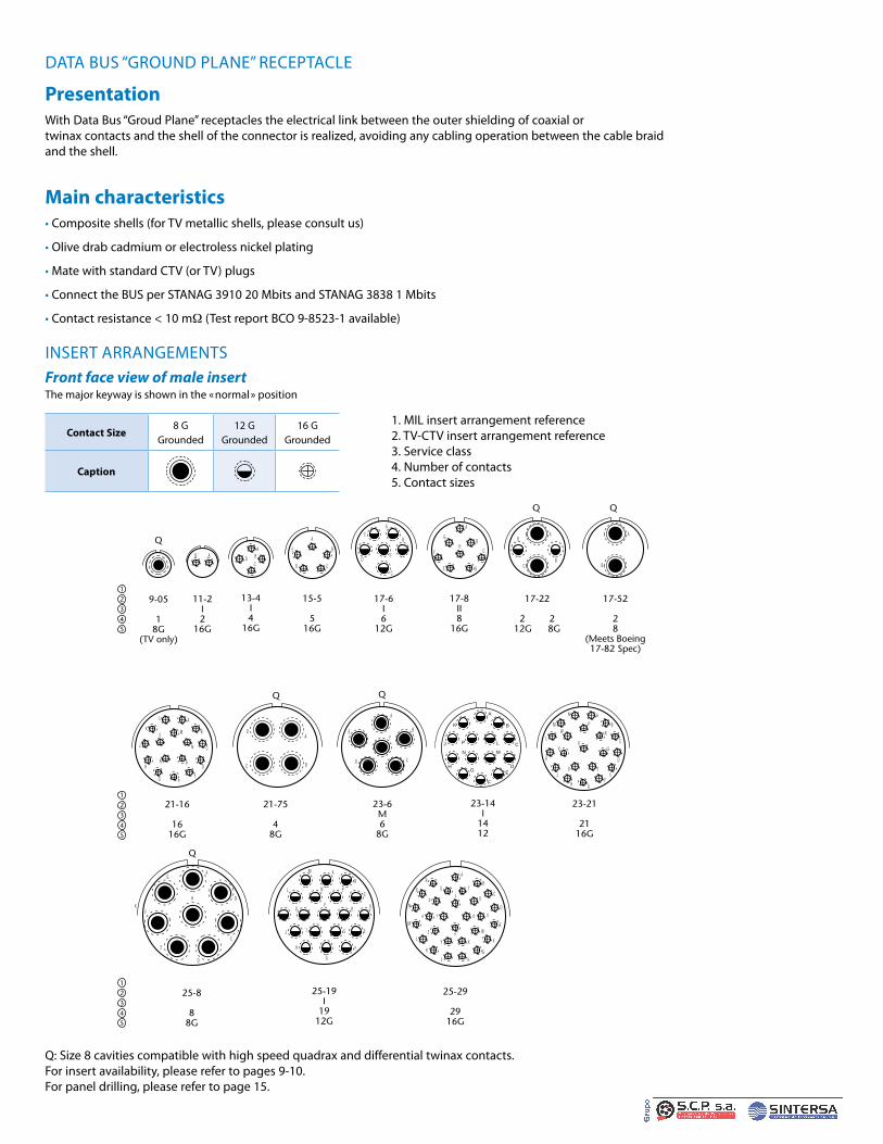
Amphenol Tri-Start™ TV-CTV
DATA BUS “GROUND PLANE” RECEPTACLE
PresentationWith Data Bus “Groud Plane” receptacles the electrical link between the outer shielding of coaxial or twinax contacts and the shell of the connector is realized, avoiding any cabling operation between the cable braid and the shell .
Main characteristics• Composite shells (for TV metallic shells, please consult us)
• Olive drab cadmium or electroless nickel plating
• Mate with standard CTV (or TV) plugs
• Connect the BUS per STANAG 3910 20 Mbits and STANAG 3838 1 Mbits
• Contact resistance < 10 mΩ (Test report BCO 9-8523-1 available)
INSERT ARRANGEMENTSFront face view of male insertThe major keyway is shown in the «normal» position
9-05
18G
(TV only)
123
45
123
45
123
45
11-2I2
16G
AB
13-4I4
16G
AB
CD
15-5
516G
A
B
CD
E
17-6I6
12G
A
B
C
D
E
F
17-8II8
16G
A
B
C
DE
F
G
H
17-22
2 2 12G 8G
A
BC
D
17-52
28
(Meets Boeing17-82 Spec)
A
B
21-16
1616G
A
B
C
D
EFG
H
J
K
L
M
N
PR
S
21-75
48G
A
BC
D
23-6M6
8G
A
B
C
F
D
E
25-8
88G
A
B
C
D
E
F
G
H
25-19I
1912G
A
B
C
D
E
F
G
H
J
K
L
M
N P
R
ST
UV
A
B
C
D
E
F
G
HJ
K
L
M
N
P
R
S
b
a
Z
Y X
W
V
U
T
df
e
c
25-29
2916G
23-21
2116G
A
B
C
D
EF
GH
J
K
L
M
N
P
R
S
TU
V
W
X
Q
Q Q
Q
Q Q
23-14I
1412
A
BK
CJ LP
MN
DHEG
F
Q: Size 8 cavities compatible with high speed quadrax and differential twinax contacts .For insert availability, please refer to pages 9-10 .For panel drilling, please refer to page 15 .
Contact Size8 G
Grounded12 G
Grounded16 G
Grounded
Caption
1 . MIL insert arrangement reference2 . TV-CTV insert arrangement reference3 . Service class4 . Number of contacts5 . Contact sizes

Amphenol Tri-Start™ TV-CTV
Tri-Start™ TV-CTV
S
R1
R2
T
SR1R2
2.36 +0.15 0
B
6.35 MAXV
R3
R4
Ø Y
4 Ø W
Panel drilling
0.13 M
TT0.13 M
23.19+0.28 0
TVS-Y / TVS-YN HERMETIC RECEPTACLES
PresentationHermetic receptacles TVS-Y and TVS-YN are used in applications which require the maintenance of pressure in the shell or box and in equipments imposing reduce bulk at the rear of connectors .
Main characteristics• 9 shell sizes (stainless steel)
• Solder pin contacts in nickel alloy
• Contact plating in active zone: Gold
• Glass insert
• Air leakage < 1 .10 -7 cm3/s under 1 bar of pressure differential
• Passivation or nickel plating
Overall dimensions - Hermetic versionsTVPs02Y JD38999/21Y
TVPs02YN JD38999/21N
Square flange receptacle
Shell size Bthread
Class 2A0.1P-0.3L-TS
(inches)
R1
(mm)R2
(mm)
S±0 .25
(mm)
T+0 .20-0 .13
(mm)
TT+0 .20-0 .13
(mm)
ØW+0
-0 .25(mm)
R3
(mm)R4
(mm)
VMini(mm)
ØYMini(mm)MIL-DTL-38999
Series IIIAmphenol
Socapex
A 9 .6250 18 .26 15 .09 23 .83 3 .25 5 .49 3 .25 18 .26 15 .09 24 .60 16 .66B 11 .7500 20 .62 18 .26 26 .19 3 .25 4 .93 3 .25 20 .62 18 .26 27 .00 20 .22C 13 .8750 23 .01 20 .62 28 .58 3 .25 4 .93 3 .25 23 .01 20 .62 31 .50 23 .42D 15 1 .0000 24 .61 23 .01 30 .96 3 .25 4 .39 3 .25 24 .61 23 .01 34 .50 26 .59E 17 1 .1875 26 .97 24 .61 33 .32 3 .25 4 .93 3 .25 26 .97 24 .61 28 .00 30 .96F 19 1 .2500 29 .36 26 .97 36 .53 3 .25 4 .93 3 .25 29 .36 26 .97 40 .50 32 .94G 21 1 .3750 31 .75 29 .36 39 .67 3 .25 4 .93 3 .25 31 .75 29 .36 44 .00 36 .12H 23 1 .5000 34 .93 31 .75 42 .88 3 .91 6 .15 3 .81 34 .93 31 .75 47 .00 39 .29J 25 1 .6250 38 .10 34 .93 46 .02 3 .91 6 .15 3 .81 38 .10 34 .93 50 .00 42 .47

Amphenol Tri-Start™ TV-CTV
Shell size Bthread
Class 2A0.1P-0.3L-TS
(inches)
ØGG+0 .28-0 .25
(mm)
ØKK+0 .03-0 .13
(mm)
L+0 .28
-0(mm)
M+0 .15-0 .13
(mm)
VMini(mm)
ØYMini(mm)MIL-DTL-38999
Series IIIAmphenol
Socapex
A 9 .6250 19 .05 17 .07 20 .47 3 .18 24 .60 17 .60B 11 .7500 21 .44 19 .84 20 .47 3 .18 27 .00 20 .40C 13 .8750 24 .61 23 .01 20 .47 3 .18 31 .50 23 .50D 15 1 .0000 27 .79 26 .19 20 .47 3 .18 24 .50 26 .70E 17 1 .1875 30 .94 29 .36 20 .47 3 .18 38 .00 29 .90F 19 1 .2500 33 .32 31 .75 20 .47 3 .18 40 .50 32 .30G 21 1 .3750 36 .53 34 .93 20 .47 3 .18 44 .00 35 .50H 23 1 .5000 39 .70 38 .10 21 .29 3 .96 47 .00 38 .60J 25 1 .6250 42 .88 41 .28 21 .29 3 .96 50 .00 41 .80
C
SH
Ø KK
K REF 5.08 MAXB
1.57 MINI3.18 MAX
LPanel drilling
Ø Y
Z
V
L
0.79 +0.15–0.13
B9.53 MAX
M
Ø KK
Ø GG
V
Panel drilling
Ø Y
V
TVs07Y JD38999/23YTVs07YN JD38999/23NJam nut receptacle
TVsIY JD38999/25YTVsIYN JD38999/25NSolder mounting receptacle
Shell size Bthread
Class 2A0.1P-0.3L-TS
(inches)
CMaxi(mm)
H/plats+0 .043-0 .41
(mm)
LMaxi(mm)
ØKK+0 .28
0(mm)
B±0 .25
(mm)
VMini(mm)
ØYMini(mm)
Z+0
-0 .25(mm)
Hex nutmax torquevalue N.mMIL-DTL-38999
Series IIIAmphenol
Socapex
A 9 .6250 30 .45 22 .23 9 .07 16 .31 26 .97 27 .80 17 .70 16 .99 4 .1B 11 .7500 35 .20 25 .40 9 .07 19 .46 31 .75 32 .60 20 .88 19 .53 5 .3C 13 .8750 38 .38 30 .18 9 .07 22 .66 34 .93 36 .00 25 .58 24 .26 6 .9D 15 1 .0000 41 .55 33 .32 9 .07 25 .86 38 .10 39 .60 28 .80 27 .53 8 .6E 17 1 .1875 44 .73 36 .53 9 .07 29 .01 41 .28 43 .30 31 .98 30 .68 9 .8F 19 1 .2500 49 .50 39 .67 9 .68 32 .21 46 .02 47 .00 35 .16 33 .86 10 .9G 21 1 .3750 52 .65 42 .80 9 .68 35 .36 49 .23 50 .60 38 .28 37 .06 12 .7H 23 1 .5000 65 .85 46 .02 9 .68 38 .56 52 .37 54 .20 41 .50 40 .01 13 .8J 25 1 .6250 59 .00 50 .80 9 .68 41 .71 55 .58 59 .70 44 .68 43 .41 15

Amphenol Tri-Start™ TV-CTV
Tri-Start™ TV-CTV
58.5 MAX
51 MAX
3.2 MAX
6.3 RAD
42.4 MAX
LENGTH "X"See chart A
7.11 MAX
Ø42.5 MAXACCESSORY
LANYARD RELEASE PLUGS
PresentationLanyard release plugs meet the requirements of the standard MIL-DTL-38999 III standard, as well as the specific MIL-STD-1760 version that also meets MIL-STD-1760 and STANAG 3837 AA .
2 insert arrangements are available in MIL-STD-1760 lanyard release plugs, in accordance with the definition of BUS 1553 B standards in N coding (arrangement 25-20) and in A coding (arrangement 25-11) - Refer to pages 7 to 8 - insert arrangements marked with***
Other shell sizes and insert arrangements are also available in the MIL-DTL-38999 standard version . Please refer to pages 6 to 8 and consult us for further information .
Main characteristics• Lanyard release plugs mate with standard TV receptacles, JD38999/20 and /24 types
• They accept MIL-C-85049 accessories
• They are 100% scoop-proof
• Applications: - Quick disconnect- Weapon systems- Ejector seats
Overall dimensionsLanyard release plugs - MIL-STD-1760
Low profile version (ordering information on page 30)
TVFBRW JD38999/31W
Lanyard release plugs - MIL-STD-1760
CHART A
Other lengths are also available under TVFBRW proprietary designation . Consult us .
Length "X" MIL.STD 1760 coding mm
D 140E 153F 166G 178H 191J 407k 229M 254X 432

Amphenol Tri-Start™ TV-CTV
Blue band
9.12 Max9.50 Max
45.24 Max60.33 Max
Length XSee chart II
Ø 12.70 ± 0.79D
MetricV Thread
B
Lanyard release plugs
Standard version(ordering information page 31)
885565...P JD38999/29W915565...P JD38999/29F885565...s JD38999/30W915565...s JD38999/30F
CHART I
CHART III
CHART II
Length "X" (mm) Code MS/Amphenol
102 A115 B127 C140 D153 E166 F178 G191 H203 I216 J229 k242 L254 M267 N280 P293 R305 S318 T331 U356 V381 W407 X432 Y458 z
Arrangement code Insert arrangement
04 11-406 11-3507 11-9810 13-411 13-813 13-9814 13-3518 15-519 15-1920 15-3527 17-628 17-829 17-2630 17-3531 17-9937 19-1138 19-2839 19-3240 19-3547 21-1148 21-1649 21-3550 21-4151 21-3957 23-2158 23-3559 23-5366 25-1967 25-2968 25-3569 25-4370 25-6171 25-472 25-24
Shell sizeMetric Max
BMax
(mm)
DMax
(mm)MIL-DTL-38999Series III
AmphenolSocapex
B 11 M15X1 .0-6G 46 .89 28 .17C 13 M18x1 .0-6g 50 .09 31 .75D 15 M22X1 .0-6G 52 .81 34 .93E 17 M25X1 .0-6G 56 .01 38 .10F 19 M28X1 .0-6G 58 .45 41 .28G 21 M31X1 .0-6G 62 .79 44 .45H 23 M34X1 .0-6G 65 .89 47 .63J 25 M37X1 .0-6G 68 .71 50 .08