Amphenol Tri-Start Subminiature Cylindrical Connectors high current discharge events (see page 51)...
54
12-092-14 MIL-DTL-38999, Series III • Aluminum • Stainless Steel/Firewall • Composite • Clutch-Lok ® High Vibration Amphenol Tri-Start Subminiature Cylindrical Connectors ® TM
Transcript of Amphenol Tri-Start Subminiature Cylindrical Connectors high current discharge events (see page 51)...
12-092-14
Amphenol CorporationAmphenol Aerospace40-60 Delaware AvenueSidney, New York 13838-1395Phone: 800-678-0141 or 607-563-5011www.amphenol-aerospace.com
MIL-DTL-38999, Series III• Aluminum• Stainless Steel/Firewall• Composite• Clutch-Lok® High Vibration
Amphenol Tri-StartSubminiature Cylindrical Connectors
® TM
Table of Contents Page No.
Series III - The Highest Performance MIL-DTL-38999 Connector ...................... 1Tri-Start Series III Versatility and Options ........................................................... 2Shell Styles and Key Design Features ............................................................... 3Test Data .......................................................................................................... 4Specifications .................................................................................................... 5Insert Availability and Identification ................................................................ 6, 7Alternate Positioning .......................................................................................... 8Insert Arrangements ................................................................................... 9-15Crimp
TVP00R/CTVP00R Wall Mounting Receptacle .......................................... 16TVP02R/CTVP02R Box Mounting Receptacle .......................................... 17TV06R/CTV06R Straight Plug ................................................................... 18TV26/MTV26 CLUTCH-LOK® Straight Plug .............................................. 19TV07R/CTV07R Jam Nut Receptacle ....................................................... 20TV01R/CTV01R Line Receptacle .............................................................. 21TV09R Flange Mounting Plug .................................................................... 22
HermeticTVPS02Y Box Mounting Receptacle ......................................................... 23TVS07Y Jam Nut Receptacle ................................................................... 24TVSIY Solder Mounting Receptacle .......................................................... 25TVSHIY Weld Mounting Recepacle ........................................................... 26
Fail Safe, Lanyard ReleaseDesign Features, Types ............................................................................ 27D38999/29, D38999/30 Lanyard Release Plug ..................................... 28-30D38999/31 TV Fail Safe Lanyard Release Plug for MIL-STD-1760 ....... 31, 32Accessories for Lanyard Release Connectors .......................................... 33
AccessoriesReceptacle Protection Caps ..................................................................... 34Plug Protection Caps ................................................................................ 35Dummy Receptacles ................................................................................ 36Cable Clamps ........................................................................................... 37Universal Header Assembly for Flex Print or PC Board Connectors .... 38, 39
Contacts, Sealing Plugs, Plastic/Metal Protection Caps ................................... 40Contacts (Printed Circuit Board, Wire wrap) .................................................... 41Application Tools .............................................................................................. 42How to Order
Amphenol® TV, Metal and Amphenol® TV26 CLUTCH-LOK® ................... 43D38999, TV Military, Metal and MTV26 CLUTCH-LOK® ............................ 44Amphenol® CTV, Composite ..................................................................... 45D38999, CTV Military, Composite .............................................................. 46
Composite Weight Comparisons ..................................................................... 47Specials (Fiber Optics, Filter Protection, Flex Assemblies,
PCB Applications) ..................................................................................... 48Specials (Coax, Twinax, Triax Contacts, Ground Plane Connectors,
Press Fit Connectors) ............................................................................. 49Specials (Quadrax Contacts) ......................................................................... 50Specials (Deep Reach Shells, Stand-off Flange Shells, Connectors with
Integral Strain Reliefs, ESD Protection, RJ Field Connectors .................. 51Sales Office and Distributor Listing ................................................................ 52
For additional information concerning Amphenol Tri-Start Connectors, or if thereare special application requirements, contact your local sales office or
Amphenol Aerospace40-60 Delaware Ave.Sidney, New York 13838-1395Phone: 607-563-5011 Fax: 607-563-5157www.amphenol-aerospace.com
Amphenol Aerospace is a Certified ISO9001 Manufacturer.
1
Amphenol® Tri-StartSeries III - the highest performanceMIL-DTL-38999 connector
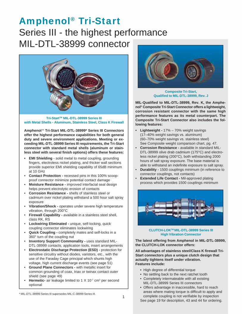
Tri-StartTM MIL-DTL-38999 Series IIIwith Metal Shells - Aluminum, Stainless Steel, Class K Firewall
Composite Tri-Start,Qualified to MIL-DTL-38999, Rev. J
Amphenol ® Tri-Start MIL-DTL-38999* Series III Connectorsoffer the highest performance capabilities for both generalduty and severe environment applications. Meeting or ex-ceeding MIL-DTL-38999 Series III requirements, the Tri-Startconnector with standard metal shells (aluminum or stain-less steel with several finish options) offers these features:
• EMI Shielding - solid metal to metal coupling, groundingfingers, electroless nickel plating, and thicker wall sectionsprovide superior EMI shielding capability of 65dB minimumat 10 GHz
• Contact Protection - recessed pins in this 100% scoop-proof connector minimize potential contact damage
• Moisture Resistance - improved interfacial seal designhelps prevent electrolytic erosion of contacts
• Corrosion Resistance - shells of stainless steel orcadmium over nickel plating withstand a 500 hour salt sprayexposure
• Vibration/Shock - operates under severe high temperaturevibration, through 200°C
• Firewall Capability - available in a stainless steel shell,class RK, RS
• Lockwiring Eliminated - unique, self-locking, quickcoupling connector eliminates lockwiring
• Quick Coupling - completely mates and self-locks in a360° turn of the coupling nut
• Inventory Support Commonality - uses standard MIL-DTL-38999 contacts, application tools, insert arrangements
• Electrostatic Discharge Protection (ESD) - protection forsensitive circuitry without diodes, varistors, etc., with theuse of the Faraday Cage principal which shunts highvoltage, high current discharge events (see page 51)
• Ground Plane Connectors - with metallic insert forcommon grounding of coax, triax or twinax contact outershield (see page 49)
• Hermetic- air leakage limited to 1 X 10⁻⁷ cm3 per secondoptional
MIL-Qualified to MIL-DTL-38999, Rev. K, the Amphe-nol® Composite Tri-Start Connector offers a lightweight,corrosion resistant connector with the same highperformance features as its metal counterpart. TheComposite Tri-Start Connector also includes the fol-lowing features:
• Lightweight - 17% – 70% weight savings(17–40% weight savings vs. aluminum)(60–70% weight savings vs. stainless steel)See Composite weight comparison chart, pg. 47.
• Corrosion Resistance - available in standard MIL-DTL-38999 olive drab cadmium (175°C) and electro-less nickel plating (200°C), both withstanding 2000hours of salt spray exposure. The base material isable to withstand an indefinite exposure to salt spray.
• Durability - 1500 couplings minimum (in reference toconnector couplings, not contacts)
• Extended Life Contact - Mil-approved platingprocess which provides 1500 couplings minimum
The latest offering from Amphenol in MIL-DTL-38999,the CLUTCH-LOK connector offers:
All advantages of stainless steel/Class K firewall Tri-Start connectors plus a unique clutch design thatactually tightens itself under vibration.Features include:
• High degree of differential torque• No settling back to the next ratchet tooth• Completely intermateable with all existing MIL-DTL-38999 Series III connectors• Offers advantage in inaccessible, hard to reach areas where mating torque is difficult to apply and complete coupling is not verifiable by inspectionSee page 19 for description, 43 and 44 for ordering.
CLUTCH-LOKTM MIL-DTL-38999 Series IIIHigh Vibration Connector
* MIL-DTL-38999 Series III supersedes MIL-C-38999 Series III.
2
Amphenol® Tri-Startoffers more versatility & optionsthan any other interconnection family
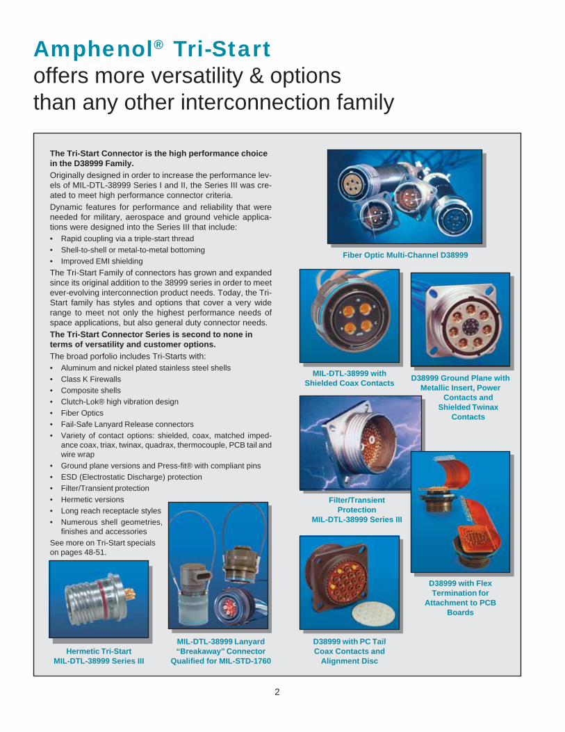
Fiber Optic Multi-Channel D38999
Filter/TransientProtection
MIL-DTL-38999 Series III
D38999 Ground Plane withMetallic Insert, Power
Contacts andShielded Twinax
Contacts
MIL-DTL-38999 withShielded Coax Contacts
D38999 with PC TailCoax Contacts and
Alignment Disc
D38999 with FlexTermination for
Attachment to PCBBoards
MIL-DTL-38999 Lanyard“Breakaway” Connector
Qualified for MIL-STD-1760Hermetic Tri-Start
MIL-DTL-38999 Series III
The Tri-Start Connector is the high performance choicein the D38999 Family.Originally designed in order to increase the performance lev-els of MIL-DTL-38999 Series I and II, the Series III was cre-ated to meet high performance connector criteria.Dynamic features for performance and reliability that wereneeded for military, aerospace and ground vehicle applica-tions were designed into the Series III that include:• Rapid coupling via a triple-start thread• Shell-to-shell or metal-to-metal bottoming• Improved EMI shielding
The Tri-Start Family of connectors has grown and expandedsince its original addition to the 38999 series in order to meetever-evolving interconnection product needs. Today, the Tri-Start family has styles and options that cover a very widerange to meet not only the highest performance needs ofspace applications, but also general duty connector needs.The Tri-Start Connector Series is second to none interms of versatility and customer options.The broad porfolio includes Tri-Starts with:• Aluminum and nickel plated stainless steel shells• Class K Firewalls• Composite shells• Clutch-Lok® high vibration design• Fiber Optics• Fail-Safe Lanyard Release connectors• Variety of contact options: shielded, coax, matched imped-
ance coax, triax, twinax, quadrax, thermocouple, PCB tail andwire wrap
• Ground plane versions and Press-fit® with compliant pins• ESD (Electrostatic Discharge) protection• Filter/Transient protection• Hermetic versions• Long reach receptacle styles• Numerous shell geometries,
finishes and accessoriesSee more on Tri-Start specialson pages 48-51.
3
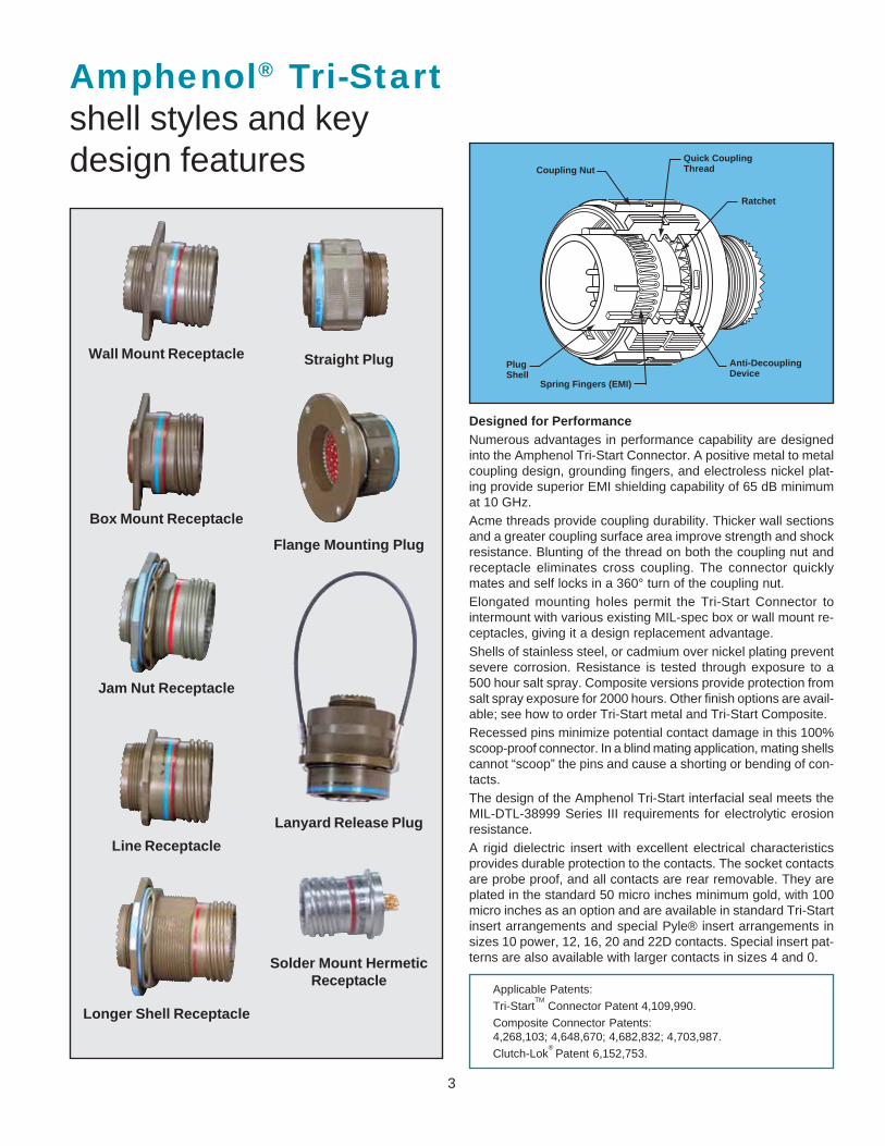
Quick Coupling�ThreadCoupling Nut
Plug�Shell
Spring Fingers (EMI)
Anti-Decoupling�Device
Ratchet
Amphenol® Tri-Startshell styles and keydesign features
Designed for PerformanceNumerous advantages in performance capability are designedinto the Amphenol Tri-Start Connector. A positive metal to metalcoupling design, grounding fingers, and electroless nickel plat-ing provide superior EMI shielding capability of 65 dB minimumat 10 GHz.Acme threads provide coupling durability. Thicker wall sectionsand a greater coupling surface area improve strength and shockresistance. Blunting of the thread on both the coupling nut andreceptacle eliminates cross coupling. The connector quicklymates and self locks in a 360° turn of the coupling nut.Elongated mounting holes permit the Tri-Start Connector tointermount with various existing MIL-spec box or wall mount re-ceptacles, giving it a design replacement advantage.Shells of stainless steel, or cadmium over nickel plating preventsevere corrosion. Resistance is tested through exposure to a500 hour salt spray. Composite versions provide protection fromsalt spray exposure for 2000 hours. Other finish options are avail-able; see how to order Tri-Start metal and Tri-Start Composite.Recessed pins minimize potential contact damage in this 100%scoop-proof connector. In a blind mating application, mating shellscannot “scoop” the pins and cause a shorting or bending of con-tacts.The design of the Amphenol Tri-Start interfacial seal meets theMIL-DTL-38999 Series III requirements for electrolytic erosionresistance.A rigid dielectric insert with excellent electrical characteristicsprovides durable protection to the contacts. The socket contactsare probe proof, and all contacts are rear removable. They areplated in the standard 50 micro inches minimum gold, with 100micro inches as an option and are available in standard Tri-Startinsert arrangements and special Pyle® insert arrangements insizes 10 power, 12, 16, 20 and 22D contacts. Special insert pat-terns are also available with larger contacts in sizes 4 and 0.
Wall Mount Receptacle
Box Mount Receptacle
Jam Nut Receptacle
Straight Plug
Flange Mounting Plug
Lanyard Release Plug
Line Receptacle
Longer Shell Receptacle
Solder Mount HermeticReceptacle
Applicable Patents:
Tri-StartTM
Connector Patent 4,109,990.
Composite Connector Patents:4,268,103; 4,648,670; 4,682,832; 4,703,987.
Clutch-Lok®
Patent 6,152,753.
4
Tri-Starttest data
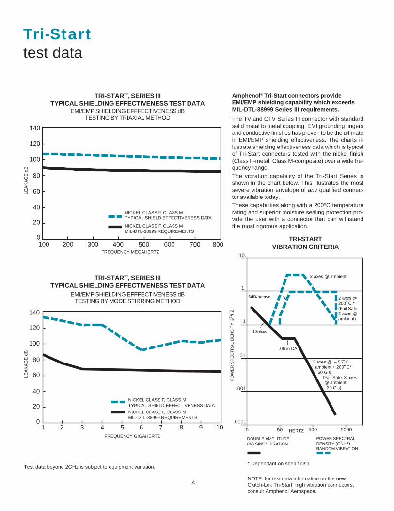
TRI-START, SERIES IIITYPICAL SHIELDING EFFECTIVENESS TEST DATA
EMI/EMP SHIELDING EFFFECTIVENESS dBTESTING BY TRIAXIAL METHOD
TRI-START, SERIES IIITYPICAL SHIELDING EFFECTIVENESS TEST DATA
EMI/EMP SHIELDING EFFFECTIVENESS dBTESTING BY MODE STIRRING METHOD
Test data beyond 2GHz is subject to equipment variation.* Dependant on shell finish
NOTE: for test data information on the newClutch-Lok Tri-Start, high vibration connectors,consult Amphenol Aerospace.
Amphenol® Tri-Start connectors provideEMI/EMP shielding capability which exceedsMIL-DTL-38999 Series III requirements.
The TV and CTV Series III connector with standardsolid metal to metal coupling, EMI grounding fingersand conductive finishes has proven to be the ultimatein EMI/EMP shielding effectiveness. The charts il-lustrate shielding effectiveness data which is typicalof Tri-Start connectors tested with the nickel finish(Class F-metal, Class M-composite) over a wide fre-quency range.The vibration capability of the Tri-Start Series isshown in the chart below. This illustrates the mostsevere vibration envelope of any qualified connec-tor available today.These capabilities along with a 200°C temperaturerating and superior moisture sealing protection pro-vide the user with a connector that can withstandthe most rigorous application.
TRI-STARTVIBRATION CRITERIA
140
120
100
80
60
40
20
0100 200 300 400 500 600 700 800
NICKEL CLASS F, CLASS M�TYPICAL SHIELD EFFECTIVENESS DATA
FREQUENCY MEGAHERTZ
NICKEL CLASS F, CLASS M�MIL-DTL-38999 REQUIREMENTS
LEA
KA
GE
dB
140
120
100
80
60
40
20
01 2 3 4 5
NICKEL CLASS F, CLASS M�TYPICAL SHIELD EFFECTIVENESS DATA�
NICKEL CLASS F, CLASS M�MIL-DTL-38999 REQUIREMENTS
6 7 8 9 10FREQUENCY GIGAHERTZ
LEA
KA
GE
dB
5 50 500 5000
.0001
.001
.01
.1
1.
10.
10in/sec
.06 in DA.
3 axes @ – 55 C� ambient + 200 C*� 60 G's� (Fail Safe: 3 axes�� @ ambient�� 30 G's)
��
�2 axes @�200 C *�(Fail Safe:�2 axes @�ambient)
2 axes @ ambient
6dB/octave
HERTZ
DOUBLE AMPLITUDE�(IN) SINE VIBRATION
POWER SPECTRAL�DENSITY (G2/HZ)�RANDOM VIBRATION
PO
WE
R S
PE
CT
RA
L D
EN
SIT
Y G
2 /HZ
��
˚�˚�
˚�
5
Suggested Oper. VoltageService (Sea Level) Test Voltage Test Voltage Test Voltage Test VoltageRating AC (RMS) DC (Sea Level) 50,000 Ft. 70,000 Ft. 110,000 Ft.
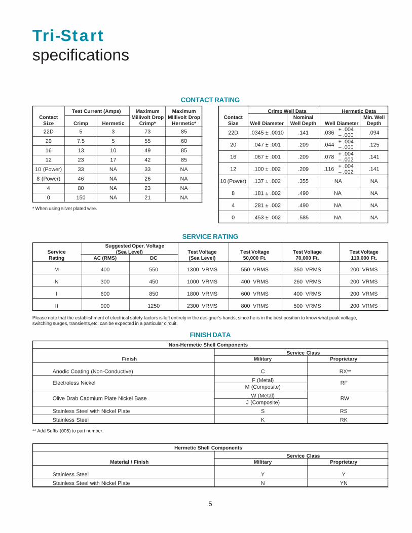
22D .0345 ± .0010 .141 .036 .094
20 .047 ± .001 .209 .044 .125
16 .067 ± .001 .209 .078 .141
12 .100 ± .002 .209 .116 .141
10 (Power) .137 ± .002 .355 NA NA
8 .181 ± .002 .490 NA NA
4 .281 ± .002 .490 NA NA
0 .453 ± .002 .585 NA NA
Test Current (Amps) Maximum MaximumContact Millivolt Drop MIllivolt Drop
Size Crimp Hermetic Crimp* Hermetic*
22D 5 3 73 85
20 7.5 5 55 60
16 13 10 49 85
12 23 17 42 85
10 (Power) 33 NA 33 NA
8 (Power) 46 NA 26 NA
4 80 NA 23 NA
0 150 NA 21 NA
CONTACT RATING
+ .004– .000+ .004– .000+ .004– .002+ .004– .002
M 400 550 1300 VRMS 550 VRMS 350 VRMS 200 VRMS
N 300 450 1000 VRMS 400 VRMS 260 VRMS 200 VRMS
I 600 850 1800 VRMS 600 VRMS 400 VRMS 200 VRMS
II 900 1250 2300 VRMS 800 VRMS 500 VRMS 200 VRMS
SERVICE RATING
FINISH DATANon-Hermetic Shell Components
Service ClassFinish Military Proprietary
Anodic Coating (Non-Conductive) C RX**
F (Metal)M (Composite)
W (Metal)J (Composite)
Stainless Steel with Nickel Plate S RS
Stainless Steel K RK
Stainless Steel Y Y
Stainless Steel with Nickel Plate N YN
Hermetic Shell Components
Service ClassMaterial / Finish Military Proprietary
* When using silver plated wire.
Crimp Well Data Hermetic DataContact Nominal Min. Well
Size Well Diameter Well Depth Well Diameter Depth
Tri-Startspecifications
** Add Suffix (005) to part number.
Olive Drab Cadmium Plate Nickel Base
RF
RW
Electroless Nickel
Please note that the establishment of electrical safety factors is left entirely in the designer’s hands, since he is in the best position to know what peak voltage,switching surges, transients,etc. can be expected in a particular circuit.
6
Tri-Startinsert availability and identification
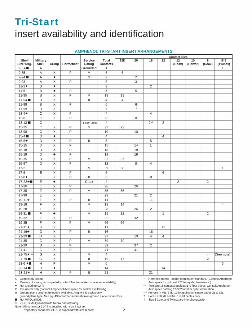
AMPHENOL TRI-START INSERT ARRANGEMENTSContact Size
Shell Military Service Total 22D 20 16 12 12 10 8 8††Size/Arrg. Shell Crimp Hermetics* Rating Contacts (Coax) (Power) (Coax) (Twinax)9-5★■ A Grounded 1 19-35 A X P M 6 69-94 ■ A ✦ M 2 29-98 A X P I 3 311-2★ B ✦ I 2 211-5 B ✦ P I 5 511-35 B X P M 13 1311-54 ■ B X II 4 411-98 B X P I 6 611-99 B X I 7 713-4★ C X P I 4 413-8 C X P I 8 813-13 ■ C I, Fiber Optic 4 2** 213-35 C X P M 22 2213-98 C X P I 10 1015-4 ■ D ✦ I 4 415-5★ D X P II 5 515-15 D X P I 15 14 115-18 D X P I 18 1815-19 D ✦ P I 19 1915-35 D X P M 37 3715-97 D X P I 12 8 417-2 E X M 39 38 117-6 E X P I 6 617-8★ E X P II 8 817-22★■ E ✦ Coax 4 2 217-26 E X P I 26 2617-35 E X P M 55 5517-99 E X I 23 21 219-11★ F X P II 11 1119-18 F X M 18 14 419-28 F X I 28 26 219-31 ■ F ✦ M 15 12 1 219-32 F X P I 32 3219-35 F X P M 66 6621-11★ G X I 11 1121-16★ G X P II 16 1621-29 ■ G X I 27 19 4 421-35 G X P M 79 7921-39 G X P I 39 37 221-41 G X P I 41 4121-75★ ✧ G X M 4 4 (See note)21-79 ■ G X II 19 17 223-6 ★■ H P M 6 623-14 ■ H ✦ I 14 1423-21★ H X P II 21 21
X Completely tooled.• Majority of tooling is completed (contact Amphenol Aerospace for availabilty).✦ Not tooled for 02-R.P Pin inserts only (contact Amphenol Aerospace for socket availability).★ Ground plane proprietary option available. Arrg. 9-5 is exclusively
ground plane type. See pg. 49 for further information on ground plane connectors.■ Not Mil-Qualified.✧ 21-75 is Mil-Qualified with twinax contacts only.Note: MS connector 21-75 is supplied with size 8 twinax.
Proprietary connector 21-75 is supplied with size 8 coax.
* Hermetic inserts - solder termination standard. (Contact AmphenolAerospace for optional PCB or eyelet termination).
** Two size 16 contacts dedicated to fiber optics. Consult AmphenolAerospace catalog 12-352 for fiber optic information.
*** For use in MIL-STD-1760 applications (see pages 31 & 32).† For RG 180/U and RG 195/U cables only.†† Size 8 Coax and Twinax are interchangeable.
7
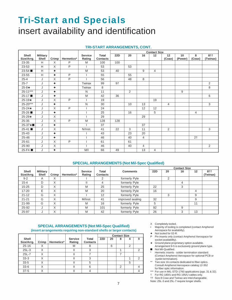
Tri-Start and Specialsinsert availability and identification
Contact SizeShell Military Service Total 22D 20 16 12 12 10 8 8††
Size/Arrg. Shell Crimp Hermetics* Rating Contacts (Coax) (Power) (Coax) (Twinax)23-35 H X P M 100 10023-53 H X P I 53 5323-54 ■ H ✦ M 53 40 9 423-55 H ✦ P I 55 5525-4 J X P I 56 48 825-7 J ✦ Twinax 99 97 225-8★ J ✦ Twinax 8 825-11*** J ✦ N 11 2 925-17 ■ J ✦ M 42 36 625-19★ J X P I 19 1925-20*** J ✦ N 30 10 13 4 325-24★ J X P I 24 12 1225-26 ■ J ✦ I 25 16 5 425-29★ J X I 29 2925-35 J X P M 128 12825-37★■ J ✦ I 37 3725-41 ■ J X N/Inst. 41 22 3 11 2 325-43 J ✦ I 43 23 2025-46 J ✦ I 46 40 4 2†25-61 J X P I 61 6125-90 J X I 46 40 4 225-F4 ■ J ✦ M/I 66 49 13 4
TRI-START ARRANGEMENTS, CONT.
Contact SizeShell Military Service Total Comments 22D 20 16 12 8††
Size/Arrg. Shell Crimp Hermetics* Rating Contacts (Twinax) 9-2 A X I 2 formerly Pyle 215-4 D X II 4 formerly Pyle 415-25 D X M 25 formerly Pyle 22 317-20 E X M 20 formerly Pyle 16 421-12 G X I 12 formerly Pyle 3 921-21 G X M/Inst. 41 improved sealing 32 921-99 G X M 16 formerly Pyle 5 1125-92 J X M 101 formerly Pyle 92 925-97 J X M 42 formerly Pyle 26 3 13
SPECIAL ARRANGEMENTS (Not Mil-Spec Qualified)
Contact SizeShell Service Total 22D 20 8 4 0
Size/Arrg. Crimp Hermetics* Rating Contacts25-16 X M 8 6 225L-3 X II 3 1 225L-7 X II 7 733-3 X II 3 1 233-5 X II 5 533-6 X II 6 2 437-5 X II 4 4
SPECIAL ARRANGEMENTS (Not Mil-Spec Qualified)(insert arrangements requiring non-standard shells or larger contacts)
X Completely tooled.• Majority of tooling is completed (contact Amphenol
Aerospace for availabilty).✦ Not tooled for 02-R.P Pin inserts only (contact Amphenol Aerospace for
socket availability).★ Ground plane proprietary option available.
Arrangement 9-5 is exclusively ground plane type.■ Not Mil-Qualified.* Hermetic inserts - solder termination standard.
(Contact Amphenol Aerospace for optional PCB or eyelet termination).
** Two size 16 contacts dedicated to fiber optics.Consult Amphenol Aerospace catalog 12-352for fiber optic information.
*** For use in MIL-STD-1760 applications (pgs. 31 & 32).† For RG 180/U and RG 195/U cables only.†† Size 8 Coax and Twinax are interchangeable.Note: 25L-3 and 25L-7 require longer shells.
8
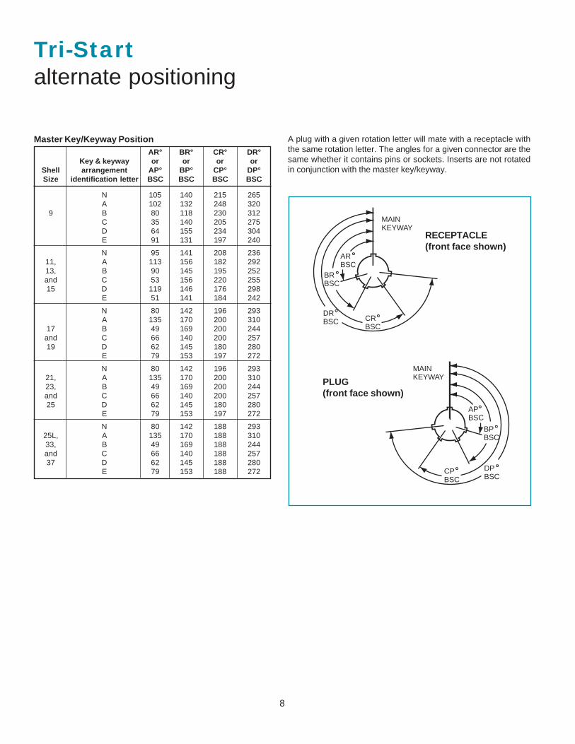
Tri-Startalternate positioning
AR° BR° CR° DR°Key & keyway or or or or
Shell arrangement AP° BP° CP° DP°Size identification letter BSC BSC BSC BSC
N 105 140 215 265A 102 132 248 320
9 B 80 118 230 312C 35 140 205 275D 64 155 234 304E 91 131 197 240
N 95 141 208 23611, A 113 156 182 29213, B 90 145 195 252and C 53 156 220 25515 D 119 146 176 298
E 51 141 184 242
N 80 142 196 293A 135 170 200 310
17 B 49 169 200 244and C 66 140 200 25719 D 62 145 180 280
E 79 153 197 272
N 80 142 196 29321, A 135 170 200 31023, B 49 169 200 244and C 66 140 200 25725 D 62 145 180 280
E 79 153 197 272
N 80 142 188 29325L, A 135 170 188 31033, B 49 169 188 244and C 66 140 188 25737 D 62 145 188 280
E 79 153 188 272
Master Key/Keyway Position A plug with a given rotation letter will mate with a receptacle withthe same rotation letter. The angles for a given connector are thesame whether it contains pins or sockets. Inserts are not rotatedin conjunction with the master key/keyway.
PLUG(front face shown)
RECEPTACLE(front face shown)
MAIN�KEYWAY
AP�BSC
BP�BSC
DP�BSC
CP�BSC
˚�
˚�
˚�˚�
DR�BSC̊� CR�
BSC̊�
BR�BSC̊�
AR�BSC̊�
MAIN�KEYWAY
9 CONTACT LEGEND
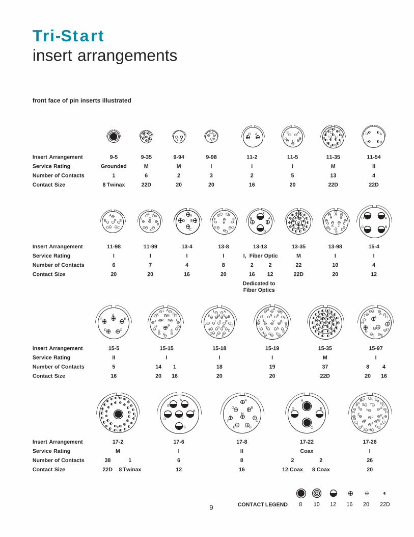
Tri-Startinsert arrangements
front face of pin inserts illustrated
Insert Arrangement 9-5 9-35 9-94 9-98 11-2 11-5 11-35 11-54
Service Rating Grounded M M I I I M II
Number of Contacts 1 6 2 3 2 5 13 4
Contact Size 8 Twinax 22D 20 20 16 20 22D 22D
Insert Arrangement 11-98 11-99 13-4 13-8 13-13 13-35 13-98 15-4
Service Rating I I I I I, Fiber Optic M I I
Number of Contacts 6 7 4 8 2 2 22 10 4
Contact Size 20 20 16 20 16 12 22D 20 12
Dedicated to Fiber Optics
Insert Arrangement 15-5 15-15 15-18 15-19 15-35 15-97
Service Rating II I I I M I
Number of Contacts 5 14 1 18 19 37 8 4
Contact Size 16 20 16 20 20 22D 20 16
Insert Arrangement 17-2 17-6 17-8 17-22 17-26
Service Rating M I II Coax I
Number of Contacts 38 1 6 8 2 2 26
Contact Size 22D 8 Twinax 12 16 12 Coax 8 Coax 20
A
B
CD
E
FG
5 164
32
B A
AB A
BC
D
E1
2
3
456
7
8
91011
1213
A
B
CD
E F
A
B
C
D
AB
CD
E
FG
HAB
C
D
1
2122
AB
C
DE
F
G
H
JK
A
BC
D
AB
CD
E
AB
C
DE
FG
H
J
KL
MN
P
R
A
B
C
D
EFG
H
J
KL
M N
P
RS
T U
AB
C
D
EFGH
J
K
LM
N P
R
ST
U V
1
2131A
BC
D
EFG
H
JK
L
M
1
6
11
17
30
A
B
C
D
E
F
A
B
C
DE
F
G
H
A
D
C
B
AB
C
D
E
FGHJ
KL
M
N
P
RS T
U
V
WX
Y
Z
ab
c
8 10 12 16 20 22D
CA
B
A�
B�
D�
C�
10
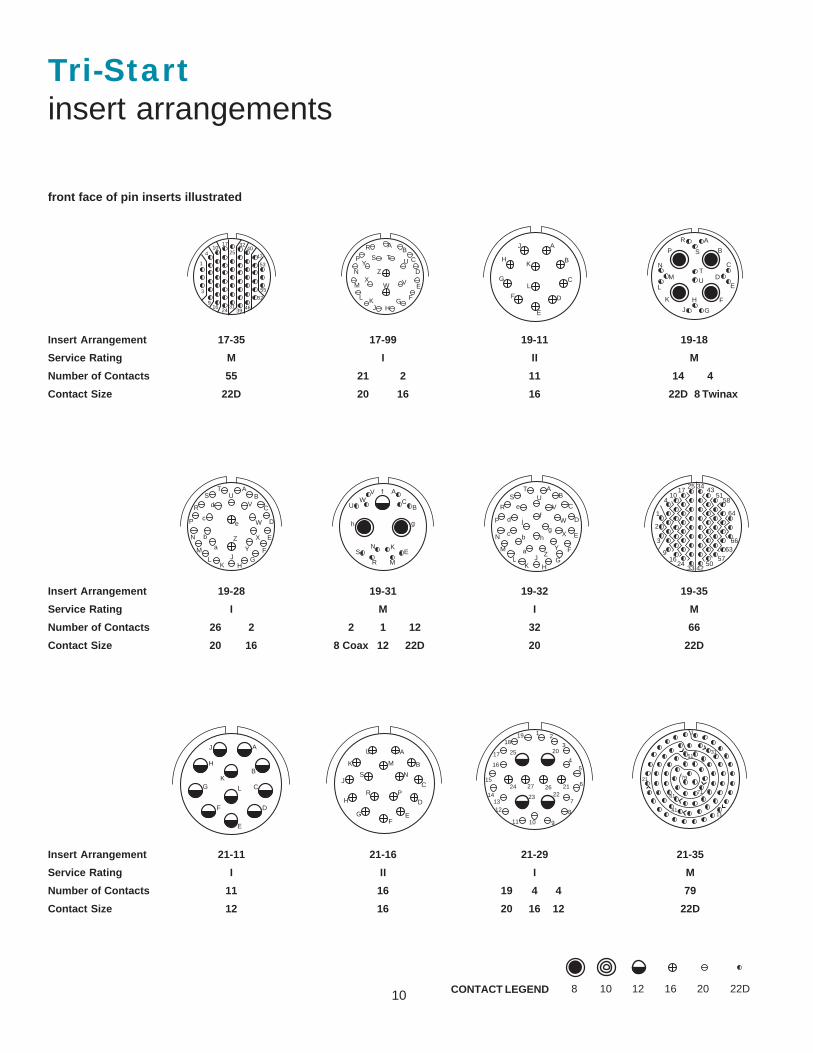
Tri-Startinsert arrangements
Insert Arrangement 17-35 17-99 19-11 19-18
Service Rating M I II M
Number of Contacts 55 21 2 11 14 4
Contact Size 22D 20 16 16 22D 8 Twinax
Insert Arrangement 19-28 19-31 19-32 19-35
Service Rating I M I M
Number of Contacts 26 2 2 1 12 32 66
Contact Size 20 16 8 Coax 12 22D 20 22D
Insert Arrangement 21-11 21-16 21-29 21-35
Service Rating I II I M
Number of Contacts 11 16 19 4 4 79
Contact Size 12 16 20 16 12 22D
CONTACT LEGEND
front face of pin inserts illustrated
1
3
4
9
10
16
17
24
25
31
32
39
40
47
46
52
53
55
AB
C
D
E
FGHJ
KL
M
N
P
R
S TU
VWX
YZ
A
B
C
D
E
F
G
H
J
K
L
AB
C
D
E
FG
H
R
JK
LM
N
P
ST
UV
W
X
Y
Za
b
c
d
e
A
BC
EK
M
N
R
S
U
VW
gh
f AB
C
D
E
F
GH
JK
L
M
N
P
R
ST
UV
W
X
YZa
bc
d
ef
gh
j1
2
3
4
9
10
16
17
24
25
33
34
42
43
50
51
57
58
63
64
66
A
B
C
D
E
F
G
H
J
K
L
A
B
C
D
EF
G
H
J
K
L
M
N
PR
S
1 2
3
45
6
7
8
91011
1213
14
15
16
17
1819
20
2122
24
23
25
2627
1
11
21
31
41
51
6171
79
8 10 12 16 20 22D
A
B
C
DE
F
G
H
J
K
L
M
N
P
R
S
T
U
11 CONTACT LEGEND
Tri-Startinsert arrangements
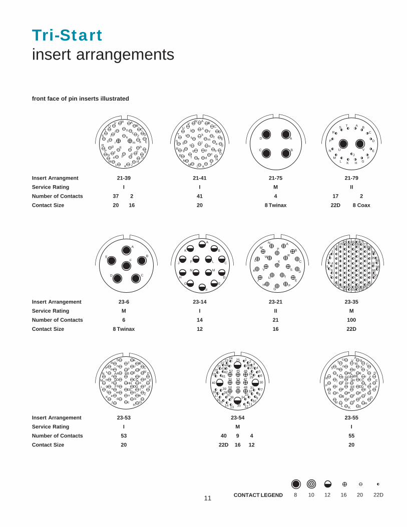
Insert Arrangment 21-39 21-41 21-75 21-79
Service Rating I I M II
Number of Contacts 37 2 41 4 17 2
Contact Size 20 16 20 8 Twinax 22D 8 Coax
Insert Arrangement 23-6 23-14 23-21 23-35
Service Rating M I II M
Number of Contacts 6 14 21 100
Contact Size 8 Twinax 12 16 22D
front face of pin inserts illustrated
Insert Arrangement 23-53 23-54 23-55
Service Rating I M I
Number of Contacts 53 40 9 4 55
Contact Size 20 22D 16 12 20
AB
C
D
E
F
GH
JKLM
NP
R
S
TU
V W
XY
Z
a
bc
de
f
gh
ij
k
mn
p
qr
AB
C
D
E
F
G
HJ
KLMN
P
R
S
T
UV
W
XY
Z
a
bc
def
g
h
i
jk
m
npq
r
s
tA
BC
D
AT BS
CR
DP
EN
M FL GHK
J
VU
A
B
CD
EF
A
BK
CJ LP
MN
DH
EG
F
A
B
C
D
E
FG
HJ
K
L
M P
R
S
N
TU
V
W
X
12
34
56
7
8
15
16
24
25
34
35
45
46
55
56
66
67
76
77
85
86
93
94
9596
9798
99
100
AB
C
D
E
F
GH
J
K
L
M
N
P
RS
TU
VW
X
Y
Zab
cd
ef
g
h
km
np
qr
s
t
A B
uv
wx
y
zA B
CC
DDEE
FF
GGHH
1 23
456
7
89
1011
12131415
1617
18
1920
2122
2324 25
2627
2829
30
3132
3334
35
3637
3839
40
4142
4344
45 46
47
484950
51
52
53
AB
C
D
E
F
G
HJKL
M
N
P
R
S
TU V
WX
Y
Z
a
bc
def
gh
i
j
k
mn
pq
r
s
t
vw
x
yz
AABB
CC
u
DDEEFF
GGHH
8 10 12 16 20 22D
12
front face of pin inserts illustrated
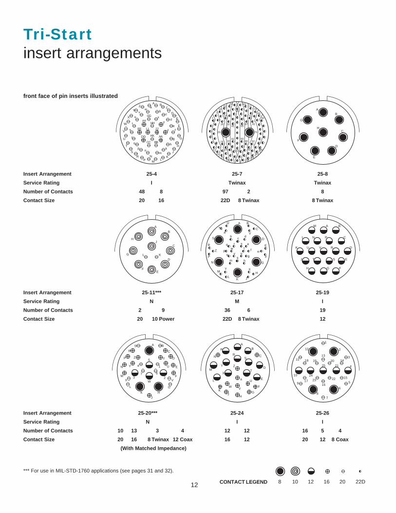
Tri-Startinsert arrangements
Insert Arrangement 25-4 25-7 25-8
Service Rating I Twinax Twinax
Number of Contacts 48 8 97 2 8
Contact Size 20 16 22D 8 Twinax 8 Twinax
Insert Arrangement 25-11*** 25-17 25-19
Service Rating N M I
Number of Contacts 2 9 36 6 19
Contact Size 20 10 Power 22D 8 Twinax 12
Insert Arrangement 25-20*** 25-24 25-26
Service Rating N I I
Number of Contacts 10 13 3 4 12 12 16 5 4
Contact Size 20 16 8 Twinax 12 Coax 16 12 20 12 8 Coax
(With Matched Impedance)
CONTACT LEGEND
*** For use in MIL-STD-1760 applications (see pages 31 and 32).
A BC
D
E
F
G
H
J
KL
M
NP
RS
T
U
V
W
X
YZ a
bc
d
ef
g
hk
mn
p
q
r
t
u
vw
x
y
zs JJ
KK
LL
AA
BBCC
DD
EE
FF
GG
HH
1
6
7
15
16
18
19
21
22
24
26
28
29
32
33
41
42
46
53
59
60
64
67
68
72
74
76
78
79
81
82
84
85
93
94
99
25 75
AB
C
D
E
F
G
H
A
B
C
D
EF
G
HJ
KL
A B
C
D
E
F
G
H
JKL
M
N
P
R
S
T
U
V
W
XY
Z
ab
cd
e
f
gh
km
np
q r st
uv
w
A B
C
D
E
FGH
J
K
L
M
N P
R
ST
U V
A B
C
D
E
F
G
H
J
K
L
M
N
P
R
S
T
U
VWX
Y
Z
1
23
4
5
67
AB
C
D
E
F
GH
JK
L
M
N
P
RS
T
U
VW
X
Y Z
a
1
2
3
4
5
6
78
9
10
11
12
13
14
15
1617
18 19 20
21
222324
25
8 10 12 16 20 22D
13
front face of pin inserts illustrated
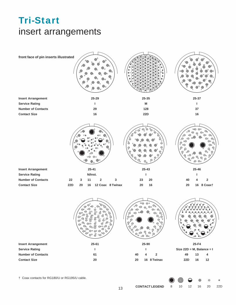
Insert Arrangement 25-29 25-35 25-37
Service Rating I M I
Number of Contacts 29 128 37
Contact Size 16 22D 16
Insert Arrangement 25-41 25-43 25-46
Service Rating N/Inst. I I
Number of Contacts 22 3 11 2 3 23 20 40 4 2
Contact Size 22D 20 16 12 Coax 8 Twinax 20 16 20 16 8 Coax†
CONTACT LEGEND
Tri-Startinsert arrangements
Insert Arrangement 25-61 25-90 25-F4
Service Rating I I Size 22D = M, Balance = I
Number of Contacts 61 40 4 2 49 13 4
Contact Size 20 20 16 8 Twinax 22D 16 12
† Coax contacts for RG180/U or RG195/U cable.
AB
C
D
E
F
GHJ
K
L
M
N
P
RS T
U
V
W
XY
Z
a
b c
d
e
f
1
4
7
8
14
15
24
25
35
36
47
48
58
59
70
71
81
82
93
94
104
105
114
115
121
125
128
A B
C
D
E
F
G
HJ
K
LM
N
P
R
S
T
U
VW
X
Y
Z
ab
c
d
e
fg
hk
m
np
qr
BP
CN
DM
EL
F
GH
J
K
A
RY
X S
W
Z
T
UV
de
np
q g
ac
bj
k h
ms t
r
i
A BC
D
E
F
G
H
JK
LMNP
R
S
T
U
V
W
XY
Z
a
b
c
d
ef
g
h
k
m
np
q
r
stu
v
w
x
AB
C
D
E
F
G
H
JKL
M
N
P
R
S
T
U
V
W
XY
Za
b
cd
e
fgh
k
mn
p
qr
s
tu
v
w
xy
z
AA
AB
C
D
E
F
G
H
J
KLMN
PR
S
T
U
V
W
X
YZa b
cd
e
f
g
hi
jkmn
p
q
r
s
tu
v
w
x
y
z
BBCC
DD
EE
FF
GG HH
JJ
KK
LL
MM
NN
AA
PP
A
B
C
D
E
F
G
H
JKLM
N
a
P
R
S
T
U
V
W
X
Y
Z
b
c
d
efgh
AA
k
q
m
n
p
r
st
u
v
w
xy
z
1
17
18
19
49
35
20
21
22
23
1615
48
59
60 66 64
65
37 50 51 41 42 4331
3038 39 40 29
2726
25
24
54636261
36
325352
4455
56
57
46
3414
13
45
12
11
10
9
8
7
6
5
43
2
33
28
47
58
8 10 12 16 20 22D
14
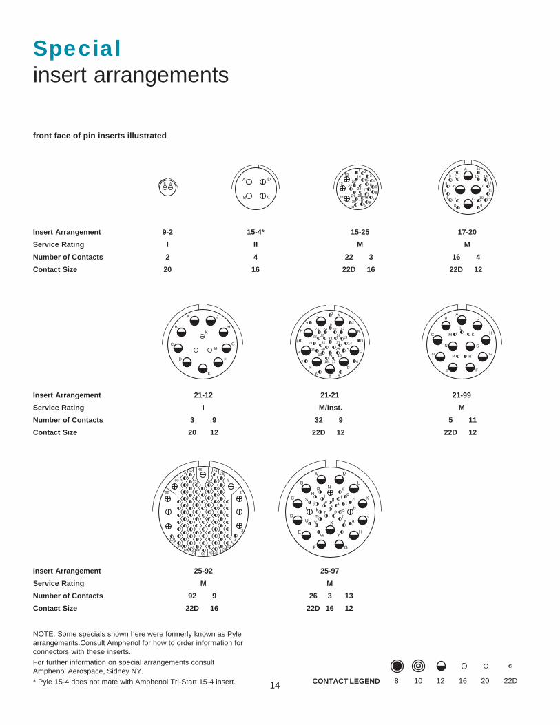
Specialinsert arrangements
front face of pin inserts illustrated
Insert Arrangement 9-2 15-4* 15-25 17-20
Service Rating I II M M
Number of Contacts 2 4 22 3 16 4
Contact Size 20 16 22D 16 22D 12
Insert Arrangement 21-12 21-21 21-99
Service Rating I M/Inst. M
Number of Contacts 3 9 32 9 5 11
Contact Size 20 12 22D 12 22D 12
CONTACT LEGEND
NOTE: Some specials shown here were formerly known as Pylearrangements.Consult Amphenol for how to order information forconnectors with these inserts.
For further information on special arrangements consultAmphenol Aerospace, Sidney NY.
* Pyle 15-4 does not mate with Amphenol Tri-Start 15-4 insert.
Insert Arrangement 25-92 25-97
Service Rating M M
Number of Contacts 92 9 26 3 13
Contact Size 22D 16 22D 16 12
ABA
B C
D3
2113
12
11
4
5
6
78
910
1415
1617
181920
2322
21
24
25
A
B
C
D
123
4
5
6 7
8 9
10 11
12
13
1415
16
A
B
C
D
E
K
F
MG
H
J
L
1
2
3
4
56
7
8
9 10
A
B
C
D
E
F
G
H
J
11 12
13
14
15
16
1718
1920
21
22
23 24
25 26
27
28
29
30
3132
AB
C
D
E F
G
H
J
K
L
M
N
P R
S
1
3
4
5
1324
36
4667
57
79
90
98
101
9789
7866
56 45 3523
12
A M
B LN
C K
D J
E H
F G
W Y
XU aV Zm r
n p skT
SR
P ed
c
btu
fghw
vj
8 10 12 16 20 22D
15
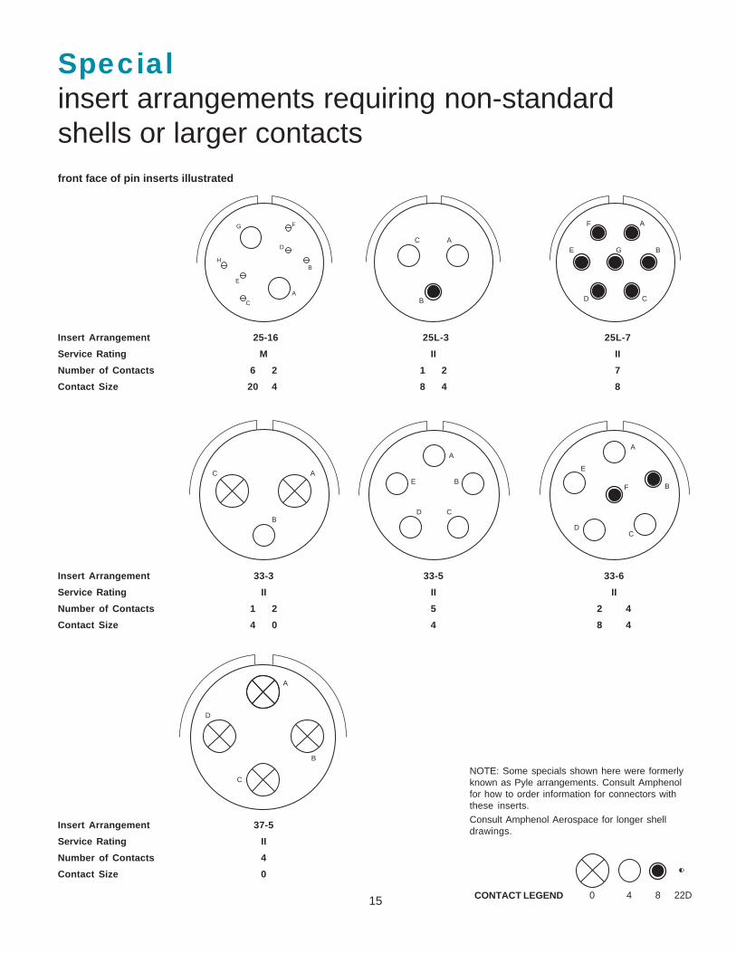
Specialinsert arrangements requiring non-standardshells or larger contactsfront face of pin inserts illustrated
Insert Arrangement 25-16 25L-3 25L-7
Service Rating M II II
Number of Contacts 6 2 1 2 7
Contact Size 20 4 8 4 8
Insert Arrangement 33-3 33-5 33-6
Service Rating II II II
Number of Contacts 1 2 5 2 4
Contact Size 4 0 4 8 4
CONTACT LEGEND
NOTE: Some specials shown here were formerlyknown as Pyle arrangements. Consult Amphenolfor how to order information for connectors withthese inserts.
Consult Amphenol Aerospace for longer shelldrawings.
A
B
C
D
E
FG
H
A
B
C
A
B
CD
E
F
G
B
C A
A
B
CD
E
A
B
CD
E
F
A
B
C
D
8�4�0� 22D�
Insert Arrangement 37-5
Service Rating II
Number of Contacts 4
Contact Size 0
16
M
M
.005
.13
T�4 PLACES
TT�4 PLACES
S�2 PLACES
2 PLACES
2 PLACES
R1
R2
V THREADAAB�THREAD
LL (TV)�LL (CTV)1
M (TV)�M (CTV)1
L (TV)�L (CTV)1
1.240 MAX�31.50 MAX
RED�BAND†�
BLUE�BAND††� –A–�
Z (TV)Z (CTV)1
.861 MAX�21.87 MAX�(TV)
.909 MAX�23.09 MAX�(CTV)
1.037 MAX�26.34 MAX�(TV)
1.084 MAX�27.53 MAX�(CTV)
D
�
VIEW DFOR SIZE 8 TWINAX ONLY,�RELATIVE TO
VIEW DFOR SIZE 8 COAXIAL ONLY,�RELATIVE TO
–A–�
–A–�
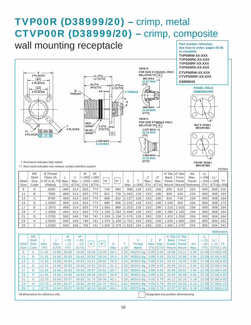
TVP00R (D38999/20) – crimp, metalCTVP00R (D38999/20) – crimp, compositewall mounting receptacle
† Red band indicates fully mated
†† Blue band indicates rear release contact retention system
MS B Thread M M1 A1 Dia. A2 Dia. AA LLShell Class 2A L L1 +.000 +.000 Z Z1 Back Front Max. +.006 LL1
Shell Size 0.1P-0.3L-TS Max. Max. –.005 –.005 R1 R2 S T Max. Max Panel Panel Panel –.000 ±.005 TTSize Code (Plated) (TV) (CTV) (TV) (CTV) Max. ±.008 (TV) (CTV) Mount Mount Thickness (TV) (CTV) ±.008
9 A .6250 .469 .514 .820 .773 .719 .594 .948 .128 .153 .198 .650 .510 .234 .905 .908 .216
11 B .7500 .469 .514 .820 .773 .812 .719 1.043 .128 .153 .198 .800 .620 .234 .905 .908 .194
13 C .8750 .469 .514 .820 .773 .906 .812 1.137 .128 .153 .198 .910 .740 .234 .905 .908 .194
15 D 1.0000 .469 .514 .820 .773 .969 .906 1.232 .128 .153 .198 1.040 .900 .234 .905 .908 .173
17 E 1.1875 .469 .514 .820 .773 1.062 .969 1.323 .128 .153 .198 1.210 1.010 .234 .905 .908 .194
19 F 1.2500 .469 .514 .820 .773 1.156 1.062 1.449 .128 .153 .198 1.280 1.130 .234 .905 .908 .194
21 G 1.3750 .500 .545 .790 .741 1.250 1.156 1.575 .128 .183 .228 1.410 1.250 .204 .905 .904 .194
23 H 1.5000 .500 .545 .790 .741 1.375 1.250 1.701 .154 .183 .228 1.530 1.360 .204 .905 .904 .242
25 J 1.6250 .500 .545 .790 .741 1.500 1.375 1.823 .154 .183 .228 1.660 1.470 .204 .905 .904 .242
MS M M1 A1 Dia. A2 Dia. LLShell L L1 +.00 +.00 V Z Z1 Back Front +.15 LL1
Shell Size Max. Max. –.13 –.13 R1 R2 S T Thread Max. Max. Panel Panel AA –.00 ±.13 TTSize Code (TV) (CTV) (TV) (CTV) Max ±.20 Metric (TV) (CTV) Mount Mount Max. (TV) (CTV) ±.20
9 A 11.91 13.06 20.83 19.63 18.26 15.09 24.1 3.25 M12X1-6g 3.89 5.03 16.66 13.11 5.94 22.99 23.06 5.49
11 B 11.91 13.06 20.83 19.63 20.62 18.26 26.5 3.25 M15X1-6g 3.89 5.03 20.22 15.88 5.94 22.99 23.06 4.93
13 C 11.91 13.06 20.83 19.63 23.01 20.62 28.9 3.25 M18X1-6g 3.89 5.03 23.42 19.05 5.94 22.99 23.06 4.93
15 D 11.91 13.06 20.83 19.63 24.61 23.01 31.3 3.25 M22X1-6g 3.89 5.03 26.59 23.01 5.94 22.99 23.06 4.39
17 E 11.91 13.06 20.83 19.63 26.97 24.61 33.7 3.25 M25X1-6g 3.89 5.03 30.96 25.81 5.94 22.99 23.06 4.93
19 F 11.91 13.06 20.83 19.63 29.36 26.97 36.9 3.25 M28X1-6g 3.89 5.03 32.94 28.98 5.94 22.99 23.06 4.93
21 G 12.70 13.84 20.07 18.82 31.75 29.36 40.1 3.25 M31X1-6g 4.65 5.79 36.12 32.16 5.18 22.99 22.96 4.93
23 H 12.70 13.84 20.07 18.82 34.93 31.75 43.3 3.91 M34X1-6g 4.65 5.79 39.29 34.93 5.18 22.99 22.96 6.15
25 J 12.70 13.84 20.07 18.82 38.10 34.93 46.4 3.91 M37X1-6g 4.65 5.79 42.47 37.69 5.18 22.99 22.96 6.15
Millimeters
Inches
All dimensions for reference only Designates true position dimensioning
Part number reference.See how to order, pages 43-46to complete.TVP00RW-XX-XXXTVPS00RK-XX-XXXTVPS00RF-XX-XXXTVPS00RS-XX-XXX
CTVP00RW-XX-XXXCTVPS00RF-XX-XXX
D38999/20
BACK PANELMOUNTING
FRONT PANELMOUNTING
A1
A2
PANEL HOLEDIMENSIONS
17
MS M M1 A1 A2 LLShell L L1 +.00 +.00 Z Z1 Back Front +.15 LL1
Shell Size Max. Max. –.13 –.13 R1 R2 S T Max. Max. Panel Panel AA –.00 ±.13 TTSize Code (TV) (CTV) (TV) (CTV) Max ±.20 (TV) (CTV) Mount Mount Max. (TV) (CTV) ±.20
9 A 5.21 6.35 20.83 19.63 18.26 15.09 24.1 3.25 3.89 5.03 16.66 13.11 5.94 22.99 23.06 5.49
11 B 5.21 6.35 20.83 19.63 20.62 18.26 26.5 3.25 3.89 5.03 20.22 15.88 5.94 22.99 23.06 4.93
13 C 5.21 6.35 20.83 19.63 23.01 20.62 28.9 3.25 3.89 5.03 23.42 19.05 5.94 22.99 23.06 4.93
15 D 5.21 6.35 20.83 19.63 24.61 23.01 31.3 3.25 3.89 5.03 26.59 23.01 5.94 22.99 23.06 4.39
17 E 5.21 6.35 20.83 19.63 26.97 24.61 33.7 3.25 3.89 5.03 30.96 25.81 5.94 22.99 23.06 4.93
19 F 5.21 6.35 20.83 19.63 29.36 26.97 36.9 3.25 3.89 5.03 32.94 28.98 5.94 22.99 23.06 4.93
21 G 5.97 7.11 20.07 18.82 31.75 29.36 40.1 3.25 4.65 5.79 36.12 32.16 5.18 22.99 22.96 4.93
23 H 5.97 7.11 20.07 18.82 34.92 31.75 43.3 3.91 4.65 5.79 39.29 34.93 5.18 22.99 22.96 6.15
25 J 5.97 7.11 20.07 18.82 38.10 34.92 46.4 3.91 4.65 5.79 42.47 37.69 5.18 22.99 22.96 6.15
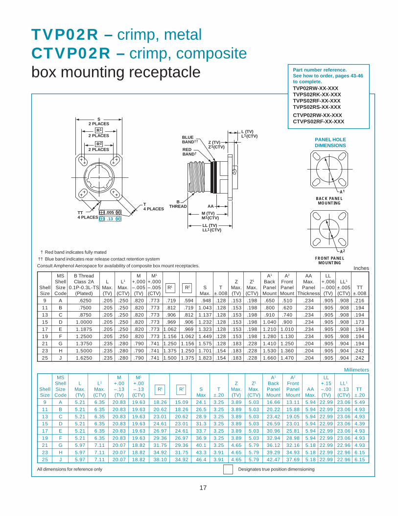
TVP02R – crimp, metalCTVP02R – crimp, compositebox mounting receptacle
† Red band indicates fully mated
†† Blue band indicates rear release contact retention system
Consult Amphenol Aerospace for availability of composite box mount receptacles.
MS B Thread M M1 A1 A2 AA LLShell Class 2A L L1 +.000 +.000 Z Z1 Back Front Max. +.006 LL1
Shell Size 0.1P-0.3L-TS Max. Max. –.005 –.005 R1 R2 S T Max. Max. Panel Panel Panel –.000 ±.005 TTSize Code (Plated) (TV) (CTV) (TV) (CTV) Max. ±.008 (TV) (CTV) Mount Mount Thickness (TV) (CTV) ±.008
9 A .6250 .205 .250 .820 .773 .719 .594 .948 .128 .153 .198 .650 .510 .234 .905 .908 .216
11 B .7500 .205 .250 .820 .773 .812 .719 1.043 .128 .153 .198 .800 .620 .234 .905 .908 .194
13 C .8750 .205 .250 .820 .773 .906 .812 1.137 .128 .153 .198 .910 .740 .234 .905 .908 .194
15 D 1.0000 .205 .250 .820 .773 .969 .906 1.232 .128 .153 .198 1.040 .900 .234 .905 .908 .173
17 E 1.1875 .205 .250 .820 .773 1.062 .969 1.323 .128 .153 .198 1.210 1.010 .234 .905 .908 .194
19 F 1.2500 .205 .250 .820 .773 1.156 1.062 1.449 .128 .153 .198 1.280 1.130 .234 .905 .908 .194
21 G 1.3750 .235 .280 .790 .741 1.250 1.156 1.575 .128 .183 .228 1.410 1.250 .204 .905 .904 .194
23 H 1.5000 .235 .280 .790 .741 1.375 1.250 1.701 .154 .183 .228 1.530 1.360 .204 .905 .904 .242
25 J 1.6250 .235 .280 .790 .741 1.500 1.375 1.823 .154 .183 .228 1.660 1.470 .204 .905 .904 .242
Millimeters
Inches
M (TV)�M (CTV)
LL (TV)�LL (CTV)
1
1
AAB�
THREAD
BLUE�BAND††�
RED�BAND†�
L (TV)�L (CTV)1
Z (TV)�Z (CTV)1
M
M
.005
.13
T�4 PLACES
TT�4 PLACES
S�2 PLACES
2 PLACES
2 PLACES
R1
R2
All dimensions for reference only Designates true position dimensioning
BACK PANELMOUNTING
FRONT PANELMOUNTING
A1
A2
PANEL HOLEDIMENSIONS
Part number reference.See how to order, pages 43-46to complete.TVP02RW-XX-XXXTVPS02RK-XX-XXXTVPS02RF-XX-XXXTVPS02RS-XX-XXX
CTVP02RW-XX-XXXCTVPS02RF-XX-XXX
18
1.234 MAX�31.34 MAX��1.220 MAX�31.00 MAX B THREAD
D
V THREAD
.359 MAX�9.12 MAX
.359 MAX�9.12 MAX
.591 +.003�–.000�
15.01 +.08�–.00
BLUE BAND†�
1.234 MAX�31.34 MAX
Q
1.656 MAX�42.06 MAX
1.797 MAX�45.64 MAX
VIEW DFOR SIZE 8 TWINAX ONLY,�RELATIVE TO
VIEW DFOR SIZE 8 COAXIAL ONLY,�RELATIVE TO
–A–�
–A–�
–A–�
V THREAD
.591 +.003�–.000�
15.01 +.08�–.00
–A–�
QB THREAD
D
BLUE BAND†�
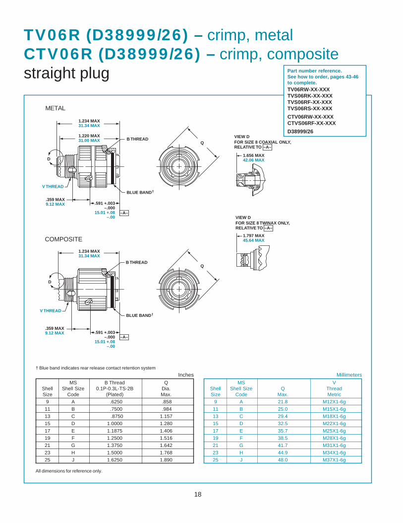
TV06R (D38999/26) – crimp, metalCTV06R (D38999/26) – crimp, compositestraight plug
MS B Thread QShell Shell Size 0.1P-0.3L-TS-2B Dia.Size Code (Plated) Max.
9 A .6250 .858
11 B .7500 .984
13 C .8750 1.157
15 D 1.0000 1.280
17 E 1.1875 1.406
19 F 1.2500 1.516
21 G 1.3750 1.642
23 H 1.5000 1.768
25 J 1.6250 1.890
† Blue band indicates rear release contact retention system
All dimensions for reference only.
Part number reference.See how to order, pages 43-46to complete.TV06RW-XX-XXXTVS06RK-XX-XXXTVS06RF-XX-XXXTVS06RS-XX-XXX
CTV06RW-XX-XXXCTVS06RF-XX-XXX
D38999/26
MS VShell Shell Size Q ThreadSize Code Max. Metric
9 A 21.8 M12X1-6g
11 B 25.0 M15X1-6g
13 C 29.4 M18X1-6g
15 D 32.5 M22X1-6g
17 E 35.7 M25X1-6g
19 F 38.5 M28X1-6g
21 G 41.7 M31X1-6g
23 H 44.9 M34X1-6g
25 J 48.0 M37X1-6g
Inches Millimeters
METAL
COMPOSITE
19
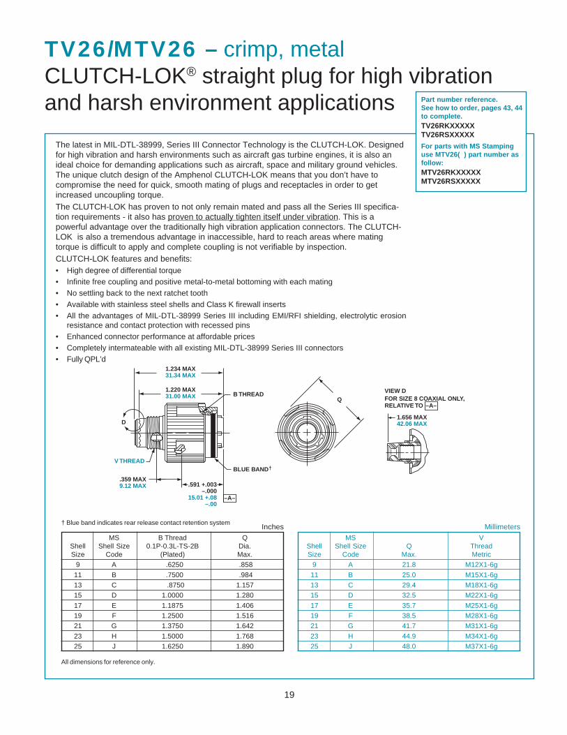
TV26/MTV26 – crimp, metalCLUTCH-LOK® straight plug for high vibrationand harsh environment applications
The latest in MIL-DTL-38999, Series III Connector Technology is the CLUTCH-LOK. Designedfor high vibration and harsh environments such as aircraft gas turbine engines, it is also anideal choice for demanding applications such as aircraft, space and military ground vehicles.The unique clutch design of the Amphenol CLUTCH-LOK means that you don’t have tocompromise the need for quick, smooth mating of plugs and receptacles in order to getincreased uncoupling torque.The CLUTCH-LOK has proven to not only remain mated and pass all the Series III specifica-tion requirements - it also has proven to actually tighten itself under vibration. This is apowerful advantage over the traditionally high vibration application connectors. The CLUTCH-LOK is also a tremendous advantage in inaccessible, hard to reach areas where matingtorque is difficult to apply and complete coupling is not verifiable by inspection.CLUTCH-LOK features and benefits:• High degree of differential torque• Infinite free coupling and positive metal-to-metal bottoming with each mating• No settling back to the next ratchet tooth• Available with stainless steel shells and Class K firewall inserts• All the advantages of MIL-DTL-38999 Series III including EMI/RFI shielding, electrolytic erosion
resistance and contact protection with recessed pins• Enhanced connector performance at affordable prices• Completely intermateable with all existing MIL-DTL-38999 Series III connectors• Fully QPL’d
Part number reference.See how to order, pages 43, 44to complete.TV26RKXXXXXTV26RSXXXXX
For parts with MS Stampinguse MTV26( ) part number asfollow:MTV26RKXXXXXMTV26RSXXXXX
MS B Thread QShell Shell Size 0.1P-0.3L-TS-2B Dia.Size Code (Plated) Max.
9 A .6250 .858
11 B .7500 .984
13 C .8750 1.157
15 D 1.0000 1.280
17 E 1.1875 1.406
19 F 1.2500 1.516
21 G 1.3750 1.642
23 H 1.5000 1.768
25 J 1.6250 1.890
† Blue band indicates rear release contact retention system
All dimensions for reference only.
MS VShell Shell Size Q ThreadSize Code Max. Metric
9 A 21.8 M12X1-6g
11 B 25.0 M15X1-6g
13 C 29.4 M18X1-6g
15 D 32.5 M22X1-6g
17 E 35.7 M25X1-6g
19 F 38.5 M28X1-6g
21 G 41.7 M31X1-6g
23 H 44.9 M34X1-6g
25 J 48.0 M37X1-6g
Inches Millimeters
1.234 MAX�31.34 MAX��1.220 MAX�31.00 MAX B THREAD
D
V THREAD
.359 MAX�9.12 MAX .591 +.003�
–.000�15.01 +.08�
–.00
BLUE BAND†�
Q
1.656 MAX�42.06 MAX
VIEW DFOR SIZE 8 COAXIAL ONLY,�RELATIVE TO –A–�
–A–�
20
T•�
C
H
S�2 PLACES
PANEL THICKNESS�.062 MIN .125 MAX�1.57 MIN 3.18 MAX
BLUE BAND††�
.378 MAX�9.60 MAX
1.280 MAX�32.51 MAX
K REF�SHELL SIZES 9/11 –�
.871 22.12�SHELL SIZES 13/25 –�
.878 22.30
.091 MAX�2.31 MAX
B THREAD
A•�
V THREAD
D
RED�BAND†�
–A–�
.794 MAX�20.17 MAX
.940 MAX�23.88 MAX
VIEW DFOR SIZE 8 TWINAX ONLY,�RELATIVE TO
VIEW DFOR SIZE 8 COAXIAL ONLY,�RELATIVE TO
–A–�
–A–�
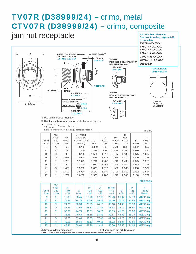
TV07R (D38999/24) – crimp, metalCTV07R (D38999/24) – crimp, compositejam nut receptacle
† Red band indicates fully mated
†† Blue band indicates rear release contact retention system
★ .059 dia min.1.5 dia min.Formed lockwire hole design (6 holes) is optional
MS B Thread HShell A• Class 2A D1 D2 Hex T•
Shell Size +.000 0.1P-0.3L-TS C +.010 +.000 +.017 S +.010Size Code –.010 (Plated) Max. –.000 –.010 –.016 ±.010 –.000
9 A .669 .6250 1.199 .700 .670 .875 1.062 .697
11 B .769 .7500 1.386 .825 .770 1.000 1.250 .822
13 C .955 .8750 1.511 1.010 .955 1.188 1.375 1.007
15 D 1.084 1.0000 1.636 1.135 1.085 1.312 1.500 1.134
17 E 1.208 1.1875 1.761 1.260 1.210 1.438 1.625 1.259
19 F 1.333 1.2500 1.949 1.385 1.335 1.562 1.812 1.384
21 G 1.459 1.3750 2.073 1.510 1.460 1.688 1.938 1.507
23 H 1.575 1.5000 2.199 1.635 1.585 1.812 2.062 1.634
25 J 1.709 1.6250 2.323 1.760 1.710 2.000 2.188 1.759
MSShell A• D1 D2 H Hex T• V
Shell Size +.00 C +.25 +.00 +.43 S +.25 ThreadSize Code –.25 Max. –.00 –.25 –.41 ±.25 –.00 Metric
9 A 16.99 30.45 17.78 17.02 22.23 26.97 17.70 M12X1-6g
11 B 19.53 35.20 20.96 19.59 25.40 31.75 20.88 M15X1-6g
13 C 24.26 38.38 25.65 24.26 30.18 34.93 25.58 M18X1-6g
15 D 27.53 41.55 28.83 27.56 33.32 38.10 28.80 M22X1-6g
17 E 30.68 44.73 32.01 30.73 36.53 41.28 31.98 M25X1-6g
19 F 33.86 49.50 35.18 33.91 39.67 46.02 35.15 M28X1-6g
21 G 37.06 52.65 38.35 37.08 42.80 49.23 38.28 M31X1-6g
23 H 40.01 55.85 41.53 40.26 46.02 52.37 41.50 M34X1-6g
25 J 43.41 59.00 44.70 43.43 50.80 55.58 44.68 M37X1-6g
Millimeters
All dimensions for reference only • D shaped panel cut-out dimensionsNOTE: Deep reach receptacles are available for panel thicknesses up to .750 max.
3 lockwire holes
PANEL HOLEDIMENSIONS
JAM NUTD-HOLE
MOUNTING
D1
D2
Part number reference.See how to order, pages 43-46to complete.TV07RW-XX-XXXTVS07RK-XX-XXXTVS07RF-XX-XXXTVS07RS-XX-XXX
CTV07RW-XX-XXXCTVS07RF-XX-XXX
D38999/24
Inches
21
GG (TV)�GG (CTV)1
S (TV)�S (CTV)�
2 PLACES1
B�THREAD
LL (TV)�LL (CTV)1
1M (TV)�M (CTV)
.280 MIN FULL THD�7.11 MIN FULL THD
L (TV)�L (CTV)1
Z (TV)�Z (CTV)1
1.240MAX�31.50 MAX
V THREAD
D
–A–��
RED�BAND�†�
BLUE�BAND�††�
.861 MAX�21.87 MAX�(TV)
.909 MAX�23.09 MAX�(CTV)
1.037 MAX�26.34 MAX�(TV)
1.084 MAX�27.53 MAX�(CTV)
VIEW DFOR SIZE 8 TWINAX ONLY,�RELATIVE TO
VIEW DFOR SIZE 8 COAXIAL ONLY,�RELATIVE TO
–A–�
–A–�
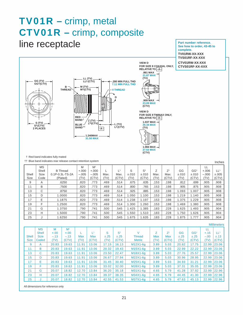
TV01R – crimp, metalCTV01R – crimp, compositeline receptacle
† Red band indicates fully mated
†† Blue band indicates rear release contact retention system
MS M M1 LLShell +.00 +.00 L L1 S S1 V Z Z1 GG GG1 +.15 LL1
Shell Size –.13 –.13 Max Max ±.25 ±.25 Thread Max Max ±.25 ±.25 –.00 ±.13Size Coded (TV) (CTV) (TV) (CTV) (TV) (CTV) Metric (TV) (CTV) (TV) (CTV) (TV) (CTV)
9 A 20.83 19.63 11.91 13.06 17.15 16.13 M12X1-6g 3.89 5.03 20.62 17.75 22.99 23.06
11 B 20.83 19.63 11.91 13.06 20.32 19.43 M15X1-6g 3.89 5.03 22.99 22.22 22.99 23.06
13 C 20.83 19.63 11.91 13.06 23.50 22.47 M18X1-6g 3.89 5.03 27.76 25.57 22.99 23.06
15 D 20.83 19.63 11.91 13.06 26.67 27.94 M22X1-6g 3.89 5.03 30.96 28.95 22.99 23.06
17 E 20.83 19.63 11.91 13.06 31.45 30.40 M25X1-6g 3.89 5.03 34.93 31.21 22.99 23.06
19 F 20.83 19.63 11.91 13.06 33.02 32.00 M28X1-6g 3.89 5.03 37.31 35.05 22.99 23.06
21 G 20.07 18.82 12.70 13.84 36.20 35.18 M31X1-6g 4.65 5.79 41.28 37.92 22.99 22.96
23 H 20.07 18.82 12.70 13.84 39.37 38.35 M34X1-6g 4.65 5.79 44.45 41.30 22.99 22.96
25 J 20.07 18.82 12.70 13.84 42.55 41.53 M37X1-6g 4.65 5.79 47.63 45.13 22.99 22.96
Millimeters
All dimensions for reference only
MS M M1 LLShell B Thread +.000 +.000 L L1 S S1 Z Z1 GG GG1 +.006 LL1
Shell Size 0.1P-0.3L-TS-2A –.005 –.005 Max. Max. ±.010 ±.010 Max. Max. ±.010 ±.010 –.000 ±.005Size Code (Plated) (TV) (CTV) (TV) (CTV) (TV) (CTV) (TV) (CTV) (TV) (CTV) (TV) (CTV)
9 A .6250 .820 .773 .469 .514 .675 .635 .153 .198 .812 .699 .905 .908
11 B .7500 .820 .773 .469 .514 .800 .765 .153 .198 .905 .875 .905 .908
13 C .8750 .820 .773 .469 .514 .925 .885 .153 .198 1.093 1.007 .905 .908
15 D 1.0000 .820 .773 .469 .514 1.050 1.100 .153 .198 1.219 1.140 .905 .908
17 E 1.1875 .820 .773 .469 .514 1.238 1.197 .153 .198 1.375 1.229 .905 .908
19 F 1.2500 .820 .773 .469 .514 1.300 1.260 .153 .198 1.469 1.380 .905 .908
21 G 1.3750 .790 .741 .500 .545 1.425 1.385 .183 .228 1.625 1.493 .905 .904
23 H 1.5000 .790 .741 .500 .545 1.550 1.510 .183 .228 1.750 1.626 .905 .904
25 J 1.6250 .790 .741 .500 .545 1.675 1.635 .183 .228 1.875 1.777 .905 .904
Inches
Part number reference.See how to order, 43-45 tocomplete.TV01RW-XX-XXXTVS01RF-XX-XXX
CTV01RW-XX-XXXCTVS01RF-XX-XXX
22
BLUE�BAND†�
G.190 +.010�
–.000�4.82 +.26�
–.00��
B�THREAD
Q
.591 +.003�–.000�
15.01+.08�–.00
3.59 MAX�9.12 MAX
GG
M.005
M.13
.138-32UNC-2B�HELICAL COIL
�
–A–�
R
R
1.656 MAX�42.06 MAX
1.797 MAX�45.64 MAX
VIEW DFOR SIZE 8 TWINAX ONLY,�RELATIVE TO
VIEW DFOR SIZE 8 COAXIAL ONLY,�RELATIVE TO
–A–�
–A–�
D
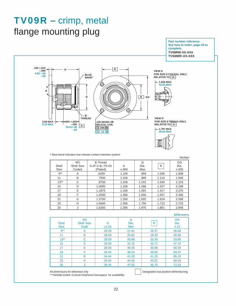
TV09R – crimp, metalflange mounting plug
† Blue band indicates rear release contact retention system
MS Q GGShell Shell Size G Dia. R Dia.Size Code ±1.52 Max ±.13
9** A 28.09 21.82 26.37 46.69
11 B 28.09 24.62 28.32 49.48
13** C 28.09 28.98 31.50 53.95
15 D 28.09 32.16 33.71 57.10
17 E 28.09 35.33 35.99 60.33
19 F 34.44 38.10 39.55 63.37
21 G 34.44 41.28 41.25 65.23
23 H 34.44 44.45 43.51 69.16
25 J 34.44 47.63 45.75 72.34
Millimeters
All dimensions for reference only Designates true position dimensioning** Partially tooled. Consult Amphenol Aerospace for availability
MS B Thread Q GGShell Shell Size 0.1P-0.3L-TS-2A G Dia. R Dia.Size Coded (Plated) ±.060 Max ±.005
9** A .6250 1.106 .859 1.038 1.838
11 B .7500 1.106 .969 1.115 1.948
13** C .8750 1.106 1.141 1.240 2.124
15 D 1.0000 1.106 1.266 1.327 2.248
17 E 1.1875 1.106 1.391 1.417 2.375
19 F 1.2500 1.356 1.500 1.557 2.495
21 G 1.3750 1.356 1.625 1.624 2.568
23 H 1.5000 1.356 1.750 1.713 2.723
25 J 1.6250 1.356 1.875 1.801 2.848
Inches
Part number reference.See how to order, page 43 tocomplete.TV09RW-XX-XXXTVS09RF-XX-XXX
23
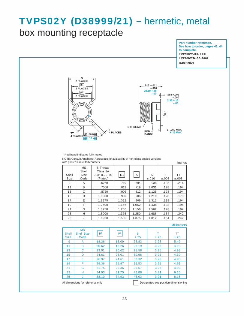
TVPS02Y (D38999/21) – hermetic, metalbox mounting receptacle
† Red band indicates fully mated
NOTE: Consult Amphenol Aerospace for availability of non-glass-sealed versionswith printed circuit tail contacts.
Millimeters
All dimensions for reference only Designates true position dimensioning
Inches
MSShell Shell Size R1 R2 S T TTSize Code ±.25 ±.20 ±.20
9 A 18.26 15.09 23.83 3.25 5.49
11 B 20.62 18.26 26.19 3.25 4.93
13 C 23.01 20.62 28.58 3.25 4.93
15 D 24.61 23.01 30.96 3.25 4.39
17 E 26.97 24.61 33.32 3.25 4.93
19 F 29.36 26.97 36.53 3.25 4.93
21 G 31.75 29.36 39.67 3.25 4.93
23 H 34.93 31.75 42.88 3.91 6.15
25 J 38.10 34.93 46.02 3.91 6.15
MS B ThreadShell Class 2A
Shell Size 0.1P-0.3L-TS R1 R2 S T TTSize Code (Plated) ±.010 ±.008 ±.008
9 A .6250 .719 .594 .938 .128 .216
11 B .7500 .812 .719 1.031 .128 .194
13 C .8750 .906 .812 1.125 .128 .194
15 D 1.0000 .969 .906 1.219 .128 .173
17 E 1.1875 1.062 .969 1.312 .128 .194
19 F 1.2500 1.156 1.062 1.438 .128 .194
21 G 1.3750 1.250 1.156 1.562 .128 .194
23 H 1.5000 1.375 1.250 1.688 .154 .242
25 J 1.6250 1.500 1.375 1.812 .154 .242
Part number reference.See how to order, pages 43, 44to complete.TVPS02Y-XX-XXXTVPS02YN-XX-XXX
D38999/21
S�2 PLACES
R
R2
1
2 PLACES
2 PLACES
TT�4 PLACES
.005
.13
M
M
T�4 PLACES
B THREAD
RED�BAND†�
.250 MAX�6.35 MAX
1
.913 +.011�–.000
23.19 +.28�–.00 .093 +.006�
–.0002.36 +.15�
–.00
24
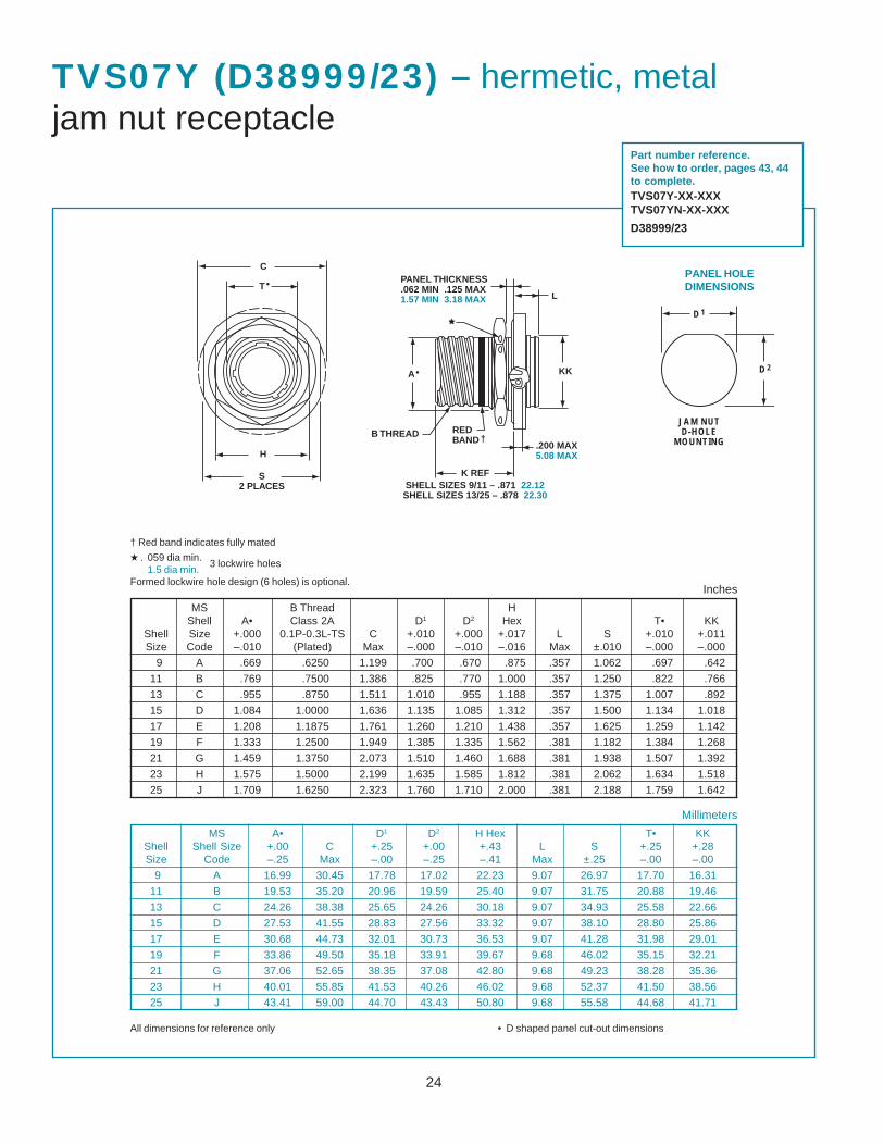
TVS07Y (D38999/23) – hermetic, metaljam nut receptacle
† Red band indicates fully mated
★ . 059 dia min.1.5 dia min.
Formed lockwire hole design (6 holes) is optional.
3 lockwire holes
MS B Thread HShell A• Class 2A D1 D2 Hex T• KK
Shell Size +.000 0.1P-0.3L-TS C +.010 +.000 +.017 L S +.010 +.011Size Code –.010 (Plated) Max –.000 –.010 –.016 Max ±.010 –.000 –.000
9 A .669 .6250 1.199 .700 .670 .875 .357 1.062 .697 .642
11 B .769 .7500 1.386 .825 .770 1.000 .357 1.250 .822 .766
13 C .955 .8750 1.511 1.010 .955 1.188 .357 1.375 1.007 .892
15 D 1.084 1.0000 1.636 1.135 1.085 1.312 .357 1.500 1.134 1.018
17 E 1.208 1.1875 1.761 1.260 1.210 1.438 .357 1.625 1.259 1.142
19 F 1.333 1.2500 1.949 1.385 1.335 1.562 .381 1.182 1.384 1.268
21 G 1.459 1.3750 2.073 1.510 1.460 1.688 .381 1.938 1.507 1.392
23 H 1.575 1.5000 2.199 1.635 1.585 1.812 .381 2.062 1.634 1.518
25 J 1.709 1.6250 2.323 1.760 1.710 2.000 .381 2.188 1.759 1.642
MS A• D1 D2 H Hex T• KKShell Shell Size +.00 C +.25 +.00 +.43 L S +.25 +.28Size Code –.25 Max –.00 –.25 –.41 Max ±.25 –.00 –.00
9 A 16.99 30.45 17.78 17.02 22.23 9.07 26.97 17.70 16.31
11 B 19.53 35.20 20.96 19.59 25.40 9.07 31.75 20.88 19.46
13 C 24.26 38.38 25.65 24.26 30.18 9.07 34.93 25.58 22.66
15 D 27.53 41.55 28.83 27.56 33.32 9.07 38.10 28.80 25.86
17 E 30.68 44.73 32.01 30.73 36.53 9.07 41.28 31.98 29.01
19 F 33.86 49.50 35.18 33.91 39.67 9.68 46.02 35.15 32.21
21 G 37.06 52.65 38.35 37.08 42.80 9.68 49.23 38.28 35.36
23 H 40.01 55.85 41.53 40.26 46.02 9.68 52.37 41.50 38.56
25 J 43.41 59.00 44.70 43.43 50.80 9.68 55.58 44.68 41.71
Millimeters
Inches
All dimensions for reference only • D shaped panel cut-out dimensions
Part number reference.See how to order, pages 43, 44to complete.TVS07Y-XX-XXXTVS07YN-XX-XXX
D38999/23
C
T•�
H
S�2 PLACES
K REF
.200 MAX�5.08 MAX
KK
RED�BAND†�B THREAD
A•�
L
PANEL THICKNESS�.062 MIN .125 MAX�1.57 MIN 3.18 MAX
SHELL SIZES 9/11 – .871 22.12�SHELL SIZES 13/25 – .878 22.30
PANEL HOLEDIMENSIONS
JAM NUTD-HOLE
MOUNTING
D1
D2
25
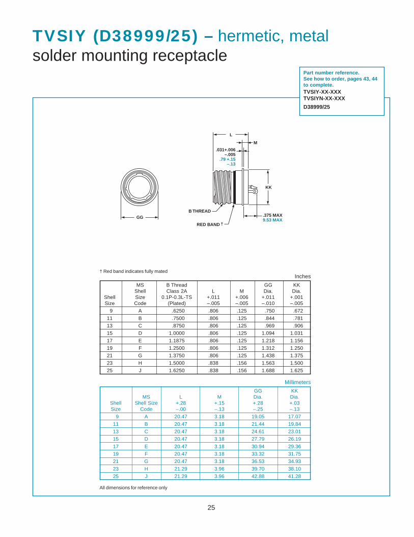
TVSIY (D38999/25) – hermetic, metalsolder mounting receptacle
MS B Thread GG KKShell Class 2A L M Dia. Dia.
Shell Size 0.1P-0.3L-TS +.011 +.006 +.011 +.001Size Code (Plated) –.005 –.005 –.010 –.005
9 A .6250 .806 .125 .750 .672
11 B .7500 .806 .125 .844 .781
13 C .8750 .806 .125 .969 .906
15 D 1.0000 .806 .125 1.094 1.031
17 E 1.1875 .806 .125 1.218 1.156
19 F 1.2500 .806 .125 1.312 1.250
21 G 1.3750 .806 .125 1.438 1.375
23 H 1.5000 .838 .156 1.563 1.500
25 J 1.6250 .838 .156 1.688 1.625
GG KKMS L M Dia. Dia.
Shell Shell Size +.28 +.15 +.28 +.03Size Code –.00 –.13 –.25 –.13
9 A 20.47 3.18 19.05 17.07
11 B 20.47 3.18 21.44 19.84
13 C 20.47 3.18 24.61 23.01
15 D 20.47 3.18 27.79 26.19
17 E 20.47 3.18 30.94 29.36
19 F 20.47 3.18 33.32 31.75
21 G 20.47 3.18 36.53 34.93
23 H 21.29 3.96 39.70 38.10
25 J 21.29 3.96 42.88 41.28
Millimeters
Inches
All dimensions for reference only
Part number reference.See how to order, pages 43, 44to complete.TVSIY-XX-XXXTVSIYN-XX-XXX
D38999/25
† Red band indicates fully mated
GGB THREAD
RED BAND †�
.375 MAX�9.53 MAX
KK
M
L
.031+.006��–.005�
.79 +.15��–.13

26
TVSHIY (D38999/27) – hermetic, metalweld mounting receptacle
GG
B THREAD
RED BAND †�
L
M
.375 MAX�9.53 MAX
MS B Thread GGShell Class 2A L M Dia.
Shell Size 0.1P-0.3L-TS +.011 +.006 +.010Size Code (Plated) –.000 –.005 –.000
9 A .6250 .806 .125 .973
11 B .7500 .806 .125 1.095
13 C .8750 .806 .125 1.221
15 D 1.0000 .806 .125 1.347
17 E 1.1875 .806 .125 1.434
19 F 1.2500 .806 .125 1.579
21 G 1.3750 .806 .125 1.721
23 H 1.5000 .838 .156 1.886
25 J 1.6250 .838 .156 1.973
GGMS L M Dia.
Shell Shell Size +.28 +.15 +.25Size Code –.00 –.13 –.00
9 A 20.47 3.18 24.71
11 B 20.47 3.18 27.81
13 C 20.47 3.18 31.01
15 D 20.47 3.18 34.21
17 E 20.47 3.18 36.42
19 F 20.47 3.18 40.11
21 G 20.47 3.18 43.71
23 H 21.29 3.96 47.90
25 J 21.29 3.96 50.11
Millimeters
Inches
All dimensions for reference only
† Red band indicates fully mated
Part number reference.See how to order, pages 43, 44to complete.TVSHIY-XX-XXXTVSHIYN-XX-XXX
D38999/27

27
TV Breakaway Fail Safe Connectorsquick-disconnect with an axial pull of lanyard
Amphenol Tri-Start Breakaway Fail Safe Con-nectors provide unequalled performance inenvironments requiring instant disengage-ment.
Designed to provide quick disconnect of aconnector plug and receptacle with an axialpull on the lanyard, the “Breakaway” Fail Safeconnector family offers a wide range ofelectrical and mechanical features:• Instant decoupling and damage free
separation• Completely intermateable with standard
receptacles (D38999/20 and /24)• Inventory support commonality through the
use of standard insert arrangements andcontacts
Breakaway un-mating is initiated by applying apull force to the lanyard which causes the oper-ating sleeve on the plug to move away from thereceptacle. Coupling segments on the plug then moveaway from the mating receptacle while expanding, thus releasing the receptacle.After completion of the un-mating sequence, spring compression returns thesleeve and segments to their original positions. Un-mating of the plug may alsobe accomplished by normal rotation of the coupling ring without affecting thebreakaway capability.
The Tri-Start Breakaway Fail Safe connector features which provide EMI/EMPshielding in excess of MIL-DTL-38999 Series III requirements:
• Solid metal-to-metal coupling• EMI grounding fingers• Conductive finishes
Amphenol Breakaway Fail Safe connectors are qualified to MIL-DTL-38999/29, /30 and /31 (for MIL-STD-1760 Stores Management applications). In fact,Amphenol offers more qualified Breakaway shell size and insert combina-tions than any other QPL supplier.
In addition to standard Breakaway connectors, Amphenol also manufacturescustom breakaway connectors including those with:• Highly durable non-metallic operating sleeves in a variety of lengths and
diameters• Increased pull-force capability• Low-profile designs• Custom lanyard lengths and backshells• Low force separation capabilities• Low insertion/separation force contacts• Non-cadmium finishesWhether you need a standard Breakaway, one of our custom Breakaways or, aunique Breakaway design, please contact your local Amphenol representative.
Contact Amphenol Aerospace for more information on breakaway, quick-disconnect connectors. Other Amphenol cylindrical families (MIL-DTL-38999Series I & II, MIL-C-26482, MIL-C-83723) also offer breakaway quick-disconnectconnectors.
Breakaway with Coax Contacts
Special configuration Fail Safe used onspace telescope application. Lanyard is
replaced by a swivel ring for remote disconnectand “wing arms” have been added for manualactuation accessibility by gloved astronauts.
Amphenol offers a variety of lanyard plug styles including MIL-STD-1760types 1, 2 and 6 for Stores Management applications.
TYPE 2 TYPE 6 TYPE 1
28
D
.374 MAX�9.50 MAX�OUTER SLEEVE MOVEMENT�DURING UNMATING THREAD RELEASE
LANYARD�PULLED TAUT�AGAINST A �.500 ±.031�12.70 ±.79�DIA MANDREL
V THREAD�METRIC
1.781 MAX�45.24 MAX
2.375 MAX�60.33 MAX
BLUE BAND †�
B
.359 MAX�9.12 MAX�
LANYARD LENGTH�(See Lanyard Length Table)
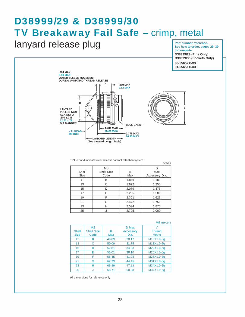
D38999/29 & D38999/30TV Breakaway Fail Safe – crimp, metallanyard release plug
† Blue band indicates rear release contact retention system
MS D Max VShell Shell Size B Accessory ThreadSize Code Max Dia. Metric
11 B 46.89 28.17 M15X1.0-6g
13 C 50.09 31.75 M18X1.0-6g
15 D 52.81 34.93 M22X1.0-6g
17 E 56.01 38.10 M25X1.0-6g
19 F 58.45 41.28 M28X1.0-6g
21 G 62.79 44.45 M31X1.0-6g
23 H 65.89 47.63 M34X1.0-6g
25 J 68.71 50.08 M37X1.0-6g
Millimeters
All dimensions for reference only
MS DShell Shell Size B MaxSize Code Max Accessory Dia.
11 B 1.846 1.109
13 C 1.972 1.250
15 D 2.079 1.375
17 E 2.205 1.500
19 F 2.301 1.625
21 G 2.472 1.750
23 H 2.594 1.875
25 J 2.705 2.000
Inches
Part number reference.See how to order, pages 29, 30to complete.D38999/29 (Pins Only)D38999/30 (Sockets Only)
88-5565XX-XX91-5565XX-XX
29
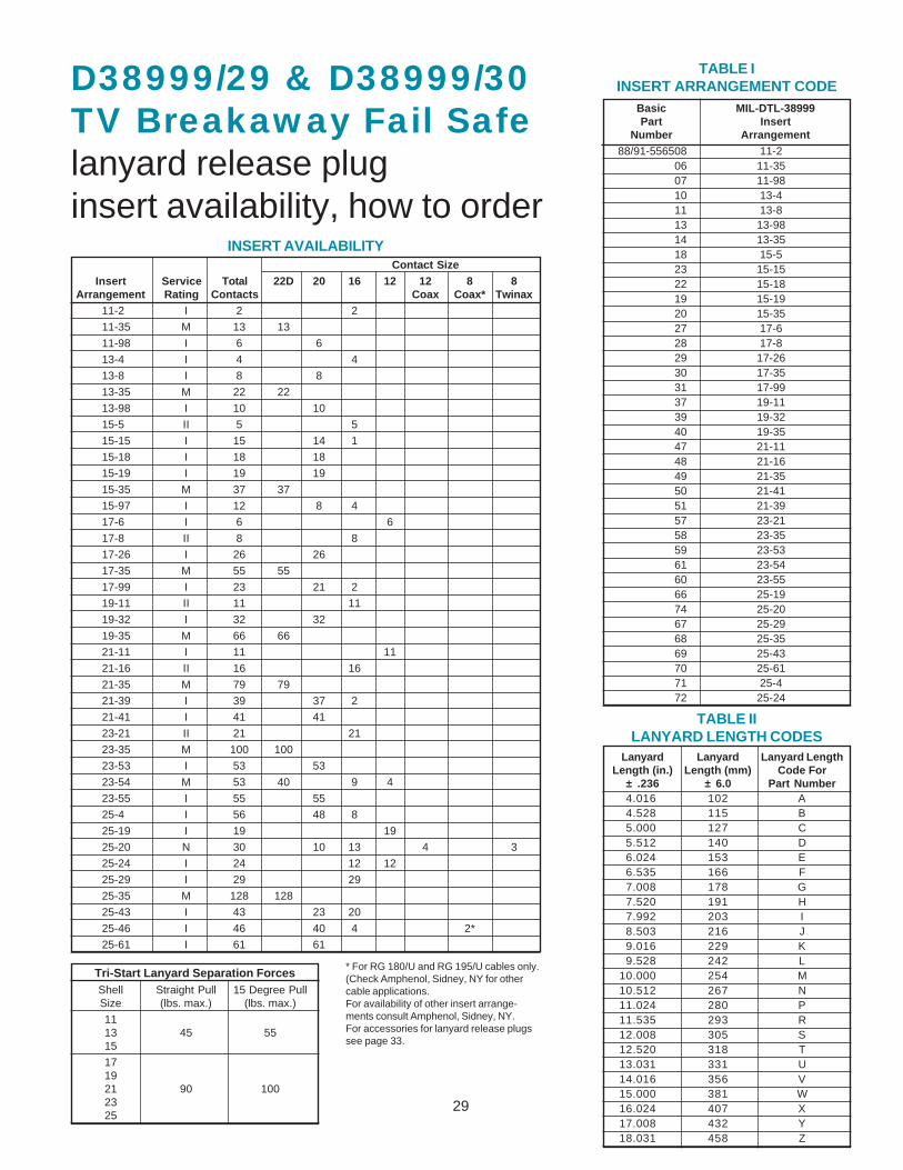
D38999/29 & D38999/30TV Breakaway Fail Safelanyard release pluginsert availability, how to order
Contact SizeInsert Service Total 22D 20 16 12 12 8 8
Arrangement Rating Contacts Coax Coax* Twinax11-2 I 2 2
11-35 M 13 13
11-98 I 6 6
13-4 I 4 4
13-8 I 8 8
13-35 M 22 22
13-98 I 10 10
15-5 II 5 5
15-15 I 15 14 1
15-18 I 18 18
15-19 I 19 19
15-35 M 37 37
15-97 I 12 8 4
17-6 I 6 6
17-8 II 8 8
17-26 I 26 26
17-35 M 55 55
17-99 I 23 21 2
19-11 II 11 11
19-32 I 32 32
19-35 M 66 66
21-11 I 11 11
21-16 II 16 16
21-35 M 79 79
21-39 I 39 37 2
21-41 I 41 41
23-21 II 21 21
23-35 M 100 100
23-53 I 53 53
23-54 M 53 40 9 4
23-55 I 55 55
25-4 I 56 48 8
25-19 I 19 19
25-20 N 30 10 13 4 3
25-24 I 24 12 12
25-29 I 29 29
25-35 M 128 128
25-43 I 43 23 20
25-46 I 46 40 4 2*
25-61 I 61 61
INSERT AVAILABILITY
* For RG 180/U and RG 195/U cables only.(Check Amphenol, Sidney, NY for othercable applications.For availability of other insert arrange-ments consult Amphenol, Sidney, NY.For accessories for lanyard release plugssee page 33.
TABLE IILANYARD LENGTH CODES
Basic MIL-DTL-38999Part Insert
Number Arrangement88/91-556508 11-2
06 11-3507 11-9810 13-411 13-813 13-9814 13-3518 15-523 15-1522 15-1819 15-1920 15-3527 17-628 17-829 17-2630 17-3531 17-9937 19-1139 19-3240 19-3547 21-1148 21-1649 21-3550 21-4151 21-3957 23-2158 23-3559 23-5361 23-5460 23-5566 25-1974 25-2067 25-2968 25-3569 25-4370 25-6171 25-472 25-24
Lanyard Lanyard Lanyard LengthLength (in.) Length (mm) Code For
± .236 ± 6.0 Part Number4.016 102 A4.528 115 B5.000 127 C5.512 140 D6.024 153 E6.535 166 F7.008 178 G7.520 191 H7.992 203 I8.503 216 J9.016 229 K9.528 242 L
10.000 254 M10.512 267 N11.024 280 P11.535 293 R12.008 305 S12.520 318 T13.031 331 U14.016 356 V15.000 381 W16.024 407 X17.008 432 Y18.031 458 Z
TABLE IINSERT ARRANGEMENT CODE
Tri-Start Lanyard Separation ForcesShell Straight Pull 15 Degree PullSize (lbs. max.) (lbs. max.)
1113 45 5515
171921 90 1002325
30
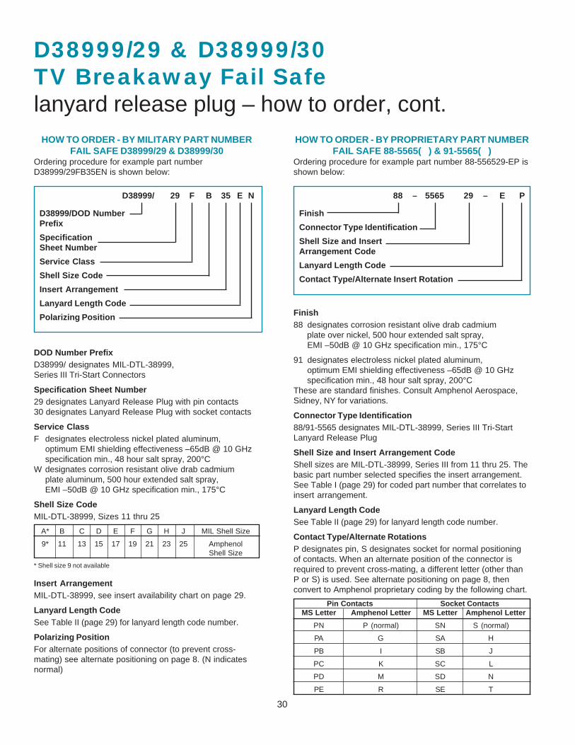
HOW TO ORDER - BY MILITARY PART NUMBERFAIL SAFE D38999/29 & D38999/30
Ordering procedure for example part numberD38999/29FB35EN is shown below:
D38999/ 29 F B 35 E N
D38999/DOD NumberPrefix
SpecificationSheet Number
Service Class
Shell Size Code
Insert Arrangement
Lanyard Length Code
Polarizing Position
DOD Number PrefixD38999/ designates MIL-DTL-38999,Series III Tri-Start Connectors
Specification Sheet Number29 designates Lanyard Release Plug with pin contacts30 designates Lanyard Release Plug with socket contacts
Service ClassF designates electroless nickel plated aluminum,
optimum EMI shielding effectiveness –65dB @ 10 GHzspecification min., 48 hour salt spray, 200°C
W designates corrosion resistant olive drab cadmiumplate aluminum, 500 hour extended salt spray,EMI –50dB @ 10 GHz specification min., 175°C
Shell Size CodeMIL-DTL-38999, Sizes 11 thru 25
A* B C D E F G H J MIL Shell Size
9* 11 13 15 17 19 21 23 25 AmphenolShell Size
* Shell size 9 not available
Insert ArrangementMIL-DTL-38999, see insert availability chart on page 29.
Lanyard Length CodeSee Table II (page 29) for lanyard length code number.
Polarizing PositionFor alternate positions of connector (to prevent cross-mating) see alternate positioning on page 8. (N indicatesnormal)
D38999/29 & D38999/30TV Breakaway Fail Safelanyard release plug – how to order, cont.
88 – 5565 29 – E P
Finish
Connector Type Identification
Shell Size and InsertArrangement Code
Lanyard Length Code
Contact Type/Alternate Insert Rotation
Finish88 designates corrosion resistant olive drab cadmium
plate over nickel, 500 hour extended salt spray, EMI –50dB @ 10 GHz specification min., 175°C
91 designates electroless nickel plated aluminum, optimum EMI shielding effectiveness –65dB @ 10 GHz specification min., 48 hour salt spray, 200°C
These are standard finishes. Consult Amphenol Aerospace,Sidney, NY for variations.
Connector Type Identification88/91-5565 designates MIL-DTL-38999, Series III Tri-StartLanyard Release Plug
Shell Size and Insert Arrangement CodeShell sizes are MIL-DTL-38999, Series III from 11 thru 25. Thebasic part number selected specifies the insert arrangement.See Table I (page 29) for coded part number that correlates toinsert arrangement.
Lanyard Length CodeSee Table II (page 29) for lanyard length code number.
Contact Type/Alternate RotationsP designates pin, S designates socket for normal positioningof contacts. When an alternate position of the connector isrequired to prevent cross-mating, a different letter (other thanP or S) is used. See alternate positioning on page 8, thenconvert to Amphenol proprietary coding by the following chart.
HOW TO ORDER - BY PROPRIETARY PART NUMBERFAIL SAFE 88-5565( ) & 91-5565( )
Ordering procedure for example part number 88-556529-EP isshown below:
Pin Contacts Socket ContactsMS Letter Amphenol Letter MS Letter Amphenol Letter
PN P (normal) SN S (normal)
PA G SA H
PB I SB J
PC K SC L
PD M SD N
PE R SE T
31
2.008 MAX�51.00 MAX
BLUE�BAND †�
1.687 MAX�42.85 MAX
2.030 MAX�51.56 MAX
**
.100 MAX�2.54 MAX�OUTER SLEEVE MOVEMENT�DURING UNMATING �THREAD RELEASE
2.000 MAX�50.80 MAX�ACCESS.�
DIA
LANYARD LENGTH�(See Lanyard Length Table)
METRIC �THREAD�M37X�1.0-6g0.100R
**2.000 MAX�50.80 MAX�ACCESS.�
DIA
.374 MAX�9.50 MAX�OUTER SLEEVE MOVEMENT�DURING UNMATING �THREAD RELEASE
.359 MAX�9.12 MAX
2.705 MAX�68.71 MAX
BLUE �BAND †�
1.781 MAX�45.24 MAX
2.375 MAX�60.33 MAX
LANYARD LENGTH�(See Lanyard Length Table)
METRIC�THREAD�M37X�1.0-6g�0.100R
.359 MAX�9.12 MAX
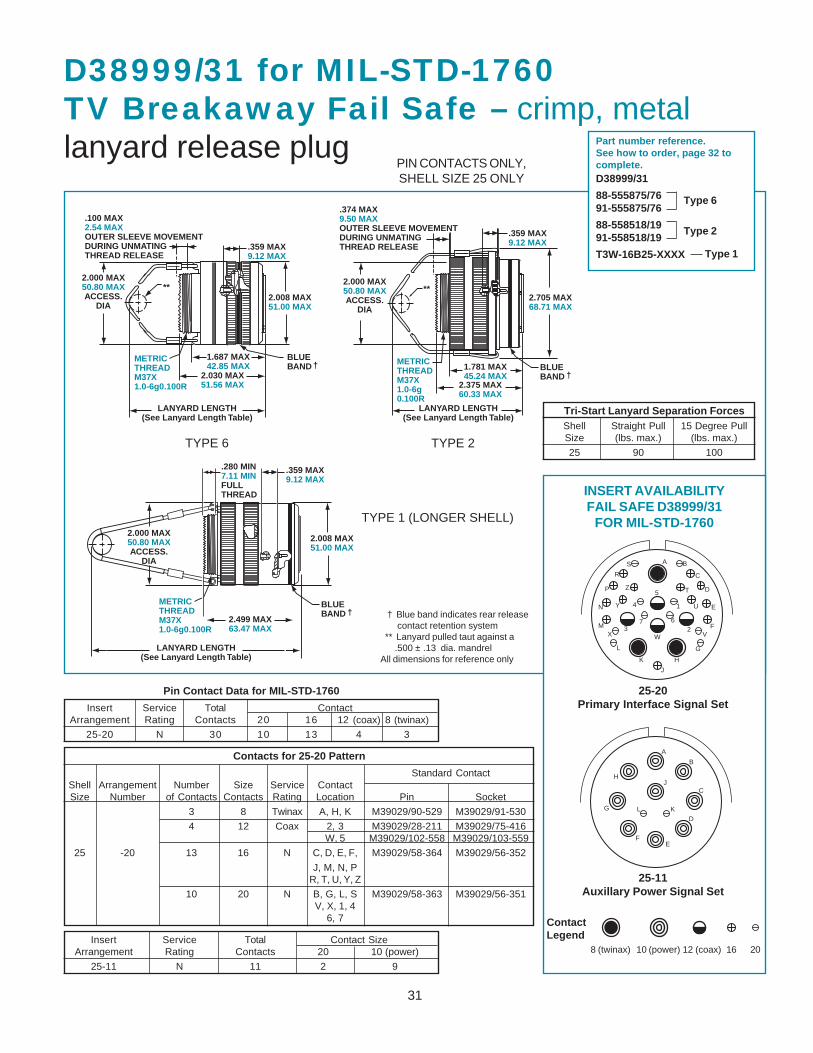
D38999/31 for MIL-STD-1760TV Breakaway Fail Safe – crimp, metallanyard release plug
TYPE 6 TYPE 2
Part number reference.See how to order, page 32 tocomplete.D38999/31
88-555875/7691-555875/76
88-558518/1991-558518/19
T3W-16B25-XXXX
Type 6
Type 2
† Blue band indicates rear release contact retention system** Lanyard pulled taut against a
.500 ± .13 dia. mandrelAll dimensions for reference only
PIN CONTACTS ONLY,SHELL SIZE 25 ONLY
BLUE �BAND †�
2.000 MAX�50.80 MAX�ACCESS.�
DIA
2.008 MAX�51.00 MAX
.359 MAX�9.12 MAX
METRIC �THREAD�M37X�1.0-6g0.100R
.280 MIN�7.11 MIN�FULL�THREAD���
LANYARD LENGTH�(See Lanyard Length Table)
2.499 MAX�63.47 MAX
TYPE 1 (LONGER SHELL)
Standard ContactShell Arrangement Number Size Service ContactSize Number of Contacts Contacts Rating Location Pin Socket
3 8 Twinax A, H, K M39029/90-529 M39029/91-530
4 12 Coax 2, 3 M39029/28-211 M39029/75-416W, 5 M39029/102-558 M39029/103-559
25 -20 13 16 N C, D, E, F, M39029/58-364 M39029/56-352
J, M, N, PR, T, U, Y, Z
10 20 N B, G, L, S M39029/58-363 M39029/56-351V, X, 1, 4
6, 7
Insert Service Total Contact SizeArrangement Rating Contacts 20 10 (power)
25-11 N 11 2 9
Insert Service Total ContactArrangement Rating Contacts 20 16 12 (coax) 8 (twinax)
25-20 N 30 10 13 4 3
Pin Contact Data for MIL-STD-1760
Contacts for 25-20 Pattern
A B
C
D
E
F
G
H
J
K
L
M
N
P
R
S
T
U
VWX
Y
Z
1
23
4
5
67
A
B
C
D
EF
G
HJ
KL
INSERT AVAILABILITYFAIL SAFE D38999/31
FOR MIL-STD-1760
25-20Primary Interface Signal Set
ContactLegend
8 (twinax) 10 (power) 12 (coax) 16 20
25-11Auxillary Power Signal Set
Type 1
Tri-Start Lanyard Separation ForcesShell Straight Pull 15 Degree PullSize (lbs. max.) (lbs. max.)
25 90 100
32
TABLE IIILANYARD LENGTH CODES
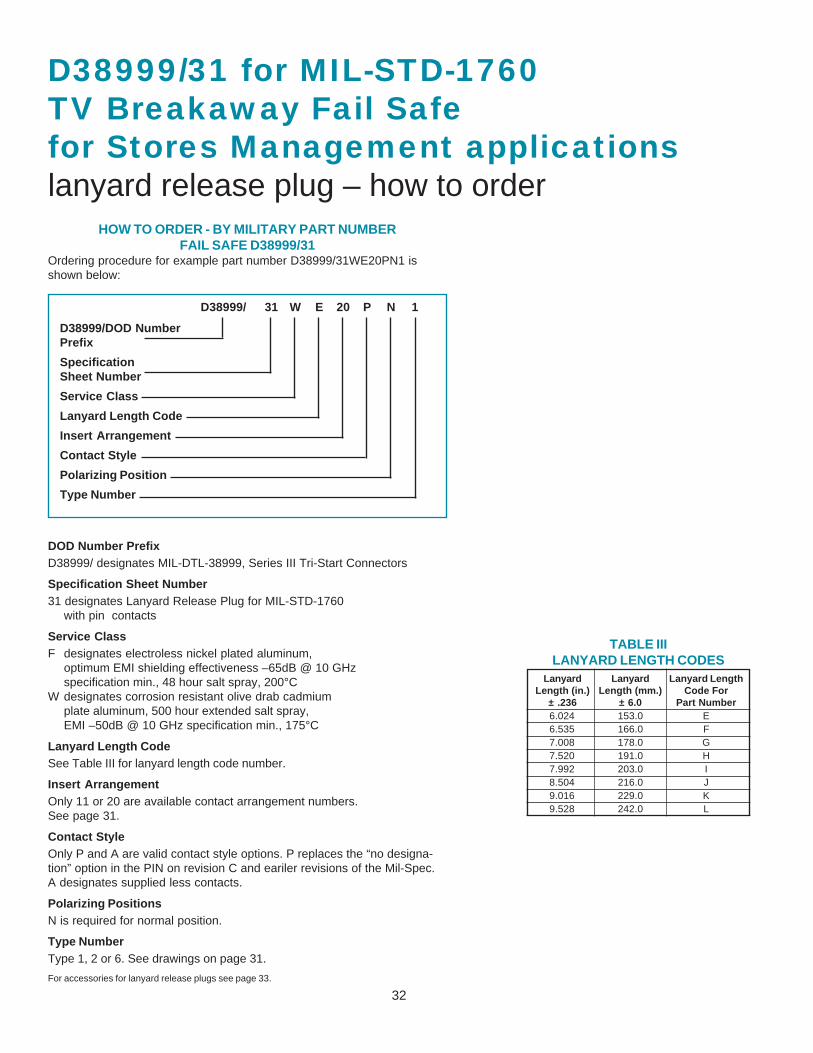
D38999/31 for MIL-STD-1760TV Breakaway Fail Safefor Stores Management applicationslanyard release plug – how to order
HOW TO ORDER - BY MILITARY PART NUMBERFAIL SAFE D38999/31
Ordering procedure for example part number D38999/31WE20PN1 isshown below:
D38999/ 31 W E 20 P N 1
D38999/DOD NumberPrefix
SpecificationSheet Number
Service Class
Lanyard Length Code
Insert Arrangement
Contact Style
Polarizing Position
Type Number
DOD Number PrefixD38999/ designates MIL-DTL-38999, Series III Tri-Start Connectors
Specification Sheet Number31 designates Lanyard Release Plug for MIL-STD-1760
with pin contacts
Service ClassF designates electroless nickel plated aluminum,
optimum EMI shielding effectiveness –65dB @ 10 GHzspecification min., 48 hour salt spray, 200°C
W designates corrosion resistant olive drab cadmiumplate aluminum, 500 hour extended salt spray,EMI –50dB @ 10 GHz specification min., 175°C
Lanyard Length CodeSee Table III for lanyard length code number.
Insert ArrangementOnly 11 or 20 are available contact arrangement numbers.See page 31.
Contact StyleOnly P and A are valid contact style options. P replaces the “no designa-tion” option in the PIN on revision C and eariler revisions of the Mil-Spec.A designates supplied less contacts.
Polarizing PositionsN is required for normal position.
Type NumberType 1, 2 or 6. See drawings on page 31.
For accessories for lanyard release plugs see page 33.
Lanyard Lanyard Lanyard LengthLength (in.) Length (mm.) Code For
± .236 ± 6.0 Part Number6.024 153.0 E6.535 166.0 F7.008 178.0 G7.520 191.0 H7.992 203.0 I8.504 216.0 J9.016 229.0 K9.528 242.0 L
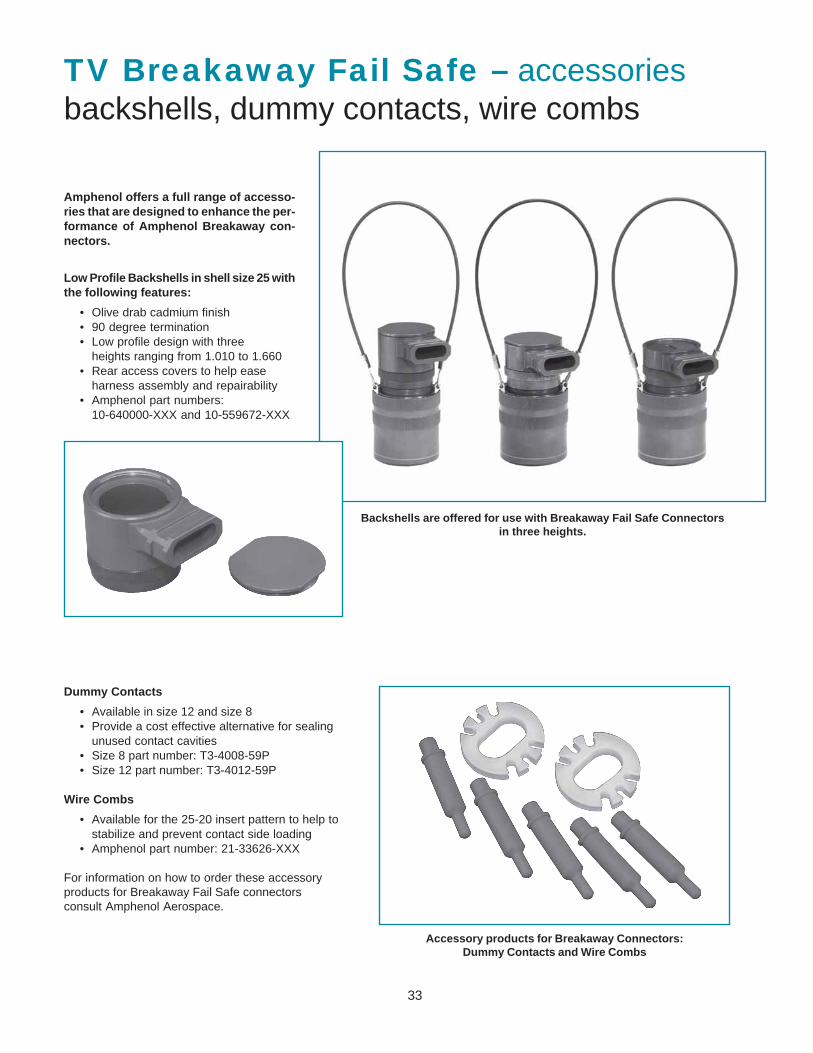
33
TV Breakaway Fail Safe – accessoriesbackshells, dummy contacts, wire combs
Amphenol offers a full range of accesso-ries that are designed to enhance the per-formance of Amphenol Breakaway con-nectors.
Low Profile Backshells in shell size 25 withthe following features:
• Olive drab cadmium finish• 90 degree termination• Low profile design with three
heights ranging from 1.010 to 1.660• Rear access covers to help ease
harness assembly and repairability• Amphenol part numbers:
10-640000-XXX and 10-559672-XXX
Backshells are offered for use with Breakaway Fail Safe Connectorsin three heights.
Dummy Contacts
• Available in size 12 and size 8• Provide a cost effective alternative for sealing
unused contact cavities• Size 8 part number: T3-4008-59P• Size 12 part number: T3-4012-59P
Wire Combs
• Available for the 25-20 insert pattern to help tostabilize and prevent contact side loading
• Amphenol part number: 21-33626-XXX
For information on how to order these accessoryproducts for Breakaway Fail Safe connectorsconsult Amphenol Aerospace.
Accessory products for Breakaway Connectors:Dummy Contacts and Wire Combs
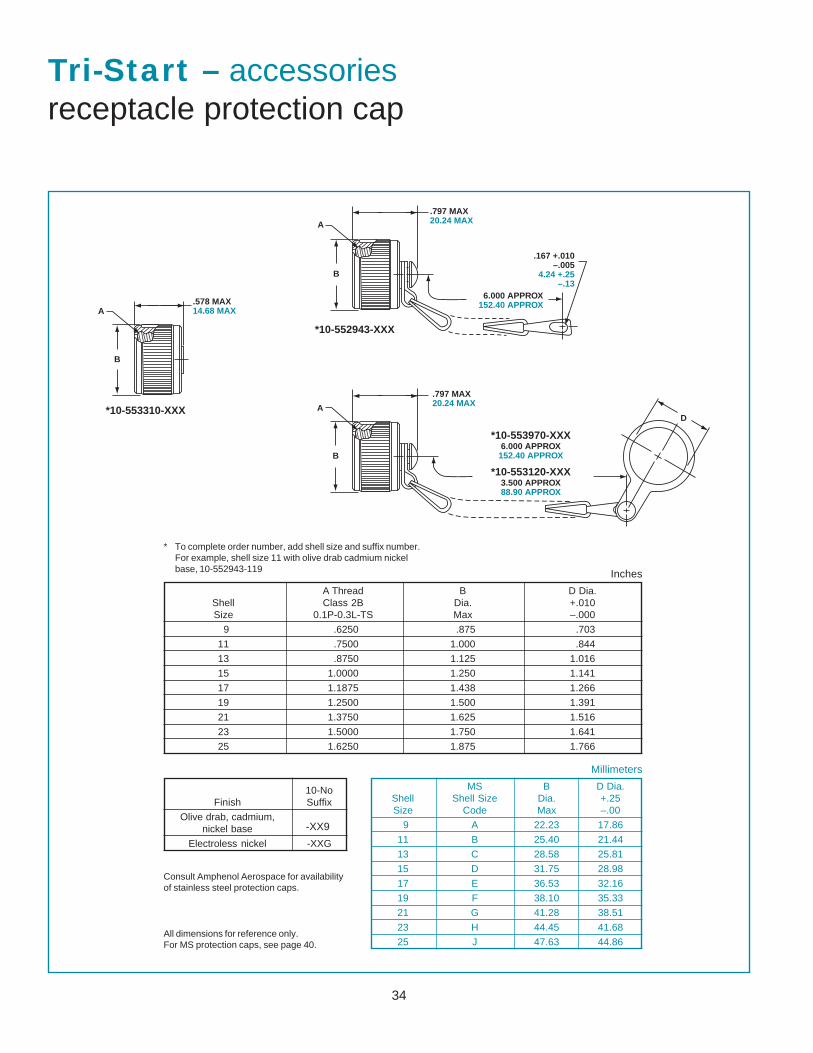
34
B
A.578 MAX�14.68 MAX
B
A
.167 +.010��–.005�
4.24 +.25��–.13
6.000 APPROX�152.40 APPROX
.797 MAX�20.24 MAX
B
A
.797 MAX�20.24 MAX
D
6.000 APPROX�152.40 APPROX
*10-553310-XXX
*10-552943-XXX
*10-553970-XXX
3.500 APPROX�88.90 APPROX
*10-553120-XXX
Tri-Start – accessoriesreceptacle protection cap
A Thread B D Dia.Shell Class 2B Dia. +.010Size 0.1P-0.3L-TS Max –.000
9 .6250 .875 .703
11 .7500 1.000 .844
13 .8750 1.125 1.016
15 1.0000 1.250 1.141
17 1.1875 1.438 1.266
19 1.2500 1.500 1.391
21 1.3750 1.625 1.516
23 1.5000 1.750 1.641
25 1.6250 1.875 1.766
Millimeters
Inches
10-NoFinish Suffix
Olive drab, cadmium,nickel base
Electroless nickel -XXG
-XX9
MS B D Dia.Shell Shell Size Dia. +.25Size Code Max –.00
9 A 22.23 17.86
11 B 25.40 21.44
13 C 28.58 25.81
15 D 31.75 28.98
17 E 36.53 32.16
19 F 38.10 35.33
21 G 41.28 38.51
23 H 44.45 41.68
25 J 47.63 44.86
Consult Amphenol Aerospace for availabilityof stainless steel protection caps.
* To complete order number, add shell size and suffix number.For example, shell size 11 with olive drab cadmium nickelbase, 10-552943-119
All dimensions for reference only.For MS protection caps, see page 40.
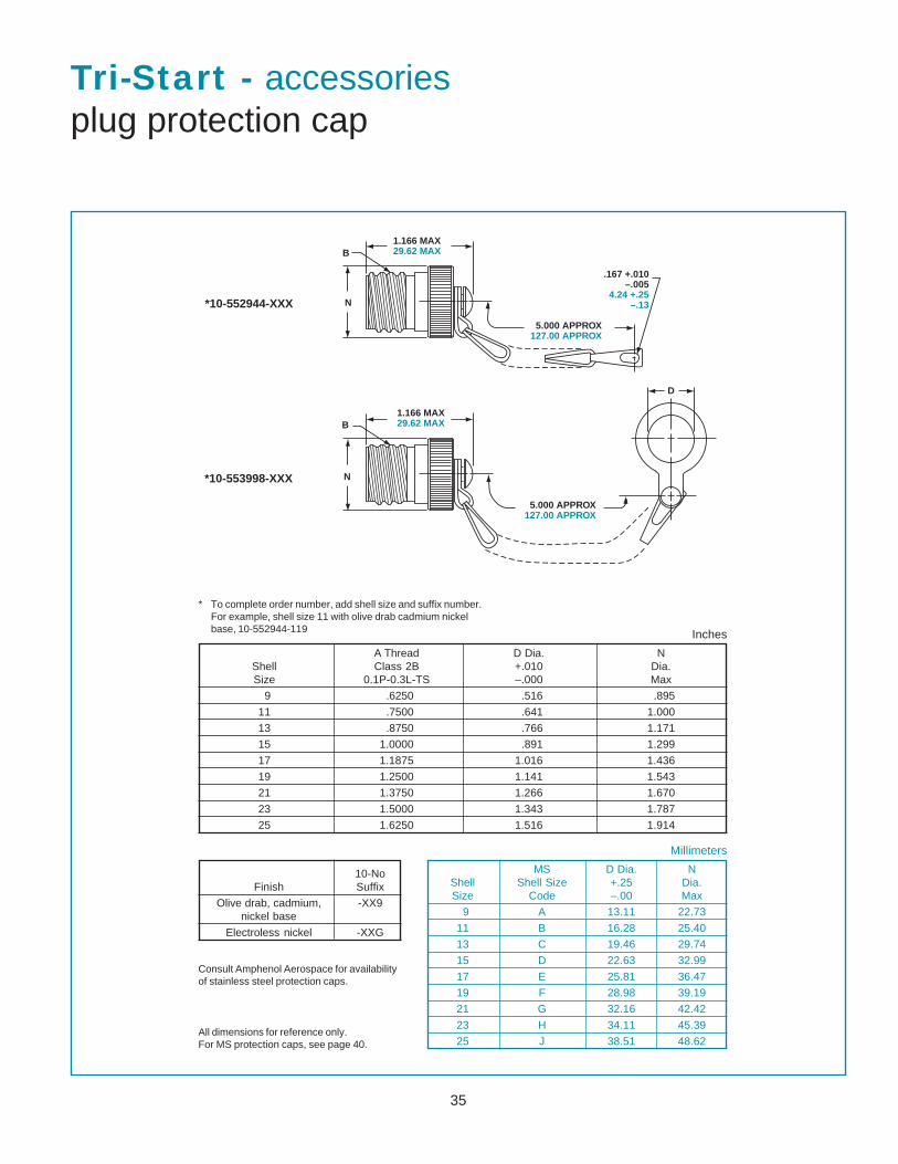
35
.167 +.010�–.005�
4.24 +.25�–.13
5.000 APPROX�127.00 APPROX
N
B1.166 MAX�29.62 MAX
5.000 APPROX�127.00 APPROX
N
B1.166 MAX�29.62 MAX
D
*10-552944-XXX
*10-553998-XXX
A Thread D Dia. NShell Class 2B +.010 Dia.Size 0.1P-0.3L-TS –.000 Max
9 .6250 .516 .895
11 .7500 .641 1.000
13 .8750 .766 1.171
15 1.0000 .891 1.299
17 1.1875 1.016 1.436
19 1.2500 1.141 1.543
21 1.3750 1.266 1.670
23 1.5000 1.343 1.787
25 1.6250 1.516 1.914
* To complete order number, add shell size and suffix number.For example, shell size 11 with olive drab cadmium nickelbase, 10-552944-119
Tri-Start - accessoriesplug protection cap
Inches
10-NoFinish Suffix
Olive drab, cadmium, -XX9nickel base
Electroless nickel -XXG
All dimensions for reference only.For MS protection caps, see page 40.
Consult Amphenol Aerospace for availabilityof stainless steel protection caps.
Millimeters
MS D Dia. NShell Shell Size +.25 Dia.Size Code –.00 Max
9 A 13.11 22.73
11 B 16.28 25.40
13 C 19.46 29.74
15 D 22.63 32.99
17 E 25.81 36.47
19 F 28.98 39.19
21 G 32.16 42.42
23 H 34.11 45.39
25 J 38.51 48.62

36
Tri-Start – accessoriesdummy receptacle
B ThreadMS Class 2A M T TT
Shell Shell Size 0.1P-0.3L-TS +.020 R1 R2 S +.008 W +.008Size Coded (Plated) –.000 ±.010 –.006 ±.010 –.006
9 A .6250 .822 .719 .594 .938 .128 .098 .216
11 B .7500 .822 .812 .719 1.031 .128 .098 .194
13 C .8750 .822 .906 .812 1.125 .128 .098 .194
15 D 1.0000 .822 .969 .906 1.219 .128 .098 .173
17 E 1.1875 .822 1.062 .969 1.312 .128 .098 .194
19 F 1.2500 .822 1.156 1.062 1.438 .128 .098 .194
21 G 1.3750 .791 1.250 1.156 1.562 .128 .125 .194
23 H 1.5000 .791 1.375 1.250 1.688 .154 .125 .242
25 J 1.6250 .791 1.500 1.375 1.812 .154 .125 .242
Millimeters
Inches
10-NoFinish Suffix
Olive drab, cadmium,nickel base
Electroless nickel -XXG
-XX9
* To complete order number, add shell size and suffix number.For example, shell size 11 with olive drab cadmium nickelbase, 10-553974-119
MS M T TTShell Shell Size +.51 R1 R2 S +.20 W +.20Size Code –.00 ±.25 –.15 ±.25 –.15
9 A 20.88 18.26 15.09 23.83 3.25 2.49 5.49
11 B 20.88 20.62 18.26 26.19 3.25 2.49 4.93
13 C 20.88 23.01 20.62 28.58 3.25 2.49 4.93
15 D 20.88 24.61 23.01 30.96 3.25 2.49 4.93
17 E 20.88 26.97 24.61 33.32 3.25 2.49 4.93
19 F 20.88 29.36 26.97 36.53 3.25 2.49 4.93
21 G 20.09 31.75 29.36 39.67 3.25 3.18 4.93
23 H 20.09 34.93 31.75 42.88 3.91 3.18 6.15
25 J 20.09 38.10 34.93 46.02 3.91 3.18 6.15
M
M
.005
.13
T�4 PLACES
TT�4 PLACES
S�2 PLACES
2 PLACES
2 PLACES
R1
R2
B THREAD
MW
All dimensions for reference only Designates true position dimensioning
Part number reference.See note below to complete.
* 10-553974-XXX
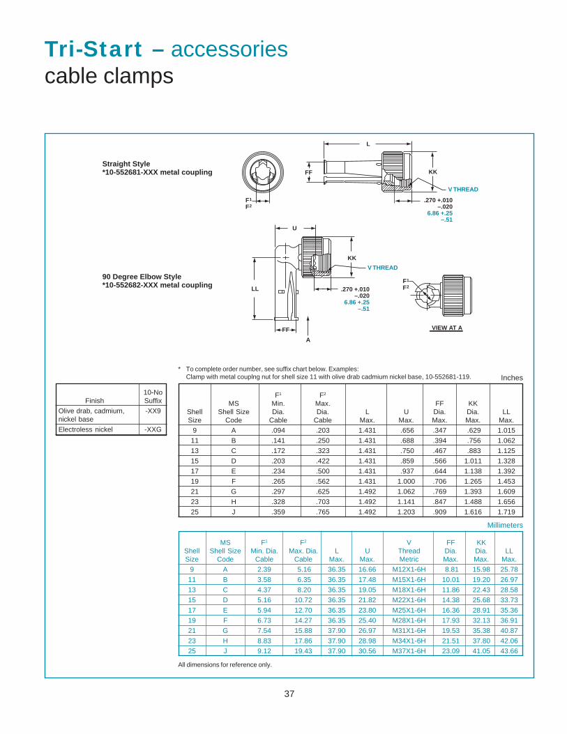
37
Tri-Start – accessoriescable clamps
* To complete order number, see suffix chart below. Examples:Clamp with metal couplng nut for shell size 11 with olive drab cadmium nickel base, 10-552681-119.
10-NoFinish Suffix
Olive drab, cadmium, -XX9nickel base
Electroless nickel -XXG
F1 F2
MS Min. Max. FF KKShell Shell Size Dia. Dia. L U Dia. Dia. LLSize Code Cable Cable Max. Max. Max. Max. Max.
9 A .094 .203 1.431 .656 .347 .629 1.015
11 B .141 .250 1.431 .688 .394 .756 1.062
13 C .172 .323 1.431 .750 .467 .883 1.125
15 D .203 .422 1.431 .859 .566 1.011 1.328
17 E .234 .500 1.431 .937 .644 1.138 1.392
19 F .265 .562 1.431 1.000 .706 1.265 1.453
21 G .297 .625 1.492 1.062 .769 1.393 1.609
23 H .328 .703 1.492 1.141 .847 1.488 1.656
25 J .359 .765 1.492 1.203 .909 1.616 1.719
MS F1 F2 V FF KKShell Shell Size Min. Dia. Max. Dia. L U Thread Dia. Dia. LLSize Code Cable Cable Max. Max. Metric Max. Max. Max.
9 A 2.39 5.16 36.35 16.66 M12X1-6H 8.81 15.98 25.78
11 B 3.58 6.35 36.35 17.48 M15X1-6H 10.01 19.20 26.97
13 C 4.37 8.20 36.35 19.05 M18X1-6H 11.86 22.43 28.58
15 D 5.16 10.72 36.35 21.82 M22X1-6H 14.38 25.68 33.73
17 E 5.94 12.70 36.35 23.80 M25X1-6H 16.36 28.91 35.36
19 F 6.73 14.27 36.35 25.40 M28X1-6H 17.93 32.13 36.91
21 G 7.54 15.88 37.90 26.97 M31X1-6H 19.53 35.38 40.87
23 H 8.83 17.86 37.90 28.98 M34X1-6H 21.51 37.80 42.06
25 J 9.12 19.43 37.90 30.56 M37X1-6H 23.09 41.05 43.66
Millimeters
Inches
All dimensions for reference only.
FF
L
KK
V THREAD
.270 +.010�–.020�
6.86 +.25�–.51
.270 +.010�–.020�
6.86 +.25�–.51
V THREAD
KK
FF
LL
U
VIEW AT A
F1
F2
F1
F2
�
A
Straight Style�*10-552681-XXX metal coupling
90 Degree Elbow Style�*10-552682-XXX metal coupling
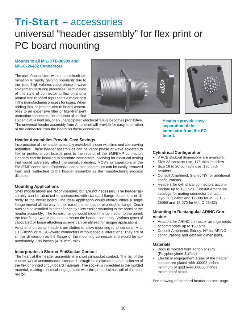
38
Tri-Start – accessoriesuniversal “header assembly” for flex print orPC board mountingMounts to all MIL-DTL-38999 andMIL-C-26482 Connectors
The use of connectors with printed circuit ter-mination is rapidly gaining popularity due tothe rise of high volume, vapor phase or wavesolder manufacturing processes. Terminationof this style of connector to flex print or aprinted circuit board represents a major costin the manufacturing process for users. Whenadding flex or printed circuit board assem-blies to an expensive filter or filter/transientprotection connector, the total cost of a failedsolder joint, a bent pin, or an unanticipated electrical failure becomes prohibitive.The universal header assembly from Amphenol will provide for easy separationof the connector from the board on these occasions.
Header Assemblies Provide Cost SavingsIncorporation of the header assembly provides the user with time and cost savingpotentials. These header assemblies can be vapor phase or wave soldered toflex or printed circuit boards prior to the receipt of the EMI/EMP connector.Headers can be installed to standard connectors, allowing for electrical testingthat would adversely affect the sensitive diodes, MOV’s or capacitors in theEMI/EMP connectors. Expensive connector assemblies can be easily removedfrom and reattached to the header assembly as the manufacturing processdictates.
Mounting ApplicationsShell modifications are recommended, but are not necessary. The header as-sembly can be attached to connectors with standard flange placement or di-rectly to the circuit board. The ideal application would involve either a singleflange moved all the way to the rear of the connector or a double flange. Cinchnuts can be installed in either flange to allow easier mounting to the panel or theheader assembly. The forward flange would mount the connector to the panel;the rear flange would be used to mount the header assembly. Various types ofcaptivated or loose attaching screws can be utilized for unique applications.Amphenol universal headers are slotted to allow mounting to all series of MIL-DTL-38999 or MIL-C-26482 connectors without special alterations. They are ofsimilar dimension as the flange of the mounting connector and would be ap-proximately .185 inches (4.70 mm) thick.
Incorporates a Shorter Pin/Socket ContactThe heart of the header assembly is a short pin/socket contact. The tail of thecontact would accommodate standard through-hole diameters and thickness ofthe flex or printed circuit board materials. The socket is imbedded in the moldedmaterial, making electrical engagement with the printed circuit tail of the con-nector.
Cylindrical Configuration• 3 PCB stickout dimensions are available.• Size 22 contacts use .175 thick headers• Size 16 to 20 contacts use .195 thick
headers• Consult Amphenol, Sidney NY for additional
configurations.• Headers for cylindrical connectors accom-
modate up to 128 pins. Consult Amphenolcatalogs for mating connector contactlayouts (12-092 and 12-090 for MIL-DTL-38999 and 12-070 for MIL-C-26482)
Mounting to Rectangular ARINC Con-nectors• Headers for ARINC connector arrangements
accommodate up to 150 pins• Consult Amphenol, Sidney, NY for ARINC
configurations and detailed dimensions.
Materials• Body is molded from Torlon or PPS
(Polyphenylene Sulfide)• Electrical engagement areas of the header
contact are plated with .00003 inchesminimum of gold over .00005 inchesminimum of nickel.
See drawing of standard header on next page.
Headers provide easyseparation of theconnector from the PCboard.
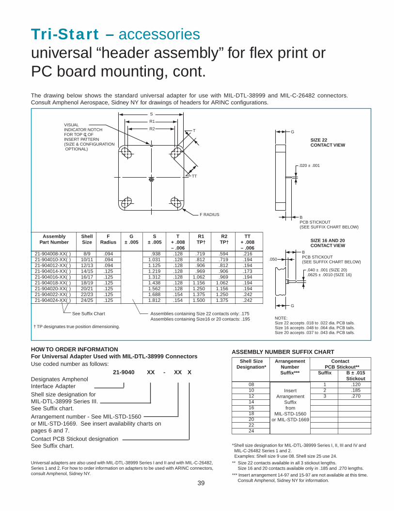
39
R2
R1
S
T
TT
VISUALINDICATOR NOTCHFOR TOP C OFINSERT PATTERN(SIZE & CONFIGURATION OPTIONAL)
L
F RADIUSBPCB STICKOUT(SEE SUFFIX CHART BELOW)
G
.020 ± .001
.040 ± .001 (SIZE 20)
.0625 ± .0010 (SIZE 16)
BPCB STICKOUT(SEE SUFFIX CHART BELOW)
.050
G
SIZE 22 CONTACT VIEW
SIZE 16 AND 20CONTACT VIEW
NOTE:Size 22 accepts .018 to .022 dia. PCB tails.Size 16 accepts .048 to .064 dia. PCB tails.Size 20 accepts .037 to .043 dia. PCB tails.
Tri-Start – accessoriesuniversal “header assembly” for flex print orPC board mounting, cont.The drawing below shows the standard universal adapter for use with MIL-DTL-38999 and MIL-C-26482 connectors.Consult Amphenol Aerospace, Sidney NY for drawings of headers for ARINC configurations.
Assembly Shell F G S T R1 R2 TTPart Number Size Radius ± .005 ± .005 + .008 TP† TP† + .008
– .006 – .00621-904008-XX( ) 8/9 .094 .938 .128 .719 .594 .21621-904010-XX( ) 10/11 .094 1.031 .128 .812 .719 .19421-904012-XX( ) 12/13 .094 1.125 .128 .906 .812 .19421-904014-XX( ) 14/15 .125 1.219 .128 .969 .906 .17321-904016-XX( ) 16/17 .125 1.312 .128 1.062 .969 .19421-904018-XX( ) 18/19 .125 1.438 .128 1.156 1.062 .19421-904020-XX( ) 20/21 .125 1.562 .128 1.250 1.156 .19421-904022-XX( ) 22/23 .125 1.688 .154 1.375 1.250 .24221-904024-XX( ) 24/25 .125 1.812 .154 1.500 1.375 .242
Assemblies containing Size 22 contacts only: .175Assemblies containing Size16 or 20 contacts: .195
See Suffix Chart
† TP designates true position dimensioning.
ASSEMBLY NUMBER SUFFIX CHART
Shell Size Arrangement ContactDesignation* Number PCB Stickout**
Suffix*** Suffix B ± .015Stickout
08 1 .12010 2 .18512 3 .270141618202224
InsertArrangement
Suffixfrom
MIL-STD-1560or MIL-STD-1669
HOW TO ORDER INFORMATIONFor Universal Adapter Used with MIL-DTL-38999 ConnectorsUse coded number as follows:
21-9040 XX - XX XDesignates AmphenolInterface AdapterShell size designation forMIL-DTL-38999 Series III.See Suffix chart.Arrangement number - See MIL-STD-1560or MIL-STD-1669. See insert availability charts onpages 6 and 7.Contact PCB Stickout designationSee Suffix chart.
Universal adapters are also used with MIL-DTL-38999 Series I and II and with MIL-C-26482,Series 1 and 2. For how to order information on adapters to be used with ARINC connectors,consult Amphenol, Sidney NY.
*Shell size designation for MIL-DTL-38999 Series I, II, III and IV and MIL-C-26482 Series 1 and 2. Examples: Shell size 9 use 08. Shell size 25 use 24.
** Size 22 contacts available in all 3 stickout lengths. Size 16 and 20 contacts available only in .185 and .270 lengths.
*** Insert arrangement 14-97 and 15-97 are not available at this time. Consult Amphenol, Sidney NY for information.
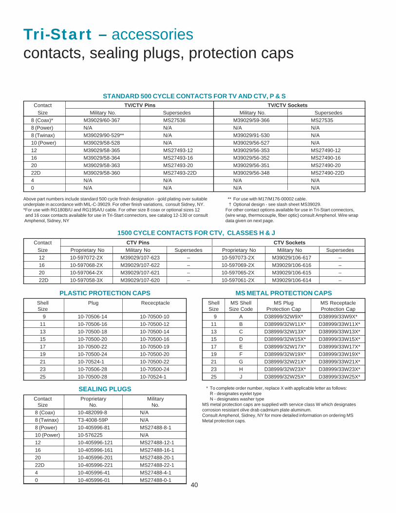
40
Tri-Start – accessoriescontacts, sealing plugs, protection caps
STANDARD 500 CYCLE CONTACTS FOR TV AND CTV, P & SContact TV/CTV Pins TV/CTV Sockets
Size Military No. Supersedes Military No. Supersedes
8 (Coax)* M39029/60-367 MS27536 M39029/59-366 MS27535
8 (Power) N/A N/A N/A N/A
8 (Twinax) M39029/90-529** N/A M39029/91-530 N/A
10 (Power) M39029/58-528 N/A M39029/56-527 N/A
12 M39029/58-365 MS27493-12 M39029/56-353 MS27490-12
16 M39029/58-364 MS27493-16 M39029/56-352 MS27490-16
20 M39029/58-363 MS27493-20 M39029/56-351 MS27490-20
22D M39029/58-360 MS27493-22D M39029/56-348 MS27490-22D
4 N/A N/A N/A N/A
0 N/A N/A N/A N/A
1500 CYCLE CONTACTS FOR CTV, CLASSES H & JContact CTV Pins CTV Sockets
Size Proprietary No Military No Supersedes Proprietary No Military No Supersedes
12 10-597072-2X M39029/107-623 – 10-597073-2X M39029/106-617 –
16 10-597068-2X M39029/107-622 – 10-597069-2X M39029/106-616 –
20 10-597064-2X M39029/107-621 – 10-597065-2X M39029/106-615 –
22D 10-597058-3X M39029/107-620 – 10-597061-2X M39029/106-614 –
PLASTIC PROTECTION CAPS MS METAL PROTECTION CAPS
SEALING PLUGS
Shell Plug RececptacleSize
9 10-70506-14 10-70500-10
11 10-70506-16 10-70500-12
13 10-70500-18 10-70500-14
15 10-70500-20 10-70500-16
17 10-70500-22 10-70500-19
19 10-70500-24 10-70500-20
21 10-70524-1 10-70500-22
23 10-70506-28 10-70500-24
25 10-70500-28 10-70524-1
Contact Proprietary MilitarySize No. No.
8 (Coax) 10-482099-8 N/A
8 (Twinax) T3-4008-59P N/A
8 (Power) 10-405996-81 MS27488-8-1
10 (Power) 10-576225 N/A
12 10-405996-121 MS27488-12-1
16 10-405996-161 MS27488-16-1
20 10-405996-201 MS27488-20-1
22D 10-405996-221 MS27488-22-1
4 10-405996-41 MS27488-4-1
0 10-405996-01 MS27488-0-1
Above part numbers include standard 500 cycle finish designation - gold plating over suitableunderplate in accordance with MIL-C-39029. For other finish variations, consult Sidney, NY.*For use with RG180B/U and RG195A/U cable. For other size 8 coax or optional sizes 12 and 16 coax contacts available for use in Tri-Start connectors, see catalog 12-130 or consult Amphenol, Sidney, NY
* To complete order number, replace X with applicable letter as follows:R - designates eyelet typeN - designates washer type
MS metal protection caps are supplied with service class W which designatescorrosion resistant olive drab cadmium plate aluminum.Consult Amphenol, Sidney, NY for more detailed information on ordering MSMetal protection caps.
Shell MS Shell MS Plug MS ReceptacleSize Size Code Protection Cap Protection Cap
9 A D38999/32W9X* D38999/33W9X*
11 B D38999/32W11X* D38999/33W11X*
13 C D38999/32W13X* D38999/33W13X*
15 D D38999/32W15X* D38999/33W15X*
17 E D38999/32W17X* D38999/33W17X*
19 F D38999/32W19X* D38999/33W19X*
21 G D38999/32W21X* D38999/33W21X*
23 H D38999/32W23X* D38999/33W23X*
25 J D38999/32W25X* D38999/33W25X*
** For use with M17/M176-00002 cable.† Optional design - see slash sheet MS39029.
For other contact options available for use in Tri-Start connectors,(wire wrap, thermocouple, fiber optic) consult Amphenol. Wire wrapdata given on next page.

41
SOCKETS PINS Contact Stickout Max/Min (See Illustration below)
PCB D38999/24Socket Tail D38999/20 D38999/26 TV07
Contacts Size Dia TVP00 TV06 Metal Composite10-497623-15 22D .019 .291 .316 .285 .242
.226 .251 .222 .18210-497623-25 22D .019 .868 .893 .862 .819
.803 .828 .802 .75910-497623-35 22D .019 .348 .373 .342 .299
.283 .308 .282 .23910-497623-45 22D .019 .208 .233 .202 .159
.143 .168 .142 .09910-497623-75 22D .019 .146 .171 .140 .097
.081 .106 .080 .03710-497623-105 22D .019 .028 .053 .022 .021
NS .000 NS NS10-497623-145 22D .019 .609 .634 .603 .560
.539 .564 .538 .49510-497623-155 22D .019 .423 .448 .417 .374
.358 .383 .357 .31410-497643-15 20 .019 .348 .373 .342 .299
.294 .319 .293 .25010-497643-25 20 .019 .213 .238 .207 .164
.159 .184 .158 .11510-497643-35 20 .019 .555 .580 .549 .506
.501 .526 .500 .45710-497643-45 20 .019 .138 .163 .132 .089
.084 .109 .083 .04010-497650-15 16 .040 .255 .280 .249 .206
.201 .226 .200 .157Wire Wrap TailContacts Square
10-497577-15 22D .025 .155 .180 .149 .106.090 .115 .089 .046
10-497577-25 22D .025 .002 .027 NS NSNS NS NS NS
10-897577-35 22D .025 .201 .226 .195 .152.136 .161 .135 .092
10-497577-55 22D .025 .566 .591 .560 .517.501 .526 .500 .457
10-497621-15 20 .025 .151 .176 .145 .102.101 .126 .100 .057
10-497621-25 20 .025 .605 .630 .599 .556.555 .580 .554 .511
10-497621-35 20 .025 .308 .333 .302 .259.258 .283 .257 .214
Contact Stickout Max/Min (See Illustration below)
PCB D38999/24Pin Tail D38999/20 D38999/26 TV07
Contacts Size Dia TVP00 TV06 Metal Composite10-407552-15 22M .019 .335 .360 .329 .286
.280 .305 .279 .23610-407552-55 22M .019 .224 .249 .218 .175
.169 .194 .168 .12510-407552-85 22M .019 .060 .085 .054 .011
.010 .035 .009 NS10-407552-95 22M .019 NS NS NS NS
10-407552-115 22M .019 .002 .023 NS NSNS NS
10-497640-15 20 .019 .348 .373 .342 .299.298 .323 .297 .254
10-497640-25 20 .019 .213 .238 .207 .164.163 .188 .162 .119
10-497640-45 20 .019 NS NS NS NS
10-497640-65 20 .019 .138 .163 .132 .089.088 .113 .087 .044
10-497596-15 20 .025 .058 .083 .052 .009.012 .037 .011 NS
10-497596-25 20 .025 .148 .173 .142 .099.102 .127 .101 .058
10-497596-35 20 .025 .229 .254 .223 .180.183 .208 .182 .139
10-497596-55 20 .025 .346 .371 .340 .297.300 .325 .299 .256
10-497695-15 16 .040 .255 .280 .249 .206.205 .230 .204 .161
10-497630-25 16 .062 .348 .373 .342 .299.298 .323 .297 .254
10-497630-35 16 .062 .060 .085 .054 .011.010 .035 .009 NS
10-497630-45 16 .062 .108 .133 .102 .059.062 .087 .061 .018
10-597502-15 12 .081 .228 .252 .222 .179.178 .203 .177 .134
Wire Wrap TailContacts Square
10-407572-15 22D .025 .014 .498 .008 NSNS .007 NS NS
10-407572-35 22D .025 .155 .180 .149 .106.105 .130 .104 .061
10-407572-45 22D .025 .255 .280 .249 .206.205 .230 .204 .161
10-407572-75 22D .025 .521 .546 .515 .472.475 .500 .474 .431
10-407584-25 20 .025 .605 .630 .599 .556.559 .584 .558 .515
10-407584-35 20 .025 .308 .333 .302 .259.262 .287 .261 .218
All dimensions for reference only.Consult Sidney, NY for specific contactcontour stickout data.NS designates No Stickout.
See also catalog 12-170, AmphenolCylindrical Connectors for PCBApplications. This catalog provides themost commonly used insert patternpin-out drawings which have beentooled for the purpose of attachingcylindrical connectors to printed circuitboards.
PCB Socket and pin part numbers include finish designation - gold plating oversuitable underplate in accordance with MIL-C-39029. For other finish variations,consult Amphenol, Sidney, NY.Note: 22M and 22D contacts are interchangeable.For other contact options available for use in Tri-Start connectors (thermocouple,fiber optic), consult Amphenol, Sidney, NY.
Tri-Startcontacts – printed circuit board, wire wrap
CONTACT�STICK OUT MAX/MIN
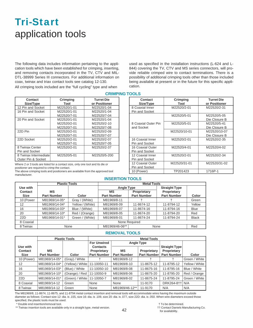
42
Where 2 or 3 tools are listed for a contact size, only one tool and its die orpositioner are required to crimp the contact.The above crimping tools and positioners are available from the approved toolmanufacturer.
Tri-Startapplication tools
The following data includes information pertaining to the appli-cation tools which have been established for crimping, inserting,and removing contacts incorporated in the TV, CTV and MIL-DTL-38999 Series III connectors. For additional information oncoax, twinax and triax contact tools see catalog 12-130.All crimping tools included are the “full cycling” type and when
used as specified in the installation instructions (L-624 and L-844) covering the TV, CTV and MS series connectors, will pro-vide reliable crimped wire to contact terminations. There is apossibility of additional crimping tools other than those includedbeing available at present or in the future for this specific appli-cation.
CRIMPING TOOLS
INSERTION TOOLS
REMOVAL TOOLS
Contact Crimping Turret DieSize/Type Tool or Positioner
12 Pin and Socket M22520/1-01 M22520/1-0416 Pin and Socket M22520/1-01 M22520/1-04
M22520/7-01 M22520/7-0420 Pin and Socket M22520/1-01 M22520/1-04
M22520/2-01 M22520/2-10M22520/7-01 M22520/7-08
22D Pin M22520/2-01 M22520/2-09M22520/7-01 M22520/7-07
22D Socket M22520/2-01 M22520/2-07M22520/7-01 M22520/7-05
8 Twinax Center M22520/2-01 M22520/2-37Pin and Socket8 Twinax Intermediate M22520/5-01 M22520/5-200Outer Pin & Socket
Contact Crimping Turret DieSize/Type Tool or Positioner
8 Coaxial Inner M22520/2-01 M22520/2-31Pin and Socket
M22520/5-01 M22520/5-05Die Closure B
8 Coaxial Outer Pin M22520/5-01 M22520/5-41and Socket Die Closure B
M22520/10-01 M22520/10-07Die Closure B
16 Coaxial Inner M22520/2-01 M22520/2-35Pin and Socket16 Coaxial Outer M22520/4-01 M22520/4-02Pin and Socket12 Coaxial Inner M22520/2-01 M22520/2-34Pin and Socket12 Coaxial Outer M22520/31-01 M22520/31-02Pin and Socket10 (Power) TP201423 1716P-1
Plastic Tools Metal ToolsFor Unwired Angle Type
Use with Contacts Straight TypeContact MS Proprietary MS Proprietary Proprietary
Size Part Number Color Part Number Part Number Part Number Part Number Color10 (Power) M81969/14-05* (Gray) / White † M81969/8-12 † † Green / White
12 M81969/14-04* (Yellow) / White 11-10050-11 M81969/8-10 11-8675-12 11-8795-12 Yellow / White
16 M81969/14-03* (Blue) / White 11-10050-10 M81969/8-08 11-8675-16 11-8795-16 Blue / White
20 M81969/14-10* (Orange) / Red 11-10050-9 M81969/8-06 11-8675-20 11-8795-20 Red / Orange
22D M81969/14-01* (Green) / White 11-10050-7 M81969/8-02 11-8675-24 11-8795-24 Green / White
8 Coaxial M81969/14-12 Green None None 11-9170 DRK264-8†† N/A
8 Twinax M81969/14-12 Green None M81969/46-12** 11-9170 N/A N/A
Plastic Tools Metal ToolsUse with Angle Type Straight TypeContact MS MS Proprietary Proprietary
Size Part Number Color Part Number Part Number Part Number Color10 (Power M81969/14-05* Gray / (White) M81969/8-11 † † Green12 M81969/14-04* Yellow / (White) M81969/8-09 11-8674-12 11-8794-12 Yellow16 M81969/14-03* Blue / (White) M81969/8-07 11-8674-16 11-8794-16 Blue20 M81969/14-10* Red / (Orange) M81969/8-05 11-8674-20 11-8794-20 Red22D M81969/14-01* Green / (White) M81969/8-01 11-8674-24 11-8794-24 Black8 Coaxial None Required8 Twinax None M81969/46-06** None Red
The M81969/8, 11-8674, 11-8675, and 11-8794 metal contact insertion and removal tools will accommodate wires having the maximum outsidediameter as follows: Contact size 12: dia. is .155, size 16: dia. is .109, size 20: dia. is .077, size 22D: dia. is .050. When wire diameters exceed thosespecified, the plastic tools must be used.
† To be determined.†† Contact Daniels Manufacturing Co. for availability.
* Double end insertion/removal tool. ** Twinax insertion tools are available only in a straight type, metal version.
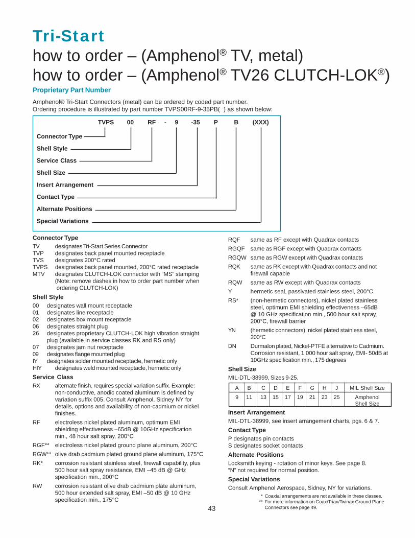
43
Tri-Starthow to order – (Amphenol® TV, metal)how to order – (Amphenol® TV26 CLUTCH-LOK®)
Connector TypeTV designates Tri-Start Series ConnectorTVP designates back panel mounted receptacleTVS designates 200°C ratedTVPS designates back panel mounted, 200°C rated receptacleMTV designates CLUTCH-LOK connector with “MS” stamping
(Note: remove dashes in how to order part number when ordering CLUTCH-LOK)
Shell Style00 designates wall mount receptacle01 designates line receptacle02 designates box mount receptacle06 designates straight plug26 designates proprietary CLUTCH-LOK high vibration straight
plug (available in service classes RK and RS only)07 designates jam nut receptacle09 designates flange mounted plugIY designates solder mounted receptacle, hermetic onlyHIY designates weld mounted receptacle, hermetic only
Service ClassRX alternate finish, requires special variation suffix. Example:
non-conductive, anodic coated aluminum is defined byvariation suffix 005. Consult Amphenol, Sidney NY fordetails, options and availability of non-cadmium or nickelfinishes.
RF electroless nickel plated aluminum, optimum EMIshielding effectiveness –65dB @ 10GHz specificationmin., 48 hour salt spray, 200°C
RGF** electroless nickel plated ground plane aluminum, 200°C
RGW** olive drab cadmium plated ground plane aluminum, 175°C
RK* corrosion resistant stainless steel, firewall capability, plus500 hour salt spray resistance, EMI –45 dB @ GHzspecification min., 200°C
RW corrosion resistant olive drab cadmium plate aluminum,500 hour extended salt spray, EMI –50 dB @ 10 GHzspecification min., 175°C
RQF same as RF except with Quadrax contacts
RGQF same as RGF except with Quadrax contacts
RGQW same as RGW except with Quadrax contacts
RQK same as RK except with Quadrax contacts and notfirewall capable
RQW same as RW except with Quadrax contacts
Y hermetic seal, passivated stainless steel, 200°C
RS* (non-hermetic connectors), nickel plated stainlesssteel, optimum EMI shielding effectiveness –65dB@ 10 GHz specification min., 500 hour salt spray,200°C, firewall barrier
YN (hermetic connectors), nickel plated stainless steel,200°C
DN Durmalon plated, Nickel-PTFE alternative to Cadmium.Corrosion resistant, 1,000 hour salt spray, EMI- 50dB at10GHz specification min., 175 degrees
Shell SizeMIL-DTL-38999, Sizes 9-25.
TVPS 00 RF - 9 -35 P B (XXX)
Connector Type
Shell Style
Service Class
Shell Size
Insert Arrangement
Contact Type
Alternate Positions
Special Variations
Proprietary Part Number
* Coaxial arrangements are not available in these classes.** For more information on Coax/Triax/Twinax Ground Plane
Connectors see page 49.
A B C D E F G H J MIL Shell Size
9 11 13 15 17 19 21 23 25 AmphenolShell Size
Insert ArrangementMIL-DTL-38999, see insert arrangement charts, pgs. 6 & 7.
Contact TypeP designates pin contactsS designates socket contacts
Alternate PositionsLocksmith keying - rotation of minor keys. See page 8.“N” not required for normal position.
Special VariationsConsult Amphenol Aerospace, Sidney, NY for variations.
Amphenol® Tri-Start Connectors (metal) can be ordered by coded part number.Ordering procedure is illustrated by part number TVPS00RF-9-35PB( ) as shown below:
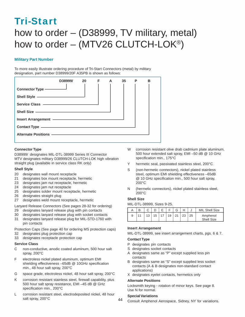
44
Tri-Starthow to order – (D38999, TV military, metal)how to order – (MTV26 CLUTCH-LOK®)
Connector TypeD38999/ designates MIL-DTL-38999 Series III ConnectorMTV designates military D38999/26 CLUTCH-LOK high vibrationstraight plug (available in service class RK only)
Shell Style20 designates wall mount receptacle21 designates box mount receptacle, hermetic23 designates jam nut receptacle, hermetic24 designates jam nut receptacle25 designates solder mount receptacle, hermetic26 designates straight plug27 designates weld mount receptacle, hermetic
Lanyard Release Connectors (See pages 28-32 for ordering)29 designates lanyard release plug with pin contacts30 designates lanyard release plug with socket contacts31 designates lanyard release plug for MIL-STD-1760 with
pin contacts
Protection Caps (See page 40 for ordering MS protection caps)32 designates plug protection cap33 designates receptacle protection cap
Service ClassC non-conductive, anodic coated aluminum, 500 hour salt
spray, 200°C
F electroless nickel plated aluminum, optimum EMIshielding effectiveness –65dB @ 10GHz specificationmin., 48 hour salt spray, 200°C
G space grade, electroless nickel, 48 hour salt spray, 200°C
K corrosion resistant stainless steel, firewall capability, plus500 hour salt spray resistance, EMI –45 dB @ GHzspecification min., 200°C
L corrosion resistant steel, electrodeposited nickel, 48 hoursalt spray, 200°C
W corrosion resistant olive drab cadmium plate aluminum,500 hour extended salt spray, EMI –50 dB @ 10 GHzspecification min., 175°C
Y hermetic seal, passivated stainless steel, 200°C
S (non-hermetic connectors), nickel plated stainlesssteel, optimum EMI shielding effectiveness –65dB@ 10 GHz specification min., 500 hour salt spray,200°C
N (hermetic connectors), nickel plated stainless steel,200°C
Shell SizeMIL-DTL-38999, Sizes 9-25.
D38999/ 20 F A 35 P B
Connector Type
Shell Style
Service Class
Shell Size
Insert Arrangement
Contact Type
Alternate Positions
Military Part Number
To more easily illustrate ordering procedure of Tri-Start Connectors (metal) by militarydesignation, part number D38999/20F A35PB is shown as follows:
A B C D E F G H J MIL Shell Size
9 11 13 15 17 19 21 23 25 AmphenolShell Size
Insert ArrangementMIL-DTL-38999, see insert arrangement charts, pgs. 6 & 7.
Contact TypeP designates pin contactsS designates socket contactsA designates same as “P” except supplied less pin
contactsB designates same as “S” except supplied less socket
contacts (A & B designates non-standard contactapplications)
X designates eyelet contacts, hermetics only
Alternate PositionsLocksmith keying - rotation of minor keys. See page 8.Use N for normal.
Special VariationsConsult Amphenol Aerospace, Sidney, NY for variations.
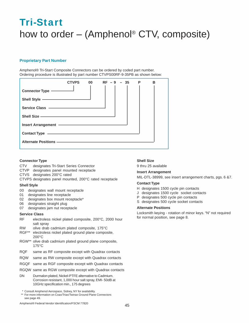
45
Connector TypeCTV designates Tri-Start Series ConnectorCTVP designates panel mounted receptacleCTVS designates 200°C ratedCTVPS designates panel mounted, 200°C rated receptacle
Shell Style00 designates wall mount receptacle01 designates line receptacle02 designates box mount receptacle*06 designates straight plug07 designates jam nut receptacle
Service ClassRF electroless nickel plated composite, 200°C, 2000 hour
salt sprayRW olive drab cadmium plated composite, 175°CRGF** electroless nickel plated ground plane composite,
200°CRGW** olive drab cadmium plated ground plane composite,
175°C
RQF same as RF composite except with Quadrax contacts
RQW same as RW composite except with Quadrax contacts
RGQF same as RGF composite except with Quadrax contacts
RGQW same as RGW composite except with Quadrax contacts
DN Durmalon plated, Nickel-PTFE alternative to Cadmium.Corrosion resistant, 1,000 hour salt spray, EMI- 50dB at10GHz specification min., 175 degrees
Shell Size9 thru 25 available
Insert ArrangementMIL-DTL-38999, see insert arrangement charts, pgs. 6 &7.
Contact TypeH designates 1500 cycle pin contactsJ designates 1500 cycle socket contactsP designates 500 cycle pin contactsS designates 500 cycle socket contacts
Alternate PositionsLocksmith keying - rotation of minor keys. “N” not requiredfor normal position, see page 8.
CTVPS 00 RF – 9 – 35 P B
Connector Type
Shell Style
Service Class
Shell Size
Insert Arrangement
Contact Type
Alternate Positions
Proprietary Part Number
* Consult Amphenol Aerospace, Sidney, NY for availability.** For more information on Coax/Triax/Twinax Ground Plane Connectors
see page 49.
Tri-Starthow to order – (Amphenol® CTV, composite)
Amphenol® Tri-Start Composite Connectors can be ordered by coded part number.Ordering procedure is illustrated by part number CTVPS00RF-9-35PB as shown below:
Amphenol® Federal Vendor Identification/FSCM 77820
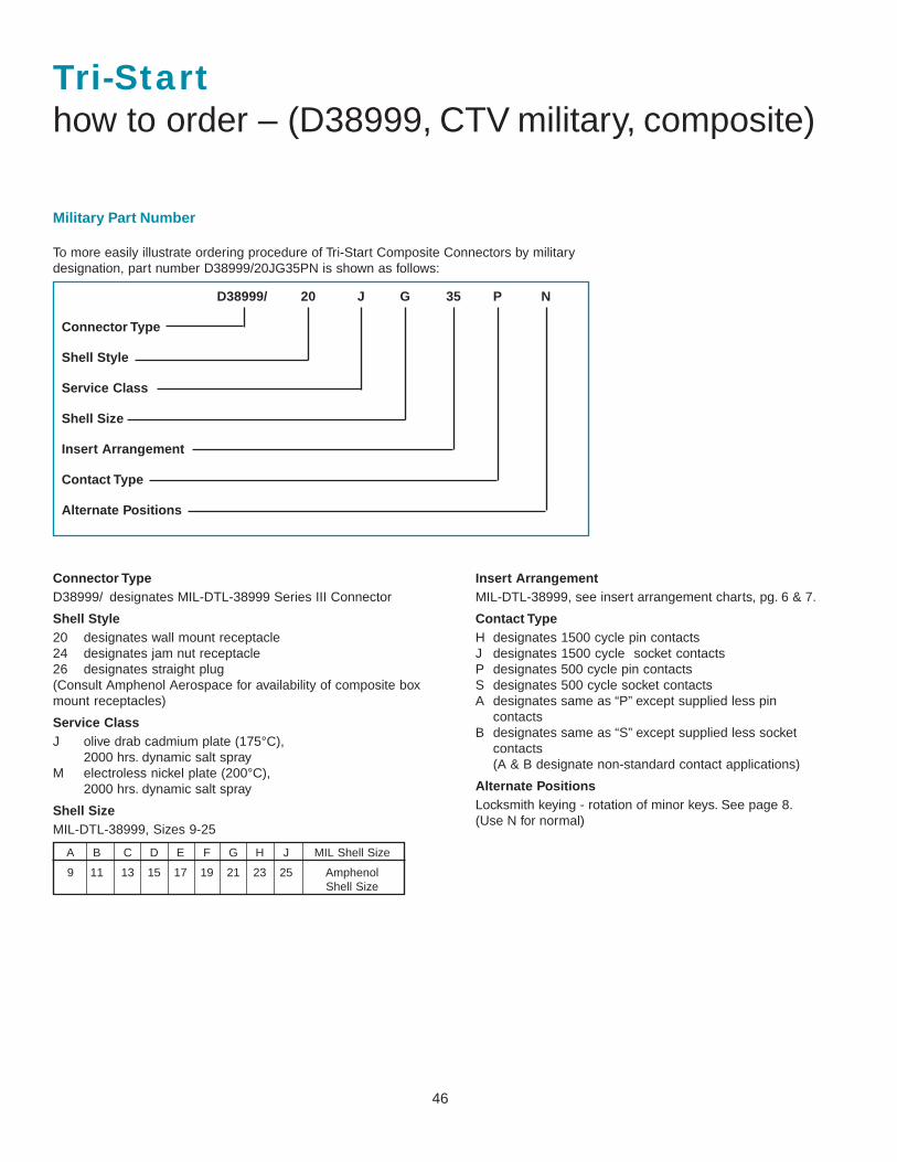
46
Connector TypeD38999/ designates MIL-DTL-38999 Series III Connector
Shell Style20 designates wall mount receptacle24 designates jam nut receptacle26 designates straight plug(Consult Amphenol Aerospace for availability of composite boxmount receptacles)
Service ClassJ olive drab cadmium plate (175°C),
2000 hrs. dynamic salt sprayM electroless nickel plate (200°C),
2000 hrs. dynamic salt spray
Shell SizeMIL-DTL-38999, Sizes 9-25
Insert ArrangementMIL-DTL-38999, see insert arrangement charts, pg. 6 & 7.
Contact TypeH designates 1500 cycle pin contactsJ designates 1500 cycle socket contactsP designates 500 cycle pin contactsS designates 500 cycle socket contactsA designates same as “P” except supplied less pin
contactsB designates same as “S” except supplied less socket
contacts(A & B designate non-standard contact applications)
Alternate PositionsLocksmith keying - rotation of minor keys. See page 8.(Use N for normal)
D38999/ 20 J G 35 P N
Connector Type
Shell Style
Service Class
Shell Size
Insert Arrangement
Contact Type
Alternate Positions
Military Part Number
To more easily illustrate ordering procedure of Tri-Start Composite Connectors by militarydesignation, part number D38999/20JG35PN is shown as follows:
Tri-Starthow to order – (D38999, CTV military, composite)
A B C D E F G H J MIL Shell Size
9 11 13 15 17 19 21 23 25 AmphenolShell Size
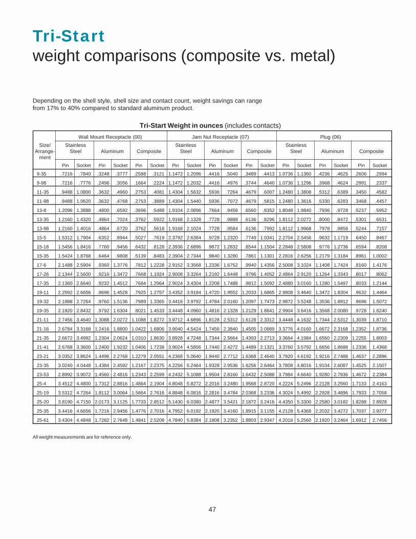
47
Tri-Startweight comparisons (composite vs. metal)
Wall Mount Receptacle (00) Jam Nut Receptacle (07) Plug (06)
Size/ Stainless Stainless StainlessArrange- Steel Aluminum Composite Steel Aluminum Composite Steel Aluminum Composite
ment
Pin Socket Pin Socket Pin Socket Pin Socket Pin Socket Pin Socket Pin Socket Pin Socket Pin Socket
9-35 .7216 .7840 .3248 .3777 .2588 .3121 1.1472 1.2096 .4416 .5040 .3489 .4413 1.0736 1.1360 .4236 .4625 .2606 .2994
9-98 .7216 .7776 .2496 .3056 .1664 .2224 1.1472 1.2032 .4416 .4976 .3744 .4640 1.0736 1.1296 .3968 .4624 .2991 .2337
11-35 .9488 1.0800 .3632 .4960 .2753 .4081 1.4304 1.5632 .5936 .7264 .4679 .6007 1.2480 1.3808 .5312 .6389 .3450 .4582
11-98 .9488 1.0620 .3632 .4768 .2753 .3889 1.4304 1.5440 .5936 .7072 .4679 .5815 1.2480 1.3616 .5330 .6283 .3468 .4457
13-8 1.2096 1.3888 .4800 .6592 .3696 .5488 1.9104 2.0896 .7664 .9456 .6560 .8352 1.8048 1.9840 .7936 .9728 .5237 .5952
13-35 1.2160 1.4320 .4864 .7024 .3762 .5922 1.9168 2.1328 .7728 .9888 .6136 .8296 1.8112 2.0272 .8000 .8472 .5301 .6531
13-98 1.2160 1.4016 .4864 .6720 .3762 .5618 1.9168 2.1024 .7728 .9584 .6136 .7992 1.8112 1.9968 .7978 .9856 .5244 .7157
15-5 1.5312 1.7904 .6352 .8944 .5027 .7619 2.3792 2.6384 .9728 1.2320 .7749 1.0341 2.2704 2.5456 .9632 1.1719 .6450 .8467
15-18 1.5456 1.8416 .7760 .9456 .6432 .8128 2.3936 2.6896 .9872 1.2832 .8544 1.1504 2.2848 2.5808 .9776 1.2736 .6594 .8208
15-35 1.5424 1.8768 .6464 .9808 .5139 .8483 2.3904 2.7344 .9840 1.3280 .7861 1.1301 2.2816 2.6256 1.2179 1.3184 .8961 1.0002
17-6 2.1488 2.5904 .9360 1.3776 .7812 1.2228 2.9152 3.3568 1.2336 1.6752 .9940 1.4356 2.5008 3.1024 1.1408 1.7424 .8160 1.4176
17-26 2.1344 2.5600 .9216 1.3472 .7668 1.1924 2.9008 3.3264 1.2192 1.6448 .9796 1.4052 2.4864 2.9120 1.1264 1.3343 .8017 .8062
17-35 2.1360 2.6640 .9232 1.4512 .7684 1.2964 2.9024 3.4304 1.2208 1.7488 .9812 1.5092 2.4880 3.0160 1.1280 1.5497 .8033 1.2144
19-11 2.2592 2.6656 .9696 1.4528 .7925 1.2757 3.4352 3.9184 1.4720 1.9552 1.2033 1.6865 2.9808 3.4640 1.3472 1.8304 .9632 1.4464
19-32 2.1888 2.7264 .9760 1.5136 .7989 1.3365 3.4416 3.9792 1.4784 2.0160 1.2097 1.7473 2.9872 3.5248 1.3536 1.8912 .9696 1.5072
19-35 2.1920 2.8432 .9792 1.6304 .8021 1.4533 3.4448 4.0960 1.4816 2.1328 1.2129 1.8641 2.9904 3.6416 1.3568 2.0080 .9728 1.6240
21-11 2.7456 3.4640 1.3088 2.0272 1.1088 1.8272 3.9712 4.6896 1.8128 2.5312 1.6128 2.3312 3.4448 4.1632 1.7344 2.5312 1.3039 1.8710
21-16 2.6784 3.3168 1.2416 1.8800 1.0422 1.6806 3.9040 4.5424 1.7456 2.3840 1.4505 2.0889 3.3776 4.0160 1.6672 2.3168 1.2352 1.8736
21-35 2.6672 3.4992 1.2304 2.0624 1.0310 1.8630 3.8928 4.7248 1.7344 2.5664 1.4393 2.2713 3.3664 4.1984 1.6560 2.2309 1.2255 1.8003
21-41 2.6768 3.3600 1.2400 1.9232 1.0406 1.7238 3.9024 4.5856 1.7440 2.4272 1.4489 2.1321 3.3760 3.5792 1.6656 1.8688 1.2336 1.4368
23-21 3.0352 3.8624 1.4496 2.2768 1.2279 2.0551 4.2368 5.0640 1.9440 2.7712 1.6368 2.4640 3.7920 4.6192 1.9216 2.7488 1.4637 2.2896
23-35 3.0240 4.0448 1.4384 2.4592 1.2167 2.2375 4.2256 5.2464 1.9328 2.9536 1.6256 2.6464 3.7808 4.8016 1.9104 2.6087 1.4525 2.1507
23-53 2.8992 3.9072 1.4560 2.4816 1.2343 2.2599 4.2432 5.1088 1.9504 2.8160 1.6432 2.5088 3.7984 4.6640 1.9280 2.7936 1.4672 2.2384
25-4 3.4512 4.4800 1.7312 2.8816 1.4864 2.1904 4.8048 5.8272 2.2016 3.2480 1.9568 2.8720 4.2224 5.2496 2.2128 3.2560 1.7133 2.4163
25-19 3.5312 4.7264 1.8112 3.0064 1.5664 2.7616 4.8848 6.0816 2.2816 3.4784 2.0368 3.2336 4.3024 5.4992 2.2928 3.4896 1.7933 2.7058
25-20 3.8190 4.7150 2.0173 3.1125 1.7733 2.8512 5.1430 6.0380 2.4877 3.5421 2.1872 3.2416 4.4350 5.3300 2.2580 3.0182 1.8288 2.8928
25-35 3.4416 4.6656 1.7216 2.9456 1.4776 2.7016 4.7952 6.0192 2.1920 3.4160 1.8915 3.1155 4.2128 5.4368 2.2032 3.4272 1.7037 2.9277
25-61 3.4304 4.4848 1.7282 2.7648 1.4841 2.5208 4.7840 5.8384 2.1808 3.2352 1.8803 2.9347 4.2016 5.2560 2.1920 3.2464 1.6912 2.7456
Tri-Start Weight in ounces (includes contacts)
All weight measurements are for reference only.
Depending on the shell style, shell size and contact count, weight savings can rangefrom 17% to 40% compared to standard aluminum product.
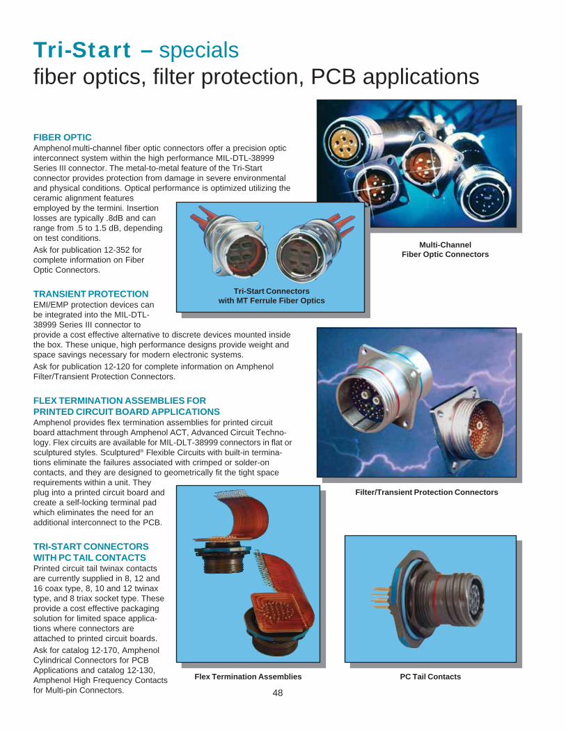
48
Tri-Start – specialsfiber optics, filter protection, PCB applications
FIBER OPTICAmphenol
multi-channel fiber optic connectors offer a precision optic
interconnect system within the high performance MIL-DTL-38999Series III connector. The metal-to-metal feature of the Tri-Startconnector provides protection from damage in severe environmentaland physical conditions. Optical performance is optimized utilizing theceramic alignment featuresemployed by the termini. Insertionlosses are typically .8dB and canrange from .5 to 1.5 dB, dependingon test conditions.Ask for publication 12-352 forcomplete information on FiberOptic Connectors.
TRANSIENT PROTECTIONEMI/EMP protection devices canbe integrated into the MIL-DTL-38999 Series III connector toprovide a cost effective alternative to discrete devices mounted insidethe box. These unique, high performance designs provide weight andspace savings necessary for modern electronic systems.Ask for publication 12-120 for complete information on AmphenolFilter/Transient Protection Connectors.
FLEX TERMINATION ASSEMBLIES FORPRINTED CIRCUIT BOARD APPLICATIONSAmphenol provides flex termination assemblies for printed circuitboard attachment through Amphenol ACT, Advanced Circuit Techno-logy. Flex circuits are available for MIL-DLT-38999 connectors in flat orsculptured styles. Sculptured® Flexible Circuits with built-in termina-tions eliminate the failures associated with crimped or solder-oncontacts, and they are designed to geometrically fit the tight spacerequirements within a unit. Theyplug into a printed circuit board andcreate a self-locking terminal padwhich eliminates the need for anadditional interconnect to the PCB.
TRI-START CONNECTORSWITH PC TAIL CONTACTSPrinted circuit tail twinax contactsare currently supplied in 8, 12 and16 coax type, 8, 10 and 12 twinaxtype, and 8 triax socket type. Theseprovide a cost effective packagingsolution for limited space applica-tions where connectors areattached to printed circuit boards.Ask for catalog 12-170, AmphenolCylindrical Connectors for PCBApplications and catalog 12-130,Amphenol High Frequency Contactsfor Multi-pin Connectors.
Multi-ChannelFiber Optic Connectors
Filter/Transient Protection Connectors
Flex Termination Assemblies
Tri-Start Connectorswith MT Ferrule Fiber Optics
PC Tail Contacts
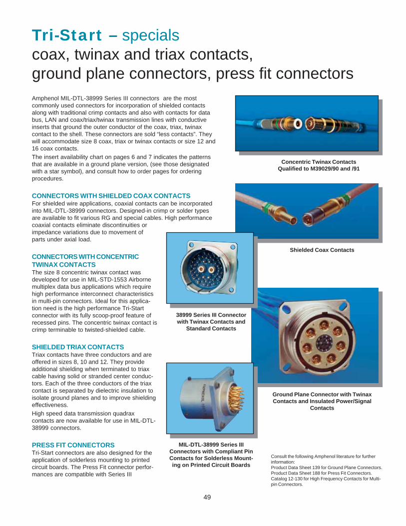
49
Tri-Start – specialscoax, twinax and triax contacts,ground plane connectors, press fit connectorsAmphenol MIL-DTL-38999 Series III connectors are the mostcommonly used connectors for incorporation of shielded contactsalong with traditional crimp contacts and also with contacts for databus, LAN and coax/triax/twinax transmission lines with conductiveinserts that ground the outer conductor of the coax, triax, twinaxcontact to the shell. These connectors are sold “less contacts”. Theywill accommodate size 8 coax, triax or twinax contacts or size 12 and16 coax contacts.The insert availability chart on pages 6 and 7 indicates the patternsthat are available in a ground plane version, (see those designatedwith a star symbol), and consult how to order pages for orderingprocedures.
CONNECTORS WITH SHIELDED COAX CONTACTSFor shielded wire applications, coaxial contacts can be incorporatedinto MIL-DTL-38999 connectors. Designed-in crimp or solder typesare available to fit various RG and special cables. High performancecoaxial contacts eliminate discontinuities orimpedance variations due to movement ofparts under axial load.
Concentric Twinax ContactsQualified to M39029/90 and /91
CONNECTORS WITH CONCENTRICTWINAX CONTACTSThe size 8 concentric twinax contact wasdeveloped for use in MIL-STD-1553 Airbornemultiplex data bus applications which requirehigh performance interconnect characteristicsin multi-pin connectors. Ideal for this applica-tion need is the high performance Tri-Startconnector with its fully scoop-proof feature ofrecessed pins. The concentric twinax contact iscrimp terminable to twisted-shielded cable.
SHIELDED TRIAX CONTACTSTriax contacts have three conductors and areoffered in sizes 8, 10 and 12. They provideadditional shielding when terminated to triaxcable having solid or stranded center conduc-tors. Each of the three conductors of the triaxcontact is separated by dielectric insulation toisolate ground planes and to improve shieldingeffectiveness.High speed data transmission quadraxcontacts are now available for use in MIL-DTL-38999 connectors.
PRESS FIT CONNECTORSTri-Start connectors are also designed for theapplication of solderless mounting to printedcircuit boards. The Press Fit connector perfor-mances are compatible with Series III
Ground Plane Connector with TwinaxContacts and Insulated Power/Signal
Contacts
MIL-DTL-38999 Series IIIConnectors with Compliant PinContacts for Solderless Mount-ing on Printed Circuit Boards
Consult the following Amphenol literature for furtherinformation:Product Data Sheet 139 for Ground Plane Connectors.Product Data Sheet 188 for Press Fit Connectors.Catalog 12-130 for High Frequency Contacts for Multi-pin Connectors.
38999 Series III Connectorwith Twinax Contacts and
Standard Contacts
Shielded Coax Contacts
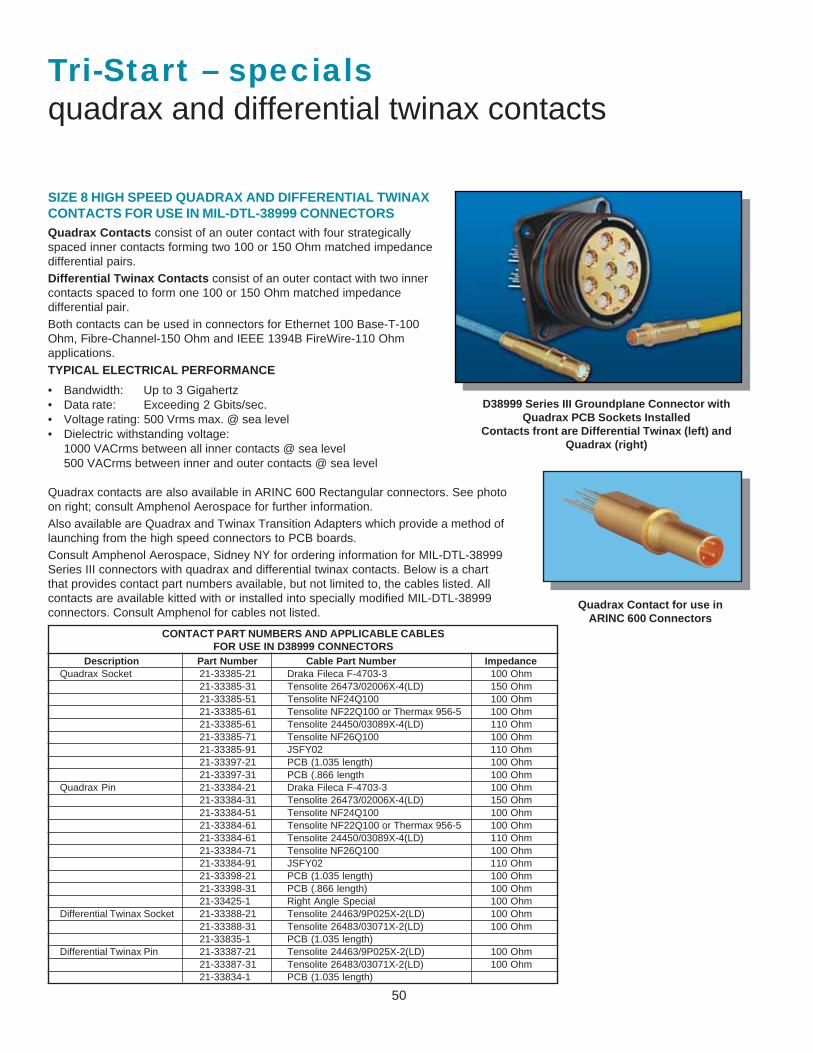
50
Tri-Start – specialsquadrax and differential twinax contacts
SIZE 8 HIGH SPEED QUADRAX AND DIFFERENTIAL TWINAXCONTACTS FOR USE IN MIL-DTL-38999 CONNECTORSQuadrax Contacts consist of an outer contact with four strategicallyspaced inner contacts forming two 100 or 150 Ohm matched impedancedifferential pairs.Differential Twinax Contacts consist of an outer contact with two innercontacts spaced to form one 100 or 150 Ohm matched impedancedifferential pair.Both contacts can be used in connectors for Ethernet 100 Base-T-100Ohm, Fibre-Channel-150 Ohm and IEEE 1394B FireWire-110 Ohmapplications.TYPICAL ELECTRICAL PERFORMANCE
• Bandwidth: Up to 3 Gigahertz• Data rate: Exceeding 2 Gbits/sec.• Voltage rating: 500 Vrms max. @ sea level• Dielectric withstanding voltage:
1000 VACrms between all inner contacts @ sea level500 VACrms between inner and outer contacts @ sea level
Quadrax contacts are also available in ARINC 600 Rectangular connectors. See photoon right; consult Amphenol Aerospace for further information.Also available are Quadrax and Twinax Transition Adapters which provide a method oflaunching from the high speed connectors to PCB boards.Consult Amphenol Aerospace, Sidney NY for ordering information for MIL-DTL-38999Series III connectors with quadrax and differential twinax contacts. Below is a chartthat provides contact part numbers available, but not limited to, the cables listed. Allcontacts are available kitted with or installed into specially modified MIL-DTL-38999connectors. Consult Amphenol for cables not listed.
D38999 Series III Groundplane Connector withQuadrax PCB Sockets Installed
Contacts front are Differential Twinax (left) andQuadrax (right)
CONTACT PART NUMBERS AND APPLICABLE CABLESFOR USE IN D38999 CONNECTORS
Description Part Number Cable Part Number ImpedanceQuadrax Socket 21-33385-21 Draka Fileca F-4703-3 100 Ohm
21-33385-31 Tensolite 26473/02006X-4(LD) 150 Ohm21-33385-51 Tensolite NF24Q100 100 Ohm21-33385-61 Tensolite NF22Q100 or Thermax 956-5 100 Ohm21-33385-61 Tensolite 24450/03089X-4(LD) 110 Ohm21-33385-71 Tensolite NF26Q100 100 Ohm21-33385-91 JSFY02 110 Ohm21-33397-21 PCB (1.035 length) 100 Ohm21-33397-31 PCB (.866 length 100 Ohm
Quadrax Pin 21-33384-21 Draka Fileca F-4703-3 100 Ohm21-33384-31 Tensolite 26473/02006X-4(LD) 150 Ohm21-33384-51 Tensolite NF24Q100 100 Ohm21-33384-61 Tensolite NF22Q100 or Thermax 956-5 100 Ohm21-33384-61 Tensolite 24450/03089X-4(LD) 110 Ohm21-33384-71 Tensolite NF26Q100 100 Ohm21-33384-91 JSFY02 110 Ohm21-33398-21 PCB (1.035 length) 100 Ohm21-33398-31 PCB (.866 length) 100 Ohm21-33425-1 Right Angle Special 100 Ohm
Differential Twinax Socket 21-33388-21 Tensolite 24463/9P025X-2(LD) 100 Ohm21-33388-31 Tensolite 26483/03071X-2(LD) 100 Ohm21-33835-1 PCB (1.035 length)
Differential Twinax Pin 21-33387-21 Tensolite 24463/9P025X-2(LD) 100 Ohm21-33387-31 Tensolite 26483/03071X-2(LD) 100 Ohm21-33834-1 PCB (1.035 length)
Quadrax Contact for use inARINC 600 Connectors
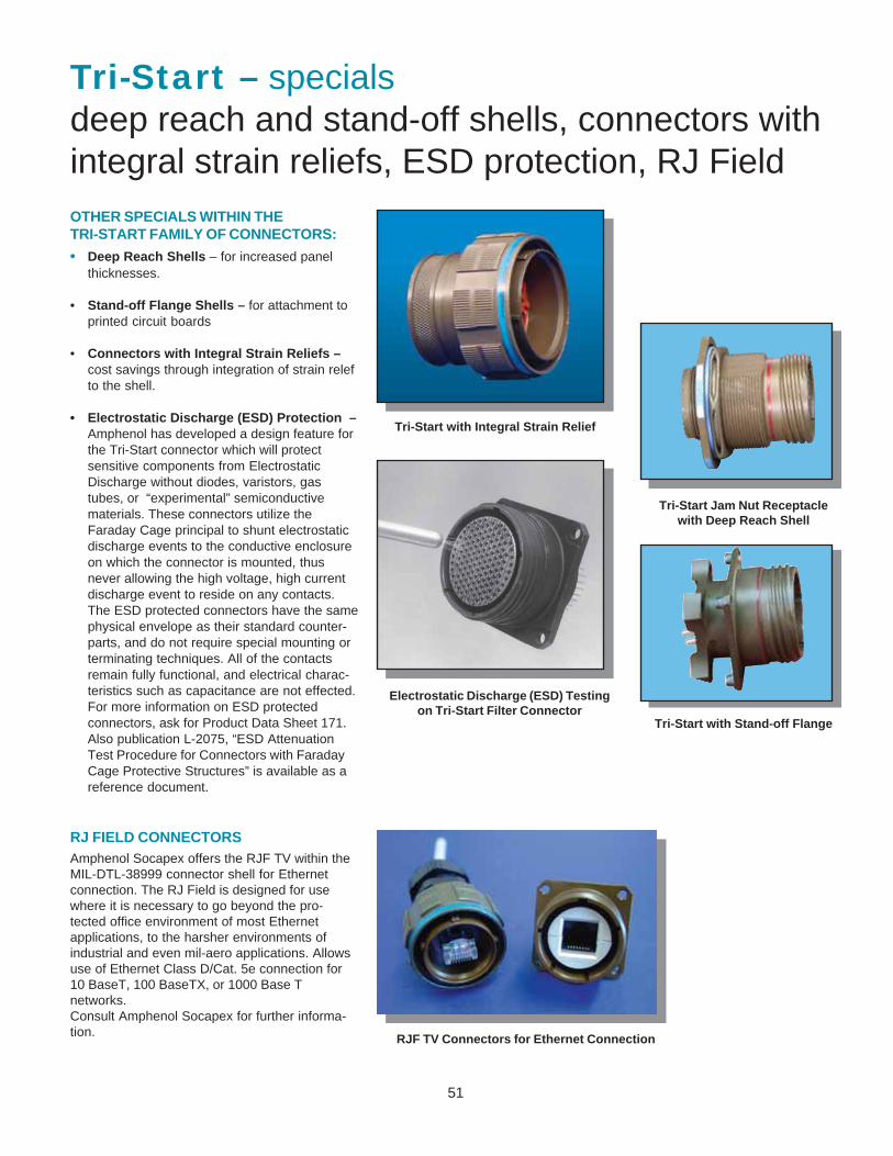
51
Tri-Start – specialsdeep reach and stand-off shells, connectors withintegral strain reliefs, ESD protection, RJ FieldOTHER SPECIALS WITHIN THETRI-START FAMILY OF CONNECTORS:
• Deep Reach Shells – for increased panelthicknesses.
• Stand-off Flange Shells – for attachment toprinted circuit boards
• Connectors with Integral Strain Reliefs –cost savings through integration of strain relefto the shell.
• Electrostatic Discharge (ESD) Protection –Amphenol has developed a design feature forthe Tri-Start connector which will protectsensitive components from ElectrostaticDischarge without diodes, varistors, gastubes, or “experimental” semiconductivematerials. These connectors utilize theFaraday Cage principal to shunt electrostaticdischarge events to the conductive enclosureon which the connector is mounted, thusnever allowing the high voltage, high currentdischarge event to reside on any contacts.The ESD protected connectors have the samephysical envelope as their standard counter-parts, and do not require special mounting orterminating techniques. All of the contactsremain fully functional, and electrical charac-teristics such as capacitance are not effected.For more information on ESD protectedconnectors, ask for Product Data Sheet 171.Also publication L-2075, “ESD AttenuationTest Procedure for Connectors with FaradayCage Protective Structures” is available as areference document.
Tri-Start Jam Nut Receptaclewith Deep Reach Shell
Tri-Start with Stand-off Flange
Tri-Start with Integral Strain Relief
Electrostatic Discharge (ESD) Testingon Tri-Start Filter Connector
RJ FIELD CONNECTORSAmphenol Socapex offers the RJF TV within theMIL-DTL-38999 connector shell for Ethernetconnection. The RJ Field is designed for usewhere it is necessary to go beyond the pro-tected office environment of most Ethernetapplications, to the harsher environments ofindustrial and even mil-aero applications. Allowsuse of Ethernet Class D/Cat. 5e connection for10 BaseT, 100 BaseTX, or 1000 Base Tnetworks.Consult Amphenol Socapex for further informa-tion. RJF TV Connectors for Ethernet Connection
52
Amphenol CorporationAmphenol AerospaceAmphenol Industrial Operations40-60 Delaware AvenueSidney, NY 13838-1395Phone: 607-563-5011 1-800-678-0141Fax: 607-563-5157www.amphenol-aerospace.comwww.amphenol-industrial.com
SALES OFFICESAmphenol CorporationAmphenol Aerospace23276 South Pointe DriveSuite 113Laguna Hills, CA 92653Phone: 949-855-4454 1-800-678-0141Fax: 949-855-9115
Amphenol CorporationAmphenol Aerospace2010 Corporate RidgeMcLean, VA 22101Phone: 1-800-678-0141
Amphenol Pcd2 Technology DrivePeabody, MA 01960Phone: 978-532-8800Fax: 978-532-6800Web: www.amphenolpcd.com
Amphenol Backplane Systems18 Celina AvenueNashua, NH 03063Phone: 888-318-3553Fax: 603-883-0247www.amphenol.abs.com
Amphenol Advance CircuitTechnology118 Northeastern BoulevardNashua, NH 03062Phone: 603-880-6000Fax: 603-880-1785Web: www.act.flexcircuit.com
Amphenol Canada20 Melford DriveScarborough, ON M1B 2X6 CanadaPhone: 416-291-4401Fax: 416-292-0647Web: www.amphenolcanada.com
DISTRIBUTORSCorporate HeadquartersARROW ELECTRONICS7459 S. Lima StreetEnglewood, CO 80112-5816Phone: 800-777-2776Fax: 800-562-3542Web: www.arrow.com
AVNET2211 47th StreetPhoenix, AZ 85034Phone: 800-332-8638Web: www.avnet.com
PEI GENESIS2180 Hornig RoadPhiladelphia, PA 19116Phone: 800-523-0727Fax: 215-552-8022Web: www.peigenesis.com
POWELL ELECTRONICS200 Commodore DriveLogan Township, NJ 08085Phone: 800-235-7880Fax: 215-937-4655Web: www.powell.com
TTI INC.2441 Northeast Pkwy.Fort Worth, TX 76106Phone: 800-225-5884Fax: 817-740-9494Web: www.ttiinc.com
SMALL DISADVANTAGED/MINORITY DISTRIBUTORSCHEROKEE NATION DISTRIBUTORSHighway 51 WestP.O. Box 1130Stilwell, OK 74960Phone: 918-696-2777Fax: 918-696-3129Web: www.cnicnd.com
JRH ELECTRONICS INC.2002 E. Lincoln Drive WestRoute 73, P.O. Box 264Marlton, NJ 08053Phone: 800-467-9309Fax: 609-988-8728Web: www.jrhelec.com
INTERNATIONALLatin AmericaARGENTINAAmphenol ArgentinaAvenida Callao 9302nd floor Office B PlazaC1023AAP Buenos Aires, ArgentinaPhone: (54 11) 48 15 68 86Fax: (54 11) 48 14 57 79E-mail:[email protected]
BRAZILAmphenol do Brasil Ltda.Rua Diogo Moreira 132CEP 05423-010Sao Paulo - SP, BrazilPhone: (55-11) 3815.1003Fax: (55-11) 3815.1629E-mail: [email protected]
MEXICOAmphenol MexicoProlongacion Reforma 61-6 B2Col. Paseo de las LomasC.P. 01330 Mexico D.F., MexicoPhone: (52-55) 5258.9984Fax: (52-55) 5081.6890E-mail: [email protected]
EuropeENGLANDAmphenol LimitedThanet Way, WhitstableKent CT5 3JF, United KingdomPhone: (44-1-227) 773200Fax: (44-1-227) 276571E-mail: [email protected]
FRANCEAmphenol SocapexPromenade de l’Arve, BP29Thyez 74311 948 Cedex, FrancePhone: (33-4) 50892800Fax: (33-4) 50961941Web: www.amphenol-socapex.com
GERMANYAmphenol-Tuchel Elect. GmbHAugust-Haeusser Strasse 10Postfach 111074001 Heilbronn, GermanyPhone: (49-7131) 929 0Fax: (49-7131) 929 414
GERMANYAmphenol-Air LB GmbHAm Kleinbahnhof 4D-66740 Saarlouis, GermanyPhone: (49-6831) 9810-87Fax: (49-6831) 9810-30Web: www.amphenol-airlb.com
ITALY & REST OF EUROPEAmphenol Italia S.p.A.Via Barbaiana 520020 Lainate (Milano), ItalyPhone: 39-02-932541Fax: 39-02-93254444E-mail: [email protected]
Middle East / AfricaISRAELBar-Tec Ltd.3 Hagavish St., P.O.B. 279Kfir-Barkan Bldg., East Industrial ZoneKfar Sava 44102, IsraelPhone: (972-9) 764.4100Fax: (972-9) 7674324E-mail: www.bar-tec.com
SOUTH AFRICAAmphenol South Africa30 Impala RoadChislehurstonSandton, 2146, South AfricaTel: (27-11) 783-9517Fax: (27-11) 783-9519E-mail: [email protected]
TURKEYAmphenol TurkiyeAyazaga Mah. Meydan Sk. No. 28Beybi Giz Plaza, Kat. 26 Maslak34396 IstanabulPhone: 90 (212) 335 25 01Fax: 990 (212) 335 25 00
Asia / PacificAUSTRALIAAmphenol Australia LTD2 Fiveways Blvd.Melbourne, Victoria 3173AustraliaPhone: 613 8796 8888Fax: 613 8796 8801E-mail: [email protected]
RUSSIAAmphenol Russia Office8-2 Yaroslavskaja Str.129164 Moscow, RussiaPhone: 7495 937 634E-mail: [email protected]
CHINAAmphenol Aerospace China OfficePhone: +607-563-4060E-mail: [email protected]
INDIAAmphenol Interconnect India Pvt,Ltd.105 Bhosari Industrial AreaPune, 411 026, IndiaPhone: (91-20) 27120 481Fax: (91-20) 27120 581E-mail: [email protected]
JAPANAmphenol Japan Mil/Aero &Industrial471-1, Debra, Ritto-cityShiga 520-3041, JapanPhone: 81-77-553-8501Fax: 81-77-551-2200
KOREAAmphenol Aerospace Korea OfficePhone: +607-563-4061E-mail: [email protected]
SOUTHEAST ASIAAmphenol Aerospace South EastAsia OfficePhone: +607-563-4062E-mail:[email protected]
TAIWANAmphenol Aerospace Taiwan OfficePhone: +607-563-4063E-mail: [email protected]
Notice: Specifications are subject to change without notice. Contact your nearest Amphenol Corporation Sales Office for the latest specifications. All statements, information and data given hereinare believed to be accurate and reliable but are presented without guarantee, warranty, or responsibility of any kind expressed or implied. Statements or suggestions concerning possible use of ourproducts are made without representation or warranty that any such use is free of patent infringement and are not recommendations to infringe any patent. The user should not assume that all safetymeasures are indicated or that other measures may not be required. Specifications are typical and may not apply to all connectors.
© 2006 Amphenol Corp. Printed in U.S.A. JCP 8/2006