Midterm Results 1. 2 Note 5: Peer-to-Peer Protocols and Data Link Control Flow Control.
61
Midterm Results 1
-
Upload
susanna-hodges -
Category
Documents
-
view
223 -
download
0
Transcript of Midterm Results 1. 2 Note 5: Peer-to-Peer Protocols and Data Link Control Flow Control.

Midterm Results
1
2
Note 5: Peer-to-Peer Protocols and Data Link Control
Flow Control
3
Flow Control
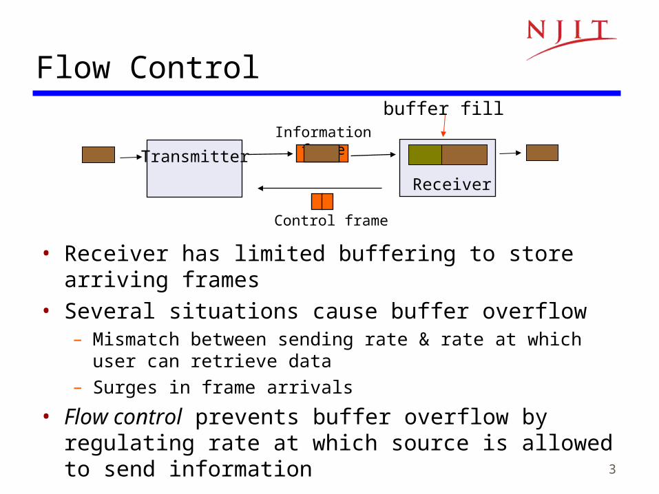
• Receiver has limited buffering to store arriving frames• Several situations cause buffer overflow
– Mismatch between sending rate & rate at which user can retrieve data
– Surges in frame arrivals
• Flow control prevents buffer overflow by regulating rate at which source is allowed to send information
Information frame
Control frame
Transmitter
Receiver
buffer fill
4
on off offon
A
B
2Tprop
Time
Time
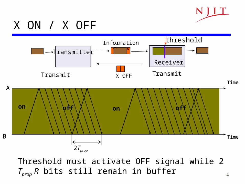
X ON / X OFF
Transmit Transmit
Information frame
X OFF
Transmitter
Receiver
threshold
Threshold must activate OFF signal while 2 Tprop R bits still remain in buffer
5
A
B
tcycle
Return of permits
Time
Time
Window Flow Control
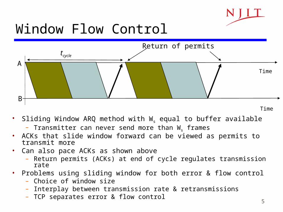
• Sliding Window ARQ method with Ws equal to buffer available– Transmitter can never send more than Ws frames
• ACKs that slide window forward can be viewed as permits to transmit more• Can also pace ACKs as shown above
– Return permits (ACKs) at end of cycle regulates transmission rate• Problems using sliding window for both error & flow control
– Choice of window size– Interplay between transmission rate & retransmissions– TCP separates error & flow control

6
Note 5: Peer-to-Peer Protocols and Data Link Control
Time Recovery

7
Network
Synchronous source sends periodic information blocks
Network output not periodic
Timing Recovery for Synchronous Services
• Applications that involve voice, audio, or video can generate a synchronous information stream
• Information carried by equally-spaced fixed-length packets • Network multiplexing & switching introduces random delays
– Packets experience variable transfer delay– Jitter (variation in interpacket arrival times) also introduced
• Timing recovery re-establishes the synchronous nature of the stream

8
Introduce Playout Buffer
PlayoutBuffer
Packet Arrivals Packet Playout
• Delay first packet by maximum network delay• All other packets arrive with less delay• Playout packet uniformly thereafter
Packet Arrivals
Packet Playout
Tmax
Sequence numbers help order packets
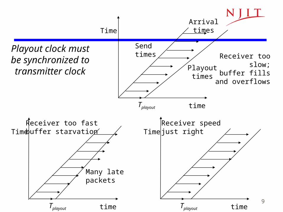
9
Sendtimes
Playouttimes
Arrival times
Tplayout time
Time
Receiver too slow;
buffer fills and overflows
Tplayout time
TimeReceiver too fastbuffer starvation
Many latepackets
Tplayout time
TimeReceiver speedjust right
Playout clock must be synchronized to transmitter clock
10
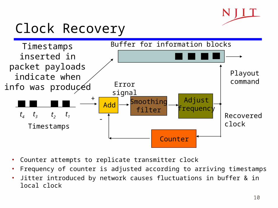
Recoveredclock
t4 t3 t2 t1
Timestamps
Add Smoothingfilter
Adjustfrequency
Counter
+
-
Buffer for information blocks
Errorsignal
Playoutcommand
Clock Recovery
• Counter attempts to replicate transmitter clock• Frequency of counter is adjusted according to arriving timestamps• Jitter introduced by network causes fluctuations in buffer & in local clock
Timestamps inserted in packet payloads
indicate when info was produced
11
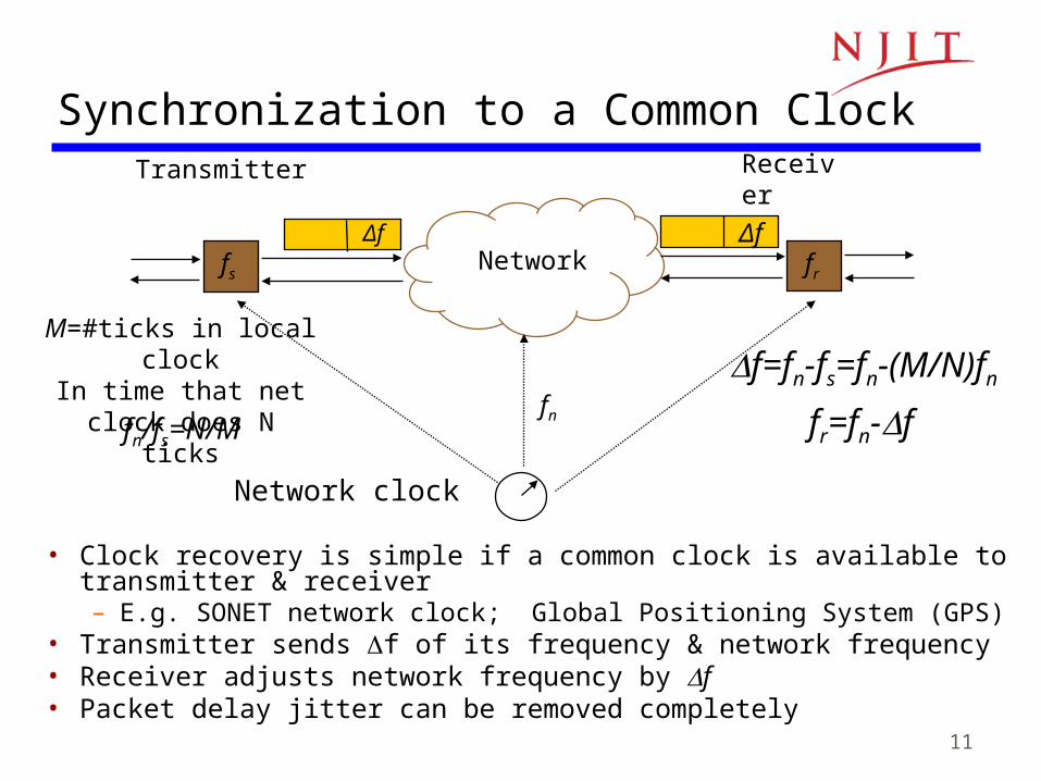
Network clock
fn
Transmitter
Network
Receiver
fs fr
Δf Δf
Synchronization to a Common Clock
• Clock recovery is simple if a common clock is available to transmitter & receiver– E.g. SONET network clock; Global Positioning System (GPS)
• Transmitter sends f of its frequency & network frequency• Receiver adjusts network frequency by f• Packet delay jitter can be removed completely
fr=fn-f
M=#ticks in local clockIn time that net clock
does N ticks
fn/fs=N/M
f=fn-fs=fn-(M/N)fn
12
Example: Real-Time Protocol
• RTP (RFC 1889) designed to support real-time applications such as voice, audio, video
• RTP provides means to carry:– Type of information source– Sequence numbers– Timestamps
• Actual timing recovery must be done by higher layer protocol– MPEG2 for video, MP3 for audio

13
Note 5: Peer-to-Peer Protocols and Data Link Control
Data Link Control Protocols

14
Data Link Protocols
• Directly connected, wire-like• Losses & errors, but no out-of-
sequence frames• Applications: Direct Links;
LANs; Connections across WANs
Data Links Services• Framing• Error control• Flow control• Multiplexing• Link Maintenance• Security: Authentication &
Encryption
Examples• PPP• HDLC• Ethernet LAN• IEEE 802.11 (Wi Fi) LAN
Data linklayer
Physicallayer
Physicallayer
Data linklayer
A B
Packets Packets
Frames
15
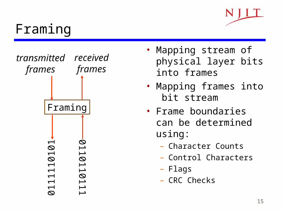
Framing• Mapping stream of
physical layer bits into frames
• Mapping frames into bit stream
• Frame boundaries can be determined using:– Character Counts– Control Characters– Flags– CRC Checks
0110110111
Framing
receivedframes
0111
1101
01transmitted
frames

16
Data to be sent
A DLE B ETX DLE STX E
After stuffing and framing
DLE DLE B ETX DLE DLE STXDLE STX A E DLE ETX
Character-Oriented Framing
• Frames consist of integer number of bytes– Asynchronous transmission systems using ASCII to transmit printable characters– Octets with HEX value <20 are nonprintable
• Special 8-bit patterns used as control characters– STX (start of text) = 0x02; ETX (end of text) = 0x03;
• Byte used to carry non-printable characters in frame– DLE (data link escape) = 0x10
– DLE STX (DLE ETX) used to indicate beginning (end) of frame – Insert extra DLE in front of occurrence of DLE in frame– All DLEs occur in pairs except at frame boundaries

17
Framing & Bit Stuffing
• Frame delineated by flag character• HDLC uses bit stuffing to prevent occurrence of flag
01111110 inside the frame • Transmitter inserts extra 0 after each consecutive five 1s
inside the frame• Receiver checks for five consecutive 1s
– if next bit = 0, it is removed– if next two bits are 10, then flag is detected– If next two bits are 11, then frame has errors
Flag FlagAddress Control Information FCS
HDLC frame
any number of bits

18
0110111111111100
Data to be sent
After stuffing and framing
0111111001101111101111100001111110
(a)
*000111011111-11111-110*
Data received
After destuffing and deframing
01111110000111011111011111011001111110
(b)
Example: Bit stuffing & de-stuffing
19
PPP Frame
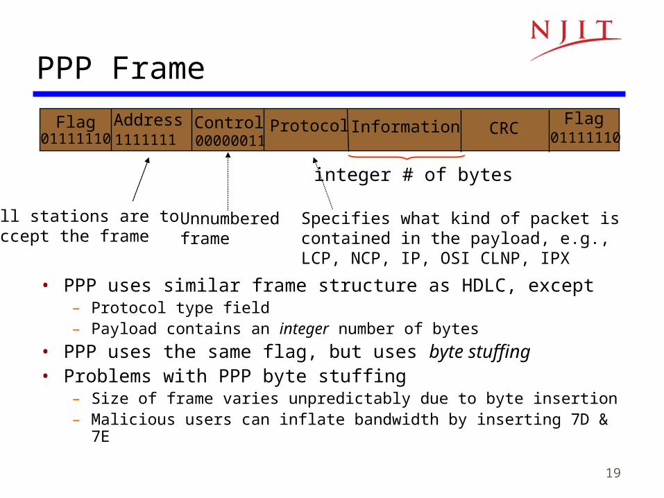
• PPP uses similar frame structure as HDLC, except– Protocol type field– Payload contains an integer number of bytes
• PPP uses the same flag, but uses byte stuffing• Problems with PPP byte stuffing
– Size of frame varies unpredictably due to byte insertion– Malicious users can inflate bandwidth by inserting 7D & 7E
Flag FlagAddress Control Information CRCProtocol01111110 011111101111111 00000011
Unnumbered frame
Specifies what kind of packet is contained in the payload, e.g., LCP, NCP, IP, OSI CLNP, IPX
All stations are toaccept the frame
integer # of bytes
20
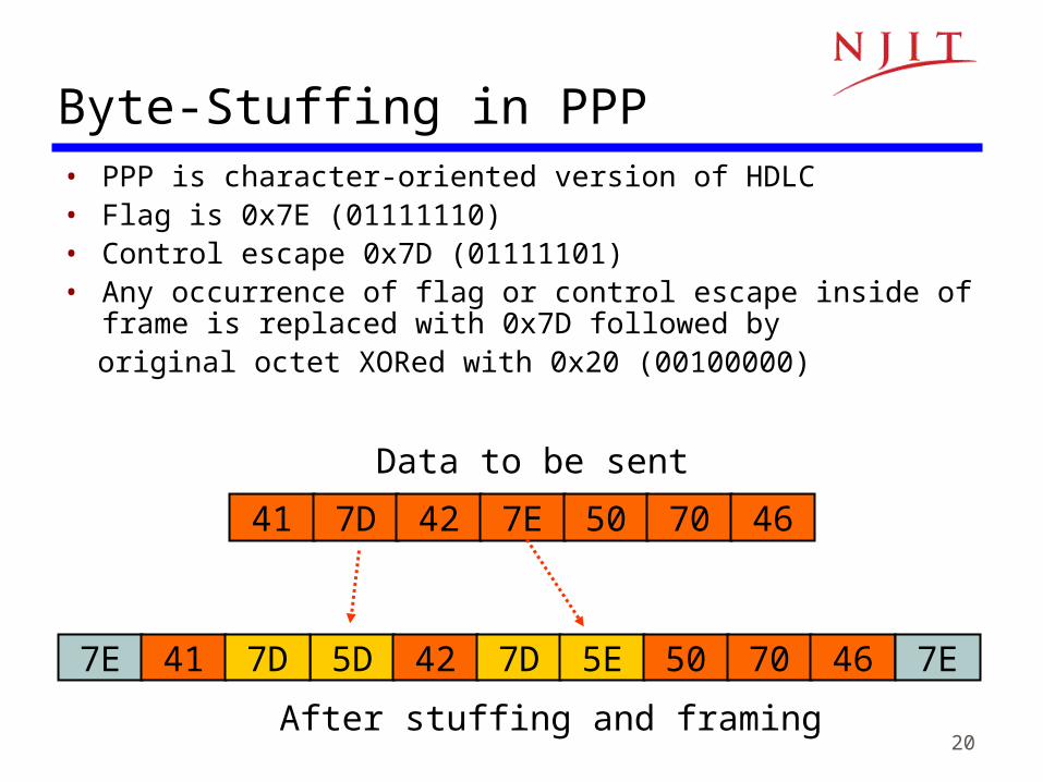
• PPP is character-oriented version of HDLC• Flag is 0x7E (01111110)• Control escape 0x7D (01111101)• Any occurrence of flag or control escape inside of frame is replaced
with 0x7D followed by original octet XORed with 0x20 (00100000)
Byte-Stuffing in PPP
Data to be sent
41 7D 42 7E 50 70 46
After stuffing and framing
5D 42 7D 5E 50 70 467E 41 7D 7E
21
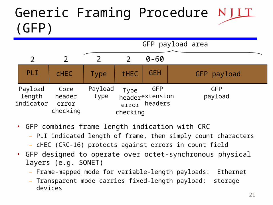
PLI cHEC Type GEH GFP payloadtHEC
Payloadtype
Payloadlength
indicator
Coreheadererror
checking
Typeheadererror
checking
GFPextensionheaders
GFPpayload
2 2 2 2 0-60
GFP payload area
Generic Framing Procedure (GFP)
• GFP combines frame length indication with CRC– PLI indicated length of frame, then simply count characters
– cHEC (CRC-16) protects against errors in count field
• GFP designed to operate over octet-synchronous physical layers (e.g. SONET)– Frame-mapped mode for variable-length payloads: Ethernet
– Transparent mode carries fixed-length payload: storage devices
22
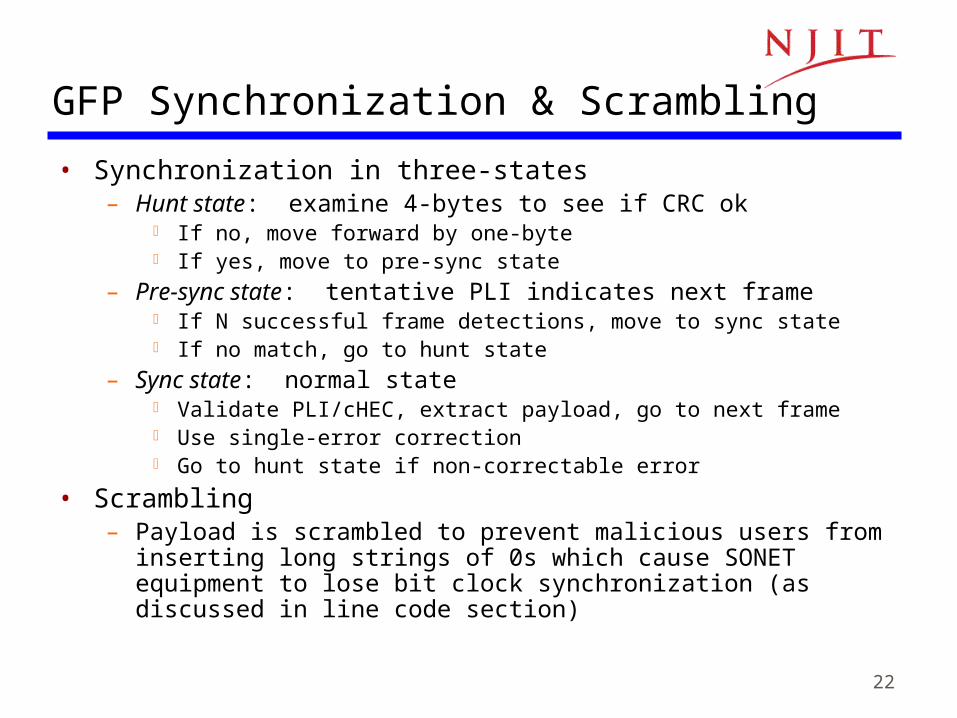
GFP Synchronization & Scrambling
• Synchronization in three-states– Hunt state: examine 4-bytes to see if CRC ok
If no, move forward by one-byte If yes, move to pre-sync state
– Pre-sync state: tentative PLI indicates next frame If N successful frame detections, move to sync state If no match, go to hunt state
– Sync state: normal state Validate PLI/cHEC, extract payload, go to next frame Use single-error correction Go to hunt state if non-correctable error
• Scrambling– Payload is scrambled to prevent malicious users from inserting long
strings of 0s which cause SONET equipment to lose bit clock synchronization (as discussed in line code section)
23
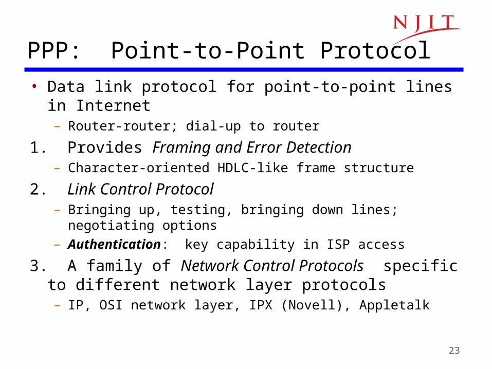
PPP: Point-to-Point Protocol• Data link protocol for point-to-point lines in Internet
– Router-router; dial-up to router
1. Provides Framing and Error Detection– Character-oriented HDLC-like frame structure
2. Link Control Protocol– Bringing up, testing, bringing down lines; negotiating options– Authentication: key capability in ISP access
3. A family of Network Control Protocols specific to different network layer protocols– IP, OSI network layer, IPX (Novell), Appletalk
24
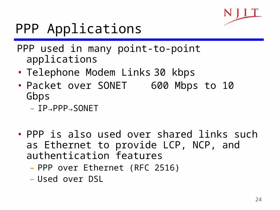
PPP Applications
PPP used in many point-to-point applications• Telephone Modem Links 30 kbps• Packet over SONET 600 Mbps to 10 Gbps
– IP→PPP→SONET
• PPP is also used over shared links such as Ethernet to provide LCP, NCP, and authentication features– PPP over Ethernet (RFC 2516)– Used over DSL

25
• PPP can support multiple network protocols simultaneously• Specifies what kind of packet is contained in the payload
•e.g. LCP, NCP, IP, OSI CLNP, IPX...
PPP Frame Format
Flag FlagAddress Control Information FCSProtocol01111110 0111111011111111 00000011
CRC 16 or CRC 32
1 or 2 variable 2 or 4
All stations are toaccept the frame
HDLC Unnumbered frame
26
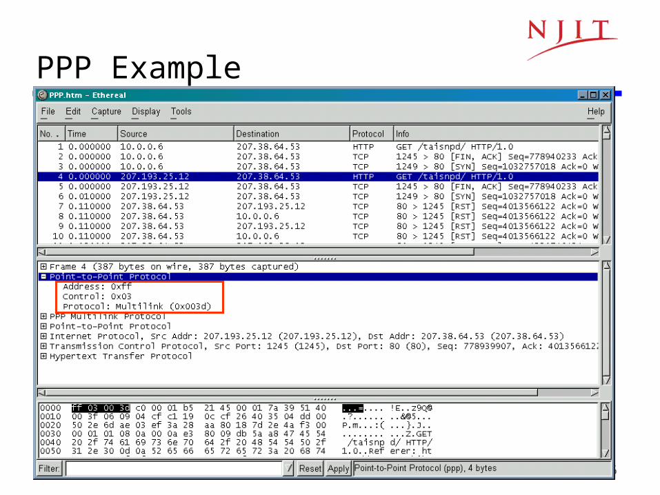
PPP Example

27
PPP PhasesHome PC to Internet Service
Provider1. PC calls router via modem2. PC and router exchange LCP
packets to negotiate PPP parameters
3. Check on identities4. NCP packets exchanged to
configure the network layer, e.g. TCP/IP ( requires IP address assignment)
5. Data transport, e.g. send/receive IP packets
6. NCP used to tear down the network layer connection (free up IP address); LCP used to shut down data link layer connection
7. Modem hangs up
Dead
Establish
Authenticate
Network
Terminate
Open
Failed
Failed
1. Carrier detected
2. Optionsnegotiated
3. Authentication completed4. NCP
configuration
6. Done
7. Carrierdropped
5.
28
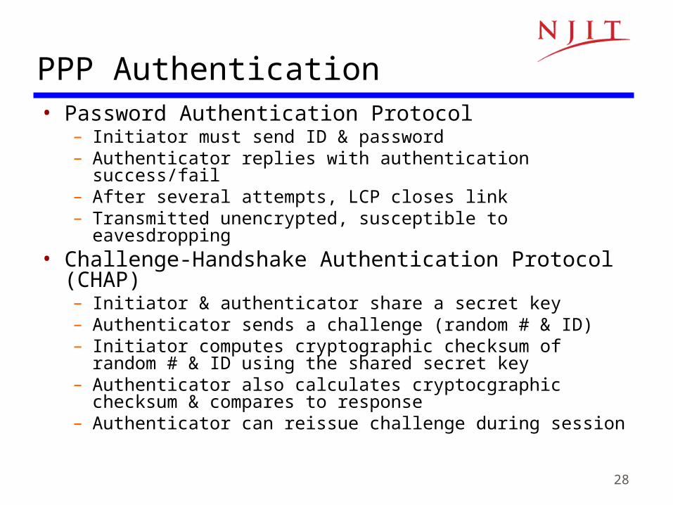
PPP Authentication• Password Authentication Protocol
– Initiator must send ID & password– Authenticator replies with authentication success/fail– After several attempts, LCP closes link– Transmitted unencrypted, susceptible to eavesdropping
• Challenge-Handshake Authentication Protocol (CHAP)– Initiator & authenticator share a secret key– Authenticator sends a challenge (random # & ID)– Initiator computes cryptographic checksum of random # & ID
using the shared secret key– Authenticator also calculates cryptocgraphic checksum &
compares to response– Authenticator can reissue challenge during session
29
High-Level Data Link Control (HDLC)
• Bit-oriented data link control • Derived from IBM Synchronous Data Link
Control (SDLC)• Related to Link Access Procedure Balanced
(LAPB)– LAPD in ISDN– LAPM in cellular telephone signaling

30
Physicallayer
Data linklayer
Data linklayer
Networklayer
DLSDU DLSDU
Networklayer
Physicallayer
DLPDU
NLPDU
“Packet”
“Frame”
DLSAP DLSAP

31
• Normal Response Mode– Used in polling multidrop lines
• Asynchronous Balanced Mode– Used in full-duplex point-to-point links
HDLC Data Transfer Modes
PrimaryCommands
Responses
Secondary Secondary Secondary
Primary
Secondary
Commands Responses
Primary
Secondary
CommandsResponses
• Mode is selected during connection establishment
32
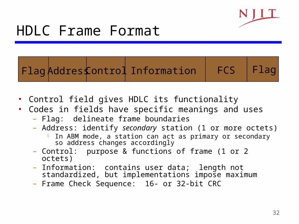
HDLC Frame Format
• Control field gives HDLC its functionality• Codes in fields have specific meanings and uses
– Flag: delineate frame boundaries– Address: identify secondary station (1 or more octets)
In ABM mode, a station can act as primary or secondary so address changes accordingly
– Control: purpose & functions of frame (1 or 2 octets)– Information: contains user data; length not standardized, but
implementations impose maximum– Frame Check Sequence: 16- or 32-bit CRC
Flag FlagAddress Control Information FCS

33
Control Field Format
0 N(S) N(R)P/F
1 2-4 5 6-8
Information Frame
N(R)P/F
Supervisory Frame
1 0 S S
Unnumbered Frame
P/F1 1 M M M M M
• S: Supervisory Function Bits• N(R): Receive Sequence Number• N(S): Send Sequence Number
• M: Unnumbered Function Bits • P/F: Poll/final bit used in interaction
between primary and secondary

34
Information frames• Each I-frame contains sequence number N(S)• Positive ACK piggybacked
– N(R)=Sequence number of next frame expected acknowledges all frames up to and including N(R)-1
• 3 or 7 bit sequence numbering – Maximum window sizes 7 or 127
• Poll/Final Bit– NRM: Primary polls station by setting P=1; Secondary sets
F=1 in last I-frame in response– Primaries and secondaries always interact via paired P/F bits

35
• Frames lost due to loss-of-synch or receiver buffer overflow
• Frames may undergo errors in transmission• CRCs detect errors and such frames are treated as lost• Recovery through ACKs, timeouts & retransmission• Sequence numbering to identify out-of-sequence &
duplicate frames• HDLC provides for options that implement several ARQ
methods
Error Detection & Loss Recovery

36
Supervisory framesUsed for error (ACK, NAK) and flow control (Don’t Send):• Receive Ready (RR), SS=00
– ACKs frames up to N(R)-1 when piggyback not available
• REJECT (REJ), SS=01 – Negative ACK indicating N(R) is first frame not received correctly.
Transmitter must resend N(R) and later frames
• Receive Not Ready (RNR), SS=10– ACKs frame N(R)-1 & requests that no more I-frames be sent
• Selective REJECT (SREJ), SS=11– Negative ACK for N(R) requesting that N(R) be selectively
retransmitted
37
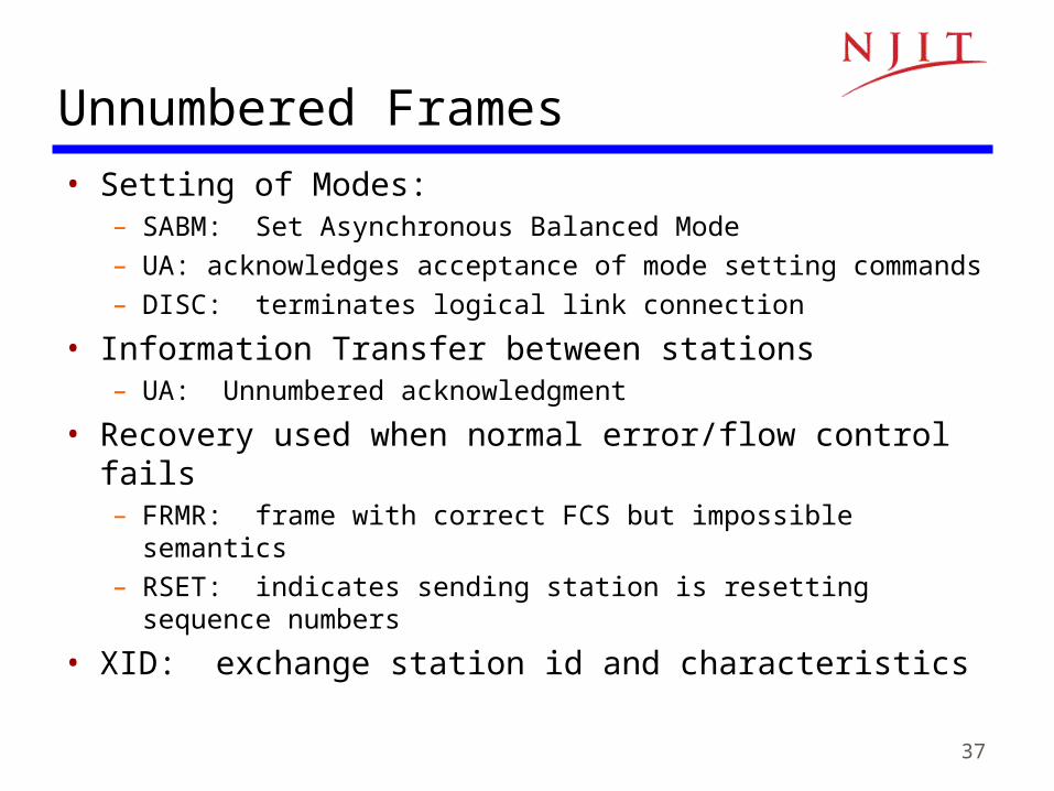
Unnumbered Frames• Setting of Modes:
– SABM: Set Asynchronous Balanced Mode– UA: acknowledges acceptance of mode setting commands– DISC: terminates logical link connection
• Information Transfer between stations– UA: Unnumbered acknowledgment
• Recovery used when normal error/flow control fails– FRMR: frame with correct FCS but impossible semantics– RSET: indicates sending station is resetting sequence numbers
• XID: exchange station id and characteristics

38
Connection Establishment & Release
• Unnumbered frames used to establish and release data link connection
• In HDLC– Set Asynchronous Balanced Mode (SABM)– Disconnect (DISC)– Unnumbered Acknowledgment (UA)
SABM UAUA DISCDatatransfer
39
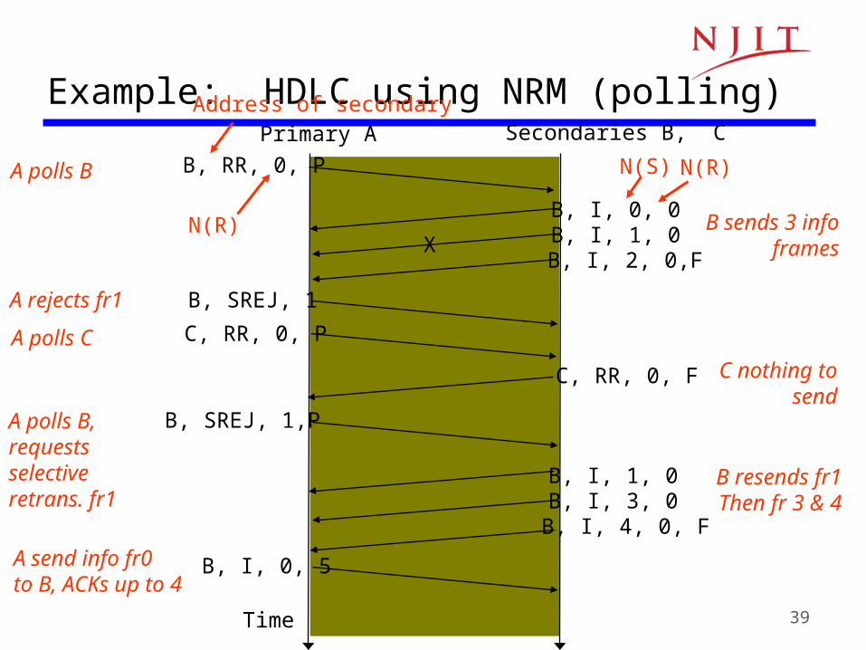
Primary A Secondaries B, C
B, RR, 0, P
B, I, 0, 0B, I, 1, 0B, I, 2, 0,F
X
B, SREJ, 1
C, RR, 0, P
C, RR, 0, F
B, SREJ, 1,P
B, I, 1, 0B, I, 3, 0B, I, 4, 0, F
B, I, 0, 5
Time
Example: HDLC using NRM (polling)
A polls B
B sends 3 infoframes
A rejects fr1
A polls C
C nothing to send
A polls B, requestsselective retrans. fr1
B resends fr1Then fr 3 & 4
A send info fr0to B, ACKs up to 4
N(R)
N(S) N(R)
Address of secondary
40
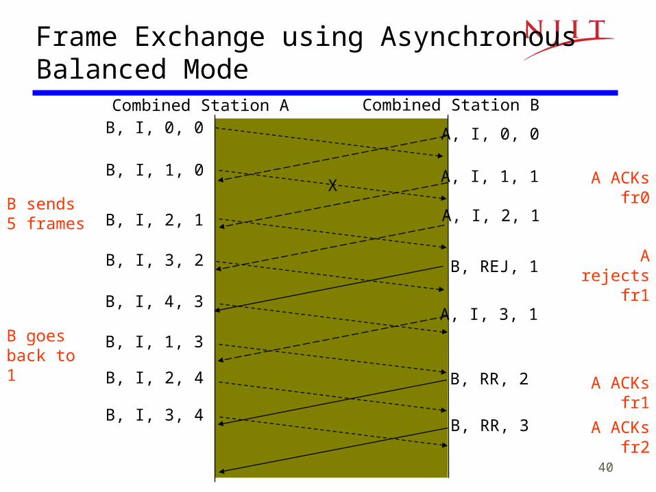
Combined Station A Combined Station BB, I, 0, 0 A, I, 0, 0
B, I, 1, 0
B, I, 2, 1
A, I, 1, 1
A, I, 2, 1
X
B, REJ, 1B, I, 3, 2
B, I, 4, 3
B, I, 1, 3
B, I, 2, 4
B, I, 3, 4
A, I, 3, 1
B, RR, 2
B, RR, 3
Frame Exchange using Asynchronous Balanced Mode
B sends 5 frames
A ACKs fr0
A rejects fr1
B goes back to 1
A ACKs fr1
A ACKs fr2
41
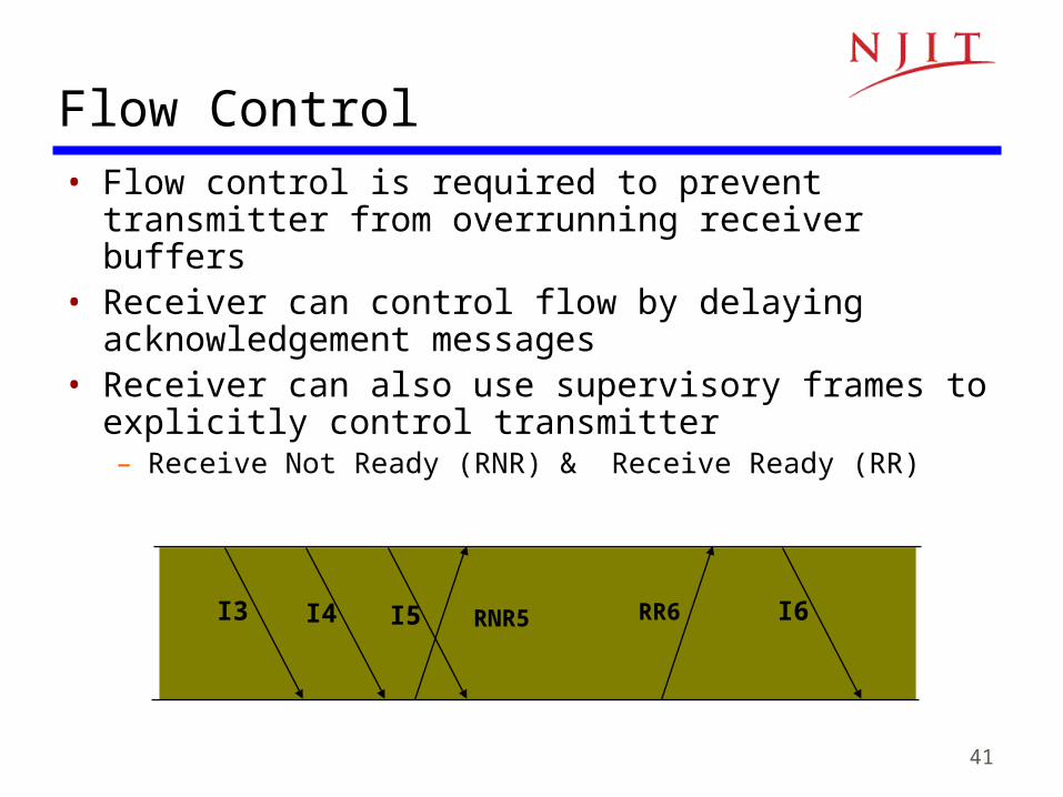
I3 I4 I5 I6RNR5 RR6
Flow Control• Flow control is required to prevent transmitter from
overrunning receiver buffers• Receiver can control flow by delaying acknowledgement
messages• Receiver can also use supervisory frames to explicitly
control transmitter– Receive Not Ready (RNR) & Receive Ready (RR)
42
Further Reading
• Textbook: 3.9.1--3.9.6, 5.1-- 5.6
43
ECE 683Computer Network Design & Analysis
Note 6: Medium Access Control Protocols
44
Outline
• Multiple Access Communications• Random Access
– ALOHA– Slotted ALOHA– Carrier Sense Multiple Access (CSMA)– CSMA with Collision Detection (CSMA-CD)
• Scheduling• Channelization

45
Multiple Access Communications
• Shared media is the basis of broadcast networks– Inexpensive: radio over air; copper or coaxial cable– M users communicate by broadcasting into the medium
• Key issue: How to share the medium?
12
3
4
5M
Shared multipleaccess medium
Broadcast networks are often also referred to as multiple access networks

46
Medium sharing techniques
Static channelization
Dynamic medium access control
Scheduling Random access
Approaches to Media Sharing
• Partition medium
• Dedicated allocation to users
• Satellite transmission
• Cellular Telephone
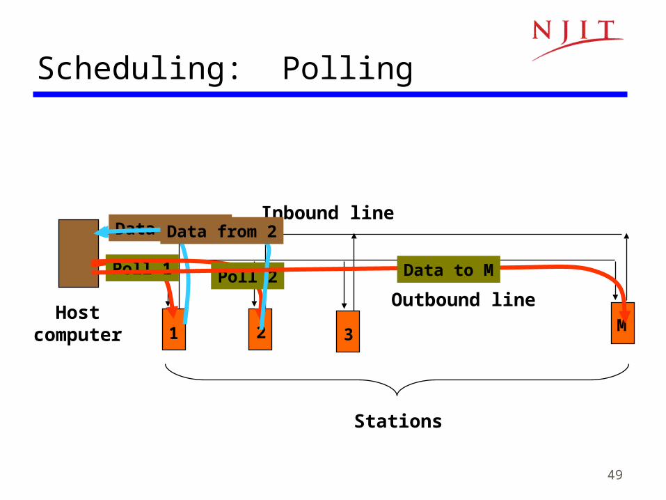
• Polling: take turns
• Request for slot in transmission schedule
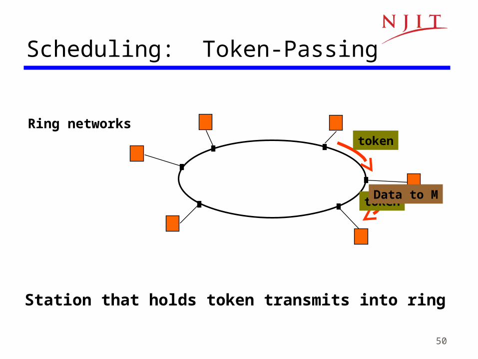
• Token ring
• Wireless LANs
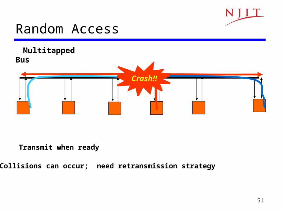
• Loose coordination
• Send, wait, retry if necessary
• Aloha
• Ethernet
MAC protocols
47
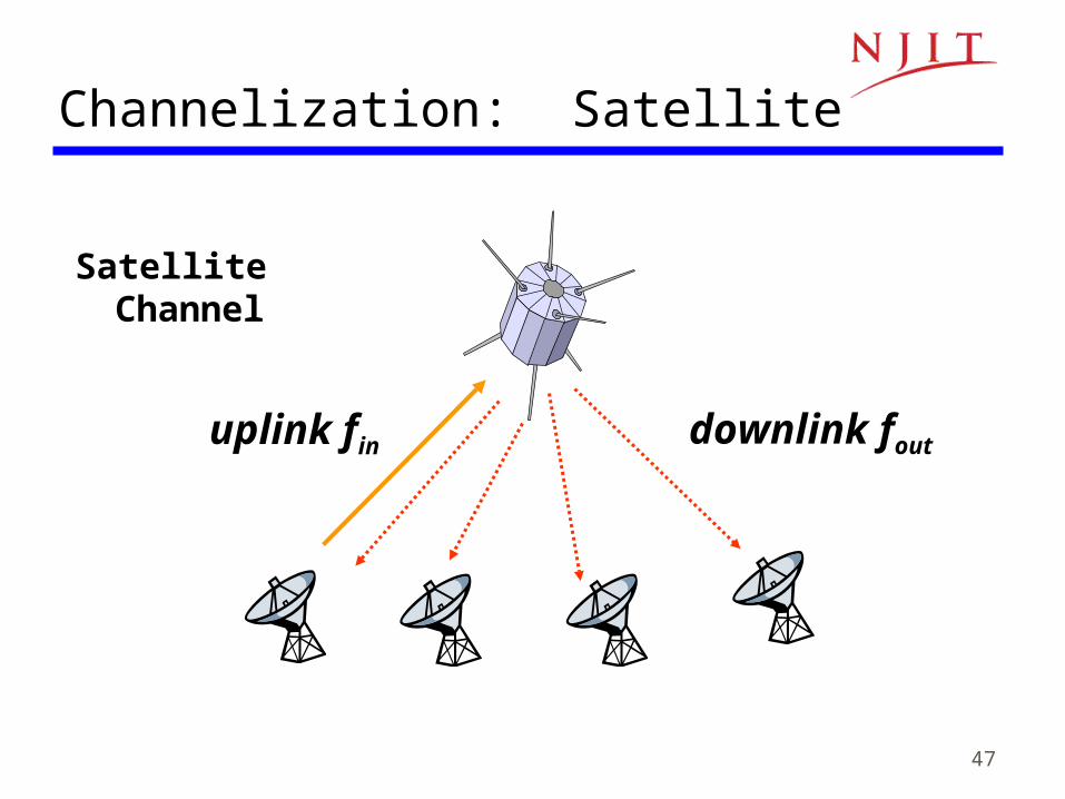
Satellite Channel
uplink fin downlink fout
Channelization: Satellite
48
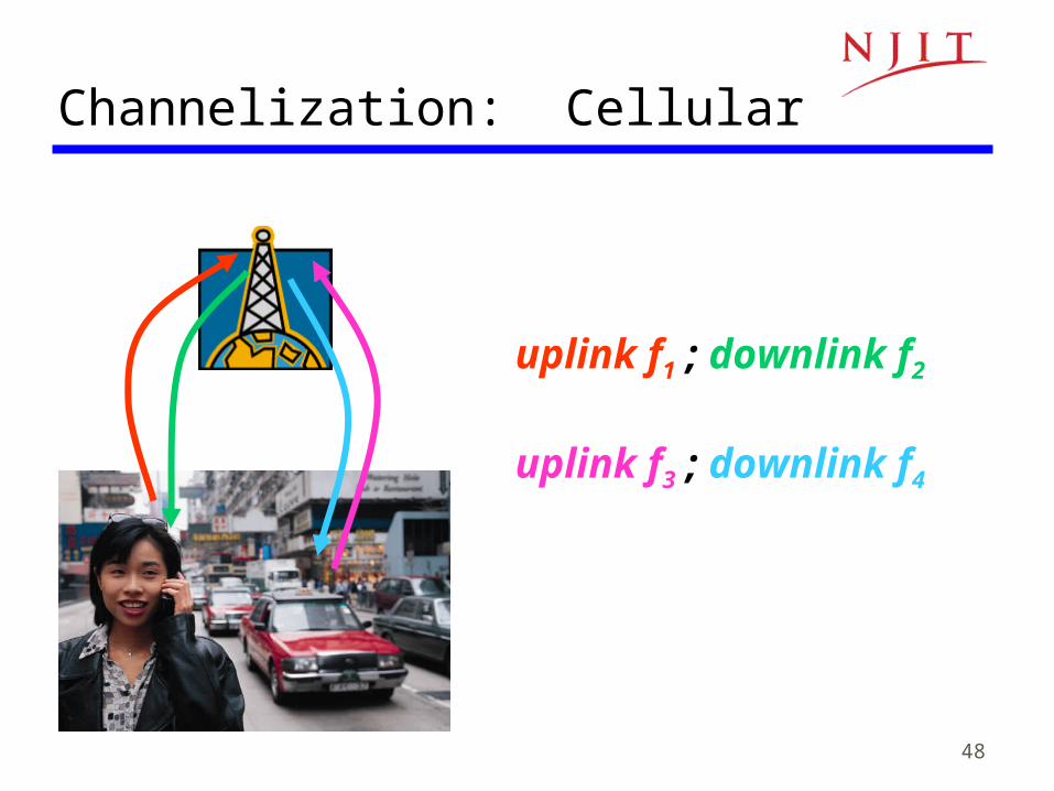
Channelization: Cellular
uplink f1 ; downlink f2
uplink f3 ; downlink f4
49
Inbound line
Outbound lineHost
computer
Stations
Scheduling: Polling
1 2 3 M
Poll 1
Data from 1
Poll 2
Data from 2
Data to M
50
Ring networks
Scheduling: Token-Passing
token
Station that holds token transmits into ring
tokenData to M
51
Multitapped Bus
Random Access
Transmit when ready
Crash!!
Collisions can occur; need retransmission strategy
52
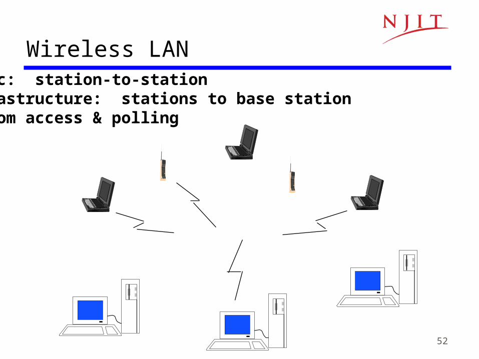
AdHoc: station-to-stationInfrastructure: stations to base stationRandom access & polling
Wireless LAN

53
Delay-Bandwidth Product
• Delay-bandwidth product is the key parameter– Coordination in sharing medium involves using
bandwidth (explicitly or implicitly)– Difficulty of coordination is commensurate with delay-
bandwidth product
• Simple two-station example– Station with frame to send listens to medium and
transmits if medium is found idle– Station monitors medium to detect collision– If collision occurs, station that begin transmitting
earlier retransmits (propagation time is known)
54
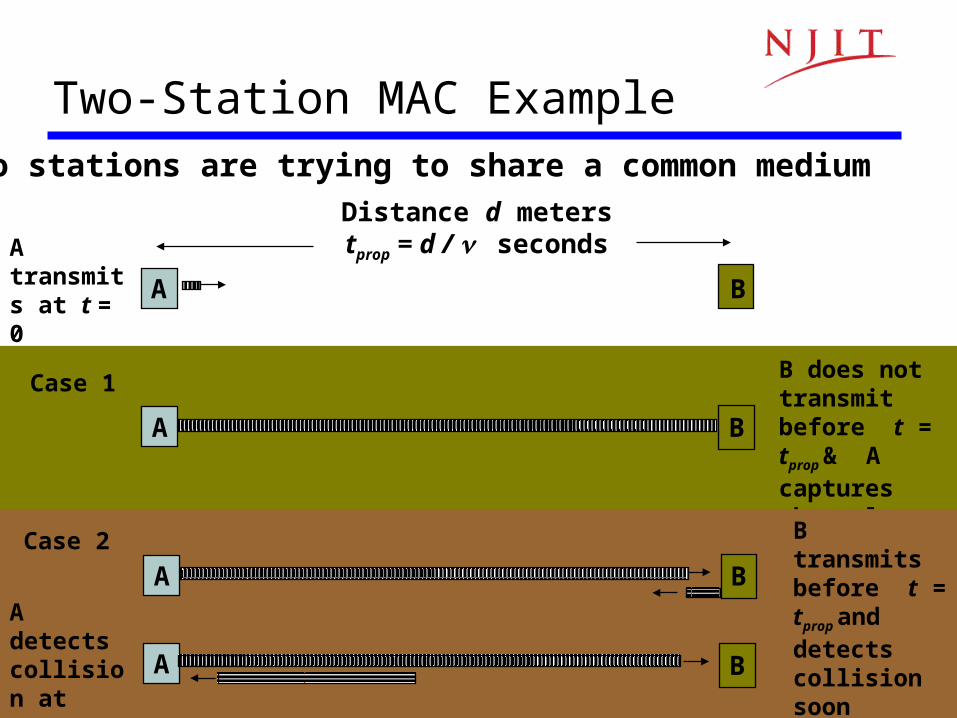
Two stations are trying to share a common medium
Two-Station MAC Example
A transmits at t = 0
Distance d meterstprop = d / seconds
A B
A B
B does not transmit before t = tprop
& A captures channel
Case 1
B transmits before t = tprop and detectscollision soonthereafter
A B
A B
A detectscollision at t = 2 tprop
Case 2
55
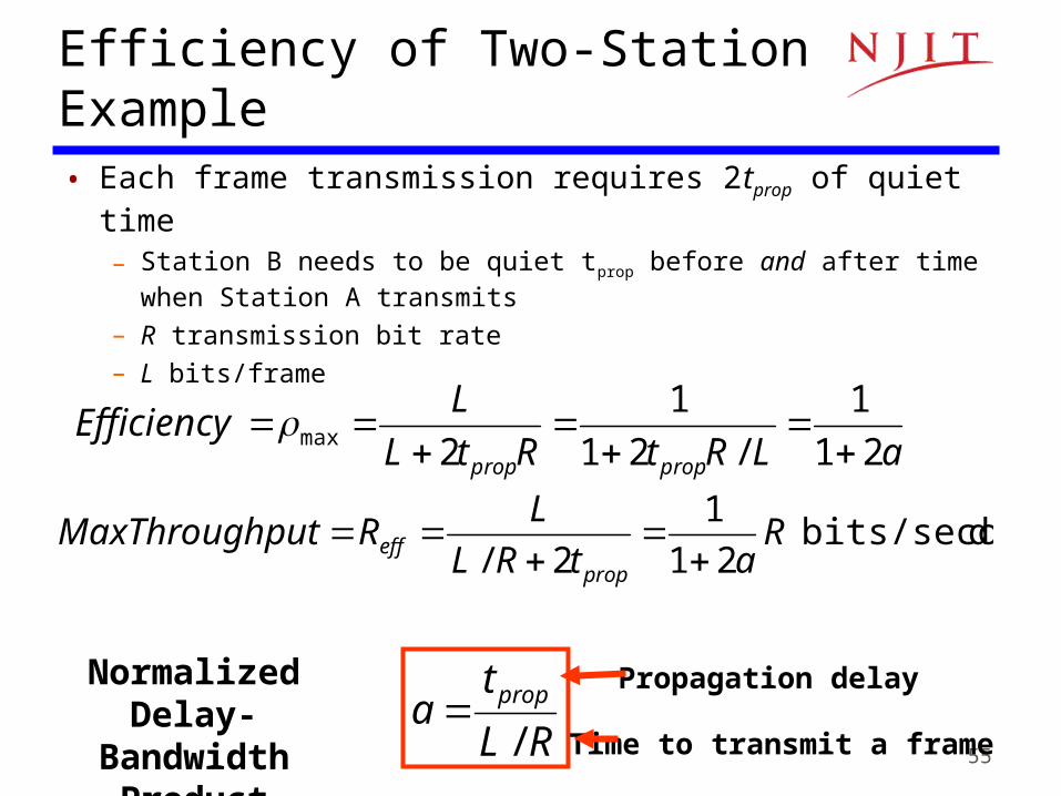
Efficiency of Two-Station Example• Each frame transmission requires 2tprop of quiet time
– Station B needs to be quiet tprop before and after time when Station A transmits
– R transmission bit rate– L bits/frame
aLRtRtL
L
propprop 21
1
/21
1
2max
Efficiency
RL
ta prop
/
Normalized Delay-Bandwidth
Product
dbits/secon 21
1
2/RatRL
LR
propeff
putMaxThrough
Propagation delay
Time to transmit a frame

56
Typical MAC Efficiencies
CSMA-CD (Ethernet) protocol:
Token-ring network
a΄= latency of the ring (bits)/average frame length
Two-Station Example:
a21
1
Efficiency
a44.61
1
Efficiency
a
1
1Efficiency
• If a<<1, then efficiency close to 100%
• As a approaches 1, the efficiency becomes low
57
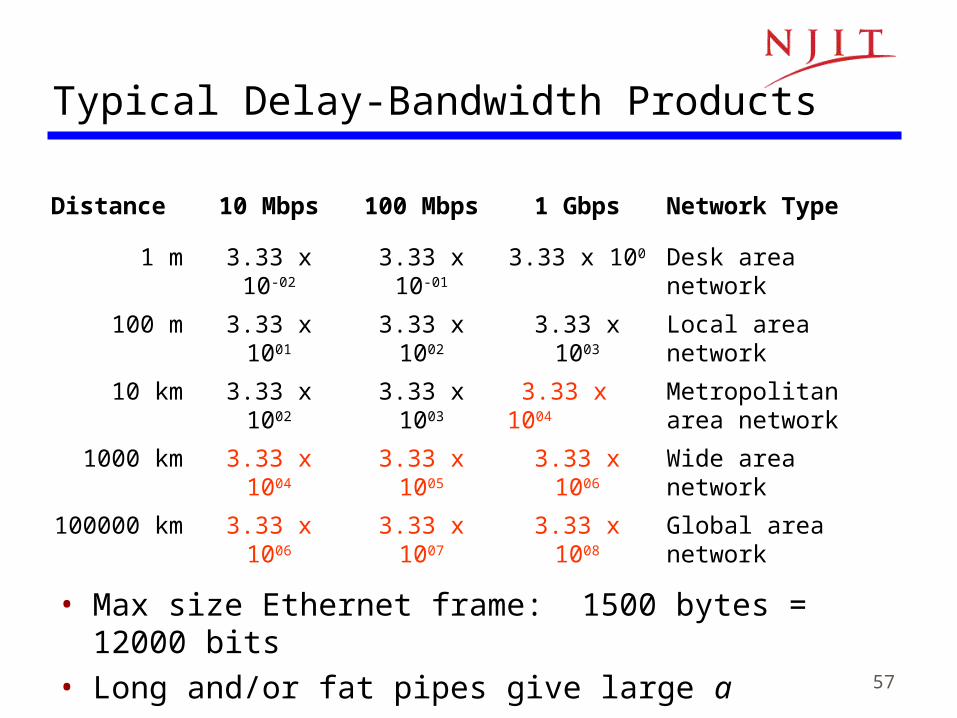
Typical Delay-Bandwidth Products
• Max size Ethernet frame: 1500 bytes = 12000 bits• Long and/or fat pipes give large a
Distance 10 Mbps 100 Mbps 1 Gbps Network Type
1 m 3.33 x 10-02 3.33 x 10-01 3.33 x 100 Desk area network
100 m 3.33 x 1001 3.33 x 1002 3.33 x 1003 Local area network
10 km 3.33 x 1002 3.33 x 1003 3.33 x 1004 Metropolitan area network
1000 km 3.33 x 1004 3.33 x 1005 3.33 x 1006 Wide area network
100000 km 3.33 x 1006 3.33 x 1007 3.33 x 1008 Global area network
58
Factors in Selecting a MAC protocol
• Delay-bandwidth product• Efficiency• Transfer delay• Fairness• Reliability• Capability to carry different types of traffic• Quality of service• Scalability• Cost

59
MAC Delay Performance• Frame transfer delay
– From the first bit of a frame arrives at source MAC– To the last bit of a frame delivered at destination MAC
• Throughput– Actual transfer rate through the shared medium– Measured in frames/sec or bits/sec
• ParametersR bits/sec & L bits/frame frames/second average arrival rateX=L/R sec/frame (frame transmission time)Load = L/R<1, rate at which “work” arrivesMaximum throughput (@100% efficiency): R/L fr/sec
60Load
Tra
ns
fer
del
ay
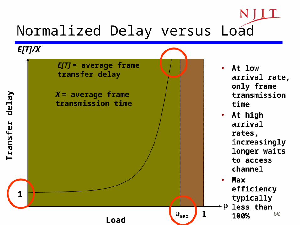
E[T]/X
max 1
1
Normalized Delay versus Load
E[T] = average frametransfer delay
X = average frametransmission time
• At low arrival rate, only frame transmission time
• At high arrival rates, increasingly longer waits to access channel
• Max efficiency typically less than 100%
61
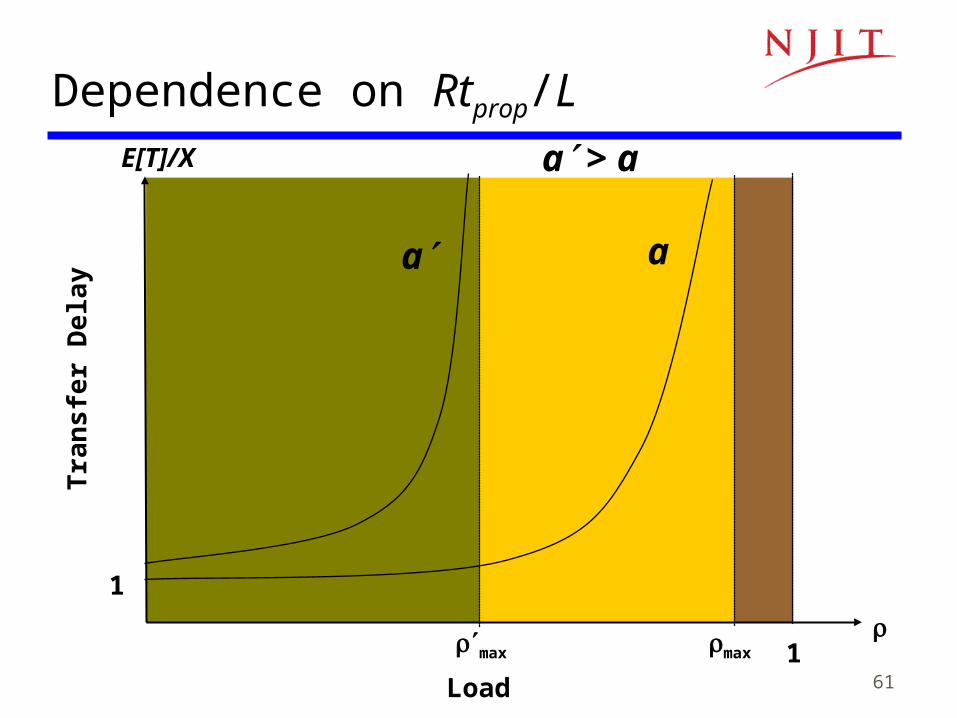
Dependence on Rtprop/LT
ran
sfe
r D
ela
y
Load
E[T]/X
max 1
1
max
aa
a > a