Attitude Determination & Control Technical Training Course Sampler
Upload
cornelius-chaseCategory
view
220download
2
Attitude Determinationand Control System
Peer Review
December 2003
Introduction
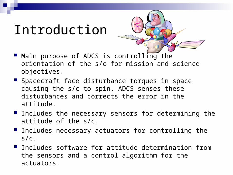
Main purpose of ADCS is controlling the orientation of the s/c for mission and science objectives.
Spacecraft face disturbance torques in space causing the s/c to spin. ADCS senses these disturbances and corrects the error in the attitude.
Includes the necessary sensors for determining the attitude of the s/c.
Includes necessary actuators for controlling the s/c. Includes software for attitude determination from the
sensors and a control algorithm for the actuators.

Requirements
Maintain nadir attitude for communication and imaging objectives.
Perform onboard attitude determination and control. Maintain roll and pitch control using a gravity gradient boom. Maintain attitude knowledge to 2° in every axis. Maintain attitude control to +/- 10 ° in each axis.
Mass 2.25 kgPower 4 W operating
These requirements constitute a fairly coarse ADC system thus the design driving requirements are the mass and power limitations.
Imposed System Requirements
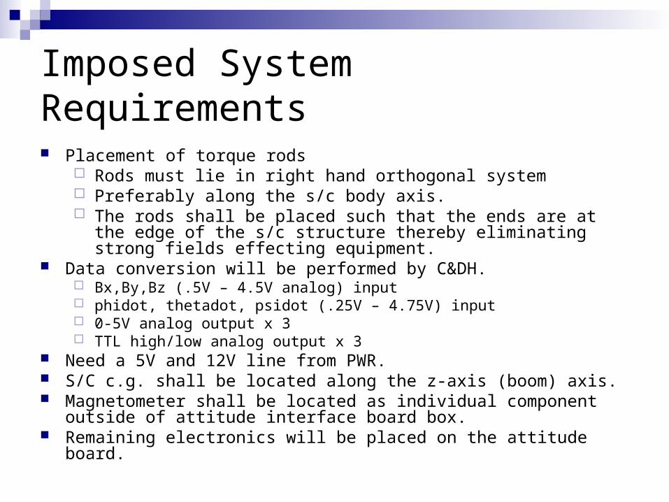
Placement of torque rods Rods must lie in right hand orthogonal system Preferably along the s/c body axis. The rods shall be placed such that the ends are at the edge of the s/c
structure thereby eliminating strong fields effecting equipment. Data conversion will be performed by C&DH.
Bx,By,Bz (.5V – 4.5V analog) input phidot, thetadot, psidot (.25V – 4.75V) input 0-5V analog output x 3 TTL high/low analog output x 3
Need a 5V and 12V line from PWR. S/C c.g. shall be located along the z-axis (boom) axis. Magnetometer shall be located as individual component outside of attitude
interface board box. Remaining electronics will be placed on the attitude board.
Imposed System Requirements
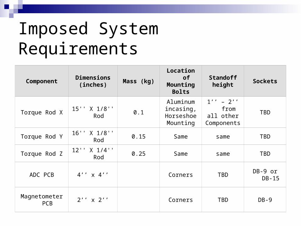
ComponentDimensions
(inches)Mass (kg)
Location ofMounting
Bolts
Standoffheight
Sockets
Torque Rod X 15'' X 1/8'' Rod 0.1
Aluminumincasing,
HorseshoeMounting
1’’ – 2’’ fromall other
ComponentsTBD
Torque Rod Y 16'' X 1/8'' Rod 0.15 Same same TBD
Torque Rod Z 12'' X 1/4'' Rod 0.25 Same same TBD
ADC PCB 4’’ x 4’’ Corners TBDDB-9 or DB-
15
Magnetometer PCB 2’’ x 2’’ Corners TBD DB-9
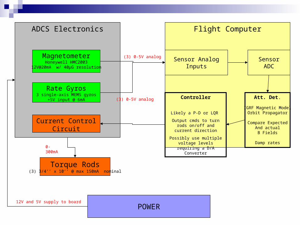
Torque Rods(3) 3/4’’ x 10’’ @ max 150mA nominal
Flight Computer
Att. Det.
IGRF Magnetic ModelOrbit Propagator
Compare ExpectedAnd actualB Fields
Damp rates
Controller
Likely a P-D or LQR
Output cmds to turn rods on/off and current direction
Possibly use multiple voltage levels requiring a D/A
Converter
Sensor AnalogInputs
SensorADC
ADCS Electronics
POWER12V and 5V supply to board
MagnetometerHoneywell HMC2003
12V@20mA w/ 40μG resolution
Rate Gyros3 single-axis MEMS gyros
+5V input @ 6mA
Current ControlCircuit
(3) 0-5V analog
(3) 0-5V analog
0-300mA
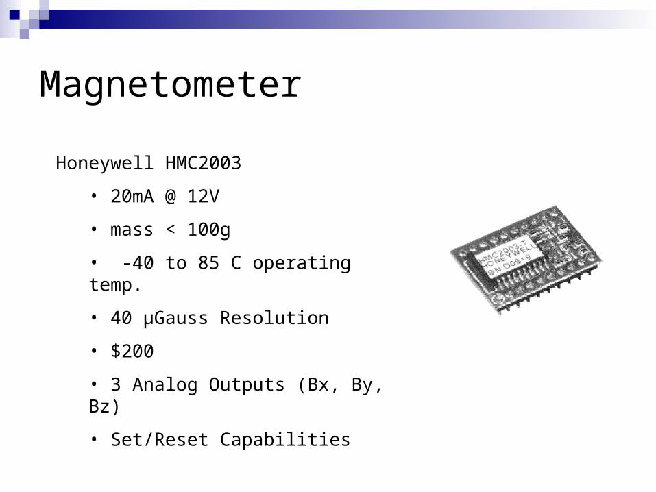
Magnetometer
Honeywell HMC2003
• 20mA @ 12V
• mass < 100g
• -40 to 85 C operating temp.
• 40 μGauss Resolution
• $200
• 3 Analog Outputs (Bx, By, Bz)
• Set/Reset Capabilities
Rate Gyros
Analog Devices ADXRS150EB
Single axis rate gyros provide the rotational rate of the s/c about the output axis
Microchip operating at 5V and 6mA. Single analog output -40 to 85°C operating temp $50 each
Magnetic Torque Rods
Electrical current is passed through wire wound around a ferrous material creating a magnetic dipole moment.
Torquer dipole moment interacts with Earth’s magnetic field to create the desired torques. T = MxB
3 orthogonal torque rods can produce torques perpendicular to magnetic field vector
Unbiased momentum
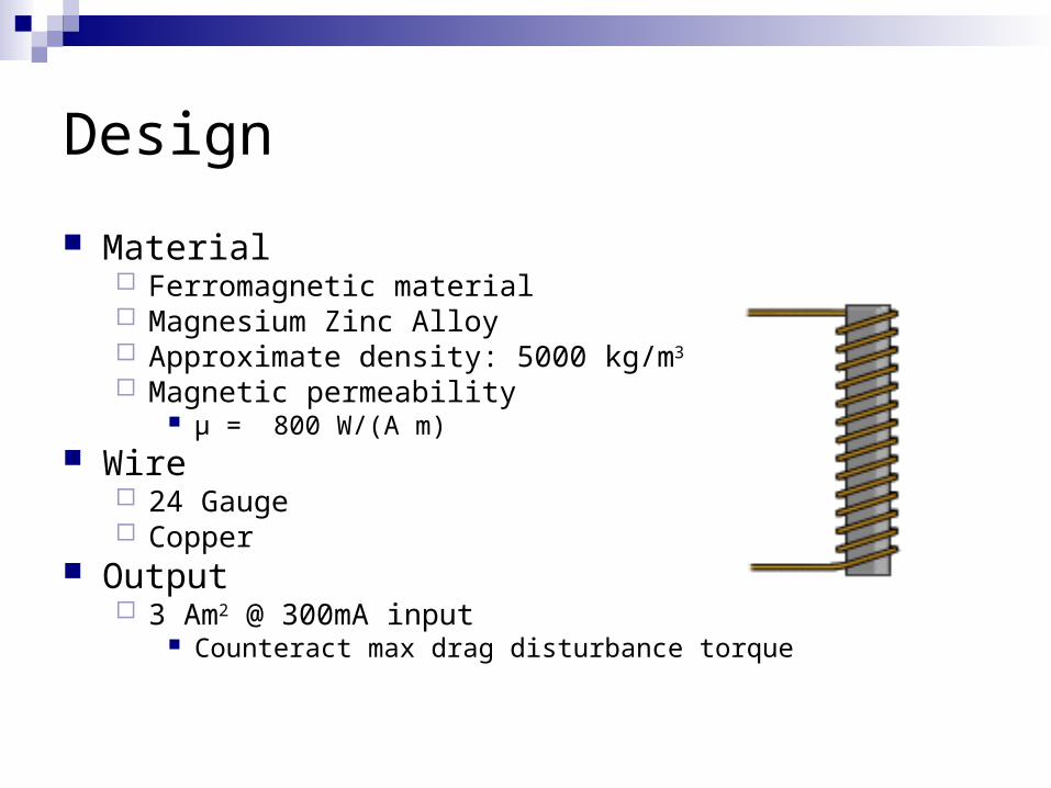
Design
Material Ferromagnetic material Magnesium Zinc Alloy Approximate density: 5000 kg/m3
Magnetic permeability μ = 800 W/(A m)
Wire 24 Gauge Copper
Output 3 Am2 @ 300mA input
Counteract max drag disturbance torque
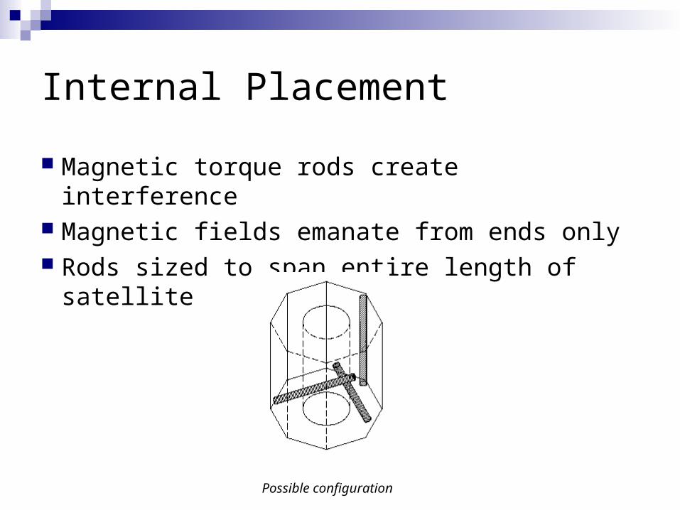
Internal Placement
Magnetic torque rods create interference Magnetic fields emanate from ends only Rods sized to span entire length of
satellite
Possible configuration

Sizing
Design to obtain 5 Am2 @ 500mA Counteract max
drag torques Provide detumbling
capacity
Tradeoffs Weight Power Output Moment
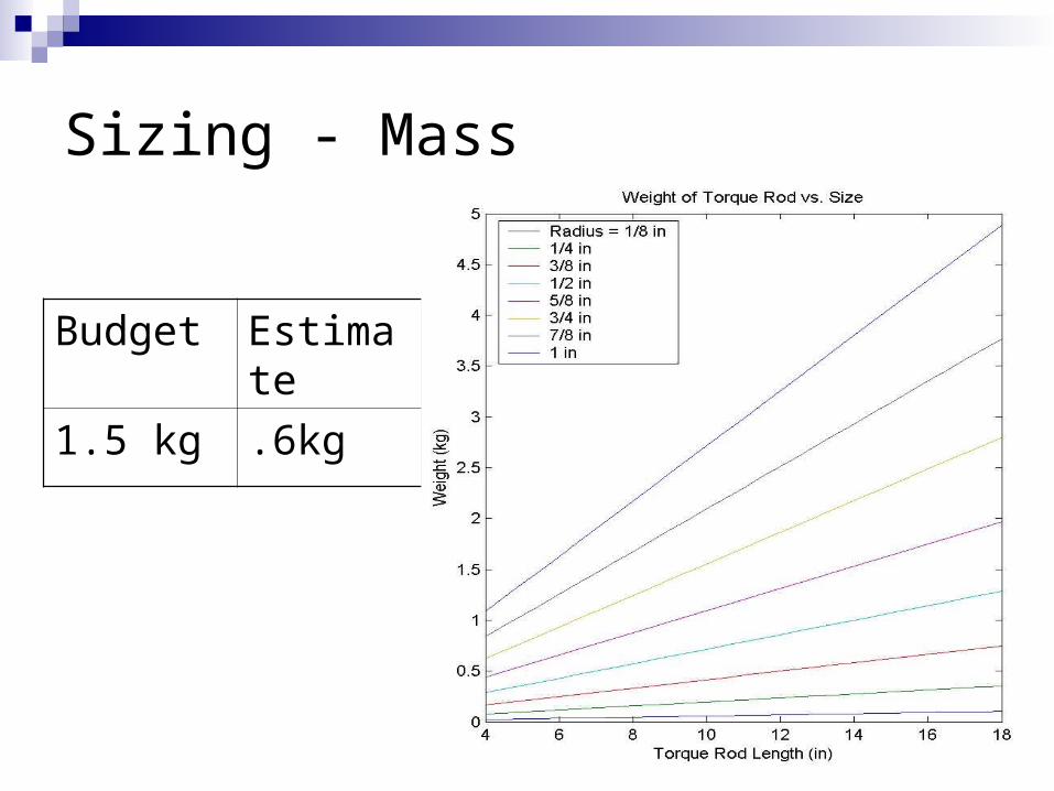
Sizing - Mass
Budget Estimate
1.5 kg .6kg
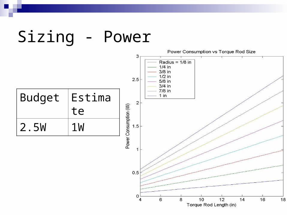
Sizing - Power
Budget Estimate
2.5W 1W
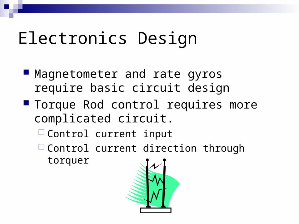
Electronics Design
Magnetometer and rate gyros require basic circuit design
Torque Rod control requires more complicated circuit. Control current input Control current direction through torquer
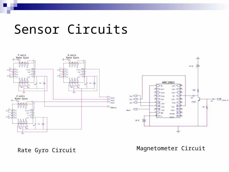
Sensor Circuits
RATEOUT
TEMP
2.5V
AVCC
CP
5
ST
2
ST
1
SU
MJ
CP3
CP4
CP2
CP1
AG
ND
CM
ID
PG
ND
PD
D
9
1
19 2
20
7
11
17
18
14 10 3
4813 12
RATEOUT
TEMP
2.5V
AVCC
CP
5
ST
1
ST
2
SU
MJ
CP3
CP4
CP2
CP1
CM
ID
PG
ND
AG
ND
PD
D
9
19 2
20
7
1
11
17
18
10 3
48
14
13 12
47n
22n
22n
100n
100n 100n
22n
5VDC
47n
22n
22n
100n
100n 100n
22n
5VDC
RATEOUT
2.5V
TEMP
AVCC
CP
5
ST
2
ST
1
SU
MJ
CP3
CP2
CP4
CP1
CM
ID
AG
ND
PD
D
PG
ND
47n
22n
22n
100n
100n 100n
9
219
1
7
17
18
20
311
8
14 10
12 413
22n
5VDC
X-axisRate Gyro
Z-axisRate Gyro
Y-axisRate Gyro
Xout
Yout
Zout
GNDout
Vbridge
SR-
Vsense
Xout Yout
Vref Vbias
SR+
Xoff+
Xoff-
Yoff+Yoff-
Zoff-
V+
GND
Xtrim
Ytrim
Ztrim
HMC2003
12V DC
Zout6
5
4
3
2
1
10
9
8
7
Zoff+20
18
19
16
17
14
15
12
13
11
22u
22u
100k
10k
ZTX605
Xout
Yout
Zout
Reset In
10V DC
GNDout
Rate Gyro Circuit Magnetometer Circuit

Torquer Control Circuit
In+Out+
In-Out-
Torque Rod Control Preliminary Schematic
Direction-TTL
1 2
Vin-Analog
OPAMP
+
-
OUT
Rbias
20
1
2
1
2
Torque Rod
1
2

Software Design
Control system design Hardware control functions Functional test software
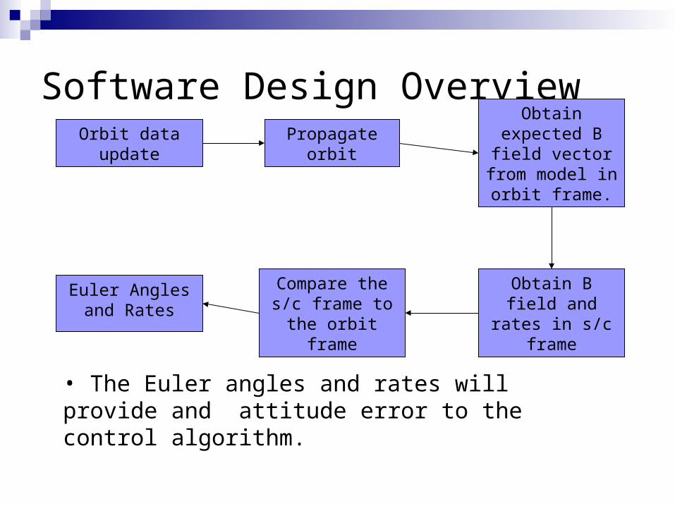
Software Design OverviewOrbit data update Propagate orbit
Obtain expected B field vector from model in orbit frame.
Obtain B field and rates in s/c
frame
Compare the s/c frame to the orbit
frame
Euler Angles and Rates
• The Euler angles and rates will provide and attitude error to the control algorithm.
Software Design Overview Onboard magnetometer data and rotational rate
information. Software-based orbit propagation and magnetic
field model. Partial error analyses has been completed.
Sensitivity of the magnetometer provides negligible attitude knowledge errors on the order of 0.01°.
Tracking data must be uploaded periodically to correct propagation errors.
Bdot data derivations could also be used for comparison between s/c and orbital attitude frames.

Control Design
Based on research paper by Cornell University faculty member.
Simple control law/code Analysis not yet performed.
Primary control design work to be completed during spring semester.
Control design, analysis, simulation, flight code development.
Hardware Control Functions
Control D/A converter for torque rod current control circuit input.
Control of TTL line for current flow direction through torque rod.
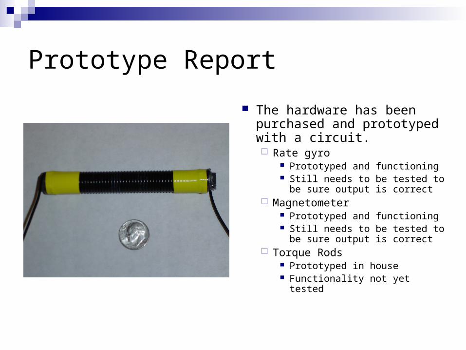
Prototype Report
The hardware has been purchased and prototyped with a circuit. Rate gyro
Prototyped and functioning Still needs to be tested to
be sure output is correct Magnetometer
Prototyped and functioning Still needs to be tested to
be sure output is correct Torque Rods
Prototyped in house Functionality not yet tested

Commands
Torquer On/Off Inputs
X,Y, or Z rod amount of current Direction of current
Outputs digital signal to D/A to vary output voltage of D/A. TTL high/low for control of direction of current.
Commands
Control on/off Either run the control system or do not.
Attitude Board on/off This will provide/cut power to the attitude board
Attitude determination and control will be completely off
Read data Need to read data from sensors and store to
variables.
Test Plans-Hardware
Magnetometer Successfully tested to
be sure it functions Verify the output is
correct with rated magnets
Rate Gyros Successfully tested to
be sure it functions Verify the output is
correct by spinning each rate gyro up on spinning apparatus
Compare angular rate output value to known angular rate value
Test Plans-Hardware
Torque Rods Use magnetometer to
test the amount of torque produced
Graph relationship between current input into current driver circuit and amount of torque produced
Electric Circuits Torque rod current
driver Magnetometer reset
circuit-functions with hardware
Rate Gyro circuit-functions with hardware

Test Plans - Software
Verify orbit propagation vs. STK HPOP Simulate feedback control loop
Provide input torque to simulatorModel will predict s/c reaction to torqueControl loop will provide responseModel can predict time domain responses to
input torques based on control design.