MICROWAVE PHOTONICS APPROACHES FOR 5G STANDARD
62
1 MICROWAVE PHOTONICS APPROACHES FOR 5G STANDARD Emilio Ruiz Torregrosa Supervisor: Beatriz Ortega Tamarit Trabajo Fin de Grado presentado en la Escuela Técnica Superior de Ingenieros de Telecomunicación de la Universitat Politècnica de València, para la obtención del Título de Graduado en Ingeniería de Tecnologías y Servicios de Telecomunicación Curso 2016-17 Valencia, 12 de septiembre de 2017
Transcript of MICROWAVE PHOTONICS APPROACHES FOR 5G STANDARD

1
MICROWAVE PHOTONICS APPROACHES FOR 5G STANDARD
Emilio Ruiz Torregrosa
Supervisor: Beatriz Ortega Tamarit
Trabajo Fin de Grado presentado en la Escuela Técnica
Superior de Ingenieros de Telecomunicación de la
Universitat Politècnica de València, para la obtención
del Título de Graduado en Ingeniería de Tecnologías y
Servicios de Telecomunicación
Curso 2016-17
Valencia, 12 de septiembre de 2017
2
Resumen
El propósito de este Trabajo Fin de Grado es el de presentar diversos sistemas para la
generación de señales de microondas mediante la utilización de técnicas de fotónica de
microondas con el fin de ser empleadas en el nuevo estándar 5G. Para la simulación se ha
empleado el software de simulación VPI photonics. Todos los diseños se basan en el uso de un
modulador Mach-Zehnder polarizado en el punto de mínima transmisión para generar la señal.
Un diseño basado en este método es empleado para transmitir datos NRZ OOK a 10 Gbps sobre
una señal a 30 GHz a partir de un oscilador que emite una señal de 15 GHz. El sistema es
comparado con uno que no emplea técnicas de fotónica de microondas dando un buen resultado
tanto en comportamiento como en coste. Asimismo, se presentan otras alternativas que utilizan
la dispersión estimulada de Brillouin (SBS) para incrementar la frecuencia de la portadora sin
aumentar la frecuencia del oscilador. Por último, se demuestra un esquema que también hace
uso del SBS para generar pulsos triangulares a 5, 8 y 10 GHz; y un esquema que emplea dos
láseres consiguiendo una mayor flexibilidad en la sintonización.
Resum
El propòsit d'aquest Treball Fi de Grau és el de presentar diversos sistemes per a la generació de
senyals de microones per mitjà de la utilització de tècniques de fotònica de microones amb
l'objectiu de ser utilitzades en el nou estàndard 5G. Per a la simulació s'ha disposat del
programari de simulació VPI photonics. Tots els dissenys es basen en l'ús d'un modulador
Mach-Zehnder polaritzat en el punt de mínima transmissió per a generar el senyal. Un disseny
basat en este mètode és empleat per a transmetre dades NRZ OOK a 10 Gbps sobre un senyal a
30 GHz a partir d'un oscil·lador que emet un senyal de 15 GHz. El sistema es compara amb un
que no empra tècniques de fotónica de microones donant un bon resultat tant en comportament
com en cost. Així mateix es presenten altres alternatives que utilitzen la dispersió estimulada de
Brillouin (SBS) per a incrementar la freqüència de la portadora sense augmentar la freqüència
de l'oscil·lador. Finalment, es demostra un esquema que també fa ús del SBS per a generar
polsos triangulars a 5, 8 i 10 GHz; i un esquema que empra dos làsers aconseguint una major
flexibilitat en la sintonització.
Abstract
The aim of this Final Degree Thesis is to present diverse systems for the generation of
microwave signals through the utilization of microwave photonic techniques with the intention
of being employed in the new standard 5G. For the simulation work, VPI photonics simulation
platform software has been utilized. All the designs are based on the use of a Mach-Zehnder
modulator biased at the minimum transmission point to generate the signal. A design based on
this method is employed to transmit NRZ OOK data at 10 Gbps over a 30 GHz signal by an
oscillator which beams a 15 GHz signal. The system is compared with one which does not make
use of microwave photonic techniques giving a satisfactory result both in the behavior and the
cost. Additionally, other alternatives that utilize the Stimulated Brillouin Scattering (SBS) to
increment the carrier frequency without increasing the oscillator frequency are presented.
Lastly, a scheme that also make use of SBS is demonstrated to be able to generate triangular-
shaped pulses at 5,8 and 10 GHz; and a design with two lasers is also demonstrated, achieving
an enhanced flexibility in the tunability.

3
INDEX
Chapter 1. Introduction ................................................................................................................. 4
1.1 Motivation ..................................................................................................................... 4
1.2 Objectives ...................................................................................................................... 4
1.3 Structure ........................................................................................................................ 5
Chapter 2. The future standard 5G ................................................................................................ 6
2.1 Network architecture ..................................................................................................... 7
2.2 Technology .................................................................................................................... 9
2.3 Frequency bands .......................................................................................................... 12
2.4 Transmission Standards ............................................................................................... 15
Chapter 3. The role of microwave photonics .............................................................................. 18
3.1 Radio-over-Fiber (RoF) Transmission ........................................................................ 19
3.1.1 Figures of Merit and RoF Link Limitations ........................................................ 19
3.1.2 RoF role in Virtualized RAN .............................................................................. 20
3.2 Indoor Frequency Up-Conversion RoF Link .............................................................. 20
3.3 RF Signal Photonic Generation ................................................................................... 22
3.4 Optical Conformation .................................................................................................. 26
3.5 Filtering ....................................................................................................................... 27
Chapter 4. System Designs, Simulations and Results ................................................................. 30
4.1 Description of the Software ......................................................................................... 31
4.2 Conventional 10 Gbps NRZ OOK RoF Link .............................................................. 34
4.3 Microwave Photonics based 10 Gbps NRZ OOK RoF Link ...................................... 40
4.4 Optical microwave generator based on SBS with fine tunability ................................ 44
4.5 Photonic generation of triangular-shaped microwave pulses using SBS-based optical
carrier processing .................................................................................................................... 48
4.6 Flexible two lasers RF mm-wave generation system .................................................. 52
Chapter 5. Budget ........................................................................................................................ 55
Chapter 6. Conclusions and Future Lines ................................................................................... 58
6.1 Conclusions ................................................................................................................. 58
6.2 Future Lines ................................................................................................................ 59
References ................................................................................................................................... 60

4
Chapter 1. Introduction
1.1 Motivation
Nowadays, each time more and more devices are being connected to internet, and the
predictions talk about a vast number of connected devices in the near future. Not only mobile
phones, tablets, computers or wearables but also household appliances. It is becoming common
to have more ‘intelligent’ white goods that can be turned on/off without being at home. Future
technologies planned as the vehicle-to-vehicle communication, or the increasing requirements in
terms of bandwidth, data rate and even latency force to look for an improvement of the current
network.
5G is described as the next generation mobile network, however, it is not projected as a
modest improvement over 4G but as an almost completely new network. Therefore, recurrent
researches are carried out to construct the new generation network, which is still immature.
5G has some challenges that must be overcome. Multiple antennas per device will be
common, so the beamforming and steering is very important to enhance the performance, the
efficiency and reduce the interferences. New frequencies must be dedicated as the currents are
very saturated. Studies talk about employing higher frequencies, in the range of microwaves.
Besides, is very important to improve the efficiency.
To beat some issues, microwave photonics is presented as a key technology. This
versatile field is being studied in many researches as the pillar of processes as optical
conformation, filtering or RF signal generation.
In this way, the interest of satisfying the future needs and the promising application of
microwave photonic techniques are the main source of motivation to develop this thesis.
1.2 Objectives
The objective of this thesis is the study of different RF mm-wave signal generation
systems by using microwave photonic techniques with a view to the next generation mobile
network (5G). To achieve this aim, some goals are defined:
• Study and selection of the network architectures proposed, the frequency bands
of interest and the key technologies, in order to know the likely path 5G will
follow.
• Gather the present transmission standards to have a vision of the state of maturity
of the network.
• Define the Radio-over-transmission, discover the main problems of this kind of
links and introduce some indoor networks based on these links.
• Study the potential applications of microwave photonic techniques inside the new
standard.
• Search and investigation of possible designs to generate RF mm-wave signals.
• Learn the basics of VPI photonics, the simulation platform software employed.

5
• Simulate and analyze the viability of the proposed generator systems.
• Estimate the budget of implementing the systems simulated in order to be able to
compare them in economic terms.
1.3 Structure
The thesis is structured in six chapters. The first chapter introduces the motivation to
realize the thesis, as well as its objectives and structure. Throughout the second chapter, the 5G
network is studied. A list of recommended frequency bands is analyzed and, the network
architecture, its technology and transmission standards are commented.
The next chapter discuss about Radio-over-fiber transmission and different microwave
photonic techniques are presented to supply important processes inside the future network as RF
mm-wave signal generation.
Once the theoretical background is explained, is the turn to show the work realized: the
simulation of different RF mm-wave generator systems.
In chapter 5 an estimated budget of implementing the different systems is disaggregated
in order to compare the designs in economic terms
The last chapter gather the conclusions and future investigation lines. Finally, references
complete the thesis.
6
Chapter 2. The future standard 5G
This thesis focuses on the study of the role of the Microwave Photonics in a 5G indoor
network. In order to perform any assessment, it is necessary to have a deep knowledge of the
system under study. Therefore, the system depends on two fundamental pillars: 5G standard and
microwave photonics. This chapter provides the required information in terms of the 5G
standard.
Although the standard is yet under study, there are many researches which agree in
several aspects of the new technology, and they are presented in this thesis. However, it is
remarkable that new or edited requirements in the future could be defined.
The chapter has been divided into the next sections:
• Section 2.1 describes Network architecture
• Section 2.2 presents the Technology
• Section 2.3 describes the recommended Frequency bands
• Section 2.4 introduces the Transmission Standards
7
2.1 Network architecture
In order to support the increasingly data rates, the massive number of devices, the lower
latencies; and to manage the volume of new spectrum (primarily on higher bands) of the 5G
network is necessary a completely new architecture.
Virtualization is a promising technology. With a view to face some of the main
challenges of deploying new services, network operators started to work with Virtual Network
Functions (VNFs). These functions can implement network functions traditionally implemented
via custom hardware appliances and middleboxes. These could be located either in data centers,
network nodes or at end user premises. The basic idea is to execute RAN functionality on more
generic and generally available execution hardware and software platform. However, some
network functions have such strong timing relations with the radio, or depend so strongly that it
is challenging to virtualize them. The question now is: which parts of the RAN are viable to be
executed on a virtualized environment?
Another concept more and more present in 5G is Network Slices. A wide variety of
services, requirements and scenarios is a main feature in 5G networks. Network slicing will help
the operators to address these different use cases efficiently. The idea consists in deploying
multiple logical networks as independent, but using a common physical infrastructure. In this
common infrastructure, the physical network resources are separated from the logical network
through Virtual Network Functions and Software Defined Networking (SDN). A 5G slice could
be composed of a collection of 5G network functions (NF) and specific radio access technology
(RAT) settings that are combined for a specific use case.
Currently, 4G networks have been deployed making use of Distributed and Centralized
RAN. In a D-RAN all processing is performed locally at the access point (AP) while in a C-
RAN all processing is allocated to a central unit (CU). This Central Unit serves multiple
distributed radio sites, and the transmission link between it and the radio units use CPRI
fronthaul over dedicated fiber or microwave links. However, the introduction of high bandwidth
layers’ forces to redesign the RAN architecture. Virtualized RAN exploits the throughput
capabilities and limited coverage of the new spectrum. The Virtualized RAN architecture
leverages NFV techniques and data center processing capabilities and enables coordination and
centralization in mobile networks. It supports cost-efficient processor sharing, scalability, layer
interworking and robust mobility.
There is consensus that 5G logical architecture should foresee a split of control and user
planes. Virtualized RAN allows to realize it enabling individual scalability of both planes and
logical centralized control.
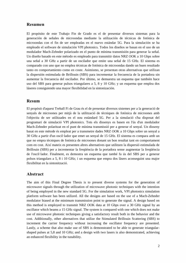
Within the RAN, different considerations on possible function splits are being pursued
(Figure 1):
1. Function split within PHY layer. Its main disadvantage is that the bandwidth
requirements on the fronthaul interface scale with the number of antennas.
2. Function split between PHY and MAC (alternative 1). The advantage is the
lower resulting fronthaul rates, but only MAC-level functions would be
centralized.
3. Function split between synchronous and asynchronous functions (alternative
2). It enables multi-connectivity, exploits eventual pooling gains.
Whatever the functional split point is defined, it is essential that the architecture ideally
supports all the possibilities by leveraging on generic interfaces with varying degrees of traffic
multiplexing and/or routing capabilities.
8
Figure 1. Possible function splits in the RAN.
Indoor Architecture. As 5G is expected to employ mmWave frequencies, it is necessary to
differentiate between indoor and outdoor networks in 5G since the propagation loss through
buildings at these frequencies is very severe.
Although the different technologies mentioned would be able to provide multi-Gb/s
Wireless access, backhaul connectivity to every dwelling is a major challenge. There are two
options: (1) PON based on FTTx technologies and (2) mmWave band backhaul. Passive optical
networks based on fibre is very extended. However, laying down optical fibre to each housing is
expensive in some cases. Point to point backhaul connectivity offers highly flexible, cost
efficient and rapid deployment of multi-Gb/s connectivity. On the other hand, ensuring line-of-
sight in case of mmWave backhauling is difficult in some scenarios.
The architecture referred previously highlights the use of a central unit to manage the
network. Besides, the architecture must define a common infrastructure where the central
processor handles the processing operations leveraging the VNFs. To perform the architecture
described in an indoor scenario, micro C-RAN (mCRAN) architecture has been proposed. It
employs 60 GHz frequency band for high speed indoor communication and RoF technology to
enable centralized base-band processing. Due to the high path loss and the limitation to diffract
around obstacles of the frequency band multiple mmWave APs would be required to cover
indoor areas. Every room becomes a separate 60 GHz cell, therefore frequent handovers can be
unchained. To make network management easy, centrally managed network architecture with
simple access points is desirable.
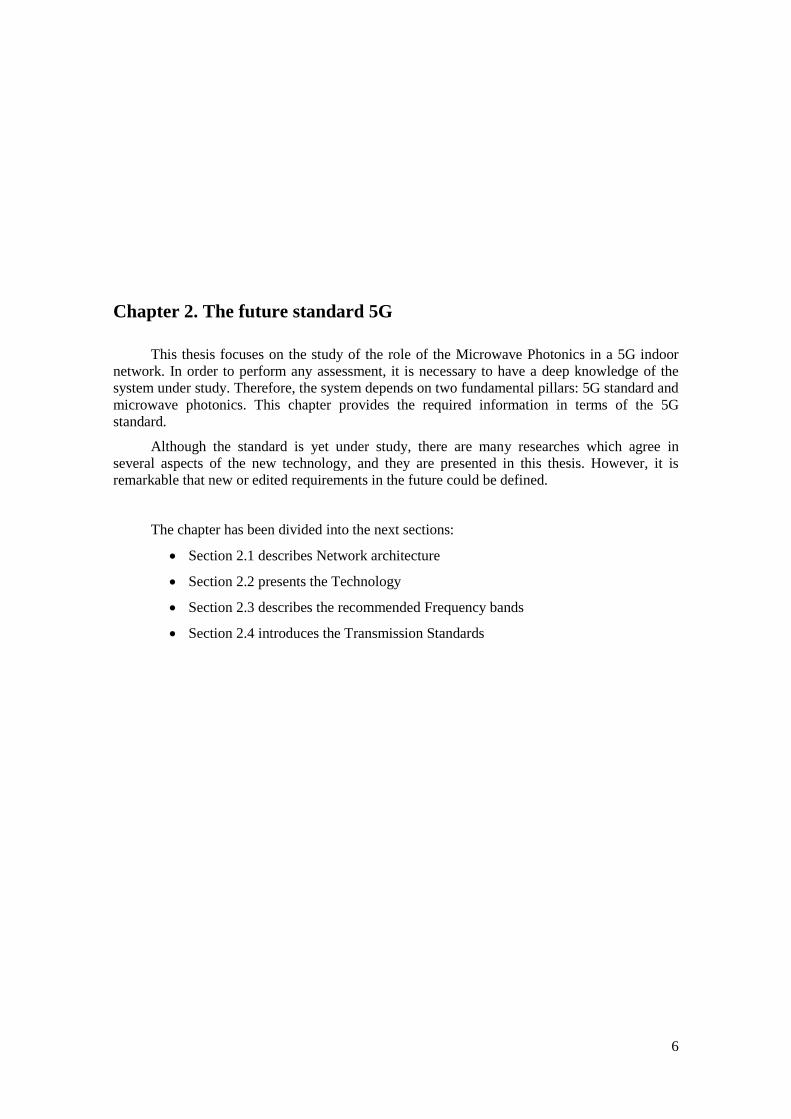
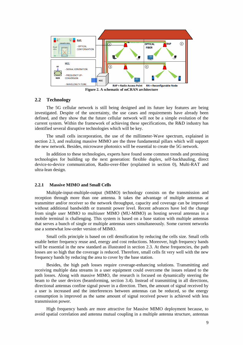
Figure 2 shows the diagram of the outlined architecture. Centralized Home
Communication Controller (HCC) is responsible for radio access control, signal generation,
distribution and processing. Each room has at least one Radio Access Point (RAPs) with radio
beam-steering controlled by the HCC. The connection between the HCC and the RAPs is
realized through optical fibre via the Reconfiguration Nodes (RNs). Depending on HCC’s
instructions, the RN and RAP perform routing/reconfigurable bandwidth allocation and beam-
steering, OE/EO-Conversion, respectively. The RN is a remote process unit whose
responsibility is to configure the RAP.
From HCC to RAP it is necessary to count on separate control channels for beamforming
mechanism in synchronization with the data channel. For short range communications at 60
GHz IEEE 802.11 ad has proposed threes PHYs: Control PHY (27.5Mbps), SC PHY and
OFDM PHY (7 Gb/s). Timing in IEEE 82.11 ad is based on beacons intervals. Inside a beacon
interval we find different access periods having different medium access rules (CSMA/CA and
TDMA).
9
Figure 2. A schematic of mCRAN architecture
2.2 Technology
The 5G cellular network is still being designed and its future key features are being
investigated. Despite of the uncertainty, the use cases and requirements have already been
defined, and they show that the future cellular network will not be a simple evolution of the
current system. Within the framework of achieving these specifications, the R&D industry has
identified several disruptive technologies which will be key.
The small cells incorporation, the use of the millimeter-Wave spectrum, explained in
section 2.3, and realizing massive MIMO are the three fundamental pillars which will support
the new network. Besides, microwave photonics will be essential to create the 5G network.
In addition to these technologies, experts have found some common trends and promising
technologies for building up the next generation: flexible duplex, self-backhauling, direct
device-to-device communication, Radio-over-fiber (explained in section 0), Multi-RAT and
ultra-lean design.
2.2.1 Massive MIMO and Small Cells
Multiple-input-multiple-output (MIMO) technology consists on the transmission and
reception through more than one antenna. It takes the advantage of multiple antennas at
transmitter and/or receiver so the network throughput, capacity and coverage can be improved
without additional bandwidth or transmit power level. Recent advances have led the change
from single user MIMO to multiuser MIMO (MU-MIMO) as hosting several antennas in a
mobile terminal is challenging. This system is based on a base station with multiple antennas
that serves a bunch of single or multiple antennas users simultaneously. Some current networks
use a somewhat low-order version of MIMO.
Small cells principle is based on cell densification by reducing the cells size. Small cells
enable better frequency reuse and, energy and cost reductions. Moreover, high frequency bands
will be essential in the new standard as illustrated in section 2.3. At these frequencies, the path
losses are so high that the coverage is reduced. Therefore, small cells fit very well with the new
frequency bands by reducing the area to cover by the base station.
Besides, the high path losses require coverage-enhancing solutions. Transmitting and
receiving multiple data streams in a user equipment could overcome the issues related to the
path losses. Along with massive MIMO, the research is focused on dynamically steering the
beam to the user devices (beamforming, section 3.4). Instead of transmitting in all directions,
directional antennas confine signal power in a direction. Then, the amount of signal received by
a user is increased and the interferences between antennas can be reduced, so the energy
consumption is improved as the same amount of signal received power is achieved with less
transmission power.
High frequency bands are more attractive for Massive MIMO deployment because, to
avoid spatial correlation and antenna mutual coupling in a multiple antenna structure, antennas

10
must be spaced at least the half wavelength of the radio signal. At millimeter-wave, the number
of antenna elements in the access points could be even more than 1000.
On this basis, it could be claimed that small cells, mm-Wave spectrum and massive
MIMO fit perfectly. In [1], the feasibility to combine small cells and Massive MIMO is studied.
2D antenna array system (AAS) presents similar coverage but additional high SINR region in
low density small cell case to that of omnidirectional antenna. In high density case, the 2D AAS
obtains much better coverage due to the amount of ICI introduced by the omnidirectional
antenna. In [2], a 3D-MIMO design is proposed. The structure is composed with 128 antenna
elements and is designed to work at 2.6 GHz frequency band. Moreover, field trials are
performed showing that it can help 5G to achieve the spectral efficiency target.
2.2.2 Flexible Duplex
Since the beginning of mobile communication, Frequency Division Duplex (FDD) has
become the dominant network duplex technology because the most popular service in mobile
networks requires symmetrical traffic loads for DL and UL. Inside the 5G goals we can find the
dynamic asymmetric resource provision between up- and downstream traffic. In comparison
with FDD, Time Division Duplex (TDD) benefit the system with more flexibility to adapt time-
domain resources with ratio between UL and DL traffics, lower hardware cost and the unpaired
band allocation. However, not all are advantages and some challenging issues have been
identified.
The trend for duplex technology in the next generation will be the convergence of FDD
and TDD in what is called flexible duplex[3]. Furthermore, in stablished TDD network the same
DL/UL subframe configuration is adopted to avoid inter-cell interference between UL and DL
signals. With flexible duplex, any subframe may either be allocated for UL and DL transmission
for a certain cell in a dynamic way. This leads to an improved system throughput.
In conclusion, FDD will remain the main duplex scheme for lower frequencies and long
cover areas whereas TDD is a better choice in small cells, asymmetric traffic and unpaired
spectrum case[4].
2.2.3 Self-Backhauling
Backhaul connectivity could be realized via wireless or wired technology. In the context
of 5G cellular network, a fundamental challenge is to provide an economical and ubiquitous
backhaul connectivity to these small cells. As the access link will extend to higher frequencies,
access and backhaul will share the same wireless channel (self-backhauling).
This enables efficient usage of frequency resources, higher cost efficiency and higher
performance. However, it induces additional interference, complex scheduling of the channel
resources and potential limitation on the end user experience due to the sharing of resources.
Research in this area is being realized to discover the challenges, solutions and possibilities of
this technology[5], [6]. An option to avoid or reduce the new interferences is the use of
interference management strategy as proposed in [7].
2.2.4 Direct Device-to-Device Communication
Device-to-device (D2D) communication commonly refers to a kind of technology that
enables direct communication between devices without communication infrastructures[8]. With
the accelerating growth of Machine-to-Machine (M2M) applications, D2D is being accepted as
a part of the fourth generation. In the 5G era, D2D communications should be a part of the
overall wireless-access solution. It is expected to provide, not only peer-to-peer user-data direct
communication, but also network coverage expansion using mobile devices.
11
It presents a variety of challenges as the efficiently radio resources reallocation among
cellular and D2D users, and the prevention or control of the interferences inside the cellular
system. Several studies ([9], [10]) analyze diverse ways to try to overcome these issues.
Moreover, energy efficiency is a key objective as the battery in mobile devices is limited. In
[11], a study of D2D transmission for use in 5G cellular networks shows that this scheme is
more effective in regards to power and connection efficiency. It improves the system throughput
and can reduce the traffic loads.
2.2.5 Multi-Radio Access Technology (Multi-RAT)
The fifth generation will suppose a substantial twist from the current networks. For 5G
two RAT options can be foreseen. On the one hand, we find a single unified RAT with such
flexibility that can be optimized for different frequencies and use cases through parameter
configuration. This flexibility is still technically challenging, and the maturity of LTE/LTE-A
could make economically inviable the new RAT deployment. To solve these inconvenient, the
other possibility is the utilization of multiple RATs, each of them with a different air interface,
which complement each other acting as a single unit. It seems technically easier to achieve and
more economically viable.
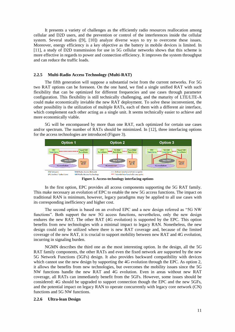
5G will be encompassed by more than one RAT, each optimized for certain use cases
and/or spectrum. The number of RATs should be minimized. In [12], three interfacing options
for the access technologies are introduced (Figure 3).
Figure 3. Access-technology interfacing options
In the first option, EPC provides all access components supporting the 5G RAT family.
This make necessary an evolution of EPC to enable the new 5G access functions. The impact on
traditional RAN is minimum, however, legacy paradigms may be applied to all use cases with
its corresponding inefficiency and higher cost.
The second option is based on an evolved EPC and a new design referred as “5G NW
functions”. Both support the new 5G access functions, nevertheless, only the new design
endures the new RAT. The other RAT (4G evolution) is supported by the EPC. This option
benefits from new technologies with a minimal impact to legacy RAN. Nonetheless, the new
design could only be utilized where there is new RAT coverage and, because of the limited
coverage of the new RAT, it is crucial to support mobility between new RAT and 4G evolution,
incurring in signaling burden.
NGMN describes the third one as the most interesting option. In the design, all the 5G
RAT family components, the other RATs and even the fixed network are supported by the new
5G Network Functions (5GFs) design. It also provides backward compatibility with devices
which cannot use the new design by supporting the 4G evolution through the EPC. As option 2,
it allows the benefits from new technologies, but overcomes the mobility issues since the 5G
NW functions handle the new RAT and 4G evolution. Even in areas without new RAT
coverage, all RATs can immediately benefit from the 5GFs. However, some issues should be
considered: 4G should be upgraded to support connection though the EPC and the new 5GFs,
and the potential impact on legacy RAN to operate concurrently with legacy core network (CN)
functions and 5G NW functions.
2.2.6 Ultra-lean Design
12
The basic principle is to minimize any transmission not directly related to the user data
delivery. These include signals for synchronization, idle-mode mobility and system and control
information [13]. The design enables higher data rates by reducing interference from non-user
data related transmissions. Moreover, it improves the energy performance as it enables network
nodes to stay at low-energy states in longer situations.
In [14], the energy performance of 5G RAT systems characterized by ultra-lean design
and massive beamforming is evaluated and compared with an LTE system in a dense urban
scenario. A decreased energy consumption of more than 50% is expected from 2020. Lean
transmission is important for all kinds of deployments, although especially for the dense one.
2.3 Frequency bands
The radio spectrum is a limited resource that must be efficiently exploited. Although the
5G standard specifications are not definitely defined yet, it exists a consensus around the
utilization of the millimeter-wave (mmWave) spectrum as one of the 5G fundamental pillars
[15], [16]. In the LTE standard, all the frequency bands employed are lower than 6 GHz. 2100,
1800, 2600, 800, 700 and 2300 MHz frequency bands are the most common around the world.
Nowadays, spectrum below 1 GHz has already a very intensive use. Moreover, it is well
accepted by the industry that an order of 1 GHz bandwidth per operator will be necessary,
although 500 MHz could be considered if really needed [17]. Therefore, it is evident that the 5G
standard will have to resort to spectrum bands above 6 GHz, to which we will referred as
‘mmW’ from now on. The main idea is to continue utilizing frequency bands around the 4G
bands, overall in macrocell outdoor scenarios, while spectrum bands above 6 GHz will provide
high data rate, overall in microcell indoor scenarios.
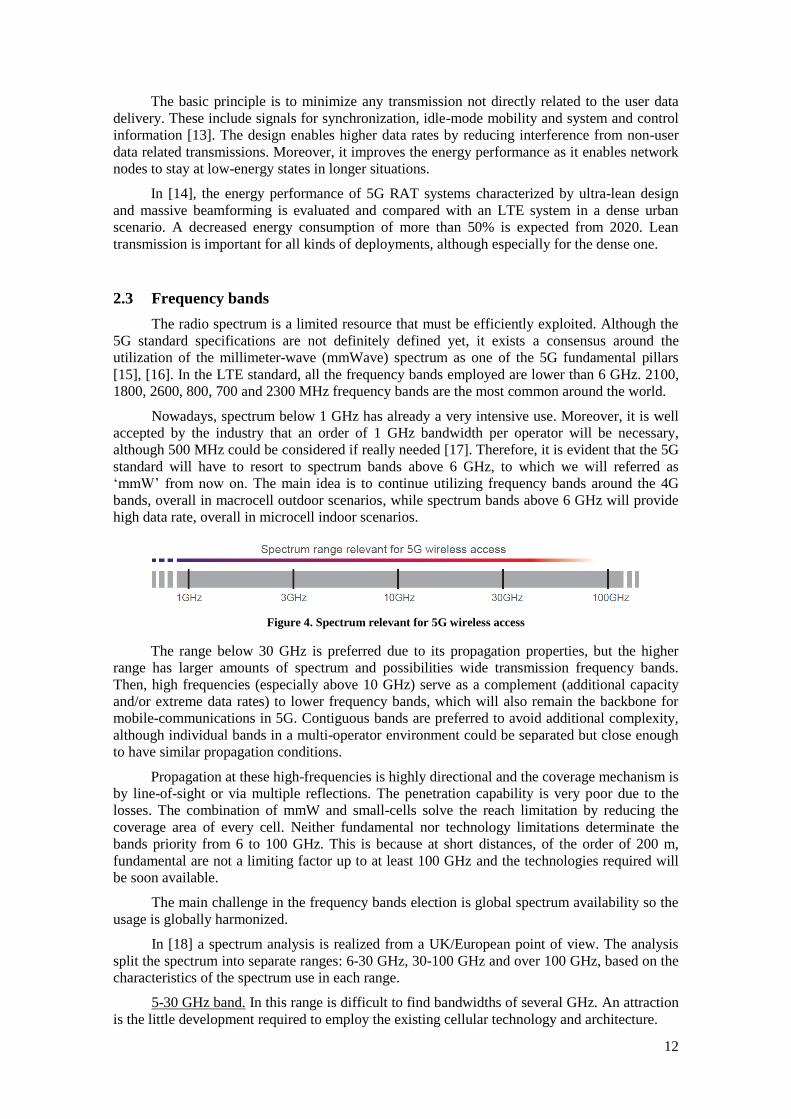
Figure 4. Spectrum relevant for 5G wireless access
The range below 30 GHz is preferred due to its propagation properties, but the higher
range has larger amounts of spectrum and possibilities wide transmission frequency bands.
Then, high frequencies (especially above 10 GHz) serve as a complement (additional capacity
and/or extreme data rates) to lower frequency bands, which will also remain the backbone for
mobile-communications in 5G. Contiguous bands are preferred to avoid additional complexity,
although individual bands in a multi-operator environment could be separated but close enough
to have similar propagation conditions.
Propagation at these high-frequencies is highly directional and the coverage mechanism is
by line-of-sight or via multiple reflections. The penetration capability is very poor due to the
losses. The combination of mmW and small-cells solve the reach limitation by reducing the
coverage area of every cell. Neither fundamental nor technology limitations determinate the
bands priority from 6 to 100 GHz. This is because at short distances, of the order of 200 m,
fundamental are not a limiting factor up to at least 100 GHz and the technologies required will
be soon available.
The main challenge in the frequency bands election is global spectrum availability so the
usage is globally harmonized.
In [18] a spectrum analysis is realized from a UK/European point of view. The analysis
split the spectrum into separate ranges: 6-30 GHz, 30-100 GHz and over 100 GHz, based on the
characteristics of the spectrum use in each range.
5-30 GHz band. In this range is difficult to find bandwidths of several GHz. An attraction
is the little development required to employ the existing cellular technology and architecture.

13
There is strong interest from the satellite industry as well as for the fixed service. Sharing
with both industries is likely to be challenging and would offer limited bandwidth. The band
identified above 30 GHz has greater bandwidth and less sharing issues. Despite, there is a strong
interest in 28 GHz band from the USA, Korea and Japan the ITU-R has not proposed it as a
need for study band before WRC-19[19].
30-100 GHz band. Passive, fixed, MoD and collective use dominate this band. Besides,
the exclusive civil bands are too small for independent 5G mmW use.
There is more bandwidth available than in lower ranges, with potentially more sparse
coexistence concerns. In this range, we found the band 60 GHz with an oxygen absorption peak
within which WiGig systems have been developed, and the 70/80 GHz bands. The lasts may be
attractive since the same operators might wish to operate access and backhaul in-band and to
handle the coordination challenges themselves.
The most important bands are the following:
- The 66-71GHz band has a mobile allocation which is unused. The band is wide and
close to the WiGig band, therefore low-cost technology should be available. Although, no use is
known, it is also allocated to GNSS and ISS. Then collective use is proposed, as at higher
frequencies the probability of interference decrease.
Furthermore, this band is allocated to mobile in at least Europe, China, Japan, South
Korea and USA.
- The 45.4-48.9 GHz band includes two relatively small exclusive bands used for the
Amateur service and PMSE. The PMSE band may be suitable for removal since no allocations
were made, but the Amateur service has a clear usage. Nevertheless, avoiding these bands there
is still 2.8 GHz available non-contiguously.
45.5-47 GHz is allocated to RNSS but unused. Vodafone has suggested the wider range
43-47 GHz could be considered for 5G mmW, however, 43.5-45.5 GHz is an harmonised
NATO band, with potential for future mobile use. As the previous band, these bands could also
be suitable for collective use.
- The 40.5-43.5 band is the concatenation of two bands where the 40.5-42.5 GHz portion
has no primary mobile allocation in Europe. Despite this, the low usage opened it to the fixed
service. Anyhow it continues to be low used, so it could be reconsidered for 5G mmW access.
- The 71-76 and 81-86GHz are typically light licensed bands, but they are relatively
suitable for backhaul. Point-to-point fixed links is their global main usage. Interference could
appear between 5G backhaul and the access networks for the users so a frequency plan would be
needed. Operators might want to self-coordinate between their own access and backhaul
networks in portions of this band.
- The 57-66 GHz license exempt band has spurred the creation of the Wi-Fi Alliance’s
WiGig. This allocation is available globally, but 5G mmW could enter this band directly via
collective use. However, the power/antenna limits may need to be re-assessed for outdoor
operation at 200m.
Above 100 GHz band. This band contains several water and oxygen absorption peaks.
This range remains of interest because of the huge bandwidths which are possible. Although it
would be appropriate due to its disuse, pre-existing allocations should be respected. Over the
next 5 years this band may be best suited for backhaul as the cost point of backhaul best
supports the specialized technology required.
There are many unavailable passive bands, and much of the remainder is allocated to the
Radio Astronomy Service. The residual bands have the potential to support backhaul for 5G
mmW but its range will be limited by atmospherics. Besides, maybe there is already enough
fixed link spectrum.

14
Ou
t/In
do
or
Ou
tdo
or/
Ind
oor
Ind
oor
Ind
oor
Ou
tdo
or
Ou
tdo
or/
Ind
oor
Ou
tdo
or
Ind
oor
Ou
tdo
or
Co
ns
Fu
ture
use
for
inte
r-sa
tell
ite
lin
ks
aris
e
Th
ere
are
excl
usi
ve
civil
sub
-ban
ds
wh
ich
mu
st b
e av
oid
ed. In
Jap
an a
nd
Ch
ina,
th
e w
hole
ban
d m
ay i
s n
ot
sup
po
rted
Glo
bal
use
. In
Euro
pe,
the
low
er 2
GH
z
has
only
a s
econ
dar
y m
ob
ile
allo
cati
on
, n
ow
aday
s op
ened
to
fix
ed
lin
ks.
In
US
A a
nd
Jap
an t
her
e is
not
mo
bil
e al
loca
tio
n i
n t
he
upp
er 1
GH
z
Glo
bal
use
. C
om
mo
nly
use
d f
or
bac
kh
aul.
Shar
ing
may
dec
reas
e
reli
abil
ity
, u
nle
ss s
elf-
bac
kh
auli
ng
is
imple
men
ted
Glo
bal
use
. C
urr
entl
y a
llo
cate
d f
or
wid
eban
d d
ata,
th
en i
ts u
se c
ou
ld s
top
the
sco
pe
for
inno
vat
ion
by c
om
pet
ing
wit
h W
iGig
Glo
bal
inte
nsi
ve
use
. It
is
alre
ady
satu
rate
d.
Lit
tle
ban
dw
idth
av
aila
ble
.
Glo
bal
use
. C
oex
iste
nce
bet
wee
n
serv
ice
is s
till
un
kn
ow
n.
Glo
bal
use
. R
ang
e li
mit
ed b
y
atm
osp
her
ics.
Mu
st r
espec
t th
e R
AS
Pro
s
Glo
bal
ly a
vai
lable
. W
ide
ban
dw
idth
;
mult
iple
oper
ators
pote
nti
al.
Few
shar
ing c
hal
lenges
. H
arm
oniz
atio
n
pote
nti
al
45.5
-47 G
Hz
glo
bal
ly a
vai
lable
. W
ide
ban
dw
idth
; m
ult
iple
oper
ators
pote
nti
al.
Har
moniz
atio
n p
ote
nti
al.
Wid
e ban
dw
idth
; co
uld
support
mult
iple
oper
ators
. C
oll
ecti
ve
use
would
be
appro
pri
ate.
Wid
e ban
dw
idth
. G
ood h
arm
oniz
atio
n
pote
nti
al.
Pote
nti
al t
o u
se v
ia e
xte
nsi
ons
to l
ight
lice
nsi
ng
Wid
e ban
dw
idth
. G
ood h
arm
oniz
atio
n
pote
nti
al.
Good p
ropag
atio
n p
roper
ties
; lo
w p
ath
loss
es
Hig
h i
nte
rest
fro
m t
he
US
A,
Japan
and
Kore
a. L
ess
pat
h l
oss
es
Pote
nti
al u
se t
o s
upport
bac
khau
l
Usa
ge
know
n
No
use
know
n, but
allo
cate
d t
o G
NS
S,
ISS
Rad
io A
mat
eur
Ser
vic
e an
d
PM
SE
Mo
bil
e al
loca
tion i
s
seco
ndar
y. In
Euro
pe
Fix
ed S
ervic
e, b
ut
low
use
.
In U
SA
Fix
ed S
atel
ite
Sy
stem
. In
Jap
an P
MS
E
Po
int-
to-p
oin
t fi
xed
lin
ks
glo
bal
ly
59
-64
co
mm
on g
lobal
wid
eban
d d
ata
sub
-ban
d
Mo
bil
e al
loca
tions
exis
t but
satu
rate
d.
Fix
ed S
atel
ite
and f
ixed
links
Pas
siv
e ban
ds
and R
adio
Ast
rono
my S
ervic
e (R
AS
)
Fre
q B
and
66-7
1 G
Hz
45
.4-4
8.9
GH
z
40
.5-4
3.5
GH
z
71-7
6 a
nd
81-8
6 G
Hz
57-6
6 G
Hz
Bel
ow
6
GH
z
28
GH
z
Ab
ov
e 1
00
GH
z
Table 1. Suitable frequency bands for the 5G standard
15
2.4 Transmission Standards
Previous sections speak about industry agreement in terms of architecture and
technology, or possible interesting frequency bands for 5G network. Moreover, different
microwave photonic techniques are described in the following sections. However, they are all
proposals or recommendation. It is important to point out what is already standardized by the
sector.
In [20], ITU-R defines the framework and overall objectives of the future development of
International Mobile Telecommunications (IMT) for 2020 and beyond (IMT-2020). The
objective of the recommendation is to determine the foundations for IMT-2020 by analyzing the
growth, technological and application trends, as well as, potential user and spectrum
implications.
IMT-2020 must support emerging new use cases. They are useful to resolve which will
be the minimum requirements. On that basis, some of the most important trends will be the
support of very low latency and high reliability human-centric communication (instantaneous
connectivity), very low latency and high reliability machine-centric communication (M2M
communication), high user density (satisfactory end-user experience in crowded events), high
mobility at high mobility; enhanced multimedia services (media delivery with higher data
rates); Internet of Things (connected devices growth); convergence of applications; and ultra-
accurate positioning applications.
Many of these applications are derived from the future IMT traffic growth. Report ITU-R
M.2370 estimates an increase in the range of 10-100 times from 2020 to 2030. The
recommendation M.2083-0 also provides the technology trends mentioned in section 2.2.
Moreover, it is pointed out the need to consider higher frequency ranges (between 6 and 100
GHz) what has led to the different studies on technical feasibility as the referred in section 2.3.
During the World Radiocommunication Conference 2015 (WRC-15) several aspects related to
the radio spectrum resources. In Resolution 238 (WRC-15) [21] ITU-R invited to complete in
time for WRC-19 compatibility studies for an amount of frequency bands in the frequency
range between 24.25 GHz and 86 GHz.
ITU-R list three main usage scenarios for IMT-2020: enhanced mobile broadband, ultra-
massive machine type communications and reliable and low latency communications. The first
one is linked to the increasing demand for mobile broadband together with new application
areas and requirements. About massive machine type communications, future is envisioned as a
world completely connected through a number of smart devices (Internet of Things). Lastly,
ultra-reliable and low latency communications such as remote medical surgery should be
supported.
Minimum technical requirements for IMT-2020 could be achieved with current IMT
through enhancements, new components, technology and functionalities. Besides, services
should be available anywhere, anytime. Thus, interworking between IMT-2020 and existing
IMT, and between other radio systems is indispensable.
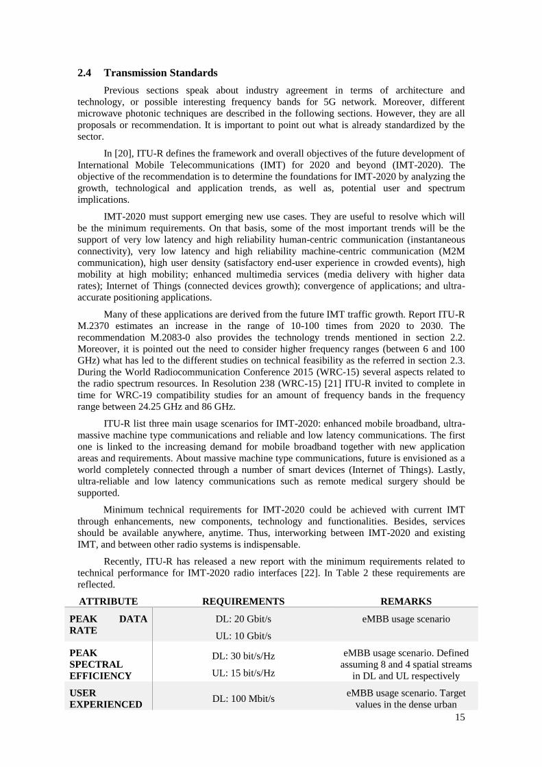
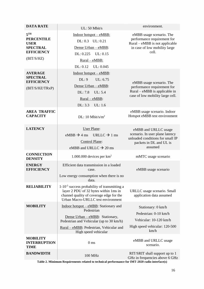
Recently, ITU-R has released a new report with the minimum requirements related to
technical performance for IMT-2020 radio interfaces [22]. In Table 2 these requirements are
reflected.
ATTRIBUTE REQUIREMENTS REMARKS
PEAK DATA
RATE
DL: 20 Gbit/s
UL: 10 Gbit/s
eMBB usage scenario
PEAK
SPECTRAL
EFFICIENCY
DL: 30 bit/s/Hz
UL: 15 bit/s/Hz
eMBB usage scenario. Defined
assuming 8 and 4 spatial streams
in DL and UL respectively
USER
EXPERIENCED DL: 100 Mbit/s
eMBB usage scenario. Target
values in the dense urban
16
DATA RATE UL: 50 Mbit/s
environment.
5TH
PERCENTILE
USER
SPECTRAL
EFFICIENCY
(BIT/S/HZ)
Indoor hotspot – eMBB:
DL: 0.3 UL: 0.21
Dense Urban – eMBB:
DL: 0.225 UL: 0.15
Rural – eMBB:
DL: 0.12 UL: 0.045
eMBB usage scenario. The
performance requirement for
Rural – eMBB is not applicable
in case of low mobility large
cell.
AVERAGE
SPECTRAL
EFFICIENCY
(BIT/S/HZ/TRxP)
Indoor hotspot – eMBB:
DL: 9 UL: 6.75
Dense Urban – eMBB:
DL: 7.8 UL: 5.4
Rural – eMBB:
DL: 3.3 UL: 1.6
eMBB usage scenario. The
performance requirement for
Rural – eMBB is applicable in
case of low mobility large cell.
AREA TRAFFIC
CAPACITY DL: 10 Mbit/s/m2
eMBB usage scenario. Indoor
Hotspot eMBB test environment
LATENCY User Plane:
eMBB 4 ms URLLC 1 ms
Control Plane:
eMBB and URLLC 20 ms
eMBB and URLLC usage
scenario. In user plane latency
unloaded conditions for small IP
packets in DL and UL is
assumed
CONNECTION
DENSITY 1.000.000 devices per km2 mMTC usage scenario
ENERGY
EFFICIENCY
Efficient data transmission in a loaded
case.
Low energy consumption when there is no
data.
eMBB usage scenario
RELIABILITY 1-10-5 success probability of transmitting a
layer 2 PDU of 32 bytes within 1ms in
channel quality of coverage edge for the
Urban Macro-URLLC test environment
URLLC usage scenario. Small
application data assumed
MOBILITY Indoor hotspot – eMBB: Stationary and
Pedestrian
Dense Urban – eMBB: Stationary,
Pedestrian and Vehicular (up to 30 km/h)
Rural – eMBB: Pedestrian, Vehicular and
High speed vehicular
Stationary: 0 km/h
Pedestrian: 0-10 km/h
Vehicular: 10-120 km/h
High speed vehicular: 120-500
km/h
MOBILITY
INTERRUPTION
TIME
0 ms eMBB and URLLC usage
scenario.
BANDWIDTH 100 MHz
RIT/SRIT shall support up to 1
GHz in frequencies above 6 GHz Table 2. Minimum Requirements related to technical performance for IMT-2020 radio interface(s)

17
Until 2020 it is not expected to have the standard defined. To meet this objective, and in
order to planning the development this timeline is considered:
Figure 5. Timeline for the development of IMT-2020

18
Chapter 3. The role of microwave photonics
Once the 5G standard is introduced, it is necessary to get introduced in the role that
microwave photonics can play inside the standard. Microwave photonics is a mature
multidisciplinary engineering field that attempts to utilize the properties of photonic
technologies to improve the performance of microwave/wireless systems [16]. The properties of
the field make it a perfect candidate to help in the implementation of the technology.
There are many possibilities under study to be employed inside the 5G network.
Throughout this chapter distinct roles will be introduced.
The chapter has been divided into the next sections:
• Section 3.1 introduces the Radio-over-Fiber (RoF) Transmission
• Section 3.2 introduces two Indoor Frequency Up-conversion RoF Link Schemes
• Section 3.3 introduces the RF Signal Photonic Generation
• Section 3.4 introduces the Optical Conformation
• Section 3.5 introduces the Filtering
19
3.1 Radio-over-Fiber (RoF) Transmission
Inside the indoor architecture shown in section 2.1, microwave photonics plays a
significant role. The small-cell wireless system described is also referred as Distributed Antenna
System (DAS). In the scheme, fiber is used to distribute the cellular signals, captured on the
roof of a building or received through optic-fiber, to each floor. The transport scheme employed
is Radio-over-Fiber (RoF).
A RoF link consists of a directly or externally modulated laser, where one or more analog
electrical signal placed at different microwave frequencies is imposed to an optical carrier, and a
detector after the optical fiber link, where the microwave signal is recovered from the optical
carrier[23]. Its principal features are the capability to easily support multiple wideband signals
(multiple operators and multiple services), centralized frequency channel management, central
office (CO) equipment sharing and the simpler antenna remote units (ARUs) as no frequency
conversion is required[16].
3.1.1 Figures of Merit and RoF Link Limitations
To evaluate the performance of these links a set of figures of merit (FOM) are typically
considered: the RF link gain (GRF), the noise figure (NF) and the spurious free dynamic range
(SFDR). GRF in RoF links is defined as the ratio of the RF power delivered to a matched load at
the photodetector output, PRF|OUT, to the available RF power at the input, PRF|IN, delivered to the
modulation device, both at the modulating angular frequency Ω [24]:
GRF = PRF| OUT (Ω) / PRF| IN (Ω).
The microwave signal suffers a degradation as a result of the existing noise sources. To
evaluate this deterioration noise figure is adopted.
NF = NTOT/ (GRF NIN)
, where NTOT and NIN are, respectively, the total output and input noise spectral densities.
The SFDR is used to characterize the linearity and noise characteristics of microwave devices,
analogue-to-digital converters and optical devices such as laser diodes and external modulators.
This FOM is defined as the carrier-to-noise ratio when the noise floor in the signal bandwidth
equals to the power of a given order intermodulation product. The prominent problem in RoF
links is the third-order (IMD3) intermodulation distortion. This force to maintain a small
nonlinearity system to achieve a high SFDR. The SFDR for IMD3 can be computed from
SFDR3 = (OIP3/NTOT)2/3, where OIP3 is the linearly extrapolated input power at which the
fundamental and the IMD3 output power would be equal.
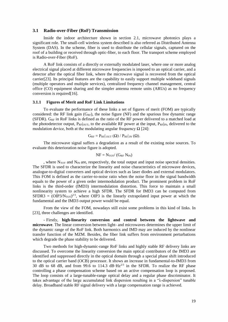
From the view of the FOM, nowadays still exist some problems in this kind of links. In
[23], three challenges are identified.
- Firstly, high-linearity conversion and control between the lightwave and
microwave. The linear conversion between light- and microwaves determines the upper limit of
the dynamic range of the RoF link. Both harmonics and IMD may are induced by the nonlinear
transfer function of the MZM. Besides, the fiber link suffers from environment perturbations
which degrade the phase stability to be delivered.
Two methods for high-dynamic-range RoF links and highly stable RF delivery links are
discussed. To overcome the linearity conversion the main optical contributors of the IMD3 are
identified and suppressed directly in the optical domain through a special phase shift introduced
to the optical carrier band (OCB) processor. It shows an increase in fundamental-to-IMD3 from
30 dB to 68 dB, and from 99.6 to 114.3 dB·Hz2/3 in the SFDR. To realize the RF phase
controlling a phase compensation scheme based on an active compensation loop is proposed.
The loop consists of a large-tunable-range optical delay and a regular phase discriminator. It
takes advantage of the large accumulated link dispersion resulting in a “λ-dispersion” tunable
delay. Broadband stable RF signal delivery with a large compensation range is achieved.

20
- Secondly, fine processing and handling of broadband microwave signals. The
challenge is to combine the broadband processing capability of photonics and the fine-
resolutions processing capability of electronics. An optical frequency comb (OFC) bridges the
gap between the broadband optical and the precise microwave in a single step. Two methods to
real-time, high-resolution monitoring of the RF spectrum and a scheme for multiband
microwave frequency conversion are introduced.
- Thirdly, efficient utilization and dynamic management of the resources in the DAS.
In some DAS applications, a single set of base-station facilities in the center unit is connected to
multiple antenna units (RAUs) to extend the indoor coverage of one base station and to share
the bandwidth resource. In 5G, this application will be employed to meet the high-rates and low
latency requirements with small-cells covering indoor spaces. In the paper, the performance of
the existing IEEE 802.11 MAC protocols, point coordination function (PCF) and distributed
coordination function (DCF), in simulcast WLAN RoF DASs is investigated. The adaptive PCF
is a promising mechanism in terms of the overall throughput and fairness among RAUs.
3.1.2 RoF role in Virtualized RAN
In [15], the cloud radio access system technology for the virtualized RAN (vRAN)
proposed for the 5G architecture is introduced. The main idea is to realize the mobile
backhaul/fronthaul of small-cells in outdoor environment via RoF as in the indoor environment.
C-RAN simplifies the ARUs by shifting MAC layer functions and baseband signal processing
to the central office (CO) or Baseband units (BBU) and the small-cells backhaul is
accomplished transmitting digital I/Q samples. This requires very high throughput and total
capacity of backhaul networks. Moreover, the separation between MAC and PHY layers require
an intensive control of latency and jitter in the CPRI.
In the vRAN case the ARU’s function is simpler by shifting DAC/ADC and RF frontend
functions to the BBU. In ARUs only remain O/E-E/O conversion and RF antennas. RF signals
are generated at BBU and transmitted to ARUs through fiber-optic backhaul by means of RoF.
It allows more cost-effective and scalable small-cell backhaul; infrastructure sharing by multiple
operators, multiple services and multiple wireless techniques (e.g. MIMO) while maintaining
independent configurability through the centralized network management.
3.2 Indoor Frequency Up-Conversion RoF Link
Indoor architecture described in section 2.1 is composed by a central unit (HCC),
responsible for central control and management unit, and the RN and the RAPs. The gateway
functions are a key to well address all network functions. There are three main categories of
signal processing to be dealt with in the gateway: (1) converting baseband digital signals in
Optical Access Networks (OAN) to/from indoor RF signals, (2) converting IF data signals in
OAN to/from indoor RF signals and (3) transparent handovers of RF data signals from OAN
to/from indoor network without conversion.
To deal with the conversion needed in signal processing (1) and (2) three functions are
required in the gateway. First is the baseband DSP, dealt with signal modulation and other DSP
functions. Second is the frequency up-conversion, which up-converts baseband data onto mm-
wave carrier frequency. Third is indoor exchange (IE) functions, which allow data switching
and routing inside the indoor fiber networks. In [25] two frequency up-conversion techniques
are proposed to achieve flexible reach data delivery, convenient frequency up-conversion and
versatile indoor exchange.
In all-optical remote up-conversion (RUC) technique, both optical baseband data and
optical mm-wave frequency are sent to the gateway (GW) with up-conversion realized in a
remote site. The scheme is shown in Figure 6. Baseband (BB) data is modulated on a
wavelength in the CO and then delivered to a RN. In the GW, the wavelength is split into two
paths, one for the downlink and other for the reflected uplink. Optical signals are assigned to

21
different flats/rooms in a dynamic way. Time division multiplexing (TDM) is employed, so the
BB wavelength will be routed to different destinations in different time frames.
Figure 6. Operation principle of all-optical remote up-conversion and indoor exchange
The dynamic allocation is realized by turning on specified wavelengths. They are
multiplexed via an optical multiplexer (MUX-1) and modulated using a local MZM biased at its
null point with a 30 GHZ local oscillator (LO). The blank 60 GHz optical mm-wave generated
at determined wavelengths. After being multiplexed (MUX-2) with the BB wavelength, the
output is fed into a SOA. Cross Gain Modulation (XGM) process in the SOA modulates the BB
data to the 60 GHz mm-waves. The result is separated by a de-multiplexer (DEMUX) and
distributed to different apartments/rooms. The optical routing is realized by switching on one
specific local wavelength while switching off the others. The IE functionality is colorless for the
CO.
For the uplink to the CO the data from each apartment/room are detected and then
modulated via a reflective SOA. The downlink wavelength injected to RSOA is amplified and
reflected out of RSOA with data modulation. Therefore, the uplink wavelength is reused from
downlink wavelength with colorless operation.
Experimental results show that 5 Gb/s OOK data carried by a 60 GHz hybrid fiber
wireless channel over 102 km SMF is successfully delivered with a power penalty less than 1.1
dB. Routing and optical multi-casting are demonstrated as well.
In free-running laser-based optical heterodyne technique (OH) the baseband data is
modulated on one wavelength and the other wavelength is used for optical beating to up-convert
the baseband data. No electrical local oscillator is involved. The diagram of the proposed system
is shown in Figure 7.
The baseband data of users are delivered from the CO to the GW of a densely-populated
region. At the GW are located all the functions except for frequency up-conversion. After
baseband processing, the processed signals are modulated onto different wavelengths, assigned
for the respective destinations. Inside the HCC, a set of arrived wavelengths (λ-3, λ-4) pass
through an optical circulator (Cir1) and coupled with the optical local oscillator signals (λ-3b, λ-
4b) via an optical coupler. The optical local oscillator signals are generated with two tunable
lasers. The coupled optical signals pairs travel toward the second circulator (Cir2). Due to the
fiber transmission induced polarization rotation, crosstalk occurs (OH process). The optical
signals are delivered to different rooms using a wavelength de-multiplexer (DEMUX).
This architecture is scalable and all wavelengths can be used since there are dedicated
optical fiber connections from each HCC to the GW. By tuning the wavelength of λ-3b and λ-
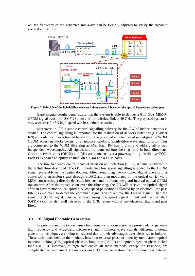
22
4b, the frequency of the generated mm-wave can be flexibly adjusted to satisfy the dynamic
spectral allocations.
Figure 7. Principle of the hybrid fibre wireless indoor network based on the optical heterodyne techniques
Experimental results demonstrate that the system is able to deliver a 61.3 Gb/s MIMO-
OFDM signal over 1 km SMF-28 fiber and 1 m wireless link at 40 GHz. The proposed system is
very attractive for 5G high-speed wireless indoor scenarios.
Moreover, in [25] a simple control signalling delivery for the GW of indoor networks is
studied. The control signalling is important for the realization of network functions (e.g. adapt
RN) and only occupies a limited bandwidth. The proposed architecture of reconfigurable WDM
OFDM access networks consist of a ring-tree topology. Single-fibre wavelength division trees
are connected to the WDM fibre ring at RNs. Each RN has to drop and add signals at two
independent wavelengths. All signals can be launched into the ring fibre in both directions.
Optical network units (ONUs) and RNs are connected via a power splitting distributive PON.
Each PON shares an optical channel on a TDM and a FDM basis.
The low frequency control channel insertion and detection (LFID) scheme is utilized in
the architecture described. The OOK modulated low speed signalling is added to the OFDM
signal, preferably in the digital domain. After combining, the combined digital waveform is
converted to an analog signal through a DAC and then modulated on the optical carrier via a
MZM constructing a directly detected, low cost and no frequency guard interval optical OFDM
transmitter. After the transmission over the fibre ring, the RN will receive the optical signal
after an asymmetric optical splitter. A low speed photodiode followed by an electrical low-pass
filter is employed to detect the combined signal and to remove the OFDM signal. Then the
signalling (OOK signal) can be retrieved using low speed logical circuit and the user data
(OFDM) can be also well retrieved in the ONU, even without any electrical high-band pass
filter.
3.3 RF Signal Photonic Generation
In previous section two schemes for frequency up-conversion are presented. To generate
high-frequency and wide-band microwave and millimeter-wave signals, different photonic
generation techniques are being considered due to their advantages over electrical techniques.
These techniques include the methods based on external phase or intensity modulators, optical
injection locking (OIL), optical phase-locking loop (OPLL) and optical injection phase-locked
loop (OIPLL). However, at high frequencies all these methods, except the first one, are
complicated to implement and/or expensive. Optical generation methods based on external
23
modulation are of great interest thanks to the wide frequency range and excellent stability of the
system. Since the most interesting mm-Wave frequencies for 5G indoor are in the range from 40
to 71 GHz, it would be relevant to achieve a tunable generation system able to produce mm-
wave signals in this range.
Four different generation techniques based on external modulation are introduced.
3.3.1 Triangular-shaped microwave pulses generation based on SBS
In [26], a triangular-shaped microwave pulse generator based on the external modulation
of a CW light wave is proposed. Triangular waveform has only odd-order harmonics. Therefore,
a MZM biased at the minimum-transmission-point (MITP) is used to generate only odd-order
optical sidebands.
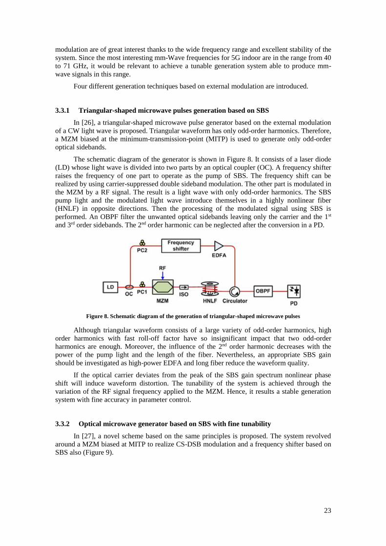
The schematic diagram of the generator is shown in Figure 8. It consists of a laser diode
(LD) whose light wave is divided into two parts by an optical coupler (OC). A frequency shifter
raises the frequency of one part to operate as the pump of SBS. The frequency shift can be
realized by using carrier-suppressed double sideband modulation. The other part is modulated in
the MZM by a RF signal. The result is a light wave with only odd-order harmonics. The SBS
pump light and the modulated light wave introduce themselves in a highly nonlinear fiber
(HNLF) in opposite directions. Then the processing of the modulated signal using SBS is
performed. An OBPF filter the unwanted optical sidebands leaving only the carrier and the 1st
and 3rd order sidebands. The 2nd order harmonic can be neglected after the conversion in a PD.
Figure 8. Schematic diagram of the generation of triangular-shaped microwave pulses
Although triangular waveform consists of a large variety of odd-order harmonics, high
order harmonics with fast roll-off factor have so insignificant impact that two odd-order
harmonics are enough. Moreover, the influence of the 2nd order harmonic decreases with the
power of the pump light and the length of the fiber. Nevertheless, an appropriate SBS gain
should be investigated as high-power EDFA and long fiber reduce the waveform quality.
If the optical carrier deviates from the peak of the SBS gain spectrum nonlinear phase
shift will induce waveform distortion. The tunability of the system is achieved through the
variation of the RF signal frequency applied to the MZM. Hence, it results a stable generation
system with fine accuracy in parameter control.
3.3.2 Optical microwave generator based on SBS with fine tunability
In [27], a novel scheme based on the same principles is proposed. The system revolved
around a MZM biased at MITP to realize CS-DSB modulation and a frequency shifter based on
SBS also (Figure 9).
24
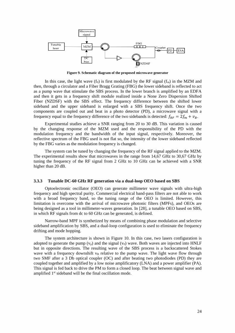
Figure 9. Schematic diagram of the proposed microwave generator
In this case, the light wave (f0) is first modulated by the RF signal (fm) in the MZM and
then, through a circulator and a Fiber Bragg Grating (FBG) the lower sideband is reflected to act
as a pump wave that stimulate the SBS process. In the lower branch is amplified by an EDFA
and then it gets in a frequency shift module realized inside a None Zero Dispersion Shifted
Fiber (NZDSF) with the SBS effect. The frequency difference between the shifted lower
sideband and the upper sideband is enlarged with a SBS frequency shift. Once the two
components are coupled out and beat in a photo detector (PD), a microwave signal with a
frequency equal to the frequency difference of the two sidebands is detected: 𝑓𝑅𝐹 = 2𝑓𝑚 + 𝑣𝐵.
Experimental studies achieve a SNR ranging from 20 to 30 dB. This variation is caused
by the changing response of the MZM used and the responsibility of the PD with the
modulation frequency and the bandwidth of the input signal, respectively. Moreover, the
reflective spectrum of the FBG used is not flat so, the intensity of the lower sideband reflected
by the FBG varies as the modulation frequency is changed.
The system can be tuned by changing the frequency of the RF signal applied to the MZM.
The experimental results show that microwaves in the range from 14,67 GHz to 30,67 GHz by
tuning the frequency of the RF signal from 2 GHz to 10 GHz can be achieved with a SNR
higher than 20 dB.
3.3.3 Tunable DC-60 GHz RF generation via a dual-loop OEO based on SBS
Optoelectronic oscillator (OEO) can generate millimeter wave signals with ultra-high
frequency and high spectral purity. Commercial electrical band-pass filters are not able to work
with a broad frequency band, so the tuning range of the OEO is limited. However, this
limitation is overcome with the arrival of microwave photonic filters (MPFs), and OEOs are
being designed as a tool in millimeter-waves generation. In [28], a tunable OEO based on SBS,
in which RF signals from dc to 60 GHz can be generated, is defined.
Narrow-band MPF is synthetized by means of combining phase modulation and selective
sideband amplification by SBS, and a dual-loop configuration is used to eliminate the frequency
drifting and mode hopping.
The system architecture is shown in Figure 10. In this case, two lasers configuration is
adopted to generate the pump (vp) and the signal (v0) wave. Both waves are injected into HNLF
but in opposite directions. The resulting wave of the SBS process is a backscattered Stokes
wave with a frequency downshift vB relative to the pump wave. The light wave flow through
two SMF after a 3 Db optical coupler (OC) and after beating two photodiodes (PD) they are
coupled together and amplified by a low noise amplificatory (LNA) and a power amplifier (PA).
This signal is fed back to drive the PM to form a closed loop. The beat between signal wave and
amplified 1st sideband will be the final oscillation mode.

25
Figure 10. Schematic diagram of the proposed dual-loop OEO based on SBS
The oscillation frequency adjusts to: 𝑣𝑜𝑠𝑐 = |𝑣0 − 𝑣𝑝 + 𝑣𝐵|. Therefore, by tuning the
wavelength of pump laser, the oscillation frequency changes. The frequency tunability range is
determined by the frequency response of the optoelectronic components in OEO’s loop.
Besides, the tuning step is limited by the wavelength tuning step of the pump laser.
3.3.4 39-GHz millimeter-wave carrier generation in dual-mode colorless laser diode
In [29], a 39 GHz mm-wave carrier generator is developed. The system is supported by a
null biased MZM for CCS-DSB modulation and dual-mode injection-locking of a directly
encoded colorless laser diode.
Figure 11. Experimental setup of CCS-DSB or dual-DFBLDs injection-locked slave colourless laser diode
The schematic diagram proposed is shown in Figure 11. The CCS-DSB master of the
injection-locking is generated by modulating a CW light from a DFB laser diode (DFBLD) with
a null-point biased MZM. After amplifying the modulated signal and filtering its ASE noise
with an optical bandpass filter, the final dual-mode master is seeded into the slave (colorless
laser diode) through an optical circulator. The electrical data to be delivered is pre-amplified
and its DC-level is offset by a bias tee for directly modulating the colorless laser diode. After a
25-km SMF transmission the data is received by a photodetector (PD), converted back to
electrical data and amplified by an electrical amplifier. If a localized wireless mm-wave access
link is the aim of the carrier generated a high-speed PD is employed with two high gain mm-
wave amplifiers. Then the mm-wave carrier is frequency down-converted to the baseband with a
4.875 GHz local oscillation frequency.
The performance of the proposed system is analyzed if CCA-DSB modulation or dual-
DFBLDs configuration is employed. As the central carrier of the master and the side-modes of
the injection-locked colorless laser diode can be suppressed in CCA-DSB (central carrier added
– DSB) because they will not be resonantly amplified, CCS-DSB represents a better option.
After the 25-km SMF, the residual central carrier and the FWM modes deteriorate the
transmission performance in the CCS-DSB case. However, the photonic mixed mm-wave
carrier in dual-DFBLDs is unstable in frequency domain because of the wavelength instability
of 2 DFBLDs. Consequently, the CCS-DSB modulation is the most appropriate.
26
3.4 Optical Conformation
Massive MIMO is supposed to be a key technology in 5G performance. At mm-wave, the
system is less interference limited, however the higher path loss requires coverage enhancing
solutions. With regards to compensate the path loss, employing beamforming capable
directional antennas is the industry proposal.
Beamforming is a technique to focus and steer the radio signal beam (or signal power) to
the desired directions. Instead of transmitting in all directions, antennas confine signal power in
a particular direction of interest. This is truly important in the indoor scenario and architecture
described, as it helps to provide the desired wider area coverage by dynamically steering the
beam to the user devices inside the cell coverage area. Moreover, it can reduce the energy
consumption in the transmitter as it requires less transmission power to achieve same amount of
signal power at receiver.
By focussing in certain directions, the interferences are limited to small fractions of the
entire space around a transmitter improving the radio environment. It will also be useful at
lower frequencies to extend coverage and to provide higher data rates in sparse deployments for
example.
Because of their fast steering and compactness, phased array antennas (PAAs) seems to
be the most attractive beamsteering method at the mm-wave band. The technique is based on the
control of the phases/amplitudes of the radio signals radiated by the antenna elements to induce
constructive combination at desired directions and destructive ones at other directions.
Given N elements of a PAA, the antenna gain and SNR improvement can be achieved by
a factor of N. The PAA elements should be separated at least half the wavelength of the radio
signal. Therefore, the small wavelength at mmWave frequencies implies that the antenna
elements will be closely spaced, facilitating the compactness of a large-size PAA.
Traditionally, beamforming is realized in electronic circuits. Samsung has recently
proposed and demonstrated a mm-wave communication empowered by beam steering based on
electronic devices[30]. The use of phase shifters limits the operational bandwidth of a
conventional PAA. True Time Delay (TTD) is the basis for broadband beam steering but
electronic integrated circuits suffer from high loss at high frequencies. The emerging technique
is TTD beamforming by means of optical circuits (OTTD) to benefit from their low loss and
broad bandwidth.
The indoor architecture envisioned in section 2.1 makes beamforming different from the
traditional beamforming because of the remote baseband processing. The RoF benefits from
OTTD since no additional E/O-O/E conversion is necessary. Besides, it keeps the RAPs simple,
a fundamental feature in RoF architectures. In the architecture description is mentioned that the
HCC must remotely control, among other aspects, beam steering. OTTD does it by changing the
optical wavelengths, and it avoids extra control signal requiring strict synchronization.
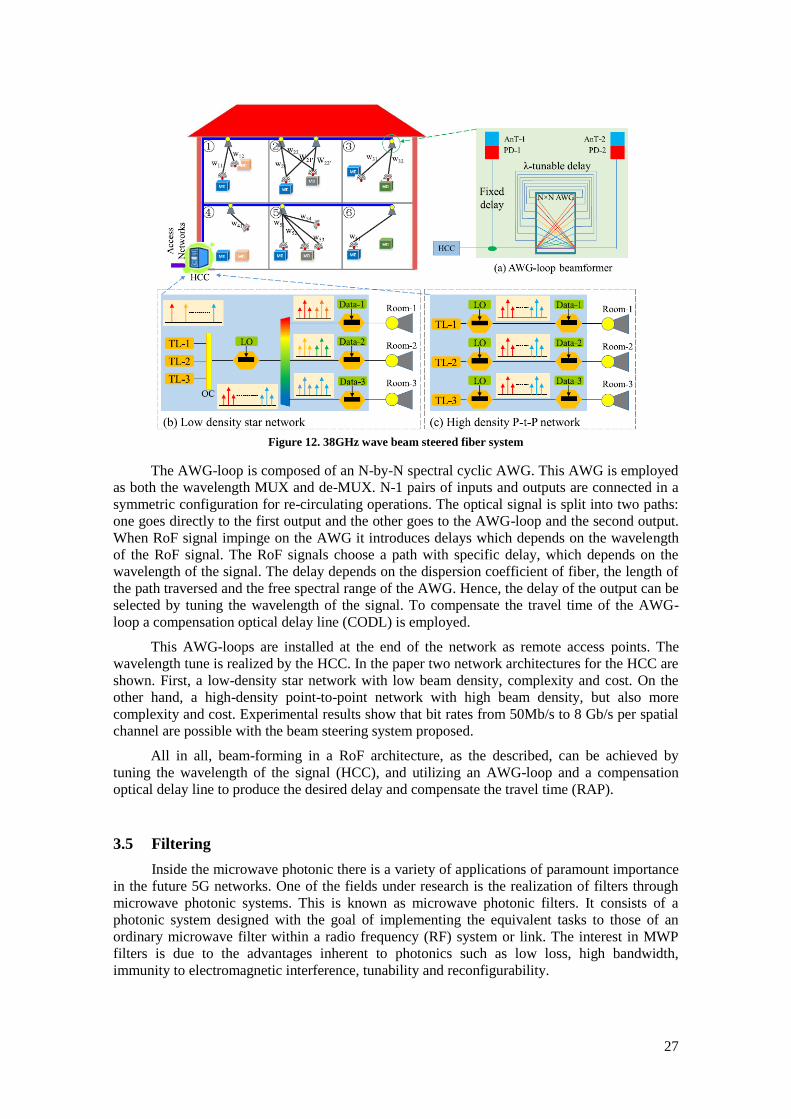
In [31], a 38 GHz beam steered millimeter-wave system based on OTTD and two
architectures for such beam-steering are proposed. A remotely tunable integrated optical tunable
delay line (OTDL) based on an arrayed waveguide grating feedback loop (AWG-loop) is
employed. Figure 12 illustrates the proposed system.
27
Figure 12. 38GHz wave beam steered fiber system
The AWG-loop is composed of an N-by-N spectral cyclic AWG. This AWG is employed
as both the wavelength MUX and de-MUX. N-1 pairs of inputs and outputs are connected in a
symmetric configuration for re-circulating operations. The optical signal is split into two paths:
one goes directly to the first output and the other goes to the AWG-loop and the second output.
When RoF signal impinge on the AWG it introduces delays which depends on the wavelength
of the RoF signal. The RoF signals choose a path with specific delay, which depends on the
wavelength of the signal. The delay depends on the dispersion coefficient of fiber, the length of
the path traversed and the free spectral range of the AWG. Hence, the delay of the output can be
selected by tuning the wavelength of the signal. To compensate the travel time of the AWG-
loop a compensation optical delay line (CODL) is employed.
This AWG-loops are installed at the end of the network as remote access points. The
wavelength tune is realized by the HCC. In the paper two network architectures for the HCC are
shown. First, a low-density star network with low beam density, complexity and cost. On the
other hand, a high-density point-to-point network with high beam density, but also more
complexity and cost. Experimental results show that bit rates from 50Mb/s to 8 Gb/s per spatial
channel are possible with the beam steering system proposed.
All in all, beam-forming in a RoF architecture, as the described, can be achieved by
tuning the wavelength of the signal (HCC), and utilizing an AWG-loop and a compensation
optical delay line to produce the desired delay and compensate the travel time (RAP).
3.5 Filtering
Inside the microwave photonic there is a variety of applications of paramount importance
in the future 5G networks. One of the fields under research is the realization of filters through
microwave photonic systems. This is known as microwave photonic filters. It consists of a
photonic system designed with the goal of implementing the equivalent tasks to those of an
ordinary microwave filter within a radio frequency (RF) system or link. The interest in MWP
filters is due to the advantages inherent to photonics such as low loss, high bandwidth,
immunity to electromagnetic interference, tunability and reconfigurability.

28
Figure 13. General reference layout of a microwave photonic filter
Figure 13 illustrates a general reference layout of a MWP filter. The RF to optical
conversion is realized by directly (or externally) modulating a single continuos wave (CW)
source or a CW source array. The input RF signal is carried by the optical carrier and the
resulting signal is fed to a photonic circuit that samples the signal in the time domain, weights
the samples and combines them using optical delay lines and other photonic elements [32]. The
output optical field is optically RF converted. The lower part of Figure 13 shows an equivalent
black-box representation of the aimed performance of the MWP filter. The only signal linearity
is that relating the input and output optical fields to the optical subsystem by virtue of the
linearity of Maxwell’s equations. According to the number of samples N in the impulse
response sequence, the filter can be classified as a finite impulse response (FIR) if N < 8 or an
infinite impulse response if N > 8.
The transfer function is spectrally periodic with a period of 2π/T in angular frequency
units or 1/T in frequency unit. Therefore, the spectrum is periodic. The period mentioned is
known as the filter free spectral range (FSR).
In the paper two kinds of MWP filters and possible implementations are introduced. On
the one hand, single-source microwave photonic filters are characterized by the use of only one
optical source to feed the filter. The source output electric field is modulated by the RF input
signal and the different filter samples are implemented by means of delayed and windowed
replicas of the RF-modulated optical carrier. Two possible implementations of a FIR and an IIR
SSMPF are shown. On the other hand, in multiple-source microwave photonic filters the RF
input signal optically combines and modulates the output of an array of optical CW sources.
The source array can be implemented through an array of independent lasers or by slicing the
output of a broadband source by means of a periodic optical filter. Each source implements a
filter sample that is selectively delayed by employing a dispersive line implemented either by a
fiber coil or by a linearly chirped fiber Bragg grating (LCFBG). The dispersive delay element is
chosen such that the differential group delay experienced by adjacent wavelengths of the source
array is T.
However, MWP filters must still overcome potential limitations either in the optical and
the electrical domain. Within the optical domain, it is found the spectral periodicity, which
limits the bandwidth of the RF signal to be processed to a fraction of the FSR in order to avoid
spectral overlapping; the positive coefficients, because it limits the range of transfer functions
that can be implemented; fiber nonlinearities such as self-phase modulation (SPM), cross-phase
29
modulation (XPM), four-wave mixing (FWM), etc; polarization effects; limited spectral period;
reconfigurability and tunability. In the electrical domain the total RF gain, the noise figure and
the harmonic and intermodulation distortion are the limitations to overcome.
There is a wide range of applications inside 5G networks where MWP filters can be of
interest. In the way to increase the capacity, RoF systems enable to centralize the RF signal
processing functions in a shared location (headend) simplifying the remote antenna units
(RAUs). The processing at the headend involves a prior frequency down-conversion, ADC, and
baseband processing using a DSP. The down-conversion can be eliminated or divided into two
steps if a MWP filters placed prior to optical detection.
Besides, they can help to suppression the noise and to mitigate the channel interference,
very important in a high-density environment. Moreover, they can also be employed in the field
of true-time delay beam steering of antenna arrays. The feeder network of an array of N
antennas is essentially equivalent to an N-tap MWP tunable FIR filter where the basic filter
delay T can be altered. The only difference is that each filter sample is detected by a different
optical receiver that is placed before each antenna unit in the array.

30
Chapter 4. System Designs, Simulations and Results
As it has been shown, there are many applications for Microwave Photonics in 5G indoor
environment. This work revolves around the generation of mm-wave signals through
Microwave photonics techniques.
Four different techniques are presented, one of this is focused in generate Triangular-
Shaped pulses instead of generating high-frequencies signals through lower-frequencies
oscillators. All of them are based on the use of one Mach-Zehnder modulator to generate the
mm-wave signal; and the Stimulated Brillouin Scattering (SBS) will play an important role in
some of the techniques.
To simulate the systems and check their performance VPI photonics software has been
chosen as the simulation platform software.
The chapter has been divided into the next sections:
• Section 4.1 describes the simulation platform software
• Section 4.2 explains a transmission scheme which does not make use of MWP
techniques to transmit the information
• Section 4.3 shows an alternative design to transmit the information by employing
MWP techniques
• Section 4.4 shows the simulation process of the optical microwave generator
based on SBS with fine tunability introduced in section 3.3
• Section 4.5 shows the simulation process of the triangular-shaped microwave
pulses generator introduced in section 3.3
• Section 4.6 introduces a proposed mm-wave generator based on two lasers with
enhanced flexibility

31
4.1 Description of the Software
As already noted, VPI photonics is the simulation platform software on which the
simulations realized are based.
VPI photonics is a professional simulation software which allows to end-to-end photonic
design automation comprising design, analysis and optimization of components, systems and
networks. It supports requirements of active/passive integrated photonics and fiber optics
applications, optical transmission system and network applications, as well as cost-optimized
equipment configuration.
VPI photonics requires the following minimum configuration:
• 1 GHz or faster 64-bit (x64) processor
• 2 GB RAM
• 2 GB of free hard disk space for software installation process, 1 GB additionally
recommended for file storage
• XGA monitor with 1024x768 pixels minimum display resolution
• DirectX 9 graphics device with WDDM 1.0 or higher driver
• For GPU-assisted computations NVIDIA video adapter with compute capability
greater than or equal to version 1.3 and double-precision support is required
• DVD-ROM drive
• Windows 7, Windows 8.1 or Windows 10 Enterprise
The system is based on the union of different modules which can represent components,
converser units, analysers, etc. All the systems simulated in this thesis lean on three modules:
Mach-Zehnder modulator, a DFB continuous-wave laser and a photodiode. These three modules
remain unchanged in all the systems.
The Mach-Zehnder modulator module employed has the following parameters:
Figure 14. Parameters MZM module

32
With the previous characteristics, its normalized transfer function is as depicted in Figure
15.
Figure 15. MZM transfer function
In this way, the minimum-transmission-point (MITP) or null-point is at 2.5 V and the
quadrature-point at 3.75 V. These are the main biasing points employed, the first for double-
sideband carrier suppressed modulation (mm-wave generation) and the second for data
modulation.
On the other hand, the laser is a DFB continuous-wave laser centred in 193.1 THz, with
an average power of 10 mW and 10 MHz of linewidth.
Figure 16. Laser parameters
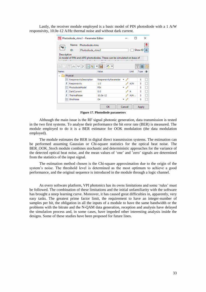
33
Lastly, the receiver module employed is a basic model of PIN photodiode with a 1 A/W
responsivity, 10.0e-12 A/Hz thermal noise and without dark current.
Figure 17. Photodiode parameters
Although the main issue is the RF signal photonic generation, data transmission is tested
in the two first systems. To analyse their performance the bit error rate (BER) is measured. The
module employed to do it is a BER estimator for OOK modulation (the data modulation
employed).
The module estimates the BER in digital direct transmission systems. The estimation can
be performed assuming Gaussian or Chi-square statistics for the optical beat noise. The
BER_OOK_Stoch module combines stochastic and deterministic approaches for the variance of
the detected optical beat noise, and the mean values of ‘one’ and ’zero’ signals are determined
from the statistics of the input signal.
The estimation method chosen is the Chi-square approximation due to the origin of the
system’s noise. The threshold level is determined as the most optimum to achieve a good
performance, and the original sequence is introduced in the module through a logic channel.
As every software platform, VPI photonics has its owns limitations and some ‘rules’ must
be followed. The combination of these limitations and the initial unfamiliarity with the software
has brought a steep learning curve. Moreover, it has caused great difficulties in, apparently, very
easy tasks. The greatest prime factor limit, the requirement to have an integer-number of
samples per bit, the obligation in all the inputs of a module to have the same bandwidth or the
problems with the bitrate and the N-QAM data generation, reception and analysis have delayed
the simulation process and, in some cases, have impeded other interesting analysis inside the
designs. Some of these studies have been proposed for future lines.

34
4.2 Conventional 10 Gbps NRZ OOK RoF Link
In order to compare the different systems performance, a RF transmission scheme is
presented. In [33] a 24 Gb/s CAP-64QAM RoF system over 40-GHz transmission is proposed
and demonstrated. The transmission scheme indicated is based on this system. With the
intention of making easier the comparison the system is simplified. In this way, the data
transmitted will be 10 Gbps NRZ OOK and the wireless transmission will not be included.
Figure 18. Schematic diagram of the proposed transmission system
Figure 18 shows the RoF signal modulation and mm-wave generation architecture.
Optical Carrier Suppression (OCS) method is employed to generate the mm-wave as the system
is easy to configure and it has a good performance. This method is the fundamental pillar of all
the system, and is the main advantage of MWP techniques for mm-wave generation. The
process works as follow: when biasing the MZM at the null point, the light source is modulated
so that the carrier is almost suppressed and double sidebands appear at the frequency (fs) which
drives the MZM, so the separation between them is the double of that frequency. When the
signal beats the photodiode a carrier at 2fs is generated.
Besides the MZM for mm-wave generation, other MZM is used to modulate the signal. A
continuous-wavelength (CW) light is the optical source and it is split into two arms in the I/Q
modulator. This modulator consists of two MZMs placed in parallel, and a phase shifter in the
lower arm. The upper arm is for the NRZ OOK modulation, while the other is for the mm-wave
generation through OCS. For the OCS the MZM is biased at the null-point and the MZM is
driven by a fs RF signal. After joining both signals, the resulting signal is filtered with an optical
band-pass filter (OBPF) that will keep the base-band signal and the first-order tone. The other
undesired tones are cut off, so the frequency spacing between the base-band signal and the first-
order tone is fs. In this way, when the signal beats the photodiode, the mm-wave is generated at
fs, ready to be wireless transmitted. As indicated in the paper, the laser linewidth has no obvious
impact on the results as the outputs of the two arms are from the same light source and only
intensity modulation is used in each arm. To analyse the system’s BER, the signal is down-
converted to base-band.

35
To simulate with VPI, an experimental scheme of 10 Gbps NRZ OOK RoF system over
2.5-km SSMF 30 GHz transmission is shown in Figure 19.
Figure 19. Schematic of a 10 Gbps NRZ OOK RoF system over 2.5-hm SSMF 30 GHz transmission
The laser source and the MZMs are the described in the beginning of the chapter. The I/Q
modulator is available with two parallel MZMs. The upper arm is driven by the 10 Gbps NRZ
OOK signal. It is generated via a binary sequence mapped to the 2 level OOK with a NRZ
module. The bandwidth of the signal is 20 GHz. As the signal bandwidth and the optical source
bandwidth are different a resample is necessary before the MZM. To modulate the signal, the
MZM is biased at the quadrature point. As it has been said, the MZM in the lower arm operates
in OCS condition to mm-wave generation. Then, the MZM is biased at the null point (2.5 V)
and driven by a 30-GHz RF signal. The output of the MZM suffers a phase shift and both arms
are coupled.
Figure 20, Figure 21 and Figure 22 show the optical spectrum of the output of lower arm
MZM with mm-wave tones, the output of upper arm MZM with base-band signal and their
union. From Figure 20 we can see a carrier suppression result with more than 25-dB first-tone to
carrier power ratio.
Figure 20. Optical spectrum at b)
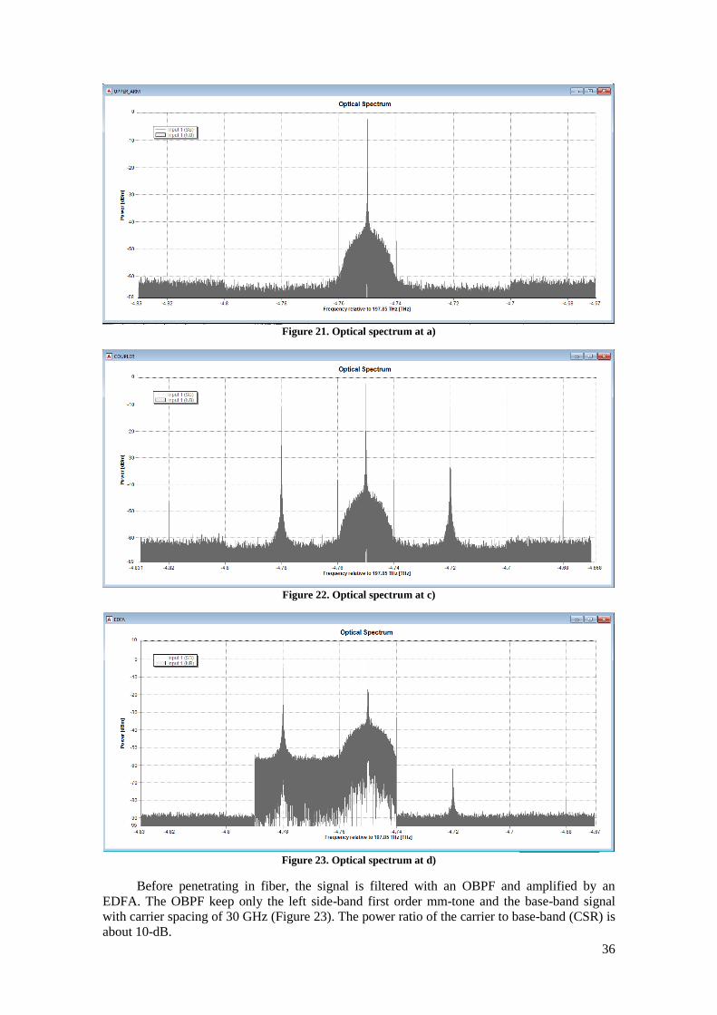
36
Figure 21. Optical spectrum at a)
Figure 22. Optical spectrum at c)
Figure 23. Optical spectrum at d)
Before penetrating in fiber, the signal is filtered with an OBPF and amplified by an
EDFA. The OBPF keep only the left side-band first order mm-tone and the base-band signal
with carrier spacing of 30 GHz (Figure 23). The power ratio of the carrier to base-band (CSR) is
about 10-dB.

37
The EDFA is employed before the fiber to compensate the fiber loss. Once the signal is
amplified, it is launched into the 2.5-km SSMF, which has about 5 dB loss at 193.1 THz. Then,
the mm-wave signal is filtered again to reduce undesired components, as the ASE noise
introduced by the EDFA, and up-converted by the photodiode.
Figure 24. Electrical spectrum of the received 10 Gbps NRZ OOK mm-wave signal at 30 GHz
To compare the received signal with the transmitted ones, the signal is down converted to
base-band by multiplying with a sine function. Then a BER analysis is executed. Figure 25,
Figure 26, Figure 27 and Figure 28 show the optical spectrum of the down-converted signal, the
waveform of the received sequence, the waveform of the original sequence and the BER results
with 2 different speeds (5 and 10 Gbps). The results are very poor as the lowest BER level is 1e-
3 at 10 Gbps and 1.311e-5 at 5 Gbps with a measured receiver sensitivity of -25 dBm.
Figure 25. Electrical spectrum of the down-converted base-band 10 Gbps NRZ OOK signal
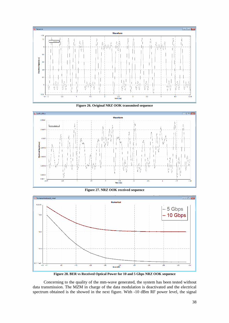
38
Figure 26. Original NRZ OOK transmited sequence
Figure 27. NRZ OOK received sequence
Figure 28. BER vs Received Optical Power for 10 and 5 Gbps NRZ OOK sequence
Concerning to the quality of the mm-wave generated, the system has been tested without
data transmission. The MZM in charge of the data modulation is deactivated and the electrical
spectrum obtained is the showed in the next figure. With -10 dBm RF power level, the signal
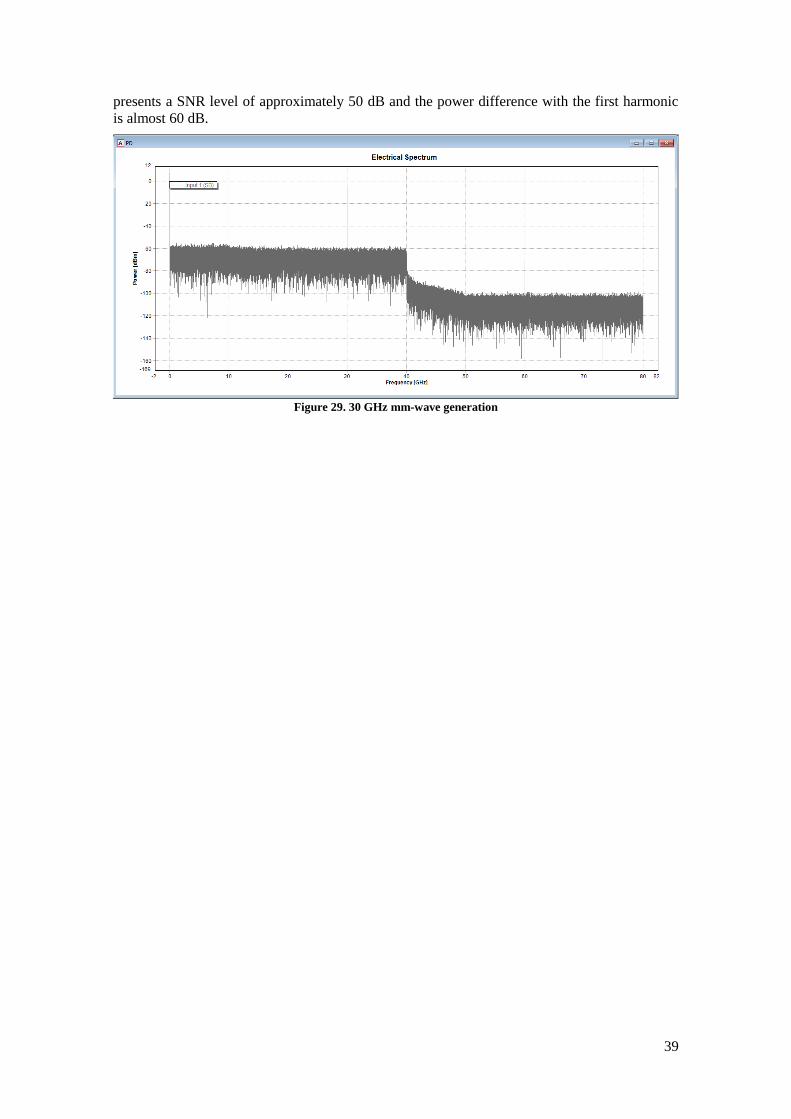
39
presents a SNR level of approximately 50 dB and the power difference with the first harmonic
is almost 60 dB.
Figure 29. 30 GHz mm-wave generation

40
4.3 Microwave Photonics based 10 Gbps NRZ OOK RoF Link
Now that the transmission design has been described it is the turn to present alternative
designs. The next design is the current most basic scheme to achieve mm-wave generation
through microwave photonic techniques, and it is based in the system proposed in [34]. The
most important contribution of this scheme in comparison with the previous design is the use of
oscillators with the half frequency. While in the preceding system it is necessary a fs oscillator
to transmit the data in a fs mm-wave signal, here the required oscillator frequency is the half to
transmit the same data at the same frequency.
Figure 30. Alternative schematic of a 10 Gbps NRZ OOK RoF system over 2.5-km SSMF 30 GHz
Figure 30 shows the configuration of a 30 GHz radio-over-fiber NRZ OOK link system.
In general, it consists of an optical carrier generation unit, a broadband data modulation, a fiber
link and an optical receiver. As the previous design, it needs two MZM, one for the mm-wave
generation and the other for the modulation, but they are not placed in parallel but in serial. The
process to obtain the mm-wave through the first MZM is the same as the transmission design:
3the light from the laser source is modulated into the MZM biased at null-point (Vpi) to
generate an optical double-sideband signal with suppressed carrier (DSB-SC). The MZM is
driven by a 15 GHz oscillator. The optical carrier suppression is approximately 26 dB (Figure
31).
Figure 31. Optical spectrum at a)
Via the second MZM the optical carrier is modulated with NRZ OOK data by biasing the
modulator to the quadrature point. A PRBS generator and a NRZ modulator produce the 10
Gbps and 20 GHz bandwidth signal. Figure 32 show the data modulated over the optical carrier.
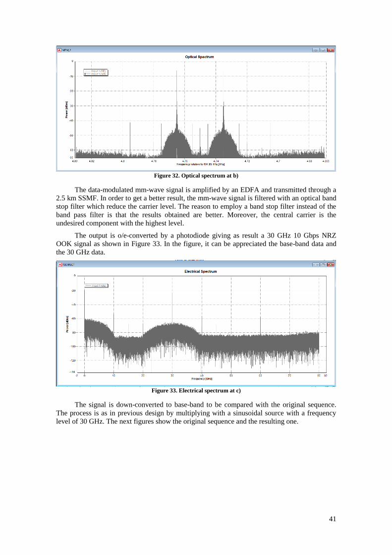
41
Figure 32. Optical spectrum at b)
The data-modulated mm-wave signal is amplified by an EDFA and transmitted through a
2.5 km SSMF. In order to get a better result, the mm-wave signal is filtered with an optical band
stop filter which reduce the carrier level. The reason to employ a band stop filter instead of the
band pass filter is that the results obtained are better. Moreover, the central carrier is the
undesired component with the highest level.
The output is o/e-converted by a photodiode giving as result a 30 GHz 10 Gbps NRZ
OOK signal as shown in Figure 33. In the figure, it can be appreciated the base-band data and
the 30 GHz data.
Figure 33. Electrical spectrum at c)
The signal is down-converted to base-band to be compared with the original sequence.
The process is as in previous design by multiplying with a sinusoidal source with a frequency
level of 30 GHz. The next figures show the original sequence and the resulting one.

42
Figure 34. Original NRZ OOK transmited sequence
Figure 35. NRZ OOK received sequence
In order to analyse the system performance and how some parameters affect it behaviour,
BER results versus receiver optical power are represented. The parameters studied are the data
bit rate (Figure 36) and the mm-wave signal frequency (Figure 37).
Figure 36. BER vs Received Optical Power for 10 and 5 Gbps at 30 GHz

43
Figure 37. BER vs Received Optical Power for 30 GHz and 40 GHz signal at 10 Gbps
The first graphic shows a clearly better performance when employing the half bit rate. A -
25 dBm receiver sensitivity achieves a BER level of about 1.7e-12 with 5 Gbps while 7.3e-7
with 10 Gbps. In the case of the frequency, the curve slopes are very similar. The lower BER
level (4e-8) at 40 GHz point a better performance when the sidebands separation is greater.
In order to analyze the mm-wave signal quality, the electrical spectrum of the carrier
generated without data modulation is depicted in Figure 38. The signal has a power of -10.63
dBm, it presents a SNR of 60 dB and the power difference with the harmonic is almost 30 dB.
Figure 38. Electrical spectrum 30 GHz mm-wave signal
Now that both designs have been broken down, is the turn to compare them. Focussing in
the data transmission, the MWP based design is significantly superior as the BER graphics
demonstrate while the carrier figures of merits are very similar.
Besides, the design needs slightly less equipment. However, is the oscillator difference
the most important aspect, as the feature and cost are extremely tied. The chance of utilizing an
oscillator which the half frequency, in microwave frequency band is an aspect to take into
account.
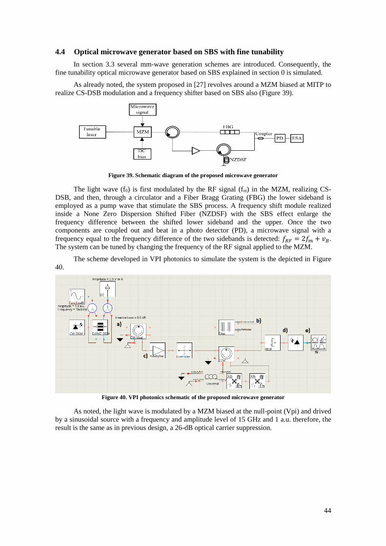
44
4.4 Optical microwave generator based on SBS with fine tunability
In section 3.3 several mm-wave generation schemes are introduced. Consequently, the
fine tunability optical microwave generator based on SBS explained in section 0 is simulated.
As already noted, the system proposed in [27] revolves around a MZM biased at MITP to
realize CS-DSB modulation and a frequency shifter based on SBS also (Figure 39).
Figure 39. Schematic diagram of the proposed microwave generator
The light wave (f0) is first modulated by the RF signal (fm) in the MZM, realizing CS-
DSB, and then, through a circulator and a Fiber Bragg Grating (FBG) the lower sideband is
employed as a pump wave that stimulate the SBS process. A frequency shift module realized
inside a None Zero Dispersion Shifted Fiber (NZDSF) with the SBS effect enlarge the
frequency difference between the shifted lower sideband and the upper. Once the two
components are coupled out and beat in a photo detector (PD), a microwave signal with a
frequency equal to the frequency difference of the two sidebands is detected: 𝑓𝑅𝐹 = 2𝑓𝑚 + 𝑣𝐵.
The system can be tuned by changing the frequency of the RF signal applied to the MZM.
The scheme developed in VPI photonics to simulate the system is the depicted in Figure
40.
Figure 40. VPI photonics schematic of the proposed microwave generator
As noted, the light wave is modulated by a MZM biased at the null-point (Vpi) and drived
by a sinusoidal source with a frequency and amplitude level of 15 GHz and 1 a.u. therefore, the
result is the same as in previous design, a 26-dB optical carrier suppression.

45
Figure 41. Optical spectrum at a)
The FBG filter handles the separation between the lower and the upper sideband. The first
one is reflected to the circulator and amplified by an EDFA before entering in the frequency
shift module.
The FBG frequency is set in 193.089 THz, the bandwidth is 50 GHz and the band
rejection is 40 dB. In Figure 42 the filter parameter configuration is showed as well as its
spectral response.
Figure 42. FBG filter parameters and characterization

46
Figure 43. Optical spectrum at b)
Figure 44. Optical spectrum at c)
The frequency shift module consists of a 10-km NZDSF. The SBS parameters are a 100-
MHz bandwidth and a Stokes shift of 11 GHz. VPI Photonics works with diverse kinds of
signals and it differentiates between Stokes signals and sampled band signal. So, a pair of
converters are necessary or they will not interact. In the optical coupler, the upper sideband and
the frequency shifted Stokes wave are coupled (Figure 45).
Figure 45. Optical spectrum at d)

47
The signal beats a photodiode and is o/e-converted. With a -38.72 dBm power, the mm-
wave presents an approximately 50-dB SNR. The power difference with the highest undesired
component is approximately 34 dB.
Figure 46. Electrical spectrum at e)
The system tunability has been tested with different driven frequencies and, as can be
seen in Figure 47, the performance is not affected by the selected frequency.
Figure 47. Electrical spectrum of 21 GHz, 31 GHz, 41 GHz, 51 GHz, 61 GHz and 71 GHz carriers
The process followed to test the tunability is the same as the realized in [27]. The
modulation frequency applied to the MZM is varied between 5 and 30 GHz with 5 GHz steps.
In the paper [27], is demonstrated that the central frequency of the system is given by:
𝑓𝑅𝐹 = 2𝑓𝑚 + 𝑣𝐵
, where vB is the SBS frequency shift and fm is the frequency applied to the MZM. The
Stokes frequency shift is 11 GHz in the design. According to the formula, the Stokes shift and
the oscillator frequencies employed, 21 GHz, 31 GHz, 41 GHz, 51 GHz, 61 GHz and 71 GHz
carriers are obtained. It should be mentioned that the FBG center frequency must also be varied
to be adjusted to the new sidebands separation.
In [27] the authors experimentally demonstrate the microwave generation with a SNR
higher than 20 dB in the range from 14.67 GHz to 30.67 GHz. The simulation realized in the
thesis also that SNR level and check the tunability between 21 GHz to 71 GHz.

48
4.5 Photonic generation of triangular-shaped microwave pulses using SBS-based
optical carrier processing
Due to it interest and their use in signal processing, the photonic generation of triangular-
shaped microwave pulses introduced in section 233.3.1 is also simulated.
Triangular-shaped mm-wave pulses are a waveform kind with only odd-order harmonics.
Therefore, a MZM biased at the minimum-transmission-point (MITP) is used to generate only
odd-order optical sidebands.
The schematic diagram of the generator proposed in [26] is shown in Figure 48.
Figure 48. Schematic diagram of a triangular-shaped microwave pulses generator
As it was said, it consists of a laser diode (LD) whose light wave is divided into two parts
by an optical coupler (OC). A frequency shifter raises the frequency of one part to operate as the
pump of SBS. The frequency shift can be realized by using carrier-suppressed double sideband
modulation. The other part is modulated in the MZM by a RF signal. The result is a light wave
with only odd-order harmonics. The SBS pump light and the modulated light wave introduce
themselves in a highly nonlinear fiber (HNLF) in opposite directions. Then the processing of the
modulated signal using SBS is performed. An OBPF filter the unwanted optical sidebands
leaving only the carrier and the 1st and 3rd order sidebands. The 2nd order harmonic can be
neglected after the conversion in a PD.
Although triangular waveform consists of a large variety of odd-order harmonics, high
order harmonics with fast roll-off factor have so insignificant impact that two odd-order
harmonics are enough.
The scheme utilized to simulate the system in VPI Photonics is the following:
Figure 49. VPI Photonics schematic for the proposed system
As in the other systems, the light source is modulated in a MZM biased at the null point
(Vpi). However, the frequency and amplitude level of the sinusoidal source that drives the
MZM are different. The frequency level is now 8 GHz and the amplitude is 2.5 a.u. to achieve
higher level harmonics. An amplitude of 1 a.u. gives very poor harmonics, very essential in this
case. Here, the carrier suppression rate is approximately 35 dB. The modulated signal is
amplified by an EDFA before entering in the 10-km HNLF.
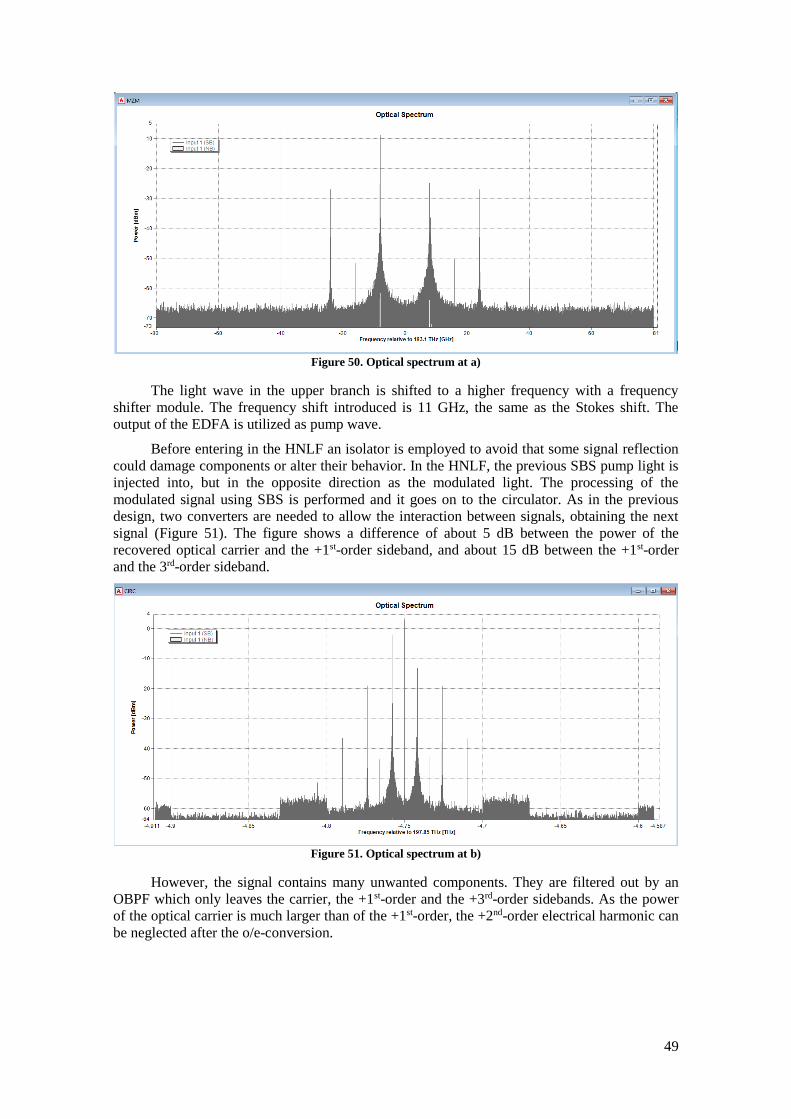
49
Figure 50. Optical spectrum at a)
The light wave in the upper branch is shifted to a higher frequency with a frequency
shifter module. The frequency shift introduced is 11 GHz, the same as the Stokes shift. The
output of the EDFA is utilized as pump wave.
Before entering in the HNLF an isolator is employed to avoid that some signal reflection
could damage components or alter their behavior. In the HNLF, the previous SBS pump light is
injected into, but in the opposite direction as the modulated light. The processing of the
modulated signal using SBS is performed and it goes on to the circulator. As in the previous
design, two converters are needed to allow the interaction between signals, obtaining the next
signal (Figure 51). The figure shows a difference of about 5 dB between the power of the
recovered optical carrier and the +1st-order sideband, and about 15 dB between the +1st-order
and the 3rd-order sideband.
Figure 51. Optical spectrum at b)
However, the signal contains many unwanted components. They are filtered out by an
OBPF which only leaves the carrier, the +1st-order and the +3rd-order sidebands. As the power
of the optical carrier is much larger than of the +1st-order, the +2nd-order electrical harmonic can
be neglected after the o/e-conversion.
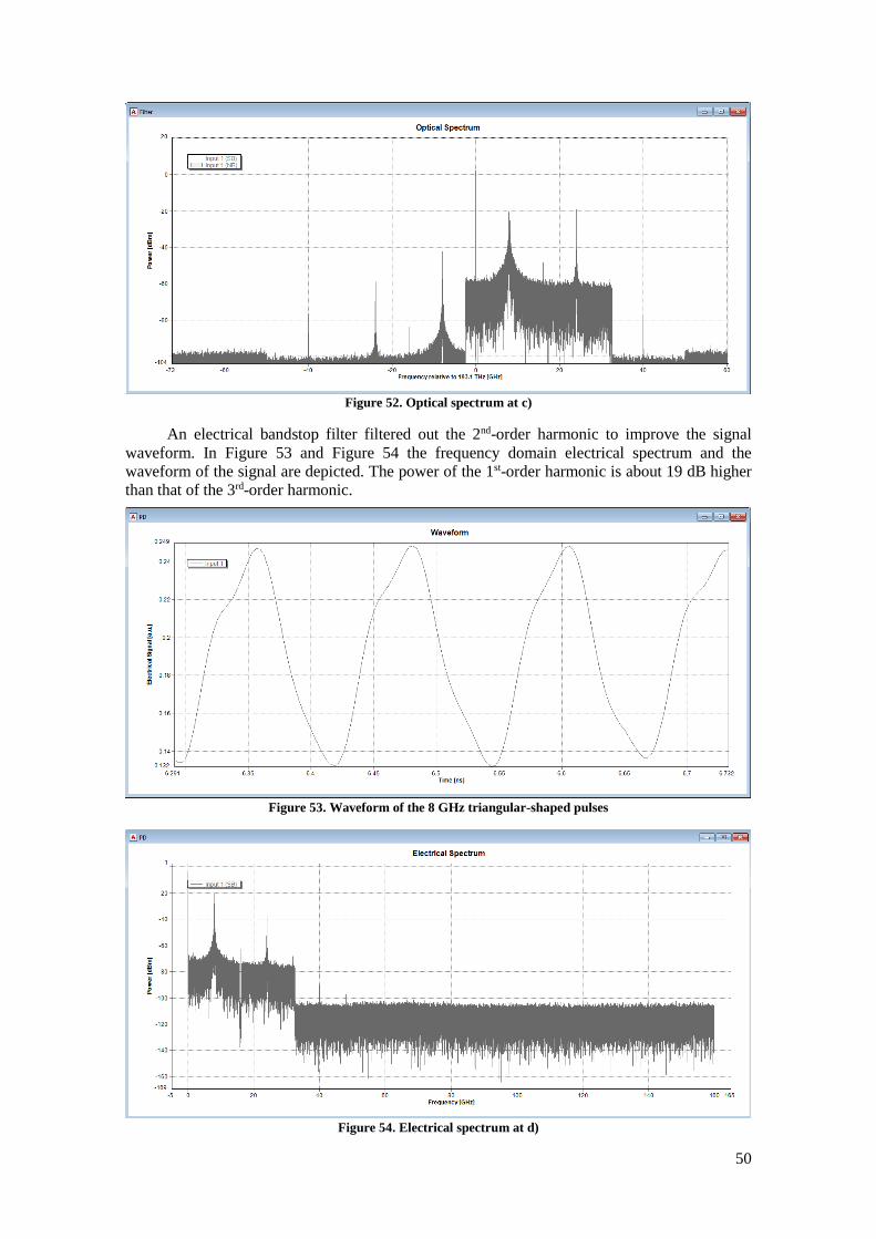
50
Figure 52. Optical spectrum at c)
An electrical bandstop filter filtered out the 2nd-order harmonic to improve the signal
waveform. In Figure 53 and Figure 54 the frequency domain electrical spectrum and the
waveform of the signal are depicted. The power of the 1st-order harmonic is about 19 dB higher
than that of the 3rd-order harmonic.
Figure 53. Waveform of the 8 GHz triangular-shaped pulses
Figure 54. Electrical spectrum at d)
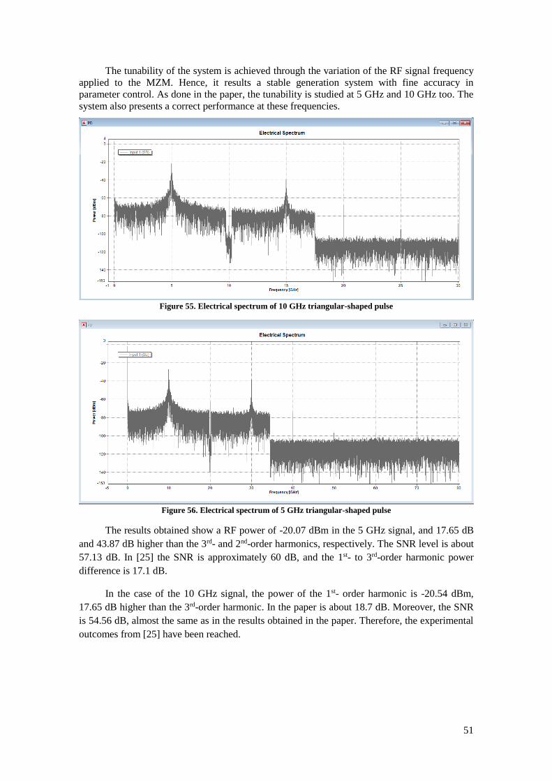
51
The tunability of the system is achieved through the variation of the RF signal frequency
applied to the MZM. Hence, it results a stable generation system with fine accuracy in
parameter control. As done in the paper, the tunability is studied at 5 GHz and 10 GHz too. The
system also presents a correct performance at these frequencies.
Figure 55. Electrical spectrum of 10 GHz triangular-shaped pulse
Figure 56. Electrical spectrum of 5 GHz triangular-shaped pulse
The results obtained show a RF power of -20.07 dBm in the 5 GHz signal, and 17.65 dB
and 43.87 dB higher than the 3rd- and 2nd-order harmonics, respectively. The SNR level is about
57.13 dB. In [25] the SNR is approximately 60 dB, and the 1st- to 3rd-order harmonic power
difference is 17.1 dB.
In the case of the 10 GHz signal, the power of the 1st- order harmonic is -20.54 dBm,
17.65 dB higher than the 3rd-order harmonic. In the paper is about 18.7 dB. Moreover, the SNR
is 54.56 dB, almost the same as in the results obtained in the paper. Therefore, the experimental
outcomes from [25] have been reached.
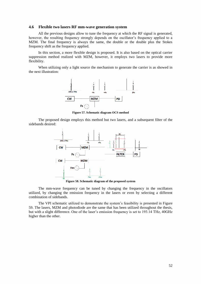
52
4.6 Flexible two lasers RF mm-wave generation system
All the previous designs allow to tune the frequency at which the RF signal is generated,
however, the resulting frequency strongly depends on the oscillator’s frequency applied to a
MZM. The final frequency is always the same, the double or the double plus the Stokes
frequency shift as the frequency applied.
In this section, a more flexible design is proposed. It is also based on the optical carrier
suppression method realized with MZM, however, it employs two lasers to provide more
flexibility.
When utilizing only a light source the mechanism to generate the carrier is as showed in
the next illustration:
Figure 57. Schematic diagram OCS method
The proposed design employs this method but two lasers, and a subsequent filter of the
sidebands desired:
Figure 58. Schematic diagram of the proposed system
The mm-wave frequency can be tuned by changing the frequency in the oscillators
utilized, by changing the emission frequency in the lasers or even by selecting a different
combination of sidebands.
The VPI schematic utilized to demonstrate the system’s feasibility is presented in Figure
59. The lasers, MZM and photodiode are the same that has been utilized throughout the thesis,
but with a slight difference. One of the laser’s emission frequency is set to 193.14 THz, 40GHz
higher than the other.
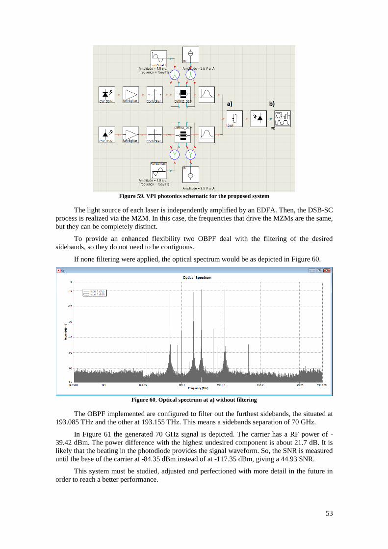
53
Figure 59. VPI photonics schematic for the proposed system
The light source of each laser is independently amplified by an EDFA. Then, the DSB-SC
process is realized via the MZM. In this case, the frequencies that drive the MZMs are the same,
but they can be completely distinct.
To provide an enhanced flexibility two OBPF deal with the filtering of the desired
sidebands, so they do not need to be contiguous.
If none filtering were applied, the optical spectrum would be as depicted in Figure 60.
Figure 60. Optical spectrum at a) without filtering
The OBPF implemented are configured to filter out the furthest sidebands, the situated at
193.085 THz and the other at 193.155 THz. This means a sidebands separation of 70 GHz.
In Figure 61 the generated 70 GHz signal is depicted. The carrier has a RF power of -
39.42 dBm. The power difference with the highest undesired component is about 21.7 dB. It is
likely that the beating in the photodiode provides the signal waveform. So, the SNR is measured
until the base of the carrier at -84.35 dBm instead of at -117.35 dBm, giving a 44.93 SNR.
This system must be studied, adjusted and perfectioned with more detail in the future in
order to reach a better performance.
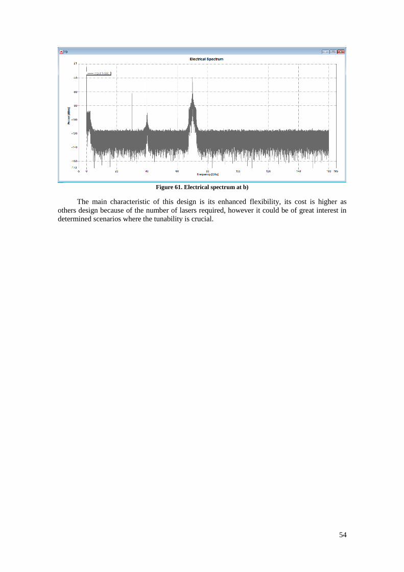
54
Figure 61. Electrical spectrum at b)
The main characteristic of this design is its enhanced flexibility, its cost is higher as
others design because of the number of lasers required, however it could be of great interest in
determined scenarios where the tunability is crucial.

55
Chapter 5. Budget
Once the designs viability is demonstrated, is the turn to talk about the cost of
implementing such schemes. A very important aspect in a network deployment is the economic
cost. The implementation speed and success of the new standard between the operators largely
depends on this aspect. Therefore, a budget of every design is estimated to use it as an indicator
of each design feasibility to be utilized.
In the following budgets, the photodiode receiver, the data generation and the fiber optic
used to transmit the signal are not included as they are supposed to be the same in all the
designs, and their price depends on the modulation format, the physical separation between the
generator and the receiver, etc.
The optoelectronic components required for the designs and their prices have been
extracted from the following web pages with the intention of calculating a primary budget:
www.thorlabs.com [35], www.digikey.com [36]and www.mouser.com [37].
As showed with the next budgets, the MWP based link transmission design is the
cheapest with a difference of about 2.000,00 € with the second cheapest design. Moreover, the
designs described in section 4.4, 4.5 and 4.6 are the most expensive.
The MWP based design from section 4.3 has the following estimated budget:
Quantity Price Total
CW DFB Laser x 1 2490,00 € 2490,00 €
EDFA x 2 3690,00 € 7380,00 €
PC x 2 166,15 € 332,30 €
MZM x 1 1998,00 € 1998,00 €
15 GHz Oscillator x 1 36,73 € 36,73 €
DC Source x 1 988,71 € 988,71 €
OBPF x 1 84,75 € 84,75 €
Total 13310,49 €
Table 3. Estimation budget design from section 4.3

56
The conventional design from section 4.2 has the following estimated budget:
The SBS based design with fine tunability from section 4.4 has the following estimated
budget:
The fiber included in the budget is the employed to realize the frequency shift based on
the SBS effect.
Quantity Price Total
CW DFB Laser x 1 2.490,00 € 2.490,00 €
EDFA x 2 3.690,00 € 7.380,00 €
PC x 2 166,15 € 332,30 €
MZM x 1 1.998,00 € 1.998,00 €
30 GHz Oscillator x 1 60,45 € 60,45 €
DC Source x 1 988,71 € 988,71 €
OBPF x 1 84,75 € 169,50 €
Phase Shifter x 1 2.249,00 € 2.249,00 €
Optical coupler x 1 3,86 € 3,86 €
Total 15.671,82 €
Table 4. Estimation budget design from section 4.2
Quantity Price Total
CW DFB Laser x 1 2.490,00 € 2.490,00 €
EDFA x 1 3.690,00 € 3.690,00 €
PC x 1 166,15 € 166,15 €
MZM x 1 1.998,00 € 1.998,00 €
15 GHz Oscillator x 1 36,73 € 36,73 €
DC Source x 1 988,71 € 988,71 €
Circulator x 2 547,00 € 1.094,00 €
Filter FBG x 1 427,50 € 427,50 €
Optical coupler x 1 3,86 € 3,86 €
10 km HNLF x 1 4.310,00 € 4.310,00 €
Total 15.204,95 € Table 5. Estimation budget design from section 4.4

57
In the budget for the triangular-shaped pulses generator from section 4.5 the fiber
required to produce the Stoke frequency shift is included:
This is the most expensive system due to the frequency shifter module, realized with the
double sideband carrier suppression method and a OBPF.
The budget of the two lasers design is also expensive because of the components
duplication:
Quantity Price Total
CW DFB Laser x 1 2.490,00 € 2.490,00 €
EDFA x 2 3.690,00 € 7.380,00 €
PC x 2 166,15 € 332,30 €
MZM x 1 1.998,00 € 1.998,00 €
15 GHz Oscillator x 1 36,73 € 36,73 €
DC Source x 1 988,71 € 988,71 €
Frequency Shifter x 2 2.082,75 € 2.082,75 €
Circulator x 1 547,00 € 547,00 €
10 km HNLF x 1 4.310,00 € 4.310,00 €
OBPF x 2 84,75 € 169,50 €
Isolator x 1 190,00 € 190,00 €
Total 20.524,99 €
Table 6. Estimated budget for the design from section 4.5
Quantity Price Total
CW DFB Laser x 2 2.490,00 € 4.980,00 €
EDFA x 2 3.690,00 € 7.380,00 €
PC x 2 166,15 € 332,30 €
MZM x 2 1.998,00 € 3.996,00 €
15 GHz Oscillator x 2 36,73 € 73,46 €
DC Source x 2 988,71 € 1.977,42 €
OBPF x 2 84,75 € 169,50 €
Optical coupler x 1 3,86 € 7,72 €
Total 18.916,40 € Table 7. Estimated budget for the system from section 4.6
58
Chapter 6. Conclusions and Future Lines
6.1 Conclusions
In this thesis, several RF mm-wave signal generation systems have been proposed and
simulated. The simulation and analysis emerge different conclusions:
• After showing a conventional mm-wave data transmission RoF system, an
alternative design based on MWP techniques has been demonstrated. Both are
able to transmit up to 10 Gbps and the mm-wave carriers generated have a similar
quality. However, from the point of view of the data transmission performance
and the equipment cost, the MWP based design is recognised as a better option.
• Besides, the successful performance of the MWP based design, it has the
economic advantage of employing an oscillator with the half frequency than the
other design. In such high frequency levels, the oscillator’s price rises
considerably. So, it has a really satisfactory performance with a lesser economic
impact.
• An additional generator system based on the same MWP principle as the
alternative transmission design is simulated. It also employs a frequency shift
module based on the SBS effect to increase the generated carrier frequency
without employing a higher frequency oscillator. Therefore, it allows higher
frequency RF mm-wave signal generation without incurring in more expensive
oscillators and a better tunability performance by not only enabling to tune the
signal frequency with the frequency driven the MZM but also by benefiting from
the SBS characteristics of the fiber employed.
• Microwave photonic techniques together with SBS effect can not only generate
high frequency signals but also build triangular-shaped high frequency pulses as
demonstrated. Making use of the techniques explained, an only odd-order
harmonics signal is produced. It contains only two odd-order harmonics but they
are enough.
• A design based on the OCS method but employing two lasers is introduced to
provide an enhanced flexibility. By utilizing two lasers with different emission
frequency, modulating them with MZM driven with distinct frequencies and
filtering the sidebands desired a more flexible system is achieved. The higher cost
generated by the employment of two lasers is compensated by the flexibility
provided.
• Lastly but not least, the higher cost from the last three designs is compensated by
its contributions. Besides, the studies are still immature and must be deeply
investigated before discarding them.
59
6.2 Future Lines
Once the work is finalized, some future research lines can be identified whether through
the difficulties presented with the simulation platform software or their interest. The proposed
future research areas are:
• Test the data transmission in every scheme presented. Not only is important the
quality of the carrier generated but also if it is suitable for data transmission.
• Study the systems performance when employing different modulation format. It
hasn’t been done in this thesis due to the problems obtained when trying N-QAM
data transmitting.
• Feasibility of using a Fabry-Perot laser instead of two DFB lasers in the last
design. If two spectral lines of the laser can be filtered and modulated through a
MZM, a similar behaviour could be reached without incurring in the higher cost
of utilizing two lasers. However, as the spectral lines are not completely
independent, the system should be deeply studied.
• Study and improvement of the design proposed in section 4.6.
• Once the theoretical and simulation work is realized is especially important to
check the experimental behaviour. So, the experimental study is left to
subsequent researches.
• The combined operation of RF mm-wave signal generation with optical
conformation systems is an area still to investigate.

60
References
[1] X. Hou, X. Wang, H. Jiang, and H. Kayama, “Investigation of Massive MIMO in Dense
Small Cell Deployment for 5G,” in Vehicular Technology Conference (VTC-Fall), 2016
IEEE 84th, 2016, pp. 1–6.
[2] G. Liu et al., “3-D-MIMO With Massive Antennas Paves the Way to 5G Enhanced Mobile
Broadband: From System Design to Field Trials,” IEEE J. Sel. Areas Commun., vol. 35, no.
6, pp. 1222–1233, Jun. 2017.
[3] L. Wan, M. Zhou, and R. Wen, “Evolving LTE with flexible duplex,” in Globecom
Workshops (GC Wkshps), 2013 IEEE, 2013, pp. 49–54.
[4] P. Pirinen, “Challenges and possibilities for flexible duplexing in 5G networks,” in
Computer Aided Modelling and Design of Communication Links and Networks (CAMAD),
2015 IEEE 20th International Workshop on, 2015, pp. 6–10.
[5] U. Siddique, H. Tabassum, E. Hossain, and D. I. Kim, “Wireless backhauling of 5G small
cells: Challenges and solution approaches,” IEEE Wirel. Commun., vol. 22, no. 5, pp. 22–
31, 2015.
[6] R.-A. Pitaval, O. Tirkkonen, R. Wichman, K. Pajukoski, E. Lahetkangas, and E. Tiirola,
“Full-duplex self-backhauling for small-cell 5G networks,” IEEE Wirel. Commun., vol. 22,
no. 5, pp. 83–89, 2015.
[7] S. Samarakoon, M. Bennis, W. Saad, and M. Latva-aho, “Backhaul-Aware Interference
Management in the Uplink of Wireless Small Cell Networks,” IEEE Trans. Wirel.
Commun., vol. 12, no. 11, pp. 5813–5825, Nov. 2013.
[8] X. Shen, “Device-to-device communication in 5G cellular networks,” IEEE Netw., vol. 29,
no. 2, pp. 2–3, 2015.
[9] K. Doppler, M. Rinne, C. Wijting, C. B. Ribeiro, and K. Hugl, “Device-to-device
communication as an underlay to LTE-advanced networks,” IEEE Commun. Mag., vol. 47,
no. 12, 2009.
[10] P. Janis, V. Koivunen, C. Ribeiro, J. Korhonen, K. Doppler, and K. Hugl, “Interference-
aware resource allocation for device-to-device radio underlaying cellular networks,” in
Vehicular Technology Conference, 2009. VTC Spring 2009. IEEE 69th, 2009, pp. 1–5.
[11] Y.-L. Chung, “A study of advanced D2D transmission for use in 5G cellular systems,” in
Information Networking (ICOIN), 2017 International Conference on, 2017, pp. 298–302.
[12] N. Alliance, “5G white paper,” Gener. Mob. Netw. White Pap., 2015.
[13] Ericsson, “5G Radio Access: Technology and Capabilities,” White Pap., Feb. 2015.
[14] S. Tombaz, P. Frenger, F. Athley, E. Semaan, C. Tidestav, and A. Furuskar, “Energy
Performance of 5G-NX Wireless Access Utilizing Massive Beamforming and an Ultra-
Lean System Design,” 2014, pp. 1–7.
[15] G.-K. Chang and C. Liu, “1–100GHz microwave photonics link technologies for next-
generation WiFi and 5G wireless communications,” in Microwave Photonics (MWP), 2013
International Topical Meeting on, 2013, pp. 5–8.
[16] R. Waterhouse and D. Novack, “Realizing 5G: Microwave Photonics for 5G Mobile
Wireless Systems,” IEEE Microw. Mag., vol. 16, no. 8, pp. 84–92, Sep. 2015.
[17] M. Talwar, “5G Network a Zero Distance Connectivity Between People,” Int. J. Emerg.
Technol., vol. 6, no. 1, p. 110, 2015.
[18] S. Methley, W. Webb, S. Walker, and J. Parker, “5G Candidate Band Study.” Quotient
Associates, Mar-2015.

61
[19] FCC, “FCC Spectrum Frontiers (mmW) Order on 28373964-71GHz and Further Notice of
Proposed Rulemaking (FNPRM).” 14-Jul-2016.
[20] “Framework and overall objectives of the future development of IMT for 2020 and
beyond,” Recommendation ITU-R M-2083-0, Sep. 2015.
[21] “Studies on frequency-related matters for International Mobile Telecommunications
identification including possible additional allocations to the mobile services on a primary
basis in portion(s) of the frequency range between 24.25 and 86 GHz for the future
development of International Mobile Telecommunications for 2020 and beyond,”
Resolution Resolution 238 (WRC-15), Nov. 2015.
[22] ITU-R, “Minimum requirements related to technical performance for IMT-2020 radio
interface(s),” IMT-2020.TECH PERF REQ, Feb. 2017.
[23] K. Xu et al., “Microwave photonics: radio-over-fiber links, systems, and applications
[Invited],” Photonics Res., vol. 2, no. 4, p. B54, Aug. 2014.
[24] C. H. Cox, Analog Optical Links: Theory and Practice. Cambridge University Press, 2006.
[25] Z. Cao, “Radio beam steering in indoor fibre-wireless networks,” Power DBm, vol. 20, no.
10, p. 0, 2015.
[26] X. Liu et al., “Photonic Generation of Triangular-Shaped Microwave Pulses Using SBS-
Based Optical Carrier Processing,” J. Light. Technol., vol. 32, no. 20, pp. 3797–3802, Oct.
2014.
[27] F. Xin, J. Yan, and Q. Liu, “An Optical Microwave Generator based on Stimulated
Brillouin Scattering with Fine Tunability,” Sch. Electron. Inf. Eng. Beihang Univ. Beijing
China.
[28] Huanfa Peng et al., “Tunable DC-60 GHz RF Generation Utilizing a Dual-Loop
Optoelectronic Oscillator Based on Stimulated Brillouin Scattering,” J. Light. Technol., vol.
33, no. 13, pp. 2707–2715, Jul. 2015.
[29] Chung-Yu Lin, Yu-Chieh Chi, Cheng-Tin Tsai, Huai-Yung Wang, and Gong-Ru Lin, “39-
GHz Millimeter-Wave Carrier Generation in Dual-Mode Colorless Laser Diode for OFDM-
MMWoF Transmission,” IEEE J. Sel. Top. Quantum Electron., vol. 21, no. 6, pp. 609–618,
Nov. 2015.
[30] W. Roh et al., “Millimeter-wave beamforming as an enabling technology for 5G cellular
communications: theoretical feasibility and prototype results,” IEEE Commun. Mag., vol.
52, no. 2, pp. 106–113, 2014.
[31] Z. Cao, X. Zhao, F. M. Soares, N. Tessema, and A. M. J. Koonen, “38-GHz Millimeter
Wave Beam Steered Fiber Wireless Systems for 5G Indoor Coverage: Architectures,
Devices, and Links,” IEEE J. Quantum Electron., vol. 53, no. 1, pp. 1–9, Feb. 2017.
[32] J. Capmany, B. Ortega, and D. Pastor, “A tutorial on microwave photonic filters,” J. Light.
Technol., vol. 24, no. 1, pp. 201–229, Jan. 2006.
[33] J. Zhang, J. Yu, N. Chi, F. Li, and X. Li, “Experimental demonstration of 24-Gb/s CAP-
64QAM radio-over-fiber system over 40-GHz mm-wave fiber-wireless transmission,” Opt.
Express, vol. 21, no. 22, p. 26888, Nov. 2013.
[34] M. Weiß, M. Huchard, A. Stohr, B. Charbonnier, S. Fedderwitz, and D. S. Jager, “60-GHz
Photonic Millimeter-Wave Link for Short- to Medium-Range Wireless Transmission Up to
12.5 Gb/s,” J. Light. Technol., vol. 26, no. 15, pp. 2424–2429, Aug. 2008.
[35] “Thorlabs, Inc. - Your Source for Fiber Optics, Laser Diodes, Optical Instrumentation and
Polarization Measurement & Control,” Thorlabs, Inc. - Your Source for Fiber Optics, Laser
Diodes, Optical Instrumentation and Polarization Measurement & Control. [Online].
Available: http://www.thorlabs.com. [Accessed: 11-Sep-2017].

62
[36] “DigiKey Electronics - Electronic Components Distributor.” [Online]. Available:
http://www.digikey.com. [Accessed: 11-Sep-2017].
[37] “Mouser Electronics Spain - Electronic Components Distributor.” [Online]. Available:
http://www.mouser.com. [Accessed: 11-Sep-2017].