
Fiber Bragg gratings for microwave photonics subsystems
17
Fiber Bragg gratings for microwave photonics subsystems Chao Wang and Jianping Yao * Microwave Photonics Research Laboratory, School of Electrical Engineering and Computer Science University of Ottawa, Ontario K1N 6N5, Canada *[email protected] Abstract: Microwave photonics (MWP) is an emerging filed in which photonic technologies are employed to enable and enhance functionalities in microwave systems which are usually very challenging to fulfill directly in the microwave domain. Various photonic devices have been used to achieve the functions. A fiber Bragg grating (FBG) is one of the key components in microwave photonics systems due to its unique features such as flexible spectral characteristics, low loss, light weight, compact footprint, and inherent compatibility with other fiber-optic devices. In this paper, we discuss the recent development in employing FBGs for various microwave photonics subsystems, with an emphasis on subsystems for microwave photonic signal processing and microwave arbitrary waveform generation. The limitations and potential solutions are also discussed. © 2013 Optical Society of America OCIS codes: (060.2340) Fiber optics components; (060.5625) Radio frequency photonics; (350.4010) Microwaves. References and links 1. J. Capmany and D. Novak, “Microwave photonics combines two worlds,” Nat. Photonics 1(6), 319–330 (2007). 2. A. J. Seeds, “Microwave photonics,” IEEE Trans. Microw. Theory Tech. 50(3), 877–887 (2002). 3. A. J. Seeds and K. J. Williams, “Microwave photonics,” J. Lightwave Technol. 24(12), 4628–4641 (2006). 4. J. P. Yao, “Microwave Photonics,” J. Lightwave Technol. 27(3), 314–335 (2009). 5. J. P. Yao, “A tutorial on microwave photonics - Part I,” IEEE Photon. Soc. Newsletter 26(2), 4–12 (2012). 6. J. P. Yao, “A tutorial on microwave photonics - Part II,” IEEE Photon. Soc. Newsletter 26(3), 5–12 (2012). 7. K. O. Hill, B. Malo, F. Bilodeau, D. C. Johnson, and J. Albert, “Bragg gratings fabricated in monomode photosensitive optical-Fiber by UV exposure through a phase mask,” Appl. Phys. Lett. 62(10), 1035–1037 (1993). 8. T. Erdogan, “Fiber grating spectra,” J. Lightwave Technol. 15(8), 1277–1294 (1997). 9. R. Kashyap, Fiber Bragg Gratings (Academic Press, 1999). 10. C. R. Giles, “Lightwave applications of fiber Bragg gratings,” J. Lightwave Technol. 15(8), 1391–1404 (1997). 11. Y. J. Rao, “In-fibre Bragg grating sensors,” Meas. Sci. Technol. 8(4), 355–375 (1997). 12. R. A. Minasian, “Photonic signal processing of high-speed signals using fiber gratings,” Opt. Fiber Technol. 6(2), 91–108 (2000). 13. J. Capmany, D. Pastor, B. Ortega, J. L. Cruz, and M. V. Andres; JosÉ Capmany, Daniel Pastor, Beatri, “Applications of fiber Bragg gratings to microwave photonics,” Fiber Integrated Opt. 19(4), 483–494 (2000). 14. C. Wang and J. P. Yao, “Fiber Bragg gratings for microwave photonics applications,” in Microwave Photonics, Second Edition, C. H. Lee, ed. (CRC Press, 2013), pp. 125–174. 15. S. Blais and J. P. Yao, “Photonic true-time delay beamforming based on superstructured fiber Bragg gratings with linearly increasing equivalent chirps,” J. Lightwave Technol. 27(9), 1147–1154 (2009). 16. R. A. Minasian, “Photonic signal processing of microwave signals,” IEEE Trans. Microw. Theory Tech. 54(2), 832–846 (2006). 17. S. Blais and J. P. Yao, “Optical single sideband modulation using an ultranarrow dual-transmission-band fiber Bragg grating,” IEEE Photon. Technol. Lett. 18(21), 2230–2232 (2006). 18. J. P. Yao, F. Zeng, and Q. Wang, “Photonic generation of Ultra-Wideband signals,” J. Lightwave Technol. 25(11), 3219–3235 (2007). 19. W. Li, W. Zhang, and J. P. Yao, “A wideband 360° photonic-assisted microwave phase shifter using a polarization modulator and a polarization-maintaining fiber Bragg grating,” Opt. Express 20(28), 29838–29843 (2012). 20. W. Li and J. P. Yao, “Investigation of photonically assisted microwave frequency multiplication based on external modulation,” IEEE Trans. Microw. Theory Tech. 58(11), 3259–3268 (2010). #192101 - $15.00 USD Received 11 Jun 2013; revised 8 Aug 2013; accepted 8 Aug 2013; published 23 Sep 2013 (C) 2013 OSA 23 September 2013 | Vol. 21, No. 19 | DOI:10.1364/OE.21.022868 | OPTICS EXPRESS 22868
Transcript of Fiber Bragg gratings for microwave photonics subsystems
Fiber Bragg gratings for microwave photonics subsystems
Chao Wang and Jianping Yao* Microwave Photonics Research Laboratory, School of Electrical Engineering and Computer Science University of
Ottawa, Ontario K1N 6N5, Canada *[email protected]
Abstract: Microwave photonics (MWP) is an emerging filed in which photonic technologies are employed to enable and enhance functionalities in microwave systems which are usually very challenging to fulfill directly in the microwave domain. Various photonic devices have been used to achieve the functions. A fiber Bragg grating (FBG) is one of the key components in microwave photonics systems due to its unique features such as flexible spectral characteristics, low loss, light weight, compact footprint, and inherent compatibility with other fiber-optic devices. In this paper, we discuss the recent development in employing FBGs for various microwave photonics subsystems, with an emphasis on subsystems for microwave photonic signal processing and microwave arbitrary waveform generation. The limitations and potential solutions are also discussed.
© 2013 Optical Society of America
OCIS codes: (060.2340) Fiber optics components; (060.5625) Radio frequency photonics; (350.4010) Microwaves.
References and links 1. J. Capmany and D. Novak, “Microwave photonics combines two worlds,” Nat. Photonics 1(6), 319–330 (2007). 2. A. J. Seeds, “Microwave photonics,” IEEE Trans. Microw. Theory Tech. 50(3), 877–887 (2002). 3. A. J. Seeds and K. J. Williams, “Microwave photonics,” J. Lightwave Technol. 24(12), 4628–4641 (2006). 4. J. P. Yao, “Microwave Photonics,” J. Lightwave Technol. 27(3), 314–335 (2009). 5. J. P. Yao, “A tutorial on microwave photonics - Part I,” IEEE Photon. Soc. Newsletter 26(2), 4–12 (2012). 6. J. P. Yao, “A tutorial on microwave photonics - Part II,” IEEE Photon. Soc. Newsletter 26(3), 5–12 (2012). 7. K. O. Hill, B. Malo, F. Bilodeau, D. C. Johnson, and J. Albert, “Bragg gratings fabricated in monomode
photosensitive optical-Fiber by UV exposure through a phase mask,” Appl. Phys. Lett. 62(10), 1035–1037 (1993).
8. T. Erdogan, “Fiber grating spectra,” J. Lightwave Technol. 15(8), 1277–1294 (1997). 9. R. Kashyap, Fiber Bragg Gratings (Academic Press, 1999). 10. C. R. Giles, “Lightwave applications of fiber Bragg gratings,” J. Lightwave Technol. 15(8), 1391–1404 (1997). 11. Y. J. Rao, “In-fibre Bragg grating sensors,” Meas. Sci. Technol. 8(4), 355–375 (1997). 12. R. A. Minasian, “Photonic signal processing of high-speed signals using fiber gratings,” Opt. Fiber Technol.
6(2), 91–108 (2000). 13. J. Capmany, D. Pastor, B. Ortega, J. L. Cruz, and M. V. Andres; JosÉ Capmany, Daniel Pastor, Beatri,
“Applications of fiber Bragg gratings to microwave photonics,” Fiber Integrated Opt. 19(4), 483–494 (2000). 14. C. Wang and J. P. Yao, “Fiber Bragg gratings for microwave photonics applications,” in Microwave Photonics,
Second Edition, C. H. Lee, ed. (CRC Press, 2013), pp. 125–174. 15. S. Blais and J. P. Yao, “Photonic true-time delay beamforming based on superstructured fiber Bragg gratings
with linearly increasing equivalent chirps,” J. Lightwave Technol. 27(9), 1147–1154 (2009). 16. R. A. Minasian, “Photonic signal processing of microwave signals,” IEEE Trans. Microw. Theory Tech. 54(2),
832–846 (2006). 17. S. Blais and J. P. Yao, “Optical single sideband modulation using an ultranarrow dual-transmission-band fiber
Bragg grating,” IEEE Photon. Technol. Lett. 18(21), 2230–2232 (2006). 18. J. P. Yao, F. Zeng, and Q. Wang, “Photonic generation of Ultra-Wideband signals,” J. Lightwave Technol.
25(11), 3219–3235 (2007). 19. W. Li, W. Zhang, and J. P. Yao, “A wideband 360° photonic-assisted microwave phase shifter using a
polarization modulator and a polarization-maintaining fiber Bragg grating,” Opt. Express 20(28), 29838–29843 (2012).
20. W. Li and J. P. Yao, “Investigation of photonically assisted microwave frequency multiplication based on external modulation,” IEEE Trans. Microw. Theory Tech. 58(11), 3259–3268 (2010).
#192101 - $15.00 USD Received 11 Jun 2013; revised 8 Aug 2013; accepted 8 Aug 2013; published 23 Sep 2013(C) 2013 OSA 23 September 2013 | Vol. 21, No. 19 | DOI:10.1364/OE.21.022868 | OPTICS EXPRESS 22868
21. Z. Li, C. Wang, M. Li, H. Chi, X. Zhang, and J. P. Yao, “Instantaneous microwave frequency measurement using a special fiber Bragg grating,” IEEE Microw. Wirel. Compon. Lett. 21(1), 52–54 (2011).
22. W. Li and J. P. Yao, “An optically tunable frequency-multiplying optoelectronic oscillator,” IEEE Photon. Technol. Lett. 24(10), 812–814 (2012).
23. J. P. Yao, “Photonic generation of microwave arbitrary waveforms,” Opt. Commun. 284(15), 3723–3736 (2011). 24. J. Capmany, B. Ortega, and D. Pastor, “A tutorial on microwave photonic filters,” J. Lightwave Technol. 24(1),
201–229 (2006). 25. D. B. Hunter and R. A. Minasian, “Microwave optical filters using in-fiber Bragg grating arrays,” IEEE Microw.
Guided Wave Lett. 6(2), 103–105 (1996). 26. X. K. Yi and R. A. Minasian, “Noise mitigation in spectrum sliced microwave photonic signal processors,” J.
Lightwave Technol. 24(12), 4959–4965 (2006). 27. J. Mora, M. V. Andrés, J. L. Cruz, B. Ortega, J. Capmany, D. Pastor, and S. Sales, “Tunable all-optical negative
multitap microwave filters based on uniform fiber Bragg gratings,” Opt. Lett. 28(15), 1308–1310 (2003). 28. F. Zeng, J. Wang, and J. P. Yao, “All-optical microwave bandpass filter with negative coefficients based on a
phase modulator and linearly chirped fiber Bragg gratings,” Opt. Lett. 30(17), 2203–2205 (2005). 29. Y. Yan, S. Blais, and J. P. Yao, “Tunable photonic microwave bandpass filter with negative coefficients
implemented using an optical phase modulator and chirped fiber Bragg gratings,” J. Lightwave Technol. 25(11), 3283–3288 (2007).
30. T. Chen, X. Yi, T. Huang, and R. A. Minasian, “Multiple-bipolar-tap tunable spectrum sliced microwave photonic filter,” Opt. Lett. 35(23), 3934–3936 (2010).
31. S. R. Blals and J. P. Yao, “Tunable photonic microwave filter using a superstructured FBG with two reflection bands having complementary chirps,” IEEE Photon. Technol. Lett. 20(3), 199–201 (2008).
32. F. Zeng and J. P. Yao, “Ultrawideband impulse radio signal generation using a high-speed electrooptic phase modulator and a fiber-Bragg-grating-based frequency discriminator,” IEEE Photon. Technol. Lett. 18(19), 2062–2064 (2006).
33. A. Loayssa, J. Capmany, M. Sagues, and J. Mora, “Demonstration of incoherent microwave photonic filters with all optical complex coefficients,” IEEE Photon. Technol. Lett. 18(16), 1744–1746 (2006).
34. Y. Yan and J. P. Yao, “A tunable photonic microwave filter with a complex coefficient using an optical RF phase shifter,” IEEE Photon. Technol. Lett. 19(19), 1472–1474 (2007).
35. Y. Dai and J. P. Yao, “Nonuniformly-spaced photonic microwave delayline filter,” Opt. Express 16(7), 4713–4718 (2008).
36. Y. Dai and J. P. Yao, “Nonuniformly spaced photonic microwave delay-line filters and applications,” IEEE Trans. Microw. Theory Tech. 58(11), 3279–3289 (2010).
37. C. Wang and J. P. Yao, “A nonuniformly spaced microwave photonic filter using a spatially discrete chirped fiber Bragg grating,” IEEE Photon. Technol. Lett. submitted.
38. C. Wang and J. P. Yao, “Chirped microwave pulse compression using a photonic microwave filter with a nonlinear phase response,” IEEE Trans. Microw. Theory Tech. 57(2), 496–504 (2009).
39. Y. Dai and J. P. Yao, “Chirped microwave pulse generation using a photonic microwave delay-line filter with a quadratic phase response,” IEEE Photon. Technol. Lett. 21(9), 569–571 (2009).
40. H. Shahoei and J. P. Yao, “Tunable microwave photonic phase shifter based on slow and fast light effects in a tilted fiber Bragg grating,” Opt. Express 20(13), 14009–14014 (2012).
41. H. Shahoei, M. Li, and J. P. Yao, “Continuously tunable time delay using an optically pumped linearly chirped fiber Bragg grating,” J. Lightwave Technol. 29(10), 1465–1472 (2011).
42. H. Shahoei and J. P. Yao, “A continuously tunable multi-tap complex-coefficient microwave photonic filter based on a tilted fiber Bragg grating,” Opt. Express 21(6), 7521–7527 (2013).
43. W. Li, M. Li, and J. P. Yao, “A narrow-passband and frequency-tunable micro-wave photonic filter based on phase-modulation to intensity-modulation conversion using a phase-shifted fiber Bragg grating,” IEEE Trans. Microw. Theory Tech. 60(5), 1287–1296 (2012).
44. M. Li and J. P. Yao, “All-optical short-time Fourier transform based on a temporal pulse shaping system incorporating an array of cascaded linearly chirped fiber Bragg gratings,” IEEE Photon. Technol. Lett. 23(20), 1439–1441 (2011).
45. Z. Li, W. Li, H. Chi, X. Zhang, and J. P. Yao, “Optical single-sideband modulation using a fiber-Bragg-grating-based optical Hilbert transformer,” IEEE Photon. Technol. Lett. 23(9), 558–560 (2011).
46. M. Li and J. P. Yao, “All-fiber temporal photonic fractional Hilbert transformer based on a directly designed fiber Bragg grating,” Opt. Lett. 35(2), 223–225 (2010).
47. M. Li, D. Janner, J. P. Yao, and V. Pruneri, “Arbitrary-order all-fiber temporal differentiator based on a fiber Bragg grating: design and experimental demonstration,” Opt. Express 17(22), 19798–19807 (2009).
48. M. Li and J. P. Yao, “Multichannel arbitrary-order photonic temporal differentiator for wavelength-division-multiplexed signal processing using a single fiber Bragg grating,” J. Lightwave Technol. 29(17), 2506–2511 (2011).
49. M. Li, L. Shao, J. Albert, and J. P. Yao, “Continuously tunable photonic fractional temporal differentiator based
on tilted ber Bragg grating,” IEEE Photon. Technol. Lett. 23(4), 251–253 (2011).
50. H. Shahoei, J. Albert, and J. P. Yao, “Optically tunable fractional order temporal differentiator using an optically pumped tilted fiber Bragg grating,” IEEE Photon. Technol. Lett. 24(9), 370–372 (2012).
#192101 - $15.00 USD Received 11 Jun 2013; revised 8 Aug 2013; accepted 8 Aug 2013; published 23 Sep 2013(C) 2013 OSA 23 September 2013 | Vol. 21, No. 19 | DOI:10.1364/OE.21.022868 | OPTICS EXPRESS 22869
51. M. H. Asghari, C. Wang, J. Yao, and J. Azaña, “High-order passive photonic temporal integrators,” Opt. Lett. 35(8), 1191–1193 (2010).
52. M. A. Muriel, J. Azaña, and A. Carballar, “Real-time Fourier transformer based on fiber gratings,” Opt. Lett. 24(1), 1–3 (1999).
53. J. Chou, Y. Han, and B. Jalali, “Adaptive RF-photonic arbitrary waveform generator,” IEEE Photon. Technol. Lett. 15(4), 581–583 (2003).
54. I. S. Lin, J. D. McKinney, and A. M. Weiner, “Photonic synthesis of broadband microwave arbitrary waveforms applicable to ultra-wideband communication,” IEEE Microw. Wirel. Compon. Lett. 15(4), 226–228 (2005).
55. C. Wang, F. Zeng, and J. P. Yao, “All-fiber ultrawideband pulse generation based on spectral-shaping and dispersion-induced frequency-to-time conversion,” IEEE Photon. Technol. Lett. 19(3), 137–139 (2007).
56. J. P. Yao, “Photonics for Ultrawideband communications,” IEEE Microw. Mag. 10(4), 82–95 (2009). 57. C. Wang and J. P. Yao, “Photonic generation of chirped microwave pulses using superimposed chirped fiber
Bragg gratings,” IEEE Photon. Technol. Lett. 20(11), 882–884 (2008). 58. C. Wang and J. P. Yao, “Chirped microwave pulse generation based on optical spectral shaping and wavelength-
to-time mapping using a Sagnac loop mirror incorporating a chirped fiber Bragg grating,” J. Lightwave Technol. 27(16), 3336–3341 (2009).
59. M. Li and J. P. Yao, “Photonic generation of continuously tunable chirped microwave waveforms based on a temporal interferometer incorporating an optically-pumped linearly-chirped fiber Bragg grating,” IEEE Trans. Microw. Theory Tech. 59(12), 3531–3537 (2011).
60. C. Wang and J. P. Yao, “Photonic generation of chirped millimeter-wave pulses based on nonlinear frequency-to-time mapping in a nonlinearly chirped fiber Bragg grating,” IEEE Trans. Microw. Theory Tech. 56(2), 542–553 (2008).
61. C. Wang and J. P. Yao, “Simultaneous optical spectral shaping and wavelength-to-time mapping for photonic microwave arbitrary waveform generation,” IEEE Photon. Technol. Lett. 21(12), 793–795 (2009).
62. C. Wang and J. P. Yao, “Large time-bandwidth product microwave arbitrary waveform generation using a spatially discrete chirped fiber Bragg grating,” J. Lightwave Technol. 28(11), 1652–1660 (2010).
63. C. Wang and J. P. Yao, “Phase-coded millimeter-wave waveform generation using a spatially discrete chirped fiber Bragg grating,” IEEE Photon. Technol. Lett. 24(17), 1493–1495 (2012).
64. A. M. Weiner, J. P. Heritage, and E. M. Kirschner, “High-resolution femtosecond pulse shaping,” J. Opt. Soc. Am. B 5(8), 1563–1572 (1988).
65. C. Wang and J. P. Yao, “Fourier transform ultrashort optical pulse shaping using a single chirped fiber Bragg grating,” IEEE Photon. Technol. Lett. 21(19), 1375–1377 (2009).
66. J. P. Heritage and A. M. Weiner, “Optical systems and methods based upon temporal stretching, modulation and recompression of ultrashort pulses,” United States Patent 4928316, 1990.
67. H. Chi and J. P. Yao, “Symmetrical waveform generation based on temporal pulse shaping using amplitude-only modulator,” Electron. Lett. 43(7), 415–417 (2007).
68. M. Li, Y. C. Han, S. L. Pan, and J. P. Yao, “Experimental demonstration of symmetrical waveform generation based on amplitude-only modulation in a fiber-based temporal pulse shaping system,” IEEE Photon. Technol. Lett. 23(11), 715–717 (2011).
69. C. Wang, M. Li, and J. P. Yao, “Continuously tunable photonic microwave frequency multiplication by use of an unbalanced temporal pulse shaping system,” IEEE Photon. Technol. Lett. 22(17), 1285–1287 (2010).
70. M. Li, C. Wang, W. Li, and J. P. Yao, “An unbalanced temporal pulse shaping system for chirped microwave waveform generation,” IEEE Trans. Microw. Theory Tech. 58(11), 2968–2975 (2010).
71. H. Shahoei and J. P. Yao, “Continuously tunable microwave frequency multiplication by optically pumping linearly chirped fiber Bragg gratings in an unbalanced temporal pulse shaping system,” J. Lightwave Technol. 30(12), 1954–1959 (2012).
72. Y. Q. Liu, J. L. Yang, and J. P. Yao, “Continuous true-time-delay beamforming for phased array antenna using a tunable chirped fiber grating delay line,” IEEE Photon. Technol. Lett. 14(8), 1172–1174 (2002).
73. K. M. Feng, J. X. Chai, V. Grubsky, D. S. Starodubov, M. I. Hayee, S. Lee, X. Jiang, A. E. Willner, and J. Feinberg, “Dynamic dispersion compensation in a 10-Gb/s optical system using a novel voltage tuned nonlinearly chirped fiber Bragg grating,” IEEE Photon. Technol. Lett. 11(3), 373–375 (1999).
74. S. Matsumoto, M. Takabayashi, K. Yoshiara, T. Sugihara, T. Miyazaki, and F. Kubota, “Tunable dispersion slope compensator with a chirped fiber grating and a divided thin-film heater for 160-Gb/s RZ transmissions,” IEEE Photon. Technol. Lett. 16(4), 1095–1097 (2004).
75. P. Rugeland, Z. Yu, C. Sterner, O. Tarasenko, G. Tengstrand, and W. Margulis, “Photonic scanning receiver using an electrically tuned fiber Bragg grating,” Opt. Lett. 34(24), 3794–3796 (2009).
76. L. E. Adams, H. Mavoori, S. Jin, and R. P. Espindola, “Dynamic measurements of magnetically-strain tuned FBG for fast reconfigurable add/drop,” in Proc. OFC’99, 143–145 (1999)
77. D. Marpaung, C. Roeloffzen, R. Heideman, A. Leinse, S. Sales, and J. Capmany, “Integrated microwave photonics,” Laser Photon. Rev. 7(4), 506–538 (2013).
78. S. Khan, M. A. Baghban, and S. Fathpour, “Electronically tunable silicon photonic delay lines,” Opt. Express 19(12), 11780–11785 (2011).
79. I. Giuntoni, D. Stolarek, D. I. Kroushkov, J. Bruns, L. Zimmermann, B. Tillack, and K. Petermann, “Continuously tunable delay line based on SOI tapered Bragg gratings,” Opt. Express 20(10), 11241–11246 (2012).
#192101 - $15.00 USD Received 11 Jun 2013; revised 8 Aug 2013; accepted 8 Aug 2013; published 23 Sep 2013(C) 2013 OSA 23 September 2013 | Vol. 21, No. 19 | DOI:10.1364/OE.21.022868 | OPTICS EXPRESS 22870
80. K. A. Rutkowska, D. Duchesne, M. J. Strain, R. Morandotti, M. Sorel, and J. Azaña, “Ultrafast all-optical temporal differentiators based on CMOS-compatible integrated-waveguide Bragg gratings,” Opt. Express 19(20), 19514–19522 (2011).
1. Introduction
Microwave photonics is an area that studies the interaction between microwave and optical waves for the generation, distribution, control, processing and analysis of microwave signals by means of photonics [1–6]. Various photonic components have been employed in microwave photonics systems, such as optical sources, optical amplifiers, dispersive elements, electro-optical modulators, optical filters, and photodetectors. Most of microwave photonics systems are designed to operate at the 1550 nm band, to take advantage of the low-cost photonic devices developed for fiber optic communications in this wavelength band.
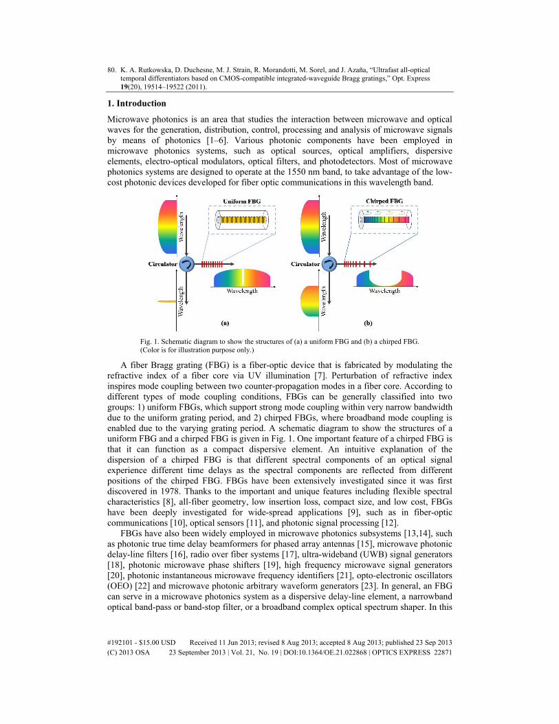
Fig. 1. Schematic diagram to show the structures of (a) a uniform FBG and (b) a chirped FBG. (Color is for illustration purpose only.)
A fiber Bragg grating (FBG) is a fiber-optic device that is fabricated by modulating the refractive index of a fiber core via UV illumination [7]. Perturbation of refractive index inspires mode coupling between two counter-propagation modes in a fiber core. According to different types of mode coupling conditions, FBGs can be generally classified into two groups: 1) uniform FBGs, which support strong mode coupling within very narrow bandwidth due to the uniform grating period, and 2) chirped FBGs, where broadband mode coupling is enabled due to the varying grating period. A schematic diagram to show the structures of a uniform FBG and a chirped FBG is given in Fig. 1. One important feature of a chirped FBG is that it can function as a compact dispersive element. An intuitive explanation of the dispersion of a chirped FBG is that different spectral components of an optical signal experience different time delays as the spectral components are reflected from different positions of the chirped FBG. FBGs have been extensively investigated since it was first discovered in 1978. Thanks to the important and unique features including flexible spectral characteristics [8], all-fiber geometry, low insertion loss, compact size, and low cost, FBGs have been deeply investigated for wide-spread applications [9], such as in fiber-optic communications [10], optical sensors [11], and photonic signal processing [12].
FBGs have also been widely employed in microwave photonics subsystems [13,14], such as photonic true time delay beamformers for phased array antennas [15], microwave photonic delay-line filters [16], radio over fiber systems [17], ultra-wideband (UWB) signal generators [18], photonic microwave phase shifters [19], high frequency microwave signal generators [20], photonic instantaneous microwave frequency identifiers [21], opto-electronic oscillators (OEO) [22] and microwave photonic arbitrary waveform generators [23]. In general, an FBG can serve in a microwave photonics system as a dispersive delay-line element, a narrowband optical band-pass or band-stop filter, or a broadband complex optical spectrum shaper. In this
#192101 - $15.00 USD Received 11 Jun 2013; revised 8 Aug 2013; accepted 8 Aug 2013; published 23 Sep 2013(C) 2013 OSA 23 September 2013 | Vol. 21, No. 19 | DOI:10.1364/OE.21.022868 | OPTICS EXPRESS 22871
paper, we discuss the recent development in employing FBGs for various microwave photonics subsystems, with an emphasis on subsystems for microwave photonic signal processing and microwave arbitrary waveform generation. The limitations and potential solutions are also discussed.
2. FBGs for microwave photonic signal processing
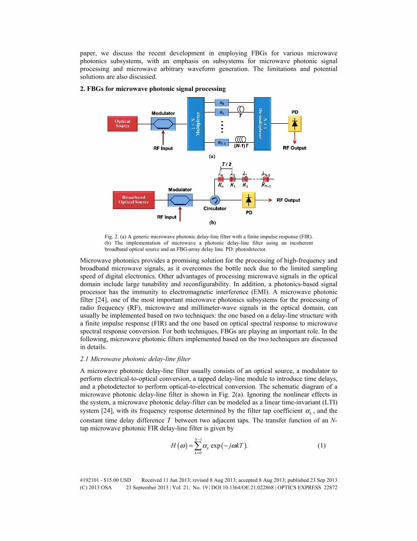
Fig. 2. (a) A generic microwave photonic delay-line filter with a finite impulse response (FIR). (b) The implementation of microwave a photonic delay-line filter using an incoherent broadband optical source and an FBG-array delay line. PD: photodetector.
Microwave photonics provides a promising solution for the processing of high-frequency and broadband microwave signals, as it overcomes the bottle neck due to the limited sampling speed of digital electronics. Other advantages of processing microwave signals in the optical domain include large tunability and reconfigurability. In addition, a photonics-based signal processor has the immunity to electromagnetic interference (EMI). A microwave photonic filter [24], one of the most important microwave photonics subsystems for the processing of radio frequency (RF), microwave and millimeter-wave signals in the optical domain, can usually be implemented based on two techniques: the one based on a delay-line structure with a finite impulse response (FIR) and the one based on optical spectral response to microwave spectral response conversion. For both techniques, FBGs are playing an important role. In the following, microwave photonic filters implemented based on the two techniques are discussed in details.
2.1 Microwave photonic delay-line filter
A microwave photonic delay-line filter usually consists of an optical source, a modulator to perform electrical-to-optical conversion, a tapped delay-line module to introduce time delays, and a photodetector to perform optical-to-electrical conversion. The schematic diagram of a microwave photonic delay-line filter is shown in Fig. 2(a). Ignoring the nonlinear effects in the system, a microwave photonic delay-filter can be modeled as a linear time-invariant (LTI) system [24], with its frequency response determined by the filter tap coefficient kα , and the
constant time delay difference T between two adjacent taps. The transfer function of an N-tap microwave photonic FIR delay-line filter is given by
( ) ( )1
0
exp .N
kk
H j kTω α ω−
=
= − (1)
#192101 - $15.00 USD Received 11 Jun 2013; revised 8 Aug 2013; accepted 8 Aug 2013; published 23 Sep 2013(C) 2013 OSA 23 September 2013 | Vol. 21, No. 19 | DOI:10.1364/OE.21.022868 | OPTICS EXPRESS 22872
where ω is the microwave angular frequency. ( )H ω has a multi-channel frequency response
with adjacent channels separated by the free spectral range (FSR), given by 2 / TπΩ = , with the mth channel centered at the frequency of mω = Ω .
The key device in a microwave photonic delay-line filter is the tapped optical delay-line module, which can be implemented using FBGs. Figure 2(b) shows a microwave photonic delay-line filter using an incoherent broadband optical source and an array of uniform FBGs [25]. The time delay difference is determined by the physical separation of adjacent FBGs, and the tap coefficients are equal to the reflectivities of the uniform FBGs, kR . Note that in
such a system, optical carriers (taps) are produced by slicing the spectrum of the incoherent broadband source using an array of FBGs. This spectrum-slicing method simplifies the implementation since it eliminates the need for a costly multi-wavelength laser source. However, the noise performance of a microwave photonic delay-line filter using a sliced light source is degraded due to the high noise level of an incoherent broadband source, such as an amplified spontaneous emission (ASE) light source or a light-emitting diode (LED) source. A comprehensive study of the filter transfer function of a spectrum-sliced microwave photonic delay-line filter and its noise characteristics can be found in [26].
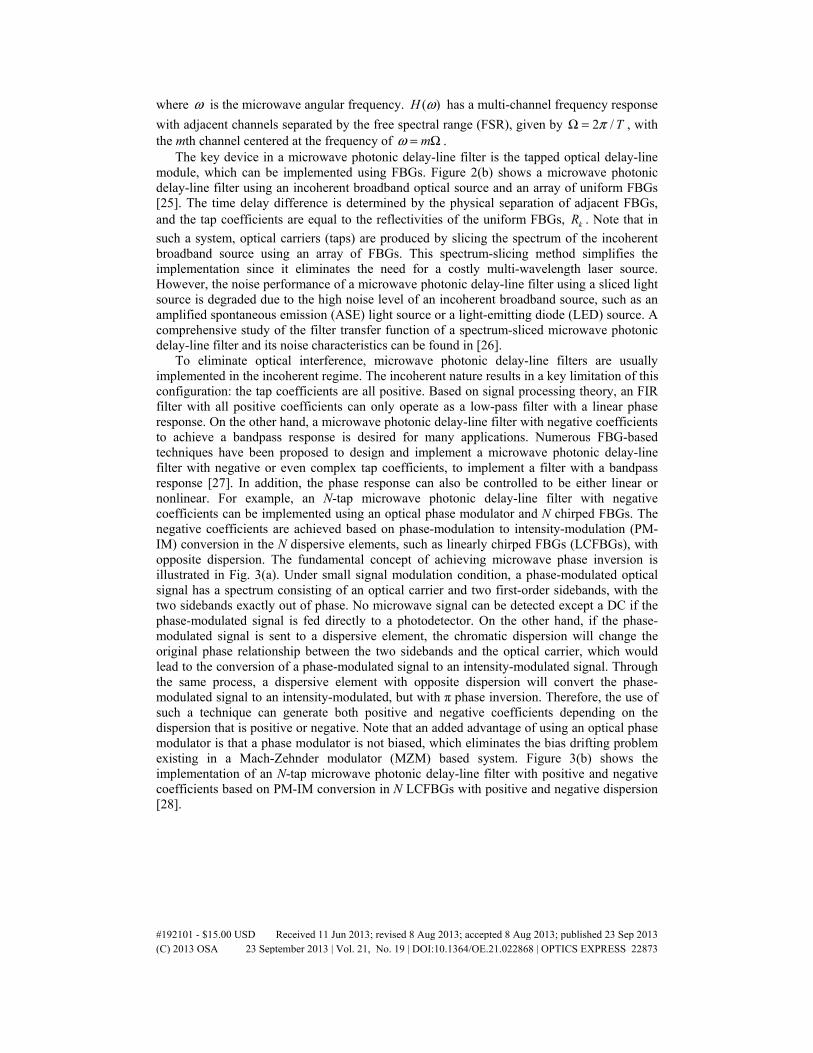
To eliminate optical interference, microwave photonic delay-line filters are usually implemented in the incoherent regime. The incoherent nature results in a key limitation of this configuration: the tap coefficients are all positive. Based on signal processing theory, an FIR filter with all positive coefficients can only operate as a low-pass filter with a linear phase response. On the other hand, a microwave photonic delay-line filter with negative coefficients to achieve a bandpass response is desired for many applications. Numerous FBG-based techniques have been proposed to design and implement a microwave photonic delay-line filter with negative or even complex tap coefficients, to implement a filter with a bandpass response [27]. In addition, the phase response can also be controlled to be either linear or nonlinear. For example, an N-tap microwave photonic delay-line filter with negative coefficients can be implemented using an optical phase modulator and N chirped FBGs. The negative coefficients are achieved based on phase-modulation to intensity-modulation (PM-IM) conversion in the N dispersive elements, such as linearly chirped FBGs (LCFBGs), with opposite dispersion. The fundamental concept of achieving microwave phase inversion is illustrated in Fig. 3(a). Under small signal modulation condition, a phase-modulated optical signal has a spectrum consisting of an optical carrier and two first-order sidebands, with the two sidebands exactly out of phase. No microwave signal can be detected except a DC if the phase-modulated signal is fed directly to a photodetector. On the other hand, if the phase-modulated signal is sent to a dispersive element, the chromatic dispersion will change the original phase relationship between the two sidebands and the optical carrier, which would lead to the conversion of a phase-modulated signal to an intensity-modulated signal. Through the same process, a dispersive element with opposite dispersion will convert the phase-modulated signal to an intensity-modulated, but with π phase inversion. Therefore, the use of such a technique can generate both positive and negative coefficients depending on the dispersion that is positive or negative. Note that an added advantage of using an optical phase modulator is that a phase modulator is not biased, which eliminates the bias drifting problem existing in a Mach-Zehnder modulator (MZM) based system. Figure 3(b) shows the implementation of an N-tap microwave photonic delay-line filter with positive and negative coefficients based on PM-IM conversion in N LCFBGs with positive and negative dispersion [28].
#192101 - $15.00 USD Received 11 Jun 2013; revised 8 Aug 2013; accepted 8 Aug 2013; published 23 Sep 2013(C) 2013 OSA 23 September 2013 | Vol. 21, No. 19 | DOI:10.1364/OE.21.022868 | OPTICS EXPRESS 22873
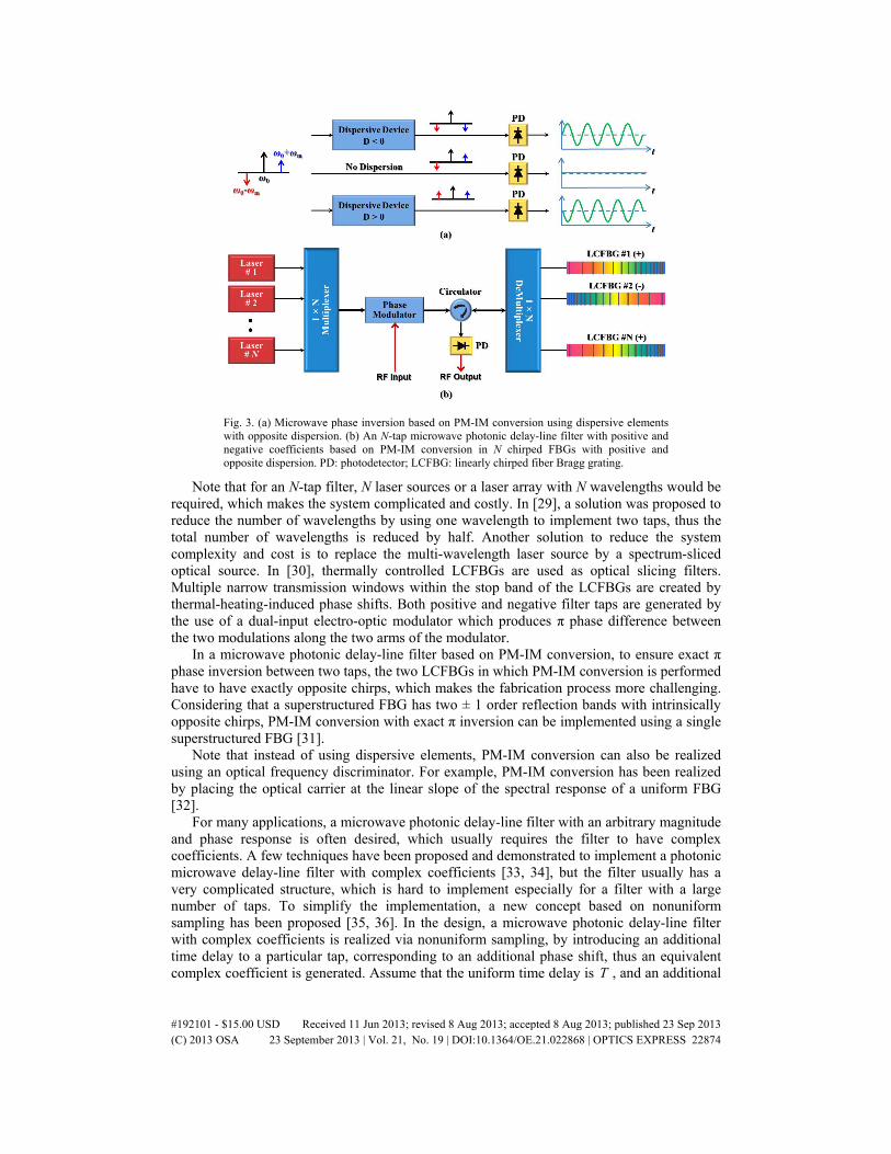
Fig. 3. (a) Microwave phase inversion based on PM-IM conversion using dispersive elements with opposite dispersion. (b) An N-tap microwave photonic delay-line filter with positive and negative coefficients based on PM-IM conversion in N chirped FBGs with positive and opposite dispersion. PD: photodetector; LCFBG: linearly chirped fiber Bragg grating.
Note that for an N-tap filter, N laser sources or a laser array with N wavelengths would be required, which makes the system complicated and costly. In [29], a solution was proposed to reduce the number of wavelengths by using one wavelength to implement two taps, thus the total number of wavelengths is reduced by half. Another solution to reduce the system complexity and cost is to replace the multi-wavelength laser source by a spectrum-sliced optical source. In [30], thermally controlled LCFBGs are used as optical slicing filters. Multiple narrow transmission windows within the stop band of the LCFBGs are created by thermal-heating-induced phase shifts. Both positive and negative filter taps are generated by the use of a dual-input electro-optic modulator which produces π phase difference between the two modulations along the two arms of the modulator.
In a microwave photonic delay-line filter based on PM-IM conversion, to ensure exact π phase inversion between two taps, the two LCFBGs in which PM-IM conversion is performed have to have exactly opposite chirps, which makes the fabrication process more challenging. Considering that a superstructured FBG has two ± 1 order reflection bands with intrinsically opposite chirps, PM-IM conversion with exact π inversion can be implemented using a single superstructured FBG [31].
Note that instead of using dispersive elements, PM-IM conversion can also be realized using an optical frequency discriminator. For example, PM-IM conversion has been realized by placing the optical carrier at the linear slope of the spectral response of a uniform FBG [32].
For many applications, a microwave photonic delay-line filter with an arbitrary magnitude and phase response is often desired, which usually requires the filter to have complex coefficients. A few techniques have been proposed and demonstrated to implement a photonic microwave delay-line filter with complex coefficients [33, 34], but the filter usually has a very complicated structure, which is hard to implement especially for a filter with a large number of taps. To simplify the implementation, a new concept based on nonuniform sampling has been proposed [35, 36]. In the design, a microwave photonic delay-line filter with complex coefficients is realized via nonuniform sampling, by introducing an additional time delay to a particular tap, corresponding to an additional phase shift, thus an equivalent complex coefficient is generated. Assume that the uniform time delay is T , and an additional
#192101 - $15.00 USD Received 11 Jun 2013; revised 8 Aug 2013; accepted 8 Aug 2013; published 23 Sep 2013(C) 2013 OSA 23 September 2013 | Vol. 21, No. 19 | DOI:10.1364/OE.21.022868 | OPTICS EXPRESS 22874
time delay kτΔ is introduced to the kth tap, the frequency response of the nonuniformly-
spaced microwave photonic delay-line filter at around the mth channel is then given by
( ) ( ) ( )1
0
exp exp .N
Non k kk
H jm j kTω α τ ω−
=
≈ − ΩΔ − (2)
As can be seen from Eq. (2), an equivalent phase shift of k kmϕ τ= ΩΔ is introduced to the
kth tap if an additional time delay of kτΔ is added to the tap. Based on this technique, a
microwave photonic delay-line filter with an arbitrary frequency response can be realized at the mth spectral channel by redesigning the time delays of the taps.
Fig. 4. Schematic diagram of a nonuniformly-spaced microwave photonic delay-line filter implemented using (a) a multi-wavelength laser source with nonuniformly spaced wavelengths, and (b) a spatially discrete chirped fiber Bragg grating (SD-CFBG).
Figure 4(a) shows a nonuniformly-spaced photonic microwave delay-line filter, which is implemented using a multi-wavelength laser source with nonuniformly spaced wavelengths [35]. The time delays of the taps are generated due to the chromatic dispersion in a dispersive element, which converts the nonuniformly-spaced wavelengths to nonuniformly spaced time delays. Since the actual tap coefficients are all positive, a simple implementation is achieved. The major limitation of the scheme in Fig. 4(a) is that the wavelengths must be precisely controlled, which may increase the system complexity and cost, especially for a filter in which a large number of taps are required. A simple solution is to replace the multi-wavelength laser source by a spectrum-sliced optical source. For example, we have demonstrated a nonuniformly spaced microwave photonic delay-line filter using a broadband optical source in which the spectrum slicing was performed using a spatially discrete chirped fiber Bragg grating (SD-CFBG) [37]. The SD-CFBG was fabricated using a regular linearly chirped phase mask by introducing axial spatial separation amongst multiple sub-gratings during the inscription process. In addition to the spectrum slicing function, the SD-CFBG also performs two other functions: to generate nonuniform time delays for the filter taps, and to tailor the coefficients of the taps. Figure 4(b) shows a microwave photonic delay-line filter based on an SD-CFBG. This technique offers a cost-effective and easy-to-implementation solution for nonuniformly-spaced microwave photonic delay-line filters with arbitrary frequency responses.
#192101 - $15.00 USD Received 11 Jun 2013; revised 8 Aug 2013; accepted 8 Aug 2013; published 23 Sep 2013(C) 2013 OSA 23 September 2013 | Vol. 21, No. 19 | DOI:10.1364/OE.21.022868 | OPTICS EXPRESS 22875
2.2 Optical spectral response to microwave spectral response conversion
A microwave photonic delay-line filter has a multi-tap structure with a finite impulse response. The total number of taps determines the filter frequency resolution. To achieve a high frequency resolution, a large number of taps (optical wavelengths) are needed. In addition, a finite impulse response filter has always a periodic spectral response. For many applications, however, we expect the filter has a single pass or stop band, which can be realized based on a different concept: optical filter response to microwave filter response conversion [38].
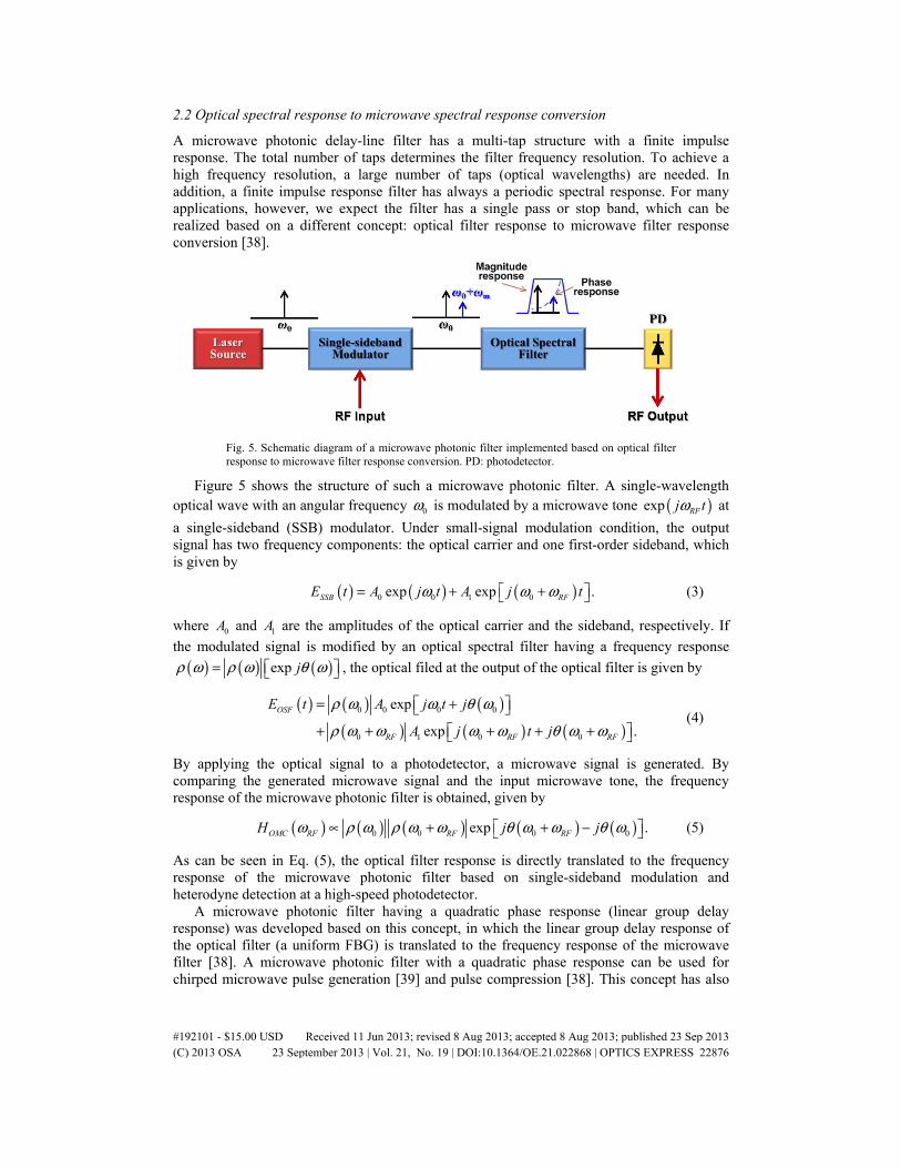
Fig. 5. Schematic diagram of a microwave photonic filter implemented based on optical filter response to microwave filter response conversion. PD: photodetector.
Figure 5 shows the structure of such a microwave photonic filter. A single-wavelength optical wave with an angular frequency 0ω is modulated by a microwave tone ( )exp RFj tω at
a single-sideband (SSB) modulator. Under small-signal modulation condition, the output signal has two frequency components: the optical carrier and one first-order sideband, which is given by
( ) ( ) ( )0 0 1 0exp exp .SSB RFE t A j t A j tω ω ω= + + (3)
where 0A and 1A are the amplitudes of the optical carrier and the sideband, respectively. If
the modulated signal is modified by an optical spectral filter having a frequency response
( ) ( ) ( )exp jρ ω ρ ω θ ω= , the optical filed at the output of the optical filter is given by
( ) ( ) ( )
( ) ( ) ( )0 0 0 0
0 1 0 0
exp
exp .
OSF
RF RF RF
E t A j t j
A j t j
ρ ω ω θ ω
ρ ω ω ω ω θ ω ω
= + + + + + +
(4)
By applying the optical signal to a photodetector, a microwave signal is generated. By comparing the generated microwave signal and the input microwave tone, the frequency response of the microwave photonic filter is obtained, given by
( ) ( ) ( ) ( ) ( )0 0 0 0exp .OMC RF RF RFH j jω ρ ω ρ ω ω θ ω ω θ ω∝ + + − (5)
As can be seen in Eq. (5), the optical filter response is directly translated to the frequency response of the microwave photonic filter based on single-sideband modulation and heterodyne detection at a high-speed photodetector.
A microwave photonic filter having a quadratic phase response (linear group delay response) was developed based on this concept, in which the linear group delay response of the optical filter (a uniform FBG) is translated to the frequency response of the microwave filter [38]. A microwave photonic filter with a quadratic phase response can be used for chirped microwave pulse generation [39] and pulse compression [38]. This concept has also
#192101 - $15.00 USD Received 11 Jun 2013; revised 8 Aug 2013; accepted 8 Aug 2013; published 23 Sep 2013(C) 2013 OSA 23 September 2013 | Vol. 21, No. 19 | DOI:10.1364/OE.21.022868 | OPTICS EXPRESS 22876
been employed to implement a microwave phase shifter [40]. An ideal microwave phase shifter is a special microwave filter with a unity magnitude response and a linear or nonlinear phase response. The optical filter response to microwave filter response conversion can be performed using a tilted fiber Bragg grating (TFBG) [40]. It is different from a regular FBG, where the variation of the refractive index is along the axis of the fiber core, a TFBG is made from the modulation of the refractive index which has a tilted angle to the axis of the optical fiber core. The tilt angle activates the mode coupling between the contra-propagating core mode and the cladding modes. Thus, the transmission spectrum of a TFBG contains a group of cladding-mode resonances with different depths. Based on the Kramers-Kronig relations, a change in amplitude leads to a change in phase. Therefore, a TFBG can act as an optical phase shifter to introduce a phase shift to a microwave signal. This is done by modulating the microwave signal on an optical carrier at a single-sideband modulator. By placing the carrier and the sideband at the notch of one resonance and the transmission band, respectively, a phase shift can be introduced between them. The detection of the optical signal at the output of the TFBG would generate a microwave signal with the phase shift translated directly to the microwave signal. The tuning of the phase shift can be performed by optically pumping the TFBG that is written in an Er/Yb co-doped fiber [41]. Due to the strong optical absorption in the Er/Yb co-doped fiber, the refractive index is changed when the fiber is optically pumped, thus the resonance wavelength is shifted, leading to the change of the phase shift. Since a TFBG has multiple resonances, and the phase shifts due to the multiple resonances follow a linear relationship, thus a TFBG can be employed to implement a tunable multi-tap microwave photonic delay-line filter with complex coefficients [42]. The frequency response can be continuously tunable by optically pumping the TFBG.
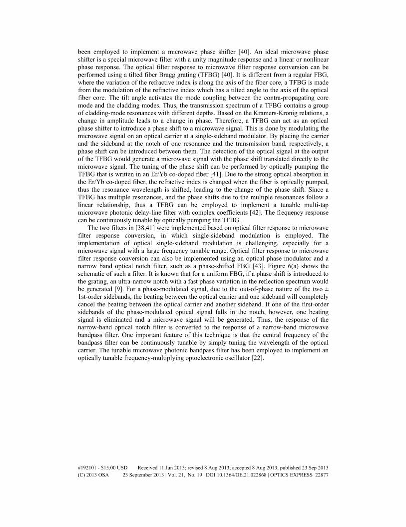
The two filters in [38,41] were implemented based on optical filter response to microwave filter response conversion, in which single-sideband modulation is employed. The implementation of optical single-sideband modulation is challenging, especially for a microwave signal with a large frequency tunable range. Optical filter response to microwave filter response conversion can also be implemented using an optical phase modulator and a narrow band optical notch filter, such as a phase-shifted FBG [43]. Figure 6(a) shows the schematic of such a filter. It is known that for a uniform FBG, if a phase shift is introduced to the grating, an ultra-narrow notch with a fast phase variation in the reflection spectrum would be generated [9]. For a phase-modulated signal, due to the out-of-phase nature of the two ± 1st-order sidebands, the beating between the optical carrier and one sideband will completely cancel the beating between the optical carrier and another sideband. If one of the first-order sidebands of the phase-modulated optical signal falls in the notch, however, one beating signal is eliminated and a microwave signal will be generated. Thus, the response of the narrow-band optical notch filter is converted to the response of a narrow-band microwave bandpass filter. One important feature of this technique is that the central frequency of the bandpass filter can be continuously tunable by simply tuning the wavelength of the optical carrier. The tunable microwave photonic bandpass filter has been employed to implement an optically tunable frequency-multiplying optoelectronic oscillator [22].
#192101 - $15.00 USD Received 11 Jun 2013; revised 8 Aug 2013; accepted 8 Aug 2013; published 23 Sep 2013(C) 2013 OSA 23 September 2013 | Vol. 21, No. 19 | DOI:10.1364/OE.21.022868 | OPTICS EXPRESS 22877
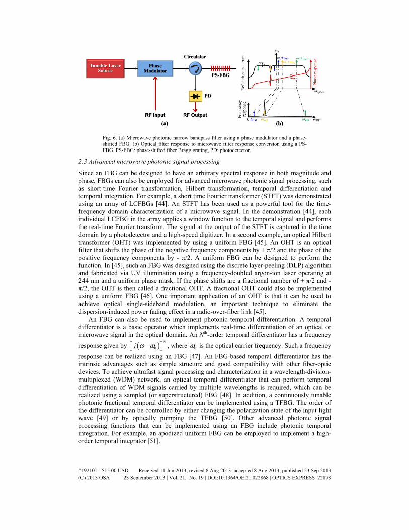
Fig. 6. (a) Microwave photonic narrow bandpass filter using a phase modulator and a phase-shifted FBG. (b) Optical filter response to microwave filter response conversion using a PS-FBG. PS-FBG: phase-shifted fiber Bragg grating, PD: photodetector.
2.3 Advanced microwave photonic signal processing
Since an FBG can be designed to have an arbitrary spectral response in both magnitude and phase, FBGs can also be employed for advanced microwave photonic signal processing, such as short-time Fourier transformation, Hilbert transformation, temporal differentiation and temporal integration. For example, a short time Fourier transformer (STFT) was demonstrated using an array of LCFBGs [44]. An STFT has been used as a powerful tool for the time-frequency domain characterization of a microwave signal. In the demonstration [44], each individual LCFBG in the array applies a window function to the temporal signal and performs the real-time Fourier transform. The signal at the output of the STFT is captured in the time domain by a photodetector and a high-speed digitizer. In a second example, an optical Hilbert transformer (OHT) was implemented by using a uniform FBG [45]. An OHT is an optical filter that shifts the phase of the negative frequency components by + π/2 and the phase of the positive frequency components by - π/2. A uniform FBG can be designed to perform the function. In [45], such an FBG was designed using the discrete layer-peeling (DLP) algorithm and fabricated via UV illumination using a frequency-doubled argon-ion laser operating at 244 nm and a uniform phase mask. If the phase shifts are a fractional number of + π/2 and - π/2, the OHT is then called a fractional OHT. A fractional OHT could also be implemented using a uniform FBG [46]. One important application of an OHT is that it can be used to achieve optical single-sideband modulation, an important technique to eliminate the dispersion-induced power fading effect in a radio-over-fiber link [45].
An FBG can also be used to implement photonic temporal differentiation. A temporal differentiator is a basic operator which implements real-time differentiation of an optical or microwave signal in the optical domain. An Nth-order temporal differentiator has a frequency
response given by ( )0
Nj ω ω− , where 0ω is the optical carrier frequency. Such a frequency
response can be realized using an FBG [47]. An FBG-based temporal differentiator has the intrinsic advantages such as simple structure and good compatibility with other fiber-optic devices. To achieve ultrafast signal processing and characterization in a wavelength-division-multiplexed (WDM) network, an optical temporal differentiator that can perform temporal differentiation of WDM signals carried by multiple wavelengths is required, which can be realized using a sampled (or superstructured) FBG [48]. In addition, a continuously tunable photonic fractional temporal differentiator can be implemented using a TFBG. The order of the differentiator can be controlled by either changing the polarization state of the input light wave [49] or by optically pumping the TFBG [50]. Other advanced photonic signal processing functions that can be implemented using an FBG include photonic temporal integration. For example, an apodized uniform FBG can be employed to implement a high-order temporal integrator [51].
#192101 - $15.00 USD Received 11 Jun 2013; revised 8 Aug 2013; accepted 8 Aug 2013; published 23 Sep 2013(C) 2013 OSA 23 September 2013 | Vol. 21, No. 19 | DOI:10.1364/OE.21.022868 | OPTICS EXPRESS 22878
3. FBGs for microwave arbitrary waveform generation
Microwave arbitrary waveforms are widely used in radar, wireless communications, medical imaging, and modern instrumentation systems. Thanks to the advantages such as high speed and broad bandwidth provided by optics, various photonically assisted techniques have been developed to generate high-frequency and large-bandwidth microwave arbitrary waveforms which may not be able or are difficult to generate by digital electronics [23].
FBGs have been widely employed for photonic microwave arbitrary waveform generation, due to its flexible spectral characteristics. Here two major techniques to generate microwave arbitrary waveforms in the optical domain using FBGs are discussed, 1) optical spectral shaping and frequency-to-time mapping (OSS-FTM), and 2) temporal pulse shaping (TPS).
Fig. 7. (a) Schematic diagram to show the principle of frequency-to-time mapping in a dispersive device. (b) Photonic microwave arbitrary waveform generation based on optical spectral shaping and dispersion-induced frequency-to-time mapping. (Color is for illustration purpose only.) PD: photodetector.
3.1 Spectral shaping and frequency-to-time mapping
A microwave arbitrary waveform can be generated based on optical spectral shaping (OSS) of an ultrashort optical pulse and frequency-to-time mapping (FTM) in a dispersive element. Figure 7(a) illustrates the principle of the frequency-to-time mapping process. The dispersive device can be a length of dispersive fiber or an LCFBG. If a transform-limited pulse ( )g t
with a temporal pulse width of 0tΔ is sent to the dispersive device with a value of dispersion
of 0Φ , the optical pulse is then stretched in time. If the temporal Fraunhofer condition 2
0 0 1tΦ Δ >> is satisfied, the optical field at the output of the dispersive device is given by
[52],
( ) ( )2
0 0
exp exp .2
t ty t j g j dτ τ τ
+∞
−∞
≈ − Φ Φ
(6)
Therefore, the intensity of the output signal is approximately the Fourier transform of the input signal envelope, which indicates that the pulse spectrum is mapped into a temporal waveform in real time, with the mapping relation given by 0tω = Φ . Therefore, the
frequency-to-time mapping process is also known as real-time Fourier transformation [52]. Figure 7(b) shows a microwave arbitrary waveform generation system based on OSS-FTM.
#192101 - $15.00 USD Received 11 Jun 2013; revised 8 Aug 2013; accepted 8 Aug 2013; published 23 Sep 2013(C) 2013 OSA 23 September 2013 | Vol. 21, No. 19 | DOI:10.1364/OE.21.022868 | OPTICS EXPRESS 22879
The system consists of a pulsed laser source, an optical spectral shaper and a dispersive element. The spectral shaper is used to shape the spectrum of the broadband optical pulse. After the frequency-to-time mapping process in the dispersive device, a microwave waveform having an envelope that is a scaled version of the shaped optical power spectrum is generated.
The main effort in this approach is to design an optical spectral shaper that has a magnitude response corresponding to the shape of the microwave waveform to be generated. An optical spectral shaper can be implemented based on free-space optics, such as a spatial light modulator (SLM) based spectral shaper [53, 54]. The key advantage of using an SLM for spectral shaping is the real-time updatability of the SLM. The free-space optics based technique, however, has the difficulties of complicated alignment and high coupling loss. On the other hand, an optical spectral shaper can also be implemented using pure fiber-optic devices. Compared with a free-space optics based solution, a fiber-optics based approach has the advantages of lower loss, better stability, and lower cost. Since the spectral characteristics of an FBG can be controlled, it can be employed as an all-fiber optical spectral shaper. Various configurations employing an FBG-based optical spectral shaper have been investigated. For example, the joint use of two uniform FBGs with one in transmission and the other in reflection could form an optical spectral shaper with a spectral response corresponding to a UWB monocycle or doublet pulse. After linear frequency-to-time mapping, a temporal UWB monocyle or doublet pulse is generated [55]. The frequency-to-time mapping is realized in a length of fiber, thus the optical fiber does not only serve as a dispersive element to accomplish the mapping process, but also distribute the UWB pulse to a remote site. UWB pulses can find wide applications in short-range high-data-rate wireless communications [56].
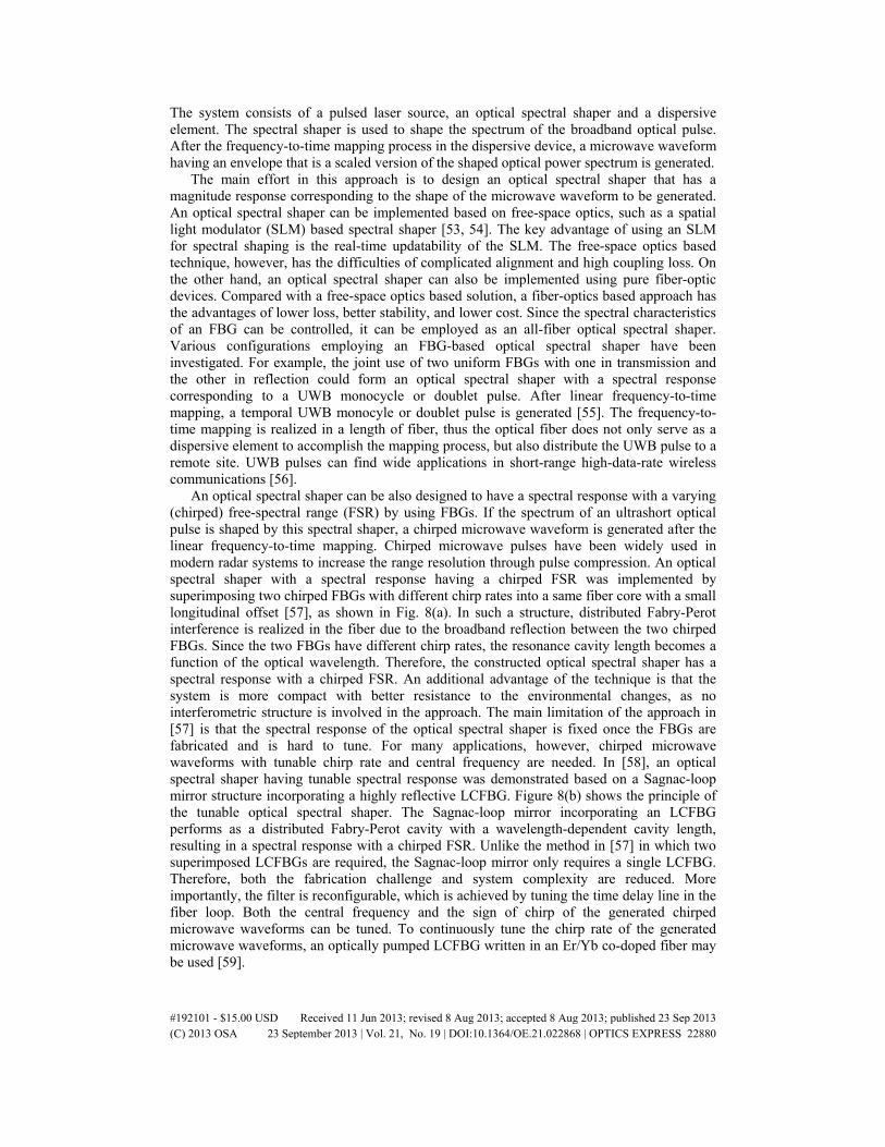
An optical spectral shaper can be also designed to have a spectral response with a varying (chirped) free-spectral range (FSR) by using FBGs. If the spectrum of an ultrashort optical pulse is shaped by this spectral shaper, a chirped microwave waveform is generated after the linear frequency-to-time mapping. Chirped microwave pulses have been widely used in modern radar systems to increase the range resolution through pulse compression. An optical spectral shaper with a spectral response having a chirped FSR was implemented by superimposing two chirped FBGs with different chirp rates into a same fiber core with a small longitudinal offset [57], as shown in Fig. 8(a). In such a structure, distributed Fabry-Perot interference is realized in the fiber due to the broadband reflection between the two chirped FBGs. Since the two FBGs have different chirp rates, the resonance cavity length becomes a function of the optical wavelength. Therefore, the constructed optical spectral shaper has a spectral response with a chirped FSR. An additional advantage of the technique is that the system is more compact with better resistance to the environmental changes, as no interferometric structure is involved in the approach. The main limitation of the approach in [57] is that the spectral response of the optical spectral shaper is fixed once the FBGs are fabricated and is hard to tune. For many applications, however, chirped microwave waveforms with tunable chirp rate and central frequency are needed. In [58], an optical spectral shaper having tunable spectral response was demonstrated based on a Sagnac-loop mirror structure incorporating a highly reflective LCFBG. Figure 8(b) shows the principle of the tunable optical spectral shaper. The Sagnac-loop mirror incorporating an LCFBG performs as a distributed Fabry-Perot cavity with a wavelength-dependent cavity length, resulting in a spectral response with a chirped FSR. Unlike the method in [57] in which two superimposed LCFBGs are required, the Sagnac-loop mirror only requires a single LCFBG. Therefore, both the fabrication challenge and system complexity are reduced. More importantly, the filter is reconfigurable, which is achieved by tuning the time delay line in the fiber loop. Both the central frequency and the sign of chirp of the generated chirped microwave waveforms can be tuned. To continuously tune the chirp rate of the generated microwave waveforms, an optically pumped LCFBG written in an Er/Yb co-doped fiber may be used [59].
#192101 - $15.00 USD Received 11 Jun 2013; revised 8 Aug 2013; accepted 8 Aug 2013; published 23 Sep 2013(C) 2013 OSA 23 September 2013 | Vol. 21, No. 19 | DOI:10.1364/OE.21.022868 | OPTICS EXPRESS 22880
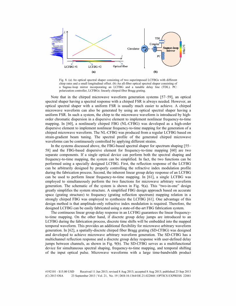
Fig. 8. (a) An optical spectral shaper consisting of two superimposed LCFBGs with different chirp rates and a small longitudinal offset. (b) An all-fiber optical spectral shaper consisting of a Sagnac-loop mirror incorporating an LCFBG and a tunable delay line (TDL). PC: polarization controller, LCFBGs: linearly chirped fiber Bragg grating.
Note that in the chirped microwave waveform generation systems [57–59], an optical spectral shaper having a spectral response with a chirped FSR is always needed. However, an optical spectral shaper with a uniform FSR is usually much easier to achieve. A chirped microwave waveform can also be generated by using an optical spectral shaper having a uniform FSR. In such a system, the chirp to the microwave waveform is introduced by high-order chromatic dispersion in a dispersive element to implement nonlinear frequency-to-time mapping. In [60], a nonlinearly chirped FBG (NL-CFBG) was developed as a high-order dispersive element to implement nonlinear frequency-to-time mapping for the generation of a chirped microwave waveform. The NL-CFBG was produced from a regular LCFBG based on strain-gradient beam tuning. The spectral profile of the generated chirped microwave waveforms can be continuously controlled by applying different strains.
In the systems discussed above, the FBG-based spectral shaper for spectrum shaping [55–58] and the FBG-based dispersive element for frequency-to-time mapping [60] are two separate components. If a single optical device can perform both the spectral shaping and frequency-to-time mapping, the system can be simplified. In fact, the two functions can be performed using a specially designed LCFBG. First, the reflection response of the LCFBG can be arbitrarily designed by properly controlling the refractive index modulation profile during the fabrication process. Second, the inherent linear group delay response of an LCFBG can be used to perform linear frequency-to-time mapping. In [61], a single LCFBG was employed to simultaneously perform the two functions for microwave arbitrary waveform generation. The schematic of the system is shown in Fig. 9(a). This “two-in-one” design greatly simplifies the system structure. A simplified FBG design approach based on accurate space (grating structure) to frequency (grating reflection spectrum) mapping relation in a strongly chirped FBG was employed to synthesize the LCFBG [61]. One advantage of this design method is that amplitude-only refractive index modulation is required. Therefore, the designed LCFBG can be easily fabricated using a state-of-the-art FBG fabrication system.
The continuous linear group delay response in an LCFBG guarantees the linear frequency-to-time mapping. On the other hand, if discrete group delay jumps are introduced to an LCFBG during the fabrication process, discrete time shifts will be embedded into the mapped temporal waveform. This provides an additional flexibility for microwave arbitrary waveform generation. In [62], a spatially-discrete chirped fiber Bragg grating (SD-CFBG) was designed and developed to achieve microwave arbitrary waveform generation. The SD-CFBG has a multichannel reflection response and a discrete group delay response with user-defined delay jumps between channels, as shown in Fig. 9(b). The SD-CFBG serves as a multifunctional device for simultaneous spectral shaping, frequency-to-time mapping, and temporal shifting of the input optical pulse. Microwave waveforms with a large time-bandwidth product
#192101 - $15.00 USD Received 11 Jun 2013; revised 8 Aug 2013; accepted 8 Aug 2013; published 23 Sep 2013(C) 2013 OSA 23 September 2013 | Vol. 21, No. 19 | DOI:10.1364/OE.21.022868 | OPTICS EXPRESS 22881
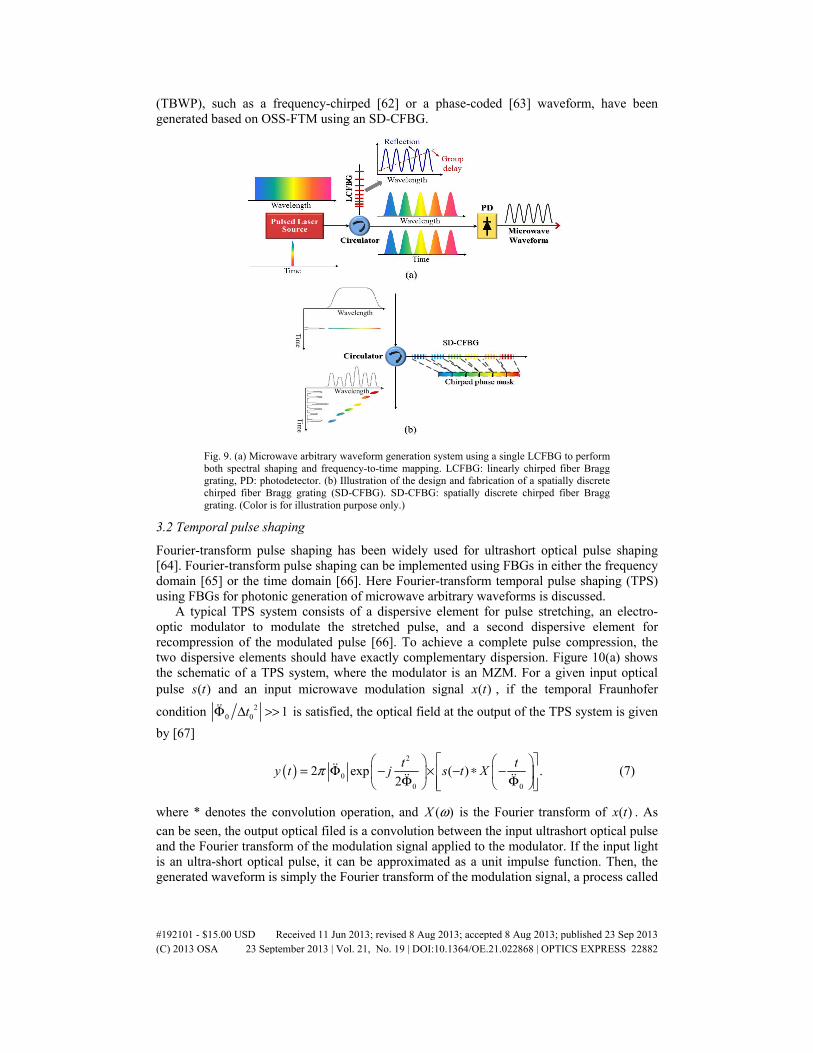
(TBWP), such as a frequency-chirped [62] or a phase-coded [63] waveform, have been generated based on OSS-FTM using an SD-CFBG.
Fig. 9. (a) Microwave arbitrary waveform generation system using a single LCFBG to perform both spectral shaping and frequency-to-time mapping. LCFBG: linearly chirped fiber Bragg grating, PD: photodetector. (b) Illustration of the design and fabrication of a spatially discrete chirped fiber Bragg grating (SD-CFBG). SD-CFBG: spatially discrete chirped fiber Bragg grating. (Color is for illustration purpose only.)
3.2 Temporal pulse shaping
Fourier-transform pulse shaping has been widely used for ultrashort optical pulse shaping [64]. Fourier-transform pulse shaping can be implemented using FBGs in either the frequency domain [65] or the time domain [66]. Here Fourier-transform temporal pulse shaping (TPS) using FBGs for photonic generation of microwave arbitrary waveforms is discussed.
A typical TPS system consists of a dispersive element for pulse stretching, an electro-optic modulator to modulate the stretched pulse, and a second dispersive element for recompression of the modulated pulse [66]. To achieve a complete pulse compression, the two dispersive elements should have exactly complementary dispersion. Figure 10(a) shows the schematic of a TPS system, where the modulator is an MZM. For a given input optical pulse ( )s t and an input microwave modulation signal ( )x t , if the temporal Fraunhofer
condition 20 0 1tΦ Δ >> is satisfied, the optical field at the output of the TPS system is given
by [67]
( )2
00 0
2 exp ( ) .2
t ty t j s t Xπ
= Φ − × − ∗ − Φ Φ
(7)
where * denotes the convolution operation, and ( )X ω is the Fourier transform of ( )x t . As
can be seen, the output optical filed is a convolution between the input ultrashort optical pulse and the Fourier transform of the modulation signal applied to the modulator. If the input light is an ultra-short optical pulse, it can be approximated as a unit impulse function. Then, the generated waveform is simply the Fourier transform of the modulation signal, a process called
#192101 - $15.00 USD Received 11 Jun 2013; revised 8 Aug 2013; accepted 8 Aug 2013; published 23 Sep 2013(C) 2013 OSA 23 September 2013 | Vol. 21, No. 19 | DOI:10.1364/OE.21.022868 | OPTICS EXPRESS 22882
real-time Fourier transformation. Generation of an optical waveform based on Fourier transform optical pulse shaping using a TPS system has been experimentally investigated based on amplitude-only modulation [68]. The key advantage of the TPS technique is that an ultra-fast optical waveform can be generated using a relatively slow microwave drive signal.
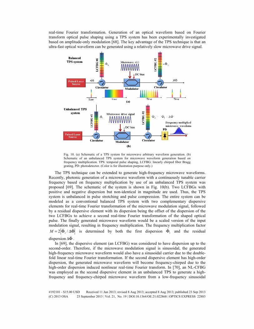
Fig. 10. (a) Schematic of a TPS system for microwave arbitrary waveform generation. (b) Schematic of an unbalanced TPS system for microwave waveform generation based on frequency multiplication. TPS: temporal pulse shaping, LCFBG: linearly chirped fiber Bragg grating, PD: photodetector. (Color is for illustration purpose only.)
The TPS technique can be extended to generate high-frequency microwave waveforms. Recently, photonic generation of a microwave waveform with a continuously tunable carrier frequency based on frequency multiplication by use of an unbalanced TPS system was proposed [69]. The schematic of the system is shown in Fig. 10(b). Two LCFBGs with positive and negative dispersion but non-identical in magnitude are used. Thus, the TPS system is unbalanced in pulse stretching and pulse compression. The entire system can be modeled as a conventional balanced TPS system with two complementary dispersive elements for real-time Fourier transformation of the microwave modulation signal, followed by a residual dispersive element with its dispersion being the offset of the dispersion of the two LCFBGs to achieve a second real-time Fourier transformation of the shaped optical pulse. The finally generated microwave waveform would be a scaled version of the input modulation signal, resulting in frequency multiplication. The frequency multiplication factor
12 /M = Φ ΔΦ is determined by both the first dispersion 1Φ and the residual
dispersion ΔΦ . In [69], the dispersive element (an LCFBG) was considered to have dispersion up to the
second-order. Therefore, if the microwave modulation signal is sinusoidal, the generated high-frequency microwave waveform would also have a sinusoidal carrier due to the double-fold linear real-time Fourier transformation. If the second dispersive element has high-order dispersion, the generated microwave waveform will become frequency-chirped due to the high-order dispersion induced nonlinear real-time Fourier transform. In [70], an NL-CFBG was employed as the second dispersive element in an unbalanced TPS to generate a high-frequency and frequency-chirped microwave waveform from a low-frequency sinusoidal
#192101 - $15.00 USD Received 11 Jun 2013; revised 8 Aug 2013; accepted 8 Aug 2013; published 23 Sep 2013(C) 2013 OSA 23 September 2013 | Vol. 21, No. 19 | DOI:10.1364/OE.21.022868 | OPTICS EXPRESS 22883
microwave drive signal. Moreover, if the two LCFBGs are written in Er/Yb co-doped fibers, the dispersion of the FBGs can be continuously tuned through optical pumping. When the optically pumped LCFBGs are incorporated in the unbalanced TPS system, photonic generation of a frequency tunable microwave waveform can be achieved [71].
4. Summary
FBGs and their applications for microwave photonic signal processing and photonic generation of microwave arbitrary waveforms have been discussed. In general, an FBG in a microwave photonic subsystem can serve as 1) a time-delay device; 2) a narrow-band optical filter; 3) a dispersive element; and 4) a broadband optical spectral shaper. The key advantages of using FBGs for microwave photonics applications include small size, low loss, low cost, and high compatibility with other well-developed fiber-optic devices.
Compared with microwave photonics systems based on free-space optics, FBG-based systems have the limitation of poor reconfigurability since the spectral response of an FBG can be hardly changed once fabricated. The techniques for FBG tuning are mainly based on mechanical [72] and thermal tuning [41], at a very low tuning speed. An improved tuning speed can be achieved with the use of a piezoelectric device [73] or a divided thin-film heater [74]. Further improvement in tuning speed can be achieved by electrical [75] or magnetic [76] tuning.
While FBG devices are cheap, microwave photonics systems based on fiber-optic devices are still costly due to the use of discrete optical devices, such as high-speed electro-optical modulators and photodetectors. A solution to reduce the system cost, weight, footprint size and power consumption is to use photonic integrated circuits (PICs) [77]. Investigation of on-chip microwave photonics subsystems using the PIC technique would be a future research direction in this field. Bragg gratings with the desired spectral characteristics can be incorporated in an on-chip microwave photonics system by writing waveguide Bragg gratings. Research attempts to develop waveguide Bragg gratings have been reported [78–80]. For instance, photonic time delay lines have been implemented using integrated Bragg gratings in silicon-on-insulator (SOI) rib waveguides, which can be tuned by either electrical [78] or thermal [79] tuning. Waveguide Bragg gratings have also been demonstrated for photonic signal processing, such as ultrafast all-optical temporal differentiation [80].
Acknowledgments
This work was supported by the Natural Sciences and Engineering Research Council of Canada (NSERC). Chao Wang was supported by NSERC through the Vanier Canada Graduate Scholarship program and the NSERC Postdoctoral Fellowship program.
#192101 - $15.00 USD Received 11 Jun 2013; revised 8 Aug 2013; accepted 8 Aug 2013; published 23 Sep 2013(C) 2013 OSA 23 September 2013 | Vol. 21, No. 19 | DOI:10.1364/OE.21.022868 | OPTICS EXPRESS 22884


