
Characterizing the Microstructure of a Corrosion-Resistant Alloy

1
Microstructure, Mechanical Properties and Corrosion Resistance of Nanocomposite Coatings Deposited by PVD Technology
Krzysztof Lukaszkowicz1, Leszek A. Dobrzański1 and Jozef Sondor2
1Silesian University of Technology, 2LISS a.s.,
1Poland 2Czech Republic
1. Introduction
The research issues concerning the production of coatings are the most important directions of surface engineering development, ensuring the obtainment of coatings of high usable properties in the scope of mechanical characteristics and corrosion resistance (Yu et al., 2009; Cheng et al., 2009; Kao, 2009; Mao et al., 2009; Sundararajan et al., 2009). Giving new operating characteristics to commonly known materials is frequently obtained by laying simple monolayer, multilayer or gradient coatings using PVD methods (Dobrzanski et al.,2005; Lukaszkowicz & Dobrzański, 2008). While selecting the coating material, we encounter a barrier caused by the fact that numerous properties expected from an ideal coating are impossible to be obtained simultaneously. For example, an increase in hardness and strength causes the reduction of the coating’s ductility and adherence to the substrate. The application of the nanostructure coatings is seen as the solution of this issue (Voevodin et al., 2005; Yang et al., 2007). According to the Hall–Petch equation, the strength properties of the material rise along with the reduction of the grain size. In case of the coatings deposited in the PVD processes, the structures obtained with grain size ~10 nm cause the obtainment of the maximum mechanical properties. Coatings of such structure present very high hardness >40 GPa, ductility, stability in high temperatures, etc. (Tjong & Chen, 2004; Zhang et al., 2007; Veprek et al., 2005). The known dependency between the hardness and abrasion resistance became the foundation for the development of harder and harder coating materials. The progress in the field of producing coatings in the physical vapour deposition process enables the obtainment of coatings of nanocrystal structure presenting high mechanical and usable properties. The coatings of such structure are able to maintain a low friction coefficient (self-lubricating coatings) in numerous working environments, maintaining high hardness and increased resistance (Donnet & Erdemir, 2004; Voevodin & Zabinski, 2005). The main concept in the achievement of high hardness of nanostructure coatings and good mechanical properties and high strength related to it, particularly in case of nanocomposite coatings (Holubar et al., 2000; Rafaja et al., 2007; Carvalho et al., 2004), is the restriction of
www.intechopen.com

Advances in Diverse Industrial Applications of Nanocomposites
2
the rise and the movement of dislocations. High hardness and strength of the nanocomposite coatings are due to the fact that the movement of dislocations is suppressed at small grains and in the spaces between them, which causes the appearance of incoherent deformations. When the grain size is reduced to that of nanometres, the activity of dislocations as the source of the material ductility is restricted. This type of coatings is also characterized with a large number of grain boundaries with a crystalline/amorphous transition across grain–matrix interfaces, restricting the rise and development of cracks. Such mechanism explains the resistance to fragile cracking of nanocomposite coatings (Veprek, 1997; Veprek, 1998; Rafaja et al., 2006). Simultaneously, the equiaxial grain shapes, high angle grain boundaries, low surface energy and the presence of the amorphous boundary phase facilitating the slide along the grain boundaries cause a high plasticity of the nanocomposite coatings (Voevodin et al., 2005). Nanocomposite coatings comprise at least two phases, a nanocrystalline phase and a matrix phase, where the matrix can be either nanocrystalline or amorphous phase. Various analyses revealed that the synthesized TiAlSiN coatings exhibited nanostructured composite microstructures consisting of solid-solution (Ti,Al,Si)N crystallites and amorphous Si3N4. The Si addition caused the grain refinement of (Ti,Al,Si)N crystallites and its uniform distribution with percolation phenomenon of amorphous silicon nitride (Zhang & Ali, 2007; Holubar et al., 2000; Rafaja et al., 2007; Carvalho et al., 2004). One of the general reasons for depositing by PVD techniques is that protective coatings deposited by PVD tend to have higher corrosion resistance than the substrate material. Ceramic hard coatings increase the life of the coated components, not only due to the protection against aggressive environments, but also during operation involving mechanical contact with abrasive surfaces. This effect results of high hardness resulting from the smaller grain size of the coatings’ structure.
2. Experimental procedures
The tests were made on samples of the X40CrMoV5-1 hot work tool steel and the X6CrNiMoTi17-12-2 austenitic stainless steel, deposited by PVD process with TiAlSiN, CrAlSiN, AlTiCrN hard coatings. The coating deposition process was made in a device based on the cathodic arc evaporation method in an Ar and N2 atmosphere. Cathodes containing pure metals (Cr, Ti) and the AlSi (88:12 wt%) alloy were used for deposition of the coatings. The base pressure was 5 × 10⁻⁶ mbar, the deposition temperature was 500 ºC. The deposition conditions are summarized in Table 1.
Coating Substrate bias voltage
[V] Arc current source
[A] Pressure
[Pa]
TiAlSiN -90 Ti – 80
AlSi – 120 2,0
CrAlSiN -60 Cr – 70
AlSi – 120 3,0
AlTiCrN -60 Cr – 70
AlTi – 120 2,0
Table 1. Deposition parameters of the coatings.
www.intechopen.com
Microstructure, Mechanical Properties and Corrosion Resistance of Nanocomposite Coatings Deposited by PVD Technology
3
Diffraction and thin film structure were tested with the use of the JEOL JEM 3010 UHR transmission electron microscope, at 300 kV bias voltage. Observations of surface and structures of the deposited coatings were carried out on cross sections in the SUPRA 25 scanning electron microscope. Detection of secondary electron was used for generation of fracture images with 15 kV bias voltage. Phase identification of the investigated coatings was performed by glancing angle X-ray diffraction (GAXRD). The cross-sectional atomic composition of the samples (coating and substrate) was obtained by using a glow discharge optical spectrometer, GDOS-750 QDP from Leco Instruments. The following operation conditions of the spectrometer Grimm lamp were fixed during the tests:
• lamp inner diameter – 4 mm;
• lamp supply voltage – 700 V;
• lamp current – 20 mA;
• working pressure – 100 Pa. Tests of the coatings’ adhesion to the substrate material were made using the scratch test on the CSEM REVETEST device. The tests were made using the following parameters:
• load range 0–100 N,
• load increase rate (dL/dt): 100 N/min,
• indenter’s sliding speed (dx/dt): 10 mm/min,
• acoustic emission detector’s sensitivity AE: 1. The critical load LC, causing the loss of the coating adhesion to the material, was determined
on the basis of the values of the acoustic emission, AE, and friction force, Ft and observation
of the damage (Burnett & Rickerby, 1987; Bellido-Gonzalez et al., 1995) developed in the
track using a LEICA MEF4A optical microscope.
The microhardness tests of coatings were made with the SHIMADZU DUH 202 ultra-
microhardness tester. The test conditions were selected in order as to be comparable for all
coatings. Measurements were made with 50 mN load, to eliminate the substrate influence on
the coating hardness.
The thickness of coatings was determined using the ‘‘kalotest’’ method, i.e. measuring the
characteristics of the spherical cap crater developed on the surface of the coated specimen
tested (Holmberg & Matthews, 1994).
The X-ray line broadening technique was used to determine crystallite size of the coatings
using Scherrer formula (Behera et al., 2004) with silicon as internal standard.
Investigation of the electrochemical corrosion behaviour of the samples was done in a PGP
201 Potentiostat/Galvanostat, using a conventional three-electrode cell consisting of a
saturated calomel reference electrode (SCE), a platinum counter electrode and the studied
specimens as the working electrode. To simulate the aggressive media, 1-M HCl solution
was used under aerated conditions and room temperature. The aqueous corrosion
behaviour of the coatings was studied first by measuring the open circuit potential (OCP)
for 1 h. Subsequently, a potentiodynamic polarization curve has been recorded. The curve
started at a potential of ~100 mV below the corrosion potential and ended at +1200 mV or a
threshold intensity level set at 100 mA/cm2. Once this level was reached, the reverse cycle
was started. The scan rate was 15 mV/min. The corrosion current densities and the
polarization resistance were obtained on the basis of the Tafel analysis after
potentiodynamic polarization measurements.
www.intechopen.com

Advances in Diverse Industrial Applications of Nanocomposites
4
3. Results and discussion
The coatings present a compact structure, without any visible delaminations or defects. The morphology of the fracture of coatings is characterized by a dense structure, in some cases there is a columnar structure (Figs. 1, 2, 3). The fracture surface of the steel samples was examined and the deposited coatings show a sharp transition zone between the substrate and the coating.
Fig. 1. Fracture of the TiAlSiN coating deposited onto the X40CrMoV5-1 steel substrate.
Fig. 2. Fracture of the CrAlSiN coating deposited onto the X40CrMoV5-1 steel substrate.
www.intechopen.com

Microstructure, Mechanical Properties and Corrosion Resistance of Nanocomposite Coatings Deposited by PVD Technology
5
Fig. 3. Fracture of the AlTiCrN coating deposited onto the X40CrMoV5-1 steel substrate.
Transmission electron microscopy (TEM) examination of the coatings showed that they consisted of fine crystallites (Fig. 4), and there was no suggestion of epitaxial growth. Single large grains were only observed in case of the TiAlSiN coating (Fig. 5), which may suggest the occurrence of the epitaxion phenomenon as the consequence of large crystallite occurrence in the coating.
Fig. 4. Structure of the thin foil from the CrAlSiN coating.
10 nm
www.intechopen.com

Advances in Diverse Industrial Applications of Nanocomposites
6
Based on the glancing angle X-ray diffraction (GAXRD) of the samples examined (Figs. 6, 7, 8), the occurrence of fcc phases was only observed in the coatings. The hexagonal AlN of wurtzite type was not discovered in the coatings examined, which could have been caused by a low amount of aluminium in the coatings. Based on the results obtained, using Scherer method, the size of crystallites in the coatings examined was determined. The results were presented in Table 2. The hardness of the coatings tested fits within the range from 40 to 42 GPa. The highest hardness was recorded in the case of the AlTiCrN coating (Table 2).
Critical load LC1 [N]
Critical load LC2 [N] Coating
Thickness [μm]
Microhardness [GPa]
Crystallite size [nm] AS HWTS AS HWTS
AlTiCrN 2.4 42 17 15 24 27 54
CrAlSiN 2.9 40 25 8 18 28 49
TiAlSiN 2.1 40 11 9 16 27 46
Table 2. The characteristics of the tested coatings (AS – austenitic steel, HWTS – hot work tool steel).
111
200
220
311
400
420
Fig. 5. Microstructure of the thin foil from the TiAlSiN coating, (a) light field, (b) dark field from the (111) reflex, (c) diffraction pattern from the area as in figure a, (d) solution of the diffraction pattern.
a b
c d
www.intechopen.com

Microstructure, Mechanical Properties and Corrosion Resistance of Nanocomposite Coatings Deposited by PVD Technology
7
0
500
1000
1500
2000
2500
3000
35 45 55 65 75 85 95 105
Reflection angle, 2θ
Inte
nsi
ty,
imp
/s
(Cr,
Al,
Si)
N (
11
1)
(Cr,
Al,
Si)
N (
20
0)
(Cr,
Al,
Si)
N (
22
0)
(Cr,
Al,
Si)
N (
31
1)
Fig. 6. GAXRD spectra of the CrAlSiN coating at glancing incidence angle α=2°.
200
400
600
800
1000
1200
35 45 55 65 75 85 95 105
Reflection angle, 2θ
Inte
nsi
ty,
imp
/s
(Al,
Ti,
Cr)
N (
11
1)
(Al,
Ti,
Cr)
N (
20
0)
(Al,
Ti,
Cr)
N (
22
0)
Fig. 7. GAXRD spectra of the AlTiCrN coating at glancing incidence angle α=2°.
200
400
600
800
1000
1200
1400
1600
35 45 55 65 75 85 95 105
Reflection angle, 2θ
Inte
nsi
ty,
imp
/s
(Ti,
Al,
Si)
N (
11
1)
(Ti,
Al,
Si)
N (
20
0)
(Ti,
Al,
Si)
N (
22
0)
(Ti,
Al,
Si)
N (
31
1)
(Ti,
Al,
Si)
N (
22
2)
Fig. 8. GAXRD spectra of the TiAlSiN coating at glancing incidence angle α=2°.
The critical load values LC1 and LC2 were determined by the scratch test method (Figs. 9, 10, 11). The load at which the first coating defects appear is known in the references (Sergici & Randall, 2006; He et al., 2006)) as the first critical load LC1. The first critical load LC1 corresponds to the point at which first damage is observed; the first appearance of
www.intechopen.com

Advances in Diverse Industrial Applications of Nanocomposites
8
microcraking, surface flaking outside or inside the track without any exposure of the substrate material-the first cohesion-related failure event (Figs. 12a, 13a, 14a). LC1 corresponds to the first small jump on the acoustic emission signal, as well as on the friction force curve (Figs. 9, 10, 11). The second critical load LC2 is the point at which complete delamination of the coatings starts; the first appearance of cracking, chipping, spallation and delamination outside or inside the track with the exposure of the substrate material—the first adhesion related failure event (Figs. 12b, 13b, 14b). After this point the acoustic emission graph and friction forces have a disturbed run (become noisier). The cumulative specification of the test results are presented in Table 2.
0
20
40
60
80
100
0 1 2 3 4 5 6 7 8 9
Path X, mm
Fri
ctio
n f
orc
e F
t, N
ggg
0
20
40
60
80
100
0 10 19 29 38 48 58 67 77 87 96
Load force Fn, N
Aco
ust
ic e
mis
sion
AE
n
n
Fig. 9. Diagram of the dependence of the acoustic emission (AE) and friction force Ft on the load for the X40CrMoV5-1 steel with the AlTiCrN coating.
0
20
40
60
80
100
0 1 2 3 4 5 6 7 8 9
Path X, mm
Fri
ctio
n f
orc
e F
t, N
gg
g
0
20
40
60
80
100
0 10 20 30 40 50 60 70 80 90 100
Load force Fn, N
Aco
ust
ic e
mis
sio
n A
E n
n
Fig. 10. Diagram of the dependence of the acoustic emission (AE) and friction force Ft on the load for the X40CrMoV5-1 steel with the CrAlSiN coating.
www.intechopen.com

Microstructure, Mechanical Properties and Corrosion Resistance of Nanocomposite Coatings Deposited by PVD Technology
9
0
20
40
60
80
100
0 1 2 3 4 5 6 7 8 9
Path X, mm
Fri
ctio
n f
orc
e F
t, N
ggg
0
20
40
60
80
100
0 10 20 30 40 50 60 70 80 90 100
Load force Fn, N
Aco
ust
ic e
mis
sion
AE
n
n
Fig. 11. Diagram of the dependence of the acoustic emission (AE) and friction force Ft on the load for the X40CrMoV5-1 steel with the TiAlSiN coating.
Fig. 12. Scratch failure pictures of the AlTiCrN coating on X40CrMoV5-1 steel substrate at: (a) LC1, (b) LC2.
50 μm
(a)
50 μm
(b)
www.intechopen.com

Advances in Diverse Industrial Applications of Nanocomposites
10
Fig. 13. Scratch failure pictures of the CrAlSiN coating on X40CrMoV5-1 steel substrate at: (a) LC1, (b) LC2.
To establish the nature of damage causing the increase in acoustic emission intensity, the examinations of the scratches that arose during the test were made with the use of the light microscope coupled with a measuring device, thus determining the value of the LC1 and LC2 critical load on the basis of metallographical observations. In case of the coatings examined, it was found that coating AlTiCrN had the highest critical load value LC1 = 24 N and LC2 = 54 N deposited on substrate made of the X40CrMoV5-1 steel, whereas CrAlSiN and TiAlSiN coatings deposited on the substrate made of the X6CrNiMoTi17-12-2 steel had the lowest value. In general, the coatings deposited on the substrate made of the X40CrMoV5-1 hot work tool steel show better adherence to the substrate than coatings deposited on the substrate made of the X6CrNiMoTi17-12-2 austenitic steel. This is caused by a significantly higher hardness of the X40CrMoV5-1 steel. The first symptoms of damage in most of the coatings examined are in the form of arch cracks caused by tension or scaling occurring on the bottom of the scratch that appears during the scratch test (Figs. 12, 13, 14). Occasionally, there are some small chippings on the scratch edges. Along with the load increase, semicircles are formed caused by conformal cracking, leading to delaminations and chippings, resulting in a local delamination of the coating. As a result of the steel fracture test against the coatings deposited, made after prior cooling in liquid nitrogen, no case delaminations were revealed along the substrate-coating separation surface, which indicates a good adhesion of coatings to substrate.
(a)
(b)
50 μm
50 μm
www.intechopen.com

Microstructure, Mechanical Properties and Corrosion Resistance of Nanocomposite Coatings Deposited by PVD Technology
11
Fig. 14. Scratch failure pictures of the TiAlSiN coating on X40CrMoV5-1 steel substrate at: (a) LC1, (b) LC2.
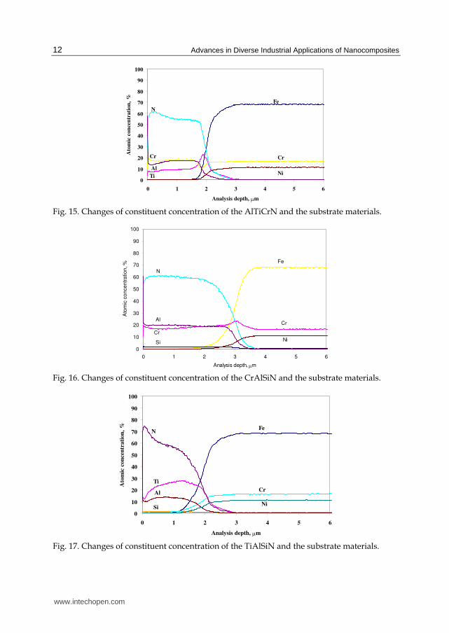
Changes of coating component concentration and substrate material made in GDOS were presented in Figs. 15, 16, and 17. The tests carried out with the use of GDOS indicate the occurrence of a transition zone between the substrate material and the coating, which results in the improved adhesion between the coatings and the substrate. In the transition zone between the coatings and the substrate, the concentration of the elements of the substrate increases with simultaneous rapid decrease in concentration of elements contained in the coatings. The existence of the transition zone should be connected with the increase in desorption of the substrate surface and the occurrence of defects in the substrate and the relocation of the elements within the connection zone as a result of a high energy ion reaction. Such results, however, cannot be interpreted explicitly, due to the non-homogeneous evaporation of the material from the sample surface. The corrosion resistance test results of coatings deposited on substrate made of the X6CrNiMoTi17-12-2 austenitic steel with the method of potentiodynamic polarization curves in 1-M HCl solution were presented in Fig. 18. It was found out, as a result of the electrochemical corrosion investigations, that the coatings deposited by PVD process onto the substrate made of the X6CrNiMoTi17- 12-2 steel may be an effective substrate material protection against corrosive agents. The potentiodynamic polarization curve analysis (Fig. 18) and that of the corrosion rate confirm the better corrosion resistance of the samples with
(b)
50 μm
50 μm
(a)
www.intechopen.com
Advances in Diverse Industrial Applications of Nanocomposites
12
0
10
20
30
40
50
60
70
80
90
100
0 1 2 3 4 5 6
Analysis depth, μm
Ato
mic
con
cen
trati
on
, %
N
Al
Fe
Cr
TiNi
Cr
Fig. 15. Changes of constituent concentration of the AlTiCrN and the substrate materials.
0
10
20
30
40
50
60
70
80
90
100
0 1 2 3 4 5 6
Analysis depth, μm
Ato
mic
co
nce
ntr
atio
n, %
Cr
Al
N
Fe
NiSi
Cr
Fig. 16. Changes of constituent concentration of the CrAlSiN and the substrate materials.
0
10
20
30
40
50
60
70
80
90
100
0 1 2 3 4 5 6
Analysis depth, μm
Ato
mic
con
cen
trati
on
, %
N
Ti
Al
Si
Fe
Cr
Ni
Fig. 17. Changes of constituent concentration of the TiAlSiN and the substrate materials.
www.intechopen.com

Microstructure, Mechanical Properties and Corrosion Resistance of Nanocomposite Coatings Deposited by PVD Technology
13
coatings layers than the uncovered sample (Table 3). During the anode scanning, the current density is always lower for the sample with a coating deposited on its surface in comparison to the uncovered sample (11.56 μA/cm2), which indicates a good protective effect. The potentiodynamic polarization curve course is the evidence of the active process of the uncoated X6CrNiMoTi17-12-2 steel surface. The lowest corrosion current density of the investigated coatings is obtained (from Tafel plot) for the CrAlSiN coating. This can be explained by the relatively low porosity of this coating. The current density for the other coatings is significantly higher than the one obtained for the CrAlSiN coating. The shape of the curves in the cathode range indicates the strong slowing down of reactions occurring on the coated samples. The behaviour of the systems tested within the anodic range may evidence the porosity or defect of the coatings. Some of the coatings tested within the anodic range were subjected to self-passivation; however, the passive state occurs within a narrow range of the potentials. The growth of the anodic current related to the transpassivation was observed within the 0–0.4 mV potential range. The corrosion current density and corrosion rate were estimated according to the potentiodynamic curve courses (Table 3). The corrosion potential Ecor test results confirm the better corrosive resistance of the coatings (Fig. 19) than the uncoated steel samples. The fact that the corrosive potential of the uncoated substrate significantly grows after a 60-min experiment is also worth noting.
-0,60
-0,40
-0,20
0,00
0,20
0,40
0,60
0,80
1,00
1,20
1,40
-10 -8 -6 -4 -2 0
Current density log |i|
Po
ten
tia
l, V
substrate
TiAlSiN
AlTiCrN
CrAlSiN
Fig. 18. Potentiodynamic polarization curves of the coatings in 1 M HCl solution.
-0,40
-0,35
-0,30
-0,25
-0,20
-0,15
-0,10
0 600 1200 1800 2400 3000 3600
Time, s
Po
ten
tia
l, V
CrAlSiN
AlTiCrN
substrate TiAlSiN
Fig. 19. Open circuit potential curves of the coatings in 1 M HCl solution.
www.intechopen.com

Advances in Diverse Industrial Applications of Nanocomposites
14
Coating type Current density icor,
[μA/cm2]
Corrosion potential Ecor, [mV]
Corrosion rate, [mm/year]
AlTiCrN 0,77 -0,26 9,0
CrAlSiN 0,15 -0,22 1,7
TiAlSiN 0,48 -0,28 5,6
Substrate 11,65 -0,30 136,2
Table 3. Summary results of the electrochemical corrosion investigation.
Changes of the coating colour and increase in their roughness caused by the intensive
dissolving of their surface were observed during the aggressive agent action. Microscope
observations make it possible to state that the coating damage process due to
electrochemical corrosion proceeds in double way. In the first case, the coating damage
develops in many places, whereas the area of these damages is small. In the second case,
however, the coating damage caused by the aggressive agent action comprises a big area,
leading to changes in its appearance or delamination of the coating parts from the substrate
material. The tests show pitting corrosive attacks.
4. Summary
The compact structure of the coatings without any visible delamination was observed in the
scanning electron microscope. The fracture morphology of the coatings tested is
characterized with a dense structure. Based on the thin film test in the transmission electron
microscope, it was observed that the coatings are built of fine crystallites. Their size is 11–25
nm.
The scratch tests on coating adhesion reveal the cohesive and adhesive properties of the
coatings deposited on the substrate material. In virtue of the tests carried out, it was found
that the critical load LC2 fitted within the range 46–54 N for the coatings deposited on a
substrate made of hot work tool steel X40CrMoV5-1 and 27–28 N for coatings deposited on
the substrate made of the X6CrNiMoTi17-12-2 austenitic steel. The coatings deposited on the
substrate made of the X40CrMoV5-1 steel present a better adhesion than the coatings
deposited on the substrate made of the X6CrNiMoTi17-12-2 steel. This is caused by a better
hardness of the X40CrMoV5-1 steel. The tests made with the use of GDOS indicate the
occurrence of a transition zone between the substrate material and the coating, which affects
the improved adhesion between the coatings and the substrate.
As a result of the potentiodynamic polarization curve analysis, the corrosion current
density–corrosion rate was determined. It confirms the better corrosion resistance of
samples coated with the use of the PVD technique to the uncoated samples made of the
austenitic steel (11.65 μA/cm2). The corrosion current density for the coatings tested fits
within the range 0.15–0.77 μA/cm2, which proves their good anticorrosion properties.
In order to evaluate with more detail the possibility of applying these surface layers in tools,
further investigations should be concentrated on the determination of the thermal fatigue
resistance of the coatings. The very good mechanical properties of the nanocomposite
coatings make them suitable in industrial applications. The investigation results will
provide useful information to applying the nanocomposite coatings for the improvement of
mechanical properties of the hot work tool steels.
www.intechopen.com

Microstructure, Mechanical Properties and Corrosion Resistance of Nanocomposite Coatings Deposited by PVD Technology
15
5. Acknowledgement
Research was financed partially within the framework of the Polish State Committee for Scientific Research Project No N N507 550738 headed by Dr Krzysztof Lukaszkowicz.
6. References
Behera, S.K.; Sahu, P.K.; Pratihar, S.K. & Bhattacharyya, S. (2004). Materials Letters, 58, 29, (November 2004) 3710-3715.
Bellido-Gonzalez, V.; Stefanopoulos, N. & Deguilhen, F. (1995). Friction monitored scratch testing. Surface and Coatings Technology, 74–75, 2, (October 1995) 884889.
Burnett, P.J. & Rickerby, D.S. (1987). The relationship between hardness and scratch adhesion. Thin Solid Films, 154, 1-2, (November 1987) 403-416.
Carvalho, S.; Ribeiro, E.; Rebouta, L.; Tavares, C.; Mendonca, J.P.; Caetano Monteiro, A.; Carvalho, N.J.M.; De Hosson, J.Th.M. & Cavaleiro, A. (2004). Microstructure, mechanical properties and cutting performance of superhard (Ti,Si,Al)N nanocomposite films grown by d.c. reactive magnetron sputtering. Surface and
Coatings Technology, 177–178, (January 2004) 459-468. Cheng, J.B.; Liang, X.B.; Xu, B.S. & Wu, Y.X. (2009). Characterization of mechanical
properties of FeCrBSiMnNbY metallic glass coatings. Journal of Materials Science, 44, 13, (July 2009) 3356-3363.
Dobrzanski, L.A.; Lukaszkowicz, K.; Zarychta, A. & Cunha, L. (2005). Corrosion resistance of multilayer coatings deposited by PVD techniques onto the brass substrate. Journal of Materials Processing Technology, 164-165, (May 2005) 816-821.
Donnet, C. & Erdemir, A. (2004). Historical development and new trends in tribological and solid lubricant coatings. Surface and Coatings Technology, 180–181, (March 2004) 76-84.
He, Y.; Apachitei, I.; Zhou, J.; Walstock, T. & Duszczyk, J. (2006). Effect of prior plasma nitriding applied to a hot-work tool steel on the scratch-resistant properties of PACVD TiBN and TiCN coatings. Surface and Coatings Technology, 201, 6, (December 2006) 2534-2539.
Holmberg, K. & Matthews, A. (1994). Coatings Tribology – Properties, Techniques and applications in Surface Engineering, In: Tribology Series, Dowson, D. (Ed.), 264-268, Elsevier, ISBN 0 444 88870 5, Amsterdam.
Holubar, P.; Jilek, M. & Sima, M. (2000). Present and possible future applications of superhard nanocomposite coatings. Surface and Coatings Technology, 133–134, (November 2000) 145-151.
Kao, W.H. (2009). Tribological properties and high-speed drilling performance of Zr-C:H:Nx% coatings with different amounts of nitrogen addition. Journal of Materials
Science, 44, 13, (July 2009) 3488-3497. Lukaszkowicz, K. & Dobrzanski, L.A. (2008). Structure and mechanical properties of
gradient coatings deposited by PVD technology onto the X40CrMoV5-1 steel substrate. Journal of Materials Science, 43, (May 2008) 3400-3407.
Mao, Z.; Ma, J.; Wang, J. & Sun, B. (2009). Comparison of the coatings deposited using Ti and B4C powder by reactive plasma spraying in air and low pressure. Journal of
Materials Science, 44, 12, (June 2009) 3265-3272.
www.intechopen.com

Advances in Diverse Industrial Applications of Nanocomposites
16
Rafaja, D.; Poklad, A.; Klemem, V.; Schreiber, G.; Heger, D. & Sima, M. (2007). Microstructure and hardness of nanocrystalline Ti1-x-yAlxSiyN thin films. Materials
Science and Engineering A, 462, 1-2, (July 2007) 279-282. Rafaja, D.; Poklad, A.; Klemm, V.; Schreiber, G.; Heger, D.; Sima, M. & Dopita, M. (2006).
Some consequences of the partial crystallographic coherence between nanocrystalline domains in Ti-Al-N and Ti-Al-Si-N coatings. Thin Solid Films, 514, 1-2, (August 2006) 240-249.
Sergici, A.O. & Randall, N.X. (2006). Scratch Testing of Coatings. Advanced Materials &
Processes, (April 2006) 1-3. Sundararajan, G.; Sudharshan Phani P.; Jyothirmayi, A. & Gundakaram, R.C. (2009). The
influence of heat treatment on the microstructural, mechanical and corrosion behaviour of cold sprayed SS 316L coatings. Journal of Materials Science, 44, 9, (May 2009) 2320-2326.
Tjong, S.C. & Chen, H. (2004). Nanocrystalline materials and coating. Materials Science and
Engineering, R 45, 1-2, (September 2004) 1-88. Veprek, S. (1997). Conventional and new approaches towards the design of novel superhard
materials. Surface and Coatings Technology, 97, 1-3, (December 1997) 15-22. Veprek, S. (1998). New development in superhard coatings: the superhard nanocrystalline-
amorphous composites. Thin Solid Films, 317, 1-2, (April 1998) 449-454. Veprek, S.; Veprek-Heijman, M.G.J.; Karvankova, P. & Prochazka, J. (2005). Different
approaches to superhard coatings and nanocomposite. Thin Solid Films, 476, 1, (April 2005) 1-29.
Voevodin, A.A. & Zabinski, J.S. (2005). Nanocomposite and nanostructured tribological materials for space applications. Composites Science and Technology, 65, 5, (April 2005) 741-748.
Voevodin, A.A.; Zabinski, J.S. & Muratore, C. (2005). Recent Advances in Hard, Tough, and Low Friction Nanocomposite Coatings. Tsinghua Science and Technology, 10, 6, (December 2005) 665-679.
Yang, S.M.; Chang, Y.Y.; Wang, D.Y.; Lin, D.Y. & Wu, W.T. (2007). Mechanical properties of nano-structured Ti-Si-N films synthesized by cathodic arc evaporation. Journal of
Alloys and Compounds, 440, (August 2007) 375-379. Yu, C.; Wang, S.; Tian, L.; Li, T. & Xu, B. (2009). Microstructure and mechanical properties of
CrAlN coatings deposited by modified ion beam enhanced magnetron sputtering on AISI H13 steel, Journal of Materials Science, 44, 1, (January 2009) 300-305.
Zhang, S.; Sun, D. & Bui, X.L. (2007). Magnetron Sputtered Hard and Yet Tough Nanocomposite Coatings with Case Studies: Nanocrystalline TiN Embedded in Amorphous SiNx, In: Nanocomposite thin films and coatings, Zhang, S. & Ali, N. (Ed.), 1-110, Imperial College Press, ISBN-13 978-1-86094-784-1, London.
www.intechopen.com

Advances in Diverse Industrial Applications of NanocompositesEdited by Dr. Boreddy Reddy
ISBN 978-953-307-202-9Hard cover, 550 pagesPublisher InTechPublished online 22, March, 2011Published in print edition March, 2011
InTech EuropeUniversity Campus STeP Ri Slavka Krautzeka 83/A 51000 Rijeka, Croatia Phone: +385 (51) 770 447 Fax: +385 (51) 686 166www.intechopen.com
InTech ChinaUnit 405, Office Block, Hotel Equatorial Shanghai No.65, Yan An Road (West), Shanghai, 200040, China
Phone: +86-21-62489820 Fax: +86-21-62489821
Nanocomposites are attractive to researchers both from practical and theoretical point of view because ofcombination of special properties. Many efforts have been made in the last two decades using novelnanotechnology and nanoscience knowledge in order to get nanomaterials with determined functionality. Thisbook focuses on polymer nanocomposites and their possible divergent applications. There has beenenormous interest in the commercialization of nanocomposites for a variety of applications, and a number ofthese applications can already be found in industry. This book comprehensively deals with the divergentapplications of nanocomposites comprising of 22 chapters.
How to referenceIn order to correctly reference this scholarly work, feel free to copy and paste the following:
Krzysztof Lukaszkowicz, Leszek A. Dobrzan ́ski and Jozef Sondor (2011). Microstructure, MechanicalProperties and Corrosion Resistance of Nanocomposite Coatings Deposited by PVD Technology, Advances inDiverse Industrial Applications of Nanocomposites, Dr. Boreddy Reddy (Ed.), ISBN: 978-953-307-202-9,InTech, Available from: http://www.intechopen.com/books/advances-in-diverse-industrial-applications-of-nanocomposites/microstructure-mechanical-properties-and-corrosion-resistance-of-nanocomposite-coatings-deposited-by

© 2011 The Author(s). Licensee IntechOpen. This chapter is distributedunder the terms of the Creative Commons Attribution-NonCommercial-ShareAlike-3.0 License, which permits use, distribution and reproduction fornon-commercial purposes, provided the original is properly cited andderivative works building on this content are distributed under the samelicense.


![Assessment of Electrochemical and Mechanical Behavior of ... · as the final microstructure features, mechanical properties and corrosion resistance. Sivtsova et al. [11] compared](https://static.fdocuments.net/doc/165x107/60621d54a5b03579035c8c40/assessment-of-electrochemical-and-mechanical-behavior-of-as-the-final-microstructure.jpg)


![Surface & Coatings Technologyyongshen/index_files...coatings exhibit intrinsically high corrosion resistance due to its homogeneous amorphous microstructure [8,9]. To meet certain](https://static.fdocuments.net/doc/165x107/600f3a476926a4771f5a0886/surface-coatings-technology-yongshenindexfiles-coatings-exhibit-intrinsically.jpg)
