MICROSTRUCTURE, MICROHARDNESS AND … · spreading process in the skew Diescher’s mill onto the...
12
4 Tomasz Dyl Gdynia Maritime University, Faculty of Marine Engineering, Department of Marine Materials and Repair Technology, Gdynia, Poland MICROSTRUCTURE, MICROHARDNESS AND CORROSION RESISTANCE OF STEEL TUBES AFTER THE PIERCING - SPREADING PROCESS ABSTRACT The study is presented to analyze the influence of parameters of the deformation zone in the piercing – spreading process in the skew Diescher’s mill onto the microstructure, microhardness and corrosion resistance of the tubes. Key words: piercing–spreading tubes, skew Diescher’s mill, corrosion resistance INTRODUCTION The first stage of seamless pipe production is manufacture of tubes. At present, the skew rolling mills and piercing presses, including Mannesmann’s, Stiefel’s, tri- cylindrical, Diescher’s mills with barrel and conical rolls, are most often used to manufacture the tubes [1, 2, 3]. The piercing – spreading process in the skew Diescher’s mill takes place in the closed area of deformation, where the triaxial state of stress appears. The piercing method with simultaneous expanding of the outer diameter of the tube allows to widen the assortment of the tubes’ dimensions to produce seamless pipes using the permanent diameter of insert, and excluding the necessity of complicated rebuilding of the rolling mill. The received dimension (outer diameter of the tube, thickness of the wall) is adjusted by changing the diameter and protruding the piercing head as well as roll pass design of working rolls [4, 5, 6]. The tube is a semi-product in the process of pipe manufacture e.g. drilling pipes, boiler pipes, line pipes and constructional pipes. The seamless pipes must comply with certain resistance, mechanical and geometrical requirements. Depending on the method and parameters of the piercing method some surface and geometrical defects of different types may appear. Occurrence of diversity of the walls on the length and transverse section of the tube as well as ‘waviness’ of their surfaces are not desirable. Liquidation of such defects is important as it is very difficult, and sometimes impossible, to remove them in the final processes of pipe manufacture. Therefore, it is crucial to analyze the influence of parameters of the distortion area in the piercing – spreading process carried out in the skew Diescher’s mill onto the microstructure, microhardness and corrosion resistance of the tubes.
-
Upload
trinhquynh -
Category
Documents
-
view
214 -
download
0
Transcript of MICROSTRUCTURE, MICROHARDNESS AND … · spreading process in the skew Diescher’s mill onto the...

4
Tomasz Dyl Gdynia Maritime University, Faculty of Marine Engineering, Department of Marine Materials and Repair Technology, Gdynia, Poland
MICROSTRUCTURE, MICROHARDNESS AND CORROSION RESISTANCE OF STEEL TUBES AFTER THE PIERCING -
SPREADING PROCESS
ABSTRACT
The study is presented to analyze the influence of parameters of the deformation zone in the piercing – spreading process in the skew Diescher’s mill onto the microstructure, microhardness and corrosion resistance of the tubes.
Key words: piercing–spreading tubes, skew Diescher’s mill, corrosion resistance
INTRODUCTION
The first stage of seamless pipe production is manufacture of tubes. At present, the skew rolling mills and piercing presses, including Mannesmann’s, Stiefel’s, tri-cylindrical, Diescher’s mills with barrel and conical rolls, are most often used to manufacture the tubes [1, 2, 3].
The piercing – spreading process in the skew Diescher’s mill takes place in the closed area of deformation, where the triaxial state of stress appears. The piercing method with simultaneous expanding of the outer diameter of the tube allows to widen the assortment of the tubes’ dimensions to produce seamless pipes using the permanent diameter of insert, and excluding the necessity of complicated rebuilding of the rolling mill. The received dimension (outer diameter of the tube, thickness of the wall) is adjusted by changing the diameter and protruding the piercing head as well as roll pass design of working rolls [4, 5, 6]. The tube is a semi-product in the process of pipe manufacture e.g. drilling pipes, boiler pipes, line pipes and constructional pipes. The seamless pipes must comply with certain resistance, mechanical and geometrical requirements. Depending on the method and parameters of the piercing method some surface and geometrical defects of different types may appear. Occurrence of diversity of the walls on the length and transverse section of the tube as well as ‘waviness’ of their surfaces are not desirable. Liquidation of such defects is important as it is very difficult, and sometimes impossible, to remove them in the final processes of pipe manufacture. Therefore, it is crucial to analyze the influence of parameters of the distortion area in the piercing – spreading process carried out in the skew Diescher’s mill onto the microstructure, microhardness and corrosion resistance of the tubes.
T. Dyl: Microstructure microhardness and corrosion resistance of steel tubes after… 5
RESEARCH PROJECT
The research was carried out on the samples obtained from steel tubes (C45) after complete annealing and skew rolling in Diescher’s mill. The microhardness was examined by means of Vickers’ method pursuant to the standard PN-ISO 6567-3, in Zeiss Jenn’s metallographic microscope, and an instrument of H type was mounted on its handle. The measurement of microhardness included measurement of the diagonals of the square imprint made by a diamond indenter. The indenter affected the detail with the force of 0,1 N (10 g) for 10 seconds in ambient temperature. The diagonals were measured with accuracy of 0,2 µm. The microhardness was measured for transverse and longitudinal sections of the tubes. The microstructure was examined by means of Zeiss Axiovert 25 optical microscope, connected to the digital camera. Metallographic specimens were obtained by grinding with paper of final granulation being 1000 and by polishing with diamond paste. Finally, the samples were etched with 4% HNO3 [7].
The potentiostatic method in the three-electrode system helped to estimate the influence of plastic working (skew rolling) onto the corrosion resistance. Three electrodes: reference electrode, (saturated calomel one), auxiliary electrode (polarizing one) made from platinic titanium and the examined sample were placed in 500 ml 5 % H2SO4 solution, and 500 ml 3,5 % NaCl solution. During the experiment the solutions were stirred and located in ambient temperature. The measurements were carried out with potentiometer of EP 21 type. The area of the samples was 1 cm2. Polarization curves i = f(E) in the scope of anode and cathode potential were made. The curves in the scope of 150 mV of the corrosion potential were recorded. The sudden change in the potential was 10 mV per minute. In order to determine the corrosion current the ELFIT [8, 9] program was applied.
±
Table 1. Geometrical parameters of deformation zone of the piercing – expanding process
Number of
samples
advance plug
piercing m
mm
plug piercing diameter
dg mm
feed angle
β °
tubes external diameter
dt mm
tubes thickness
wall gt
mm
tubes length
lt
mm Cone roll pass design
1 32 48 10 66,5 6,4 395 2 32 50 10 68,5 6,5 370 3 32 52 10 69,5 6,3 380 4 22 46 10 67,0 8,8 300 5 16 46 10 68,5 9,6 275 6 8 46 10 70,5 10,1 265
Barrel roll pass design 15 16 52 12 73,0 10,1 238 16 16 46 10 70,7 11,7 225 17 40 46 10 65,5 8,8 315 18 16 52 10 73,5 9,8 270

6 ADVANCES IN MATERIALS SCIENCE, Vol.6, No. 1 (9), June 2006
RESULTS AND ANALYSIS OF RESEARCH
After the metallographic experiments had been carried out by means of the optical microscope, the influence of deflection parameters of the piercing – spreading process in the skew Diescher’s mill onto the microstructure of the tube was estimated.
Fig. 1 shows the microstructure of the tubes obtained in the piercing – spreading process for various values of the piercing head diameter.
a b c
I II
II
I IV
Fig. 1. Microstructure of the samples for variable plug piercing diameter (dg): a) sample 1 dg=48mm; b) sample 2 dg=50mm; c) sample 3 dg=52mm;
I- external part, II – middle part, III – internal part cross-section tube, IV – lengthwise section tube; etched with 4% HNO3
Ferrite and pearlite grains are located at a uniform rate on the transverse section in
the external, middle and internal part of sample no 1 (Fig.1a). The longitudinal section has got a similar microstructure in comparison to the transverse section with slightly smaller grains of pearlite. Samples no 2 and 3 in the internal part of the transverse section (Fig. 1) show the grains of ferrite and pearlite are distributed at a uniform rate. Whereas the external part of the same samples (Fig. 1) shows decarburizing (contribution of pearlite is poorer).
The microstructure of both samples on the transverse section in the middle part demonstrates a substantial predomination of pearlite, whose grains are big, especially in
T. Dyl: Microstructure microhardness and corrosion resistance of steel tubes after… 7
sample no 2. In case of sample no 1, where the exposure is m=32mm and the piercing head diameter is dg= 48 mm, the ferrite and pearlite grains are distributed at a uniform rate on the transverse and longitudinal sections.
a b c
I II
III
IV
Fig. 2. Microstructure of the samples for variable advance plug piercing (m): a) sample 4 m = 22 mm; b) sample 5 m = 16mm; c) sample 6 m =8 mm;
I- external part, II – middle part, III – internal part cross-section tube, IV – lengthwise section tube; etched with 4% HNO3
The microstructure for the variable protruding of the piercing head is presented in
Fig. 2. In the external part of the transverse section of the tube (sample no 4, Fig. 2a) there is a characteristic microstructure for non-alloy steel which consists of distribution of ferrite and pearlite at a uniform rate. A similar structure occurs in the longitudinal section of the same sample. The middle part of sample no 4 demonstrates a considerable predomination of pearlite, whose grains are big. Their size decreases when coming closer to the internal edge of the tube. The amount of pearlite also decreases. In the external part of sample no 5 (Fig. 2b) a slight decarbonizing is visible. Distinct changes in the microstructure appear in the middle part of the sample. Pearlite whose grains are big, is dominant, and the structure appears also in the internal part.
On the longitudinal section similarly to the transverse section in the external part, there is less pearlite. The microstructure of sample no 6 (Fig. 2c) in the external part of the transverse section shows considerable small amount of pearlite. The decarburizing phenomenon appears on the longitudinal section, as well. In case of sample no 6 in the

8 ADVANCES IN MATERIALS SCIENCE, Vol.6, No. 1 (9), June 2006
middle part a slight predomination of pearlite occurs. When approaching the external edge of the tube, however, the pearlite grains become bigger and bigger and more dominant in the structure of the tube in the internal part.
a b
I II
II
I IV
Fig. 3. Microstructure of the samples for variable advance plug piercing (m), barrel type roll pass design: a)
sample 16 m=16mm; b) sample 17 m=40mm; I- external part, II – middle part, III – internal part cross-section tube, IV – lengthwise section tube; etched with 4% HNO3
The microstructure of samples no 16 and 17 was presented in the figure 3. In case of
sample no 17 (Fig. 3b) a bigger protruding of the piercing head was applied. (Table 1). On the longitudinal section the microstructure of both samples shows distribution of ferrite and pearlite grains at a uniform rate. However, sample no 16 (Fig.3a) demonstrates bigger grains in comparison to sample no 17. On the transverse section of the external part there are distinct changes in the structure of both samples. On the external part of the tube a considerable decarburizing occurred, that means less pearlite was visible. Distinct changes also occurred on the transverse section in the internal part of the tube, where orientation of the ferrite grains could be noticed for sample no 16.
It was probably affected by a little value the piercing head protruding (Table 1). In the middle part of sample no 16 a slight orientation of grains is noticeable, as well, though in minor degree. Sample no 17 in this part shows predomination of pearlite grains, which are bigger than the pearlite grains of sample no 16.
T. Dyl: Microstructure microhardness and corrosion resistance of steel tubes after… 9
a b
I II
II
I IV
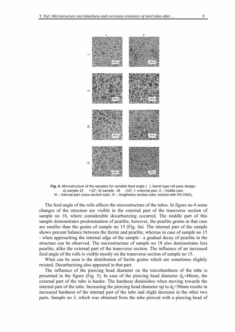
Fig. 4. Microstructure of the samples for variable feed angle (�), barrel type roll pass design:
a) sample 15 �=12°; b) sample 18 �=10°; I- external part, II – middle part, III – internal part cross-section tube, IV – lengthwise section tube; etched with 4% HNO3
The feed angle of the rolls affects the microstructure of the tubes. In figure no 4 some
changes of the structure are visible in the external part of the transverse section of sample no 18, where considerable decarburizing occurred. The middle part of this sample demonstrates predomination of pearlite, however, the pearlite grains in that case are smaller than the grains of sample no 15 (Fig. 4a). The internal part of the sample shows percent balance between the ferrite and pearlite, whereas in case of sample no 15 - when approaching the internal edge of the sample - a gradual decay of pearlite in the structure can be observed. The microstructure of sample no 18 also demonstrates less pearlite, alike the external part of the transverse section. The influence of an increased feed angle of the rolls is visible mostly on the transverse section of sample no 15.
What can be seen is the distribution of ferrite grains which are sometimes slightly twisted. Decarburizing also appeared in that part.
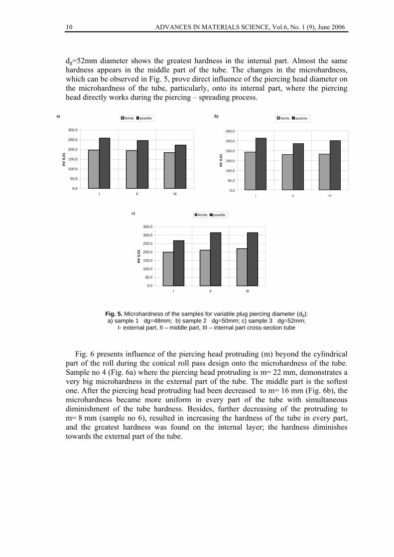
The influence of the piercing head diameter on the microhardness of the tube is presented in the figure (Fig. 5). In case of the piercing head diameter dg=48mm, the external part of the tube is harder. The hardness diminishes when moving towards the internal part of the tube. Increasing the piercing head diameter up to dg=50mm results in increased hardness of the internal part of the tube and slight decrease in the other two parts. Sample no 3, which was obtained from the tube pierced with a piercing head of
10 ADVANCES IN MATERIALS SCIENCE, Vol.6, No. 1 (9), June 2006
dg=52mm diameter shows the greatest hardness in the internal part. Almost the same hardness appears in the middle part of the tube. The changes in the microhardness, which can be observed in Fig. 5, prove direct influence of the piercing head diameter on the microhardness of the tube, particularly, onto its internal part, where the piercing head directly works during the piercing – spreading process.
0,0
50,0
100,0
150,0
200,0
250,0
300,0
I II III
HV
0,0
1
ferrite pearliteb)
0,0
50,0
100,0
150,0
200,0
250,0
300,0
I II III
HV
0,01
ferrite pearlitea)
0,0
50,0
100,0
150,0
200,0
250,0
300,0
350,0
I II III
HV
0,01
ferrite pearlitec)
Fig. 5. Microhardness of the samples for variable plug piercing diameter (dg): a) sample 1 dg=48mm; b) sample 2 dg=50mm; c) sample 3 dg=52mm;
I- external part, II – middle part, III – internal part cross-section tube
Fig. 6 presents influence of the piercing head protruding (m) beyond the cylindrical part of the roll during the conical roll pass design onto the microhardness of the tube. Sample no 4 (Fig. 6a) where the piercing head protruding is m= 22 mm, demonstrates a very big microhardness in the external part of the tube. The middle part is the softest one. After the piercing head protruding had been decreased to m= 16 mm (Fig. 6b), the microhardness became more uniform in every part of the tube with simultaneous diminishment of the tube hardness. Besides, further decreasing of the protruding to m= 8 mm (sample no 6), resulted in increasing the hardness of the tube in every part, and the greatest hardness was found on the internal layer; the hardness diminishes towards the external part of the tube.

T. Dyl: Microstructure microhardness and corrosion resistance of steel tubes after… 11
Fig. 6. Microhardness of the samples for variable advance plug piercing (m): a) sample 4 m = 22 mm; b) sample 5 m = 16mm; c) sample 6 m =8 mm;
I- external part, II – middle part, III – internal part cross-section tube
0,0
50,0
100,0
150,0
200,0
250,0
300,0
350,0
I II III
HV
0,01
ferrite pearliteb)
Fig. 7. Microhardness of the samples for variable advance plug piercing (m), barrel type roll pass design:
a) sample 16 m=16mm; b) sample 17 m=40mm; I- external part, II – middle part, III – internal part cross-section tube
0,0
50,0
100,0
150,0
200,0
250,0
300,0
350,0
I II III
HV
0,0
1ferrite pearlitea)
0,0
50,0
100,0
150,0
200,0
250,0
300,0
I II III
HV
0,01
ferrite pearliteb)
0,0
50,0
100,0
150,0
200,0
250,0
300,0
350,0
I II III
HV
0,0
1
ferrite pearlitec)
0,0
50,0
100,0
150,0
200,0
250,0
300,0
I II III
HV
0,0
1
ferrite pearlitea)
12 ADVANCES IN MATERIALS SCIENCE, Vol.6, No. 1 (9), June 2006
The influence of the piercing head protruding (m) beyond the cylindrical part of the roll during roll barrel pass design is presented in figure no 7. For sample no 16 (m = 16 mm), the external layer of the tube has got the greatest hardness. The hardness diminishes when moving towards the internal part. In case of sample no 17 (m = 40 mm), microhardness increases in every part; and the internal layer of the tube obtains the greatest hardness, while the external part – the least. So this is contrary to the situation of sample no 16. Thus it can be stated that increasing of the piercing head protruding (m) affects increasing of the hardness of the tube from the internal side during roll barrel pass design. Whereas, during the conical roll barrel pass design increasing of the piercing head protruding (m) affects adversely. Most probably this results from a different distribution of forces.
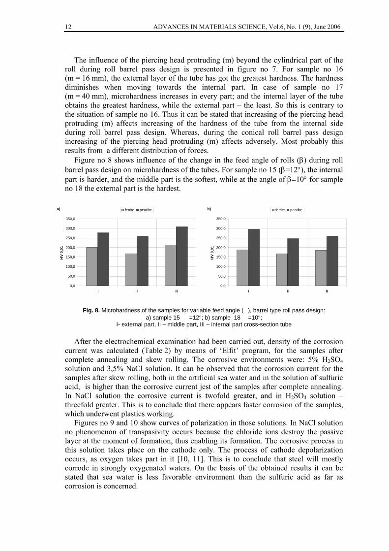
Figure no 8 shows influence of the change in the feed angle of rolls (β) during roll barrel pass design on microhardness of the tubes. For sample no 15 (β=12°), the internal part is harder, and the middle part is the softest, while at the angle of β=10° for sample no 18 the external part is the hardest.
0,0
50,0
100,0
150,0
200,0
250,0
300,0
350,0
I II III
HV
0,01
ferrite pearlitea)
0,0
50,0
100,0
150,0
200,0
250,0
300,0
350,0
I II III
HV
0,01
ferrite pearliteb)
Fig. 8. Microhardness of the samples for variable feed angle (�), barrel type roll pass design:
a) sample 15 �=12°; b) sample 18 �=10°; I- external part, II – middle part, III – internal part cross-section tube
After the electrochemical examination had been carried out, density of the corrosion
current was calculated (Table 2) by means of ‘Elfit’ program, for the samples after complete annealing and skew rolling. The corrosive environments were: 5% H2SO4 solution and 3,5% NaCl solution. It can be observed that the corrosion current for the samples after skew rolling, both in the artificial sea water and in the solution of sulfuric acid, is higher than the corrosive current jest of the samples after complete annealing. In NaCl solution the corrosive current is twofold greater, and in H2SO4 solution – threefold greater. This is to conclude that there appears faster corrosion of the samples, which underwent plastics working.
Figures no 9 and 10 show curves of polarization in those solutions. In NaCl solution no phenomenon of transpasivity occurs because the chloride ions destroy the passive layer at the moment of formation, thus enabling its formation. The corrosive process in this solution takes place on the cathode only. The process of cathode depolarization occurs, as oxygen takes part in it [10, 11]. This is to conclude that steel will mostly corrode in strongly oxygenated waters. On the basis of the obtained results it can be stated that sea water is less favorable environment than the sulfuric acid as far as corrosion is concerned.

T. Dyl: Microstructure microhardness and corrosion resistance of steel tubes after… 13
Table 2. The values the averages of corrosive parameters appointed with curves of polarization
Material Jc, mA/cm2
Jp, mA/cm2
Jkp, mA/cm2
Ec, mV
Ep, mV
Etp, mV
5% H2SO4
pipe subjected to skew rolling 0,95 0,05 339 -
450 - 150 1300
sample after full annealing 0,56 0,05 220 -
460 - 250 1300
3,5% NaCl pipe subjected to skew rolling 0,83 - - -
609 - -
sample after full annealing 0,37 - - -
620 - -
0.01 0.10 1.00 10.00 100.00 1000.00J, mA/cm^2
-700
-600
-500
-400
-300
U, m
V
2
1
Fig. 9. Potentiostatic polarization curves for 1 - full annealing sample and 2 - pipe subjected to skew rolling mill in range ± 150mV from potential corrosive in electrolytic solution of 5% H2SO4 [10]
In result of the microstructure observation by means of the optical microscope it can
be noted that skew rolling clearly affects the size, shape and distribution of ferrite and pearlite grains (sample no 15 and 16). The experiments prove that the piercing – spreading process of the tubes influences microhardness of particular structural components, as well. The value of microhardness of particular layers of the tube depend on selected parameters of the deflection area. In comparison to the insert material (non-alloy steel after complete annealing) the steel ferrite grains after the plastic working show distinct increase of microhardness, sometimes twofold. By contrast, microhardness of pearlite grains slightly increases, and sometimes the increase is very little. The geometrical parameters (diameter and the piercing head protruding, feed angle) for sample no 5 and no 16 were the same, the difference was affected by application of roll pass design. When using the conical roll pass design no orientation of grains was noticed. Whereas for roll barrel pass design directed deformation of the ferrite grains is visible. Therefore, it can be concluded that the conical roll pass design is

14 ADVANCES IN MATERIALS SCIENCE, Vol.6, No. 1 (9), June 2006
more favorable to form the structure of the tube in comparison to roll barrel pass design of the working rolls. Density of the corrosive current determines the corrosive resistance of the material. The electrochemical experiments show that the samples obtained by skew rolling are less resistant to corrosion, because the value of the corrosive current is much higher than in case of the samples after complete annealing.
0.00 0.01 0.10 1.00 10.00J, mA/cm^2
-750.00
-700.00
-650.00
-600.00
-550.00
-500.00
U, m
V
2
1
Fig. 10. Potentiostatic polarization curves for 1 - full annealing sample and 2 - pipe subjected to skew
rolling mill in range ± 150mV from potential corrosive in sea water [10, 11]
CONCLUSIONS
• The piercing – spreading process has substantial influence onto the microstructure and electrochemical resistance of the tubes.
• No essential influence of the geometrical parameters on the microhardness of particular layers of the tube was found.
• The most uniform distribution of ferrite and pearlite grains on the transverse and longitudinal sections were obtained for sample no 1, with the protruding value of m=32 mm and the piercing head diameter dg=48 mm for the conical roll pass design.
• Change in the piercing head diameter slightly affects the microstructure of the tube. • Protruding of the piercing head affects changes in the microstructure of the tube, for
conical roll pass design with smaller protruding (m=8 mm) there appear greater pearlite grains in the internal part of the tube, while for barrel roll pass design with smaller values of the piercing head protruding (m=16 mm) orientation of the ferrite grains may be observed.
• With bigger value of the feed angle (β=12°) decarburizing of the internal layer of the tube occurs.
• The samples which underwent the process of skew rolling have got greater microhardness of particular structural phases in comparison to the sample after complete annealing.

T. Dyl: Microstructure microhardness and corrosion resistance of steel tubes after… 15
• For the samples after the skew rolling density of the corrosive current is twofold or even threefold bigger than the value of corrosive current density for the samples after complete annealing. This means that the tubes will corrode faster both in sea waters and sulfuric acid.
REFERENCES
1. Hayashi Ch., Akiyama M., Yamakawa T.: Advancements in Cone-type Rotary Piercieng Technology, Journal of Manufacturing Science and Engineering, No. 8 (121) 1999, pp. 313-320
2. Matwiejew B.N.: Sowierszenstwowanije proizwodstwa trub iz wysokoljegirowan-nych staliej, Stal, No. 3 2000, pp. 56-59
3. Kazanecki J.: Wytwarzanie rur bez szwu, Uczelniane Wydawnictwa Naukowo-Dydaktyczne Akademii Górniczo Hutniczej, Kraków 2003
4. Dyl T., Dyja H., Garstka T.: Influences feed angle, diameter and advance plug piercing on expanding ratio, forcing and twisting parameters in piercing − spreading process, Metałłurgiczeskaja i Gornorudnaja Promyszljennost, No. 8-9 2002, pp. 350–355
5. Dyl T.: Wpływ kalibrowania walców na parametry geometryczne, skręcające i siłowe w procesie dziurowania − rozszerzania tulei w walcarce skośnej typu Dieschera, Hutnik-Wiadomości Hutnicze, Nr 5 (70) 2003, pp. 207 – 214
6. Dyl T.: Proces dziurowania – rozszerzania tulei w walcarce skośnej, Zeszyty Naukowe Akademii Morskiej w Gdyni, Nr 54, 2005, pp. 92-102
7. Dyl T., Starosta R.: Influence of geometrical parameters of the piercing – expanding process on pipe microstructure, Inżynieria Materiałowa Czasopismo Naukowo – Techniczne, Nr 3 (140) 2004, pp. 476–479
8. Skalski I.: Podstawy elektrochemii procesów korozyjnych. Dopasowanie krzywych teoretycznych do wyników badań polaryzacyjnych, Praca dyplomowa, Politechnika Gdańska, Wydział Chemiczny, 1999 (niepublikowana)
9. Jankowski J.: Wpływ ogniwa trójelektrodowego Sn – FeSn2 – Stal na korozję blachy białej, Rozprawa Doktorska, Politechnika Gdańska, Wydział Chemiczny, 1995 (niepublikowana)
10. Dyl T.: Wybrane własności warstwy wierzchniej tulei rurowych ze stali C45, Inżynieria Materiałowa Czasopismo Naukowo – Techniczne, Nr 5 (147) 2005, pp. 634-636
11. Starosta R., Dyl T., Formela M.: Wpływ procesu walcowania skośnego na odporność korozyjną tulei w wodzie morskiej, Materiały i Technologie, Roczniki Naukowe Pomorskiego Oddziału Polskiego Towarzystwa Materiałoznawczego, Nr 3 (3) 2005, pp. 241-244