Microstructural Property Co-relation of Diffusion Bonded High Strength Steel

Willie R. Prudente .et.al. Int. Journal of Engineering Research and Application www.ijera.com
ISSN : 2248-9622, Vol. 7, Issue 4, ( Part -4) April 2017, pp.67-71
www.ijera.com DOI: 10.9790/9622-0704046771 67 | P a g e
Microstructural evolution under tempering heat treatment in
AISI H13 hot-work tool steel
Prudente W. R.1, Jefferson Fabrício C. Lins
1, Siqueira R. P.
1, Priscila S. N.
Mendes1, Rodrigo E. Pereira
1
1 Department of Metallurgical Engineering, Fluminense Federal University, Volta Redonda, RJ, Brazil.
ABSTRACT The steel studied in this work belongs to the hot working class of tool steels in its applications it is essential that
the tool steel have high mechanical strength properties at high temperatures in order to avoid failure due to
thermal fatigue, plastic deformation, crack propagation and wear. In high temperature applications the most
desirable properties are the hot hardness (Red-Hardness), tempering resistance and fatigue resistance. To meet
these requirement alloying elements with strong carbide formation such as Cr, V and Mo are used. The softening
resistance of these tool steels is determined by changes suffered by the alloy carbides at high temperature and
due to the recovery of the martensitic structure. Thus, the final effects of heat treatment on the microstructure
and mechanical properties of the AISI H13 tool steel were studied. Microstructural characterization of samples
was performed with the aid of the x-ray diffraction and scanning electron microscopy techniques.
Keywords: AISI H13, Alloy Carbides, Heat Treatment, Secondary Hardening, Tool Steel.
I. INTRODUCTION Previous research on hot work tool steels
has shown that softening during tempering and
fatigue at high temperature is strongly linked to the
microstructure and its stability at high temperatures
[1]. Typical microstructures of tool steels for hot
work consist of annealed martensite with high
density of dislocations and alloy carbide. The
softening resistance of these tool steels is determined
by changes in the alloy carbides at an elevated
temperature and due to the recovery of the
martensitic structure.
The AISI H13 is a chromium hot-work tool
steel. Its chemistry is designed to withstand the
temperature, pressure, abrasion, and thermal cycling
associated with various hot working operations,
including plastic injection molding, die casting,
forging, and extrusion. The steel has low carbon
content, around 0.4 wt.%, to promote toughness.
Medium chromium content, around 5 wt.% to
provide good resistance to high temperature
softening, small percentage of Si to improve high
temperature oxidation resistance, and small
molybdenum and vanadium additions (about 1%)
that form stable carbides to increase resistance to
erosive wear [2].
The volumetric fraction, size, morphology
and distribution of the carbides have strong effects
on the mechanical properties of the steel. Studies
have shown that the effect of increased resistance
caused by the precipitation of carbides can
significantly increase the mechanical properties of
the steel [3], thus the final effects of the heat
treatment on the microstructure and mechanical
properties of AISI H13 steel have been extensively
studied.
II. EXPERIMENTAL PROCEDURE II.1 MATERIALS
The material used in the proposed work are
samples taken from an AISI H13 tool steel ingot,
supplied by Villares siderurgy, the samples have
dimensions of 10x10mm and 25mm length and their
chemical composition is shown in Table 1.
Table 1 - Chemical composition of H13 hot-work
tool steel used (wt.%).
%C %Si %Mn %Cr %Mo %V
0,40 0,50 0,20 5,20 1,30 0,80
II.2 METHODS
To study the influence of tempering
temperature 5 samples were austenitized at 1020°C
for 0,5h and then 4 were tempered by varying the
temperature parameter. The treatments are shown in
Table 2.
Table 2 - Tempering conditions for hardness
evolution measurements, carbides and martensite
laths analysis.
Tempering
Sample
Temperature Time
1 500ºC 2h
2 550ºC 2h
3 600ºC 2h
4 650ºC 2h
RESEARCH ARTICLE OPEN ACCESS

Willie R. Prudente .et.al. Int. Journal of Engineering Research and Application www.ijera.com
ISSN : 2248-9622, Vol. 7, Issue 4, ( Part -4) April 2017, pp.67-71
www.ijera.com DOI: 10.9790/9622-0704046771 68 | P a g e
II.2.1 METALLOGRAPHIC PREPARATION
The samples were grinded on the Arotec
Aropol 2V equipment, with a silica carbide
sandpaper sequence of 400 #, 600, 800 #, 1000 #,
1200 #, # 1500 and 2500 #. For the polishing of the
samples, 3 and 1μm granulation diamond paste were
used, and the final polishing was done with colloidal
silica OPS. Finally, the etch was done with 5% nital.
II.2.2 SCANNING ELECTRON MICROSCOPY
(SEM)
In this technique a beam of electrons of
controlled diameter is projected on the surface of the
sample to be analyzed acquiring signals caused by
collisions of these electrons with the electrons of the
surface of the sample.
The microstructures of the samples were
observed with the aid of a microscope Zeiss EVO
Scanner MA10 with LaB6 filament.
II.2.3 X-RAY DIFFRACTION (DRX)
This technique allows us to identify the
crystal structure, crystallographic texture and
orientation relationship between the phases. X-ray
diffraction (XRD) analysis was performed using a
Shimadzu Lab X XRD-600 diffractometer, using
Cu-Kα radiation, with a standard goniometer. A
voltage of 30 kV, current of 30 mA was applied
during a scan between 10º and 85° of 2θ, with the
step speed of 2θ equal to 0.02° and a scan speed of
2°/minute. The peaks were identified by comparing
the experimental data and the files from the Pearson
Crystal Data (PCD) using the Powder Cell program.
II.2.4 HARDNESS ROCKWELL C (HRC)
After microstructural analysis the samples
were submitted to fifteen Rockwell C hardness tests
with a load of 150kgf for 20s in a Süssen - Wolpert
durometer Testor HT model.
III. RESULTS AND DISCUSSION III.1 MICROSTRUCTURAL
CHARACTERIZATION
The microstructure evolution of the steel
was investigated by XRD, scanning electron
microscopy (SEM) and the quantitative image
analysis was carried out with the software IMAGEJ
and the ASTME1245 standard.
In the as-quenched condition, the parent
austenite phase transforms into martensite which is
accompanied by homogeneous elastic lattice
deformation and by a significant increase in
dislocation density [4].
Tempering promotes a diffusion type phase
transformation from a quenched martensite (B.C.T. -
body centered tetragonal) to a tempered martensitic
structure (B.C.C. – body centered cubic). The
carbides formation and growth is strongly related to
tempering time and temperature. Hence, establishing
a relation between tempering conditions and
microstructures is of great interest [5]. The
microstructure of the steel in the as quenched state is
shown in Fig. 1.
Figure 1 – AISI H13 tool steel SEM-SE micrograph
of the as-quenched microstructure.
In this state the steel has a martensitic
structure with high defect density, non-dissolved
carbides, usually vanadium rich carbides, during
austenitization (as can be observed in Fig. 3 to
dissolve all carbides a high temperature is needed)
and possibly some retained austenite [6].
In Fig. 2 it is possible to see the fine
vanadium carbides which did not dissolve during
austenitization.
Figure 2 - AISI H13 tool steel SEM-SE micrograph
of the as-quenched microstructure.
The curve shown in Fig. 3 was obtained
using the Thermo-Calc software version 4.0 with the
TCFe7 database. A legend with the phases found by
the software is presented in table 3.

Willie R. Prudente .et.al. Int. Journal of Engineering Research and Application www.ijera.com
ISSN : 2248-9622, Vol. 7, Issue 4, ( Part -4) April 2017, pp.67-71
www.ijera.com DOI: 10.9790/9622-0704046771 69 | P a g e
Table 3 - Legend of the Fig.3 graphic.
BCC_A2 – Ferrite α (CCC)
FCC_A1 – Austenite γ (CFC)
M23C6 – Cr rich carbide
M7C3 – Cr rich carbide
HCP_A3 – Mo rich carbide
FCC_A1#2 – V rich carbide
Figure 3 – It is shown the phase transformation
temperature as well as the alloy carbides dissolution
temperature of the AIS H13 tool steel.
In Fig. 4, 5, 6 and 7 is presented the tool
steel under different tempering conditions. It is
possible to note how the martensite laths increase in
size and thickness with increasing temperature.
Figure 4 - SEM-SE micrograph of the AISI H13
tool steel tempered at 500ºC for 2 hours SEM-SE
micrograph.
Figure 5 - SEM-SE micrograph of the AISI H13
tool steel tempered at 550ºC for 2 hours SEM-SE
micrograph.
Figure 6 - SEM-SE micrograph of the AISI H13
tool steel tempered at 600ºC for 2 hours.
Figure 7 - SEM-SE micrograph of the AISI H13
tool steel tempered at 650ºC for 2 hours SEM-SE
micrograph
Tempering is a very complex phenomenon
originating from the as-quenched microstructure of
tool steels, which consists primarily of martensite
with retained austenite and carbides. When hardened
steel is tempered, the tetragonality of the martensite
decreases and then disappears, which results in
Willie R. Prudente .et.al. Int. Journal of Engineering Research and Application www.ijera.com
ISSN : 2248-9622, Vol. 7, Issue 4, ( Part -4) April 2017, pp.67-71
www.ijera.com DOI: 10.9790/9622-0704046771 70 | P a g e
decrease in internal stresses. Dislocations anneal-out
at 400 °C. Therefore, there is decrease in the
dislocation density [4]. When steel is tempered at
600°C, the following changes in the matrix take
place: internal stresses decrease; dislocations anneal-
out; and coalescence of carbides [7].
The secondary hardening is a strengthening
resulting of the replacement of coarse particles of
Fe3C, which dissolve, by a fine dispersion of alloy
carbides such as VC, Cr7C3, Cr23C6, Mo2C or
Mo6C. Chromium additions result in a retardation in
softening but little secondary hardening because
Cr7C3 coarsens very rapidly at tempering
temperatures [8]. These alloy carbides are
responsible for the hardness and wear resistance in
this steel
It was noticed that with the increase of the
tempering temperature, more carbides were present
in the microstructure, thus, 10 images at the
magnification of 5000 were made and analyzed
following the ASTME1245 standard, the volumetric
fraction of carbides was then calculated. The mean
value is presented in table 4.
Tabela 4 - Mean value of volume fraction obtained
by image analysis for the 2 hours tempered samples.
Mean(%) S 95% CI %RA
500ºC 1,4053 0,3049 0,2181 15,5216
550ºC 1,6105 0,2697 0,1929 11,9805
600ºC 2,0579 0,3003 0,2148 10,4365
650ºC 3,7053 0,4433 0,3171 8,5575
In accordance with the ASTM standard it is
shown in the table 4 the mean value of the volume
fraction ( ), the standard deviation (S), it is also
reported the 95% confidence interval for each set of
fields and the relative accuracy (%RA). It can be
seen that the volume fraction highly increases with
the temperature.
To analyze the martensite laths 10 images
at 2000 magnification were made and analyzed
through threshold and labeling, a histogram was
made to understand the growth tendency of the
martensite laths as shown in Fig. 8.
Figure 8 - Distribution of martensitic lath width
It can be seen that in all cases the majority of
laths have 1μm width and as the temperature
increases the width increases.
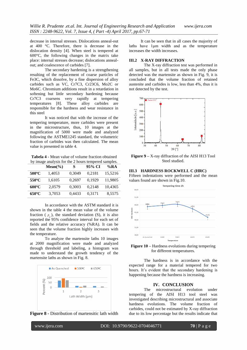
III.2 X-RAY DIFFRACTION
The X-ray diffraction test was performed in
all samples, but in all tests made the only phase
detected was the martensite as shown in Fig. 9, it is
concluded that the volume fraction of retained
austenite and carbides is low, less than 4%, thus it is
not detected by the test.
Figure 9 – X-ray diffraction of the AISI H13 Tool
Steel studied.
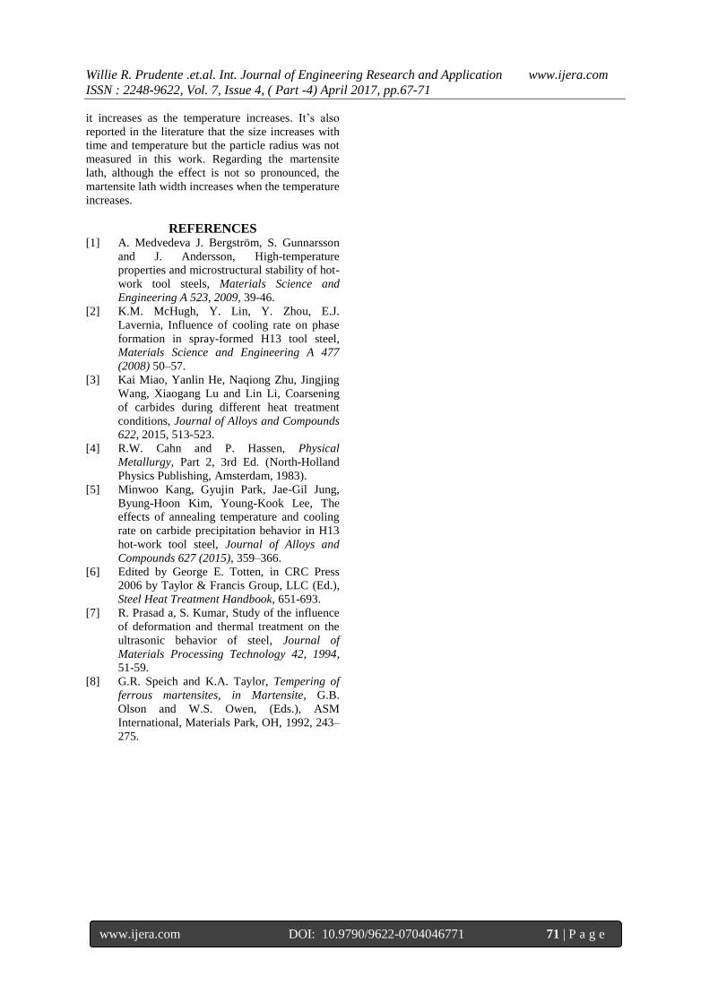
III.3 HARDNESS ROCKWELL C (HRC) Fifteen indentations were performed and the mean
values found are shown in Fig.10.
Figure 10 – Hardness evolutions during tempering
for different temperatures.
The hardness is in accordance with the
expected range for a material tempered for two
hours. It’s evident that the secondary hardening is
happening because the hardness is increasing.
IV. CONCLUSION The microstructural evolution under
tempering of the AISI H13 tool steel was
investigated describing microstructural and associate
hardness evolutions. The volume fraction of
carbides, could not be estimated by X-ray diffraction
due to its low percentage but the results indicate that
Willie R. Prudente .et.al. Int. Journal of Engineering Research and Application www.ijera.com
ISSN : 2248-9622, Vol. 7, Issue 4, ( Part -4) April 2017, pp.67-71
www.ijera.com DOI: 10.9790/9622-0704046771 71 | P a g e
it increases as the temperature increases. It’s also
reported in the literature that the size increases with
time and temperature but the particle radius was not
measured in this work. Regarding the martensite
lath, although the effect is not so pronounced, the
martensite lath width increases when the temperature
increases.
REFERENCES [1] A. Medvedeva J. Bergström, S. Gunnarsson
and J. Andersson, High-temperature
properties and microstructural stability of hot-
work tool steels, Materials Science and
Engineering A 523, 2009, 39-46.
[2] K.M. McHugh, Y. Lin, Y. Zhou, E.J.
Lavernia, Influence of cooling rate on phase
formation in spray-formed H13 tool steel,
Materials Science and Engineering A 477
(2008) 50–57.
[3] Kai Miao, Yanlin He, Naqiong Zhu, Jingjing
Wang, Xiaogang Lu and Lin Li, Coarsening
of carbides during different heat treatment
conditions, Journal of Alloys and Compounds
622, 2015, 513-523.
[4] R.W. Cahn and P. Hassen, Physical
Metallurgy, Part 2, 3rd Ed. (North-Holland
Physics Publishing, Amsterdam, 1983).
[5] Minwoo Kang, Gyujin Park, Jae-Gil Jung,
Byung-Hoon Kim, Young-Kook Lee, The
effects of annealing temperature and cooling
rate on carbide precipitation behavior in H13
hot-work tool steel, Journal of Alloys and
Compounds 627 (2015), 359–366.
[6] Edited by George E. Totten, in CRC Press
2006 by Taylor & Francis Group, LLC (Ed.),
Steel Heat Treatment Handbook, 651-693.
[7] R. Prasad a, S. Kumar, Study of the influence
of deformation and thermal treatment on the
ultrasonic behavior of steel, Journal of
Materials Processing Technology 42, 1994,
51-59.
[8] G.R. Speich and K.A. Taylor, Tempering of
ferrous martensites, in Martensite, G.B.
Olson and W.S. Owen, (Eds.), ASM
International, Materials Park, OH, 1992, 243–
275.