Micromorphology of diamicton affected by iceberg- keel ...
53
Micromorphology of diamicton affected by iceberg- keel scouring, Scoresby Sund, East Greenland Lorna D. Linch a, *, Julian A. Dowdeswell b a School of Environment and Technology, University of Brighton, Lewes Road, BN2 4GJ, United Kingdom b Scott Polar Research Institute, University of Cambridge, Lensfield Road, Cambridge, CB2 1ER, United Kingdom * Corresponding author E -mail address: [email protected] (L.D. Linch). Keywords: Iceberg scours, Ploughmarks, G ouges, M icrom orphology, D iam icton, Ic -rafted debris (IRD), Scoresby Sund, East Greenland ABSTRACT Icebergs are important as agents of deposition and seafloor reworking on glacier-influenced continental margins. When the keel of an iceberg exceeds water depth it ploughs through soft sediments producing scours/ploughmarks that can be kilometres long, hundreds of metres wide and sometimes tens of metres deep. Because the influence of iceberg keels on sediment is a critical factor when offshore structures (e.g. pipelines, power cables) are installed, the surface morphology of iceberg scours on the seafloor is relatively well- documented. Less however, is known about sub-scour deformation below the seafloor. This is particularly true of iceberg scoured diamicton (poorly sorted sediment comprising a variety of particle sizes), which is present in many high-latitude fjords and continental shelves. The aim of this research is to examine directly (macroscopically and microscopically, with thin sections) the style and intensity of deformation caused by the scouring action of iceberg keels in diamicton offshore of East Greenland. Results show that a distinctive suite of deformation structures (individual structures and overprinted structural patterns) dominated by planar shear, sediment mixing and high porewater, and dropstones characterises iceberg scoured diamicton. In addition, diamicton from areas of high-intensity iceberg scouring tends to show a wider variety, higher frequency and distribution, more abundant and better-developed deformation structures than diamicton from areas of intermediate- and low-intensity iceberg scouring. Characterising the effects of iceberg scour in diamicton is important more widely to inform: i) reconstruction of the geometry and dynamics of former ice sheets; and ii) installation and protection of offshore engineering structures in diamicton where iceberg scouring presents a geohazard. The value of micromorphology is significant especially in the absence of macroscopic sediment exposures/outcrops where the study of cores is necessary instead. 1. Introduction When the keels of icebergs and ice-pressure ridges come into contact with unconsolidated sea or lake bed sediment, and winds, currents and the energy released during calving events propel the ice masses forward, the ice keels will cut into the bed to form scour marks (also known as ‘ploughmarks’ (Dowdeswell and Ottesen, 2013) and ‘gouges’ (Palmer and Chan, 2012)). In this paper the term ‘ice keel scour’ is used to describe scour by either icebergs or
Transcript of Micromorphology of diamicton affected by iceberg- keel ...
Micromorphology of diamicton affected by iceberg-keel scouring, Scoresby Sund, East Greenland
Lorna D. Linch a, *, Julian A. Dowdeswell b
a School of Environment and Technology, University of Brighton, Lewes Road, BN2 4GJ, United Kingdom
b Scott Polar Research Institute, University of Cambridge, Lensfield Road, Cambridge, CB2 1ER, United Kingdom
* Corresponding author E-mail address: [email protected] (L.D. Linch).
Keywords: Iceberg scours, Ploughmarks, Gouges, M icrom orphology, D iam icton, Ic-rafted debris (IRD), Scoresby Sund, East Greenland
ABSTRACT
Icebergs are important as agents of deposition and seafloor reworking on glacier-influenced continental margins. When the keel of an iceberg exceeds water depth it ploughs through soft sediments producing scours/ploughmarks that can be kilometres long, hundreds of metres wide and sometimes tens of metres deep. Because the influence of iceberg keels on sediment is a critical factor when offshore structures (e.g. pipelines, power cables) are installed, the surface morphology of iceberg scours on the seafloor is relatively well-documented. Less however, is known about sub-scour deformation below the seafloor. This is particularly true of iceberg scoured diamicton (poorly sorted sediment comprising a variety of particle sizes), which is present in many high-latitude fjords and continental shelves. The aim of this research is to examine directly (macroscopically and microscopically, with thin sections) the style and intensity of deformation caused by the scouring action of iceberg keels in diamicton offshore of East Greenland. Results show that a distinctive suite of deformation structures (individual structures and overprinted structural patterns) dominated by planar shear, sediment mixing and high porewater, and dropstones characterises iceberg scoured diamicton. In addition, diamicton from areas of high-intensity iceberg scouring tends to show a wider variety, higher frequency and distribution, more abundant and better-developed deformation structures than diamicton from areas of intermediate- and low-intensity iceberg scouring. Characterising the effects of iceberg scour in diamicton is important more widely to inform: i) reconstruction of the geometry and dynamics of former ice sheets; and ii) installation and protection of offshore engineering structures in diamicton where iceberg scouring presents a geohazard. The value of micromorphology is significant especially in the absence of macroscopic sediment exposures/outcrops where the study of cores is necessary instead.
1. Introduction
When the keels of icebergs and ice-pressure ridges come into contact with unconsolidated sea or lake bed sediment, and winds, currents and the energy released during calving events propel the ice masses forward, the ice keels will cut into the bed to form scour marks (also known as ‘ploughmarks’ (Dowdeswell and Ottesen, 2013) and ‘gouges’ (Palmer and Chan, 2012)). In this paper the term ‘ice keel scour’ is used to describe scour by either icebergs or
ice-pressure ridges (Linch and van der Meer, 2014). As well as deforming and excavating the sediment within the scour, the ice keel deforms the sediment a significant distance (up to several metres) below the base of the scour trough, known as ‘sub-scour deformation’ (e.g. Woodworth-Lynas and Guigné, 1990; Linch et al., 2012; Palmer and Chan, 2012; Linch and van der Meer, 2014).
Several studies have investigated sub-scour deformation both onshore (e.g. Woodworth-Lynas and Landva, 1988; Longva and Bakkejord, 1990; Woodworth-Lynas and Guigné, 1990; Woodworth-Lynas, 1992; Rocha-Campos et al., 1994; Eyles et al., 1997, 2005; Eden and Eyles, 2001; Eyles and Meulendyk, 2008; Linch et al., 2012; Linch and van der Meer, 2014) and offshore (Kilfeather et al., 2010). This previous work has shown that a distinctive suite of structures (dominated by planar shear, sediment mixing and porewater structures) characterises i) iceberg scoured clays and ii) ice keel scoured pebbly sandy mud and fine-grained sands, which is unlike those structures associated with subglacial tills and mass-wasting deposits (Linch et al., 2012; Linch and van der Meer, 2014). However, ice keel scoured diamicton (poorly sorted sediment comprising a variety of particle sizes) is reported from Late Quaternary sediments in a number of high-latitude fjords and continental shelves, including much of the 500,000 km2 shelf around the coast of Greenland (Dowdeswell et al., 1993, 1994a,b) and around Antarctica (Anderson, 1999), yet the structures it contains are poorly known.
It follows that iceberg rafted and scoured diamicton must also be found in at least a proportion of the ancient sequences of Late Cenozoic and pre-Late Cenozoic glacier-influenced sediments (Dowdeswell et al., 1994a). However, macroscopically massive diamicton facies associated with Late Cenozoic and earlier glaciations are interpreted relatively rarely as resulting from iceberg- related processes, and when found in glacimarine settings are more often ascribed to ice-shelf basal processes (Dowdeswell et al., 1994a). In some cases iceberg rafted and scoured diamicton may even have been misidentified as subglacial in origin (Dowdeswell et al., 1994a) and/or deposited by mass-wasting. This is probably because, until now, there has been little means of identifying iceberg scoured diamicton and distinguishing it from other types of diamicton.
Since fast-flowing outlet glaciers and ice streams are the principal source of icebergs and ice-rafted debris (IRD) entering the marine environment (Ó Cofaigh et al., 2001), being able to recognise iceberg rafted and scoured diamicton in the modern and ancient glacimarine sedimentary record could be indicative of the presence of fast-flowing outlet glaciers and/or ice streams draining large ice masses, which is crucial for reconstructing the geometry and dynamics of former ice sheets (Dowdeswell et al., 1994a; Ó Cofaigh et al., 2001). In turn, it may lead to the reinterpretation of diamicton currently considered to be, for example, subglacial (Dowdeswell et al., 1994a; Eden and Eyles, 2001), which will hold implications for existing ice sheet and glacier reconstruction models. In addition, understanding scouring processes, particularly the style and intensity of sub-scour deformation, is a critical first step to inform the safe installation and protection of offshore structures (e.g. pipelines) in diamicton where iceberg scouring presents a geohazard (e.g. Woodworth-Lynas et al., 1996; Barker and Timco, 2002, 2003; Been et al., 2008; Sancio et al., 2011; Palmer and Chan, 2012).
The question addressed in this paper is, therefore - does a distinctive suite of structures characterise iceberg scoured diamicton? To answer this, the aim of this investigation is to macroscopically and microscopically examine iceberg scoured diamicton from Scoresby
Sund, East Greenland.
2. Study area
2.1. Relief and geology
The Scoresby Sund fjord system (70-72°N) is noted for some of the world's longest and deepest fjords (Funder, 1972). It covers an area of 13,700 km2 with a distance of 350 km between the head of the inner fjords and the fjord mouth (Fig. 1) (Dowdeswell et al., 1993, 1994a,b). The inner fjords (including Gassefjord, Fønfjord, Øfjord and Nordvestfjord) of the system are deep (800-1600 m) and narrow (<6 km wide) with steep slopes (Dowdeswell et al., 1993, 1994a,b; 2016; Ó Cofaigh et al., 2001). This irregular topography facilitates development of localised gravity flows and acoustically laminated basin fill in the inner fjords (Ó Cofaigh et al., 2001). In contrast, the wide and relatively flat-floored outer fjord (Hall Bredning to the north, and Scorseby Sund sensu stricto to the south) is up to 50 km wide, with water depths of 200-650 m (Dowdeswell et al., 1993, 1994a,b; Ó Cofaigh et al., 2001). In this paper, the term ‘Scoresby Sund’ is used to describe the broad part of the outer fjord. Whereas high mountain plateaux dominate the innermost part of the fjord system, the northern part of the region and the area near the coast in Liverpool Land are characterised by mountain areas with alpine relief, and Jameson Land and parts of southern Milne Land are typified by extensive areas of hilly lowland (Funder, 1972). Archean to Caledonian magmatic and metamorphic rocks form Gåseland, Milne Land and Renland in the west and Liverpool Land in the east (Marienfield, 1992a). The Geike Plateau south of Scoresby Sund consists of Tertiary plateau basalts while Jameson Land is composed of mostly Mesozoic sedimentary rocks, which are covered by glacial sediments (Marienfield, 1992a).
2.2. Icebergs
Today, glacier and ice-sheet fed ice cliffs occupy 85 km of the fjord coastline of the Scoresby Sund system (Dowdeswell et al., 1992). Fast-flowing outlet glaciers entering the fjords are among the largest producers of icebergs on the eastern margin of the Greenland Ice Sheet (Koch, 1945; Reeh, 1985); accounting for approximately 18 km3 of mass loss into the fjord system annually (Olsen and Reeh, 1969). Two of these outlet glaciers, Daugaard- Jensen Gletscher and Vestfjord Gletscher (Fig. 1), contribute approximately 75% of calved icebergs into the fjord system each year (Reeh, 1985; Dowdeswell et al., 1994a,b; Ó Cofaigh et al., 2001). More recent estimates from the period 2000-2010 measured an ice flux at the grounding-line of Daugaard-Jensen Gletscher of 25 km3 yr-1, although a daily submarine melt rate of about 2.5 m per day means that calving may account for only 4 km3 yr-1 (Enderlin and Howat, 2013). These two outlet glaciers produce tabular icebergs between 100 m and 2.5 km in width, and up to 600 m in thickness (Dowdeswell et al., 1992); by contrast smaller tidewater glaciers tend to produce smaller icebergs of irregular shape (Dowdeswell et al., 1994a,b). The net drift of icebergs is to- wards the mouth of the fjord system where icebergs leave the outer fjord on its southern side (Dowdeswell et al., 1993).
2.3. Iceberg rafted diamicton
Only ~5-15 m of unlithified Quaternary sediments, which directly overlie Upper Palaeozoic to Mesozoic sedimentary bedrock, are present in Scoresby Sund (Dowdeswell et al., 1991). It is thought that during the Last Glacial Maximum (LGM), a glacier filled the fjords and extended onto the East Greenland shelf (Håkansson et al., 2007), eroding most or all
Quaternary sediments from the outer fjord, indicating that the current thin sedimentary record comprises almost exclusively the postglacial period (Marienfield, 1991a,b, 1992a; Dowdeswell et al., 1994b; Ó Cofaigh et al., 2001). Ice retreat up the inner fjord is recorded by radiocarbon dates indicating that ice reached approximately its present extent by 6-7 ka BP (Funder, 1978; Marienfield, 1991b; Dowdeswell et al., 1994a,b). Therefore, glacier ice has been absent from the outer fjord throughout the Holocene (Dowdeswell et al., 1994a,b; Funder et al., 2011).
Unlithified sedimentary facies and modern sedimentary processes in Scoresby Sund are discussed in detail in several publica- tions (e.g. Marienfield, 1991a,b, 1992a,b; Stein et al., 1993; Dowdeswell et al., 1992, 1993, 1994a,b; Ó Cofaigh et al., 2001). In summary, cores retrieved from Scoresby Sund comprise: i) ~90% macroscopically massive diamicton (Dm), formed by the release of IRD and reworking by iceberg scouring; ii) ~4% lenses or beds of gravel or coarse sand with sharp contacts (within diamicton), indicating iceberg dumping of debris; iii) ~4% laminated sediments (Fl) of alternating fine sand to coarse silt and fine silt to clay with some large clasts (gravels to cobbles); and iv) ~3% crudely layered, less well-sorted sediments (Fsd) with a significant proportion of larger clasts (Dowdeswell et al., 1994a,b). The two layered/laminated facies (Fl and Fsd) are restricted mainly to the lower parts of cores that were retrieved from deeper waters on the southern side of Scoresby Sund, and are thought to indicate sedimentation from meltwater at times when sediment delivery by icebergs was suppressed by a semi-permanent cover of sea ice in the fjord system (Dowdeswell et al., 1994a,b). Marine reservoir corrected accelerator mass spectrometer (AMS) radiocarbon dates show that the upper contact of the laminated facies (Fl) with the overlying macroscopically massive diamicton (Dm) occurs at dates of about 10 ka BP (Marienfield, 1991b). The Holocene section is therefore made up almost entirely of macroscopically massive diamicton facies, with scattered clast-rich beds/lenses embedded within it (Dowdeswell et al., 1994a,b). Below the laminated facies, undated diamicton (similar to the diamicton deposited during the Holocene) is also thought to originate from iceberg rafting and scouring, although this is still open to debate (Dowdeswell et al., 1994b). Note that the current investigation is only concerned with examining the macroscopically massive diamicton.
Diamictic sediment can be produced in a variety of depositional environments by a range of processes including direct formation as subglacial till, debris-flow processes, rainout from ice shelves or floating glacier tongues, and iceberg rafting and scouring (e.g. Dowdeswell et al., 1994a; Laberg and Vorren, 2000; Evans et al., 2006; Kilfeather et al., 2010). Although there are several possible local sources of sediment to Scoresby Sund including subglacial streams draining tidewater glaciers, subaerial rivers fed by glaciers and snowmelt, local rockfalls and aeolian transport; iceberg rafting is thought to be of considerable regional importance due to the very large numbers of icebergs traversing the outer fjord of the Scoresby Sund system (Dowdeswell et al., 1994a,b). The common presence of coarse particles (>2 mm) in cores from the outer fjord demonstrates that the release of debris from icebergs is indeed a significant process (Grobe, 1987; Stein et al., 1993; Dowdeswell et al., 1994a,b). The debris included within icebergs is assumed to originate from sequences of debris-rich ice formed at the base of outlet glaciers that calve icebergs into the fjord system (Dowdeswell et al., 1994a,b). Such basal debris-rich ice layers (a few centimetres to a few metres in thickness) have been reported from icebergs (exposed after overturn) in Antarctica (Anderson et al., 1980), Svalbard (Dowdeswell and Dowdeswell, 1989) and Scoresby Sund (Dowdeswell et al., 1994b). Subsequently, as icebergs drift through the fjord system they undergo melting, which releases debris included within the ice (Dowdeswell et

al., 1994a,b). Isolated lenses of gravel or coarse sand (rarely exceeding 10 cm in thickness) within the diamicton in cores from the outer fjord probably indicate iceberg overturn and the quasi-instantaneous dumping of any sediment accumulated on the iceberg surface (Vorren et al., 1983; Marienfield, 1992a; Dowdeswell et al., 1994a,b). Sea-ice rafting is less important here because water depths within the outer fjord are in hundreds of metres rather than tens of metres, so freezing-on of debris when ice floes contact the bed is severely restricted (Dowdeswell et al., 1994a,b). Diamicton in this investigation, therefore, is already well-established as a product of iceberg rafting and scouring in a glacimarine environment (Dowdeswell et al., 1993, 1994a,b; Ó Cofaigh et al., 2001). Certainly, radiocarbon dates show that glacial ice was absent from the outer fjord throughout the Holocene when this diamicton was deposited (Dowdeswell et al., 1994a,b). Moreover, the outer fjord is wide and relatively flat (Ó Cofaigh et al., 2001) with little evidence (on acoustic records) of sub-aqueous mass-wasting, and turbid melt- water plumes are restricted to within a few kilometres of fjord shores (Dowdeswell et al., 1994b). Therefore, diamicton is unrelated entirely to subglacial processes and is highly unlikely to be related to, or affected by, processes of mass-wasting (including turbidity currents and debris flows).
2.4. Seafloor scouring by iceberg keels
During September 1990 radar and sextant observations made along two transects across Hall Bredning and Scoresby Sund by F. S Polarstern showed that a number of icebergs in the outer fjord were grounded in water depths of <300 m on the shallower northeastern side of the outer fjord and up to 520 m on the south side (Dowdeswell et al., 1992, 1993). Parasound and 3.5 kHz acoustic measurements recorded seabed irregularities up to 10 m in height (from berm crest to the base of the trough) and widths of a few metres to 20 m or more (Dowdeswell et al., 1993). These irregularities are inferred to be scours because i) they are similar in morphology to those seen on 3.5 kHz records from the Labrador Shelf and Barents Sea (Josenhans et al., 1986; Solheim et al., 1988); ii) Dowdeswell et al. (1992, 1993) observed a large number of ice- bergs with keels deeper than the measured water depths; and iii) the dimensions of these seabed irregularities are consistent with previous scour descriptions in terms of size and berm/trough morphology. Given sedimentation rates in Scoresby Sund over the last 10 ka are on the order of 0.2-0.3 mm yr-1 (Marienfield, 1992a), it is likely that, as well as modern scours, relict scours dating back to the Late Wiechselian are probably also present on the modern sea floor, and even older scours (Mid and Early Weichselian) are likely to exist throughout the sedimentary sequence where it has not been eroded by later glaciations (Dowdeswell et al., 1993).
Dowdeswell et al. (1993) define three classes of scour intensity in Scoresby Sund, which occur in water of progressively changing depth (Fig. 1B; Table 1). Parasound and 3.5 kHz measurements over 8000 km2 of the outer fjord indicate that 80% of the seafloor in this area is made up of unlithified sediments, which are scoured by iceberg keels; 5% is sedimentary material that is unaffected by scours; and the remaining 15% is composed of rock outcrop (Dowdeswell et al., 1993). Grounding and scouring by sea-ice keels (ice-pressure ridges) is of very little significance because maximum depths of sea-ice keels in this area have been measured (submarine sonar) at an average of 2.4 m with a maximum of 20 m (Dowdeswell et al., 1993).
3. Methods
Geophysical data were obtained from Scoresby Sund during two cruises aboard F. S.
Polarstern. A limited set of acoustic profiles from a 3.5 kHz sub-bottom echo sounder and a series of gravity cores (11.5 cm diameters) were acquired on the first cruise (ARKV/3b) in August 1988. More detailed acoustic profiles (Krupp Atlas Para- sound and Hydrosweep systems) and measurements of iceberg dimensions were acquired during the second cruise (ARKVII/3b) in September 1990. For the purpose of the current investigation, seven of these gravity cores were carefully chosen from i) high-intensity iceberg scoured (HIS) zones (PS1716-1, PS1716-2, PS1720-1, PS1721-1); ii) intermediate-intensity iceberg scoured (IIS) zones (PS1727-1); and iii) low-intensity iceberg scoured (LIS) zones (PS1718-1, PS1719-1) as outlined in Dowdeswell et al. (1993) (Fig. 1B and Table 1). The selected cores were all retrieved from within the boundaries of iceberg scoured zones (rather than from individual iceberg scours) as recognised at the seabed on Parasound records (Table 1). They were described macroscopically by eye and with the use of x-radiographs (Fig. 2) and 17 undisturbed samples were collected from diamicton facies for micromorphological analyses (Table 2). Micromorphological samples were selected on the basis of the macroscopic sediment texture and structure (Linch et al., 2012). In this investigation, this included for example, where laminae/beds, lenses, intraclasts, sediment domains etc. were identified and also representative areas where diamicton appeared macroscopically massive. Although there was no evidence of core disturbance (e.g. dragging of material) incurred from the gravity coring process, samples were selected away from the edges of the cores to avoid any potential disturbance.
Samples were acetone-dried and resin-impregnated; thin sections were produced following the procedures described in Lee and Kemp (1993), Carr and Lee (1998), and Menzies (2000). All thin sections were examined using a Leica© Z6 APO petrological microscope with a rotating stage (5.7x – 36x magnification). Descriptions follow classifications developed by Brewer (1976), van der Meer (1993), Menzies (2000), Linch et al. (2012) and Linch and van der Meer (2014). For grain roundness (Powers, 1953) and clast microfabric (i.e. grain orientation of elongate grains in relation to the top of the thin section: Carr and Rose, 2003) a sampling grid (where each grid square measures 1 cm2) was placed on top of a live computer image of each thin section at 8x magnification. Each 1 cm2 grid square on the computer screen equated to 580 µm2 grid square on the thin section image. Grain roundness and clast microfabric were then recorded at each grid square intersection, and assigned to three grain size categories: <500 µm, >500 µm and >2000 µm. The whole of each thin section was examined in this way (~50-100 grains were counted in each thin section depending on grain density).
Samples considered texturally representative of diamicton in each core (i.e. away from sand/gravel layers etc.) were collected in sealed, airtight sample bags for grain size analysis, carbonate con- tent and clay mineralogy, which are important factors in the context of the microscopic examination of sediment because they can affect the detectability, style and intensity of sediment deformation (van der Meer et al., 2003; Linch et al., 2012; Linch and van der Meer, 2014). For grain size analysis a Malvern Hydro Master- sizer 2000G was used; for carbonate content an Eijkelkamp Calcimeter (NEN-ISO 10693) was used; and for clay mineralogy PAnalytical x-ray diffraction equipment and the ethylene glycol method (Moore and Reynolds, 1997) were used.
4. Descriptions
The following provides macro- and micromorphological descriptions of diamicton from all seven cores exclusively as part of the current project. Previous macromorphological
descriptions can be found in e.g. Marienfield (1992a,b) and Dowdeswell et al. (1994a,b). Sedimentary facies for all cores are shown in Fig. 3 and a representative selection of full annotated thin section scans is shown in Fig. 4. It should be noted that, unless otherwise stated, all textural/structural measurements from this point forward reflect ‘apparent’ a-axes values as a consequence of the plane of slicing of the sample block during cutting. All angles are measured where the top of the thin section is 0°. A summary of micromorphological structures is illustrated in Table 3.
4.1. Macroscopic
All seven cores are characterised by fine-grained, matrix-sup- ported diamicton (2.5 Y 3/1 to 2.5 Y 5/4) comprising ~13-23% clay with variable silt (35-76%) and sand (3-48%) contents (Table 4). Diamicton may grade from being sandy to finer-grained, or vice versa (as indicated by dashed lines in Fig. 3). Vertically or horizontally aligned, sub-angular to sub-rounded pebbles (up to ~6 cm) are common. However, the distribution of pebbles can be variable (expressed by the size of the triangles in Fig. 3). Diamicton is macroscopically massive except where the occasional horizontal laminae/beds (up to 2.5 cm in thickness) are noted (e.g. clayey laminae; iron-rich silty laminae and beds; and sandy beds). Of these, clayey laminae in PS1718-1 are noticeably deformed (Fig. 3). In addition, gravel beds/lenses and coarse sand lenses are common. Gravel beds are aligned mostly horizontally, range between 0.5 and 7 cm in thickness and extend across the entire width of cores (11.5 cm). Sand lenses range from between 1 and 3.5 cm in thick- ness and 2.5-8.5 cm in length and are aligned horizontally. Vertically or horizontally oriented, rounded soft-sediment intraclasts (0.1-2 cm) comprising clayey, silty, sandy and calcareous material are common. Sediment domains of sandier diamicton are identified adjacent to domains of more clayey diamicton. In PS1718-1 and PS1719-1 the diamicton-dominated sequence also contains a 20-110 cm sequence of fine-grained laminated sediments (Fig. 3). Diamicton underlying laminated sediments is similar, if not the same, in composition to diamicton that overlies laminated sediments. At <4%, carbonate content is very low and unlikely to mask birefringent plasmic fabric (Table 4). Finally, although some smectite is present (~5-6°: after Velde, 1992), the fact that diamicton has only ever existed in a glacimarine environment (without sub-aerial exposure), and cores are well-wrapped and are stored permanently in a cold room, it is unlikely that deformation structures in thin section will be related to processes of shrink/swell (Brady and Weil, 1999).
4.2. Micromorphology
Microscopically, diamicton is fine-grained and matrix- supported with clasts (also known as ‘skeleton grains’, which are particles >30-35 µm in size - van der Meer and Menzies, 2011) ranging from <100 µm to up to 1.7 cm. Clasts <500 µm and >500 µm range from very angular to well-rounded, but they are dominantly sub-rounded with this being the modal roundness class in each core (Fig. 5). Clasts >2000 µm are largely angular, sub- angular or sub-rounded (Fig. 5). Clasts >2000 µm, >500 µm and <500 µm are preferentially horizontally oriented (Fig. 6). However, a sub-horizontal secondary (and sometimes third and fourth) preferred orientation(s) is often also identified (Fig. 6). Clasts are i) distributed evenly throughout; ii) concentrated in patches (e.g. domains, bands/layers, concentric/swirled arrangements); and/or iii) clustered in small groups of 3-10 clasts or more (‘grain dumps’). Diamicton petrography is dominated by quartz and feldspar but also reveals basaltic material and crystalline fragments with little systematic change in time (i.e. core depth) or space (i.e. between cores). Matrix (also known as ‘plasma’, which comprises

particles <30 µm in size - van der Meer and Menzies, 2011) is typically dense and fine-grained (or slightly more ‘grainy’ in sandy diamict), and is i) distributed evenly throughout, and/or ii) arranged in do- mains, bands and lineations (‘streaks’ up to ~20 mm in length and ~1 mm in thickness). Sometimes ‘zones’ of diamicton, characterised by distinct textures (in terms of clast vs. matrix ratios), are identified. Up to four texturally distinct ‘zones’ can occur side-by-side in the same thin section (Fig. 7A and B). Contacts between such ‘zones’ are typically diffuse and may be highly disturbed/mixed. Discontinuous, crudely stratified sandy and fine-grained beds (sometimes alternating), <3 mm in thickness and with diffuse boundaries, are common (Fig. 7C and D). Discrete textural changes can also be seen either up- or down-core e.g. fining or coarsening (Fig. 7E and F).
Simple packing voids (200-400 µm pores), vughs/chambers, and planar jig-saw fissures (fissures with opposing boundaries that fit together like a jig-saw puzzle) - all with sharp boundaries - are found throughout diamicton in moderate abundance. Voids are often found in association with iron (Fe) deposits and the matrix around the edges of some pores is diffuse and ‘watery’. Planar fissures delineate realigned bedding, crudely banded domains, down- bending of material below dropstones, and the boundaries be- tween texturally distinct diamicton ‘zones’.
Grain turbates (~1-1.3 mm in diameter) either with (Fig. 8A) or without (Fig. 8B) core stones/intraclasts type III, are infrequent and weakly developed in diamicton, most commonly occurring in HIS zones (Table 3). ‘Half’ grain turbates, where realigned grains only exist around half of a core stone/intraclast type III, are identified. Grains may also be arranged in concentric or ‘swirled’ patterns (Fig. 8C), and preferential sorting of grains/matrix is identified around several voids/vughs.
Clast haloes are identified in diamicton in HIS, IIS and LIS zones in equally low quantities (Table 3). They are typically weakly developed and are identified as sorting of fine-grained material around clasts that are typically >2 mm (Fig. 8D). Fine-grained material may also accumulate in clast embayments (Fig. 8E). Where clast haloes are fine-grained, they are often birefringent.
Folds, including sheath folds, occur infrequently in diamicton and only in zones of HIS (Table 3). Typically however, they are relatively well-developed. Discontinuous, crude, fine-grained layers and discrete sand laminae are folded (i.e. ‘rootless’ folds) in random orientations (Fig 8F). Sheath folds comprise a band of fine sand with a matrix-rich centre (Fig. 8G); the largest is 843 µm 358 µm, oriented at 60°, with a sand band thickness of 100-238 µm.
Realigned bedding in diamicton only occurs in zones of HIS and is always well-developed (Table 3 and Fig. 4A). It is identified as i) discontinuous (often tapering), broken sandy beds/laminations orientated at angles of ~40-60° or more (Fig. 8H); ii) alternating discontinuous clast-rich and fine-grained crude layers with discrete boundaries (~40-60°). Other structures may be oriented (sub)vertically and/or in the same direction as realigned bedding, such as elongate sand lenses, matrix-rich linear domains and/or lineations, the long axes of individual elongate mineral shards, and planar fissures. In addition, a series of immature diffuse intraclasts type III (probably originating from a disaggregated bed) are found within realigned bedding. Finally, on one side of a vertically aligned clast, realigned bedding is depressed.
Augen-shapes (full or half ‘eye-shaped’ structures) occur infrequently in diamicton but are most common and well-developed in HIS zones (Table 3). Typically augen-shapes occur as tapered sandy beds or lenses (Fig. 8I). For example, a sand bed (2.7 cm long), which is 5.2 mm in thickness at one end, tapers to 2.89 mm in thickness at the other end. Augen-shapes also affect both sandy and finer-grained multiple domains. For example, a sand domain with stretched arms/tails (including clasts aligned with their long axes parallel to the augen-shaped domain), and a finer-grained domain with a ‘pinched end’ exhibiting high birefringence.
Normal faults are very few and discrete in diamicton (Table 3). Matrix lineations/bands and birefringent beds are identified as normally faulted (Fig. 8J).
Discrete shears occur in diamicton in nearly all cores, except PS1719-1 (LIS zone), ranging from low to high abundance, and from weakly to well-developed (Table 3). Shears are identified as matrix- rich linear structures (Fig. 8K), or where Fe delineates their structure, or as dark lineations under cross-polarised light. In addition, shears are often characterised by unistrial plasmic fabric development along their lengths. Shears can be up to 14 mm in length, aligned at a variety of angles (30-140°), and (in two instances) show cross-cutting relationships (30°/120° and 50°/110°) where it is unclear which shear formed first. Finally, shears are identified in the same orientation as the long axes of adjacent clasts; above and below rounded intraclasts type III; adjacent to, and within, multiple domains; and adjacent to unistrial plasmic fabric.
Grain lineations and grain stacks are few in diamicton, mostly occurring in areas of HIS (Table 3). Grain lineations typically comprise four or more grains with long axes arranged nose-to-tail (without grain-to-grain contact) in a line (Fig. 8L). Grain stacks comprise no more than three stacked grains, and barely exhibit grain-to-grain contacts (Fig. 8M).
Intraclasts type III (sediment intraclasts) are identified in diamicton in all cores, often in high abundance (Table 3). Occasional angular clayey intraclasts type III (two comprising internal laminae, termed ‘rafts’) are identified (Fig. 8N). However, intraclasts type III typically display rounded edges and are aligned sub-horizontally. Three types of intraclasts type III are identified including those comprising material i) that is texturally similar to (or the same as) the surrounding material, with blended, discrete boundaries (typically <600 µm to <2.6 mm in diameter) (Fig. 8O); ii) that is significantly different in texture to the surrounding material (e.g. diamicton - up to 10.53 mm in diameter (Fig. 8P); sand (sometimes without any matrix) - millimetres in diameter (Fig. 8Q); clay - micrometres in diameter (Fig. 8R)), with sharp boundaries; and iii) that is exactly the same (in texture) to adjacent, relatively undisturbed bedding. In the latter case, such intraclasts are situated within, and oriented in the same direction as, realigned sandy beds. Intraclasts type III are found adjacent to discrete shears and unistrial plasmic fabric, within multiple domains, and with skelsepic plasmic fabric around their edges. Finally, intraclasts type III may display a tail/shadow of finer sediment (similar to an augen-shape) and/or exhibit birefringence in their internal structure (particularly clayey intraclasts).
Multiple domains are identified in diamicton in nearly all cores, except PS1719-1 (LIS zone). They are most abundant and well- developed in HIS and IIS zones (Table 3). Multiple domains range from ~600 µm up to several millimetres appearing as i) bulbous- shaped clast-rich and matrix-rich areas (adjacent to, and mixed in with, each other) with diffuse boundaries that merge with the surrounding material (Fig. 8S); ii) dense, well-defined fine-
grained patches with sharp boundaries (almost as well-defined as, and identical in composition to, intraclasts type III); iii) matrix-rich linear domains (Fig. 8T); iv) discrete, low density patches with a faded matrix and diffuse boundaries (sometimes ‘watery’ in appearance); and v) spatially obvious textural changes without discernible boundaries (i.e. a general appearance of mixing and disaggregation of at least two texturally different sediments). Multiple domains are aligned often in the same direction as other features/structures e.g. fissures, realigned bedding and elongated minerals. In addition, sometimes within domains, particles (e.g. elongated minerals) and properties (e.g. birefringence) exhibit a preferred orientation, which facilitates identification of the do- mains in the first place. However, while some clayey multiple do- mains may exhibit birefringence within them, others in the same thin section do not show birefringence. Multiple domains are found adjacent to intraclasts type III with exactly the same texture as the domains (but domains have diffuse boundaries and are more irregular in shape); incorporating intraclasts type III; in groups; within other multiple domains (particularly where material is generally highly deformed e.g. PS1720-1C); and proximal to water escape structures (WES). Finally multiple domains may display stretched, tapered protrusions (augen-shapes) with clast long axes oriented parallel to the arms/tails.
WES occur infrequently in diamicton but are most abundant and well-developed in HIS zones (Table 3). WES are identified as i) wide, ‘splayed’ bands of sorted/realigned clasts and matrix, including birefringence with a preferred orientation (Fig. 8U); ii) fine-grained, fracture-shaped lineations (~20°) (Fig. 8V); iii) ‘blotchy’ channel features with sorted/realigned clasts and matrix on either side of the channels (with clast long axes aligned parallel to channels); and iv) discrete and patchy matrix ‘water marks’ that display higher birefringence than the surrounding material. WES are found proximal to multiple domains.
Skelsepic plasmic fabric is identified in diamicton in all cores but is generally weakly developed and occurs in low abundance (Table 3). Conventional skelsepic plasmic fabric (i.e. thin birefringent lineations plastered around the perimeters of core stones) is infrequent and very weakly developed. Instead skelsepic plasmic fabric is better identified in clast haloes/casings as wide bands of birefringent material with diffuse boundaries (Fig. 8W and X).
Bi-masepic plasmic fabric occurs only once in diamicton (near the edge of the thin section), and is very weakly developed (Table 3). It is identified as discrete lines of cross-cutting birefringence.
Unistrial plasmic fabric occurs in diamicton in all cores and is generally weakly developed and in low abundance (Table 3). Unistrial plasmic fabric is identified as thin lines (Fig. 8W and Y) and/or wide domains/bands (sometimes with diffuse boundaries) of birefringence (Fig. 8Z) oriented at all angles, and is typically most abundant in fine-grained areas. Unistrial plasmic fabric develops adjacent to, and along the lengths of, discrete shears; and is found within, and along the boundaries of, multiple domains.
Bedding-parallel plasmic fabric occurs in diamicton in several of the cores (Table 3). Bedding-parallel plasmic fabric is identified as wide, (sub)horizontal beds of birefringence (Fig. 8J). Alternatively it may be so regular, extensive and diffuse that individual beds cannot be seen. Bedding-parallel plasmic fabric is found within realigned bedding, and
within multiple domains (parallel to the domain a-axes).
Fe and manganese (Mn) deposits are identified in diamicton in all cores, but they are particularly abundant and well-developed in HIS zones (Table 3). While Mn often appears as randomly distributed individual particles with sharp boundaries, Fe is typically more of a stain/residue with diffuse boundaries and is most commonly developed in association with fine-grained (clayey) deposits. Fe-staining is common either as Fe-rich areas of matrix with sharp boundaries, fissures filled with Fe deposits, Fe-stained haloes (~100 µm in thickness) around clasts (not related to clast haloes), Fe-stained discrete shears, and Fe-stained multiple domains. Angular to sub-rounded glauconite particles (neo-formations) up to 1.8 mm are identified relatively frequently (Table 3 and Fig. 9A).
Dropstones are identified in all cores, but most commonly in HIS zones (Table 3). Typically dropstones are identified as i) single, outsized clasts (usually >2000 µm) e.g. quartz, feldspar, crystalline rock etc. in otherwise fine-grained material (Fig. 9B); ii) horizontally aligned clusters (3-10+) of clasts of variable sizes and compositions (‘grain dumps’) either with or without matrix be- tween clasts, in otherwise fine-grained material (with clusters measuring up to 32 mm) (Fig. 9C); iii) soft, rounded intraclasts type III with sharp boundaries comprising sediment significantly different in texture to the surrounding material (i.e. ‘foreign’) (Fig. 8N,P,Q and R); and iv) clasts/intraclasts type III that exhibit down-bent/draped laminae and/or enhanced birefringence above/below (Fig. 9B).
Microfossils occur in diamicton in all cores and are relatively abundant (Table 3). Most common are whole foraminifera (Fig. 9D) with the occasional calcisphere or elongate shell fragment. In PS1727-1A (IIS zone) there is an abundance of foraminifera and calcispheres (Fig. 4B). PS1727-1A is also crudely stratified with relatively few well-developed deformation structures (Fig. 4B).
4.3. Interpretations
In each of the following sections textures/structures are grouped according to the dominant processes responsible for their formation. Individual textural/structural features within each section are explained in terms of i) the processes responsible for their formation (e.g. planar shear etc.); ii) the likelihood of their development by iceberg scouring or other environmental processes; and iii) how they may have developed in response to specific iceberg scouring mechanical processes (e.g. shearing between the ice keel and the sediment) (Fig. 10). Note that Fig. 10 is a conceptual model that attempts to link deformation structures identified in iceberg scoured diamicton in this investigation to known mechanical processes operating in an iceberg scouring environment e it is not depicting, nor a representation of, any one particular existing iceberg scour. Types of structures illustrated in Fig. 10 may be subject to grain size, multiple scour processes and type of scouring keel (e.g. iceberg keel or ice-pressure ridge keel).
4.4. Matrix, skeletal grains and voids
The sedimentary characteristics of this diamicton support an origin by iceberg rafting (and release) of debris in combination with glacimarine deposition (Dowdeswell et al., 1993, 1994a,b; Ó Cofaigh et al., 2001). Large vertical/horizontal pebbles and clasts (particularly those in association with depressed/draped laminae and enhanced birefringence where they have come to settle), horizontal gravel beds/lenses and coarse sand lenses,

discontinuous crudely stratified sandy beds, concentrated patches of clasts, and grain dumps - all within a fine-grained matrix - are indicative of rainout and dumping of IRD (Dowdeswell et al., 1994a; Linch et al., 2012; Linch and van der Meer, 2014). In addition, reworking by iceberg scouring will contribute to lack of stratification in diamicton (Dowdeswell et al., 1994b).
The fine-grained matrix, crudely stratified fine-grained beds and matrix bands and lineations (and presumably also some sand- and gravel-sized particles) can also partly be attributed to simultaneous glacimarine deposition including meltwater input (e.g. subglacial streams, subaerial rivers). However, glacifluvial and fluvial debris is thought to be of limited significance in locations distal to tidewater glaciers or river mouths in Scoresby Sund (Dowdeswell et al., 1994b; Ó Cofaigh et al., 2001). Crude stratification may also represent diurnal, seasonal and/or meteorological fluctuations in sediment transport and deposition (van der Meer and Warren, 1997). It is also possible that some pebbles and smaller grains are derived from local rockfalls (Dowdeswell et al., 1994a,b) and wind- blown sources (van der Meer and Warren, 1997), respectively. Grading from sandy to finer-grained diamicton (or vice versa) may indicate changes in IRD input and/or meltwater input. Similarly, variable distribution of pebbles with depth supports an increase/ decrease in the number of debris-laden floating ice masses (Linch et al., 2012) probably in relation to the formation of pack-ice, which impedes the drift of icebergs (Marienfield, 1992a) and/or increasing distance between calving fronts and the outer fjord, so that the proportion of IRD decreased (Marienfield, 1992a). Largely undisturbed horizontal clayey, silty and sandy laminae and beds indicate normal sedimentation with sandy beds indicating periods of relatively high energy (e.g. IRD and/or during increased melt- water discharge), and silty and clayey laminae/beds and an absence of IRD indicating relatively quiet water conditions (e.g. during sea- ice cover) (Marienfield, 1992a).
Variable grain shapes reflect transport processes such as grain abrasion and edge rounding (Carr et al., 2000) to crushing (Hiemstra and van der Meer, 1997; Carr et al., 2000; Carr, 2001). Whilst iceberg scouring may be responsible for shaping grains, moderate grain densities and few grain-to-grain contacts in diamicton in this investigation, and the understanding that iceberg scouring occurs in an unconfined environment, suggest observed grain shapes may instead be a product of other process environments (e.g. glacial, fluvial) before being transported and deposited (Mahaney et al., 2004; Linch et al., 2012; Linch and van der Meer, 2014). While vertical and horizontal grains point to normal sedimentation without high lateral stress, sub-horizontal grains indicate high magnitude unidirectional lateral stress (Carr and Rose, 2003) probably by iceberg scouring (Linch et al., 2012; Linch and van der Meer, 2014)(Fig. 10). Kilfeather et al. (2010) also note strong apparent sub-horizontal microfabric in a single thin section retrieved from iceberg scoured diamicton from Scoresby Sund. High petrographical variability is probably related to varied sources of icebergs (Anderson et al., 1991). Basaltic material is likely to be derived from the Geikie Plateau on the south side of Scoresby Sund, with crystalline fragments from the inner fjords (Funder, 1972; Marienfield, 1992a). In general this study reveals little systematic change in petrography in time (i.e. core depth) or space (i.e. between cores).
Relatively high porosity, including intact voids (e.g. pores and vughs), indicates limited compaction. Certainly, retrieval of relatively long cores (e.g. ~4 m: Table 2) from Scoresby Sund suggests this diamicton was relatively soft with limited compaction. In contrast, in another study cores retrieved on the shelf off Scoresby Sund were much shorter (e.g. 85 cm) probably because of under- lying, compacted till and/or high amounts of gravel-sized
material (Stein et al., 1993). Voids exhibiting a ‘watery’ matrix around their edges may be artificial, whereby matrix has been ‘plucked’ or thinned immediately adjacent to open voids during the thin sectioning process. Alternatively, ‘watery’ voids and voids in association with Fe-staining may indicate pathways for water movement through the diamicton under normal sedimentary conditions and/or during iceberg scour. Planar ‘jig-saw’ fissures are artificial but are useful in that they usually portray an existing zone of weakness (van der Meer and Menzies, 2011). This is particularly obvious where planar fissures delineate realigned bedding, crudely banded domains, down-bent material below dropstones, and the boundaries between texturally different diamicton ‘zones’.
4.5. Rotation, compression and slump
Grain turbates (not to be confused with ‘ice keel scour turbates’: Vorren et al., 1983) indicate sediment rotation during ductile deformation (van der Meer, 1993). Similarly, concentric or ‘swirled’ arrangements of grains and preferential sorting of grains/matrix around voids/vughs probably also indicate sediment rotation. Kilfeather et al. (2010) also note poorly developed grain turbates in a single thin section retrieved from iceberg scoured diamicton from Scoresby Sund. Since the sampled diamicton in this investigation is unaffected entirely by subglacial processes, and the wide, flat bed of the outer fjord is likely to preclude processes related to large-scale mass-wasting (Dowdeswell et al., 1994a,b; Ó Cofaigh et al., 2001), grain turbates in this investigation are likely to have developed in response to iceberg scouring. Sediment rotation responsible for grain turbates may occur through i) direct downward stress from a scouring iceberg keel (similar to subglacial environments if, for example, confined conditions were created below a large tabular iceberg) (Linch et al., 2012), and/or ii) in relation to the initial impact of a scouring keel (when stress is very high before equilibrium between the keel and the sediment is reached) (Woodworth-Lynas et al., 1991) (Fig. 10). However, since grain turbates are few and weakly developed, it seems more likely that sediment rotated in response to small-scale, localised sediment rotation, perhaps under relatively moderate strains. The presence of a few ‘half’ turbates and ‘swirled’ arrangements of grains - rather than many strongly-developed, distinct grain turbates (forming under relatively high strains, as seen in many subglacial tills) e may support this. ‘Half’ a turbate is identified also in iceberg scoured pebbly sandy mud (Linch and van der Meer, 2014). If small-scale localised sediment rotation is responsible for development of grain turbates, it will be likely to occur in response to small-scale localised debris flows produced during iceberg scour by i) impact during calving and by the ploughing process itself (Lien et al., 1989) (lateral and distal to the keel); ii) generation of strong local currents responsible for debris slides (Lien et al., 1989) (lateral and distal to the keel); iii) turbulence around the keel in the same way turbulence is produced by flow-deflecting boulders (Phillips, 2006; Kilfeather et al., 2010); iv) gravity-induced collapse of the surcharge of bull-dozed material at the front of the keel (Woodworth- Lynas et al., 1991); v) redistribution of non-cohesive sediment down the inner scour slopes back into the trough or down the outer scour slopes after the keel has passed (Lien et al., 1989; Woodworth-Lynas et al., 1991); and vi) collapse of sediment in the space left by melt-out of blocks of ice broken from the keel and driven into the sediment (Woodworth-Lynas et al., 1991) (Fig. 10).
Clast haloes may reflect a number of processes (Hiemstra, 2001; Kilfeather et al., 2010; van der Meer et al., 2010). In addition, Linch et al. (2012) suggest clast haloes may indicate sediment rotation induced by iceberg scour. Presence of clast haloes in diamicton in this investigation, where deformation processes other than iceberg scouring (e.g. subglacial,
mass-wasting) are unlikely (see above), provides further evidence to suggest clast haloes develop by processes of iceberg scour. If clast haloes develop by iceberg scour they may do so during sediment rotation as described above for grain turbates (Fig. 10). However, because clast haloes are still not well- understood, they are included only as potential structures that develop in response to iceberg scour (and therefore are highlighted in red in Fig. 10).
Folds and sheath folds have been attributed to ice keel scour in several investigations (e.g. Eyles and Clark, 1988; Woodworth- Lynas and Landva, 1988; Longva and Bakkejord, 1990; Woodworth-Lynas and Guigné, 1990; van der Meer et al., 1992; Rocha-Campos et al., 1994; Eyles et al., 1997; van der Meer and Warren, 1997; Eyles et al., 2005; Linch et al., 2012; Linch and van der Meer, 2014). Here, folds and sheath folds are of almost identical style and geometry to those identified in ice keel scoured sediments described in previous investigations (Linch et al., 2012; Linch and van der Meer, 2014). They are therefore attributed to iceberg scour in this investigation, particularly since deformation processes other than iceberg scouring (e.g. subglacial, mass-wasting) are unlikely in Scoresby Sund (see above). Compression and high strains necessary for the development of folds and sheath folds respectively, may occur below the keel (Linch et al., 2012) (Fig. 10). Folds may also occur in response to horizontal pressures by lateral displacement of sediment during passage of the keel (Woodworth- Lynas and Landva, 1988; Woodworth-Lynas and Guigné, 1990), and in front of the keel (later overridden by the keel) (Linch et al., 2012) (Fig. 10). Folds by slumping in front (in the surcharge) and to the sides of the forward ploughing keel will also be common in sediment that is unconstrained and capable of moving in all directions (Linch et al., 2012) (Fig. 10). Folds in a variety of orientations indicate several sediment flow directions, which ought to preclude unidirectional slump down scour slopes after the keel has passed (Linch et al., 2012). However, in this investigation diamicton has been scoured potentially multiple times. Therefore, folds in a variety of orientations may indicate multiple unidirectional slumping events in several directions, after the keels have passed (Fig. 10). ‘Rootless’ folds typically indicate high strain reworking whereby overturned and attenuated fold limbs are disrupted (van der Wateren et al., 2000). However, ‘rootless’ folds in this diamicton probably originate from pre-existing ‘rootless’ (i.e. discontinuous) laminae.
It is thought that realigned bedding indicates excavation and subsequent rotation and overturn of cohesive blocks of bedded material by iceberg scour (Linch et al., 2012). Such blocks form the iceberg scour berm (e.g. Woodworth-Lynas et al., 1991; Woodworth-Lynas and Dowdeswell, 1994), but are also likely to roll away immediately in front (surcharge) and to the sides of a scouring keel, as well as back down into the scour trough after the keel has passed (Linch et al., 2012) (Fig. 10). Linch and van der Meer (2014) also note occasional discontinuous realigned beds in ice keel scoured pebbly sandy mud and minor realignment of beds in a displaced block of ice keel scoured fine-grained sand. It is therefore highly likely that well-developed realigned bedding in this investigation develops by iceberg scour, particularly since deformation processes other than iceberg scouring (e.g. subglacial, mass- wasting) are unlikely in Scoresby Sund (see above). In addition, in this investigation other structures oriented (sub)vertically and/or in the same direction as realigned bedding (e.g. elongate sand lenses, matrix-rich linear domains and/or lineations, elongate mineral shards and planar fissures), support reorientation (from original horizontal positions) of whole packages of material - as would be expected during excavation of cohesive blocks of material by ploughing ice keels. Depressed bedding along one side of a vertically aligned clast further supports reorientation; in this case the clast is a dropstone, originally
deposited horizontally (thus compacting/depressing sediment upon which it came to rest) before the whole sediment package (dropstone included) was realigned to a (sub)vertical position. Realigned bedding found in association with other deformation structures in this investigation typically indicate two or more phases of deformation (Table 5), which also has been identified previously in ice keel scoured sediment (Linch, 2010; Linch et al., 2012; Linch and van der Meer, 2014).
4.6. Planar shear
Augen-shapes, normal faults and discrete shears all indicate planar shear (e.g. van der Meer, 1993 etc.). Since planar shear deformation occurs commonly in ice keel scoured sediment (e.g. Eyles and Clark, 1988; Woodworth-Lynas and Landva, 1988; Longva and Bakkejord, 1990; Woodworth-Lynas and Guigné, 1990; Eyles et al., 2005; Linch et al., 2012; Linch and van der Meer, 2014), and because it is unlikely to be developed by other deformation processes (e.g. subglacial, mass-wasting) in Scoresby Sund (see above), it can also be attributed to iceberg scour in this investigation. Clasts aligned with their long axes parallel to shears and the edges of augen-shaped domains, shears in the same orientation as unistrial plasmic fabric and shears with unistrial plasmic fabric development along their lengths all support processes of planar shear. It is un- likely that such a wealth and variety of shear structures simply indicate differential compaction. Relatively few augen-shapes and faults, but many discrete shears, is probably a function of grain size (discussed below). Kilfeather et al. (2010) also note multiple lineations in a single thin section retrieved from iceberg scoured diamicton from Scoresby Sund.
Failure planes occur during horizontal and vertical displacement of sediment by compression and/or extension as the keel moves through it (Woodworth-Lynas and Landva, 1988; Woodworth- Lynas and Guigné, 1990; Woodworth-Lynas et al., 1991; Linch et al., 2012). Compression may occur i) vertically, below the keel (Poorooshasb et al., 1989); ii) ahead of the scouring keel (Woodworth-Lynas and Landva, 1988); and iii) between slabs of sediment displaced away from the advancing keel (Woodworth- Lynas and Guigné, 1990) (Fig. 10). Extension may occur i) during shear and drag between the keel and the sediment at the sides of the keel (Woodworth-Lynas et al., 1991); ii) as a result of stress release during sediment expulsion from beneath the keel (Woodworth-Lynas et al., 1991); and iii) during gravity-induced shear on resultant scour slopes (Woodworth-Lynas and Guigné, 1990) (Fig. 10). In addition, normal faults may indicate relaxation of the sediment due to stress release after the keel has passed (Woodworth-Lynas and Landva, 1988) (Fig. 10). Failure planes may also occur by compression/extension in response to i) crustal shortening/extension of fold hinges (Woodworth-Lynas and Landva, 1988; Longva and Bakkejord, 1990; Linch et al., 2012; Linch and van der Meer, 2014); ii) the weight and/or impact of clasts during distal deposition of IRD (Hiemstra, 2001); and iii) direct emplacement of IRD from the keel (Josenhans, 1987; Linch et al., 2012). While there is some evidence of failure planes by IRD deposition (e.g. shears located above and below intraclasts type III), augen-shapes, faults, discrete shears and unistrial plasmic fabric (discussed below) are not identified in relation to folds in this investigation (which is why none of these structures are included in the surcharge in Fig. 10 where folds are likely to form e cf. Linch et al., 2012; Linch and van der Meer, 2014) and there is no evidence of direct emplacement of IRD from the keel (cf. Linch et al., 2012). Planar shear structures found in association with other deformation structures in this investigation typically indicate two or more phases of deformation (Table 5), which also has been identified previously in ice keel scoured sediment (Linch, 2010; Linch et al., 2012; Linch and van der Meer, 2014).
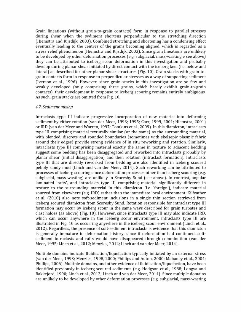
Grain lineations (without grain-to-grain contacts) form in response to parallel stresses during shear when the sediment shortens perpendicular to the stretching direction (Hiemstra and Rijsdijk, 2003). Combined stretching and shortening has a condensing effect eventually leading to the centres of the grains becoming aligned, which is regarded as a stress relief phenomenon (Hiemstra and Rijsdijk, 2003). Since grain lineations are unlikely to be developed by other deformation processes (e.g. subglacial, mass-wasting e see above) they can be attributed to iceberg scour deformation in this investigation and probably develop during planar shear initiated by direct contact with the iceberg keel (i.e. below and lateral) as described for other planar shear structures (Fig. 10). Grain stacks with grain-to-grain contacts form in response to perpendicular stresses as a way of supporting sediment (Iverson et al., 1996). However, since grain stacks in this investigation are so few and weakly developed (only comprising three grains, which barely exhibit grain-to-grain contacts), their development in response to iceberg scouring remains entirely ambiguous. As such, grain stacks are omitted from Fig. 10.
4.7. Sediment mixing
Intraclasts type III indicate progressive incorporation of new material into deforming sediment by either rotation (van der Meer, 1993; 1995; Carr, 1999, 2001; Hiemstra, 2001) or IRD (van der Meer and Warren, 1997; Tomkins et al., 2009). In this diamicton, intraclasts type III comprising material texturally similar (or the same) as the surrounding material, with blended, discrete and rounded boundaries (sometimes with skelsepic plasmic fabric around their edges) provide strong evidence of in situ reworking and rotation. Similarly, intraclasts type III comprising material exactly the same in texture to adjacent bedding suggest some bedding has been disaggregated and reworked into intraclasts probably by planar shear (initial disaggregation) and then rotation (intraclast formation). Intraclasts type III that are directly reworked from bedding are also identified in iceberg scoured pebbly sandy mud (Linch and van der Meer, 2014). Such reworking can be attributed to processes of iceberg scouring since deformation processes other than iceberg scouring (e.g. subglacial, mass-wasting) are unlikely in Scoresby Sund (see above). In contrast, angular laminated ‘rafts’, and intraclasts type III comprising material significantly different in texture to the surrounding material in this diamicton (i.e. ‘foreign’), indicate material sourced from elsewhere (e.g. IRD) rather than the immediate local environment. Kilfeather et al. (2010) also note soft-sediment inclusions in a single thin section retrieved from iceberg scoured diamicton from Scoresby Sund. Rotation responsible for intraclast type III formation may occur by iceberg scour in the same ways described for grain turbates and clast haloes (as above) (Fig. 10). However, since intraclasts type III may also indicate IRD, which can occur anywhere in the iceberg scour environment, intraclasts type III are illustrated in Fig. 10 as occurring anywhere in the iceberg scour environment (Linch et al., 2012). Regardless, the presence of soft-sediment intraclasts is evidence that this diamicton is generally immature in deformation history, since if deformation had continued, soft- sediment intraclasts and rafts would have disappeared through comminution (van der Meer, 1995; Linch et al., 2012; Menzies, 2012; Linch and van der Meer, 2014).
Multiple domains indicate fluidisation/liquefaction typically initiated by an external stress (van der Meer, 1993; Menzies, 1998, 2000; Phillips and Auton, 2000; Mahaney et al., 2004; Phillips, 2006). Multiple domains, and other evidence of fluidisation/liquefaction, have been identified previously in iceberg scoured sediments (e.g. Hodgson et al., 1988; Longva and Bakkejord, 1990; Linch et al., 2012; Linch and van der Meer, 2014). Since multiple domains are unlikely to be developed by other deformation processes (e.g. subglacial, mass-wasting
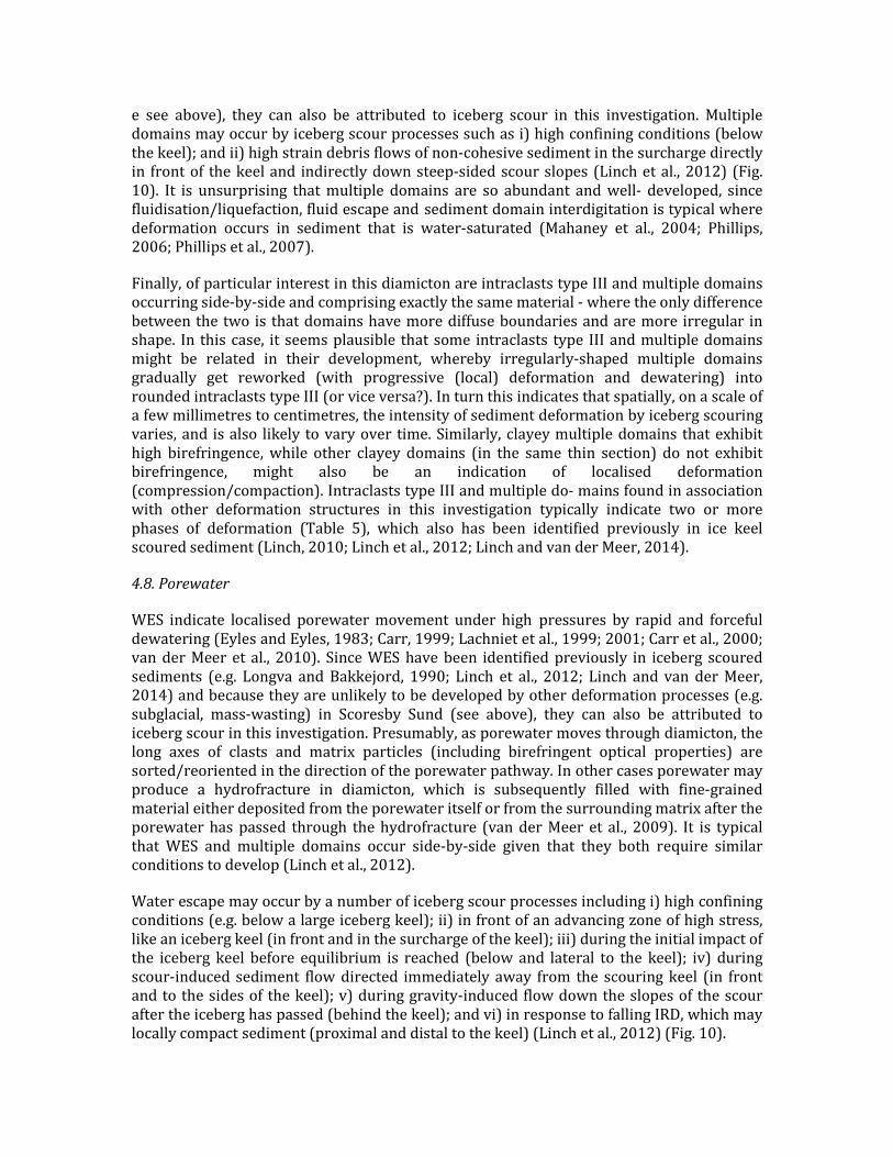
e see above), they can also be attributed to iceberg scour in this investigation. Multiple domains may occur by iceberg scour processes such as i) high confining conditions (below the keel); and ii) high strain debris flows of non-cohesive sediment in the surcharge directly in front of the keel and indirectly down steep-sided scour slopes (Linch et al., 2012) (Fig. 10). It is unsurprising that multiple domains are so abundant and well- developed, since fluidisation/liquefaction, fluid escape and sediment domain interdigitation is typical where deformation occurs in sediment that is water-saturated (Mahaney et al., 2004; Phillips, 2006; Phillips et al., 2007).
Finally, of particular interest in this diamicton are intraclasts type III and multiple domains occurring side-by-side and comprising exactly the same material - where the only difference between the two is that domains have more diffuse boundaries and are more irregular in shape. In this case, it seems plausible that some intraclasts type III and multiple domains might be related in their development, whereby irregularly-shaped multiple domains gradually get reworked (with progressive (local) deformation and dewatering) into rounded intraclasts type III (or vice versa?). In turn this indicates that spatially, on a scale of a few millimetres to centimetres, the intensity of sediment deformation by iceberg scouring varies, and is also likely to vary over time. Similarly, clayey multiple domains that exhibit high birefringence, while other clayey domains (in the same thin section) do not exhibit birefringence, might also be an indication of localised deformation (compression/compaction). Intraclasts type III and multiple do- mains found in association with other deformation structures in this investigation typically indicate two or more phases of deformation (Table 5), which also has been identified previously in ice keel scoured sediment (Linch, 2010; Linch et al., 2012; Linch and van der Meer, 2014).
4.8. Porewater
WES indicate localised porewater movement under high pressures by rapid and forceful dewatering (Eyles and Eyles, 1983; Carr, 1999; Lachniet et al., 1999; 2001; Carr et al., 2000; van der Meer et al., 2010). Since WES have been identified previously in iceberg scoured sediments (e.g. Longva and Bakkejord, 1990; Linch et al., 2012; Linch and van der Meer, 2014) and because they are unlikely to be developed by other deformation processes (e.g. subglacial, mass-wasting) in Scoresby Sund (see above), they can also be attributed to iceberg scour in this investigation. Presumably, as porewater moves through diamicton, the long axes of clasts and matrix particles (including birefringent optical properties) are sorted/reoriented in the direction of the porewater pathway. In other cases porewater may produce a hydrofracture in diamicton, which is subsequently filled with fine-grained material either deposited from the porewater itself or from the surrounding matrix after the porewater has passed through the hydrofracture (van der Meer et al., 2009). It is typical that WES and multiple domains occur side-by-side given that they both require similar conditions to develop (Linch et al., 2012).
Water escape may occur by a number of iceberg scour processes including i) high confining conditions (e.g. below a large iceberg keel); ii) in front of an advancing zone of high stress, like an iceberg keel (in front and in the surcharge of the keel); iii) during the initial impact of the iceberg keel before equilibrium is reached (below and lateral to the keel); iv) during scour-induced sediment flow directed immediately away from the scouring keel (in front and to the sides of the keel); v) during gravity-induced flow down the slopes of the scour after the iceberg has passed (behind the keel); and vi) in response to falling IRD, which may locally compact sediment (proximal and distal to the keel) (Linch et al., 2012) (Fig. 10).
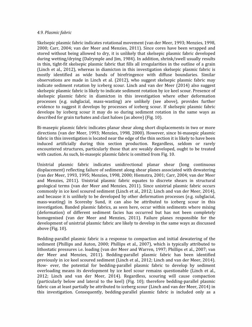
4.9. Plasmic fabric
Skelsepic plasmic fabric indicates rotational movement (van der Meer, 1993; Menzies, 1998, 2000; Carr, 2004; van der Meer and Menzies, 2011). Since cores have been wrapped and stored without being allowed to dry, it is unlikely that skelsepic plasmic fabric developed during wetting/drying (Dalrymple and Jim, 1984). In addition, shrink/swell usually results in thin, tight-fit skelsepic plasmic fabric that fills all irregularities in the outline of a grain (Linch et al., 2012), whereas in diamicton in this investigation skelsepic plasmic fabric is mostly identified as wide bands of birefringence with diffuse boundaries. Similar observations are made in Linch et al. (2012), who suggest skelsepic plasmic fabric may indicate sediment rotation by iceberg scour. Linch and van der Meer (2014) also suggest skelsepic plasmic fabric is likely to indicate sediment rotation by ice keel scour. Presence of skelsepic plasmic fabric in diamicton in this investigation where other deformation processes (e.g. subglacial, mass-wasting) are unlikely (see above), provides further evidence to suggest it develops by processes of iceberg scour. If skelsepic plasmic fabric develops by iceberg scour it may do so during sediment rotation in the same ways as described for grain turbates and clast haloes (as above) (Fig. 10).
Bi-masepic plasmic fabric indicates planar shear along short displacements in two or more directions (van der Meer, 1993; Menzies, 1998, 2000). However, since bi-masepic plasmic fabric in this investigation is located near the edge of the thin section it is likely to have been induced artificially during thin section production. Regardless, seldom or rarely encountered structures, particularly those that are weakly developed, ought to be treated with caution. As such, bi-masepic plasmic fabric is omitted from Fig. 10.
Unistrial plasmic fabric indicates unidirectional planar shear (long continuous displacement) reflecting failure of sediment along shear planes associated with dewatering (van der Meer, 1993, 1995; Menzies, 1998, 2000; Hiemstra, 2001; Carr, 2004; van der Meer and Menzies, 2011). Unistrial plasmic fabric equates to discrete shears in structural geological terms (van der Meer and Menzies, 2011). Since unistrial plasmic fabric occurs commonly in ice keel scoured sediment (Linch et al., 2012; Linch and van der Meer, 2014), and because it is unlikely to be developed by other deformation processes (e.g. subglacial, mass-wasting) in Scoresby Sund, it can also be attributed to iceberg scour in this investigation. Banded plasmic fabrics, as seen here, occur within sediments where mixing (deformation) of different sediment facies has occurred but has not been completely homogenised (van der Meer and Menzies, 2011). Failure planes responsible for the development of unistrial plasmic fabric are likely to develop in the same ways as discussed above (Fig. 10).
Bedding-parallel plasmic fabric is a response to compaction and initial dewatering of the sediment (Phillips and Auton, 2000; Phillips et al., 2007), which is typically attributed to lithostatic pressures i.e. loading (van der Meer and Warren, 1997; Phillips et al., 2007; van der Meer and Menzies, 2011). Bedding-parallel plasmic fabric has been identified previously in ice keel scoured sediment (Linch et al., 2012; Linch and van der Meer, 2014). How- ever, the potential for bedding-parallel plasmic fabric to develop by sediment overloading means its development by ice keel scour remains questionable (Linch et al., 2012; Linch and van der Meer, 2014). Regardless, scouring will cause compaction (particularly below and lateral to the keel) (Fig. 10); therefore bedding-parallel plasmic fabric can at least partially be attributed to iceberg scour (Linch and van der Meer, 2014) in this investigation. Consequently, bedding-parallel plasmic fabric is included only as a
potential structure that develops in response to iceberg scour (and therefore is highlighted in red in Fig. 10).
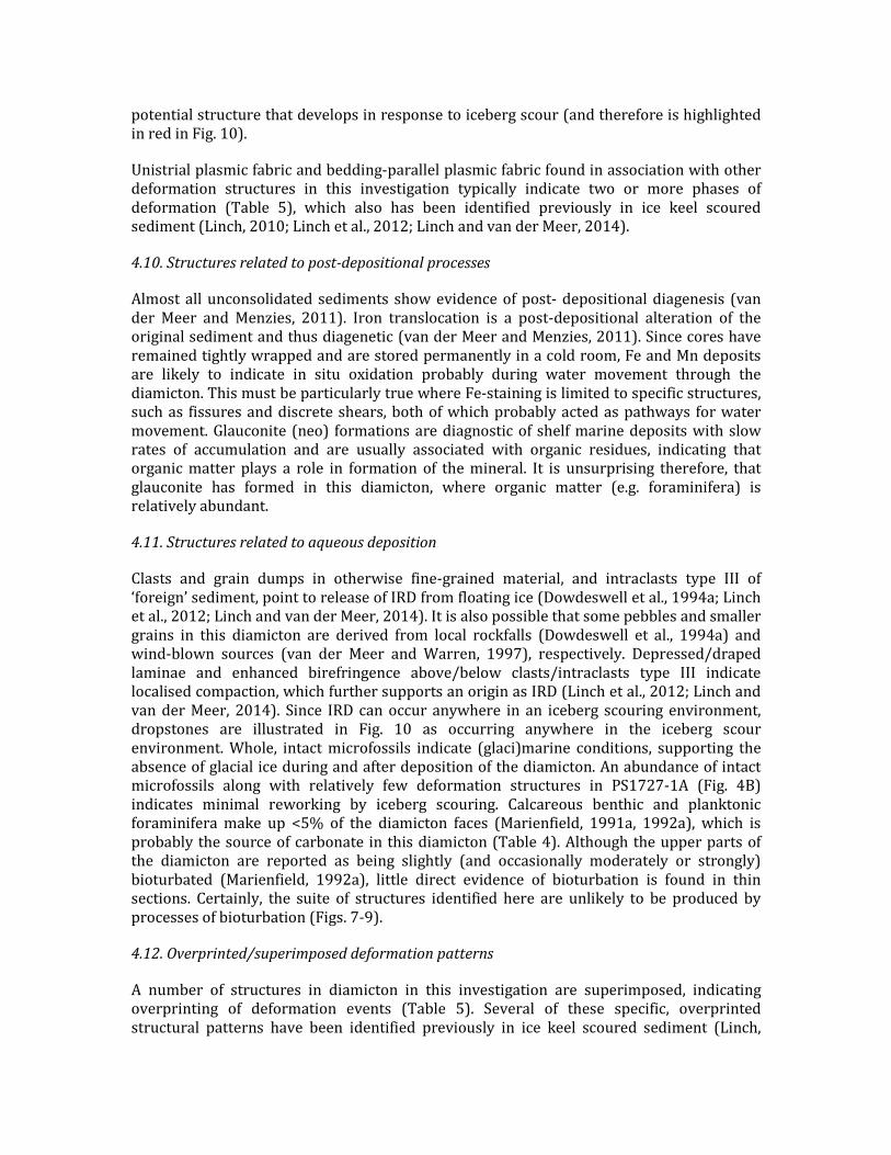
Unistrial plasmic fabric and bedding-parallel plasmic fabric found in association with other deformation structures in this investigation typically indicate two or more phases of deformation (Table 5), which also has been identified previously in ice keel scoured sediment (Linch, 2010; Linch et al., 2012; Linch and van der Meer, 2014).
4.10. Structures related to post-depositional processes
Almost all unconsolidated sediments show evidence of post- depositional diagenesis (van der Meer and Menzies, 2011). Iron translocation is a post-depositional alteration of the original sediment and thus diagenetic (van der Meer and Menzies, 2011). Since cores have remained tightly wrapped and are stored permanently in a cold room, Fe and Mn deposits are likely to indicate in situ oxidation probably during water movement through the diamicton. This must be particularly true where Fe-staining is limited to specific structures, such as fissures and discrete shears, both of which probably acted as pathways for water movement. Glauconite (neo) formations are diagnostic of shelf marine deposits with slow rates of accumulation and are usually associated with organic residues, indicating that organic matter plays a role in formation of the mineral. It is unsurprising therefore, that glauconite has formed in this diamicton, where organic matter (e.g. foraminifera) is relatively abundant.
4.11. Structures related to aqueous deposition
Clasts and grain dumps in otherwise fine-grained material, and intraclasts type III of ‘foreign’ sediment, point to release of IRD from floating ice (Dowdeswell et al., 1994a; Linch et al., 2012; Linch and van der Meer, 2014). It is also possible that some pebbles and smaller grains in this diamicton are derived from local rockfalls (Dowdeswell et al., 1994a) and wind-blown sources (van der Meer and Warren, 1997), respectively. Depressed/draped laminae and enhanced birefringence above/below clasts/intraclasts type III indicate localised compaction, which further supports an origin as IRD (Linch et al., 2012; Linch and van der Meer, 2014). Since IRD can occur anywhere in an iceberg scouring environment, dropstones are illustrated in Fig. 10 as occurring anywhere in the iceberg scour environment. Whole, intact microfossils indicate (glaci)marine conditions, supporting the absence of glacial ice during and after deposition of the diamicton. An abundance of intact microfossils along with relatively few deformation structures in PS1727-1A (Fig. 4B) indicates minimal reworking by iceberg scouring. Calcareous benthic and planktonic foraminifera make up <5% of the diamicton faces (Marienfield, 1991a, 1992a), which is probably the source of carbonate in this diamicton (Table 4). Although the upper parts of the diamicton are reported as being slightly (and occasionally moderately or strongly) bioturbated (Marienfield, 1992a), little direct evidence of bioturbation is found in thin sections. Certainly, the suite of structures identified here are unlikely to be produced by processes of bioturbation (Figs. 7-9).
4.12. Overprinted/superimposed deformation patterns
A number of structures in diamicton in this investigation are superimposed, indicating overprinting of deformation events (Table 5). Several of these specific, overprinted structural patterns have been identified previously in ice keel scoured sediment (Linch,
2010; Linch et al., 2012; Linch and van der Meer, 2014) (Table 5). Such combinations of ductile and brittle structures indicate a complex polyphase deformation history (Menzies, 2000; Phillips et al., 2007). In diamicton in this investigation, multiple phases of deformation are probably indicative of multiple, superimposed scour events since diamicton is likely to have been scoured, at the same location, multiple times e particularly in zones of HIS. However, the potential for multiple phases of deformation during one, single scour event cannot be dismissed particularly when sediment is deformed in front of, and later overridden by, the forward moving ice keel.
4.13. Diamicton underlying the fine laminated sediments
This investigation reveals that undated diamicton underlying the fine laminated sediments (thin section PS1718-1F) is similar in macro- and micromorphological texture and structure as diamicton deposited during the Holocene, which overlies the fine laminated sediments. Certainly, the suite of structures found in the diamicton underlying the fine laminated sediments is consistent with the suite of structures indicative of iceberg scouring rather than the suites of structures indicative of subglacial till or mass-wasting deposits (Table 3 and 6). These observations are also compatible with the observations by Dowdeswell et al. (1994b) and suggest that diamicton underlying the fine laminated sediments was probably also deposited by ice rafting and scouring during the Allerød Interstadial (~14-12 ka BP). This is incompatible with glacial ice in the fjord until 10 ka BP (Dowdeswell et al., 1994b). However, with the use of only one thin section (PS1718-1F) it would be prudent not to over-analyse these results. Indeed, interpretations should be based on analysis of multiple samples, not on individual thin section samples (van der Meer and Menzies, 2011).
5. Discussion
In the following sections iceberg-keel scouring deformation of diamicton is discussed in the context of the intensity of scouring (high-, intermediate- and low-intensity) (Table 3) and grain size, both of which are thought to influence the detectability, style and intensity of deformation. In addition, suites of deformation structures associated to i) subglacial tills, ii) mass-wasting deposits, iii) iceberg scouring in clays (from Linch et al., 2012), and iv) iceberg scouring in diamicton in this investigation, are compared (Table 6). The importance of recognising iceberg-keel scouring in the sedimentary record, but particularly in diamicton, also is discussed. Finally, readers are reminded of the value of micromorphology as a tool to examine the texture and structure of sediments in unprecedented detail.
5.1. High-, intermediate- and low-intensity iceberg scouring
In HIS zones in Scoresby Sund there is a wider variety of types of microstructures than in IIS and LIS zones (Table 3). In addition, microstructures are more frequently identified and distributed (i.e. throughout cores), more abundant (i.e. quantities) and generally better developed (i.e. in strength), than in IIS and LIS zones (Table 3). Although IIS and LIS zones are only represented by five samples whilst twelve samples were taken from HIS zones, such marked differences in the type, frequency/distribution, abundance and development of structures in the different zones of iceberg scour intensity provide compelling evidence in favour of emerging patterns in the data (Table 3). First, there are considerably fewer rotation, compression and slump structures noted in IIS and LIS zones. For example, grain turbates are almost entirely absent from IIS and LIS zones, whereas they are identified relatively frequently (albeit in low abundance and development) in HIS zones (Table 3). In
addition, folds, sheath folds and realigned bedding are well- developed and reasonably abundant in HIS zones, whereas they are absent altogether in IIS and LIS zones (Table 3). Similarly, there are considerably fewer well-developed planar shear structures in IIS and LIS zones. This is particularly obvious where discrete shears are reasonably abundant, often well-developed and frequently identified throughout cores in HIS zones, but are noted much less in IIS and LIS zones (Table 3). A similar pattern exists for multiple domains (evidence of sediment mixing), which are abundant, well- developed and frequently identified throughout cores in HIS zones, whereas they are fewer in IIS and LIS zones (Table 3). WES, bedding-parallel plasmic fabric and dropstones are also limited in IIS and LIS zones (Table 3). Finally, greater reworking of sediment by iceberg keels in HIS zones, and thus aeration (and oxidation) of the diamicton, probably explains why there is more Fe/Mn residue in HIS zones compared to IIS and LIS zones (Table 3). Particularly compelling is the lack of structures in core PS1719-1 (Table 3), retrieved from deeper water LIS zones (Marienfield, 1992a; Dowdeswell et al., 1993). Core PS1719-1 (thin section PS1719-1A: Fig. 4C) is the only core that does not show evidence of discrete shears and multiple domains, while all other cores do.
While discrepancies in the type, frequency/distribution, abundance and development of some structures may be partly explained by local variations in grain size (discussed below), a more obvious reason why there are more, well-developed structures in HIS zones compared to IIS and LIS zones in Scoresby Sund is because HIS zones have been subjected (by definition) to higher intensities of iceberg scouring. It follows that diamicton in HIS zones was subjected to more frequent, probably multiple/superimposed, scour events (i.e. stress) and thus generally higher strains than IIS and LIS zones. This also supports Linch et al. (2012), who note higher strain deformation patterns in sediment scoured multiple times. How- ever, strains were not so high in HIS zones that diamicton was entirely reworked and/or homogenised, otherwise there would be very few remaining intact structures (Menzies, 2012). The presence of soft-sediment intraclasts (type III), for example, remains evidence that sediment is generally immature in deformation history (van der Meer, 1995; Linch et al., 2012; Menzies, 2012; Linch and van der Meer, 2014). Regardless, results from this investigation, which suggest deformation in HIS zones is generally more intense than in IIS and LIS zones, directly supports the initial classification of iceberg scour intensity zones on acoustic records as proposed by Dowdeswell et al. (1993) (Table 1). This demonstrates how large- (acoustic) and small-scale (micromorphology) techniques can be used complementary to each other as a way to strengthen interpretations. In addition, it means that where broad-scale contextual information is lacking, micromorphology provides an invaluable tool for examining sediments.
5.2. The influence of grain size on ice keel scour deformation
Ice keel scour has been investigated macro- and microscopically in different grain sizes including laminated clays from Glacial Lake Agassiz, Manitoba (Linch et al., 2012), and pebbly sandy mud and fine-grained sands from Scarborough Bluffs, Ontario (Linch and van der Meer, 2014). Linch and van der Meer (2014) note that although ice keel scoured laminated clays, pebbly sandy mud and fine- grained sands all share a similar suite of deformation structures, notable differences can be identified, which may be partly a function of grain size. Certainly, the potential for grain size and sorting of grains to affect the strength and strain response of sediment (in terms of permeability and frictional properties) may in turn affect the detectability, style and intensity of deformation structures, regardless of changing or variable stress levels (e.g. size, shape, density, mass

etc. of the original stress applicator) (Linch and van der Meer, 2014). Where different grain sizes occur side-by-side (as they do in diamicton in this investigation), even under the same moisture conditions, there might be different responses to stress (van der Meer and Menzies, 2011). The current investigation examines, for the first time, iceberg scour in diamicton, which provides additional information about the influence of grain size on ice keel scour deformation.
Several structural observations in diamicton in this investigation are likely to be partially related to grain size. For example, noticeably deformed clayey laminae (in otherwise macroscopically massive diamicton) in this investigation, is probably attributable to deformation partitioning (Benn and Evans, 1996), which focuses deformation into particular lithologies or horizontal zones - particularly fine-grained sediment that is known to facilitate deformation (Phillips, 2006). Sediment comprising coarser constituents, such as the diamicton (i.e. ‘poorly sorted sediment comprising a variety of grain sizes’) examined in this investigation, generally exerts higher grain-to-grain friction, is better drained and subsequently is higher in shear strength than sediment comprising finer-grained constituents (Linch and van der Meer, 2014). This probably also partly ex- plains why overall there are so few ductile deformation structures (e.g. folds) and porewater structures (e.g. water escape and flow), identified in diamicton in this investigation (Linch and van der Meer, 2014) (Table 3). Similarly, (full or half eye-shaped) augen-shapes (reflecting planar shear), tend to develop where coarse-grained sediment facilitates drainage and is thus more conducive to brittle fracture and planar shear than finer-grained sediment (Linch and van der Meer, 2014). In this investigation, augen-shapes tend to develop in sandier parts of the diamicton (Fig. 8I). In addition, processes of fluidisation and remobilisation mainly affect silt and sand fractions (Phillips et al., 2007), which probably explains why so many well-developed multiple domains are noted in diamicton in this investigation, which is very silty (~35-76%) and sometimes quite sandy (~3-48%).
As well as affecting the strength and strain response of sediment, grain size determines which structures develop regardless of post-depositional processes (Linch and van der Meer, 2014). Well- laminated sediment allows the development and identification of folds and faults whereas a sediment with a more ‘massive’ structure will not, regardless of whether it has been subjected to compression/slump and planar shear or not (Linch and van der Meer, 2014). This may partly explain why there are so few folds and faults in diamicton in this investigation and why discrete shears (which are the equivalent of faults where layers/bedding are absent) are so abundant (Table 3). WES are also more likely to be identified where they disrupt sedimentary layers (e.g. Linch et al., 2012). The lack of sedimentary layers in diamicton in this investigation might partly explain why so few WES can be seen, and why realigned bedding is not more common, regardless of whether diamicton has been subject to porewater processes or reorientation, respectively, or not. Certainly, where samples were taken across sand layers in this investigation (e.g. PS1716-2B), realigned bedding is noticeable (Fig. 7C). Similarly, crudely-bedded material provides contrasting marker horizons (in texture and colour) in which augen-shapes can be identified (Linch and van der Meer, 2014). Lack of such obvious marker horizons in diamicton in this investigation might partly explain why augen-shapes are so few, regardless of whether diamicton underwent planar shear or not (Linch and van der Meer, 2014). In this investigation, several different diamicton ‘zones’ (based on texture and colour), also act as ‘markers’, and are identified easily side-by-side or where they are mixed together. This might partly explain why multiple domains are so abundant and well-developed in this investigation since domains would not be as easily identified if diamicton

texture did not vary at all (regardless of whether it was mixed or not).
In addition, the availability of sand-sized grains partly determines the abundance and development of grain-related structures (Linch and van der Meer, 2014). Grain turbates, for example, are noted several times in diamicton in this investigation, where grain content is relatively high (Fig. 8A and B). In contrast, grain turbates are absent entirely from iceberg scoured laminated clays (Linch et al., 2012) and are only ambiguously identified in ice keel scoured pebbly sandy mud (Linch and van der Meer, 2014), where grain availabilities are considerably lower than in diamicton examined in this investigation. Similarly, relatively consistent identification of skelsepic plasmic fabric in diamicton in this investigation probably partly reflects availability of grains (Fig. 8W and X). Grain lineations (Fig. 8L), which have not been identified previously in ice keel scoured sediment (Linch et al., 2012; Linch and van der Meer, 2014), must partly be attributable to the high number of available grains in diamicton in this investigation too, particularly where samples are taken across sand layers (e.g. PS1716-1A). Finally, plasmic fabrics will develop only where clay- sized particles are available (Menzies, 2012; Linch and van der Meer, 2014). Since diamicton in this investigation comprises clay contents as low as ~13-23% it is no surprise that plasmic fabrics are not as abundant and as well-developed as they were in, for example, iceberg scoured clays from Glacial Lake Agassiz (Linch et al., 2012). Grain size is also likely to affect the detectability, style and intensity of superimposed, overprinted structures (Table 5). Regardless, a dominant suite of deformation structures develops in response to ice keel scour processes independent of grain size (see below: Table 6).
5.3. Differentiating subglacial, mass-wasting and iceberg scour deformation
Linch et al. (2012) presented for the first time a comparison of the microstructures present in subglacial tills, mass-wasting de- posits and iceberg scoured clays. The current investigation builds on the original work of Linch et al. (2012) by adding into this comparison, the microstructures in iceberg scoured diamicton (Table 6). In addition, the current investigation, and information from Linch and van der Meer (2014), helps to inform the content of Table 6 by providing sufficient evidence to suggest first, that clast haloes and bedding-parallel plasmic fabric potentially develop in response to iceberg scour in both clays and diamicton (now indicated by a ‘?’ in Table 6); and secondly, that skelsepic plasmic fabric is likely to develop partly in response to iceberg scour in clays (now indicated by a ‘?’ in Table 6) (cf. Linch et al., 2012; Linch and van der Meer, 2014).
Clearly, many of the differences between the suites of structures found in iceberg scoured clays and diamicton (Table 6) are a function of grain size, as described above (e.g. presence of grain turbates). However, processes of multiple iceberg scour, and thus increased sediment reworking (particularly in HIS zones) in Scoresby Sund, may explain increases in the development of some microstructures in iceberg scoured diamicton in this investigation (e.g. intraclasts type III). Despite these minor differences, it is clear that the suites of microstructures associated with iceberg scour, in both clays and diamicton, are distinctly different from the suites of microstructures found in subglacial tills and mass-wasting deposits (Table 6) (cf. Kilfeather et al., 2010). In iceberg scoured sediments rotation/ductile deformation is dominated by folds and realigned bedding; planar/brittle deformation is dominated by faults and discrete shears; sediment mixing is dominated by intraclasts type III and multiple domains; porewater is dominated by water escape and flow; and plasmic fabric is dominated by unistrial plasmic fabric (Table 6). In general, iceberg scour sediment deformation remains dominated by planar/brittle deformation, sediment mixing and
porewater processes, regardless of grain size (Table 6). This contrasts with subglacial till and mass-wasting deposits that are instead dominated by (a wider variety of) rotational/ductile and planar/brittle structures, including a range of plasmic fabrics (Table 6). Finally, dropstones are notably abundant in all iceberg scoured sediments, but remain rare in subglacial tills and mass-wasting deposits (Table 6).
Visual comparison of ‘sets’ of microstructures in this way permit differentiation or co-association of sediments from the same or different sedimentary environments (van der Meer and Menzies, 2011). This non-statistical, subjective method is successful when clear and marked differences between microstructure ‘sets/suites’ are clearly discernible e as they are in Table 6 - especially when coupled with other data such as the geomorphic context, clast provenance or the presence of features diagnostic of specific environments (van der Meer and Menzies, 2011).
5.4. Wider context
The specific suite of microstructures (in combination with macroscale context wherever possible) identified in the current investigation, now provides a means of identifying and characterising widespread iceberg rafted and scoured diamicton in both modern and ancient sedimentary environments. This suite of microstructures is crucial for distinguishing iceberg scoured diamicton from diamicton developed and deformed by other processes (e.g. ice-shelf basal processes, subglacial deposition, grounding-zone wedges, mass-wasting etc.). It may even lead to the re-interpretation of sediments that previously have been assigned a subglacial origin, providing new insights into ice-sheet and glacier reconstructions (Gilbert et al., 1992; Dowdeswell et al., 1993, 1994a,b; Eden and Eyles, 2001; Woodworth-Lynas and Guigné,2003;Linchetal.,2012). In addition, since fast-flowing outlet glaciers and ice streams are the principal source of icebergs and IRD entering the marine environment (Ó Cofaigh et al., 2001), such facies (in the modern and ancient glacimarine sedimentary record) could be indicative of the presence and role of outlet glaciers and ice streams in draining large palaeo-ice masses. This holds major implications for reconstructing the geometry and dynamics of former ice sheets (Dowdeswell et al., 1994a; Ó Cofaigh et al., 2001), and ultimately, environmental change. Finally, the information from this investigation is also likely to be relevant to inform the safe installation, and protection, of offshore structures (e.g. pipelines), where iceberg scouring presents a geohazard (e.g. Palmer and Chan, 2012).
5.5. The value of micromorphology
Through examining thin sections of iceberg scoured diamicton in this investigation, micromorphology has permitted the internal arrangement of all sedimentological components to be observed in quite a large number of samples (van der Meer and Menzies, 2011). This has allowed some general statements about the micro- architecture of iceberg scoured diamicton to be made, to gain an understanding of the processes involved in the deformation of diamicton by iceberg-keel scouring (van der Meer and Menzies, 2011). Here we establish a link between a particular suite of microstructures in diamicton and known iceberg scour mechanical processes, which will allow the recognition of iceberg scouring in diamicton in outcrop and especially in cores where the wider context of the sediment is less clear (van der Meer and Menzies, 2011).
In the absence of macroscopic sediment exposures/outcrops the current study emphasises
the value of micromorphology as a means of examining, in detail, sediment cores. Significantly, diamicton examined from cores in this investigation was described previously as ‘massive’, ‘structureless’ and ‘homogenous’ as a function of intensive reworking by iceberg keels (Dowdeswell et al., 1994a,b). However, the current micromorphological investigation demonstrates that where sediment appears ‘massive’, ‘structure- less’ or ‘homogenous’ at the macroscale, the same is very often not the case at the microscale. Certainly, it has been many years now since the term ‘glacial diamicton’ conjured an image of a massive, featureless unit due to the role of micromorphology (Menzies et al., 2010). It follows that the term ‘macroscopically massive/structureless/homogenous’ ought to be adopted instead, and the potential for sediments to contain valuable textural and structural information at the microscale should not be overlooked. Only micromorphology provides an insight into both matrix/plasma and skeletal grains and their mutual arrangement and structural attributes, where other methods do not allow an inspection of the relationships between the constituent particles (Menzies et al., 2010).
Micromorphology is not without its limitations, however (e.g. Leighton et al., 2012; Lea and Palmer, 2014; Bendle et al., 2015), but the information that has been gleaned from thin sections of un- consolidated sediments in this and other investigations (see Figs. 7-9), including human-made materials such as concrete and mortar (Menzies et al., 2010; van der Meer and Menzies, 2011 - and references within), is undeniable. In addition, quantification of microstructures (Carr and Goddard, 2008; Menzies and Whiteman, 2009; Patel, 2011; van der Meer and Menzies, 2011; Linch and van der Meer, 2013; Neudorf et al., 2013; Lea and Palmer, 2014; Narloch et al., 2015) and new methods in ‘microstructural mapping’ (Phillips et al., 2011; Gehrmann et al., 2016), are developing with promising results. Finally, in combination with thin sections, 3D microtomography studies of microstructures (Kilfeather and van der Meer, 2008; Tarplee et al., 2011; Bendle et al., 2015; Groves, in prep) and development of the Metripol microscope system to automatically measure and record birefringence (Linch and van der Meer, 2013; Hiemstra and Carr, in prep) should be even more rewarding.
6. Conclusions
• Diamicton in this investigation is characterised by a number of deformation structures attributable to (direct/indirect) mechanical iceberg scour processes including: sub-horizontal microfabrics, grain turbates, folds, sheath folds, realigned bedding, augen-shapes, normal faults, discrete shears, grain lineations, intraclasts type III, multiple domains, water escape structures, skelsepic plasmic fabric, unistrial plasmic fabric (including banded plasma) and dropstones. In addition, a suite of complex overprinted structures, indicating at least two phases of sediment deformation in the diamicton, is identified. Presence of both ductile and brittle structures in iceberg scoured diamicton indicates a complex polyphase deformation history.
• This suite of microstructures is distinctly different from the suites of microstructures related to subglacial tills and mass- wasting deposits (Table 6), and can now be used to identify iceberg scoured diamicton in both the modern and ancient glacimarine sedimentary record in outcrop and especially in cores. Such facies, implying the presence of large numbers of deep-keeled icebergs, could be indicative of the presence of fast- flowing outlet glaciers or ice streams draining large ice masses, with implications for reconstructing the dynamics and extents of former ice sheets.
• Structures that are identified in diamicton in this investigation but cannot necessarily be assigned to processes of iceberg scouring include clast haloes and bedding-parallel plasmic fabric (highlighted as red in Fig. 10). Grain stacks and (bi) masepic plasmic fabric cannot be attributed to iceberg scour processes in diamicton in this investigation because both structures are seldom or rarely encountered, weakly developed and ambiguous in their development and/or origins in this investigation.
• Although the grain size of diamicton partially affects the detectability, style and intensity of deformation structures in response to iceberg scouring, iceberg scoured diamicton re- mains dominated by planar/brittle deformation, sediment mixing and high porewater, and dropstones. This is consistent with observations made in iceberg scoured clays from Glacial Lake Agassiz and ice keel scoured pebbly sandy mud and fine- grained sands from Scarborough Bluffs (Linch et al., 2012; Linch and van der Meer, 2014). Therefore, regardless of the grain size, the suite of microstructures identified in iceberg scoured sediments is generally consistent.
• The iceberg-keel scouring environment is highly complex, comprising deformation i) distal to the iceberg keel; ii) lateral and in front of the iceberg keel (in the surcharge and beyond it); iii) directly below the iceberg keel; and iv) in the scour behind the iceberg keel after the keel has passed.
• High-intensity iceberg scour (HIS) zones in Scoresby Sund are characterised by i) a wider variety of types of structures; ii) more frequently identified and distributed structures (i.e. throughout cores); iii) more abundant structures (i.e. quantities); and iv) better developed structures (i.e. in strength), than intermediate- intensity iceberg scour (IIS) and low-intensity iceberg scour (LIS) zones in Scoresby Sund. This is probably because HIS zones were subjected to more frequent, multiple/superimposed scour events (i.e. stress) and thus higher strains than IIS and LIS zones.
• The value of micromorphology as a means of examining sediment texture and structure in great detail is clear. It is particularly relevant in the detailed examination of sediment cores, when outcrops do not exist. Here micromorphology demonstrates that sediment previously described as ‘massive’ is in fact far from massive under the microscope. Therefore, ‘massive’ sediment at the macroscale is in reality ‘macroscopically massive’. Understanding this implies that the potential for sediments to contain extremely valuable textural and structural information at the microscale should not be overlooked.
Acknowledgements
This research was primarily funded by the University of Brighton's ‘Rising Stars Initiative’ and the ‘School of Environment and Technology Research Investment Fund’, with supplementary funds awarded by the Quaternary Research Association. The funding sources had no involvement in study design, in collection, analysis and interpretation of data, in the writing of the article and in the decision to submit the article for publication. Special thanks go to Hannes Grobe (Alfred Wegener Institute) for permission to examine and sample sediment cores. Thanks also to Johann Phillip Klages (Alfred Wegener Institute) for his hospitality and guidance; Kelly Hogan (British Antarctic Survey) for assistance with examining Parasound records; Adrian Palmer (Royal Holloway University of London) for thin section production; and Pete Lyons, Magdalena Grove and Paul Kilkie (University of Brighton) for help in the lab- oratory. Final thanks to Emrys Phillips (British Geological
Survey) for reviewer comments.
References
Anderson, J.B., Domack, E.W., Kurtz, D.D., 1980. Observations of sediment laden icebergs in Antarctic waters: implications to glacial erosion and transport. J. Glaciol. 25, 387-396.
Anderson, J.B., 1999. Antarctic Marine Geology. Cambridge University Press, Cambridge, UK. Anderson, J.B., Kennedy, D .S., Sm ith 991. Sedimentary facies associated with Antarctica's floating ice masses. In: Anderson, J.B., Ashley, G.M. (Eds.), Glacial Marine Sedimentation: Palaeoclimatic Significance, vol. 261. Geological Society of America, pp. 1-25. Special Paper.
Barker, A., Timco, G., 2002. Laboratory experiments of ice scour processes: rigid ice indentor. Cold Regions Sci. Technol. 35, 195-206.
Barker, A., Timco, G., 2003. Laboratory experiments of ice scour processes; buoyant ice model. Cold Regions Sci. Technol. 36, 103-114.
Been, K., Sancio, R.B., Ahrabian, A., van Kesteren, W., Croasdale, K., Palmer, A.C., 2008. Subscour displacement in clays from physical model tests. In: Proceedings, 7th International Pipeline Conference, Calgary. Paper IPC 2008-64186.
Bendle, J.M., Palmer, A.P., Carr, S.J., 2015. A comparison of micro-CT and thin section analysis of late glacial glaciolacustrine varves from Glen Roy. Quat. Sci. Rev. 114, 61-77.
Benn, D.I., Evans, D.J.A., 1996. The recognition and interpretation of subglacially deformed materials. Quat. Sci. Rev. 15, 23-52.
Brady, N.C., Weil, R.R., 1999. The Nature and Properties of Soils, twelveth ed. Prentice Hall Inc., New Jersey.
Brewer, R., 1976. Fabric and Mineral Analysis of Soils. Krieger, Huntington.
Carr, S.J., 1999. The micromorphology of Last Glacial Maximum sediments in the southern North Sea. Catena 35, 123-145.
Carr, S.J., 2001. Micromorphological criteria for discriminating subglacial glaci-marine sediments: evidence from a contemporary tidewater glacier, Spitsbergen. Quat. Int. 86, 71-79.
Carr, S.J., 2004. Microscale features and structures. In: Evans, D.J.A., Benn, D.I. (Eds.), A Practical Guide to the Study of Glacial Sediments. Oxford University Press, New York, pp. 115-144.
Carr, S.J., Lee, J.A., 1998. Thin section production of diamicts: problems and solutions. J. Sediment. Res. 68, 217-221.
Carr, S.J., Rose, J., 2003. Till fabric patterns and significance: particle response to
subglacial stress. Quat. Sci. Rev. 22, 1415-1426.
Carr, S.J., Goddard, M.A., 2008. Role of particle size in till-fabric characteristics: systematic variation in till fabric from Vestari-Hagafellsjo"kull, Iceland. Boreas 36 (4), 371-385.
Carr, S.J., Haflidason, H., Sejrup, H.P., 2000. Micromorphological evidence supporting Late Weichselian glaciation of the northern North Sea. Boreas 29, 315-328.
Dalrymple, J.B., Jim, C.Y., 1984. Experimental study of soil microfabrics induced by isotropic stresses of wetting and drying. Geoderma 34, 43-68.
Dowdeswell, J.A., Dowdeswell, E.K., 1989. Debris in icebergs and rates of glaci- marine sedimentation: observations from Spitsbergen and a simple model. J. Geol. 97, 221-231.
Dowdeswell, J.A., Ottesen, D., 2013. Buried iceberg ploughmarks in the Early Quaternary sediments of the central North Sea: a two-million year record of glacial influence from 3D seismic data. Mar. Geol. 344, 1-9.
Dowdeswell, J.A., Villinger, H., Whittington, R.J., Marienfield, P., 1991. The Quaternary marine record in the Scoresby Sund fjord system, East Greenland: preliminary results and interpretation. In: Moller, P., et al. (Eds.), The Last Interglacial-glacial Cycle: Jameson Land and Scoresby Sund, East Greenland, vol. 33, pp. 149-155. Lunqua Report Series.
Dowdeswell, J.A., Whittington, R.J., Hodgkins, R., 1992. The sizes, frequencies and freeboards of East Greenland icebergs observed using ship radar and sextant. J. Geophys. Res. 97, 3515-3528.
Dowdeswell, J.A., Villinger, H., Whittington, R.J., Marienfield, P., 1993. Iceberg scouring in Scoresby Sund and on the East Greenland continental shelf. Mar. Geol. 111, 37-53.
Dowdeswell, J.A., Whittington, R.J., Marienfield, P., 1994a. The origin of massive diamicton facies by iceberg rafting and scouring, Scoresby Sund, East Greenland. Sedimentology 41, 21-35.
Dowdeswell, J.A., Uenzelmann-Neben, G., Whittington, R.J., Marienfield, P., 1994b. The Late Quaternary sedimentary record in Scoresby Sund, East Greenland. Boreas 23, 294-310.
Dowdeswell, J.A., Batchelor, C.L., Hogan, K.A., Schenke, H.-W., 2016. Nordvestfjord: a major East Greenland fjord system. In: Dowdeswell, J.A., Canals, M., Jakobsson, M., Todd, B.J., Dowdeswell, E.K., Hogan, K.A. (Eds.), Atlas of Submarine Glacial Landforms: Modern, Quaternary and Ancient, vol. 46. Geological Society, Memoirs, London, pp. 43-44.
Eden, D.J., Eyles, N., 2001. Description and numerical model of Pleistocene iceberg scours and ice-keel turbated facies at Toronto, Canada. Sedimentology 48 (5), 1079-1102.
Enderlin, E.M., Howat, I.M., 2013. Submarine melt rate estimates for floating termini of
Greenland outlet glaciers (2000-2010). J. Glaciol. 59 (213), 67-75.
Eyles, C.H., Eyles, N., 1983. Sedimentation in a large lake: a reinterpretation of the Late Pleistocene stratigraphy at Scarborough Bluffs, Ontario, Canada. Geology 11, 146-152.
Eyles, N., Clark, B.M., 1988. Storm influenced deltas and ice-scouring in a Late Pleistocene glacial lake. Geol. Soc. Am. Bull. 100, 793-809.
Eyles, N., Meulendyk, T., 2008. Ground-penetrating radar study of Pleistocene ice scours on a glaciolacustrine sequence boundary. Boreas 10, 1-8.
Eyles, N., Eyles, C.H., Gostin, V.A., 1997. Iceberg rafting and scouring in the Early Permian shoalhaven group of New South Wales, Australia: evidence of heinrich-like events? Palaeogeogr. Palaeoclimatol. Palaeoecol. 136, 1-17.
Eyles, N., Eyles, C., Woodworth-Lynas, C.M.T., Randall, T., 2005. The sedimentary record of drifting ice (Early Wisconsin Sunnybrook deposit) in an ancestral ice- dammed Lake Ontario, Canada. Quat. Res. 63, 171-181.
Evans, D.J.A., Phillips, E.R., Hiemstra, J.F., Auton, C.A., 2006. Subglacial till: formation, sedimentary characteristics and classification. Earth Sci. Rev. 78, 115-176.
Funder, S., 1972. Deglaciation of the Scoresby Sund fjord region north-east Greenland. Inst. Br. Geogr. Special Publ. 4, 33-42.
Funder, S., 1978. Holocene stratigraphy and vegetation history in the Scoresby Sund area, East Greenland. Grønlands geologiske undersøgelse. Bulletin 129, 66.
Funder, S., Kjeldson, K.K., Kjær, K.H., Ó Cofaigh, C., 2011. The Greenland Ice Sheet during the past 300, 000 years: a review. In: Ehlers, J., Gibbard, P.L., Hughes, P.D. (Eds.), Developments in Quaternary Science, vol. 15, pp. 699-713.
Gehrmann, A., Hüneke, H., Meschede, M., Phillips, E., 2016. 3D microstructural architecture of deformed glacigenic sediments associated with large-scale glaci-tectonism, Jasmund Peninsula (NE Rügen), Germany. J. Quat. Sci. http://dx.doi.org/10.1002/jqs.2843.
Gilbert, G.R., Handford, K.J., Shaw, J., 1992. Ice scours in the sediments of Lake Ir-oquois, Prince Edward County, eastern Ontario. Geogr. Physique Quaternaire 46, 189-194.
Grobe, H., 1987. A simple method for the determination of ice-rafted debris in sediment cores. Polarforschung 57, 123-126.
Groves, J., in prep. Quantifying 3D Micro-fabric in Tills Using X-ray mCT. PhD thesis, Queen Mary University of London.
Håkansson, L., Briner, J., Alexandersson, H., Aldahand, A., Possnerte, G., 2007. 10Be ages from central East Greenland constrain the extent of the Greenland Ice Sheet during the Last Glacial Maximum. Quat. Sci. Rev. 26, 2316-2321.
Hiemstra, J.F., 2001. Microscopic analyses of Quaternary glacigenic sediment of Marguerite Bay, Antarctic Peninsula. Arctic. Antarct. Alp. Res. 33, 258-265.
Hiemstra, J.F., van der Meer, J.J.M., 1997. Porewater controlled grain fracturing as an indicator for subglacial shearing in tills. J. Glaciol. 43 (145), 446-454.
Hiemstra, J.F., Rijsdijk, K.F., 2003. Observing artificially induced strain: implications for subglacial deformation. J. Quat. Sci. 18 (5), 373-383.
Hiemstra, J.F., Carr, S.J., in prep. The development of subglacial shear zone geome-tries revealed by Metripol automated birefringence imaging.
Hodgson, G.J., Lever, J.H., Woodworth-Lynas, C.M.T., Lewis, C.F.M., 1988. The Dynamics of Iceberg Grounding and Scouring (DIGS Experiment and Repetitive Mapping of the Eastern Canadian Continental Shelf). Environmental Studies Research Funds, Ottawa. Report No. 094.
Iverson, N.R., Hooyer, T.S., Hooke, R.L., 1996. A laboratory study of sediment deformation: stress heterogeneity and grain-size evolution. Ann. Glaciol. 22, 169-175.
Josenhans, H., 1987. Icebergs scour the ocean floor. GEOS 16 (4), 1-5. Josenhans, H .W ., Zevenhuizen, J., Klassen, R.A., 1986. The Quaternary geology of the Labrador shelf. Can. J. Earth Sci. 23, 1190-1213.
Kilfeather, A.A., van der Meer, J.J.M., 2008. Pore size, shape and connectivity in tills and their relationship to deformation processes. Quat. Sci. Rev. 27 (3-4), 250-266.
Kilfeather, A.A., Ó Cofaigh, C., Dowdeswell, J.A., van der Meer, J.J.M., Evans, D.J.A., 2010. Micromorphological characteristics of glacimarine sediments: implica- tions for distinguishing genetic processes of massive diamicts. Geo-Marine Lett. 30, 77-97.
Koch, L., 1945. The East Greenland ice. Meddelelser Grønl. 130, 373.
Laberg, J.S., Vorren, T.O., 2000. Flow behaviour of the submarine glacigenic debris flows on the Bear Island trough mouth fan, western Barents Sea. Sedimentology 47, 1105-1117.
Lachniet, M.S., Larson, G.J., Strasser, J.C., Lawson, D.E., Evenson, E.B., Alley, R.B., 1999. Microstructures of glacigenic sediment-flow deposits Matanuska Glacier, Alaska. In: Mickleson, D.M., Attig, J.W. (Eds.), Glacial Processes Past and Present. Geological Society of America Special Paper 337, Bolder, Colorado, pp. 45-57.
Lachniet, M.S., Larson, G.J., Lawson, D.E., Evenson, E.B., Alley, R.B., 2001. Micro-structures of sediment flow deposits and subglacial sediments: a comparison. Boreas 30, 254-262.
Lea, J.M., Palmer, A.P., 2014. Quantification of turbate microstructures through subglacial till: dimensions and characteristics. Boreas 43, 869-881.
Lee, J., Kemp, R., 1993. Thin Sections of Unconsolidated Sediments and Soils: A Recipe. Department of Geography, Royal Holloway University of London, London.

Leighton, I.D., Hiemstra, J.F., Weidemann, C.T., 2012. Recognition of micro-scale deformation structures in glacial sediments - pattern perception, observer bias and the influence of experience. Boreas 42, 463-469.
Lien, R., Solheim, A., Elverhøi, A., Rokoengen, K., 1989. Iceberg scouring and sea bed morphology on the eastern Weddel Sea shelf, Antarctica. Polar Res. 7, 43-57.
Linch, L.D., 2010. Micromorphology of Iceberg Scour. Ph.D. thesis. Queen Mary University of London.
Linch, L.D., van der Meer, J.J.M., 2013. Metripol birefringence imaging of uncon- solidated glaciotectonised and ice keel scoured sediments: identification of unistrial plasmic fabric. Boreas 42, 678-692.
Linch, L.D., van der Meer, J.J.M., 2014. Micromorphology of ice keel scour in pebbly sandy mud and fine-grained sands: Scarborough Bluffs, Ontario, Canada. Sedimentology 62, 110-129.
Linch, L.D., van der Meer, J.J.M., Menzies, J., 2012. Micromorphology of iceberg scour in clays: Glacial Lake Agassiz, Manitoba, Canada. Quat. Sci. Rev. 55, 125-144.
Longva, O., Bakkejord, K.J., 1990. Iceberg deformation and erosion in soft sediments, southern Norway. Mar. Geol. 92, 87-104.
Mahaney, W.C., Dirszowsky, R.W., Milner, M.W., Menzies, J., Stewart, A., Kalm, V., Bezada, M., 2004. Quartz microtextures and microstructures owing to deformation of glaciolacustrine sediments in the northern Venezuelan Andes. J. Quat. Sci. 19, 23-33.
Marienfield, P., 1991a. Marine geological work in Scoresby Sund, East Greenland: preliminary results of the RV polarstern cruises ARK-V/3B and ARK-VII/3b. In: Moller, P., et al. (Eds.), The Last Interglacial-glacial Cycle: Jameson Land and Scoresby Sund, East Greenland, vol. 33, pp. 157-164. Lunqua Report Series.
Marienfield, P., 1991b. 14C of glaciomarine sediments from Scoresby Sund, East Greenland. In: Moller, P., et al. (Eds.), The Last Interglacial-glacial Cycle: Jameson Land and Scoresby Sund, East Greenland, vol. 33, pp. 165-167. Lunqua Report Series.
Marienfield, P., 1992a. Postglacial sedimentary history of Scoresby Sund, East Greenland. Polarforschung 60 (3), 181-195.
Marienfield, P., 1992b. Recent sedimentary processes in Scoresby Sund, East Greenland. Boreas 21, 169-186.
Menzies, J., 1998. Microstructures within subglacial diamictons. In: Kostrewski, A. (Ed.), Relief and Deposits of Present-day and Pleistocene Glaciations of the Northern Hemisphere-selected Problems. Adam Mickiewicz University Press, Poznan, pp. 153-166.
Menzies, J., 2000. Micromorphological analyses of microfabrics and microstructures indicative of deformation processes in glacial sediments. In: Maltman, A.J., Hubbard,
B., Hambrey, M.J. (Eds.), Deformation of Glacial Materials. Geological Society, vol. 176. Special Publication, London, pp. 245-257.
Menzies, J., 2012. Strain pathways, till internal architecture and microstructures - perspectives on a general kinematic model e a ‘blueprint’ for till development. Quat. Sci. Rev. 50, 105-124.
Menzies, J., Whiteman, C., 2009. A comparative analyses of microstructures from Late Jurassic diamictic units, near Helmsdale, northeast Scotland and a Pleistocene diamicton from Milton, southern Ontario, Canada - a differential diag- nostic method of sediment typing using micromorphology. Neth. J. Geosci. e Geol. en Mijnbouw 88, 75-94.
Menzies, J., van der Meer, J.J.M., Domack, E., Wellner, J.S., 2010. Micromorphology: as a tool in the detection, analyses and interpretation of (glacial) sediments and man-made materials. Proc. Geologists’ Assoc. 121, 281-292.
Moore, D.M., Reynolds, R.C., 1997. X-ray Diffraction and the Identification and Analysis of Clay Minerals. Oxford University Press, New York.
Narloch, W., Piotrowski, J.A., Wysota, W., Tylmann, K., 2015. Till formation under a soft-bedded palaeo-ice stream of the Scandinavian Ice Sheet, constrained using qualitative and quantitative microstructural analyses. Sediment. Geol. 326, 64-78.
Neudorf, C.M., Brennand, T.A., Lian, O.B., 2013. Till-forming processes beneath parts of the Cordilleran Ice Sheet, British Columbia, Canada: macroscale and micro- scale evidence and a new statistical technique for analysing microstructure data. Boreas 42 (4), 848-875.
Ó Cofaigh, C., Dowdeswell, J.A., Grobe, H., 2001. Holocene glacimarine sedimentation, inner Scoresby Sund, East Greenland: the influence of fast-flowing ice- sheet outlet glaciers. Mar. Geol. 175, 103-129.
Olsen, O.B., Reeh, N., 1969. Preliminary report on glacier observations in Nordvestfjord, East Greenland. Grønlands Geol. Undersøgelse, Bull. 21, 41-53.
Palmer, A.C., Chan, Y.T., 2012. Reducing the cost of protecting Arctic marine pipe- lines against ice gouging. In: Proceedings, Twenty-second International Offshore and Polar Engineering Conference, Rhodes, Greece. Paper 2012-TPC- 0520.
Patel, U., 2011. Investigation into the Microstructural Variability of Subglacial Till. B.Sc. thesis. Queen Mary University of London.
Phillips, E.R., 2006. Micromorphology of a debris flow deposit: evidence of basal shearing, hydrofracturing, liquefaction and rotational deformation during emplacement. Quat. Sci. Rev. 25, 720-738.
Phillips, E.R., Auton, C.A., 2000. Micromorphological evidence for polyphase deformation of glaciolacustrine sediments from Strathspey, Scotland. In: Maltman, A.J., Hubbard, B., Hambrey, M.J. (Eds.), Deformation of Glacial Materials. Geological Society, vol. 176. Special Publication, London, pp. 279-292.
Phillips, E.R., Merrit, J.A.C., Golledge, N., 2007. Microstructures in subglacial and proglacial sediments; understanding faults, folds and fabrics and the influence of water on the style of deformation. Quat. Sci. Rev. 26 (11-12), 1499-1528.
Phillips, E.R., van der Meer, J.J.M., Ferguson, A., 2011. A new ‘microstructural map- ping’ methodology for the identification, analysis and interpretation of poly- phase deformation within subglacial sediments. Quat. Sci. Rev. 30, 2570-2596.
Poorooshasb, F., Clark, J.I., Woodworth-Lynas, C.M.T., 1989. Small scale modelling of iceberg scouring of the seabed. In: Tenth International Conference on Port and Ocean Engineering under Arctic Conditions (POAC ’89), Lulea, Sweden, vol. 1, pp. 133-145.
Powers, M.C., 1953. A new roundness scale for sedimentary particles. J. Sediment. Res. 23 (2), 117-119.
Reeh, N., 1985. Greenland Ice Sheet mass balance and sea-level change. In: Glaciers, Ice Sheets and Sea Level: Effect of CO2-induced Climatic Change. U. S. Department of Energy, Washington, pp. 155-171. D. C. Report DOE/EV/60235-1.
Rocha-Campos, A.C., Dos Sanots, P.R., Canuto, J.R., 1994. Ice scouring structures in Late Palaeozoic rhythmites, Paraná basin, Brazil. In: Deynoux, M., Miler, J.M.G., Domack, E.W., Eyles, N., Fairchild, I.J., Young, G.M. (Eds.), Earth's Glacial Record. Cambridge University Press, Cambridge, pp. 234-240.
Sancio, R.B., Been, K., Lopez, J., 2011. Large scale indentor test programme to measure subgouge displacements. In: Proceedings, Twenty-first International Conference on Port and Ocean Engineering under Arctic Conditions, Montreal.
Solheim, A., Milliman, J.D., Elverhøi, A., 1988. Sediment distribution and sea-floor morphology of Storbanken: implications for the glacial history of the northern Barents Sea. Can. J. Earth Sci. 25, 547-556.
Stein, R., Grobe, H., Hubberton, H., Marienfield, P., Nam, S., 1993. Latest Pleistocene to Holocene changes in glaciomarine sedimentation in Scoresby Sund and along the adjacent East Greenland continental margin: preliminary results. Geo- Marine Lett. 13, 9-16.
van der Meer, J.J.M., 1993. Microscopic evidence of subglacial deformation. Quat. Sci. Rev. 12, 553-587.
van der Meer, J.J.M., 1995. Micromorphology. In: Menzies, J. (Ed.), Past Glacial Environments: Sediments, Forms and Techniques. Butterworth-Heinemann, Oxford, pp. 335-355.
van der Meer, J.J.M., Warren, W.P., 1997. Sedimentology of late glacial clays in lacustrine basins, central Ireland. Quat. Sci. Rev. 16, 779-791.
van der Meer, J.J.M., Menzies, J., 2011. The micromorphology of unconsolidated sediments. Sediment. Geol. 238, 213-232.

van der Meer, J.J.M., Rabassa, J.O., Evenson, E.B., 1992. Micromorphological aspects of glaciolacustrine sediments in northern Patagonia, Argentina. J. Quat. Sci. 7 (31), 44.
van der Meer, J.J.M., Menzies, J., Rose, J., 2003. Subglacial till: the deforming glacier bed. Quat. Sci. Rev. 22, 1659-1685.
van der Meer, J.J.M., Kjær, K.H., Krüger, J., Rabassa, J., Kilfeather, A.A., 2009. Under pressure: clastic dykes in glacial settings. Quat. Sci. Rev. 28, 708-720.
van der Meer, J.J.M., Carr, S.J., Kjær, K.H., 2010. Mýrdalsjo"kull’s forefields under the microscope. The micromorphology of meltout and subglacial tills. Dev. Quat. Sci. 13, 159-180.
van der Wateren, F.M., Kluiving, S.J., Bartek, L.R., 2000. Kinematic indicators of subglacial shearing. In: Maltman, A.J., Hubbard, B., Hambrey, M. (Eds.), Deformation of Glacial Materials. Geological Society, vol. 176. Special Publication, London, pp. 259-278.
Tarplee, M.F.V., van der Meer, J.J.M., Davis, G.R., 2011. The 3D microscopic ‘signature’ of strain within glacial sediments revealed using X-ray computed microtomography. Quat. Sci. Rev. 30, 3501-3532.
Tomkins, J.D., Lamoureux, S.F., Antoniades, D., Vincent, W.F., 2009. Sedimentary pellets as an ice-cover proxy in a High Arctic ice-covered lake. J. Palaeolimnol. 41, 225-242.
Velde, B., 1992. Introduction to Clay Minerals. Chapman and Hall, London. Vorren, T.O ., Hald, M., Edvardsen, M., Lind-Hansen, O.-W., 1983. Glacigenic sedi- ments and sedimentary environments on continental shelves: general principles with a case study from the Norwegian shelf. In: Ehlers, J. (Ed.), Glaciated Deposits in Northern Europe. Balkema, Rotterdam, pp. 61-73.
Woodworth-Lynas, C.M.T., 1992. The Geology of Ice Scour. Ph.D. thesis. University of Wales.
Woodworth-Lynas, C.M.T., Landva, J., 1988. Sediment Deformation by Ice Scour. C- Core Report. Memorial University of Newfoundland, St. John’s, Newfoundland, 27pp.
Woodworth-Lynas, C.M.T., Guigné, J.Y., 1990. Iceberg scours in the geological record: examples from Glacial Lake Agassiz. In: Dowdeswell, J.A., Scourse, J.D. (Eds.), Glacimarine Environments: Processes and Sediments. Geological Society, vol. 53. Special Publication, London, pp. 217-223.
Woodworth-Lynas, C.M.T., Dowdeswell, J.A., 1994. Soft-sediment striated surfaces and massive diamicton facies produced by floating ice. In: Deynoux, M., Miler, J.M.G., Domack, E.W., Eyles, N., Fairchild, I.J., Young, G.M. (Eds.), Earth's Glacial Record. Cambridge University Press, Cambridge, pp. 241-259.
Woodworth-Lynas, C.M.T., Guigné, J.Y., 2003. Ice keel scour marks on Mars: evidence for floating and grounding ice floes in Kasei Valles. Oceanography 16 (4), 90-97.
Woodworth-Lynas, C.M.T., Josenhans, H.W., Barrie, J.V., Lewis, C.F.M., Parrott, D.R., 1991. The physical processes of seabed disturbance during iceberg grounding and

scouring. Cont. Shelf Res. 11, 939-961.
Woodworth-Lynas, C.M.T., Nixon, J.D., Phillips, R., Palmer, A.C., 1996. Subgouge deformations and the security of Arctic marine pipelines. In: Proceedings, Twenty-eighth Annual Offshore Technology Conference, Houston, vol. 4, pp. 657-664. Paper OTC8222.
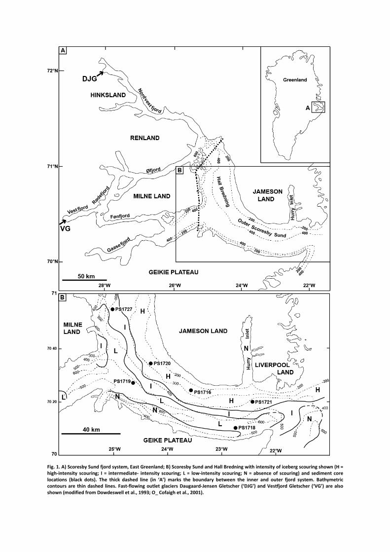
Fig. 1. A) Scoresby Sund fjord system, East Greenland; B) Scoresby Sund and Hall Bredning with intensity of iceberg scouring shown (H = high-intensity scouring; I = intermediate- intensity scouring; L = low-intensity scouring; N = absence of scouring) and sediment core locations (black dots). The thick dashed line (in ‘A’) marks the boundary between the inner and outer fjord system. Bathymetric contours are thin dashed lines. Fast-flowing outlet glaciers Daugaard-Jensen Gletscher (‘DJG’) and Vestfjord Gletscher (‘VG’) are also shown (modified from Dowdeswell et al., 1993; O_ Cofaigh et al., 2001).
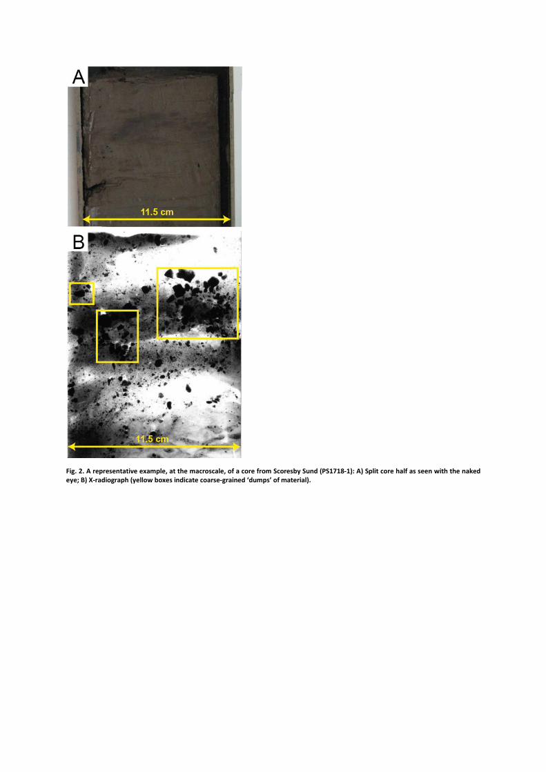
Fig. 2. A representative example, at the macroscale, of a core from Scoresby Sund (PS1718-1): A) Split core half as seen with the naked eye; B) X-radiograph (yellow boxes indicate coarse-grained ‘dumps’ of material).
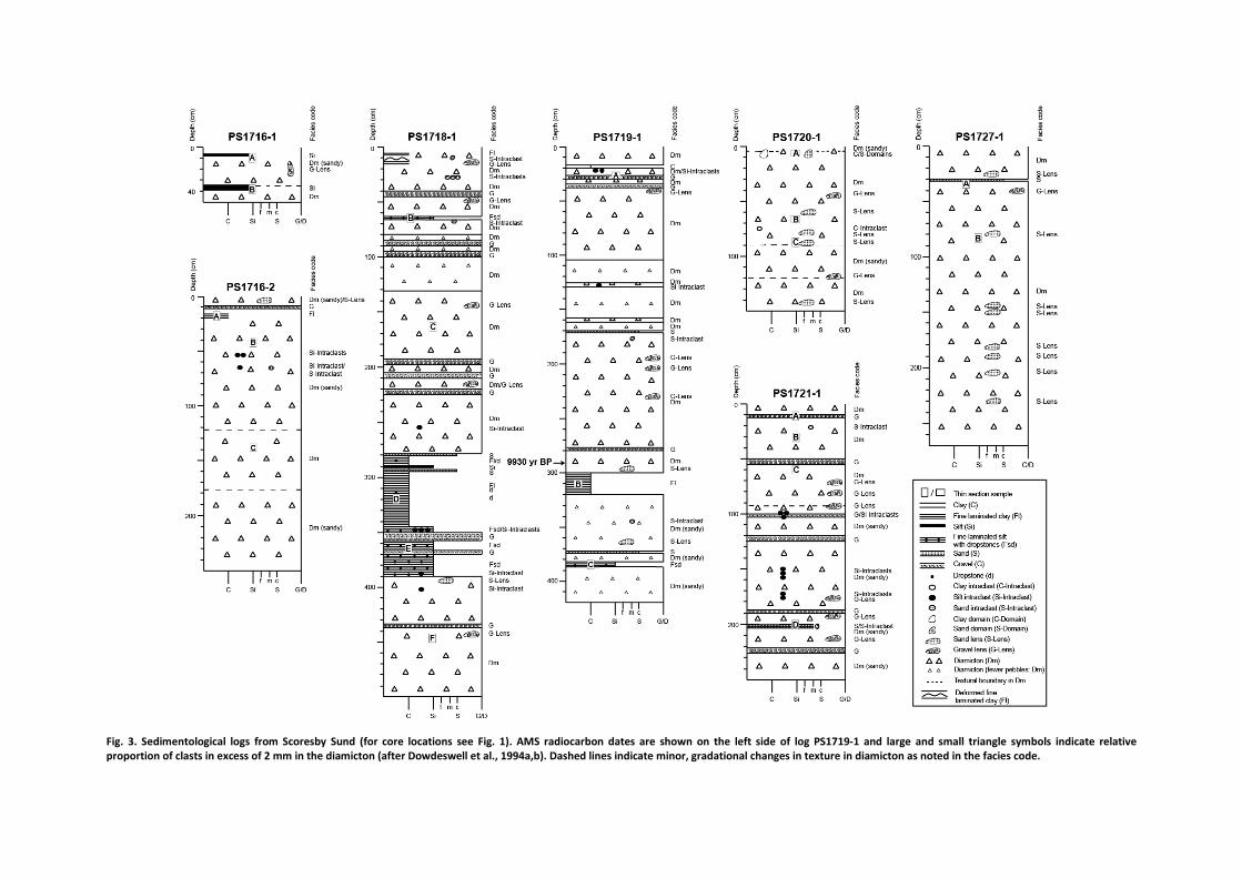
Fig. 3. Sedimentological logs from Scoresby Sund (for core locations see Fig. 1). AMS radiocarbon dates are shown on the left side of log PS1719-1 and large and small triangle symbols indicate relative proportion of clasts in excess of 2 mm in the diamicton (after Dowdeswell et al., 1994a,b). Dashed lines indicate minor, gradational changes in texture in diamicton as noted in the facies code.


Fig. 4. A representative selection of annotated full thin section scans: A) PS1721-1D, from a zone of high-intensity iceberg scouring (maximum width of sediment in the thin section is 36 mm); B) PS1727-1A, from a zone of intermediate-intensity iceberg scouring (maximum width of sediment in the thin section is 35 mm); C) PS1719-1A, from a zone of low-intensity iceberg scouring (maximum width of sediment in the thin section is 60 mm).
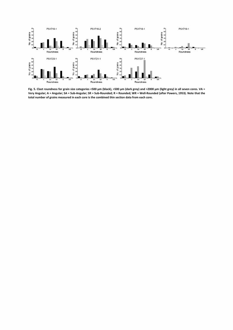
Fig. 5. Clast roundness for grain size categories <500 µm (black), >500 µm (dark grey) and >2000 µm (light grey) in all seven cores. VA = Very Angular; A = Angular; SA = Sub-Angular; SR = Sub-Rounded; R = Rounded; WR = Well-Rounded (after Powers, 1953). Note that the total number of grains measured in each core is the combined thin section data from each core.
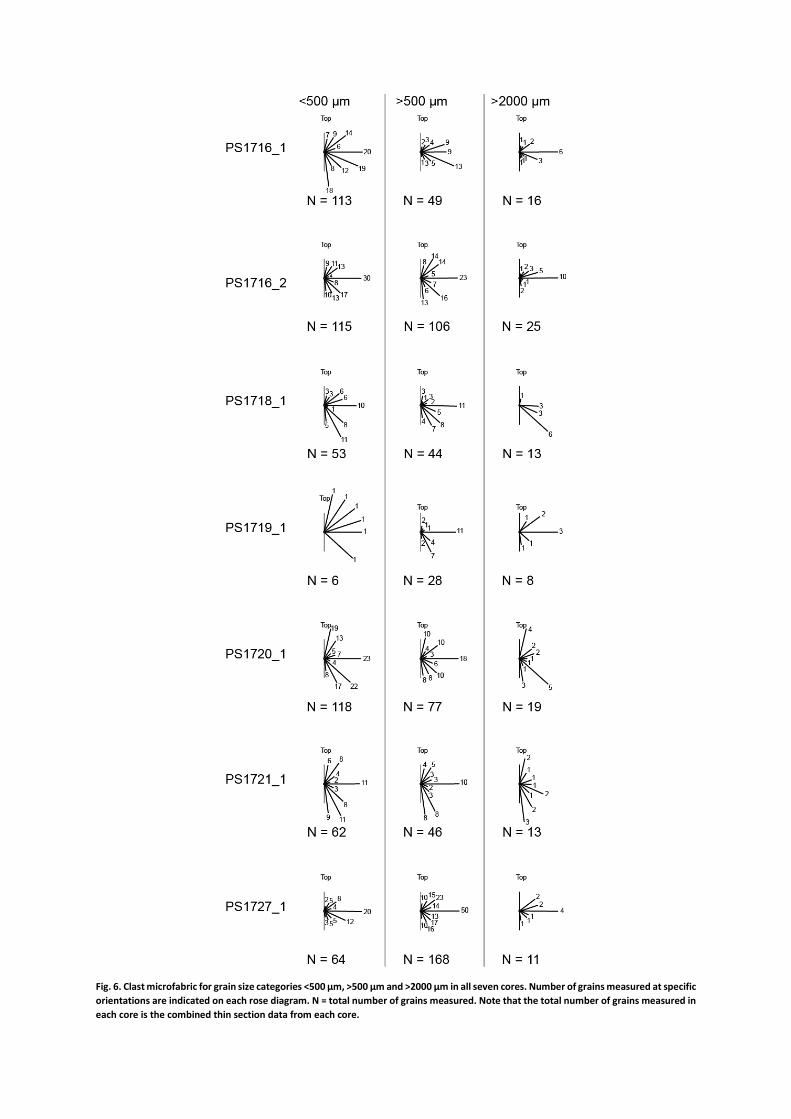
Fig. 6. Clast microfabric for grain size categories <500 µm, >500 µm and >2000 µm in all seven cores. Number of grains measured at specific orientations are indicated on each rose diagram. N = total number of grains measured. Note that the total number of grains measured in each core is the combined thin section data from each core.

Fig. 7. Microtextural elements in diamicton: A) matrix-rich diamict (PS1720-1C); B) clast-rich diamict (PS1720-1C); C) realigned crude bedding, alternating between fine- (indicated by the number ‘1’) and coarse- (indicated by the number ‘2’) grained material (PS1716-2B); D) realigned, crude coarse-grained bedding/banding sandwiched between two crude fine-grained laminations (PS1721-1D); E) fining upwards (PS1716-1A) – dashed line marks the approximate boundary between underlying coarser-grained material and overlying finer-grained material; grain turbate without a core stone is indicated inside the box; F) coarsening upwards (PS1716-2A) – dashed line marks the approximate boundary between underlying finer-grained material and overlying coarser-grained material.


Fig. 8. Microstructural deformation elements in diamicton. These are paired images where the second image in each pair is annotated in yellow. A) grain turbate with a core stone (PS1716-2C); B) grain turbate without a core stone (PS1716-1A); C) ‘swirled’ arrangement of grains (PS1721-1A); D) clast halo (left dashed line); rounded coarse domain (middle dashed line); and discrete, rounded fine-grained domain (right dashed line) (PS1716-2C); E) fine-grained deposits in clast embayments (PS1718-1F); F) folded sand layer (PS1720- 1C); G) sheath fold (PS1720-1C); H) realigned bedding of alternating coarse- and fine-grained material (PS1720-1A); I) augen-shape (tapered realigned bedding); laminated clays (to the left of the augen-shape); matrix lineations (within the augen-shape and to the right of it) (PS1720-1A); J) normal fault through a bed of birefringence (i.e. bedding-parallel plasmic fabric) (PS1727-1B); K) discrete shears (PS1716-1A); L) grain lineation (PS1720-1C); M) grain stack (big circle); green glauconite particle (small circle) (PS1716-1B); N) clay rafts (PS1719-1A); O) clast-rich intraclast type III (PS1716-1A); P) diamict intraclast type III (PS1721-1D); Q) sand intraclast type III (PS1720-1C); R) clayey intraclasts type III (dashed lines indicate intraclasts type III with diffuse boundaries) (PS1721-1A); S) clast-rich multiple domains adjacent to matrix-rich multiple domains (PS1727-1B); T) matrix-rich linear domains (PS1716-1B); U) realigned clasts and matrix, indicating a water escape structure (PS1721-1A); V) water escape structure filled with fines (i.e. a hyrdofracture) (PS1716-2C); W) skelsepic (dashed line) and unistrial (full lines) plasmic fabrics (PS1716-2A); X) skelsepic plasmic fabric band/halo (PS1719-1A); Y) unistrial plasmic fabric (PS1719- 1A); Z) unistrial plasmic fabric band (PS1718-1C).
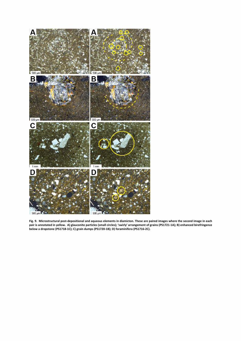
Fig. 9. Microstructural post-depositional and aqueous elements in diamicton. These are paired images where the second image in each pair is annotated in yellow. A) glauconite particles (small circles); ‘swirly’ arrangement of grains (PS1721-1A); B) enhanced birefringence below a dropstone (PS1718-1C); C) grain dumps (PS1720-1B); D) foraminifera (PS1716-2C).
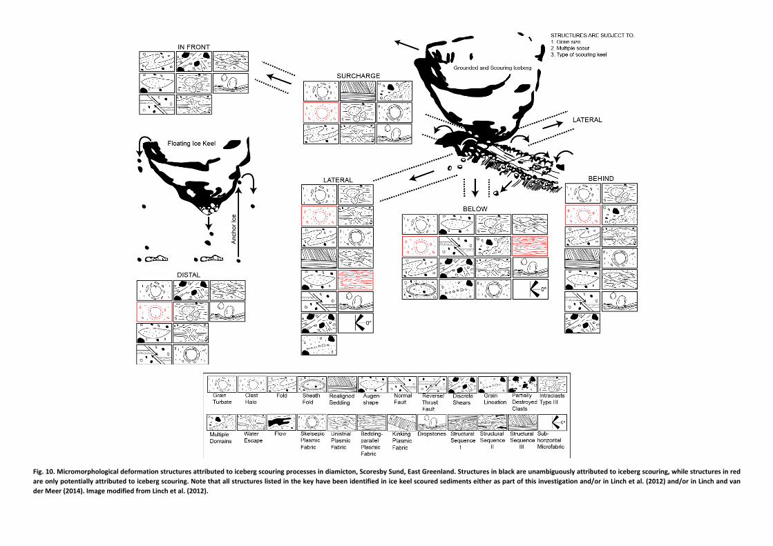
Fig. 10. Micromorphological deformation structures attributed to iceberg scouring processes in diamicton, Scoresby Sund, East Greenland. Structures in black are unambiguously attributed to iceberg scouring, while structures in red are only potentially attributed to iceberg scouring. Note that all structures listed in the key have been identified in ice keel scoured sediments either as part of this investigation and/or in Linch et al. (2012) and/or in Linch and van der Meer (2014). Image modified from Linch et al. (2012).

Table 1. Intensity of iceberg scouring in Hall Bredning and Scoresby Sund (Dowdeswell et al., 1993).
Scouring Intensity
Scouring of Seafloor
(%)
Water Depth (m)
Seafloor Characteristics
High-Intensity Scouring (HIS) 45 <300 - 400
• Seafloor reflection on Parasound records is poorly defined: highly irregular and discontinuous, underlying zone of diffuse signal return
• Scour crests appear sharp • Flat/undisturbed seafloor is absent • Found in a wide arc around the north and east coast of Hall
Bredning and Scoresby Sund
Intermediate-Intensity Scouring
(IIS) 21 300 - 500
• Seafloor reflection on Parasound records is strong: the diffuse appearance that is characteristic of high-intensity scouring is reduced
• Individual scours are rounded • Few flat/undisturbed seafloor areas • Found parallel to the distribution of HIS and in the mouth of
Scoresby Sund where water shallows from 600 m to <500 m
Low-Intensity Scouring
(LIS) 26 400 - >500
• Seafloor reflection on Parasound records is distinctly defined: zones of underlying diffuse signal decrease and disappear
• Isolated berm/trough features • Zones of flat/undisturbed seafloor • Found on the deeper, southern side of the central axis of the Sund
Absent 8 500 - >600
• Scours are absent • Planar surface reflection on Parasound records is underlain by well-
stratified sediments • Slopes with limited sediment cover or features indicative of mass
transfer • Hummocky to highly irregular bedrock-controlled surfaces • Most significant area is within 10 km of the southern coast of
Scoresby Sund
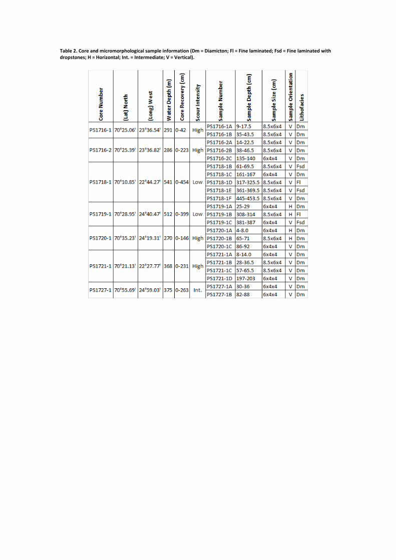
Table 2. Core and micromorphological sample information (Dm = Diamicton; Fl = Fine laminated; Fsd = Fine laminated with dropstones; H = Horizontal; Int. = Intermediate; V = Vertical).
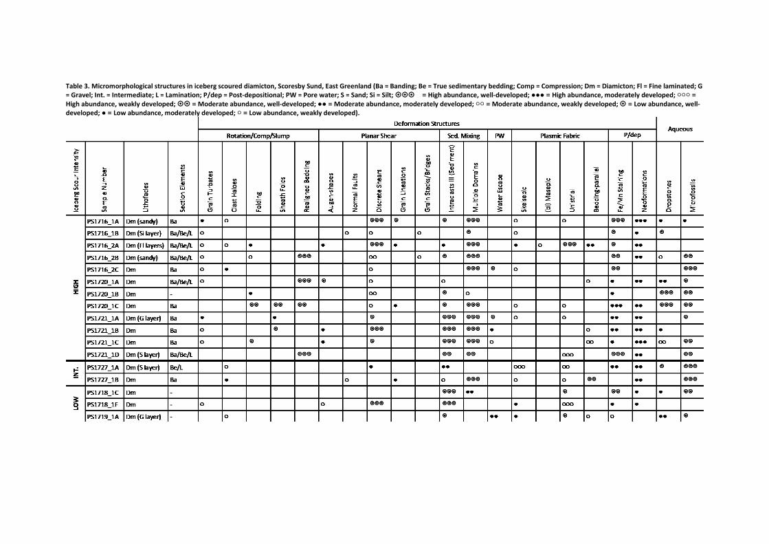
Table 3. Micromorphological structures in iceberg scoured diamicton, Scoresby Sund, East Greenland (Ba = Banding; Be = True sedimentary bedding; Comp = Compression; Dm = Diamicton; Fl = Fine laminated; G = Gravel; Int. = Intermediate; L = Lamination; P/dep = Post-depositional; PW = Pore water; S = Sand; Si = Silt; = High abundance, well-developed; ●●● = High abundance, moderately developed; ○○○ = High abundance, weakly developed; = Moderate abundance, well-developed; ●● = Moderate abundance, moderately developed; ○○ = Moderate abundance, weakly developed; = Low abundance, well-developed; ● = Low abundance, moderately developed; ○ = Low abundance, weakly developed).

Table 4. Particle size distribution and carbonate content of diamicton.
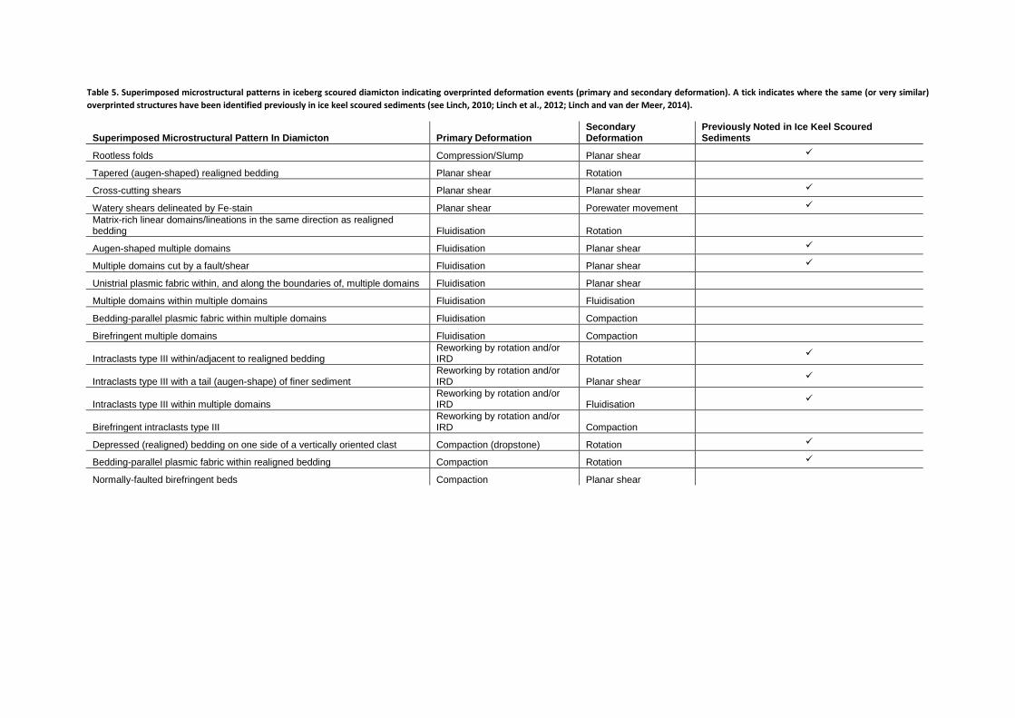
Table 5. Superimposed microstructural patterns in iceberg scoured diamicton indicating overprinted deformation events (primary and secondary deformation). A tick indicates where the same (or very similar) overprinted structures have been identified previously in ice keel scoured sediments (see Linch, 2010; Linch et al., 2012; Linch and van der Meer, 2014).
Superimposed Microstructural Pattern In Diamicton Primary Deformation Secondary Deformation
Previously Noted in Ice Keel Scoured Sediments
Rootless folds Compression/Slump Planar shear
Tapered (augen-shaped) realigned bedding Planar shear Rotation
Cross-cutting shears Planar shear Planar shear
Watery shears delineated by Fe-stain Planar shear Porewater movement
Matrix-rich linear domains/lineations in the same direction as realigned bedding Fluidisation Rotation
Augen-shaped multiple domains Fluidisation Planar shear
Multiple domains cut by a fault/shear Fluidisation Planar shear
Unistrial plasmic fabric within, and along the boundaries of, multiple domains Fluidisation Planar shear
Multiple domains within multiple domains Fluidisation Fluidisation
Bedding-parallel plasmic fabric within multiple domains Fluidisation Compaction
Birefringent multiple domains Fluidisation Compaction
Intraclasts type III within/adjacent to realigned bedding Reworking by rotation and/or IRD Rotation
Intraclasts type III with a tail (augen-shape) of finer sediment Reworking by rotation and/or IRD Planar shear
Intraclasts type III within multiple domains Reworking by rotation and/or IRD Fluidisation
Birefringent intraclasts type III Reworking by rotation and/or IRD Compaction
Depressed (realigned) bedding on one side of a vertically oriented clast Compaction (dropstone) Rotation
Bedding-parallel plasmic fabric within realigned bedding Compaction Rotation
Normally-faulted birefringent beds Compaction Planar shear
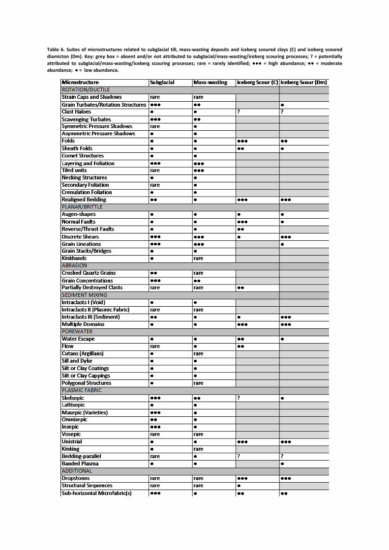
Table 6. Suites of microstructures related to subglacial till, mass-wasting deposits and iceberg scoured clays (C) and iceberg scoured diamicton (Dm). Key: grey box = absent and/or not attributed to subglacial/mass-wasting/iceberg scouring processes; ? = potentially attributed to subglacial/mass-wasting/iceberg scouring processes; rare = rarely identified; ●●● = high abundance; ●● = moderate abundance; ● = low abundance.