
Micro Data Center Customer Guide - Panduit · The Micro Data Center design addresses the need ......
10
Micro Data Center Customer Guide Figure 1: Suggested Equipment Layout
Transcript of Micro Data Center Customer Guide - Panduit · The Micro Data Center design addresses the need ......

Micro Data Center Customer Guide
Figure 1: Suggested Equipment Layout

Page 1

Page 2
Table of Contents Introduction ................................................................................................................................... 3
Equipment Layout ..................................................................................................................... 3
Network Cabling – Media Selection .......................................................................................... 4
Power and Grounding ............................................................................................................... 4
Power ..................................................................................................................................... 4
Grounding .............................................................................................................................. 5
Equipment Overview ..................................................................................................................... 5
Compute ................................................................................................................................ 5
Network .................................................................................................................................. 5
Storage .................................................................................................................................. 5
Physical Infrastructure Expansion ............................................................................................. 5
Converged Plantwide Ethernet and the Manufacturing Zone ....................................................... 6
Cabinet Elevation .......................................................................................................................... 7
Cabinet Preparation ...................................................................................................................... 8

Page 3
Introduction The Panduit Pre-Configured Micro Data Center (MDC) is a versatile framework that facilitates the rapid deployment of Information Technology (IT) or Operational Technology (OT) network capability that can be used in the small office as a complete datacenter in a single space, or in the industrial environment as stand-alone system that runs Manufacturing Execution System (MES) applications such as:
Scheduling, process and event monitoring, production tracking HMIs, real-time device control and security Asset management, alarms and event handling and simulation Process automation, process optimization and safety Quality control, databases and historians Secure links to enterprise resource planning (ERP) systems for reporting and analysis.
The Micro Data Center design addresses the need for a structured approach to implementing robust, integrated and secure networks in the industrial space. Adhering to Converged Plantwide Ethernet (CPwE) principles, the MDC design represents the basic requirements of the manufacturing environment including:
Cabinets Equipment Layout Network Cabling – Media Selection and Security Power and Grounding Cable Management.
The purpose of this Application Note is to provide a guide for equipment layout, cabling infrastructure, grounding/bonding and labeling for a variety of possible MDC configurations. It is not comprehensive in that every potential use is defined, but rather serves as a starting point and roadmap for the development of a stand-alone datacenter that can deliver a broad range of IT and OT capabilities.
Equipment Layout Equipment layout in a cabinet depends on the number, weight, and type of components as well as segregation. Common design practice locates enterprise network equipment at the top and industrial network equipment at the bottom, with the DMZ positioned in the middle of the housing. Typically, heavy components are located at the bottom of the cabinet with the patch field located at the top for best stability. In general, like equipment should be grouped, and space left between groupings for expansion, improved airflow, and cable management. Common practice, when combining servers and switches in the same cabinet, is to reverse the switches so that connectivity for all devices is positioned to the rear of the cabinet. This promotes ease of access and cable organization, and mitigates the risks of network interruptions resulting from cabling errors. Network designers may wish to combine DIN rail mounted appliances within the Micro Data Center cabinet. The MDC design if flexible enough to allow for components such as PLCs, manufacturing switches, power supplies, batteries, and other industrial devices to be mounted in
Page 4
a rack-mounted DIN rail panel. Often this can eliminate the need for separate enclosures while closely linking DIN rail mounted devices to the network.
Network Cabling – Media Selection Industrial Ethernet media can be fiber optic and/or copper cabling. To properly select the cable media for the application, several design criteria must be considered.
Distances between the MDC and the zone enclosure or manufacturing equipment Type of information transmitted, and acceptable latency Equipment connectivity Environmental conditions, e.g. electrical noise, vibration, temperature moisture, etc. Ease of installation and maintenance frequency.
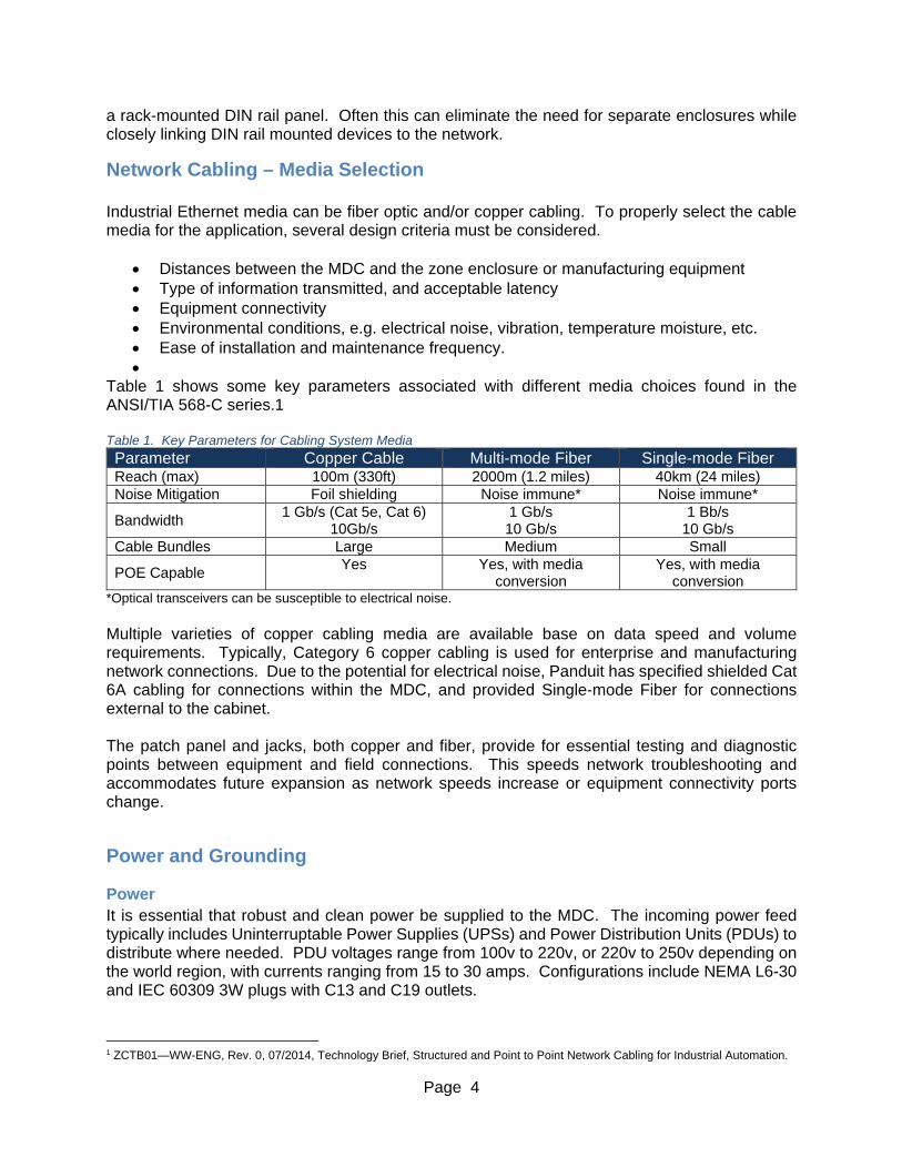
Table 1 shows some key parameters associated with different media choices found in the ANSI/TIA 568-C series.1 Table 1. Key Parameters for Cabling System Media
Parameter Copper Cable Multi-mode Fiber Single-mode Fiber Reach (max) 100m (330ft) 2000m (1.2 miles) 40km (24 miles) Noise Mitigation Foil shielding Noise immune* Noise immune*
Bandwidth 1 Gb/s (Cat 5e, Cat 6)
10Gb/s 1 Gb/s 10 Gb/s
1 Bb/s 10 Gb/s
Cable Bundles Large Medium Small
POE Capable Yes Yes, with media
conversion Yes, with media
conversion *Optical transceivers can be susceptible to electrical noise. Multiple varieties of copper cabling media are available base on data speed and volume requirements. Typically, Category 6 copper cabling is used for enterprise and manufacturing network connections. Due to the potential for electrical noise, Panduit has specified shielded Cat 6A cabling for connections within the MDC, and provided Single-mode Fiber for connections external to the cabinet. The patch panel and jacks, both copper and fiber, provide for essential testing and diagnostic points between equipment and field connections. This speeds network troubleshooting and accommodates future expansion as network speeds increase or equipment connectivity ports change.
Power and Grounding
Power It is essential that robust and clean power be supplied to the MDC. The incoming power feed typically includes Uninterruptable Power Supplies (UPSs) and Power Distribution Units (PDUs) to distribute where needed. PDU voltages range from 100v to 220v, or 220v to 250v depending on the world region, with currents ranging from 15 to 30 amps. Configurations include NEMA L6-30 and IEC 60309 3W plugs with C13 and C19 outlets.
1 ZCTB01—WW-ENG, Rev. 0, 07/2014, Technology Brief, Structured and Point to Point Network Cabling for Industrial Automation.

Page 5
Grounding Proper grounding of the MDC is critical to optimizing performance of all equipment located within the MDC. There are several methods used in the MDC to complete the bond between components, cabinet frame, and busbar – all the way to the building ground network. These methods include paint piercing screws and washers to ensure a direct metal-to-metal connection throughout the MDC, grounding jumpers to connect equipment to the cabinet structure, and braided ground to connect the cabinet to the Mesh Common Bonding Network (MCBN).
Equipment Overview The Panduit Micro Data Center design has been built around a proven minimum combination of server, storage and switches with free space left for server expansion, storage expansion, added functionality and/or DIN rail mounted switches and supporting devices. To ensure that the MDC is suitable for remote office locations and industrial applications Panduit recommends that network components are installed in a structured manner, and include compatible components, including the following:
Compute Cisco C240 M4 server(s).
Network Cisco 3850 switches.
o 48 Port o 24 Port
GLC-SX-MM - 1000BASE-SX SFP transceiver modules for MMF.
Storage EMC VNXe 3200 disk processor enclosure EMC VNXe 3200 disk array enclosure.
Physical Infrastructure Expansion STP28X**xx – Panduit 28 AWG Shielded Category 6A network cabling FXE10-10M*** – LC to LC multimode duplex patch cord, 1.6mm cable – 50/125µm Power Distribution Unit Options
o Q1L2B3J2M24AFA0 – SmartZone networked MSPO series vertical PDU (NEMA L6-30P)
o QIL2B1L2N24AFA0 – SmartZone networked MSPO series vertical PDU (IEC-60309-6H 2P+E)
o P1T2B1L2N08ATA0 – Monitored Per Outlet (MPO) vertical PDU (NEMA L6-30P)). CPPL24WBLY – 24 port patch panel with labels, front removable snap-in CFFPL4
faceplates. CJS6X88TGY - Mini-com TX6 10 GIG Shielded Jack Modules. CMDSLCZBU - Duplex LC Sr./Sr. Fiber Adapter With Module Zirconia ceramic split
sleeves. RGEJ1024URT - #10 AWG network grounding equipment jumper, 24" RGEJ660U, RGEJ696U - #6 AWG network grounding equipment jumper 60”, 96”. Fiber adapter panels – QuickNet Cassettes, FAP* adapter panels, or FOSM* splice
modules.

Page 6
Converged Plantwide Ethernet and the Manufacturing Zone In the design of the industrial Ethernet network, one of the critical elements is to ensure the separation between the enterprise network and the Manufacturing Zone. In terms of the Purdue Reference Model, this is the separation between Levels 0 to 3 and Levels 4 to 5. This separation is necessary because real-time availability and security are the critical elements for the traffic in the Industrial Automation Control System (IACS) network. This approach permits the Manufacturing Zone to function entirely on its own, irrespective of the connectivity status to the higher levels. As a best practice, it’s recommend that all manufacturing assets required for the operation of the Manufacturing zone should remain there. These assets include factory applications as well as services such as Active Directory, and DNS. Within the Manufacturing Zone, resides the IACS network and potentially, elements of the Cell and Area Zones. The Level 3 Site Operations layout includes virtual servers, security and network services, and a robust physical layer that addresses the environmental, performance, and security challenges present when deploying IT assets,(e.g., servers, storage arrays, and switching) in industrial settings. Figure 2: CPwE Zone Diagram

Page 7
Cabinet Elevation
Panduit’s Micro Data Center (MDC) provides the basic structure for the stand-alone data center in the remote office, as well as CPwE architecture that provides standard network services to the applications, devices, and equipment in modern IACS applications. The MDC provides design and implementation guidance to achieve the real-time communication and deterministic requirements of the IACS as well as the reliability and resiliency required by those systems.
Figure 3: Planning the Elevation in the 42 RU MDC
The 42 RU Micro Data Center is preconfigured for a minimum of one 2 RU server, one 2 RU storage device and two switches along with power accessories, along with a minimum of connectivity that supports the devices. Additional network equipment should be stacked in the cabinet according to the CPwE architecture defined in Figure 2 above.
41
36
31
26
21
16
11
6
1
42
40
39
38
37
35
34
33
32
30
29
28
27
25
24
23
22
20
19
18
17
15
14
13
12
10
9
8
7
5
4
3
2
41
36
31
26
21
16
11
6
1
42
40
39
38
37
35
34
33
32
30
29
28
27
25
24
23
22
20
19
18
17
15
14
13
12
10
9
8
7
5
4
3
2
41
36
31
26
21
16
11
6
1
42
40
39
38
37
35
34
33
32
30
29
28
27
25
24
23
22
20
19
18
17
15
14
13
12
10
9
8
7
5
4
3
2
41
36
31
26
21
16
11
6
1
42
40
39
38
37
35
34
33
32
30
29
28
27
25
24
23
22
20
19
18
17
15
14
13
12
10
9
8
7
5
4
3
2
1200W AC
1200W ACM
SS
PC
Ie 4
5
PC
Ie 5
PC
Ie 6
12
PC
Ie 1
PC
Ie 2
PC
Ie 3
1
2
PSUMLOM
4321
1200W AC
1200W ACM
SS
PC
Ie 4
5
PC
Ie 5
PC
Ie 6
12
PC
Ie 1
PC
Ie 2
PC
Ie 3
1
2
PSUMLOM
4321
!
IntelInsideXE ON
UCSC24 0 M4
Con
sole
UC
S-H
DD
30
0G
I2F
105
15
K S
AS
30
0 G
B
!
1 6 12 18 24
UC
S-H
DD
30
0G
I2F
105
15
K S
AS
30
0 G
B
!
UC
S-H
DD
30
0G
I2F
105
15
K S
AS
30
0 G
B
!
UC
S-H
DD
30
0G
I2F
105
15
K S
AS
30
0 G
B
!
UC
S-H
DD
30
0G
I2F
105
15
K S
AS
30
0 G
B
!
UC
S-H
DD
30
0G
I2F
105
15
K S
AS
30
0 G
B
!
UC
S-H
DD
30
0G
I2F
105
15
K S
AS
30
0 G
B
!
UC
S-H
DD
30
0G
I2F
105
15
K S
AS
30
0 G
B
!
UC
S-H
DD
30
0G
I2F
105
15
K S
AS
30
0 G
B
!
UC
S-H
DD
30
0G
I2F
105
15
K S
AS
30
0 G
B
!
UC
S-H
DD
30
0G
I2F
105
15
K S
AS
30
0 G
B
!
UC
S-H
DD
30
0G
I2F
105
15
K S
AS
30
0 G
B
!
UC
S-H
DD
30
0G
I2F
105
15
K S
AS
30
0 G
B
!
UC
S-H
DD
30
0G
I2F
105
15
K S
AS
30
0 G
B
!
UC
S-H
DD
30
0G
I2F
105
15
K S
AS
30
0 G
B
!
UC
S-H
DD
30
0G
I2F
105
15
K S
AS
30
0 G
B
!
UC
S-H
DD
30
0G
I2F
105
15
K S
AS
30
0 G
B
!
UC
S-H
DD
30
0G
I2F
105
15
K S
AS
30
0 G
B
!
UC
S-H
DD
30
0G
I2F
105
15
K S
AS
30
0 G
B
!
UC
S-H
DD
30
0G
I2F
105
15
K S
AS
30
0 G
B
!
UC
S-H
DD
30
0G
I2F
105
15
K S
AS
30
0 G
B
!
UC
S-H
DD
30
0G
I2F
105
15
K S
AS
30
0 G
B
!
UC
S-H
DD
30
0G
I2F
105
15
K S
AS
30
0 G
B
!
UC
S-H
DD
30
0G
I2F
105
15
K S
AS
30
0 G
B
!
!
IntelInsideXE ON
UCSC24 0 M4
Con
sole
UC
S-H
DD
30
0G
I2F
105
15
K S
AS
30
0 G
B
!
1 6 12 18 24
UC
S-H
DD
30
0G
I2F
105
15
K S
AS
30
0 G
B
!
UC
S-H
DD
30
0G
I2F
105
15
K S
AS
30
0 G
B
!
UC
S-H
DD
30
0G
I2F
105
15
K S
AS
30
0 G
B
!
UC
S-H
DD
30
0G
I2F
105
15
K S
AS
30
0 G
B
!
UC
S-H
DD
30
0G
I2F
105
15
K S
AS
30
0 G
B
!
UC
S-H
DD
30
0G
I2F
105
15
K S
AS
30
0 G
B
!
UC
S-H
DD
30
0G
I2F
105
15
K S
AS
30
0 G
B
!
UC
S-H
DD
30
0G
I2F
105
15
K S
AS
30
0 G
B
!
UC
S-H
DD
30
0G
I2F
105
15
K S
AS
30
0 G
B
!
UC
S-H
DD
30
0G
I2F
105
15
K S
AS
30
0 G
B
!
UC
S-H
DD
30
0G
I2F
105
15
K S
AS
30
0 G
B
!
UC
S-H
DD
30
0G
I2F
105
15
K S
AS
30
0 G
B
!
UC
S-H
DD
30
0G
I2F
105
15
K S
AS
30
0 G
B
!
UC
S-H
DD
30
0G
I2F
105
15
K S
AS
30
0 G
B
!
UC
S-H
DD
30
0G
I2F
105
15
K S
AS
30
0 G
B
!
UC
S-H
DD
30
0G
I2F
105
15
K S
AS
30
0 G
B
!
UC
S-H
DD
30
0G
I2F
105
15
K S
AS
30
0 G
B
!
UC
S-H
DD
30
0G
I2F
105
15
K S
AS
30
0 G
B
!
UC
S-H
DD
30
0G
I2F
105
15
K S
AS
30
0 G
B
!
UC
S-H
DD
30
0G
I2F
105
15
K S
AS
30
0 G
B
!
UC
S-H
DD
30
0G
I2F
105
15
K S
AS
30
0 G
B
!
UC
S-H
DD
30
0G
I2F
105
15
K S
AS
30
0 G
B
!
UC
S-H
DD
30
0G
I2F
105
15
K S
AS
30
0 G
B
!
Enterprise WAN Patch FieldFiberCopper
Enterprise FirewallEnterprist NTP ServerEnterprise Core SwitchPatching
LCD Monitor Drawer KVMNetBackupDisk ArraysDisk Processors
IDMZ FirewallsIZ Core SwitchIDMZ NTP Time Server
Distribution Switches to Level 2 DevicesIndustrial Zone Core SwitchesIndustrial Zone NTP ServerIndustrial Wireless LAN Controller
Level 3 Site Operation Serversft Servers
Application ServersHistorian ServersActive Directory Server
PowerUPSHorizontal PDUs
ENTERPRISE NETWORK ZONELevels 4-5
INDUSTRIAL DEMILITARIZED ZONE
IACS NETWORKLevel 3
CELL / AREA ZONELevels 0-2
Man
ufa
ctu
ring
Zo
neLe
vels
0-3

Page 8
Figure 4: Planning the Elevation in the 24 RU MDC
The 24 RU Micro Data Center is preconfigured for a minimum of one 2 RU server, one 2 RU storage device, two switches and power accessories, along with a minimum of connectivity that supports the devices. Additional network equipment should be stacked in the cabinet according to the CPwE architecture defined in Figure 3 above.
Cabinet Preparation Cabinet preparation includes unpacking, cage nut installation, cabling and cable management, system grounding hardware. Refer to Net-Access S-Type Server Cabinet instructions (V00029EG) supplied with the cabinet for instructions.
21
16
11
6
1
24
23
22
20
19
18
17
15
14
13
12
10
9
8
7
5
4
3
2
21
16
11
6
1
24
23
22
20
19
18
17
15
14
13
12
10
9
8
7
5
4
3
2
21
16
11
6
1
24
23
22
20
19
18
17
15
14
13
12
10
9
8
7
5
4
3
2
21
16
11
6
1
24
23
22
20
19
18
17
15
14
13
12
10
9
8
7
5
4
3
2
1200W AC
1200W ACM
SS
PC
Ie 4
5
PC
Ie 5
PC
Ie 6
12
PC
Ie 1
PC
Ie 2
PC
Ie 3
1
2
PSUMLOM
4321
!
IntelInsideXEON
UCSC240 M4
Co
nso
le
UC
S-H
DD
300G
I2F
105
15K
SA
S300 G
B
!
1 6 12 18 24
UC
S-H
DD
300G
I2F
105
15K
SA
S300 G
B
!
UC
S-H
DD
300G
I2F
105
15K
SA
S300 G
B
!
UC
S-H
DD
300G
I2F
105
15K
SA
S300 G
B
!
UC
S-H
DD
300G
I2F
105
15K
SA
S300 G
B
!
UC
S-H
DD
300G
I2F
105
15K
SA
S300 G
B
!
UC
S-H
DD
300G
I2F
105
15K
SA
S300 G
B
!
UC
S-H
DD
300G
I2F
105
15K
SA
S300 G
B
!
UC
S-H
DD
300G
I2F
105
15K
SA
S300 G
B
!
UC
S-H
DD
300G
I2F
105
15K
SA
S300 G
B
!
UC
S-H
DD
300G
I2F
105
15K
SA
S300 G
B
!
UC
S-H
DD
300G
I2F
105
15K
SA
S300 G
B
!
UC
S-H
DD
300G
I2F
105
15K
SA
S300 G
B
!
UC
S-H
DD
300G
I2F
105
15K
SA
S300 G
B
!
UC
S-H
DD
300G
I2F
105
15K
SA
S300 G
B
!
UC
S-H
DD
300G
I2F
105
15K
SA
S300 G
B
!
UC
S-H
DD
300G
I2F
105
15K
SA
S300 G
B
!
UC
S-H
DD
300G
I2F
105
15K
SA
S300 G
B
!
UC
S-H
DD
300G
I2F
105
15K
SA
S300 G
B
!
UC
S-H
DD
300G
I2F
105
15K
SA
S300 G
B
!
UC
S-H
DD
300G
I2F
105
15K
SA
S300 G
B
!
UC
S-H
DD
300G
I2F
105
15K
SA
S300 G
B
!
UC
S-H
DD
300G
I2F
105
15K
SA
S300 G
B
!
UC
S-H
DD
300G
I2F
105
15K
SA
S300 G
B
!
Enerprise WAN Patch Field
IDMZ Firewall
NetBackupDisk ArraysDisk Processors
Level 3 Site Operations ServersApplication ServersHistorian ServerActive Directory Server
PowerUPSHorizontal PDU
Industrial Zone Core Switches
1200W AC
1200W ACM
SS
PC
Ie 4
5
PC
Ie 5
PC
Ie 6
12
PC
Ie 1
PC
Ie 2
PC
Ie 3
1
2
PSUMLOM
4321
1200W AC
1200W ACM
SS
PC
Ie 4
5
PC
Ie 5
PC
Ie 6
12
PC
Ie 1
PC
Ie 2
PC
Ie 3
1
2
PSUMLOM
4321
ENTERPRISENETWORK ZONE
Levels 4-5
IACS NETWORKLevel 3
CELL / AREA ZONELevels 0-2
MA
NU
FA
CT
UR
ING
ZO
NE
Le
vel
s 0
-3
!
IntelInsideXEON
UCSC240 M4
Con
sole
UC
S-H
DD30
0GI2
F10
515K
SA
S300 G
B
!
1 6 12 18 24
UC
S-H
DD30
0GI2
F10
515K
SA
S300 G
B
!
UC
S-H
DD30
0GI2
F10
515K
SA
S300 G
B
!
UC
S-H
DD30
0GI2
F10
515K
SA
S300 G
B
!
UC
S-H
DD30
0GI2
F10
515K
SA
S300 G
B
!
UC
S-H
DD30
0GI2
F10
515K
SA
S300 G
B
!
UC
S-H
DD30
0GI2
F10
515K
SA
S300 G
B
!
UC
S-H
DD30
0GI2
F10
515K
SA
S300 G
B
!
UC
S-H
DD30
0GI2
F10
515K
SA
S300 G
B
!
UC
S-H
DD30
0GI2
F10
515K
SA
S300 G
B
!
UC
S-H
DD30
0GI2
F10
515K
SA
S300 G
B
!
UC
S-H
DD30
0GI2
F10
515K
SA
S300 G
B
!
UC
S-H
DD30
0GI2
F10
515K
SA
S300 G
B
!
UC
S-H
DD30
0GI2
F10
515K
SA
S300 G
B
!
UC
S-H
DD30
0GI2
F10
515K
SA
S300 G
B
!
UC
S-H
DD30
0GI2
F10
515K
SA
S300 G
B
!
UC
S-H
DD30
0GI2
F10
515K
SA
S300 G
B
!
UC
S-H
DD30
0GI2
F10
515K
SA
S300 G
B
!
UC
S-H
DD30
0GI2
F10
515K
SA
S300 G
B
!
UC
S-H
DD30
0GI2
F10
515K
SA
S300 G
B
!
UC
S-H
DD30
0GI2
F10
515K
SA
S300 G
B
!
UC
S-H
DD30
0GI2
F10
515K
SA
S300 G
B
!
UC
S-H
DD30
0GI2
F10
515K
SA
S300 G
B
!
UC
S-H
DD30
0GI2
F10
515K
SA
S300 G
B
!
!
IntelInsideXEON
UCSC240 M4
Con
sole
UC
S-H
DD30
0GI2
F10
515K
SA
S300 G
B
!
1 6 12 18 24
UC
S-H
DD30
0GI2
F10
515K
SA
S300 G
B
!
UC
S-H
DD30
0GI2
F10
515K
SA
S300 G
B
!
UC
S-H
DD30
0GI2
F10
515K
SA
S300 G
B
!
UC
S-H
DD30
0GI2
F10
515K
SA
S300 G
B
!
UC
S-H
DD30
0GI2
F10
515K
SA
S300 G
B
!
UC
S-H
DD30
0GI2
F10
515K
SA
S300 G
B
!
UC
S-H
DD30
0GI2
F10
515K
SA
S300 G
B
!
UC
S-H
DD30
0GI2
F10
515K
SA
S300 G
B
!
UC
S-H
DD30
0GI2
F10
515K
SA
S300 G
B
!
UC
S-H
DD30
0GI2
F10
515K
SA
S300 G
B
!
UC
S-H
DD30
0GI2
F10
515K
SA
S300 G
B
!
UC
S-H
DD30
0GI2
F10
515K
SA
S300 G
B
!
UC
S-H
DD30
0GI2
F10
515K
SA
S300 G
B
!
UC
S-H
DD30
0GI2
F10
515K
SA
S300 G
B
!
UC
S-H
DD30
0GI2
F10
515K
SA
S300 G
B
!
UC
S-H
DD30
0GI2
F10
515K
SA
S300 G
B
!
UC
S-H
DD30
0GI2
F10
515K
SA
S300 G
B
!
UC
S-H
DD30
0GI2
F10
515K
SA
S300 G
B
!
UC
S-H
DD30
0GI2
F10
515K
SA
S300 G
B
!
UC
S-H
DD30
0GI2
F10
515K
SA
S300 G
B
!
UC
S-H
DD30
0GI2
F10
515K
SA
S300 G
B
!
UC
S-H
DD30
0GI2
F10
515K
SA
S300 G
B
!
UC
S-H
DD30
0GI2
F10
515K
SA
S300 G
B
!

Page 9
IA-CD-0003-Customer Guide – Micro Data Center Rev00A - 2016