MICE RF and Coupling Coil Module Integration Issues Steve Virostek Lawrence Berkeley National...
9
MICE RF and Coupling Coil Module Integration Issues Steve Virostek Lawrence Berkeley National Laboratory MICE Collaboration Meeting October 27, 2004
-
date post
19-Dec-2015 -
Category
Documents
-
view
227 -
download
0
Transcript of MICE RF and Coupling Coil Module Integration Issues Steve Virostek Lawrence Berkeley National...
MICE RF and Coupling Coil
Module Integration Issues
Steve VirostekLawrence Berkeley National Laboratory
MICE Collaboration Meeting October 27, 2004

RF/CC Module Integration
Steve Virostek - LBNL Page 2
Module Integration Topics
•Module-to-module joint•Conceptual design
•Configuration
•Load and stress analysis
•Module support structure•Conceptual design
•Structural analysis
•Modal and seismic analysis
•Interface with experimental hall (rails)
RF/CC Module Integration
Steve Virostek - LBNL Page 3
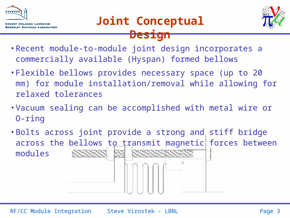
Joint Conceptual Design
•Recent module-to-module joint design incorporates a commercially available (Hyspan) formed bellows
•Flexible bellows provides necessary space (up to 20 mm) for module installation/removal while allowing for relaxed tolerances
•Vacuum sealing can be accomplished with metal wire or O-ring
•Bolts across joint provide a strong and stiff bridge across the bellows to transmit magnetic forces between modules
RF/CC Module Integration
Steve Virostek - LBNL Page 4
Joint Configuration
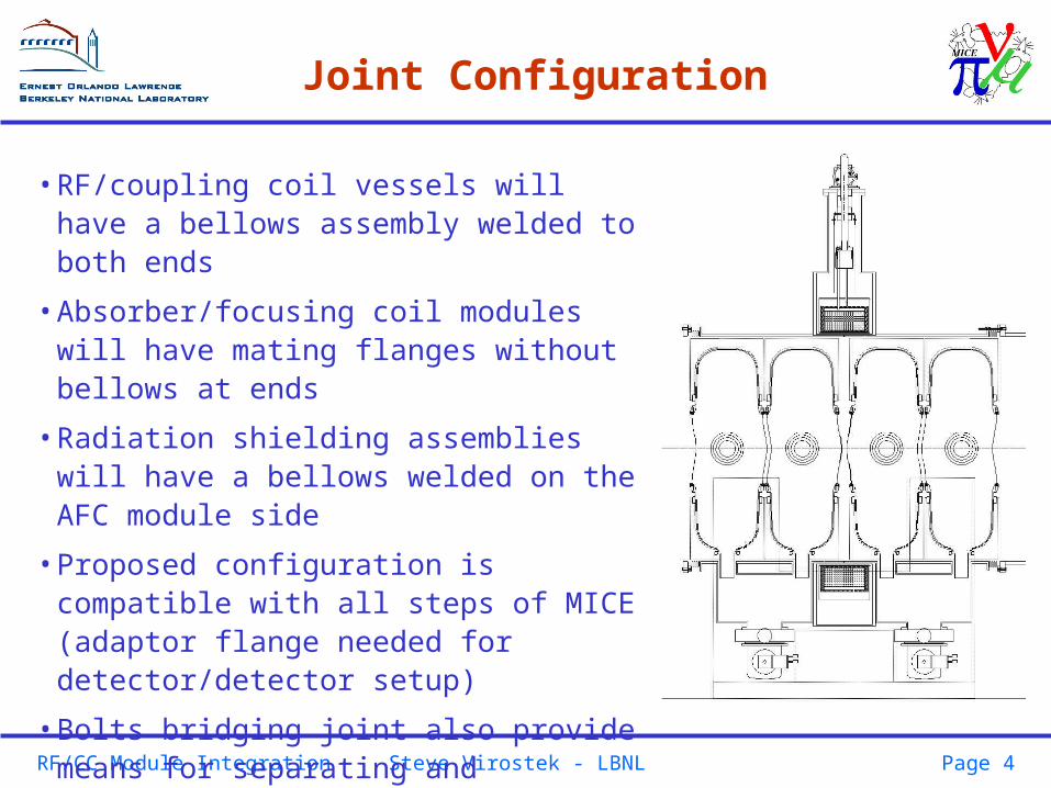
•RF/coupling coil vessels will have a bellows assembly welded to both ends
•Absorber/focusing coil modules will have mating flanges without bellows at ends
•Radiation shielding assemblies will have a bellows welded on the AFC module side
•Proposed configuration is compatible with all steps of MICE (adaptor flange needed for detector/detector setup)
•Bolts bridging joint also provide means for separating and maintaining gap between flanges during installation and removal

RF/CC Module Integration
Steve Virostek - LBNL Page 5
Joint Load and Stress Analysis
•Magnetic forces are intended to be transmitted between the AFC and RF/CC modules through the vessel shells and across the bellows through the joint bridging bolts
•Loads will not be carried across AFC/detector joints
•Total number of bolts required around circumference of joint to be based on sealing requirements
•Not all of the sealing bolts will bridge the joint – quantity will be determined from the load and stress analysis
•Flange and weld sizes will result from a future detailed stress analysis of the module vacuum vessels

RF/CC Module Integration
Steve Virostek - LBNL Page 6
Support Conceptual Design
RF/CC Module Integration
Steve Virostek - LBNL Page 7
Support Conceptual Design
•Support concept incorporates thick side plates welded directly to the RF/CC module vessel
•Side plates provide for high strength and stiffness in the axial direction to carry magnet loads to the floor
•Cross supports provide lateral stability and stiffness
•Side plate cutouts provide clearance for coupling coil and access to vacuum system and cavity tuners
•Support is permanently joined to the vacuum vessel during fabrication and prior to module assembly

RF/CC Module Integration
Steve Virostek - LBNL Page 8
Support Structural Analysis
•Module support structural analysis yet to be completed
•Material and weld stress calculations will be based on magnetic, vacuum, gravity and seismic loading conditions
•Support design expected to be dominated by the need to withstand and restrain magnetic forces
•Modal finite element analysis will be used to determine natural frequency of vibration and mode shapes for support system and subcomponents
•A design goal of 10 to 20 Hz natural frequency should be adequate to satisfy physics requirements and will result in minimal acceleration magnification during seismic activity
RF/CC Module Integration
Steve Virostek - LBNL Page 9
Support Interface with System
•RF/CC module likely to be mounted on a rail system oriented transversely to the beamline
•Support stand height recently reduced to 1524 mm (beamline to base) to allow for 160 mm rail height
•Reduced height has minimal impact on system
•Interface points between module support base and rails yet to be determined