MG Hydraulic Kit ISARMATIC - Western...
48
U\ & ~ (M êI IT 0 ~ ~ ~ ~ (i OcQ& ;.f J L ~__ ---- Lit. No. 62880 6/03/04
Transcript of MG Hydraulic Kit ISARMATIC - Western...
U\ & ~ (M êI IT 0 ~ ~ ~
~ (i OcQ&
;.fJL ~__ ----
Lit. No. 628806/03/04

Western Products
P.O. Box 245038Milwaukee, Wisconsin 53224-9538
Division of Douglas Dynamics, Inc.
Western reserves the right under its product improvement proceduresto change construction or design details and furnish equipment whenso altered without reference to ilustrations or specifications usedherein. The following are registered(ß and unregestered™ Trade Marksof Douglas Dynamics, Inc.:
WESTERN(B
ISARMATIC(ß
Hydra- Turn(ß
RolI-Action(ß
UniMount(ß
Western and the vehicle manufacturer may require and/or recom-mend optional equipment for snow removaL. See Western's installa-tion instructions for details. Western offers a one-year limited warrantyfor all snowplows and accessories. See separately printed page forthis important information.

TABLE OF CONTENTS
ISARMATIC(B Mark Ilia. Cable
1 · Safety RulesBefore You Begin . . . . . . . . . . . . . . . . . . . . . . . . . . . . . . . . . . . . . . . .Personal Safety
VentilationFire and Explosion . . . . . . . . . . . . . . . . . . . . . . . . . . . . . . . . . . . . . . .Battery Safety ..........................................
Hydraulic Safety
.... ....................... ...... ............... .... ..................................
....... ............... ..................2 · Plow Tune-Up and Inspection
Pre-service Preparation
Blade
A-Frame and Quadrant
Lift Mount . . . . . . . . . . . . . . . . . . . . . . . . . . . . . . . . . . . . . . . . . . . . . .HydraulicsElectricalSnowplow Accessories
....... ............................ ......... ............ .......... .................
................................. ..
............................................ ........ ............... ........................
.................................. .
3 · Description of Major ComponentsC:ollponents . . . . . . . . . . . . . . . . . . . . . . . . . . . . . . . . . . . . . . . . . . . .Theory of Operation . . . . . . . . . . . . . . . . . . . . . . . . . . . . . . . . . . . . . .
.1-1
.1-1
.1-1
.1-1
.1-1
.1-2
.2-1
.2-1
.2-2
.2-3
.2-4
.2-6
.2-7
.3-1
.3-4
ISARMATIC(B Mark Ilia · Cable.
4 · Troubleshooting Section
Troubleshooting Guide
Hydraulic Unit - Part Reference ....................
.... ...... .... ... ....... .......
. . .A. PUllp Pressure Test ...........................
B. Relay Test ............ .............. .....c:. C:ushion Valve AdjustllentD. 3-Way Valve Lever Travel ..........
E. 4-Way (Angle) Valve Lever Travel and Adjustllent ...
F. 3-Way (Raise/Lower) Valve Adjustllent ........
...... . .
. . . . . . ................
. . .F1. Lift Valve Adjustllent .........................
F2. C:heck Valve Adjustllent . . . . ....... ...... .... ......
5 · Breakdown and Reassembly
. . .
. . .4-1
. . . 4-2
. . . 4-2
. . . 4-3
. . . 4-4
. . . 4-5
. . .4-5
. . . 4-6
. . . 4-7
. . .4-7
. . .
Repair. . . . . . . . ... ...............................Warranty Repair . . . .Reference Guide With Photos
. . . . ......... ......... . ..... ..... ............
. . .5-1
. . .5-1
. . . 5-2
ii
SAFETY RULES
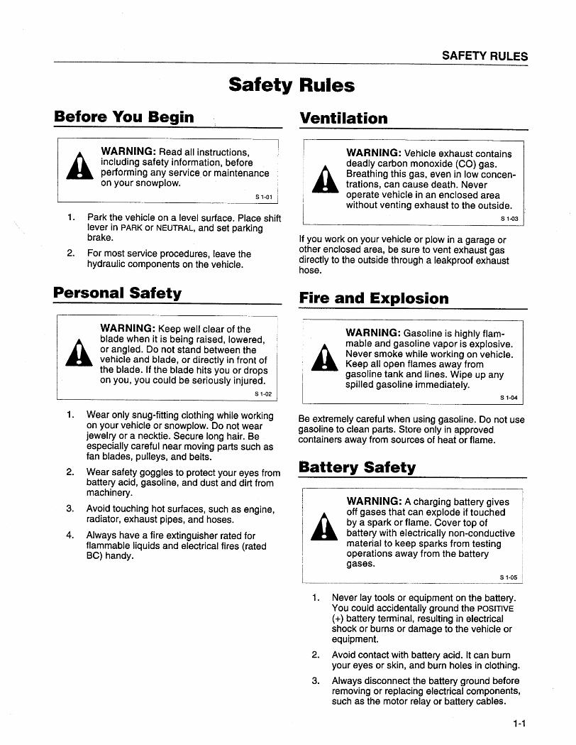
Safety RulesBefore You Begin
AWARNING: Read all instructions,including safety information, beforeperforming any service, or maintenanceon your snowplow.
S 1-01
1. Park the vehicle on a level surface. Place shift
lever in PARK or NEUTRAL, and set parkingbrake.
2. For most service procedures, leave the
hydraulic components on the vehicle.
Personal Safety
AWARNING: Keep well clear of theblade when it is being raised, lowered,or angled. Do not stand between thevehicle and blade, or directly in front ofthe blade. If the blade hits you or dropson you, you could be seriously injured.
S 1-02
1. Wear only snug-fitting clothing while workingon your vehicle or snowplow. Do not wearjewelry or a necktie. Secure long hair. Beespecially careful near moving parts such asfan blades, pulleys, and belts.
2. Wear safety goggles to protect your eyes frombattery acid, gasoline, and dust and dirt frommachinery .
3. Avoid touching hot surfaces, such as engine,
radiator, exhaust pipes, and hoses.
4. Always have a fire extinguisher rated forflammable liquids and electrical fires (ratedBC) handy.
Ventilation
AWARNING: Vehicle exhaust containsdeadly carbon monoxide (CO) gas.Breathing this gas, even in low concen-trations, can cause death. Neveroperate vehicle in an enclosed areawithout venting exhaust to the outside.
S 1-03
If you work on your vehicle or plow in a garage orother enclosed area, be sure to vent exhaust gasdirectly to the outside through a leakproof exhausthose.
Fire and Explosion
AWARNING: Gasoline is highly flam-mable and gasoline vapor is explosive.Never smoke while working on vehicle.Keep all open flames away fromgasoline tank and lines. Wipe up anyspilled gasoline immediately.
S 1-04
Be extremely careful when using gasoline. Do not usegasoline to clean parts. Store only in approvedcontainers away from sources of heat or flame.
Battery Safetyr-I!i
IAi
i~
WARNING: A charging battery givesoff gases that can explode if touchedby a spark or flame. Cover top ofbattery with electrically non-conductivematerial to keep sparks from testingoperations away from the batterygases.
!iiI-- -------~
1. Never lay tools or equipment on the battery.
You could accidentally ground the POSITIVE
(+) battery terminal, resulting in electricalshock or burns or damage to the vehicle orequipment.
2. Avoid contact with battery acid. It can burnyour eyes or skin, and burn holes in clothing.
3. Always disconnect the battery ground before
removing or replacing electrical components,such as the motor relay or battery cables.
1-1
ISARMATIC(B Mark Ilia · Cable
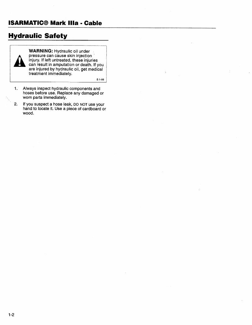
Hydraulic Safety
AWARNING: Hydraulic oil underpressure can cause skin injectioninjury. If left untreated, these injuriescan result in amputation or death. If youare injured by hydraulic oil, get medicaltreatment immediately.
S 1-06
1. Always inspect hydraulic components and
hoses before use. Replace any damaged orworn parts immediately.
2. If you suspect a hose leak, DO NOT use your
hand to locate it. Use a piece of cardboard orwood.
1-2
PLOW TUNE-UP AND INSPECTION
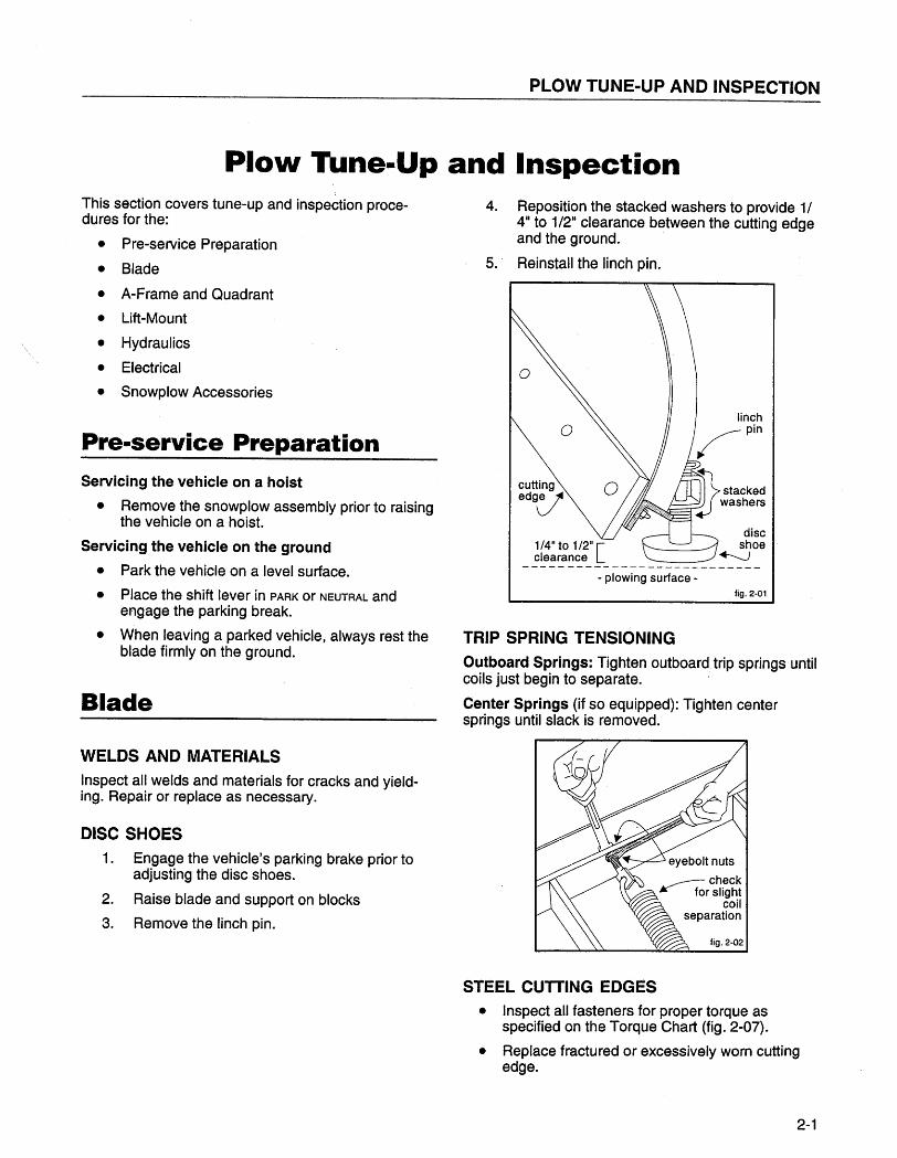
PIO\N Tune-Up and Inspection
This section covers tune-up and inspection proce-dures for the:
. Pre-service Preparation
. Blade
. A-Frame and Quadrant
. Lift-Mount
. Hydraulics
. Electrical
. Snowplow Accessories
Pre-service PreparationServicing the vehicle on a hoist
· Remove the snowplow assembly prior to raisingthe vehicle on a hoist.
Servicing the vehicle on the ground
. Park the vehicle on a level surface.
· Place the shift lever in PARK or NEUTRAL and
engage the parking break.
· When leaving a parked vehicle, always rest theblade firmly on the ground.
Blade
WELDS AND MATERIALS
Inspect all welds and materials for cracks and yield-ing. Repair or replace as necessary.
DISC SHOES1. Engage the vehicle's parking brake prior to
adjusting the disc shoes.
2. Raise blade and support on blocks
3. Remove the linch pin.
4. Reposition the stacked washers to provide 1/
411 to 1/211 clearance between the cutting edgeand the ground.
5.' Reinstall the linch pin.
1/4" to 1/2" íclearance L- -- -- ----- - - ---- -- -- -- -- ---
- plowing surface -fig. 2-01
TRIP SPRING TENSIONING
Outboard Springs: Tighten outboard trip springs untilcoils just begin to separate.
Center Springs (if so equipped): Tighten centersprings until slack is removed.
STEEL CUTTING EDGES. Inspect all fasteners for proper torque as
specified on the Torque Chart (fig. 2-07).
. Replace fractured or excessively worn cutting
edge.
2-1
ISARMATIC(8 Mark Ilia · Cable
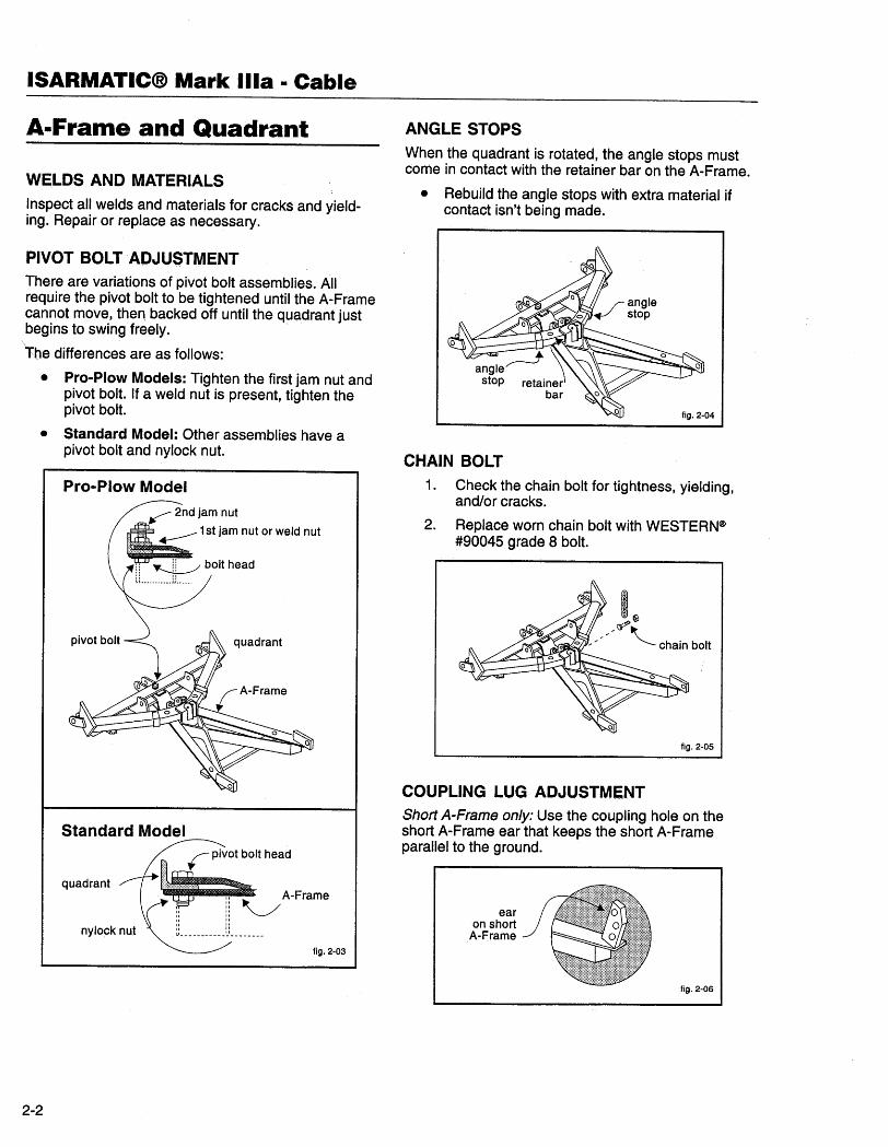
A-Frame and Quadrant
WELDS AND MATERIALS
Inspect all welds and materials for cracks and yield-ing. Repair or replace as necessary.
PIVOT BOLT ADJUSTMENTThere are variations of pivot bolt assemblies. Allrequire the pivot bolt to be tightened until the A-Framecannot move, then backed off until the quadrant justbegins to swing freely.
roe differences are as follows:
· Pro-Plow Models: Tighten the first jam nut andpivot bolt. If a weld nut is present, tighten thepivot bolt.
· Standard Model: Other assemblies have apivot bolt and nylock nut.
Pro-Plow Model
Standard Model
quadrant
nyloçk nut
fig. 2-03
2-2
ANGLE STOPS
When the quadrant is rotated, the angle stops mustcome in contact with the retainer bar on the A-Frame.
· Rebuild the angle stops with extra material ifcontact isn't being made.
CHAIN BOLT
1. Check the chain bolt for tightness, yielding,and/or cracks.
2. Replace worn chain bolt with WESTERN~#90045 grade 8 bolt.
~ ~i:~ chain bolt
fig. 2-05
COUPLING LUG ADJUSTMENTShort A-Frame only: Use the coupling hole on theshort A-Frame ear that keeps the short A-Frameparallel to the ground.
earon short
A-Frame
fig. 2-06
PLOW TUNE-UP AND INSPECTION
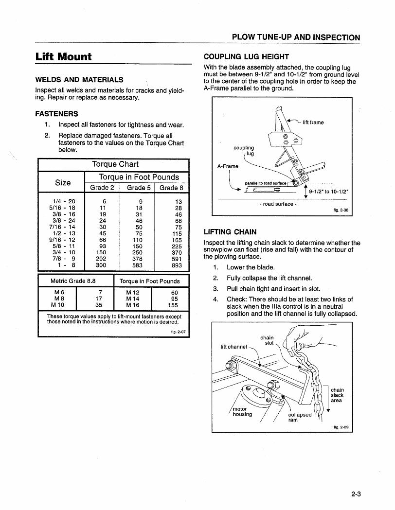
Lift Mount
WELDS AND MATERIALS
Inspect all welds and materials for cracks and yield-ing. Repair or replace as necessary.
FASTENERS1. Inspect all fasteners for tightness and wear.
2. Replace damaged fasteners. Torque allfasteners to the values on the Torque Chartbelow.
Torque Chart
SizeTorque in Foot Pounds
Grade 2 Grade 5 Grade 8
1/4 - 20 6 9 135/16 - 18 11 18 283/8 - 1 6 19 31 463/8 - 24 24 46 68
7/16 - 14 30 50 751 /2 - 1 3 45 75 115
9/16 - 12 66 110 1655/8 - 11 93 150 2253/4 - 10 150 250 3707/8 - 9 202 378 591
1 - 8 300 583 893
Metric Grade 8.8 Torque in Foot Pounds
M6 7 M 12 60M8 17 ,M 14 95
M 10 35 M 16 155
These torque values apply to lift-mount fasteners exceptthose noted in the instructions where motion is desired.
fig, 2-07
COUPLING LUG HEIGHT
With the blade assembly attached, the coupling lugmust be between 9-1/2" and 10-1/2" from ground levelto the center of the coupling hole in order to keep theA-Frame parallel to the ground.
A-Frame
L- road surface -
fig. 2-08
LIFTING CHAINInspect the lifting chain slack to determine whether thesnowplow can float (rise and fall) with the contour ofthe plowing surface.
1 . Lower the blade.
2. Fully collapse the lift channeL.
3. Pull chain tight and insert in slot.
4. Check: There should be at least two links ofslack when the ilia control is in a neutralposition and the lift channel is fully collapsed.
fig. 2-09
2-3
ISARMATIC(B Mark Ilia · Cable
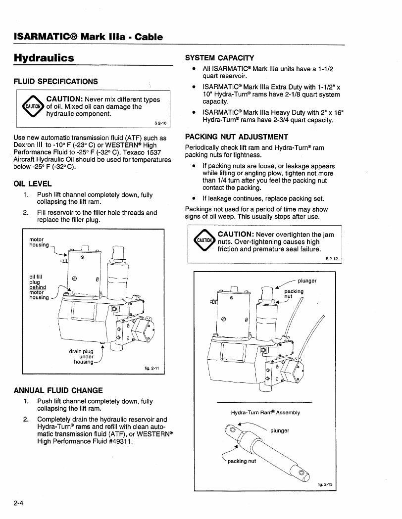
Hydraulics
FLUID SPECIFICATIONS
~ CAUTION: Never mix different typesCAUTION of oiL. Mixed oil can damage the
hydraulic component.S 2.10
Use new automatic transmission fluid (A TF) such asDexron III to -100 F (-230 C) or WESTERN(ß HighPerformance Fluid to -250 F (-320 C). Texaco 1537
. Aircraft Hydraulic Oil should be used for temperaturesbelow -250 F (-320 C).
OIL LEVEL1. Push lift channel completely down, fully
collapsing the lift ram.
2. Fill reservoir to the filler hole threads and
replace the filler plug.
oil filplugbehindmotorhousing
fig. 2-11
ANNUAL FLUID CHANGE
1. Push lift channel completely down, fullycollapsing the lift ram.
2. Completely drain the hydraulic reservoir andHydra- Turn(ß rams and refil with clean auto-matic transmission fluid (ATF), or WESTERN(ßHigh Performance Fluid #49311.
2-4
SYSTEM CAPACITY. AIIISARMATIC(ß Mark Ilia units have a 1-1/2
quart reservoir.
. ISARMATIC(ß Mark ilIa Extra Duty with 1-1/211 x10" Hydra-Turn(ß rams have 2-1/8 quart systemcapacity.
. ISARMATIC(ß Mark ilia Heavy Duty with 2" x 1611Hydra-Turn(ß rams have 2-3/4 quart capacity.
PACKING NUT ADJUSTMENTPeriodically check lift ram and Hydra- Turn(ß rampacking nuts for tightness.
. If packing nuts are loose, or leakage appears
while lifting or angling plow, tighten not morethan 1/4 turn after you feel the packing nutcontact the packing.
. If leakage continues, replace packing set.
Packings not used for a period of time may showsigns of oil weep. This usually stops after use.
e CAUTION: Never overtighten the jamCAUTIOK nuts. Over-tightening causes .high
friction and premature seal failure.S 2-12
Hydra-Turn Ram(! Assembly
fig. 2-13
PLOW TUNE-UP AND INSPECTION
LIFT AND ANGLE PLUNGERS1. When not in use, push lift channel all the way
down to protect the lift plunger from rustingand pitting.
2. During storage, grease all exposed chrome
surfaces on the angle plungers to preventcorrosion.
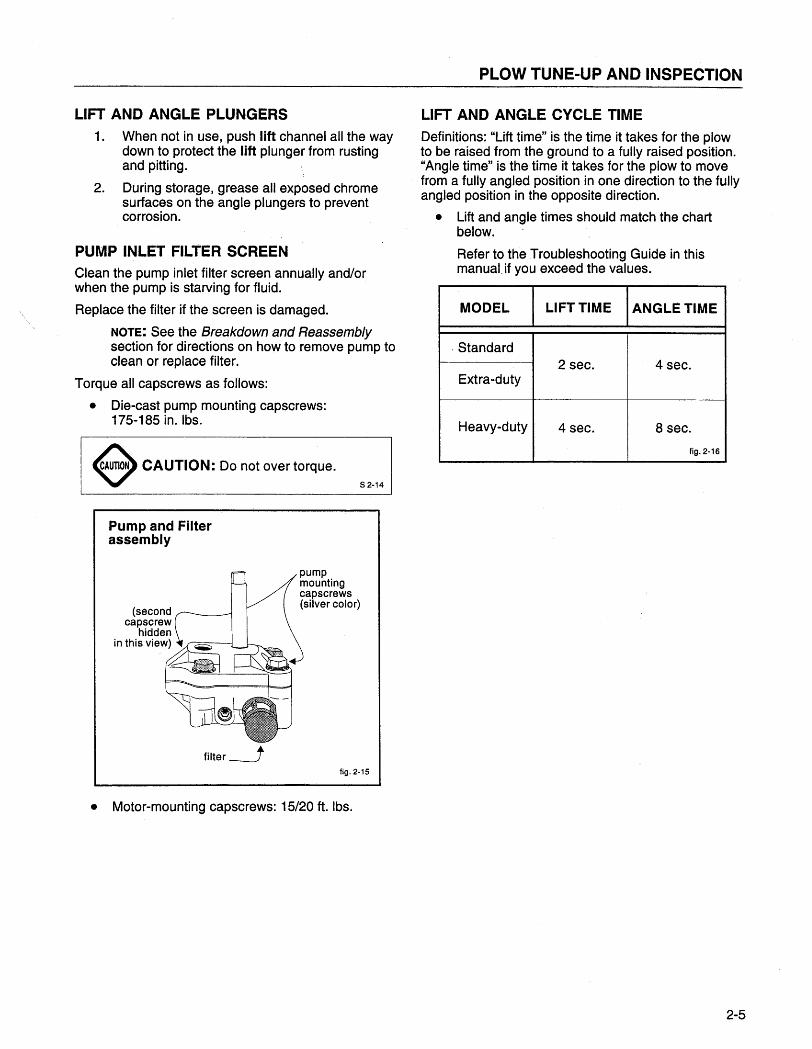
PUMP INLET FILTER SCREENClean the pump inlet filer screen annually and/orwhen the pump is starving for fluid.
Replace the filter if the screen is damaged.
NOTe: See the Breakdown and Reassemblysection for directions on how to remove pump toclean or replace filter.
Torque all capscrews as follows:
. Die-cast pump mounting capscrews:175-185 in. Ibs.
~ CAUtiON: Do not over torque.S 2-14
Pump and Filterassembly
filter --fig. 2-15
. Motor-mounting capscrews: 15/20 ft. Ibs.
LIFT AND ANGLE CYCLE TIMEDefinitions: "Lift time" is the time it takes for the plowto be raised from the ground to a fully raised position."Angle time" is the time it takes for the plow to movefrom a fully angled position in one direction to the fullyangled position in the opposite direction.
. Lift and angle times should match the chart
below.
Refer to the Troubleshooting Guide in thismanual,if you exceed the values.
MODEL LIFT TIME ANGLE TIME
. Standard
I2 sec. 4 sec.Extra-duty
Heavy-duty 4 sec. 8 sec.
fig. 2-16
2-5
ISARMATICCW Mark Ilia · Cable
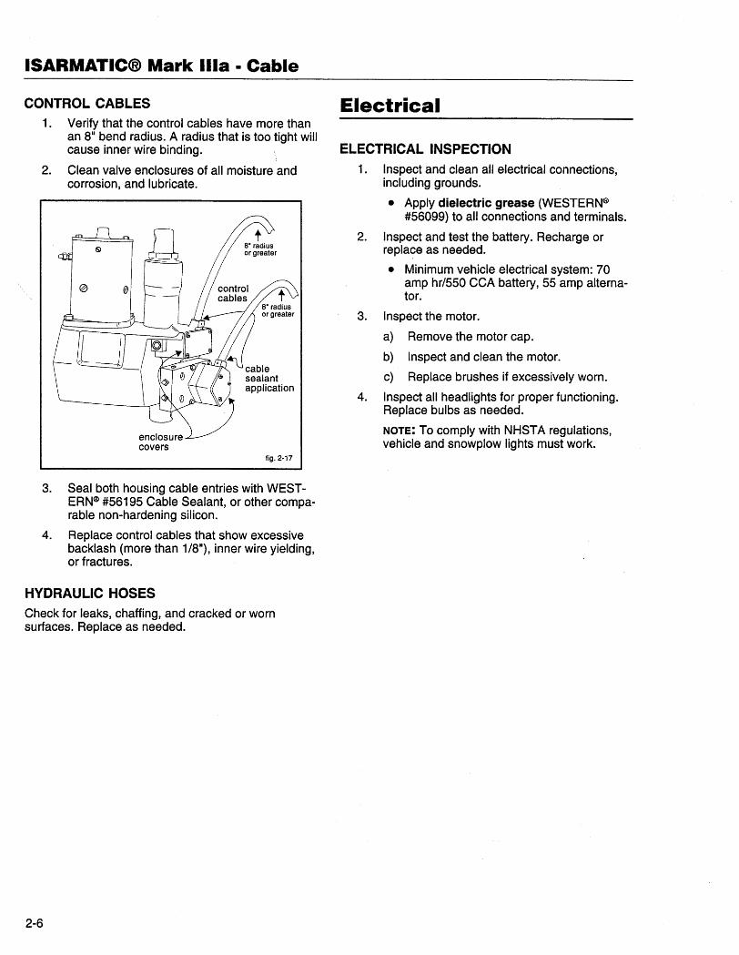
CONTROL CABLES1. Verify that the control cables have more than
an 811 bend radius. A radius that is too tight willcause inner wire binding.
2. Clean valve enclosures of all moisture and
corrosion, and lubricate.
fig. 2-17
3. Seal both housing cable entries with WEST-
ERN~ #56195 Cable Sealant, or other compa-rable non-hardening silcon.
4. Replace control cables that show excessive
backlash (more than 1/8"), inner wire yielding,or fractures.
HYDRAULIC HOSES
Check for leaks, chaffing, and cracked or wornsurfaces. Replace as needed.
2-6
Electrical
ELECTRICAL INSPECTION
1. Inspect and clean all electrical connections,
including grounds.
. Apply dielectric grease (WESTERN~#56099) to all connections and terminals.
2. Inspect and test the battery. Recharge or
replace as needed.
. Minimum vehicle electrical system: 70amp hr/550 CCA battery, 55 amp alterna-tor.
3. Inspect the motor.
a) Remove the motor cap.
b) Inspect and clean the motor.
c) Replace brushes if excessively worn.
4. Inspect all headlights for proper functioning.
Replace bulbs as needed.
NOTE: To comply with NHSTA regulations,vehicle and snowplow lights must work.
PLOW TUNE-UP AND INSPECTION
Snowplow Accessories
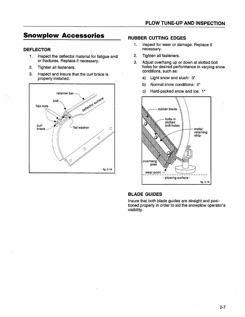
DEFLECTOR1. Inspect the deflector material for fatigue and/
or fractures. Replace if necessary.
2. Tighten all fasteners.
3. Inspect and insure that the curl brace is
properly installed.
curlbrace
fig. 2-1 B
RUBBER CUTTING EDGES1. Inspect for wear or damage. Replace if
necessary .
2. Tighten all fasteners.
3. Adjust oVérhang up or down at slotted boltholes for desired performance in varying snowconditions, such as:
a) Light snow and slush: 311
b) Normal snow conditions: 2"
c) Hard-packed snow and ice: 1 II
metalretainingstrip
- ~~~~p~~! ~ - - - - - - - - - - - - - - - --- plowing surface -
fig. 2-19
BLADE GUIDES
Insure that both blade guides are straight and posi-tioned properly in order to aid the snowplow operator'svisibility.
2-7
ISARMATIC(B Mark Ilia · Cable
2-8
DESCRIPTION OF MAJOR COMPONENTS
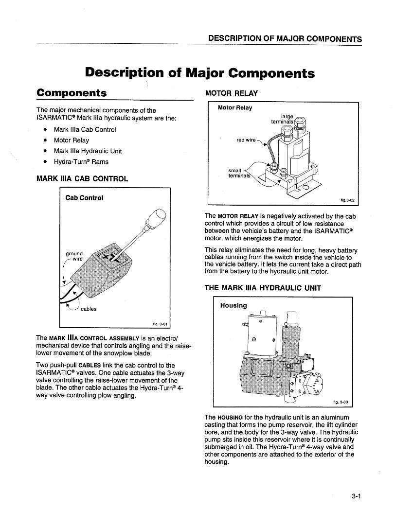
Description of Major ComponentsComponentsThe major mechanical components of theISARMATIC~ Mark ilia hydraulic system are the:
. Mark Ilia Cab Control
. Motor Relay
. Mark ilIa Hydraulic Unit
. Hydra-Turn~ Rams
MARK ilA CAB CONTROL
Cab Control
fig. 3-01
The MARK IliA CONTROL ASSEMBLY is an electro/mechanical device that controls angling and the raise-lower movement of the snowplow blade.
Two push-pull CABLES link the cab control to theISARMA TIC~ valves. One cable actuates the 3-wayvalve controlling the raise-lower movement of theblade. The other cable actuates the Hydra-Turn~ 4-way valve controlling plow angling.
MOTOR RELAY
Motor Relay
fig.3-02
The MOTOR RELAY is negatively activated by the cabcontrol which provides a. circuit of low resistancebetween the vehicle's battery and the ISARMA TIC~motor, which energizes the motor.
This relay eliminates the need for long, heavy batterycables running from the switch inside the vehicle tothe vehicle battery. It lets the current take a direct pathfrom the battery to the hydraulic unit motor.
THE MARK ilA HYDRAULIC UNIT
Housing
fig. 3-03
The HOUSING for the hydraulic unit is an aluminumcasting that forms the pump reservoir, the lift cylinderbore, and the body for the 3-way valve. The hydraulicpump sits inside this reservoir where it is continuallysubmerged in oiL. The Hydra-Turn~ 4-way valve andother components are attached to the exterior of thehousing.
3-1

ISARMATIC(B Mark Ilia · Cable
Electric Motor
fig. 3-04
The ELECTRIC MOTOR powers the hydraulic pump. It isa 12-volt DC motor, similar to some automobile startermotors. It consists of a steel frame with attachedfields, armature, brush assembly, cover cap, andmounting flange.
Hydraulic Pump
fig. 3-05
The HYDRAULIC PUMP is located directly under themotor in the reservoir providing the fluid flow neces-sary to operate the hydraulic rams.
3-2
Pressure Relief Valveand Filter Screen
filterscreen
fig. 3-06
The pump contains a PRESSURE RELIEF VALVE.
Located in the pump outlet passageway, it consists ofa ball, a spring, and an adjusting screw which relievesexcessive system pressure, protecting the pump andother components from damage.
The pump also contains a FILTER SCREEN which
protects the system from contaminated fluid. This filterscreen must be kept clean at all times. Under nocircumstances should the pump run without this filterscreen installed.
3-Way Lift Lower Valve
fig. 3-07
The 3-WAY LIFT I LOWER VALVE is located in thehydraulic housing, to the right of the nameplate. Itcontrols the raise/lower movement of the snowplowblade and is mechanically operated by the cab controlcable assembly.
DESCRIPTION OF MAJOR COMPONENTS
4-Way Hydra- Turn~Valveand Cushion Valves
, 4-WayHYdravj
passenger's side jcushion valve
driver's side cushion valve(on bottom) fig. 3-08
The 4-WAY HYDRA-TURNCß VALVE is attached to thehydraulic housing, directly below the 3-way valve. Itcontrols plow angling and is mechanically operated bya cable linked to the cab control.
The CUSHION VALVES (cross-over relief valves) arelocated in the Hydra-Turn(8Valve manifold. They actas an impact absorbing device, protecting both thevehicle and plow when an immovable object is struckby the blade.
Lift Ram Assembly
fig. 3-09
The LIFT RAM ASSEMBLY is a single acting, hydraulicram with a 6-inch stroke. It is built into the housingand provides lifting.
HYDRA-TURN~ RAMS
Hydra-Turn Ram~ Assembly
fig. 3-10
The HYDRA-TURNCß RAMS are single-acting hydrauliccylinders, having a 10-inch stroke (16-inches on theHeavy Duty model) that provides angling.
The QUICK COUPLERS provide a quick way to connectand disconnect the Hydra- Turn(8 hoses for snowplowinstallation and removaL.
3-3
ISARMATIC(B Mark Ilia · Cable
RAISING PLOWTheory of OperationThe ISARMATIC8 Mark Ilia Hydraulic System pro-vides power to raise and angle the plow.
Raising, and angling to the right and left are accom-plished by electrical and mechanical means. Loweringoperates only by mechanical means.
ELECTRICAL
Electric SchematicGrounded through engine block
or direct to battery----_.--
!l1f
ground(through control
cables) -=
- Primary (low current)
.',','..,',,"',',', Secondary (high current)- ---- Jumper Wire & second
small terminal
3 positionswitch
fig. 3-11
When the cab control is in the RAISE, LEFT (L), ORRIGHT (R) position, contacts inside the control are
grounded through the control cables to the hydraulicunit, completing the grounding of the motor relay(primary) circuit, which energizes the motor relay coiL.
The energized relay coil causes the contacts insidethe motor relay to close, completing the battery/motor(secondary) circuit. A direct, low resistance current
, path is now available to energize the electric motor.
Current flows through the motor and back to thebattery via the ground cable.
3-4
Raising Plow
3-way valver-----------------,i Shuttle moves .- i: Blocks passage to reservoir. ii oil flow unseats check ball. :i check i: shuttie. r- ball:
~ r _-_-, - - - - tk - - - - - - J
lift ram
JJJ
4-wayvalve
Reservoir i____________..
fig. 3-12
Moving the ilia cab control to the RAISE (R) position
activates the motor relay, energizing the motor. Thecable moves the shuttle into the lift valve. This actioncloses the passageway to the reservoir and directsfluid flow from the pump outlet to the lift ram.
Oil passes through the 4-way Hydra-Turn8 valve andinto the 3-way liftlower valve. Oil flows around theshuttle stem and pushes the check valve ball off itsseat. There it enters the lift ram assembly, pushing theplunger (and the snowplow) up.
DESCRIPTION OF MAJOR COMPONENTS
LOWERING PLOW ANGLING PLOW TO RIGHT OR LEFT
Lowering Plow
3-way valver-----------------ii Shuttle moves --: Shuttle unseats check ball: i
i Opens passage to reservoir. ii ' ~e~ i: shuttie. r- ball:
~W~-- - ,
\m:ipump
Pump doesnot runwhile "",.,'..",,' ilowering. i
_ _ _ _ _ --!~s~!~oJr..
lift ram
tl
'~.;..;o .
JJJ
4-wayvalve
fig. 3.13
Moving the Ilia cab control to the LOWER (L) (float)position moves the shuttle stem to push the checkvalve ball off its seat allowing the snowplow weight topush oil back into the reservoir. The motor does notoperate.
1. Angling Right
3-way valver - - - - - - - - - - - - - - - - - i lift rami Shutte centers. Check ball i
: blocks flow to lift ram. :i Passage open to reservoir. i
: (cheek:i 't ball iI ~~ Jr-_-,- - -'l~ - ~ - - -_I~~~~=-=Dfcol.
pu~r:::!::::: :
:' i=';"':':::*: I
Reservoir :4-wayvalve
(shifted)____________-.
2. Angling Left3-way valve
r - - - - - - - - - - - - - - - - - i lift rami Shuttle centers. Check ball i
: blocks flow to lift ram. :i Passage open to reservoir. ii check i: shuttle -. r- ball:
~ jf~~-, - - -~L - ~ - - ~
~rIpump It :
;,':"'i,:,; i¡:;::.:.:.:~ :
Hydra-Turn iB ¥"rams
4-way valvesvalve
(shifted)
Reservoir :_____________-.
fig. 3-14
Moving the ilia cab control to the RIGHT (R) position
rotates the rotor 45° clockwise so the recessedpockets provide passages between the pump supplyand left hydraulic ram and the reservoir port. Oil fromthe pump flows through the 4-way valve and entersthe left hydraulic ram. As the ram extends, the plowangles to the right. As the plow angles, the righthydraulic ram collapses, pushing oil through the 4-wayvalve and past the shuttle in the 3-way valve to thereservoir.
3-5
ISARMATICCW Mark Ilia · Cable
4-Way Hydra- Turn(ßValve
manifold
Top view of rotor shownin curp-side position angle.
CD Oil from the collapsing cylinder is pushed. . .
reservoir port
Side view of rotor.recessedpOCkets~..,.,
LÔ fig. 3-15
Moving the ilia cab control to the LEFT (L) positionstarts the rotor 45° counterclockwise from neutral, sothat the oil from the pump flows through the 4-wayvalve and enters the right Hydra- Turn(ß ram. As the
3-6
ram extends, the plow angles to the left. The leftHydra-Turn(ß ram collapses, pushing oil past theshuttle in the 3-way valve to the reservoir.
Top view of roter shown indriver-side position angle.
(g . . . into the extending cylinder.
pumpsupplyport reservoir port
CD Oil from the collapsing cylinder is pushed. . .
fig. 3-16
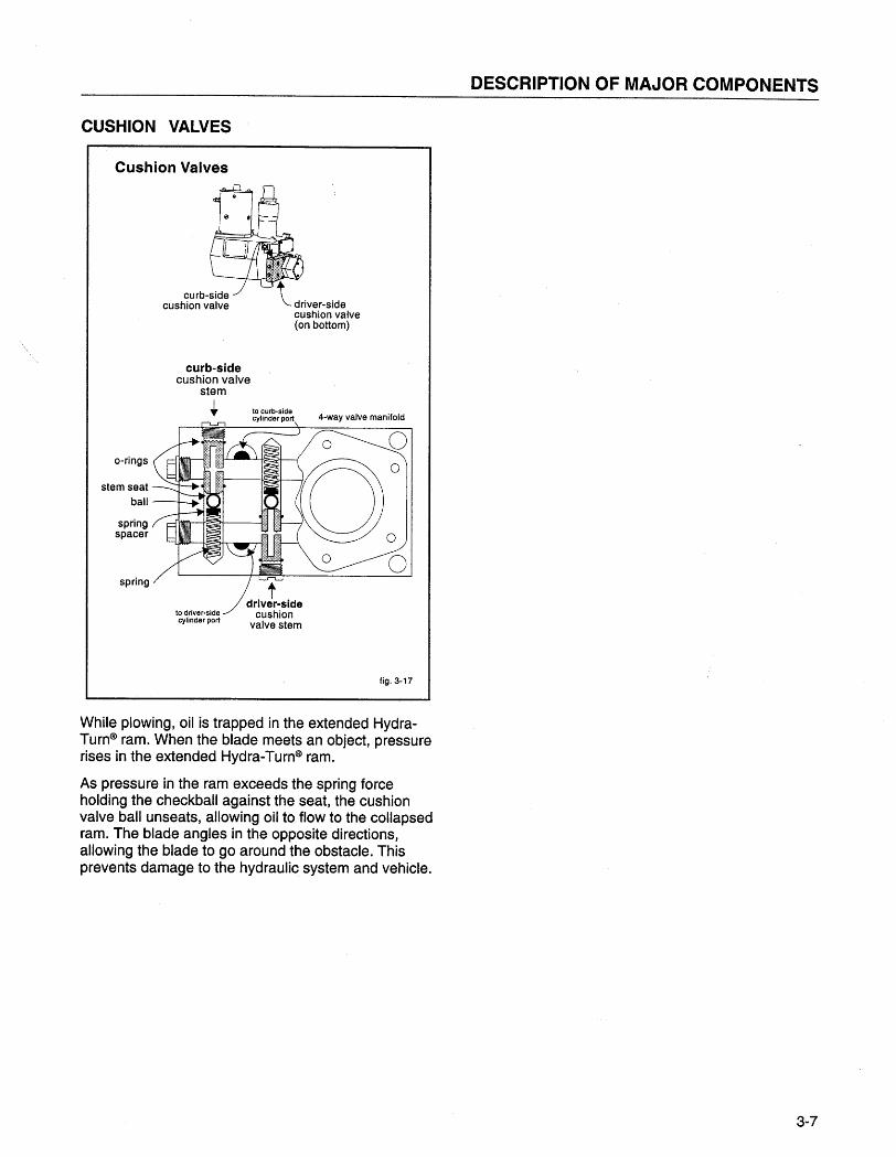
CUSHION VALVES
DESCRIPTION OF MAJOR COMPONENTS
Cushion Valves
t driver-side
cushion valve
(on bottom)
curb-sidecushion valve
stem
. to curb-sidecylinder port 4-way valve manifold
o-rings
stem seat
ball
springspacer
spring
to driver-sidecylinder port
fig, 3-17
While plowing, oil is trapped in the extended Hydra-Turn~ ram. When the blade meets an object, pressurerises in the extended Hydra-Turn~ ram.
As pressure in the ram exceeds the spring forceholding the checkball against the seat, the cushionvalve ball unseats, allowing oil to flow to the collapsedram. The blade angles in the opposite directions,allowing the blade to go around the obstacle. Thisprevents damage to the hydraulic system and vehicle.
3-7
ISARMATIC(B Mark Ilia · Cable
3-8

TROUBLESHOOTING SECTION
Troubleshooting SectionMost service can be performed with the hydraulic unit left on the vehicle. This saves time and aids in the evalua-tion of the entire system, which includes the electrical system, cables, Mark ila cab control, etc.
AWARNING: Do NOT stand between the vehicle and blade, or directly in front ofthe blade when it is being raised, lowered, or angled. Clearance between thevehicle and the blade decreases as the blade is operated. Serious bodily injurycan result from the blade striking a body or dropping on the feet or hands.
S 4-01
Troubleshooting Guideila
ControlPosition Problem Description Define Problem and Follow Steps Indicated
Angle Blade will not angle or angles Verify Adjust Checktoo slowly. Time: 4 seconds. 4-way lift valve disconnect(8 seconds - Heavy Duty) valve out. couplers
lever See andtravel. (F & F1) hydraulic
Motor Check All See ram nuts. Removedoes oil functions (E) pump.
not run. leveL. are slow. CleanRaise Blade will not raise or raises See (B) See (A) Verify Adjust Check lift filter
too slowly. Time: 2 seconds. 3-way lift ram packing screen.(4 seconds - Heavy Duty) valve valve nut adjust.
lever in. Refer totravel. See Plow TuneSee (F & F1) Up&:(D) Inspection
section. -Neutral Blade wil not remain angled
..while plowing. Inspect and adjust cushion valves. See (C)
Neutral Motor continues to run in Dis- It motor runs, motor relay is shorted.Further troubleshootingrequires the use of test
neutral. connect Replace motor relay. equipment.ilia
control See an authorizedwire It motor stops, short is in primary (ilIa Western Distributor,from control) circuit. Isolate and repair.motor orrelay.
Refer to the Western
Angle Blade raises while angling. Verify Adjust lift valve out. See (F & F1)Hydra-Lectric1m Test Kit,
and/or a Western3-way Hydraulic Servicevalve School Video.lever
Remove check valve.Neutral Blade lowers in neutral. travel. Adjust check valveSee out. See (F & F2) Inspect O-ring and
(D) seat. Refer toBreakdown and
Lower Blade lowers too fast. Reassembly section.
Lower Blade will not lower, or Adjust check valve Check lift ram packinglowers too slowly. in. See (F & F2) nut adjustment. Refer
ito Plow Tune-Up &Inspection section. fig. 4-02
4-1
ISARMATICCB Mark Ilia · Cable
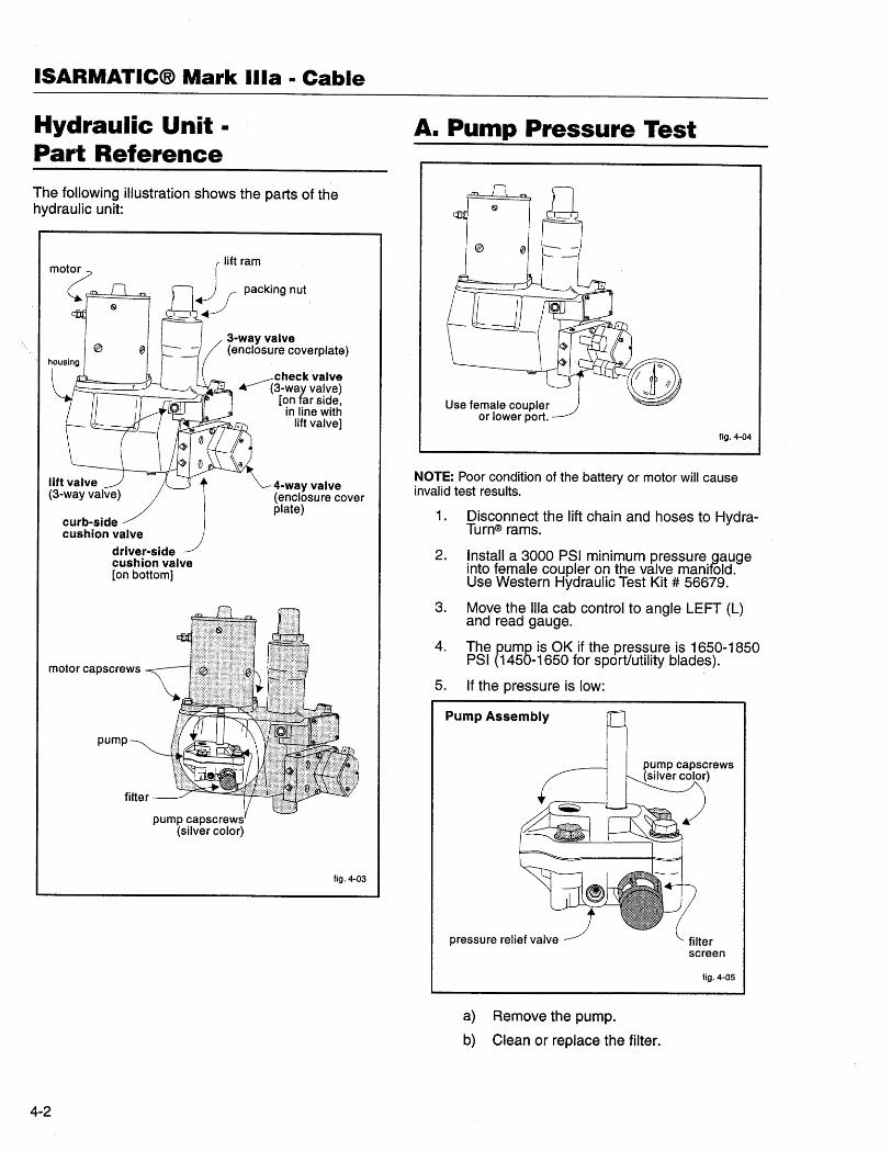
Hydraulic Unit ·
Part ReferenceThe following illustration shows the parts of thehydraulic unit:
lit ram
_ _ :! packing nul
3-way valve(enclosure coverplate)
check valve.-3-way valve)
(on far side,in line with
lift valve)
lift valve J(3-way valve)
curb-sidecushion valve
driver-sidecushion valve
(on bottom)
4-way valve
(enclosure coverplate)
motor capscrews
pump
pump capscrews(silver color)
fig. 4-03
4-2
A. Pump Pressure Test
Use female coupleror lower port.
fig. 4-04
NOTE: Poor condition of the battery or motor will causeinvalid test results.
1. Disconnect the lift chain and hoses to Hydra-Turn(8 rams.
Install a 3000 PSI minimum pressure gaugeinto female coupler on the valve manifõld.Use Western Hydraulic Test Kit # 56679.
Move the ila cab control to angle LEFT (L)and read gauge.
The pump is OK if the pressure is 16.50-1850PSI (1450-1650 for sport/utility blades).
If the pressure is low:
2.
3.
'4.
5.
Pump Assembly
filterscreen
fig. 4-05
a) Remove the pump.
b) Clean or replace the filter.

TROUBLESHOOTING SECTION
c) Adjust the pressure relief valve. 1/4 turnequals approximately 225 PSI.
d) Re-assemble. The pump capscrewsrequire 175/185 in. Ibs. torque. The motorcapscrews require 15/20 ft. Ibs torque.
Motor Relay to motor
· Check to see if the ilIa control isgrounded (through push-pull cables).
b) If the motor does not run:
· Use a jumper wire to connect thePOS + terminal of the battery to thesmall terminal with RED wire attachedon the motor relay.
· Operate the ilia control to RAISE,angle LEFT or RIGHT.
c) If the motor then runs, check for broken
or damaged RED wire on the relay.
d) If the motor still does not run, use heavy,
jumper cables to jump the two large .terminals on top of the motor relay.
e) If the motor runs, replace the motor relay.
f) If the motor does not run:
· Remove the motor.
· Check the pump shaft rotation.
· If the pump shaft is tight, repair orreplace the pump.
· If the pump shaft is loose, replacethe motor.
B. Relay Test
fig. 4-06
NOTE: Perform this test if the motor does not run withilIa cab control in RAISE, ANGLE RIGHT (R), or ANGLE LEFT
(L). Battery has sufficient charge to start the engine.
1. Disconnect the lift chain and hoses to theHydra- Turn(ß rams.
2. Check all electrical cables and connections,including grounds. Clean and tighten, ifnecessary .
AWARNING: Protect the top of thebattery. Sparks from testing operationscould cause battery gases to explodecausing severe eye or body burns, orother personal injuries.
S4-07
3. Use a jumper wire to connect the small
terminal with BLACK wire on the motor rèlay to
the NEG - terminal of the battery.
a) If the motor runs, the problem is in the iliacontrol (primary) circuit.
· Check for broken wire, loose connec-tions, or bent contacts in the ilia cabcontrol.
4-3
ISARMATIC(B Mark Ilia · Cable
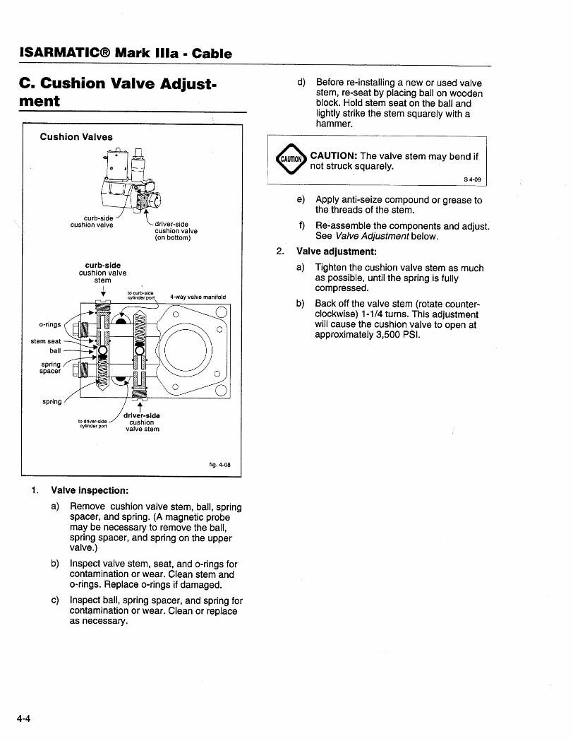
c. Cushion Valve Adjust-ment
Cushion Valves
a-rings
stem seat
ball
springspacer
curb-sidecushion valve
stemI.. to curb-side
cylinder port 4-way valve manifold
spring
to dnver-sidecylinder port
fig. 4-08
1. Valve inspection:
a) Remove cushion valve stem, ball, springspacer, and spring. (A magnetic probemay be necessary to remove the ball,spring spacer, and spring on the uppervalve. )
b) Inspect valve stem, seat, and o-rings for
contamination or wear. Clean stem ando-rings. Replace o-rings if damaged.
c) Inspect ball, spring spacer, and spring for
contamination or wear. Clean or replaceas necessary.
4-4
d) Before re-installing a new or used valve
stem, re-seat by placing ball on woodenblock. Hold stem seat on the ball andlightly strike the stem squarely with ahammer.
~ CAUTION: The valve stem may bend if
n not struck squarely.S 4-09
2.
e) Apply anti-seize compound or grease to
the threads of the stem.
f) Re-assemble the components and adjust.
See Valve Adjustment below.
Valve adjustment:
a) Tighten the cushion valve stem as much
as possible, until the spring is fullycompressed.
b) Back off the valve stem (rotate counter-clockwise) 1-1/4 turns. This adjustmentwil cause the cushion valve to open atapproximately 3,500 PSI.
TROUBLESHOOTING SECTION
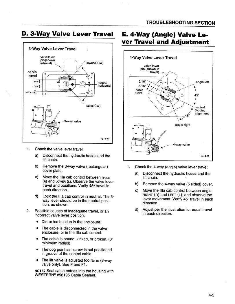
D. 3-Way Valve Lever Travel
3-Way Valve Lever Travel
valve lever
pin (shownin travel)
cabletravel o
5/16' ¡
5/16. ¡
l1/16"101/18"
l'
neutralhorizontal
raise (CW)
fig. 4-10
1. Check the valve lever travel:
a) Disconnect the hydraulic hoses and the
lift chain.
b) Remove the 3-way valve (rectangular)cover plate.
c) Move the ilia cab control between RAISE
(R) and LOWER (L). Observe the valve levertravel and positions. Verify 45° travel ineach di rection..
d) Lock the ilia cab control in neutral. The 3-way lever should be in the neutral posi-tion, as shown.
2. Possible causes of inadequate travel, or an
incorrect valve lever position:
. Dirt or ice buildup in the enclosure.
· The cable is disconnected in the valveenclosure, or in the Ilia cab control.
· The cable is bound, kinked, or broken. (811
minimum radius)
· The dog point set screw is not positionedin groove of the control cable.
. The lift valve is adjusted too far in (3-wayvalve only). See F and F1.
NOTE: Seal cable entries into the housing withWESTERNCI #56195 Cable Sealant.
E. 4-Way (Angle) Valve Le-ver Travel and Adjustment
4-Way Valve Lever Travel
valve leverpin (shown in
travel)
5/16"5/16" II
cabletravel
angle left
neutral3-pointalignment
angle right
fig. 4-11
1. Check the 4-way (angle) valve lever travel:
a) Disconnect the hydraulic hoses and the
lift chain.
b) Remove the 4-way valve (5 sided) cover.
c) Move the Ilia cab control between angleRIGHT (R) and LEFT (L), and observe the
lever movement. Verify 45° travel in eachdirection.
d) Adjust per the illustration for equal travelin each direction.
4-5
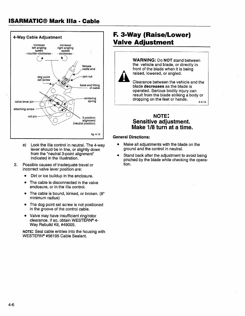
ISARMATIC(B Mark Ilia · Cable
4-Way Cable Adjustment
increaseleft angling
speed- counter-clockwise -
increaseright angling
speed- clockwise -
Ùú
base end fittingof cable
valve lever pincentering
spring
attaching screw
3-positionalignment
(neutral position)
fig. 4-12
e) Lock the Ilia control in neutral. The 4-waylever should be in line, or slightly downfrom the "neutral 3-point alignment"indicatec; in the illustration.
2. Possible causes of inadequate travel or
incorrect valve lever position are:
. Dirt or ice buildup in the enclosure.
. The cable is disconnected in the valve
enclosure, or in the Ilia control.
. The cable is bound, kinked, or broken. (8"
minimum radius)
. The dog point set screw is not positionedin the groove of the control cable.
. Valve may have insufficient ring/rotorclearance. If so, obtain W~STERN(ß 4-Way Rebuild Kit, #49005.
NOTE: Seal cable entries into the housing withWESTERN(ß #56195 Cable Sealant.
4-6
F. 3-Way (Raise/Lower)Valve Adjustment
AWARNING: Do NOT stand betweenthe vehicle and blade, or directly infront of the blade when it is beingraised, lowered, or angled.
Clearance between the vehi,cle and theblade decreases as the blade isoperated. Serious bodily injury canresult from the blade striking a body ordropping on the feet or hands.
S 4-13
NOTE:Sensitive adjustment.Make 1/8 turn at a time.
General Directions:
. Make all adjustments with the blade on the
ground and the control in neutral.
. Stand back after the adjustment to avoid being
pinçhed by the blade while checking the opera-tion.
TROUBLESHOOTING SECTION
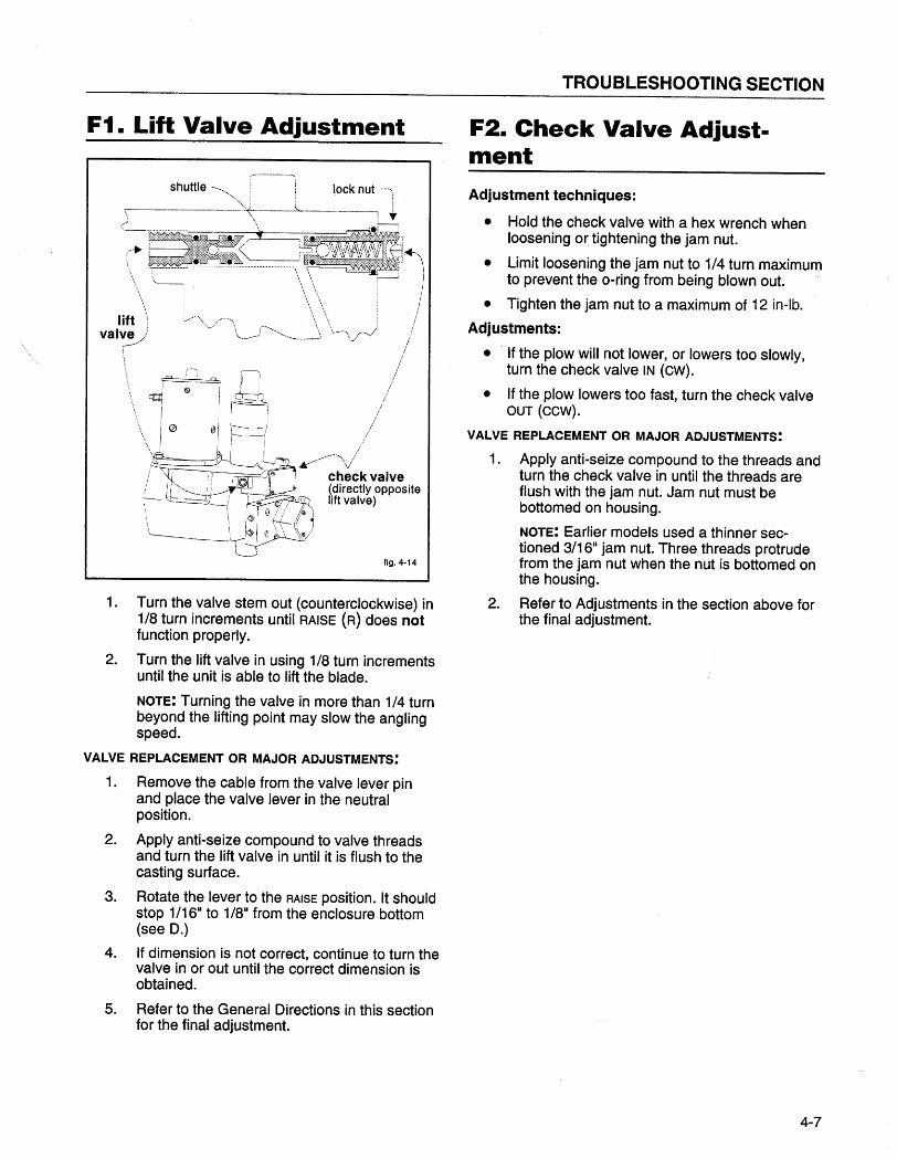
F1. Lift Valve Adjustment
--
,-......-----'.."ì
shuttle---_,'-. , lock nut ....-'1
-,._-~'\:,~-~----: l,
\
\\\ '\.- i;
/
/;
Jl 1111",1/~~!
011 \-- -)1- -I /¡ I I /\.é 11 i I /--'\ /Di ~_/"',~..// ,VII i ,'" U ~ i check valve, II '-,-___ ! I _"~i (directly opposite1-- ~~( l,-.. " lift valve), ø i ( ~
'i I~ I ~-- f .~~
lift 'ival~!-/j
~/'\
~r-ii is
~i
\\ I ø
fig, 4-14
1. Turn the valve stem out (counterclockwise) in
1/8 turn increments until RAISE (R) does notfunction properly.
2. Turn the lift valve in using 1/8 turn increments
until the unit is able to lift the blade.
NOTE: Turning the valve in more than 1/4 turnbeyond the lifting point may slow the anglingspeed.
VALVE REPLACEMENT OR MAJOR ADJUSTMENTS:
1. Remove the cable from the valve lever pinand place the valve lever in the neutralposition.
2. Apply anti-seize compound to valve threads
and turn the lift valve in until it is flush to thecasting surface.
3. Rotate the lever to the RAISE position. It should
stop 1/1611 to 1/811 from the enclosure bottom(see D.)
4. If dimension is not correct, continue to turn the
valve in or out until the correct dimension isobtained.
5. Refer to the General Directions in this section
for the final adjustment.
F2. Check Valve Adjust.mentAdjustment techniques:
· Hold the check valve with a hex wrench when
loosening or tightening the jam nut.
· Limit loosening the jam nut to 1/4 turn maximumto prevent the o-ring from being blown out.
· Tighten the jam nut to a maximum of 12 in-lb.
Adjustments:
· 'If the plow will not lower, or lowers too slowly,
turn the check valve IN (CW).
· If the plow lowers too fast, turn the check valveOUT (CCw).
VALVE REPLACEMENT OR MAJOR ADJUSTMENTS:
1. Apply anti-seize compound to the threads and
turn the check valve in until the threads areflush with the jam nut. Jam nut must bebottomed on housing.
NOTE: Earlier models used a thinner sec-tioned 3/16" jam nut. Three threads protrudefrom the jam nut when the nut is bottomed onthe housing.
2. Refer to Adjustments in the section above for
the final adjustment.
4-7
ISARMATIC(B Mark Ilia · Cable
4-8
BREAKDOWN AND REASSEMBLY
Breakdo\Nn and Reassembly
Repair Warranty Repair
GENERAL
This section contains shop repair proceduresfor the ISARMATICcP Mark iliA cable control.Before either of these parts are removed fromthe vehicle and disassembled for repair, besure the problem has been thoroughlychecked. (See troubleshooting guide in thismanuaL.) Most problems can be corrected
without the need to remove or disassemblethe unit.
SERIAL NUMBER AND RMO NUMBER
Be sure to include the serial number (locatedon the nameplate of the ISARMA TICcP unit)
with any warranty claim or Return MaterialOrder (RMO). When returning parts, includean RMO tag. An RMOtag can be obtainedfrom Western Products Customer ServiceDepartment.
Refer to Western Product's WARRANTYMANUAL which describes the warranty policyand procedures that should be followed forprocessing all waranty claims.
Flat labor rates have been developed to assistdistributors in calculating their labor costswhen requesting warranty labor. Refer tothese flat labor rates before performing eachoperation so that you allow the time alloted forthat operation.
HYDRAULIC PUMP AND HOUSING
Through the years, different pump mountingconfigurations have been used. All compo-nents are interchangeable between housings,except for the pump. When ordering servicehousing or pump, verify pump mountingconfiguration.
DISASSEMBLY
Always use brass jaws when clamping hy-draulic unit components in vise. All seals ando-rings should be replaced when major repairis performed. Use.WESTERNcP Extra DutySeal Kit #49049 and WESTERNcP Heavy DutySeal Kit #49050. Drain oil through drain plugat front bottom of main housing before disas-sembly.
REASSEMBLY AND INSTALLATION
To avoid damage to o-rings and seals, coatthem with oil and position them carefullybefore reassembly. Be sure to tighten fasten-ers to their proper torque value when thevalue is indicated in the procedure. After theISARMA TICcP unit has been reassembled,
install it on the vehicle and fill it with hydraulicfluid. (See the maintenance section of appro-priate owner's manuaL.) After final adjustmentsare completed, seal cable openings withWESTERNcP Cable Sealant #56195 to preventmoisture and dirt from entering the housings.Be sure setscrews are in the proper groove inthe cable fittings.
5-1
ISARMATIC(B Mark Ilia · Cable
Reference GuideWith Photos
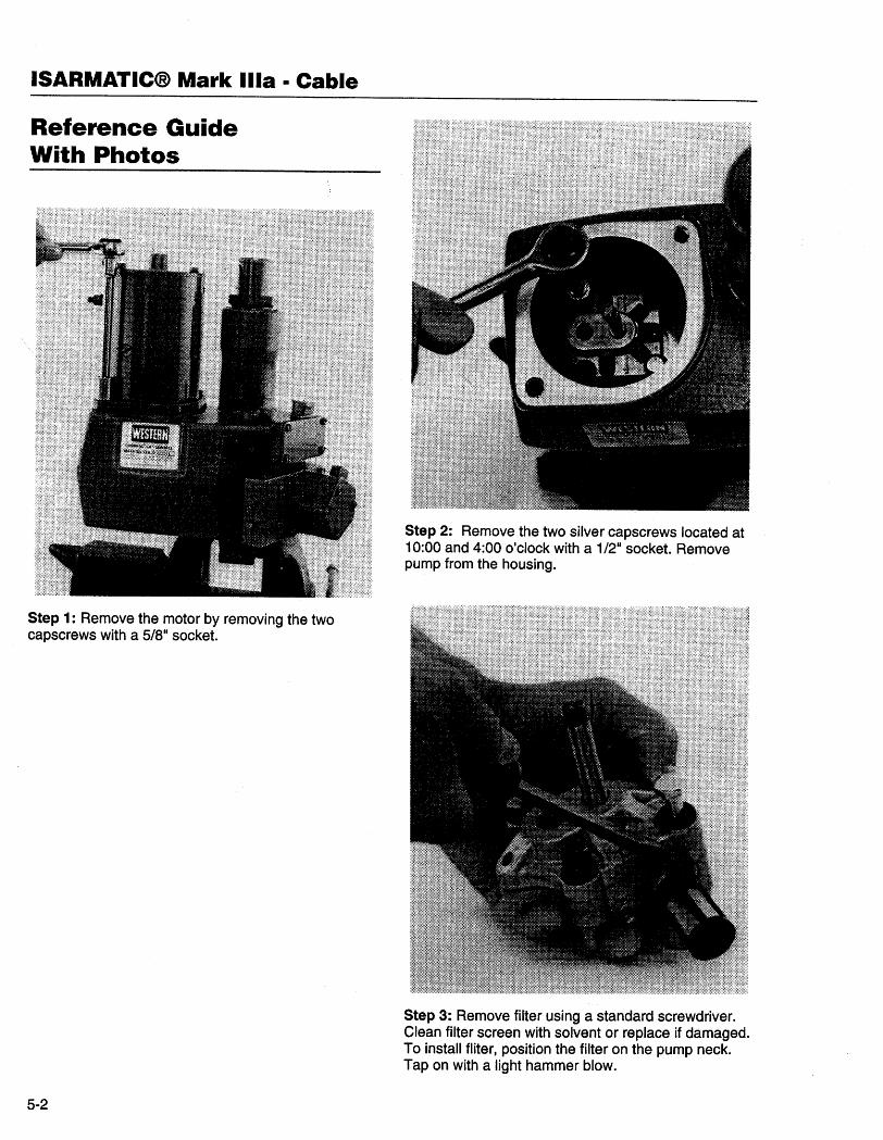
Step 1: Remove the motor by removing the twocapscrews with a 5/811 socket.
5-2
Step 2: Remove the two silver capscrews located at10:00 and 4:00 o'clock with a 1/211 socket. Removepump from the housing.
Step 3: Remove filter using a standard screwdriver.Clean filter screen with solvent or replace if damaged.To install fliter, position the filter on the pump neck.Tap on with a light hammer blow.
BREAKDOWN AND REASSEMBLY
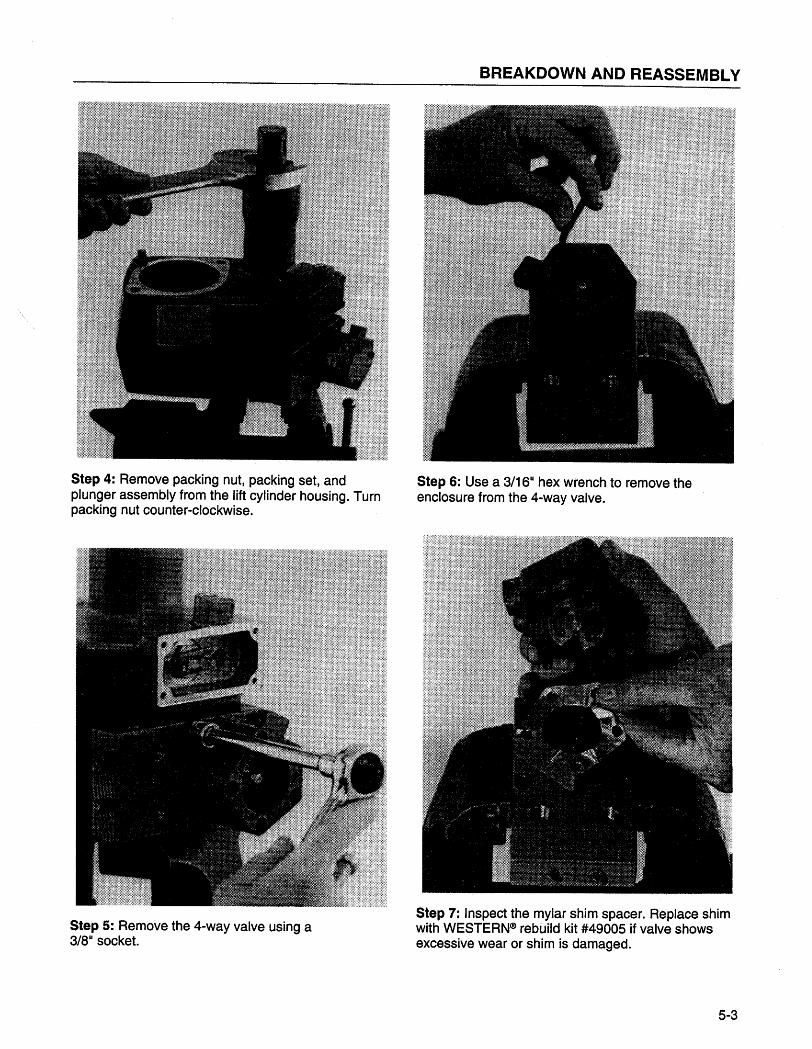
Step 4: Remove packing nut, packing set, andplunger assembly from the lift cylinder housing. Turnpacking nut counter-clockwise.
Step 5: Remove the 4-way valve using a3/811 socket.
Step 6: Use a 3/1611 hex wrench to remove theenclosure from the 4-way valve.
Step 7: Inspect the mylar shim spacer. Replace shimwith WESTERNCã rebUild kit #49005 if valve showsexcessive wear or shim is damaged.
5-3
ISARMATIC(8 Mark Ilia · Cable
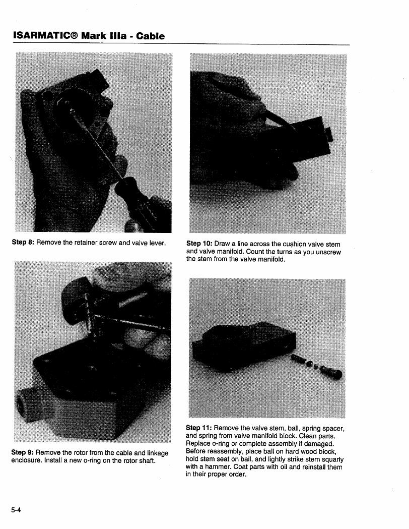
Step 8: Remove the retainer screw and valve lever.
Step 9: Remove the rotor from the cable and linkageenclosure. Install a new o-ring on the rotor shaft.
5-4
Step 10: Draw a line across the cushion valve stemand valve manifold. Count the turns as you unscrewthe stem from the valve manifold.
Step 11: Remove the valve stem, ball, spring spacer,and spring from valve manifold block. Clean parts.Replace o-ring or complete assembly if damaged.Before reassembly, place ball on hard wood block,hold stem seat on ball, and lightly strike stem squarlywith a hammer. Coat parts with oil and reinstall themin their proper order.
BREAKDOWN AND REASSEMBLY
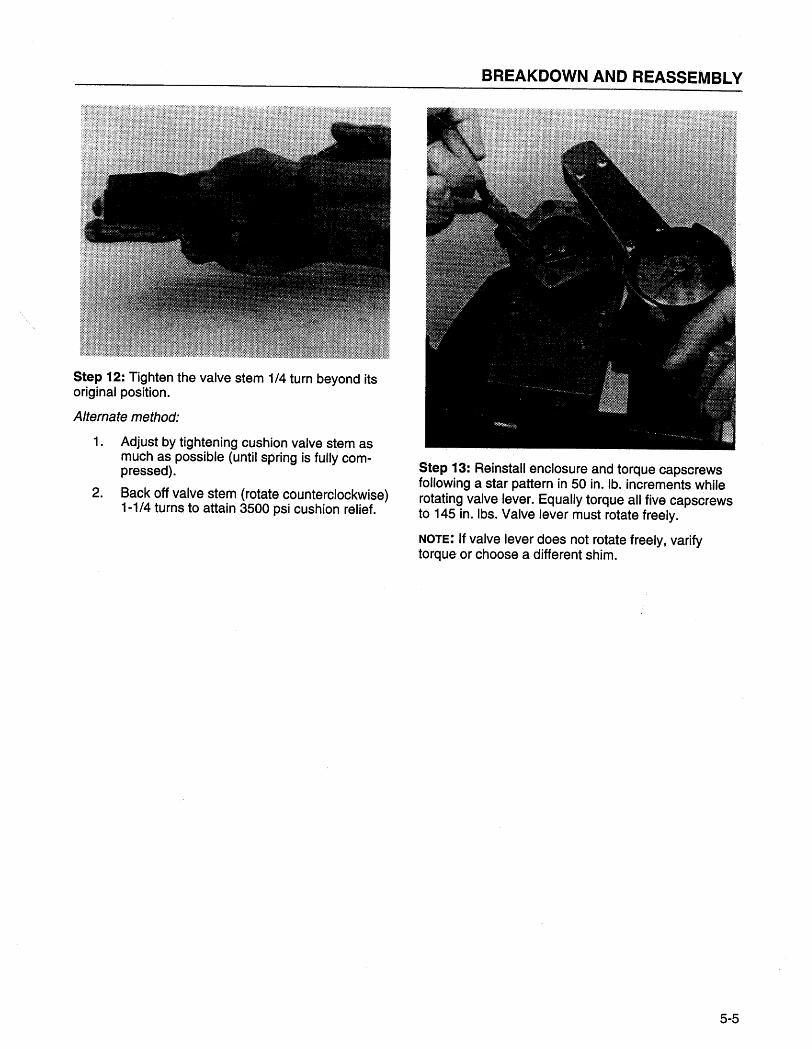
Step 12: Tighten the valve stem 1/4 turn beyond itsoriginal position.
Alternate method:
1. Adjust by tightening cushion valve stem as
much as possible (until spring is fully com-pressed).
2. Back off valve stem (rotate counterclockwise)
1-1/4 turns to attain 3500 psi cushion relief.
Step 13: Reinstall enclosure and torque capscrewsfollowing a star pattern in 50 in. lb. increments whilerotating valve lever. Equally torque all five capscrewsto 145 in. Ibs. Valve lever must rotate freely.
NOTE: If valve lever does not rotate freely, varifytorque or choose a different shim.
5-5
ISARMATIC(B Mark Ilia · Cable
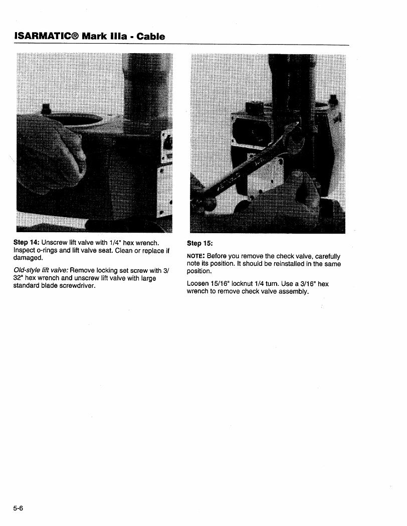
Step 14: Unscrew lift valve with 1/4" hex wrench. .Inspect o-rings and lift valve seat. Clean or replace ifdamaged.
Old-style lift valve: Remove locking set screw with 3/32" hex wrench and unscrew lift valve with largestandard blade screwdriver.
5-6
Step 15:
NOTE: Before you remove the check valve, carefullynote its position. It should be reinstalled in the sameposition.
Loosen 15/16" locknut 1/4 turn. Use a 3/16" hexwrench to remove check valve assembly.
BREAKDOWN AND REASSEMBLY
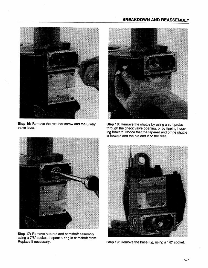
Step 16: Remove the retainer screw and the 3-wayvalve lever.
Step 17: Remove hub nut and camshaft assemblyusing a 7/8" socket. Inspect o-ring in camshaft stem.Replace if necessary.
Step 18: Remove the shuttle by using a soft probethrough the check valve opening, or by tipping hous-ing forward. Notice that the tapered end of the shuttleis forward and the pin end is to the rear.
Step 19: Remove the base lug, using a 1/2" socket.
5-7
ISARMATIC(B Mark Ilia · Cable
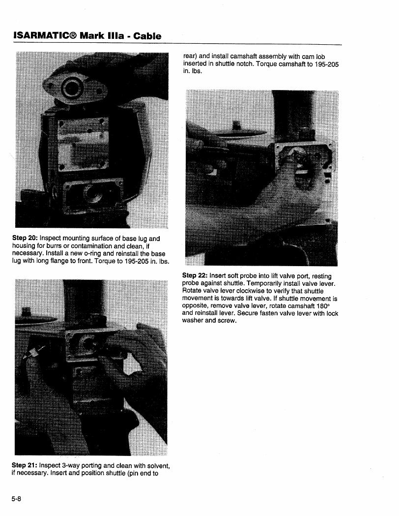
Step 20: Inspect mounting surface of base lug andhousing for burrs or contamination and clean, ifnecessary. Install a new o-ring and reinstall the baselug with long flange to front. Torque to 195-205 in. Ibs.
Step 21: Inspect 3-way porting and clean with solvent,if necessary. Insert and position shuttle (pin end to
5-8
rear) and install camshaft assembly with cam lobinserted in shuttle notch. Torque camshaft to 195-205in.lbs.
Step 22: Insert soft probe into lift valve port, restingprobe against shuttle. Temporarily install valve lever.Rotate valve lever clockwise to verify that shuttlemovement is towards lift valve. If shuttle movement isopposite, remove valve lever, rotate camshaft 1800and reinstall lever. Secure fasten valve lever with lockwasher and screw.
BREAKDOWN AND REASSEMBLY
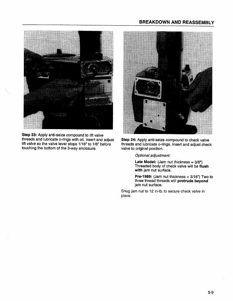
Step 23: Apply anti-seize compound to lift valvethreads and lubricate o-rings with oiL. Insert and adjustlift valve so the valve lever stops 1/16'. to 1/BII beforetouching the bottom of the 3-way enclosure.
Step 24: Apply anti-seize compound to check valvethreads and lubricate o-rings. Insert and adjust checkvalve to original position.
Opüonal adjustment
Late Model: (Jam nut thickness = 3/B")Threaded body of check valve will be flushwith jam nut surface.
Pre-1989: (Jam nut thickness = 3/16") Two tothree thread threads wil protrude beyondjam nut surface.
Snug jam nut to 12 in-lb. to secure check valve inplace.
5-9
ISARMATIC(B Mark Ilia · Cable
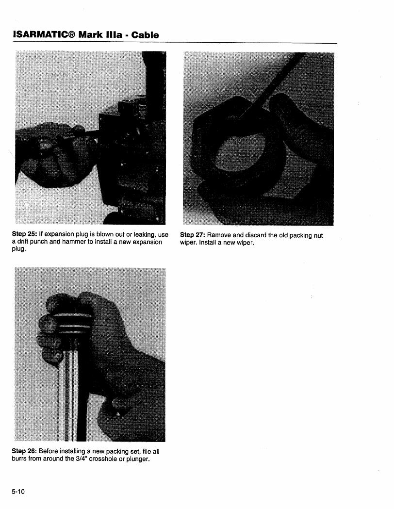
Step 25: If expansion plug is blown out or leaking, usea drift punch and, hammer to install a new expansionplug.
Step 26: Before installng a new packing set, file allburrs from arolJnd the 3/411 crossholeor plunger.
5-10
Step 27: Remove and discard the old packing nutwiper. Install a new wiper.
BREAKDOWN AND REASSEMBLY
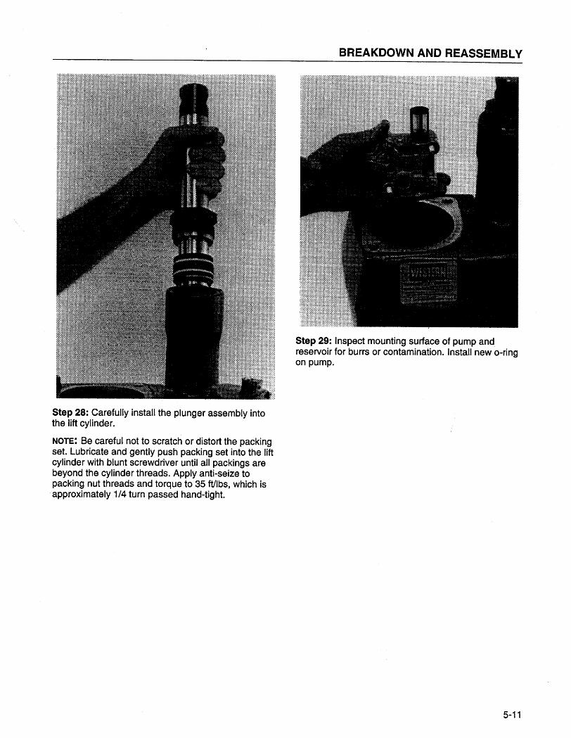
Step 28: Carefully install the plunger assembly intothe lift cylinder.
NOTE: Be careful not to scratch or distort the packingset. Lubricate and gently push packing set into the liftcylinder with blunt screwdriver until all packings arebeyond the cylinder threads. Apply anti-seize topacking nut threads and torque to 35 ftlbs, which isapproximately 1/4 turn passed hand-tight.
Step 29: Inspect mounting surface of pump andreservoir for burrs or contamination. Install new o-ringon pump.
5-11
ISARMATIC(B Mark Ilia · Cable
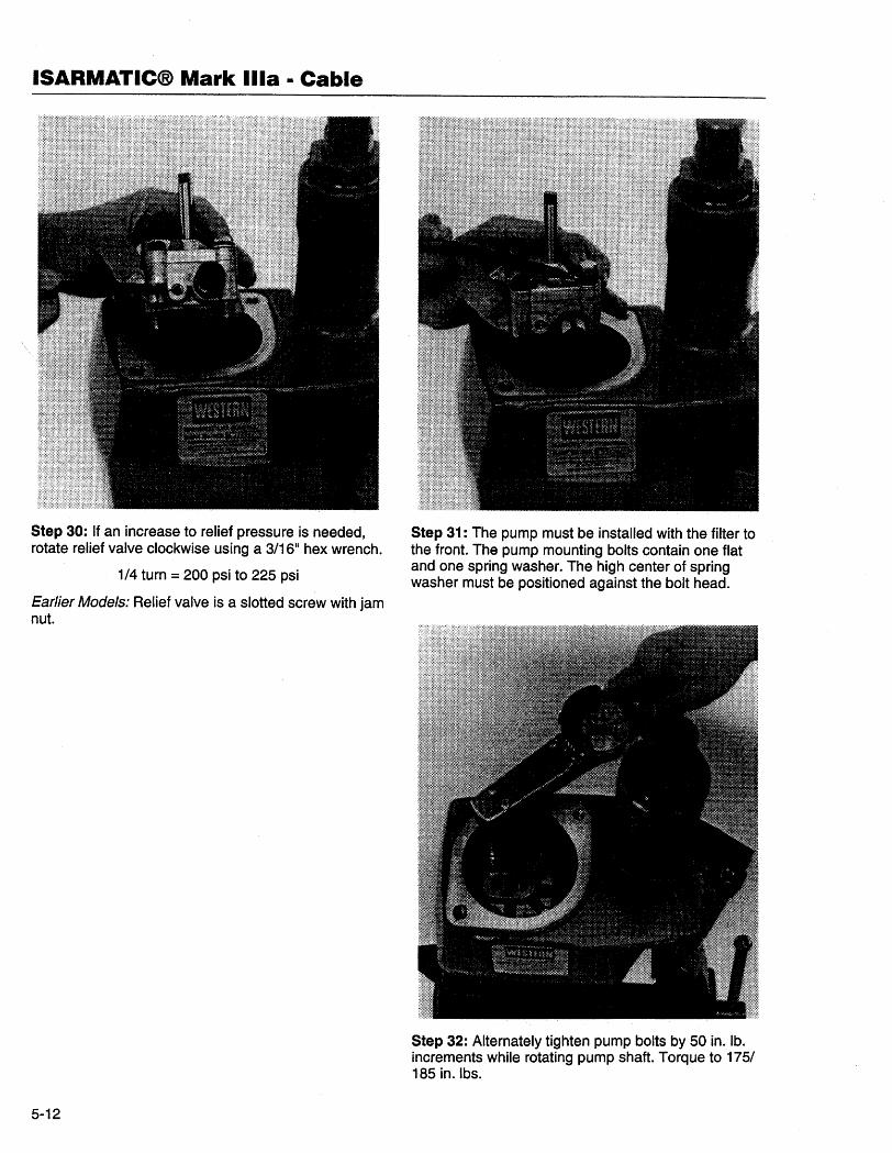
Step 30: If an increase to relief pressure is needed,rotate relief valve clockwise using a 3/16" hex wrench.
1/4 turn = 200 psi to 225 psi
Earlier Models: Relief valve is a slotted screw with jamnut.
5-12
Step 31: The pump must be installed with the filter tothe front. The pump mounting bolts contain one flatand one spring washer. The high center of springwasher must be positioned against the bolt head.
Step 32: Alternately tighten pump bolts by 50 in. lb.increments while rotating pump shaft. Torque to 175/1B5 in. Ibs.
BREAKDOWN AND REASSEMBLY
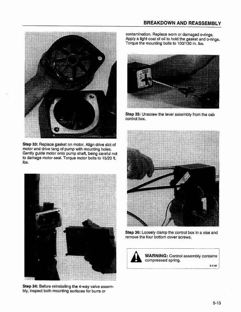
Step 33: Replace gasket on motor. Align drive slot ofmotor and drive tang of pump with mounting holes.Gently guide motor onto pump shaft, being careful notto damage motor seaL. Torque motor bolts to 15/20 ft.Ibs.
Step 34: Before reinstalling the 4-way valve assem-bly, inspect both mounting surfaces for burrs or
contamination. Replace worn or damaged o-rings.Apply a light coat of oil to hold the gasket and o-rings.Torque the mounting bolts to 100/130 in. Ibs.
Step 35: Unscrew the lever assembly from the cabcontrol box.
Step 36: Loosely clamp the control box in a vise andremove the four bottom cover screws.
I It WARNING: Control assembly contains Ia compressed spring. I
S 5.36
5-13
ISARMATIC(B Mark Ilia · Cable
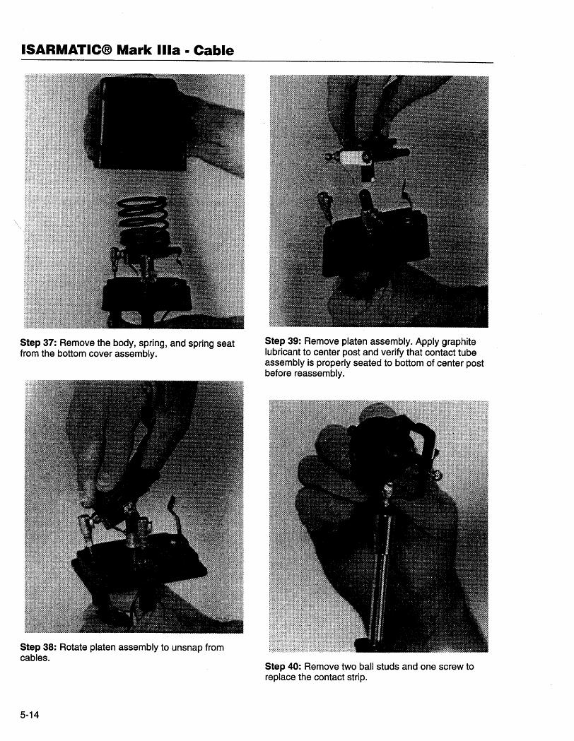
Step 37: Remove the body, spring, and spring seatfrom the bottom cover assembly.
Step 38: Rotate platen assembly to unsnap fromcables.
5-14
Step 39: Remove platen assembly. Apply graphitelubricant to center post and verify that contact tubeassembly is properly seated to bottom of center postbefore reassembly.
Step 40: Remove two ball studs and one screw toreplace the contact strip.
BREAKDOWN AND REASSEMBLY
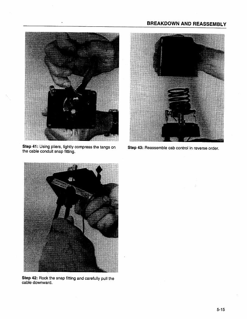
Step 41: Using pliers, lightly compress the tangs onthe cable conduit snap fitting.
Step 42: Rock the snap fitting and carefully pull thecable downward.
Step 43: Reassemble cab control in reverse order.
5-15
ISARMATIC(B Mark Ilia · Cable
5-16