FloStat Hydraulic System - Western...
70
July 15, 2017 Lit. No. 72103, Rev. 01 MECHANIC'S GUIDE UTV V-Plow Featuring the FloStat ® Hydraulic System CAUTION Read this manual before servicing the snowplow. SNOWPLOWS
Transcript of FloStat Hydraulic System - Western...

July 15, 2017Lit. No. 72103, Rev. 01
MECHANIC'S GUIDE
UTV V-PlowFeaturing the
FloStat® Hydraulic System
CAUTIONRead this manual before servicing the snowplow.
SNOWPLOWS


Lit. No. 72103, Rev. 01 July 15, 2017
TABLE OF CONTENTS
INTRODUCTION ................................................................................................4Recommended Tools ...................................................................................4Available Service Items ...............................................................................4
SAFETY INFORMATION ...................................................................................5Torque Chart ................................................................................................7
BLADE, T‑FRAME & HEADGEAR ...................................................................8T‑Frame to Blade Assembly ........................................................................8Center Deflector, Blade Guides, and Stand .................................................9Using the Blade Spring Replacement Tool ................................................10
HYDRAULIC SYSTEM ....................................................................................11FloStat® Hydraulic System Specifications .................................................11Hydraulic Unit Components .......................................................................12Valve Location ...........................................................................................13Cartridge Valves ........................................................................................14Check Valves .............................................................................................15Relief Valves ..............................................................................................15Hydraulic Fitting and Hose Installation ......................................................16Ram Seal Installation .................................................................................17Cartridge and Check Valve Removal .........................................................18Blade Drop speed Adjustment ...................................................................18
VEHICLE‑SIDE ELECTRICAL COMPONENTS .............................................19Harness Diagram .......................................................................................19
CONTROLS – FLEET FLEX ELECTRICAL SYSTEM ................................... 20Overview ................................................................................................... 20Operating the CabCommand® Hand‑Held Control ....................................21Operating the Joystick Control .................................................................. 23
FLEET FLEX ELECTRICAL SYSTEM ............................................................25Smooth Stop and One‑Touch Float Features ............................................25SECURITY GUARD™ Snowplow Anti-Theft System ............................... 26
ELECTRICAL & HYDRAULIC SCHEMATICS ............................................... 29Legend – Electrical & Hydraulic Symbols ................................................. 29Electrical Schematic – UTV V‑Plow.......................................................... 30Hydraulic Schematic – UTV V‑Plow ..........................................................31Raise ..........................................................................................................32Lower/Float ............................................................................................... 34Angle Right .............................................................................................. 36Angle Left ................................................................................................. 38Retract (Vee) ............................................................................................. 40Scoop .........................................................................................................42Right (PS) Wing Extend ............................................................................ 44Right (PS) Wing Retract ............................................................................ 46Left (DS) Wing Extend .............................................................................. 48Left (DS) Wing Retract .............................................................................. 50Hold in Raise Position ...............................................................................52Striking an Object While Plowing Forward ............................................... 53Striking an Object While Back Dragging ................................................... 54
TROUBLESHOOTING GUIDE ....................................................................... 55How to Use the Troubleshooting Guide .................................................... 56Electrical Testing ....................................................................................... 56Fuse Replacement .................................................................................... 56Before You Begin .......................................................................................57Solenoid Coil Activation Test (SCAT) ........................................................ 58Individual Solenoid Coil Test ......................................................................61Control/Cable/Plow Module Test ...............................................................62Motor and Motor Relay Test ...................................................................... 63Pump Pressure Test ................................................................................. 64Relief Valve Inspection and Adjustment ................................................... 65Scrape Lock Adjustment ........................................................................... 66Replacing Damaged Bearing Sleeves ...................................................... 68

Lit. No. 72103, Rev. 01 July 15, 2017
4
This guide has been prepared to assist the trained mechanic in the service of WESTERN® IMPACT™ UTV V‑plows. It also provides safety information and recommendations. We urge all mechanics to read the safety statements and instructions in this manual carefully before attempting to service the snowplow equipment covered by this guide.
Service of your WESTERN snowplow equipment is best performed by your local Western Products dealer. They know your snowplow best and are interested in your complete satisfaction.
INTRODUCTION
RECOMMENDED TOOLS
• Long/slender needle‑nose pliers• Flat screwdriver• 12 V test light• Torque wrench• Allen wrench set, including 3/8" Allen wrench• Combination standard wrench set• 1/4" drive ratchet set with 6" extension• 3/8" drive ratchet set• Deep socket: 7/8"• Digital volt /ohmmeter• Ammeter• Pressure test kit• Flashlight• Pick set• Hammer• Pencil magnet• Mini fuses: 5 A and 2 A• Vacuum pump with 3/8" NPT barbed fitting• 3/8" NPT plug
TORX® is a registered (®) trademark of Textron, Inc.
AVAILABLE SERVICE ITEMS
• Motor Bearing Sleeve Repair Kit, PN 64589 (Requires 3/8-24 x 4 hex cap screw, not included.)
• Pressure Test Kit, PN 56679 (Requires adapter fitting, not included.)
• Spring Replacement Tool: PN 20043‑1• Diagnostic Harness, PN 29290-2
• Pump Shaft Seal Repair Kit, PN 28856 (Requires 1/4-28 x 4-1/2 hex cap screw, not included.)

Lit. No. 72103, Rev. 01 July 15, 2017
5NOTE: Indicates a situation or action that can lead to damage to your snowplow and vehicle or other property. Other useful information can also be described.
SAFETY INFORMATION
WARNING/CAUTION AND INSTRUCTION LABELS
Become familiar with and inform users about the warning and instruction labels on the back of the blade.
NOTE: If labels are missing or cannot be read, see your local WESTERN® dealer.
CAUTIONIndicates a potentially hazardous situation that, if not avoided, may result in minor or moderate injury. It may also be used to alert against unsafe practices.
WARNINGIndicates a potentially hazardous situation that, if not avoided, could result in death or serious personal injury.
SAFETY DEFINITIONS
Warning/Caution Label
Instruction Label

Lit. No. 72103, Rev. 01 July 15, 2017
6
SAFETY INFORMATION
SAFETY PRECAUTIONS
Improper installation and operation could cause personal injury, and/or equipment and property damage. Read and understand labels and the Owner's Manual before installing, operating, or making adjustments.
HYDRAULIC SAFETY
• Always inspect hydraulic components and hoses before using. Replace any damaged or worn parts immediately.
• If you suspect a hose leak, DO NOT use your hand to locate it. Use a piece of cardboard or wood.
WARNINGLower the blade when vehicle is parked. Temperature changes could change hydraulic pressure, causing the blade to drop unexpectedly or damaging hydraulic components. Failure to do this could result in serious personal injury.
WARNINGRemove blade assembly before placing vehicle on hoist.
WARNINGThe driver shall keep bystanders clear of the blade when it is being raised, lowered, or angled. Do not stand between vehicle and blade or within 8 feet of a moving blade. A moving or falling blade could cause personal injury.
WARNINGDo not exceed GVWR or GAWR including blade and ballast. The rating label is found on driver‑side vehicle door cornerpost.
WARNINGTo prevent accidental movement of the blade, always turn the control OFF whenever the snowplow is not in use. The power indicator light will turn OFF.
WARNINGKeep hands and feet clear of the blade and T‑frame when mounting or removing the snowplow. Moving or falling assemblies could cause personal injury.
CAUTIONRefer to the current online selection system for minimum vehicle recommendations and ballast requirements.
WARNINGHydraulic fluid under pressure can cause skin injection injury. If you are injured by hydraulic fluid, get medical attention immediately.
FUSES
The electrical and hydraulic systems contain several blade‑style automotive fuses. If a problem should occur and fuse replacement is necessary, the replacement fuse must be of the same type and amperage rating as the original. Installing a fuse with a higher rating can damage the system and could start a fire. See the Troubleshooting section of this manual for fuse replacement information.
PERSONAL SAFETY
• Remove ignition key and put the vehicle in park or in gear to prevent others from starting the vehicle during installation or service.
• Wear only snug-fitting clothing while working on your vehicle or snowplow.
• Do not wear jewelry or a necktie, and secure long hair.
• Wear safety goggles to protect your eyes from battery acid, gasoline, dirt, and dust.
• Avoid touching hot surfaces such as the engine, radiator, hoses, and exhaust pipes.
• Always have a fire extinguisher rated BC handy, for flammable liquids and electrical fires.

Lit. No. 72103, Rev. 01 July 15, 2017
7
TORQUE CHARTBATTERY SAFETY
NOISE
Airborne noise emission during use is below 70 dB(A) for the snowplow operator.
VIBRATION
Operating snowplow vibration does not exceed 2.5 m/s2 to the hand‑arm or 0.5 m/s2 to the whole body.
FIRE AND EXPLOSION
Be careful when using gasoline. Do not use gasoline to clean parts. Store only in approved containers away from sources of heat or flame.
CELL PHONES
A driver's first responsibility is the safe operation of the vehicle. The most important thing you can do to prevent a crash is to avoid distractions and pay attention to the road. Wait until it is safe to operate Mobile Communication Equipment such as cell phones, text messaging devices, pagers, or two‑way radios.
VENTILATION
SAFETY INFORMATION
1/4-20 109 1541/4-28 121 1715/16-18 150 2125/16-24 170 2403/8-16 269 3763/8-24 297 4207/16-14 429 6067/16-20
9/16-129/16-185/8-115/8-183/4-103/4-167/8-97/8-14 474 669
644 9091-81-12 704 995
1/2-131/2-20
11.913.724.627.343.6
26.953.393148
49.469.877.9
106.4120.0
8.49.717.419.230.835.049.455.275.385.0
M6 x 1.00
M12 x 1.75
M8 x 1.25
M14 x 2.00
M10 x 1.50M27 x 3.00
M22 x 2.50
M30 x 3.50
M24 x 3.00
M20 x 2.5011.119.538.567107
7.761377811391545
4504285627961117
M33 x 3.50M36 x 4.00
21012701
14681952
325
M16 x 2.00 231167M18 x 2.50 318222
Recommended Fastener Torque Chart
Size SizeTorque (ft-lb)
Grade5
Grade8
Metric Fasteners Class 8.8 and 10.9
These torque values apply to fastenersexcept those noted in the instructions.
Torque (ft-lb)Grade
5Grade
8
Size SizeTorque (ft-lb)
Class8.8
Class10.9
Torque (ft-lb)Class
8.8Class10.9
Inch Fasteners Grade 5 and Grade 8
CAUTIONBatteries normally produce explosive gases, which can cause personal injury. Therefore, do not allow flames, sparks, or lit tobacco to come near the battery. When charging or working near a battery, always cover your face and protect your eyes, and also provide ventilation.• Batteries contain sulfuric acid, which
burns skin, eyes, and clothing.• Disconnect the battery before removing
or replacing any electrical components.
CAUTIONRead instructions before assembling. Fasteners should be finger tight until instructed to tighten according to torque chart. Use standard methods and practices when attaching snowplow, including proper personal protective safety equipment.
WARNINGGasoline is highly flammable and gasoline vapor is explosive. Never smoke while working on vehicle. Keep all open flames away from gasoline tank and lines. Wipe up any spilled gasoline immediately.
WARNINGVehicle exhaust contains lethal fumes. Breathing these fumes, even in low concentrations, can cause death. Never operate a vehicle in an enclosed area without venting exhaust to the outside.

Lit. No. 72103, Rev. 01 July 15, 2017
8
BLADE, T‑FRAME & HEADGEAR
T‑FRAME TO BLADE ASSEMBLY
1. Align the hinges of the blade wings. Position the T‑frame assembly between the wings so the holes in the T‑frame are aligned with the holes in wing hinges.
2. Insert the pivot pin from top to bottom through all hinges as shown.
3. Move the snowplow into a normal operating position.
Based on Installation Instructions for UTV V-Plow (Lit. No. 78520/75821/78522, Rev. 00).
Pivot Pin
1/2" x 3-7/16"Clevis Pin
5/32" x 1-1/2"Cotter PinAngle Ram
4. The width of the UTV determines whether to use the inside or outside angle ram holes on the back of the blade. The snowplow width in the retracted (vee) position is to be equal to or greater than the width of the UTV. If the UTV width exceeds 60", the angle rams will be attached at the outside holes on the back of the blade. If the UTV is less than 60" wide, the rams will be attached at the inside holes.
*Your snowplow may use 1/2" x 4" cap screws for the angle ram pins. Service kit contains a 1/2" x 3-7/16" clevis pin as the replacement part.
Inside Holes = 60" Blade Width in Vee Position
Outside Holes = 66" Blade Width in Vee Position
5. Align the holes in the rod end of the angle ram with the selected holes on the back of the blade. Install a 1/2" x 3-7/16" clevis pin* from the top down to attach each rod and secure with 5/32" x 1-1/2" cotter pins.
Lit. No. 72103, Rev. 01 July 15, 2017
9
BLADE, T‑FRAME & HEADGEAR
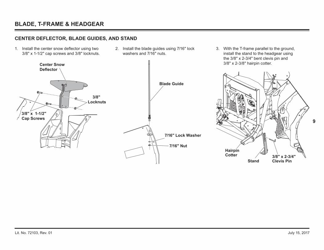
Center Snow Deflector
3/8" x 1-1/2" Cap Screws
3/8" Locknuts
Blade Guide
7/16" Lock Washer
7/16" Nut
1. Install the center snow deflector using two 3/8" x 1-1/2" cap screws and 3/8" locknuts.
2. Install the blade guides using 7/16" lock washers and 7/16" nuts.
3. With the T-frame parallel to the ground, install the stand to the headgear using the 3/8" x 2-3/4" bent clevis pin and 3/8" x 2-3/8" hairpin cotter.
HairpinCotter
Stand3/8" x 2-3/4"Clevis Pin
CENTER DEFLECTOR, BLADE GUIDES, AND STAND

Lit. No. 72103, Rev. 01 July 15, 2017
10
BLADE, T‑FRAME & HEADGEAR
USING THE BLADE SPRING REPLACEMENT TOOL
1. Park the vehicle on a smooth, level, hard surface, such as concrete. Lower the blade to the ground and turn the control OFF. Disconnect the snowplow from the vehicle or turn the vehicle ignition to the OFF position and remove the key.
2. The spring replacement tool (PN 20043‑1) ships fully assembled. Before using the tool, apply a light coating of multipurpose grease to the threaded end of the spade bolt.
3. Place the tool on the top anchor above the spring, making sure the upper end of the spring bar is between the clevis tabs of the spring replacement tool. Insert a 1/2" x 2" cap screw through the lower hole in one clevis tab, through the top hole in the spring bar, then the hole in the other clevis tab. Install a 1/2" nut and hand tighten.
1/2" x 2" cap screw inserted through clevis and spring bar.
Spring Bar
Top Anchor
1/4" x 1-1/4" Pin
5/8" Nut
4. Use hand tools to tighten the 5/8" hex nut until the spring bar is raised enough to access the pin hole. Insert the 1/4" x 1-1/4" pin through the pin hole, centering the pin from side to side.
5. Loosen the 5/8" hex nut to lower the spring bar. Remove the spring tool assembly by removing the 1/2" cap screw inserted through the spring bar in Step 3.
6. Detach the spring from the blade by removing the shoulder bolt and locknut at the bottom of the spring bar. Retain the fasteners.
7. Insert the replacement spring with spring bar up through the top anchor on the blade. Install the bottom of the spring bar to the anchor on the trip edge using the retained shoulder bolt and locknut. Tighten to 50 ft‑lb.
8. Repeat Step 3.
9. Use hand tools to tighten the 5/8" nut until the spring bar is raised enough to access the 1/4" x 1-1/4" pin inserted in Step 4. Remove the pin.
10. Repeat Step 5.
Frame
Clevis
Grease spade bolt threads.

Lit. No. 72103, Rev. 01 July 15, 2017
11
Hydraulic Fluid
Use WESTERN® Hydraulic Fluid to –40°F (–40°C) or other fluid conforming to military specification MIL-H-5606 A, such as Mobil Aero HFA or Shell AeroShell® Fluid 4. Use of products other than these recommended fluids may cause poor hydraulic system performance and damage to internal components.
The FloStat hydraulic system delivers fast and uniform speed for blade movement, raising the blade in two seconds and performing all angling functions in less than five seconds.
Relief Valve Settings
• Pump Relief Valve (1): 2000 ± 100 psi 2 turns CCW from fully seated
• Base‑End Relief Valves (2): 3000 psi 1‑3/8 turns CCW from fully seated
• Rod‑End Relief Valves (2): 1150 psi 2‑5/8 turns CCW from fully seated
• Scrape Lock Relief Valve (1): 210 psi 1‑3/4 turns CCW from fully seated
Pump Motor
12 V DC with +/– Connection3.0" dia. 2.8 kW Motor (1.39 hp)2000 ± 100 psi Pump Relief Valve3000 psi Plowing Relief Valve1150 psi Back‑Dragging Relief Valve210 psi Scrape Lock0.000476 gal/rev PumpHydraulic Hose 1/4 SAE 100R1
System Capacity
• Unit reservoir: 1‑3/4 quarts• System total: 2‑1/8 quarts
HYDRAULIC SYSTEM
CAUTIONDo not mix different types of hydraulic fluid. Some fluids are not compatible and may cause performance problems and product damage.
AeroShell® is a registered (®) trademark of Shell Oil Company.
FloStat® HYDRAULIC SYSTEM SPECIFICATIONS
Electrical System (Approximate Values)
• Solenoid Coil Resistance = 7 ohm @ room temp.• Solenoid Coil Ampere Draw = 1.5 A• Motor Relay Coil Resistance = 5.4 ohm• Motor Relay Ampere Draw = 3.0 A• Maximum Motor Ampere Draw = 190 A over
relief at 2000 psi• Switch Accessory Lead Draw = 0.75 A
Fuses
• Vehicle Control Harness Fuse: 2 A mini• Hydraulic Unit Harness Fuses: 5 A mini
Fastener Torque SpecificationsPump Cap Screws 5/16‑18 x 2‑1/2 150–160 in‑lbMotor Terminals (+ and –) 5/16‑18 Nut 50–60 in‑lbMotor to Manifold Cap Screws M5 x.8 Bolt 30–40 in‑lbReservoir Screws #10‑24 x 5/16 30–35 in‑lbSolenoid Valves 7/8 Hex Head 19–21 ft‑lbCoil Nuts 3/4 Hex‑Head Jam Nut 40–60 in‑lbCover Screws 1/4‑20 x 1/2 Shoulder Screw 60–80 in‑lbSAE O‑Ring Plugs 1/8 or 5/32 Internal Hex 55–65 in‑lbHydraulic Unit Mount Bolts 3/8‑16 x 1 25–33 ft‑lbCheck Valves 7/8 Hex Head 19–21 ft‑lbSecondary to Primary Manifolds 1/4‑20 x 3 10–13 ft‑lbMotor Relay Small Terminals 10‑32 Nut 15 in‑lb maxMotor Relay Large Terminals 5/16‑24 Nut 35 in‑lb maxMotor Relay Mount Screws 1/4‑20 x 1/4 50–70 in‑lbPlow Module Mount Screws 1/4‑20 x 5/8 60–70 in‑lbAngle Ram Piston Locknuts 90–100 ft‑lbLift Ram Piston Nut 30–40 ft‑lbAngle & Lift Rams Gland Nuts 120–150 ft‑lb

Lit. No. 72103, Rev. 01 July 15, 2017
12
HYDRAULIC UNIT COMPONENTS
Breather/Fill Plug
Reservoir
Drain Plug
Pump
Pump ShaftSeal
Filter
QuillSolenoid Cartridge Valve
3-Position Solenoid Cartridge Valve
Coil Spacer
Bushing
O-Ring O-Ring
Magnet
Motor
O-Ring
Check Valve
Primary Manifold
Secondary Manifold
Relief Valve
Relief Valve
Pilot-Operated Check Valve Check Valve
Scrape Lock Relief Valve
Coil
Coil
3-Position Solenoid Cartridge Valve
Check Valve
HYDRAULIC SYSTEM

Lit. No. 72103, Rev. 01 July 15, 2017
13
VALVE LOCATION
HYDRAULIC SYSTEM
S1
S4C2
Quill
S2
CV3
S4C1PC1
S3C2
S5
CV4
CV5
PC2
S3C1
CV2
RV1
RV5
RV3
Lift RamBase
Lift Ram Rod
CV1RV6
RV2
RV4
PS Base EndDS Base End
PS Rod End
DS Rod End
Pressure Test Port
Solenoid Cartridge ValvesCoil Valve Type Wire ColorS1 SV08‑2211 BlueS2 SV10‑43 Dark Green
S3C1 SV08‑47C BrownS3C2 SV08‑47C WhiteS4C1 SV08‑47C PurpleS4C2 SV08‑47C Orange
S5 SVCV08‑20 Yellow

Lit. No. 72103, Rev. 01 July 15, 2017
14
HYDRAULIC SYSTEM
Blade Movement
Solenoid
Motor M ON ON ON ON ON ON ON ON ONSV08‑2211 S1 ONSV10‑43 S2 ON ON
SV08‑47CS3C1 ON ON ONS3C2 ON
SV08‑47CS4C1 ON ON ONS4C2 ON ON ON
SVCV08‑20 S5 ON
VEE SCOOP EXTENDLEFTANGLE
LEFTANGLERIGHTRAISE LOWER
RIGHTRETRACT
RIGHTEXTEND
LEFTRETRACT
CARTRIDGE VALVES
The UTV V‑Plow hydraulic system performs ten blade movement functions.
All functions require the vehicle ignition (key) switch to be in the "RUN" or "ACCESSORY" position and the power to be activated on the snowplow cab control.
Nine of the ten hydraulic functions require energizing the electric motor and opening solenoid cartridge valves. The LOWER function does not energize the motor but requires the opening of one cartridge valve.
Power from the vehicle battery is supplied to the solenoid coils and the motor relay via the plow module. The solenoid cartridge valves operate in various combinations, directed by the cab control, to send hydraulic fluid to the snowplow lift and angle rams or back to the reservoir. (Power is supplied to the plow module via the battery cable and motor relay connection.)

Lit. No. 72103, Rev. 01 July 15, 2017
15
HYDRAULIC SYSTEM
CHECK VALVES
The check valves supply make-up fluid to the low‑pressure side of a ram that is extending or retracting through a relief valve due to impact on one or both wings.
A pilot-operated check valve (PC) allows fluid to flow in only one direction unless it receives pilot pressure through another circuit to shift it to an open position.
Tighten check valves to 19–21 ft‑lb.
Check ValvesCV1
CV08‑2004CV2CV3CV4CV5 CV08‑2059PC1
PC08‑30PC2
RELIEF VALVES
When all cartridge valves are closed, hydraulic fluid is trapped in the ram by the solenoid cartridge valves, check valves, base-end relief valves, and rod‑end relief valves.
When the snowplow contacts an object while plowing, force of the impact increases hydraulic pressure in the base end of the ram. When pressure exceeds 3000 psi, the ram's base-end relief valves open, allowing hydraulic fluid back to the reservoir. Due to the small volume on the rod side of the piston, fluid is not replaced. This causes a slight temporary vacuum in that circuit.
When the snowplow contacts an object while back dragging, force of the impact increases hydraulic pressure in the rod end of the ram. When pressure exceeds 1500 psi, the ram's rod-end relief valve opens, allowing hydraulic fluid into the reservoir passage. The base-end check valve allows fluid to fill the base end of the ram. Because of differential area on either side of the ram's piston, fluid flows from the reservoir to the base end.
NOTE: Relief valve RV2 and components are not interchangeable with RV1, RV3, RV4, RV5, or RV6. See "Relief Valve Inspection and Adjustment" in the Troubleshooting section for service.
NOTE: See "Striking an Object While Plowing" Schematics for Details.
Primary Manifold
PC1PC2
CV1
CV2
CV3CV4
CV5
Secondary Manifold
Primary Manifold
Secondary Manifold
RV1
RV2
RV3
Pressure Test Port
RV4RV5
RV6
Relief Valve SettingsRV1 Pump 2000 ± 100 psi
RV2 Lift Ram Base End (Scrape Lock) 210 psi
RV3 DS Ram Rod End1150 ± 100 psi
RV4 PS Ram Rod EndRV5 DS Ram Base End
3000 ± 100 psiRV6 PS Ram Base End

Lit. No. 72103, Rev. 01 July 15, 2017
16
HYDRAULIC SYSTEM
NOTE: Overtightening JIC hose fitting ends will result in a fractured fitting.
DO NOT use thread sealant/tape on hydraulic hoses or fittings. These materials could damage the product. Always use two wrenches to ensure proper tightening of fittings and hoses.
To install SAE O-ring fittings in the valve block and rams:
1. Turn the jam nut on the fitting as far back as possible.
2. Lubricate the O-ring with clean hydraulic fluid.
3. Screw the fitting into the port by hand until the washer contacts the port face and the shoulder of the jam nut threads.
4. Unscrew the fitting to its proper position; no more than one full turn.
5. Using two wrenches, hold the fitting body in position and tighten the jam nut until the washer again contacts port face, then tighten an additional 1/8 to 1/4 turn to lock the fitting in place. Final torque on the jam nut should be approximately 20 ft‑lb.
To install hydraulic hoses:
1. Screw the flare nut onto the fitting flare and hand tighten it.
2. Align the hose so there are no twists or sharp bends and so it will not be pinched or pulled by moving parts.
3. Using a pair of adjustable pliers, hold the hose in position, and use a wrench to tighten the flare nut 1/8 to 1/4 turn beyond hand tight. Final torque on the flare nut should be approximately 20 ft‑lb.
HYDRAULIC FITTING AND HOSE INSTALLATION
To DS Ram Base End
To DS Ram Rod End
To PS Ram Rod End
To PS Ram Base End
To Lift RamBase (Upper) To Lift Ram
Rod (Lower)
Angle Ram
90º Elbow
90º Elbow
45º Elbow
90º Elbow,Extra Long
Lift Ram
4. Reinstall any protective hose wraps in their original positions.

Lit. No. 72103, Rev. 01 July 15, 2017
17
RAM SEAL INSTALLATION
1. Lubricate the O-rings with hydraulic fluid before assembly.
2. Assemble the gland components as shown, then lubricate them with hydraulic fluid.
3. Remove the piston from the rod and assemble the piston components as shown.
4. Assemble the gland to threaded end of the rod. Do not slide the gland over the cross hole in the rod.
5. Reassemble piston to rod and tighten the nut:• 90–100 ft‑lb for angle ram• 0–40 ft‑lb for lift ram.
6. Assemble the O‑ring into the groove on the rod. Use tape or other protection on the threads.
7. Apply a bead of medium‑strength threadlocker all around the threads of the gland.
8. Lubricate the piston seals and the inside of the cylinder.
9. Press the rod assembly into the cylinder and tighten the gland nut to 120–150 ft‑lb.
HYDRAULIC SYSTEM
Nut
Groovein Rod
Rod
Gland
Piston
Cylinder
Seal Position
Gland
Back-Up Ring
Wiper
Seal O-RingWear Ring Inner
Backing Ring
Outer Seal
Wear Ring
Gland Section Piston Section
Lit. No. 72103, Rev. 01 July 15, 2017
18
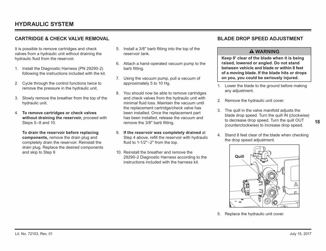
1. Lower the blade to the ground before making any adjustment.
2. Remove the hydraulic unit cover.
3. The quill in the valve manifold adjusts the blade drop speed. Turn the quill IN (clockwise) to decrease drop speed. Turn the quill OUT (counterclockwise) to increase drop speed.
4. Stand 8 feet clear of the blade when checking the drop speed adjustment.
5. Replace the hydraulic unit cover.
CARTRIDGE & CHECK VALVE REMOVAL BLADE DROP SPEED ADJUSTMENT
HYDRAULIC SYSTEM
It is possible to remove cartridges and check valves from a hydraulic unit without draining the hydraulic fluid from the reservoir.
1. Install the Diagnostic Harness (PN 29290‑2) following the instructions included with the kit.
2. Cycle through the control functions twice to remove the pressure in the hydraulic unit.
3. Slowly remove the breather from the top of the hydraulic unit.
4. To remove cartridges or check valves without draining the reservoir, proceed with Steps 5–8 and 10. To drain the reservoir before replacing components, remove the drain plug and completely drain the reservoir. Reinstall the drain plug. Replace the desired components and skip to Step 9
WARNINGKeep 8' clear of the blade when it is being raised, lowered or angled. Do not stand between vehicle and blade or within 8 feet of a moving blade. If the blade hits or drops on you, you could be seriously injured.
Quill
5. Install a 3/8" barb fitting into the top of the reservoir tank.
6. Attach a hand‑operated vacuum pump to the barb fitting.
7. Using the vacuum pump, pull a vacuum of approximately 5 to 10 Hg.
8. You should now be able to remove cartridges and check valves from the hydraulic unit with minimal fluid loss. Maintain the vacuum until the replacement cartridge/check valve has been installed. Once the replacement part has been installed, release the vacuum and remove the 3/8" barb fitting.
9. If the reservoir was completely drained at Step 4 above, refill the reservoir with hydraulic fluid to 1-1/2"–2" from the top.
10. Reinstall the breather and remove the 29290‑2 Diagnostic Harness according to the instructions included with the harness kit.

Lit. No. 72103, Rev. 01 July 15, 2017
19
VEHICLE‑SIDE ELECTRICAL COMPONENTS
HARNESS DIAGRAM
Battery
Vehicle Control Harness
Vehicle Battery Cable
To Snowplow Control
To SwitchedAccessory
BAT
2 Amp Fuse
RED
BLK
12
RED
CAUTIONOn 2‑plug electrical systems, plug covers shall be used whenever snowplow is disconnected. Vehicle Battery Cable is 12 V unfused source.

Lit. No. 72103, Rev. 01 July 15, 2017
20
CONTROLS
The snowplow can be operated by a hand‑held control or by a joystick‑style control.
Each control is equipped with an ON/OFF button or switch and an indicator light to show when the control is powered ON or OFF. The controls are powered by the vehicle's battery, so the vehicle ignition (key) switch must be ON to use the controls.
The ON/OFF button or switch on the cab control allows you to turn OFF the control and prevent blade movement even when the vehicle ignition switch is ON.
WARNINGTo prevent accidental movement of the blade, always turn the control OFF whenever the snowplow is not in use. The power indicator light will turn OFF.
Power IndicatorLight (red)
ON/OFF Button(Emergency Stop)
ON/OFF Switch(Emergency Stop)on side of control
Hand-Held Control
Joystick Control
The control ON/OFF button or switch serves as an emergency stop, if required.
All controls are protected by a replaceable fuse located in the control harness assembly. See "Fuse Replacement" in the Maintenance section of the Owner's Manual.
FLEET FLEX electrical system controls are able to sense a lack of communication with the electrical system. Should the indicator light start to flash, refer to "Control/Cable/Plow Module Test" in the Troubleshooting section of this manual.
OVERVIEW

Lit. No. 72103, Rev. 01 July 15, 2017
21
Control Functions
Raise, Lower, Float, Angle
Pressing the four diamond‑shaped buttons in the center of the control face will result in the blade movements described in the table.
Function Description of Operation
RAISEPress this button to raise the blade and cancel the FLOAT mode. Function times out after 4.0 seconds.
LOWERPress this button to lower the blade. Release the button to stop the blade at the desired height.
FLOAT*
Press the LOWER button and hold 3/4 second to activate this mode. The FLOAT light in the upper left corner of the control face will illuminate. The blade will lower to the ground surface and follow the contour of the surface as it dips or raises. Function does not time out; however, control will shut down after 20 minutes of nonuse.Press the RAISE button momentarily to cancel FLOAT. Angling left or right will not interrupt (pause) the FLOAT function.
Function Time‑Outs
All control functions, except LOWER/FLOAT, time out (stop) automatically after a period of time. This is to limit the amount of electrical energy required from the vehicle.
NOTE: If a control function times out before the desired blade movement is complete, release the button and press it again.
Automatic Shutdown
The control will automatically turn OFF after being idle for 20 minutes. To reactivate the control after a shutdown, press the ON/OFF button.
Smooth Stop
The control automatically allows the blade to coast to a stop when a control button is released. This results in smoother operation, reduces the shock to the hydraulic system, and increases hose and valve life. For instructions on enabling/disabling this feature, see "Smooth Stop" in this section.
CONTROLS
OPERATING THE CabCommand HAND‑HELD CONTROL
RAISE
LOWER
RL
ON/OFFFLOAT
1
3
2
4
S C O
OP
RE
T
R A C T
W
INGW I N G
FLOAT Light(green)
WARNINGThe driver shall keep bystanders clear of the blade when it is being raised, lowered, or angled. Do not stand between vehicle and blade or within 8 feet of a moving blade. A moving or falling blade could cause personal injury.
1. Turn the vehicle ignition switch to the "ON" or "ACCESSORY" position.
2. Press the ON/OFF button on the control. The power indicator light glows red, indicating that the control is ON. The power indicator light glows red whenever the control and vehicle ignition switch are both ON, and the electrical connections to the snowplow are completed.
The ON/OFF button operates as an emergency stop, if required.
The round buttons numbered 1, 2, 3, and 4 operate the SECURITY GUARD™ system. See the SECURITY GUARD System section of this guide for instructions.
Based on Operating Instructions for 85200 & 96500 CabCommand Hand-Held Control (Lit. No. 96582, Rev. 00). Table continues on next page.
RAISE
LOWER
RL
ON/OFFFLOAT
1
3
2
4
S C O
OP
RE
T
R A C T
W
INGW I N G
Buttons 1, 2, 3, and 4 control SECURITY GUARD system functions.

Lit. No. 72103, Rev. 01 July 15, 2017
22
L (Angle Left)
With wings in a straight line, press the L button to move both wings to the angle left position. The left wing retracts while the right wing extends. Function times out after 3.0 seconds.
R (Angle Right)
With wings in a straight line, press the R button to move both wings to the angle right position. The right wing retracts while the left wing extends. Function times out after 3.0 seconds.
* FLOAT mode activates immediately when the One‑Touch FLOAT feature is enabled. See the One‑Touch FLOAT section for more information.
Scoop/Retract Blade Positions
The two round buttons located to the left and right of the RAISE button move both wings at the same time, into the following blade positions.
Function Description of Operation
SCOOPPress this button to extend both wings forward into the scoop position. Function times out after 5.0 seconds.
RETRACTPress this button to draw both wings into the fully retracted/vee position. Function times out after 3.0 seconds.
Wing Positions
The two round buttons located to the left and right of the LOWER button move either wing independently of the other, as described below.
Function Description of Operation
L WING
Press this button on the left side of the control to move the left wing. The first time the button is pressed after the control is turned ON or another function is used, the wing will extend. Repeated use of the same button, without using another function, results in movement in the opposite direction from the previous movement. Function times out after 3.0 seconds.
R WING
Press this button on the right side of the control to move the right wing. The first time the button is pressed after the control is turned ON or another function is used, the wing will extend. Repeated use of the same button, without using another function, results in movement in the opposite direction from the previous movement. Function times out after 3.0 seconds.
CONTROLS
RAISE
ON/OFFFLOAT
1 2
S C O
OP
RE
T
R A C T
LOWER
RL3 4
W
INGW I N G
CabCommand Hand‑Held Control Functions, continued
NOTE: If a control function times out before desired blade movement is complete, release the button and press it again.

Lit. No. 72103, Rev. 01 July 15, 2017
23
CONTROLS
OPERATING THE JOYSTICK CONTROL
1. Turn the vehicle ignition switch to the "ON" or "ACCESSORY" position.
2. Slide the switch on the side of the control to the "ON" position. The power indicator light glows red, indicating that the control is ON. The indicator light glows red whenever the control and the vehicle ignition switch are both ON, and the electrical connections to the snowplow are completed.
The ON/OFF switch operates as an emergency stop, if required.
WARNINGThe driver shall keep bystanders clear of the blade when it is being raised, lowered, or angled. Do not stand between vehicle and blade or within 8 feet of a moving blade. A moving or falling blade could cause personal injury.
Based on Operating Instructions for 85250 & 96400 Joystick Control (Lit. No. 96584, Rev. 00).
Function Time‑Outs
All control functions, except LOWER/FLOAT, time out (stop) automatically after a period of time. This is to limit the amount of electrical energy required from the vehicle.
NOTE: If a control function times out before the desired blade movement is complete, release the lever to the center position, then move it back into the desired function.
Automatic Shutdown
The control will automatically turn OFF after being idle for 20 minutes. To reactivate the control after a shutdown, move the ON/OFF switch to OFF, then back to ON.
Smooth Stop
The control automatically allows the blade to coast to a stop when the lever returns to center position. This results in smoother operation, reduces the shock to the hydraulic system, and increases hose and valve life. For instructions on enabling/disabling this feature, see the FLEET FLEX Electrical System section of this manual.
Control Lever Movement
From the center position, the control lever can be moved in one of eight directions to control various movements of the snowplow blade. To change from one movement of the blade to another, the control lever must be moved back to the center position before selecting the desired function. Whenever the lever is released, it should spring back into the center position to stop any blade movement.
Moving the control lever diagonally from the center position toward any of the four digits on the face of the control body will operate the SECURITY GUARD™ system. For instructions, see the SECURITY GUARD System section of this guide.
3 4
1
L R
RAISE
LOWER
ON/OFF FLOAT
SCOOP RETRACT
WING WING
2
Positions 1, 2, 3, and 4 controlSECURITY GUARD system functions.

Lit. No. 72103, Rev. 01 July 15, 2017
24
CONTROLS
Function Description of OperationL (Angle Left)
Move the control lever straight to the left to angle the blade left. Function times out after 3.0 seconds.
R (Angle Right)
Move the control lever straight to the right to angle the blade right. Function times out after 3.0 seconds.
† FLOAT mode activates immediately when the One‑Touch FLOAT feature is enabled. See "One-Touch FLOAT" in this section for more information.
Scoop/Retract Blade Positions
Moving the control lever from the center position toward "SCOOP" or "RETRACT" on the face of the control body will cause both wings to move at the same time, as described in the table below.
Function Description of Operation
SCOOP
Move the control lever toward the word SCOOP on the control face to extend both wings forward into the scoop position. Function times out after 5.0 seconds.
RETRACT
Move the control lever toward the word RETRACT on the control face to draw both wings into the fully retracted/vee position. Function times out after 3.0 seconds.
Wing Positions
Moving the control lever from the center position toward "L WING" or "R WING" on the face of the control body will cause one wing to move independently of the other, as described in the following table.
Function Description of Operation
L WING
Move the control lever toward the left side of LOWER on the control face to move the left wing. The first time the lever is moved into the slot after the control is turned ON or another function is used, the wing will extend. Repeated use of the lever in the same slot, without using another function, results in movement in the opposite direction from the previous movement. Function times out after 3.0 seconds.
R WING
Move the control lever toward the right side of LOWER on the control face to move the right wing. The first time the lever is moved into the slot after the control is turned ON or another function is used, the wing will extend. Repeated use of the lever in the same slot, without using another function, results in movement in the opposite direction from the previous movement. Function times out after 3.0 seconds.
Control Functions
Raise, Lower, Float, Angle
Moving the control lever straight up and down or from side to side on the control body will result in the blade movements described in the tables.
Function Description of Operation
RAISEMove the control lever toward the top of the control body to raise the blade and cancel the FLOAT mode. Function times out after 4.0 seconds.
LOWERMove the control lever toward the bottom of the control body to lower the blade. Release the lever to stop the blade at desired height.
FLOAT†
Move the control lever to the LOWER position and hold 3/4 second to activate this mode. The FLOAT light in the upper right corner of the control face will illuminate. The blade will lower to the ground surface and follow the contour of the surface as it dips or rises. Function does not time out; however, the control will shut down after 20 minutes of nonuse.Move the lever to the RAISE position momentarily to cancel FLOAT. Angling left or right will not interrupt (pause) the FLOAT function.
3 4
21
L R
RAISE
LOWER
ON/OFF FLOAT
SCOOP RETRACT
WING WING
FLOAT Light(green)
NOTE: If a control function times out before the desired blade movement is complete, release the button and press it again.

Lit. No. 72103, Rev. 01 July 15, 2017
25
Smooth Stop
Smooth Stop, or soft stop, allows the blade to coast to a stop when the button/lever is released. The result is smoother operation, reduction in shock to the hydraulic system, and longer hose and valve life.
While there are advantages to having this feature, there are also advantages to temporarily disabling it. For example, disabling Smooth Stop allows for more precise movements of the blade while operating close to buildings and other obstacles.
All controls come standard with this feature ENABLED.
One‑Touch FLOAT
One‑touch FLOAT immediately activates the FLOAT mode and releases the blade to the ground, without having to hold the button or lever in LOWER. This can improve transition time when backing up to plow forward again, eliminating the time spent holding the control and waiting for the blade to fully drop.
All controls come standard with this feature DISABLED.
FLEET FLEX ELECTRICAL SYSTEM
Enable/Disable Procedure
To enable/disable the Smooth Stop and One‑Touch FLOAT features, perform the following steps.
Performing the sequence multiple times will toggle the feature between enabled and disabled.
1. Turn the vehicle ignition switch to the "ON" or "ACCESSORY" position. (It is not necessary to start the vehicle.)
2. Verify that the control power indicator is OFF. If the power indicator light is red, the control is ON. Turn the control OFF.
3. Smooth Stop: Move and hold the control lever to the R position or press and hold the R button while turning the control ON. One-Touch Float: Move and hold the control lever to the LOWER position or press and hold the LOWER button while turning the control ON. The power indicator light will turn ON and the FLOAT light will flash, indicating the status of the feature.
Light Flash IndicatorsLight DescriptionPOWER – Red Solid ON = Control is ON
FLOAT – Green1 Flash = Feature is disabled2 Flashes = Feature is enabled
SMOOTH STOP AND ONE‑TOUCH FLOAT FEATURES

Lit. No. 72103, Rev. 01 July 15, 2017
26
Activation & Establishing a 4‑Digit Security Code
NOTE: The snowplow must be attached to the vehicle and all the electrical connections must be connected prior to activating the security code function.
1. Turn the vehicle ignition switch to the "ON" or "ACCESSORY" position. (It is not necessary to start the vehicle.)
2. Verify that the control power indicator is OFF. If the power indicator light is red, the control is ON. Turn the control OFF.
3. To activate the SECURITY GUARD mode, move the control lever to the #1 position or press the #1 button four consecutive times, and then move the lever to the #4 position or press the #4 button four consecutive times (sequence: 1, 1, 1, 1, 4, 4, 4, 4). The green FLOAT light will flash quickly and the red power indicator light will turn ON, indicating that the system is ready to accept your 4‑digit security code.
Enter your 4‑digit security code by moving the control lever to (or pressing the button for) any 4 of the 8 following positions: UP, DOWN, LEFT, RIGHT, 1, 2, 3 or 4.
Once you have entered your security code, the FLOAT light will stop flashing and The power indicator light will turn OFF. This indicates that your security code is entered and stored in the SECURITY GUARD™ system.
4. Once a 4-digit security code is established, the SECURITY GUARD system will recognize any FLEET FLEX control that has been programmed with the same 4‑digit security code. If a control not programmed with the correct 4‑digit security code is connected to the system, the established security code will have to be entered manually before the snowplow can be activated (see the Manual Unlock procedure).
NOTE: If the control is turned ON prior to completing the programming procedure, your 4‑digit security code will be cancelled.
Manual Unlock
If the SECURITY GUARD system is activated and you are using a FLEET FLEX control with a different 4‑digit code than the established security code, you will be required to manually enter the 4‑digit security code before operating a locked snowplow.
1. Turn the vehicle ignition to the "ON" or "ACCESSORY" position.
2. Turn the control ON.
3. The power indicator light will flash rapidly, indicating that the snowplow is locked.
4. Enter the 4‑digit security code.
5. After the correct security code is entered, the power indicator light will change from flashing rapidly to a solid light to indicate that the snowplow has been successfully unlocked.
NOTE: If the plow/vehicle electrical connection is lost or disconnected, the SECURITY GUARD system will reset, requiring any FLEET FLEX control that is not programmed with the established 4‑digit security code to manually re‑enter the security code to activate the snowplow.
SECURITY GUARD™ SNOWPLOW ANTI‑THEFT SYSTEM
FLEET FLEX ELECTRICAL SYSTEM
Lit. No. 72103, Rev. 01 July 15, 2017
27
Clearing an Established 4‑Digit Security Code
1. Turn the vehicle ignition switch to the "ON" or "ACCESSORY" position.
2. If the snowplow is locked (the control power indicator light will be flashing rapidly), unlock the snowplow by following the Manual Unlock procedure described above.
3. Turn the control OFF. Verify that the power indicator light is OFF.
4. With the control OFF, move the control lever to the #2 position or press the #2 button four consecutive times, then move the lever to the #3 position or press the #3 button four consecutive times. This sequence (2, 2, 2, 2, 3, 3, 3, 3) will clear the 4-digit security code from the SECURITY GUARD™ system. The FLOAT light will flash to indicate that the 4-digit security code was cleared.
NOTE: To enter a new 4‑digit security code see "Activation & Establishing a 4‑Digit Security Code."
Light Flash Indicators
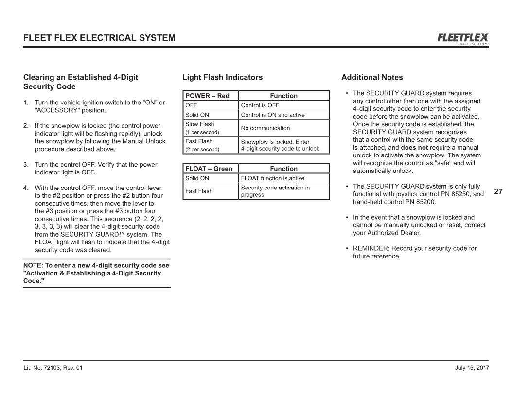
POWER – Red FunctionOFF Control is OFFSolid ON Control is ON and activeSlow Flash (1 per second)
No communication
Fast Flash(2 per second)
Snowplow is locked. Enter 4‑digit security code to unlock
FLOAT – Green FunctionSolid ON FLOAT function is active
Fast Flash Security code activation in progress
Additional Notes
• The SECURITY GUARD system requires any control other than one with the assigned 4‑digit security code to enter the security code before the snowplow can be activated. Once the security code is established, the SECURITY GUARD system recognizes that a control with the same security code is attached, and does not require a manual unlock to activate the snowplow. The system will recognize the control as "safe" and will automatically unlock.
• The SECURITY GUARD system is only fully functional with joystick control PN 85250, and hand‑held control PN 85200.
• In the event that a snowplow is locked and cannot be manually unlocked or reset, contact your Authorized Dealer.
• REMINDER: Record your security code for future reference.
FLEET FLEX ELECTRICAL SYSTEM

Lit. No. 72103, Rev. 01 July 15, 2017
28
Distributor Master Control
The Distributor Master Control (PN 78800) can clear an established code in a snowplow module without using the original control that was used to establish the code. This procedure should also be used to reset the module if the security code is unknown.
IMPORTANT: The following steps must be performed using the Distributor Master Control. Only the Distributor Master Control is programmed to clear an established security code when the original control used to establish the code is not available.
1. Turn the vehicle ignition to the "OFF" position.
2. With the control power OFF, using the tool that was included in the Distributor Master Control box, place the tool over the keypad, and push down on the plate.
NOTE: The only button that should be exposed is the LOWER button. All other buttons should be engaged and pressed down.
WARNINGTo prevent accidental movement of the blade, always turn the control OFF whenever the snowplow is not in use. The power indicator light will turn OFF.
AIS
LOWER
ON/OFFFLOAT
Position the Master Control Plate on the keypad so that only the LOWER button is exposed.
Master Control
Plate
LOWER Button
Keypad
3. Pushing the tool down will engage all functions except LOWER. While pushing down on the plate, turn the vehicle ignition ON.
4. When the ignition is turned to the "ON" position, the system will reset and the security code associated with the snowplow will be cleared.
FLEET FLEX ELECTRICAL SYSTEM
SECURITY GUARD™ Snowplow Anti-Theft System, continued

Lit. No. 72103, Rev. 01 July 15, 2017
29
ELECTRICAL & HYDRAULIC SCHEMATICS
The following section contains hydraulic and electrical schematics to help explain how the hydraulic unit performs the different functions. A schematic is an abstract drawing showing the purpose of each of the components in the system. Each component is represented by a symbol. The hydraulic and electrical legends describe each of the symbols used in the schematics for this guide.
The first two schematics show a general overview of the complete hydraulic and electrical systems. Other schematics highlight the flow of hydraulic fluid and electrical current for each function the hydraulic unit performs, as well as the flow of electrical current for snowplow and vehicle lights.
• Bold lines represent the circuit being activated.
• Shaded components are either activated or shifted from their normal position.
CHECK VALVE
ELECTRICAL LEGEND HYDRAULIC LEGEND
COMPONENT ENCLOSURE
FILTER, STRAINER,DIFFUSER
ELECTRIC MOTOR
RAM
HYDRAULIC PUMPFIXED DISPLACEMENT
LINE, TO RESERVOIRBELOW FLUID LEVEL
FLOW, DIRECTION OFHYDRAULIC FLUID
LINE, WORKING (MAIN)
LINES JOINING
LINES CROSSING
SOLENOID, SINGLE WINDING
VALVE, ADJUSTABLEPRESSURE RELIEF
VALVE, FLOW CONTROL,ADJUSTABLE NON-COMPENSATED
VALVE, 2 POSITION,2 CONNECTION (2-WAY)
VALVE, 2 POSITION,2 CONNECTION (2-WAY) WITH INTEGRALCHECK VALVE
SPRING
ORIFICE PLATE
PILOT-OPERATEDCHECK VALVE
VALVE, 2 POSITION,4 CONNECTION (4-WAY)
VALVE, 2 POSITION,3 CONNECTION (3-WAY)
CROSSING WIRE
WIRE SPLICE
IN-LINE CONNECTOR
FUSE
SOLENOID COIL
CIRCUIT GROUND
MOTOR RELAY
BATTERY
MOTOR
HEADLAMP
PARK/TURN LAMP
PRINTED CIRCUIT BOARD
COMPONENT ENCLOSURE

Lit. No. 72103, Rev. 01 July 15, 2017
30
ELECTRICAL & HYDRAULIC SCHEMATICS
S5
S4C2ORN
YEL
S3C2
RED
WHT
DKGRN
S3C1
S2
BRN
RED
S4C1
S5
12V
S4C2
S3C2
M/R (Motor)
12V
S3C1S2
RED
12V
DO/RIDO/RO
12V
COM
COM
MOTOR
PP SENSE
S4C1PUR
SP2
SP1
DKBLUS1
RED
RED
BLK
TANWHT
BLK
RED
EE
KJ
KJ
AA
EE
GH
FGH
F
CD
BCD
B
JJK K
GH
FGH
F
AA
CD
BCD
B
5A Fuses (2)
KJ
GH
F
DE
C
AB
A
B
C
S1
A B C D
5A Fuse
KJ
GH
F
DE
C
AB
NEG.
MOTORRELAY
POS.
X1
X2
PLOW MODULE
A B C D
PUMPMOTOR
Electrical Schematic – UTV V‑Plow

Lit. No. 72103, Rev. 01 July 15, 2017
31
ELECTRICAL & HYDRAULIC SCHEMATICS
PR
IMA
RY
MA
NIF
OLD
SECONDARY MANIFOLD
LIFT RAMROD END
M
BASE END
RV2
S1
S5
RV1TEST
AUX
QUILL
LEFT (DS) ANGLE RAMBASE END ROD END
RIGHT (PS) ANGLE RAMBASE END
RV3
RV5
CV4 CV1 PC1
RV4
RV6
PC2
CV2 CV3
S2
S4S4C2 S4C1
S3S3C1 S3C2
CV5
INTE
RFA
CE
PT
PUMP TANKINTERFACE
Hydraulic Schematic – UTV V‑Plow
Blade Movement
Solenoid
Motor M ON ON ON ON ON ON ON ON ONSV08‑2211 S1 ONSV10‑43 S2 ON ON
SV08‑47C S3C1 ON ON ONS3C2 ON
SV08‑47C S4C1 ON ON ONS4C2 ON ON ON
SVCV08‑20 S5 ON
VEE SCOOP EXTENDLEFTANGLE
LEFTANGLERIGHTRAISE LOWER
RIGHTRETRACT
RIGHTEXTEND
LEFTRETRACT
Relief Valve SettingsRV1 Pump 2000 ± 100 psi
RV2 Lift Ram Base End (Scrape Lock) 210 psi
RV3 DS Ram Rod End1150 ± 100 psi
RV4 PS Ram Rod EndRV5 DS Ram Base End
3000 ± 100 psiRV6 PS Ram Base End

Lit. No. 72103, Rev. 01 July 15, 2017
32
RAISE — ELECTRICAL
S5
S4C2ORN
YEL
S3C2
RED
WHT
DKGRN
S3C1
S2
BRN
RED
S4C1
S5
12V
S4C2
S3C2
M/R (Motor)
12V
S3C1S2
RED
12V
DO/RIDO/RO
12V
COM
COM
MOTOR
PP SENSE
S4C1PUR
SP2
SP1
DKBLUS1
RED
RED
BLK
TANWHT
BLK
RED
EE
KJ
KJ
AA
EE
GH
FGH
F
CD
BCD
B
JJK K
GH
FGH
F
AA
CD
BCD
B
KJ
GH
F
DE
C
AB
A
B
C
S1
A B C D
KJ
GH
F
DE
C
AB
NEG.
MOTORRELAY
POS.
X1
X2
PLOW MODULE
A B C D
PUMPMOTOR
5A Fuses (2)
5A Fuse
System Response
1. By activating the RAISE function on the cab control, the control sends a signal to the plow module to complete the ground path for the electrical circuit, activating the motor relay and solenoid cartridge valve S5.
2. Hydraulic fluid from the pump flows through the activated S5 and into the rod end of the lift ram, causing the ram to retract.
At the same time, fluid is forced out of the base of the ram, through the RV2 (scrape lock) relief valve, and returned to the reservoir.
NOTE: Battery voltage is supplied to the plow module, the motor relay, and the 7 solenoid coils when the snowplow is connected to the vehicle.

Lit. No. 72103, Rev. 01 July 15, 2017
33
PR
IMA
RY
MA
NIF
OLD
SECONDARY MANIFOLD
INTE
RFA
CE
PT
M
RV2
S1
S5
RV1TEST
AUX
QUILL
RV3
RV5
CV4 CV1 PC1
RV4
RV6
PC2
CV2 CV3
S2
S4S4C2 S4C1
S3S3C1 S3C2
CV5
PUMP TANK
ROD END BASE END
BASE END ROD END BASE ENDLIFT RAM
LEFT (DS) ANGLE RAM RIGHT (PS) ANGLE RAM
INTERFACE
RAISE — HYDRAULIC
Blade Movement
Solenoid
Motor M ON ON ON ON ON ON ON ON ONSV08‑2211 S1 ONSV10‑43 S2 ON ON
SV08‑47C S3C1 ON ON ONS3C2 ON
SV08‑47C S4C1 ON ON ONS4C2 ON ON ON
SVCV08‑20 S5 ON
VEE SCOOP EXTENDLEFTANGLE
LEFTANGLERIGHTRAISE LOWER
RIGHTRETRACT
RIGHTEXTEND
LEFTRETRACT
Lit. No. 72103, Rev. 01 July 15, 2017
34
LOWER/FLOAT — ELECTRICAL
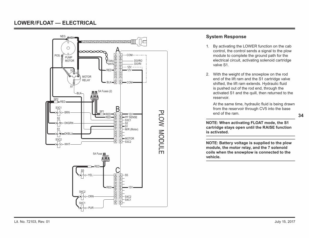
System Response
1. By activating the LOWER function on the cab control, the control sends a signal to the plow module to complete the ground path for the electrical circuit, activating solenoid cartridge valve S1.
2. With the weight of the snowplow on the rod end of the lift ram and the S1 cartridge valve shifted, the lift ram extends. Hydraulic fluid is pushed out of the rod end, through the activated S1 and the quill, then returned to the reservoir.
At the same time, hydraulic fluid is being drawn from the reservoir through CV5 into the base end of the ram.
NOTE: When activating FLOAT mode, the S1 cartridge stays open until the RAISE function is activated.
NOTE: Battery voltage is supplied to the plow module, the motor relay, and the 7 solenoid coils when the snowplow is connected to the vehicle.
S5
S4C2ORN
YEL
S3C2
RED
WHT
DKGRN
S3C1
S2
BRN
RED
S4C1
S5
12V
S4C2
S3C2
M/R (Motor)
12V
S3C1S2
RED
12V
DO/RIDO/RO
12V
COM
COM
MOTOR
PP SENSE
S4C1PUR
SP2
SP1
DKBLUS1
RED
RED
BLK
TANWHT
BLK
RED
EE
KJ
KJ
AA
EE
GH
FGH
F
CD
BCD
B
JJK K
GH
FGH
F
AA
CD
BCD
B
5A Fuses (2)
KJ
GH
F
DE
C
AB
A
B
C
S1
A B C D
5A Fuse
KJ
GH
F
DE
C
AB
NEG.
MOTORRELAY
POS.
X1
X2
PLOW MODULE
A B C D
PUMPMOTOR

Lit. No. 72103, Rev. 01 July 15, 2017
35
LOWER/FLOAT — HYDRAULIC
Blade Movement
Solenoid
Motor M ON ON ON ON ON ON ON ON ONSV08‑2211 S1 ONSV10‑43 S2 ON ON
SV08‑47C S3C1 ON ON ONS3C2 ON
SV08‑47C S4C1 ON ON ONS4C2 ON ON ON
SVCV08‑20 S5 ON
VEE SCOOP EXTENDLEFTANGLE
LEFTANGLERIGHTRAISE LOWER
RIGHTRETRACT
RIGHTEXTEND
LEFTRETRACT
PR
IMA
RY
MA
NIF
OLD
SECONDARY MANIFOLDM
RV2
S1
S5
RV1TEST
AUX
QUILL
RV3
RV5
CV4 CV1 PC1
RV4
RV6
PC2
CV2 CV3
S2
S4S4C2 S4C1
S3S3C1 S3C2
CV5
INTE
RFA
CE
PT
PUMP TANK
ROD END BASE END
BASE END ROD END BASE ENDLIFT RAM
LEFT (DS) ANGLE RAM RIGHT (PS) ANGLE RAM
INTERFACE

Lit. No. 72103, Rev. 01 July 15, 2017
36
ANGLE RIGHT — ELECTRICAL
System Response
1. By activating the angle right (R on the control face) function on the cab control, the control sends a signal to the plow module to complete the ground path for the electrical circuit, activating the motor relay and solenoid cartridge valves S4C2 and S2.
2. Hydraulic fluid from the pump flows through activated S4C2 and S2 cartridge valves and into the rod end of the right (PS) ram, causing the ram to retract.
3. The retracting right ram pushes hydraulic fluid out of the base end of the ram, through the activated PC2 pilot-activated check valve, back through the activated S2 and the PC1 valve. The fluid then enters the base end of the left (driver-side) ram, causing the ram to extend.
4. The extending left ram pushes hydraulic fluid out of the rod end of the ram and back through the activated S4C2 to the reservoir.
NOTE: Battery voltage is supplied to the plow module, the motor relay, and the 7 solenoid coils when the snowplow is connected to the vehicle.
S5
S4C2ORN
YEL
S3C2
RED
WHT
DKGRN
S3C1
S2
BRN
RED
S4C1
S5
12V
S4C2
S3C2
M/R (Motor)
12V
S3C1S2
RED
12V
DO/RIDO/RO
12V
COM
COM
MOTOR
PP SENSE
S4C1PUR
SP2
SP1
DKBLUS1
RED
RED
BLK
TANWHT
BLK
RED
EE
KJ
KJ
AA
EE
GH
FGH
F
CD
BCD
B
JJK K
GH
FGH
F
AA
CD
BCD
B
5A Fuses (2)
KJ
GH
F
DE
C
AB
A
B
C
S1
A B C D
5A Fuse
KJ
GH
F
DE
C
AB
NEG.
MOTORRELAY
POS.
X1
X2
PLOW MODULE
A B C D
PUMPMOTOR

Lit. No. 72103, Rev. 01 July 15, 2017
37
ANGLE RIGHT — HYDRAULIC
Blade Movement
Solenoid
Motor M ON ON ON ON ON ON ON ON ONSV08‑2211 S1 ONSV10‑43 S2 ON ON
SV08‑47C S3C1 ON ON ONS3C2 ON
SV08‑47C S4C1 ON ON ONS4C2 ON ON ON
SVCV08‑20 S5 ON
VEE SCOOP EXTENDLEFTANGLE
LEFTANGLERIGHTRAISE LOWER
RIGHTRETRACT
RIGHTEXTEND
LEFTRETRACT
PR
IMA
RY
MA
NIF
OLD
SECONDARY MANIFOLDM
RV2
S1
S5
RV1TEST
AUX
QUILL
RV3
RV5
CV4 CV1 PC1
RV4
RV6
PC2
CV2 CV3
S2
S4S4C2 S4C1
S3S3C1 S3C2
CV5
INTE
RFA
CE
PT
PUMP TANK
ROD END BASE END
BASE END ROD END BASE ENDLIFT RAM
LEFT (DS) ANGLE RAM RIGHT (PS) ANGLE RAM
INTERFACE
Lit. No. 72103, Rev. 01 July 15, 2017
38
ANGLE LEFT — ELECTRICAL
System Response
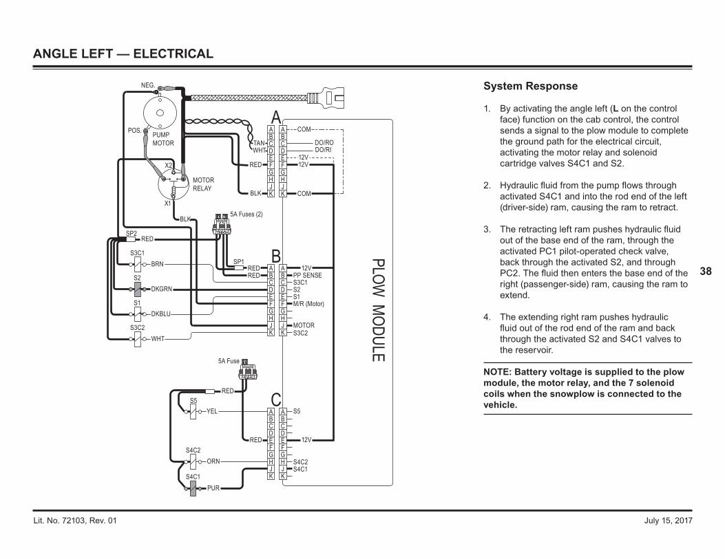
1. By activating the angle left (L on the control face) function on the cab control, the control sends a signal to the plow module to complete the ground path for the electrical circuit, activating the motor relay and solenoid cartridge valves S4C1 and S2.
2. Hydraulic fluid from the pump flows through activated S4C1 and into the rod end of the left (driver-side) ram, causing the ram to retract.
3. The retracting left ram pushes hydraulic fluid out of the base end of the ram, through the activated PC1 pilot-operated check valve, back through the activated S2, and through PC2. The fluid then enters the base end of the right (passenger-side) ram, causing the ram to extend.
4. The extending right ram pushes hydraulic fluid out of the rod end of the ram and back through the activated S2 and S4C1 valves to the reservoir.
NOTE: Battery voltage is supplied to the plow module, the motor relay, and the 7 solenoid coils when the snowplow is connected to the vehicle.S5
S4C2ORN
YEL
S3C2
RED
WHT
DKGRN
S3C1
S2
BRN
RED
S4C1
S5
12V
S4C2
S3C2
M/R (Motor)
12V
S3C1S2
RED
12V
DO/RIDO/RO
12V
COM
COM
MOTOR
PP SENSE
S4C1PUR
SP2
SP1
DKBLUS1
RED
RED
BLK
TANWHT
BLK
RED
EE
KJ
KJ
AA
EE
GH
FGH
F
CD
BCD
B
JJK K
GH
FGH
F
AA
CD
BCD
B
5A Fuses (2)
KJ
GH
F
DE
C
AB
A
B
C
S1
A B C D
5A Fuse
KJ
GH
F
DE
C
AB
NEG.
MOTORRELAY
POS.
X1
X2
PLOW MODULE
A B C D
PUMPMOTOR

Lit. No. 72103, Rev. 01 July 15, 2017
39
ANGLE LEFT — HYDRAULIC
Blade Movement
Solenoid
Motor M ON ON ON ON ON ON ON ON ONSV08‑2211 S1 ONSV10‑43 S2 ON ON
SV08‑47C S3C1 ON ON ONS3C2 ON
SV08‑47C S4C1 ON ON ONS4C2 ON ON ON
SVCV08‑20 S5 ON
VEE SCOOP EXTENDLEFTANGLE
LEFTANGLERIGHTRAISE LOWER
RIGHTRETRACT
RIGHTEXTEND
LEFTRETRACT
PR
IMA
RY
MA
NIF
OLD
SECONDARY MANIFOLDM
RV2
S1
S5
RV1TEST
AUX
QUILL
RV3
RV5
CV4 CV1 PC1
RV4
RV6
PC2
CV2 CV3
S2
S4S4C2
S4C1 S3S3C1 S3C2
CV5
INTE
RFA
CE
PT
PUMP TANK
ROD END BASE END
BASE END ROD END BASE ENDLIFT RAM
LEFT (DS) ANGLE RAM RIGHT (PS) ANGLE RAM
INTERFACE

Lit. No. 72103, Rev. 01 July 15, 2017
40
RETRACT (VEE) — ELECTRICAL
S5
S4C2ORN
YEL
S3C2
RED
WHT
DKGRN
S3C1
S2
BRN
RED
S4C1
S5
12V
S4C2
S3C2
M/R (Motor)
12V
S3C1S2
RED
12V
DO/RIDO/RO
12V
COM
COM
MOTOR
PP SENSE
S4C1PUR
SP2
SP1
DKBLUS1
RED
RED
BLK
TANWHT
BLK
RED
EE
KJ
KJ
AA
EE
GH
FGH
F
CD
BCD
B
JJK K
GH
FGH
F
AA
CD
BCD
B
5A Fuses (2)
KJ
GH
F
DE
C
AB
A
B
C
S1
A B C D
5A Fuse
KJ
GH
F
DE
C
AB
NEG.
MOTORRELAY
POS.
X1
X2
PLOW MODULE
A B C D
PUMPMOTOR
System Response
1. By activating the Retract (vee) function on the cab control, the control sends a signal to the plow module to complete the ground path for the electrical circuit, activating the motor relay and solenoid cartridge valves S4C1 and S3C2, activating these valves.
2. Hydraulic fluid from the pump flows through the activated S4C1 and S3C2 cartridge valves then into the rod end of both the driver‑side (DS) and passenger‑side (PS) angle rams, causing the rams to retract.
3. Pressure within the hydraulic circuit causes the PC1 and PC2 pilot‑operated check valves to open.
4. The retracting DS ram pushes hydraulic fluid out of the ram base end, through the activated PC1, through the inactive S2, and back through the activated S4C1 to the reservoir.
5. The retracting PS ram pushes the hydraulic fluid out of the ram base end, through the activated PC2, and back through the activated S3C2 to the reservoir.
NOTE: Battery voltage is supplied to the plow module, the motor relay, and the 7 solenoid coils when the snowplow is connected to the vehicle.

Lit. No. 72103, Rev. 01 July 15, 2017
41
RETRACT (VEE) — HYDRAULIC
Blade Movement
Solenoid
Motor M ON ON ON ON ON ON ON ON ONSV08‑2211 S1 ONSV10‑43 S2 ON ON
SV08‑47C S3C1 ON ON ONS3C2 ON
SV08‑47C S4C1 ON ON ONS4C2 ON ON ON
SVCV08‑20 S5 ON
VEE SCOOP EXTENDLEFTANGLE
LEFTANGLERIGHTRAISE LOWER
RIGHTRETRACT
RIGHTEXTEND
LEFTRETRACT
PR
IMA
RY
MA
NIF
OLD
SECONDARY MANIFOLDM
RV2
S1
S5
RV1TEST
AUX
QUILL
RV3
RV5
CV4 CV1 PC1
RV4
RV6
PC2
CV2 CV3
S2
S4S4C2 S4C1
S3S3C1 S3C2
CV5
INTE
RFA
CE
PT
PUMP TANK
ROD END BASE END
BASE END ROD END BASE ENDLIFT RAM
LEFT (DS) ANGLE RAM RIGHT (PS) ANGLE RAM
INTERFACE

Lit. No. 72103, Rev. 01 July 15, 2017
42
SCOOP — ELECTRICAL
System Response
1. By activating the SCOOP function on the cab control, the control sends a signal to the Plow Module to complete the ground path for the electrical circuit, activating the motor relay and solenoid cartridge valves S4C2 and S3C1.
2. Hydraulic fluid from the pump flows through activated S4C2 and S3C1 cartridge valves, through the PC1 and PC2 pilot‑operated check valves, then into the base end of both angle rams, causing the rams to extend.
3. The extending driver‑side ram pushes hydraulic fluid out of the ram rod end and back through the activated S4C2 to the reservoir.
4. The extending passenger‑side ram pushes hydraulic fluid out of the ram rod end and back through the activated S3C1 to the reservoir.
NOTE: Battery voltage is supplied to the plow module, the motor relay, and the 7 solenoid coils when the snowplow is connected to the vehicle.
S5
S4C2ORN
YEL
S3C2
RED
WHT
DKGRN
S3C1
S2
BRN
RED
S4C1
S5
12V
S4C2
S3C2
M/R (Motor)
12V
S3C1S2
RED
12V
DO/RIDO/RO
12V
COM
COM
MOTOR
PP SENSE
S4C1PUR
SP2
SP1
DKBLUS1
RED
RED
BLK
TANWHT
BLK
RED
EE
KJ
KJ
AA
EE
GH
FGH
F
CD
BCD
B
JJK K
GH
FGH
F
AA
CD
BCD
B
5A Fuses (2)
KJ
GH
F
DE
C
AB
A
B
C
S1
A B C D
5A Fuse
KJ
GH
F
DE
C
AB
NEG.
MOTORRELAY
POS.
X1
X2
PLOW MODULE
A B C D
PUMPMOTOR

Lit. No. 72103, Rev. 01 July 15, 2017
43
SCOOP — HYDRAULIC
Blade Movement
Solenoid
Motor M ON ON ON ON ON ON ON ON ONSV08‑2211 S1 ONSV10‑43 S2 ON ON
SV08‑47C S3C1 ON ON ONS3C2 ON
SV08‑47C S4C1 ON ON ONS4C2 ON ON ON
SVCV08‑20 S5 ON
VEE SCOOP EXTENDLEFTANGLE
LEFTANGLERIGHTRAISE LOWER
RIGHTRETRACT
RIGHTEXTEND
LEFTRETRACT
PR
IMA
RY
MA
NIF
OLD
SECONDARY MANIFOLDM
RV2
S1
S5
RV1TEST
AUX
QUILL
RV3
RV5
CV4 CV1 PC1
RV4
RV6
PC2
CV2 CV3
S2
S4S4C2 S4C1
S3S3C1 S3C2
CV5
INTE
RFA
CE
PT
PUMP TANK
ROD END BASE END
BASE END ROD END BASE ENDLIFT RAM
LEFT (DS) ANGLE RAM RIGHT (PS) ANGLE RAM
INTERFACE

Lit. No. 72103, Rev. 01 July 15, 2017
44
RIGHT (PS) WING EXTEND — ELECTRICAL
System Response
1. By activating the WING function (lower right corner on the control face) on the cab control, the control sends a signal to the plow module to complete the ground path for the electrical circuit, activating the motor relay and solenoid cartridge valve S3C1.
NOTE: The WING mode toggles back and forth between extend and retract functions.
2. Hydraulic fluid from the pump flows through the activated S3C1 and through the PC2 pilot‑operated check valve into the base end of the PS ram, causing it to extend.
3. The extending PS ram pushes hydraulic fluid out of the ram rod end and back through the activated S3C1 to the reservoir.
NOTE: Battery voltage is supplied to the plow module, the motor relay, and the 7 solenoid coils when the snowplow is connected to the vehicle.
S5
S4C2ORN
YEL
S3C2
RED
WHT
DKGRN
S3C1
S2
BRN
RED
S4C1
S5
12V
S4C2
S3C2
M/R (Motor)
12V
S3C1S2
RED
12V
DO/RIDO/RO
12V
COM
COM
MOTOR
PP SENSE
S4C1PUR
SP2
SP1
DKBLUS1
RED
RED
BLK
TANWHT
BLK
RED
EE
KJ
KJ
AA
EE
GH
FGH
F
CD
BCD
B
JJK K
GH
FGH
F
AA
CD
BCD
B
5A Fuses (2)
KJ
GH
F
DE
C
AB
A
B
C
S1
A B C D
5A Fuse
KJ
GH
F
DE
C
AB
NEG.
MOTORRELAY
POS.
X1
X2
PLOW MODULE
A B C D
PUMPMOTOR

Lit. No. 72103, Rev. 01 July 15, 2017
45
RIGHT (PS) WING EXTEND — HYDRAULIC
Blade Movement
Solenoid
Motor M ON ON ON ON ON ON ON ON ONSV08‑2211 S1 ONSV10‑43 S2 ON ON
SV08‑47C S3C1 ON ON ONS3C2 ON
SV08‑47C S4C1 ON ON ONS4C2 ON ON ON
SVCV08‑20 S5 ON
VEE SCOOP EXTENDLEFTANGLE
LEFTANGLERIGHTRAISE LOWER
RIGHTRETRACT
RIGHTEXTEND
LEFTRETRACT
PR
IMA
RY
MA
NIF
OLD
SECONDARY MANIFOLDM
RV2
S1
S5
RV1TEST
AUX
QUILL
RV3
RV5
CV4 CV1 PC1
RV4
RV6
PC2
CV2 CV3
S2
S4S4C2 S4C1
S3S3C1 S3C2
CV5
INTE
RFA
CE
PT
PUMP TANK
ROD END BASE END
BASE END ROD END BASE ENDLIFT RAM
LEFT (DS) ANGLE RAM RIGHT (PS) ANGLE RAM
INTERFACE

Lit. No. 72103, Rev. 01 July 15, 2017
46
RIGHT (PS) WING RETRACT — ELECTRICAL
System Response
1. By activating the WING function (lower right corner on the control face) on the cab control, the control sends a signal to the plow module to complete the ground path for the electrical circuit, activating the motor relay and solenoid cartridge valve S3C2.
NOTE: The WING mode toggles back and forth between retract and extend functions.
2. Hydraulic fluid from the pump flows through the activated S3C2 into the rod end of the PS ram, causing it to retract.
3. Pressure within this hydraulic circuit causes the PC2 pilot‑operated check valve to open.
4. The retracting PS ram pushes hydraulic fluid out of the ram base end, through the activated PC2, and back through the activated S3C2 to the reservoir.
NOTE: Battery voltage is supplied to the plow module, the motor relay, and the 7 solenoid coils when the snowplow is connected to the vehicle.
S5
S4C2ORN
YEL
S3C2
RED
WHT
DKGRN
S3C1
S2
BRN
RED
S4C1
S5
12V
S4C2
S3C2
M/R (Motor)
12V
S3C1S2
RED
12V
DO/RIDO/RO
12V
COM
COM
MOTOR
PP SENSE
S4C1PUR
SP2
SP1
DKBLUS1
RED
RED
BLK
TANWHT
BLK
RED
EE
KJ
KJ
AA
EE
GH
FGH
F
CD
BCD
B
JJK K
GH
FGH
F
AA
CD
BCD
B
5A Fuses (2)
KJ
GH
F
DE
C
AB
A
B
C
S1
A B C D
5A Fuse
KJ
GH
F
DE
C
AB
NEG.
MOTORRELAY
POS.
X1
X2
PLOW MODULE
A B C D
PUMPMOTOR

Lit. No. 72103, Rev. 01 July 15, 2017
47
RIGHT (PS) WING RETRACT — HYDRAULIC
Blade Movement
Solenoid
Motor M ON ON ON ON ON ON ON ON ONSV08‑2211 S1 ONSV10‑43 S2 ON ON
SV08‑47C S3C1 ON ON ONS3C2 ON
SV08‑47C S4C1 ON ON ONS4C2 ON ON ON
SVCV08‑20 S5 ON
VEE SCOOP EXTENDLEFTANGLE
LEFTANGLERIGHTRAISE LOWER
RIGHTRETRACT
RIGHTEXTEND
LEFTRETRACT
PR
IMA
RY
MA
NIF
OLD
SECONDARY MANIFOLDM
RV2
S1
S5
RV1TEST
AUX
QUILL
RV3
RV5
CV4 CV1 PC1
RV4
RV6
PC2
CV2 CV3
S2
S4S4C2 S4C1
S3S3C1 S3C2
CV5
INTE
RFA
CE
PT
PUMP TANK
ROD END BASE END
BASE END ROD END BASE ENDLIFT RAM
LEFT (DS) ANGLE RAM RIGHT (PS) ANGLE RAM
INTERFACE

Lit. No. 72103, Rev. 01 July 15, 2017
48
LEFT (DS) WING EXTEND — ELECTRICAL
System Response
1. By activating the WING function (lower left corner on the control face) on the cab control, the control sends a signal to the plow module to complete the ground path for the electrical circuit, activating the motor relay and solenoid cartridge valve S4C2.
NOTE: The WING mode toggles back and forth between extend and retract functions.
2. Hydraulic fluid from the pump flows through the activated S4C2 and inactive S2, through the PC1 pilot‑operated check valve into the base end of the DS ram, causing it to extend.
3. The extending DS ram pushes hydraulic fluid out of the ram rod end and back through the activated S4C2 to the reservoir.
NOTE: Battery voltage is supplied to the plow module, the motor relay, and the 7 solenoid coils when the snowplow is connected to the vehicle.
S5
S4C2ORN
YEL
S3C2
RED
WHT
DKGRN
S3C1
S2
BRN
RED
S4C1
S5
12V
S4C2
S3C2
M/R (Motor)
12V
S3C1S2
RED
12V
DO/RIDO/RO
12V
COM
COM
MOTOR
PP SENSE
S4C1PUR
SP2
SP1
DKBLUS1
RED
RED
BLK
TANWHT
BLK
RED
EE
KJ
KJ
AA
EE
GH
FGH
F
CD
BCD
B
JJK K
GH
FGH
F
AA
CD
BCD
B
5A Fuses (2)
KJ
GH
F
DE
C
AB
A
B
C
S1
A B C D
5A Fuse
KJ
GH
F
DE
C
AB
NEG.
MOTORRELAY
POS.
X1
X2
PLOW MODULE
A B C D
PUMPMOTOR

Lit. No. 72103, Rev. 01 July 15, 2017
49
LEFT (DS) WING EXTEND — HYDRAULIC
Blade Movement
Solenoid
Motor M ON ON ON ON ON ON ON ON ONSV08‑2211 S1 ONSV10‑43 S2 ON ON
SV08‑47C S3C1 ON ON ONS3C2 ON
SV08‑47C S4C1 ON ON ONS4C2 ON ON ON
SVCV08‑20 S5 ON
VEE SCOOP EXTENDLEFTANGLE
LEFTANGLERIGHTRAISE LOWER
RIGHTRETRACT
RIGHTEXTEND
LEFTRETRACT
PR
IMA
RY
MA
NIF
OLD
SECONDARY MANIFOLDM
RV2
S1
S5
RV1TEST
AUX
QUILL
RV3
RV5
CV4 CV1 PC1
RV4
RV6
PC2
CV2 CV3
S2
S4S4C2 S4C1
S3S3C1 S3C2
CV5
INTE
RFA
CE
PT
PUMP TANK
ROD END BASE END
BASE END ROD END BASE ENDLIFT RAM
LEFT (DS) ANGLE RAM RIGHT (PS) ANGLE RAM
INTERFACE

Lit. No. 72103, Rev. 01 July 15, 2017
50
LEFT (DS) WING RETRACT — ELECTRICAL
System Response
1. By activating the WING function (lower left corner on the control face) on the cab control, the control sends a signal to the plow module to complete the ground path for the electrical circuit, activating the motor relay and solenoid cartridge valve S4C1.
NOTE: The WING mode toggles back and forth between retract and extend functions.
2. Hydraulic fluid from the pump flows through the activated S4C1 cartridge valve and into the rod end of the DS ram, causing it to retract.
3. Pressure within this hydraulic circuit causes the PC1 pilot‑operated check valve to open.
4. The retracting DS ram pushes hydraulic fluid out of the ram base end, through the activated PC1 and the inactive S2, then back through the activated S4C1 to the reservoir.
NOTE: Battery voltage is supplied to the plow module, the motor relay, and the 7 solenoid coils when the snowplow is connected to the vehicle.
S5
S4C2ORN
YEL
S3C2
RED
WHT
DKGRN
S3C1
S2
BRN
RED
S4C1
S5
12V
S4C2
S3C2
M/R (Motor)
12V
S3C1S2
RED
12V
DO/RIDO/RO
12V
COM
COM
MOTOR
PP SENSE
S4C1PUR
SP2
SP1
DKBLUS1
RED
RED
BLK
TANWHT
BLK
RED
EE
KJ
KJ
AA
EE
GH
FGH
F
CD
BCD
B
JJK K
GH
FGH
F
AA
CD
BCD
B
5A Fuses (2)
KJ
GH
F
DE
C
AB
A
B
C
S1
A B C D
5A Fuse
KJ
GH
F
DE
C
AB
NEG.
MOTORRELAY
POS.
X1
X2
PLOW MODULE
A B C D
PUMPMOTOR

Lit. No. 72103, Rev. 01 July 15, 2017
51
LEFT (DS) WING RETRACT — HYDRAULIC
Blade Movement
Solenoid
Motor M ON ON ON ON ON ON ON ON ONSV08‑2211 S1 ONSV10‑43 S2 ON ON
SV08‑47C S3C1 ON ON ONS3C2 ON
SV08‑47C S4C1 ON ON ONS4C2 ON ON ON
SVCV08‑20 S5 ON
VEE SCOOP EXTENDLEFTANGLE
LEFTANGLERIGHTRAISE LOWER
RIGHTRETRACT
RIGHTEXTEND
LEFTRETRACT
PR
IMA
RY
MA
NIF
OLD
SECONDARY MANIFOLDM
RV2
S1
S5
RV1TEST
AUX
QUILL
RV3
RV5
CV4 CV1 PC1
RV4
RV6
PC2
CV2 CV3
S2
S4S4C2 S4C1
S3S3C1 S3C2
CV5
INTE
RFA
CE
PT
PUMP TANK
ROD END BASE END
BASE END ROD END BASE ENDLIFT RAM
LEFT (DS) ANGLE RAM RIGHT (PS) ANGLE RAM
INTERFACE

Lit. No. 72103, Rev. 01 July 15, 2017
52
HOLD IN RAISE POSITION
System Response
Hydraulic fluid is trapped in the rod end of the lift ram by the internal check valves located in solenoid cartridge valves S5 and S1.
PR
IMA
RY
MA
NIF
OLD
ROD END
M
BASE END
RV2
S1
S5
RV1TEST
AUX
QUILL
CV5IN
TER
FAC
EP
T
LIFT RAM
SECONDARY MANIFOLD
BASE END ROD END BASE END
RV3
RV5
CV4 CV1 PC1
RV4
RV6
PC2
CV2 CV3
S2
S4S4C2 S4C1
S3S3C1 S3C2
PUMP TANK
LEFT (DS) ANGLE RAM RIGHT (PS) ANGLE RAM
INTERFACE

Lit. No. 72103, Rev. 01 July 15, 2017
53
STRIKING AN OBJECT WHILE PLOWING FORWARD — HYDRAULIC
System Response
1. Hydraulic fluid is trapped in the base end of the driver‑side ram by the CV4 check valve RV5 relief valve and PC1 pilot‑operated check valve.
2. Hydraulic fluid is trapped in the base end of the passenger‑side ram by the CV3 check valve, RV6 relief valve, and PC2 pilot-operated check valve.
PR
IMA
RY
MA
NIF
OLD
SECONDARY MANIFOLD
ROD END
M
BASE END
RV2
S1
S5
RV1TEST
AUX
QUILL
BASE END ROD END BASE END
RV3
RV5
CV4 CV1 PC1
RV4
RV6
PC2
CV2 CV3
S2
S4S4C2 S4C1
S3S3C1 S3C2
CV5
INTE
RFA
CE
PT
PUMP TANK
LIFT RAM
LEFT (DS) ANGLE RAM RIGHT (PS) ANGLE RAM
INTERFACE
3. When the snowplow contacts an object while plowing, the force of the impact increases hydraulic pressure in the base end of the ram. When the pressure exceeds 3000 psi, the ram's base end relief valve opens (RV5 on DS, RV6 on PS), allowing fluid to flow back to the reservoir.
4. Due to the small volume on the rod side of the piston, fluid is not replaced. This causes a slight temporary vacuum in that circuit

Lit. No. 72103, Rev. 01 July 15, 2017
54
STRIKING AN OBJECT WHILE BACK DRAGGING — HYDRAULIC
System Response
1. Hydraulic fluid is trapped in the rod end of the driver‑side ram by the inactivated S4 solenoid cartridge valve and the RV3 rod end relief valve.
2. Hydraulic fluid is trapped in the rod end of the passenger‑side ram by the inactivated S3 solenoid cartridge valve and RV4 rod end relief valve.
3. When the snowplow contacts an object while back dragging, force of the impact increases hydraulic pressure in the rod end of the ram. When the pressure exceeds 1150 psi, the ram's rod end relief valve opens (RV3 on DS, RV4 on PS), allowing fluid to flow into the ram's base end.
4. Because of differential volume on either side of the ram's piston, fluid is drawn from the reservoir through CV4 (on DS) or CV3 (on PS) to the base end of the ram.
PR
IMA
RY
MA
NIF
OLD
SECONDARY MANIFOLD
ROD END
M
BASE END
RV2
S1
S5
RV1TEST
AUX
QUILL
BASE END ROD END BASE END
RV3
RV5
CV4 CV1 PC1
RV4
RV6
PC2
CV2 CV3
S2
S4S4C2 S4C1
S3S3C1 S3C2
CV5
INTE
RFA
CE
PT
PUMP TANK
LIFT RAM
LEFT (DS) ANGLE RAM RIGHT (PS) ANGLE RAM
INTERFACE

Lit. No. 72103, Rev. 01 July 15, 2017
55
Troubleshooting Guide

Lit. No. 72103, Rev. 01 July 15, 2017
56
TROUBLESHOOTING GUIDE
ELECTRICAL TESTING
A simple 12‑volt (12 V) test light with a ground lead can be used for circuit testing in most cases. The exception is the paired multiplex wiring, which carries a low‑level signal from the control to the plow module. In this case, an ohmmeter may be used to check continuity.
When directed to check for 12 V, ground the test lamp lead and probe the terminal.
When asked to check for ground, attach the test lamp lead to +12 V and probe the terminal.
NOTE: 12 V is a nominal value. If using a voltmeter, actual voltage will vary with the vehicle and presence of loads in tested circuits. Continuity alone does not guarantee a good circuit. Poor connectors or damaged wires may have continuity but be unable to carry sufficient current.
CAUTIONDo not probe wires. Doing so will damage the wire insulation, causing the wire to fail prematurely.
HOW TO USE THE TROUBLESHOOTING GUIDE
All malfunctions of the IMPACT™ UTV V-plow can be categorized as structural, electrical, or hydraulic. Structural issues are generally related to the blade, T-frame, lift frame, and mount components, and are usually identified by visual inspection. Electrical and hydraulic issues, however, can be more difficult to trace.
Because of the relative complexity of the hydraulic system, some conditions must be met in order to develop valid tests. If the listed conditions are not met, the procedure can result in inaccurate results and wasted time.
Go to the "Before You Begin" instructions on the next page and satisfy the listed conditions before starting any testing. In many cases, satisfying the listed conditions alone solves the problem.
Follow along sequentially through the tables and tests, referring to the relevant sections of this manual as needed.
FUSE REPLACEMENT
The vehicle control harness contains one 2 A blade‑style mini fuse and the hydraulic unit contains three 5 A blade‑style mini fuses. (See schematics on pages 19 and 30).
The control fuse is "hot" when the vehicle ignition switch is ON.
If a problem should occur and fuse replacement is necessary, the replacement fuse must be of the same type and amperage rating as the original. Installing a fuse with a higher rating can damage the system and could start a fire.

Lit. No. 72103, Rev. 01 July 15, 2017
57
g. The hydraulic reservoir is filled to the proper level with recommended fluid when the blade is sitting on the ground in the retracted (vee) position, with the vehicle setting level. Fluid level should be 1-1/2" to 2" below the top of the fill hole.
h. There are no fluid leaks from hoses, fittings, rams, or the hydraulic unit.
i. All hoses are routed correctly.
TROUBLESHOOTING GUIDE
BEFORE YOU BEGIN
Before proceeding, or carrying out any tests, you must verify the following conditions:
1. Verify that the customer has accurately and completely described the problem. Observe all snowplow functions.
2. Check the obvious, to confirm that:
a. The snowplow is attached to the vehicle and all harnesses are connected.
b. The ignition is turned ON, or engine is running if operating the control from within the cab.
c. The control is connected in the cab and turned ON. The control power LED is in a steady state and is not flashing.
d. The fuses are good.
e. The vehicle battery and charging system are in good condition, and battery connections are clean and tight.
f. Harness connector pins and terminals are free of corrosion, ensuring good connections, and coated with dielectric grease.
CAUTIONFill the reservoir to the fill level only. Do not overfill. Overfilling could damage the unit.
CAUTIONDo not mix different types of hydraulic fluid. Some fluids are not compatible and may cause performance problems and product damage.
j. Coil wire connections are secure and correct.
k. Correct cartridges are installed in the proper locations.
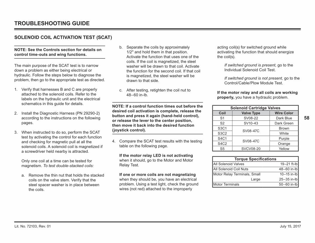
Lit. No. 72103, Rev. 01 July 15, 2017
58
TROUBLESHOOTING GUIDE
NOTE: See the Controls section for details on control time‑outs and wing functions.
The main purpose of the SCAT test is to narrow down a problem as either being electrical or hydraulic. Follow the steps below to diagnose the problem, then go to the appropriate test as directed.
1. Verify that harnesses B and C are properly attached to the solenoid coils. Refer to the labels on the hydraulic unit and the electrical schematics in this guide for details.
2. Install the Diagnostic Harness (PN 29290‑2) according to the instructions on the following pages.
3. When instructed to do so, perform the SCAT test by activating the control for each function and checking for magnetic pull at all the solenoid coils. A solenoid coil is magnetized if a screwdriver held nearby is attracted. Only one coil at a time can be tested for magnetism. To test double-stacked coils:
a. Remove the thin nut that holds the stacked coils on the valve stem. Verify that the steel spacer washer is in place between the coils.
SOLENOID COIL ACTIVATION TEST (SCAT)
b. Separate the coils by approximately 1/2" and hold them in that position. Activate the function that uses one of the coils. If the coil is magnetized, the steel washer will be drawn to that coil. Activate the function for the second coil. If that coil is magnetized, the steel washer will be drawn to that side.
c. After testing, retighten the coil nut to 48–60 in‑lb.
NOTE: If a control function times out before the desired coil activation is complete, release the button and press it again (hand‑held control), or release the lever to the center position, then move it back into the desired function (joystick control).
4. Compare the SCAT test results with the testing table on the following page.
If the motor relay LED is not activating when it should, go to the Motor and Motor Relay Test.
If one or more coils are not magnetizing when they should be, you have an electrical problem. Using a test light, check the ground wires (not red) attached to the improperly
acting coil(s) for switched ground while activating the function that should energize the coil(s).
If switched ground is present, go to the Individual Solenoid Coil Test.
If switched ground is not present, go to the Control/Cable/Plow Module Test.
If the motor relay and all coils are working properly, you have a hydraulic problem.
Solenoid Cartridge ValvesCoil Valve Type Wire ColorS1 SV08‑22 Dark BlueS2 SV10‑43 Dark Green
S3C1SV08‑47C
BrownS3C2 WhiteS4C1
SV08‑47CPurple
S4C2 OrangeS5 SVCV08‑20 Yellow
Torque SpecificationsAll Solenoid Valves 19–21 ft‑lbAll Solenoid Coil Nuts 48–60 in‑lbMotor Relay Terminals, Small 10–15 in‑lb
Large 25–35 in‑lbMotor Terminals 50–60 in‑lb
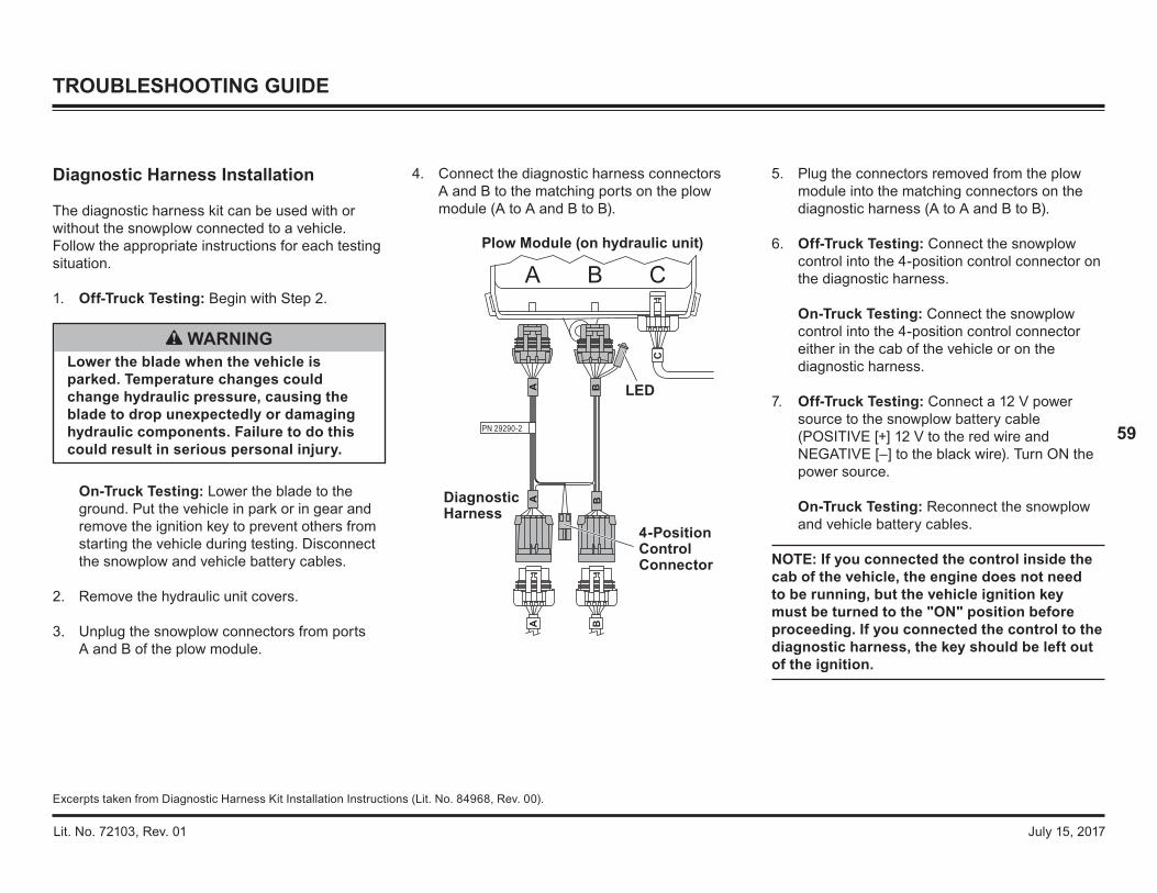
Lit. No. 72103, Rev. 01 July 15, 2017
59
TROUBLESHOOTING GUIDE
Excerpts taken from Diagnostic Harness Kit Installation Instructions (Lit. No. 84968, Rev. 00).
4. Connect the diagnostic harness connectors A and B to the matching ports on the plow module (A to A and B to B).
Diagnostic Harness Installation
The diagnostic harness kit can be used with or without the snowplow connected to a vehicle. Follow the appropriate instructions for each testing situation.
1. Off‑Truck Testing: Begin with Step 2.
On‑Truck Testing: Lower the blade to the ground. Put the vehicle in park or in gear and remove the ignition key to prevent others from starting the vehicle during testing. Disconnect the snowplow and vehicle battery cables.
2. Remove the hydraulic unit covers.
3. Unplug the snowplow connectors from ports A and B of the plow module.
WARNINGLower the blade when the vehicle is parked. Temperature changes could change hydraulic pressure, causing the blade to drop unexpectedly or damaging hydraulic components. Failure to do this could result in serious personal injury.
DiagnosticHarness
4-PositionControlConnector
LED
Plow Module (on hydraulic unit)
PN 29290-2
5. Plug the connectors removed from the plow module into the matching connectors on the diagnostic harness (A to A and B to B).
6. Off‑Truck Testing: Connect the snowplow control into the 4‑position control connector on the diagnostic harness. On‑Truck Testing: Connect the snowplow control into the 4‑position control connector either in the cab of the vehicle or on the diagnostic harness.
7. Off‑Truck Testing: Connect a 12 V power source to the snowplow battery cable (POSITIVE [+] 12 V to the red wire and NEGATIVE [–] to the black wire). Turn ON the power source. On‑Truck Testing: Reconnect the snowplow and vehicle battery cables.
NOTE: If you connected the control inside the cab of the vehicle, the engine does not need to be running, but the vehicle ignition key must be turned to the "ON" position before proceeding. If you connected the control to the diagnostic harness, the key should be left out of the ignition.

Lit. No. 72103, Rev. 01 July 15, 2017
60
TROUBLESHOOTING GUIDE
Solenoid Coil Activation Test (SCAT), continued
8. Turn the snowplow control ON and perform a Solenoid Coil Activation Test (SCAT) for each control function. Refer to the table for solenoid numbers and functions.
NOTE: The green LED on the diagnostic harness will illuminate when the motor relay function is activated. This light only tests the plow module's motor relay output.
NOTE: If a control function times out before the desired coil activation is complete, release the button and press it again (hand‑held control), or release the lever to the center position, then move it back into the desired function (joystick control).
S1
S4C2
S2
S4C1S3C2
S5
S3C1
Control Function Solenoid Coil(s) ActivatedRaise S5, motor relay
Lower/Float S1Angle Right S2, S4C2, motor relayAngle Left S2, S4C1, motor relay
R Wing Extend S3C1, motor relayR Wing Retract S3C2, motor relayL Wing Extend S4C2, motor relayL Wing Retract S4C1, motor relay
Scoop S3C1, S4C2, motor relayVee S3C2, S4C1, motor relay
9. After completing the SCAT test, turn the snowplow control OFF. Off‑Truck Testing: Disconnect the 12 V power source.
On‑Truck Testing: Turn the vehicle ignition OFF. Disconnect the snowplow and vehicle battery cables.
10. Perform any required repairs and retest as needed.
11. When testing is completed, disconnect the power source or the snowplow and vehicle battery cables as described in Step 9 before unplugging the diagnostic harness. Plug the snowplow connectors back into ports A and B of the plow module.
12. Replace the hydraulic unit covers. After On‑Truck Testing: Reconnect the snowplow and vehicle battery cables.

Lit. No. 72103, Rev. 01 July 15, 2017
61
TROUBLESHOOTING GUIDE
INDIVIDUAL SOLENOID COIL TEST
1. Remove both wires from coil terminals.
2. Attach an ohmmeter across the coil terminals.
3. A reading that is not approximately 7 ohms indicates coil is damaged and must be replaced.
4. Attach an ohmmeter to one coil terminal and to the steel washer at the end of the coil.
5. A reading that is not "open" indicates that the coil has internal shorts and needs to be replaced.
6. If both readings are approximately 7 ohms across terminals and "open" between terminal and washer, then the coil is good.
NOTE: A good coil will draw approximately 1.5 A.
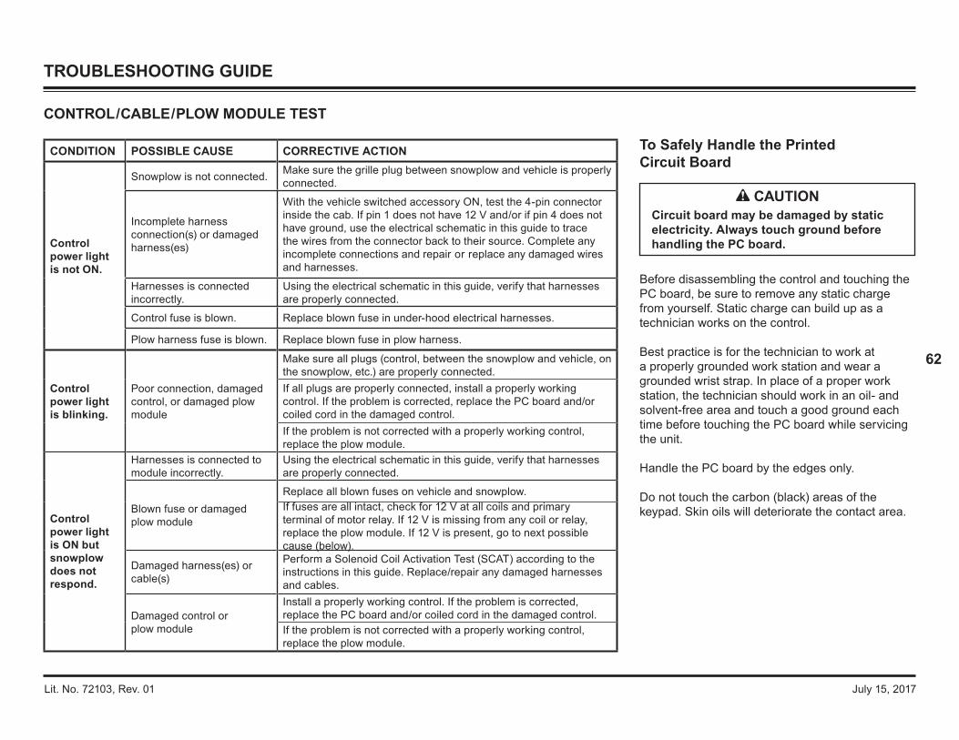
Lit. No. 72103, Rev. 01 July 15, 2017
62
To Safely Handle the Printed Circuit Board
Before disassembling the control and touching the PC board, be sure to remove any static charge from yourself. Static charge can build up as a technician works on the control.
Best practice is for the technician to work at a properly grounded work station and wear a grounded wrist strap. In place of a proper work station, the technician should work in an oil- and solvent‑free area and touch a good ground each time before touching the PC board while servicing the unit.
Handle the PC board by the edges only.
Do not touch the carbon (black) areas of the keypad. Skin oils will deteriorate the contact area.
TROUBLESHOOTING GUIDE
CAUTIONCircuit board may be damaged by static electricity. Always touch ground before handling the PC board.
CONTROL/CABLE/PLOW MODULE TEST
CONDITION POSSIBLE CAUSE CORRECTIVE ACTION
Control power light is not ON.
Snowplow is not connected. Make sure the grille plug between snowplow and vehicle is properly connected.
Incomplete harness connection(s) or damaged harness(es)
With the vehicle switched accessory ON, test the 4-pin connector inside the cab. If pin 1 does not have 12 V and/or if pin 4 does not have ground, use the electrical schematic in this guide to trace the wires from the connector back to their source. Complete any incomplete connections and repair or replace any damaged wires and harnesses.
Harnesses is connected incorrectly.
Using the electrical schematic in this guide, verify that harnesses are properly connected.
Control fuse is blown. Replace blown fuse in under‑hood electrical harnesses.
Plow harness fuse is blown. Replace blown fuse in plow harness.
Control power light is blinking.
Poor connection, damaged control, or damaged plow module
Make sure all plugs (control, between the snowplow and vehicle, on the snowplow, etc.) are properly connected.If all plugs are properly connected, install a properly working control. If the problem is corrected, replace the PC board and/or coiled cord in the damaged control.If the problem is not corrected with a properly working control, replace the plow module.
Control power light is ON but snowplow does not respond.
Harnesses is connected to module incorrectly.
Using the electrical schematic in this guide, verify that harnesses are properly connected.
Blown fuse or damaged plow module
Replace all blown fuses on vehicle and snowplow.If fuses are all intact, check for 12 V at all coils and primary terminal of motor relay. If 12 V is missing from any coil or relay, replace the plow module. If 12 V is present, go to next possible cause (below).
Damaged harness(es) or cable(s)
Perform a Solenoid Coil Activation Test (SCAT) according to the instructions in this guide. Replace/repair any damaged harnesses and cables.
Damaged control or plow module
Install a properly working control. If the problem is corrected, replace the PC board and/or coiled cord in the damaged control.If the problem is not corrected with a properly working control, replace the plow module.
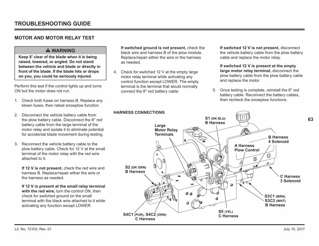
Lit. No. 72103, Rev. 01 July 15, 2017
63
TROUBLESHOOTING GUIDE
WARNINGKeep 8' clear of the blade when it is being raised, lowered, or angled. Do not stand between the vehicle and blade or directly in front of the blade. If the blade hits or drops on you, you could be seriously injured.
Perform this test if the control lights up and turns ON but the motor does not run.
1. Check both fuses on harness B. Replace any blown fuses, then retest snowplow function.
2. Disconnect the vehicle battery cable from the plow battery cable. Disconnect the 8" red battery cable from the large terminal of the motor relay and isolate it to eliminate potential for accidental blade movement during testing.
3. Reconnect the vehicle battery cable to the plow battery cable. Check for 12 V at the small terminal of the motor relay with the red wire attached to it.
If 12 V is not present, check the red wire and harness B. Replace/repair either the wire or the harness as needed.
If 12 V is present at the small relay terminal with the red wire, turn the control ON, then check for switched ground on the small terminal with the black wire attached to it while activating any function except LOWER.
If switched ground is not present, check the black wire and harness B of the plow module. Replace/repair either the wire or the harness as needed.
4. Check for switched 12 V at the empty large motor relay terminal while activating any control function except LOWER. The empty terminal is the terminal that would normally connect the 8" red battery cable.
MOTOR AND MOTOR RELAY TEST
If switched 12 V is not present, disconnect the vehicle battery cable from the plow battery cable and replace the motor relay.
If switched 12 V is present at the empty large motor relay terminal, disconnect the plow battery cable from the plow battery cable and replace the motor.
5. Once testing is complete, reinstall the 8" red battery cable. Reconnect the battery cables, then recheck the snowplow functions.
A HarnessPlow Control
S4C1 (PUR), S4C2 (ORN) C Harness
S3C1 (BRN),S3C2 (WHT)B Harness
S2 (DK GRN) B Harness
S5 (YEL) C Harness
S1 (DK BLU) B Harness
B Harness4 Solenoid
C Harness3 Solenoid
Large Motor Relay Terminals
HARNESS CONNECTIONS

Lit. No. 72103, Rev. 01 July 15, 2017
64
TROUBLESHOOTING GUIDE
PUMP PRESSURE TEST
NOTE: Reservoir will contain residual pressure. Slowly remove, then reinstall, the breather to release pressure before proceeding.
1. Lower the blade to the ground. Verify proper fluid level before running the test.
2. Attach a 3000 psi hydraulic pressure gauge to the pressure test port in the location shown.
3. Activate the right RETRACT function until the wing is fully retracted.
NOTE: The control will time out after 3 seconds. Repeat the command if the blade is not yet fully retracted.
4. Repeat the right RETRACT function and read the pressure shown on the gauge.
5. Refer to the table to determine the necessary corrective action. Do not adjust the pressure setting more than 1/4 turn at a time. Do not adjust the relief valve while the motor is running.
CONDITION POSSIBLE CAUSE CORRECTIVE ACTION
Pump pressure is below 2000 ± 100 psi.
Pump Relief Valve
The pump relief valve may be out of adjustment. Turn the relief valve clockwise 1/4 turn and retest the pressure. Repeat until correct pressure (2000 ± 100 psi) is obtained.If correct pressure is not obtained after readjustment, remove and inspect the relief valve and its components. Check the O-ring, stem, and ball for wear or damage. Reseat the ball or replace the relief valve as needed. Reinstall/replace and readjust the valve, then retest pump pressure.
O‑Ring (between pump and valve block)
Remove the pump and inspect the O‑ring between the pump and the valve block for wear or damage. Reinstall/replace the O-ring and pump, then retest pump pressure.
PumpRemove the pump and inspect it for wear or broken gears. Replace the pump if needed, adjust the pump relief valve, then retest pressure.
Motor draws more than 190 A at pump relief.
Motor Replace the motor.
NOTE: See the following page for Relief Valve Inspection and Adjustment instructions.
Test Port
PressureGauge
FemaleConnector
Hose
90° Elbow
Short Connector
WARNINGThe tester shall keep bystanders 8' clear of the blade during these tests. Do not stand between the vehicle and the blade or within 8 feet of a moving blade. A moving or falling blade could cause personal injury.

Lit. No. 72103, Rev. 01 July 15, 2017
65
Relief valve RV2 and components are not interchangeable with the other relief valves.
NOTE: The spring for relief valve RV2 is different from the other springs and should not be interchanged. The RV2 spring is made of a lighter wire and is gold in color.
Inspection
1. Remove the valve stem, ball, spacer, and spring.
2. Look for broken or damaged parts, contamination, or missing or damaged O-rings.
3. If all the parts are in good condition, place the ball on a hardwood block, hold the stem seat on the ball, and lightly strike the top of the stem with a hammer. This will seat the ball and valve stem.
4. Apply a light coat of anti‑seize or grease to the stem threads. Lubricate the O‑rings with hydraulic fluid. Reassemble the components into the valve block.
Adjustment
1. Screw the valve stem inward until the spring is fully compressed.
2. Back out the valve stem by turning it counterclockwise (CCW) the number of turns indicated in the table.
CAUTIONBe careful to strike the valve stem squarely. You can bend the stem if you do not strike it squarely.
CAUTIONNever operate the unit while adjusting the relief valve. Doing so will damage the relief valve O‑rings.
TROUBLESHOOTING GUIDE
RELIEF VALVE INSPECTION AND ADJUSTMENT
Relief Valve Approx. Pressure # of Turns CCW from Fully Seated
RV1 Pump 2000 ± 100 psi 2
RV2 Lift Ram Base End (Scrape Lock) 210 psi 1‑3/4
RV3 DS Ram Rod End1150 ± 100 psi 2‑5/8
RV4 PS Ram Rod EndRV5 DS Ram Base End
3000 ± 100 psi 1‑3/8RV6 PS Ram Base End
Primary Manifold
Secondary Manifold
RV1
RV2
RV3
Pressure Test Port
RV4RV5
RV6
Spring
Spacer
Valve Stemw/O-Rings
Ball

Lit. No. 72103, Rev. 01 July 15, 2017
66
6. Retighten the breather/fill plug.
7. Reconnect the snowplow battery cable to the vehicle battery cable. Turn the vehicle ignition and snowplow control ON.
8. Raise the blade high enough to slide a floor jack under the center of the blade. Lower the blade onto the jack. Turn the control OFF to ensure that the FLOAT function is off.
9. While raising the blade with the jack, observe the lift cylinder. When the lift cylinder starts to retract, the pressure gauge should read 210 psi. The pressure can only be measured as the blade is rising. It may be necessary to perform this process more than once to obtain an accurate reading.
10. Lower the floor jack. Turn the control ON and lower the blade onto the jack.
TROUBLESHOOTING GUIDE
SCRAPE LOCK ADJUSTMENT
Follow the instructions below to adjust the pressure setting of the scrape lock feature. The snowplow must be attached to the vehicle.
1. Park the vehicle on a smooth, level, hard surface, such as concrete. Lower the blade to the ground and turn the control OFF. Turn the vehicle ignition to the "OFF" position.
2. Disconnect the snowplow battery cable from the vehicle battery cable.
3. Remove the hydraulic unit cover.
4. Loosen the breather/fill plug slowly to relieve any pressure in the reservoir.
5. Disconnect the lift ram base hose and install a 500–600 psi pressure gauge with a tee fitting into the lift ram base hose line.
11. If the pressure reading obtained in Step 9 was less than 210 psi, turn the scrape lock (RV2)valve stem clockwise 1/4 turn. If the pressure reading obtained in Step 9 was more than 210 psi, turn the scrape lock (RV2) valve stem counterclockwise 1/4 turn.
NOTE: Adjustments should be made in 1/4‑turn increments.
CAUTIONNever operate the unit while adjusting the scrape lock valve. Doing so will damage the scrape lock valve O‑rings.
Lift Ram Base Hose
500–600 psiPressure Gauge
Fitting for Lift Ram Base Hose
Tee FittingAdapter
RV2 for scrape lock adjustment

Lit. No. 72103, Rev. 01 July 15, 2017
67
16. Remove the tee fitting and pressure gauge from the lift ram base hose. Reconnect the lift ram base hose to the manifold and tighten it securely.
17. Check the hydraulic fluid level and add fluid if necessary.
18. Retighten the breather/fill plug and replace the hydraulic unit cover.
19. Check all blade functions.
TROUBLESHOOTING GUIDE
12. Repeat Steps 9–11 until the recommended scrape lock pressure (210 psi) is achieved.
NOTE: Adjusting the scrape lock pressure in excess of the recommended pressure will increase ampere draw and will shorten the life of the plow motor.
13. Once the recommended pressure is achieved, remove the floor jack, lower the blade completely, and turn the control OFF. Turn the vehicle ignition to the "OFF" position.
14. Disconnect the snowplow battery cable from the vehicle battery cable.
15. Loosen the breather/fill plug slowly to relieve any pressure in the reservoir.
CAUTIONDo not mix different kinds of hydraulic fluid. Some fluids are not compatible and may cause performance problems and product damage.
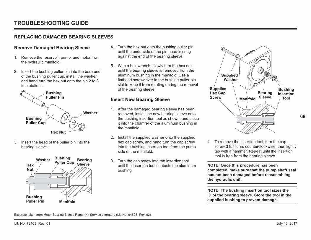
Lit. No. 72103, Rev. 01 July 15, 2017
68
4. To remove the insertion tool, turn the cap screw 3 full turns counterclockwise, then lightly tap with a hammer. Repeat until the insertion tool is free from the bearing sleeve.
NOTE: Once this procedure has been completed, make sure that the pump shaft seal has not been damaged before reassembling the hydraulic unit.
NOTE: The bushing insertion tool sizes the ID of the bearing sleeve. Store the tool in the supplied bushing to prevent damage.
4. Turn the hex nut onto the bushing puller pin until the underside of the pin head is snug against the end of the bearing sleeve.
5. With a box wrench, slowly turn the hex nut until the bearing sleeve is removed from the aluminum bushing in the manifold. Use a flathead screwdriver in the bushing puller pin slot to keep it from rotating during the removal of the bearing sleeve.
Insert New Bearing Sleeve
1. After the damaged bearing sleeve has been removed, install the new bearing sleeve onto the bushing insertion tool as shown, and place it into the chamfer of the aluminum bushing in the manifold.
2. Install the supplied washer onto the supplied hex cap screw, and hand turn the cap screw into the bushing insertion tool from the pump side of the manifold.
3. Turn the cap screw into the insertion tool until the insertion tool contacts the aluminum bushing.
Remove Damaged Bearing Sleeve
1. Remove the reservoir, pump, and motor from the hydraulic manifold.
2. Insert the bushing puller pin into the bore end of the bushing puller cup, install the washer, and hand turn the hex nut onto the pin 2 to 3 full rotations.
3. Insert the head of the puller pin into the bearing sleeve.
REPLACING DAMAGED BEARING SLEEVES
BushingPuller Pin
BushingPuller Cup
Hex Nut
Washer
Manifold
BushingPuller CupHex
Nut
Washer
BushingPuller Pin
BearingSleeve
TROUBLESHOOTING GUIDE
Excerpts taken from Motor Bearing Sleeve Repair Kit Service Literature (Lit. No. 64595, Rev. 02).
BushingInsertion
ToolBearingSleeve
SuppliedWasher
SuppliedHex CapScrew Manifold

Lit. No. 72103, Rev. 01 July 15, 2017
69
Pump Alignment
NOTE: The hydraulic pump may contain a .75" OD alignment ring that fits in a counter‑bore around the shaft. This pump alignment procedure is necessary only for hydraulic pumps that do not utilize this alignment ring (as in the illustration) or if the alignment ring has been lost.
1. After the new bearing sleeve has been inserted, install the pump and pump fasteners, but do not tighten them yet.
2. Insert the pump alignment tool into the bearing sleeve and over the pump shaft.
Manifold
PumpAlignment
Tool
BearingSleeve
Pump
TROUBLESHOOTING GUIDE
Excerpts taken from Motor Bearing Sleeve Repair Kit Service Literature (Lit. No. 64595, Rev. 02).
3. With the pump alignment tool in place, alternately tighten the pump fasteners to 150–160 in‑lb.
4. Remove the pump alignment tool.
NOTE: If the surface of the alignment tool is marred, it will damage the motor bearing sleeve. Store the tool in the supplied rubber tubing to prevent damage.

Lit. No. 72103, Rev. 01 July 15, 2017
70
A DIVISION OF DOUGLAS DYNAMICS, LLC
Copyright © 2017 Douglas Dynamics, LLC. All rights reserved. This material may not be reproduced or copied, in whole or in part, in any printed, mechanical, electronic, film or other distribution and storage media, without the written consent of Western Products. Authorization to photocopy items for internal or personal use by Western Products outlets or snowplow owner is granted.
Western Products reserves the right under its product improvement policy to change construction or design details and furnish equipment when so altered without reference to illustrations or specifications used. Western Products or the vehicle manufacturer may require or recommend optional equipment for snow removal. Do not exceed vehicle ratings with a snowplow. This product is manufactured under the following US patents: 7,400,058; 7,737,576; 9,200,418, and other patents pending. Western Products offers a limited warranty for all snowplows and accessories. See separately printed page for this important information. The following are registered (®) or unregistered (™) trademarks of Douglas Dynamics, LLC: FloStat®, IMPACT™, SECURITY GUARD™, WESTERN®.
Printed in U.S.A.
Western ProductsPO Box 245038Milwaukee, WI 53224-9538www.westernplows.com