Mfg. Processes Lab Manual...Welding: Perform welding utilizing the arc welding process. The ETME 216...
55
Version: 9 Revised 3/3/16 Mfg. Processes Lab Manual Manufacturing Processes Lab Manual ETME 216 & ETME 217 Dr. John R. Davis ScD Associate Teaching Professor Montana State University 2008
Transcript of Mfg. Processes Lab Manual...Welding: Perform welding utilizing the arc welding process. The ETME 216...
Version: 9 Revised 3/3/16 Mfg. Processes Lab Manual
Manufacturing Processes
Lab Manual
ETME 216 & ETME 217
Dr. John R. Davis ScD Associate Teaching Professor
Montana State University 2008

Version: 9 Mfg. Processes Lab Manual 1
Introduction Both the ETME 217 and ETME 216 labs are designed to provide hands-on experience with a variety of manufacturing processes. It is constructed to parallel the ETME 215 Manufacturing Processes lecture as closely as possible. Each experiment will be relatively simple in nature, but provide the student with a good understanding of the various processes from more then a theoretical viewpoint. Most of the experiments will show actual results against those calculated and provide the opportunity to examine any differences and conclude what may have happened. A combination of formal lab reports, lab summaries and lab memos will be the main deliverables for this course. For the ETME 217 lab, a variety of experiments will be covered. This lab will perform experiments in the following areas: Metal Casting: Constructing a sand casting mold, pouring an aluminum cast, and comparing the actual casting against calculate values. Plastic Injection Molding: Stabilize a plastic molding process with a given material. Determine the optimum temperature and pressure for producing quality parts. Power Metallurgy: Form parts from metallic powders, record and plot pressing data, perform destructives tests on sintered powder metal parts. Metrology: Perform precise validation techniques on both a part inspection and a random measurement. Material Removal: Perform various machining operations on both a milling machine and lathe. Welding: Perform welding utilizing the arc welding process. The ETME 216 Lab will cover many of the same experiments as the ETME 217 lab will with some additions in place of machining and welding. This lab will perform experiments in the following areas: Metal Casting: Constructing a sand casting mold, pouring an aluminum cast, and comparing the actual casting against calculate values. Plastic Injection Molding: Stabilize a plastic molding process with 2 different materials. Determine the optimum temperature and pressure for producing quality parts. Powder Metallurgy: Form parts from metallic powders, record and plot pressing data, perform destructives tests on sintered powder metal parts. Sheet Metal Forming: Determine and calculate bend allowances, develop a flat blank layout from an assembly print, transfer the layout to the sheet metal, cut and form to the desired shape, weld the shape and inspect. Turning Evaluation: Determine the outcome of adjusting variables during machining and calculate theoretical values to compare against measured values, and determine optimized settings Metrology: Perform precise validation techniques on both a part inspection and a random measurement. Also, learn various measurement techniques with various hand measuring tools.

Version: 9 Mfg. Processes Lab Manual 2
Table of Contents General Course Information ................................................................................................................ 3 ETME 217 Lab Course Outline ........................................................................................................... 4 ETME 216 Lab Course Outline ........................................................................................................... 5 Lab Reports, Summaries, and Memos ................................................................................................ 6
Lab Report Format .......................................................................................................................... 7 Lab Summary Format .................................................................................................................... 10 Lab Memo Format ......................................................................................................................... 13
Metal Casting Experiment: ETME 216 & ETME 217 ......................................................................... 14 Plastic Injection Molding Experiment: EMET 216 & ETME 217 ......................................................... 16 Powder Metallurgy Experiment: ETME 216 & ETME 217 .................................................................. 17 Metrology Experiment: ETME 216 & ETME 217 ................................................................................ 19 Material Removal Experiment: ETME 217 Only ................................................................................ 20 Sheet Metal Forming Experiment: ETME 216 Only ........................................................................... 22 Turning Optimization Experiment: ETME 216 Only ........................................................................... 23 Welding & Joining Technology Experiment: ETME 217 Only ............................................................ 25 Attachments ...................................................................................................................................... 27 Reference Materials .......................................................................................................................... 54

Version: 9 Mfg. Processes Lab Manual 3
General Course Information Prerequisites: ETME 215 – Manufacturing Processes (or currently enrolled) Goals/Objectives: The overall objective of the lab is to gain a practical understanding of various manufacturing processes in a hands-on environment. Lab notebooks will be maintained and formal reports, lab summaries, and lab memos will be generated reflecting an engineering experiment format focusing on the proper writing and reporting methods. Experiments and simulation of manufacturing processes related to topics covered in ETME 215 (Manufacturing Processes Course) will be set-up and performed. The lab projects will coincide with the ETME 215 course materials as closely as possible. Specific Objectives:
Develop a practical understanding of basic manufacturing processes and capabilities of each.
Set-up and conduct engineering experiments related to various manufacturing processes.
Maintain lab notebooks in an engineering format.
Generation of formal lab reports, lab summaries and memos reflecting experiments performed.
Enhance ability to determine data given and what information to find.
Learn to make engineering judgments.
Extend basic knowledge to solve manufacturing processes related problems.
Emphasize the problem solving process and application techniques.
Analyze date from experiments to performed and reach conclusions.
Require adherence to assignment deadlines.
Improve team working skills through group assignments. Lab Conduct & Attire: Students will conduct themselves in a productive manner at all times. Arrive on time and ready to participate in the experiments whether team or individual. Wear clothing that is protective and can get dirty. The follow clothing items are not allowed in the lab: Open toe shoes, shorts, skirts/dresses, etc. Anyone showing up wearing these items will not be allowed to participate in the lab session. GRADING: Lab Reports 30% Lab Summaries 30% Lab Memos 30% Lab Participation 10% TOTAL: 100% Participation is MANDATORY. If a lab is missed it is the responsibility of the student to attend another lab to make it up otherwise the grade for a team report or summary will be reduced accordingly. Formal reports will be done as a team where each member will receive the same grade with the opportunity for a re-write on the first one to improve your grade. You will have 2 weeks to complete them after the experiment is completed. Summaries will be done as a team where each member will receive the same grade. You will have 1 week to complete them after the experiment is completed. Memos will be done on an individual bases and will be due 1 week after the experiment is completed.
~ Reports, Summaries, and Memos will be docked 5 points per day for being turned in late ~

Version: 9 Mfg. Processes Lab Manual 4
ETME 217 Lab Course Outline Week Lab Deliverable 1 Spring Semester; No Lab Session. Fall Semester; Lab Meets 2 Introduction to Manufacturing Lab Safety 3 Metal Casting Experiment: Formal Report 4 Metal Casting Experiment (continued) 5 Plastic Injection Experiment: Summary 6 Powder Metal Experiment: Formal Report Casting Report Due 7 Powder Metal Experiment (continued) Plastics Summary Due 8 Material Removal Experiment: Memo 9 Material Removal Experiment (continued) Powder Report Due 10 Material Removal Experiment (continued) 11 Material Removal Experiment (continued) 12 Metrology: Inspection / Measurement: Summary Mach. Memo Due 13 Metrology: Inspection / Measurement (continued) 14 Welding Experiment (Arc Welding): Memo Metrology Summary Due 15 Make-up Week Welding Memo Due

Version: 9 Mfg. Processes Lab Manual 5
ETME 216 Lab Course Outline Week Lab Deliverable 1 Spring Semester; No Lab Session. Fall Semester; Lab Meets 2 Introduction to Manufacturing Lab Safety 3 Metal Casting Experiment: Formal Report 4 Metal Casting Experiment (continued) 5 Plastic Injection Experiment: Summary 6 Powder Metal Experiment: Formal Report Casting Report Due 7 Powder Metal Experiment (continued) Plastic Summary Due 8 Metal Forming Experiment: Memo 9 Metal Forming Experiment (continued) Powder Report Due 10 Metal Forming Experiment (continued) 11 Turning Experiment: Memo & Table Forming Memo Due 12 Metrology: Summary Turning Memo Due 13 Metrology (continued) 14 Metrology (continued) 15 Make-up Week Metrology Summary Due

Version: 9 Mfg. Processes Lab Manual 6
Lab Reports, Summaries, and Memos Writing is a critical part of the engineering field. Being able to produce high quality reports, summaries, and memos will be a major portion of your job. Knowing how to structure each and what information is required will assist you in future courses and in your working life as well. This lab will require writing formal reports, lab summaries, and lab memos to help you to understand how to write each. Each experiment during this lab will require either a formal lab report, lab summary, or lab memo of the experiment performed. Two formal reports will be required for both the Metal Casting and Powder Metallurgy experiments. The first formal report on Metal Casting will have the opportunity to perform a re-write to improve the grade. All formal reports and summaries need to be printed single sided, double spaced and using a size 11 font. For a lab memo, they need to be size 11 font, paragraph form and single spaced. For a formal report, lab summary, and lab memo be sure to use headings for the various sections. Each needs to have a heading with the pertinent information listed under it. Spelling and proper grammar needs to be utilized so make sure to proof read your material before submitting it to the instructor. Lab Formal Reports The formal lab reports for the experiments will be due 2 weeks after completion of the experiment. If the experiment runs for more then one week, it will include the work performed over the entire duration the experiment was conducted. These need to be VERY DETAILED and contain everything that was required to complete the experiment. In a formal lab report there needs to be enough information so the reader could conduct the experiment as you did and produce the same results. The majority of the information will be contained in the process and procedure section and there is no limit on the length. The grading criteria for formal reports can be found in attachment 1. Lab Summaries A summary will provide the reader with an overview of the experiments, buy not include the in-depth detail of a formal report. The challenge in writing a summary is to convey the important information to the reader so they get enough detail to understand what was performed and how. A summary should contain the section for the process and procedure of a length to 2 to 2 ½ pages would be about the proper length. In some instances, portions of a lab summary will become the abstract to a large formal report. The lab summaries for the experiments will be due 1 week after completion of the experiment. The grading criteria for lab summaries can be found in attachment 2. Lab Memos For composing a lab memo, it will be all on one page. The purpose of a memo is to state what the purpose of the lab experiment was, what was found during the experiment, and a conclusion. These are sent to management to update them on what was accomplished during the experiment. If more detail is desired by them, they can refer to either a lab summary or to the formal report that was written. The objective is to relay enough information in a memo and still keep it to one page in length. Each section (Purpose, Findings, & Conclusion) will be in paragraph form with a section heading for each. The grading criteria for lab summaries can be found in attachment 3.

Version: 9 Mfg. Processes Lab Manual 7
Lab Report Format
Cover Page
Separate page in the front of the report. The following information needs to be included on the cover
page.
Team Members
Submitted to
Date
Course & Section
Lab Topic
Introduction
The introduction informs the reader about the experiment that was conducted. For a formal report,
this is broken down into the 3 areas listed below.
Purpose of Experiment: What is the reason for conducting the experiment? Here, the rational
of the experiment is explained to the reader. This should be about a paragraph in length.
Problem being Addressed: What problems and issues is the experiment addressing? In this
section you will be addressing what the obstacles are which will be encountered during the
experiment that need to be overcome. This should be about a paragraph in length.
Scope of Experiment: What does the experiment encompass? Here you will outline exactly
what the experiment includes and what is not included. This informs the reader as to the
boundaries in which the experiment was conducted. This should be about a paragraph in
length.
Test & Evaluation
This should be the largest section of the report. Here you need to include enough detail in the
section below so the reader could read the report and have enough information and detail to be able
to repeat the experiment that you did and produce the same results.
Apparatus used: Here a list of EVERYTHING used in the experiment is compiled. Use bullets
to list them.
Process / Procedure / Sequence of Events: This will be the largest part of the report. There
has to be enough detail here so a person could read it, understand what was done and how,
and be able to repeat the experiment with no questions. For the 2 labs that you will be writing
a formal report for, this part should be 3 – 5 pages of information. Don’t write this in one big
paragraph. Use bullets or numbered lines for each sequence of the process.

Version: 9 Mfg. Processes Lab Manual 8
Findings
Here you will be listing what the actual findings of the experiment are. These could be dimensions,
visual observations, process observations, calculated information, etc. A detailed list of everything
found during the experiment should be contained in this section.
Data Gathered: List everything that you found during the experiment.
Interpretation & Results
This section will use the findings and conclude the results. Here from the findings listed in the
previous section, the overall results of the experiment are discussed. Also, the writer will offer their
interpretations of the results concluded. These are YOUR interpretations for the results achieved
during the experiment. This section should be between 2 – 4 paragraphs in length.
What happened and what you found: Discuss the results based on the experiment and what
your personal interpretations are for achieving the results.
Conclusions & Recommendations
These sections close the report. They need to also add value to the report and not just be something
written at the end. In the conclusion, a recap of the experiment is given to allow the reader to have a
summary of what was performed and the results found. For recommendations, this should outline
what would be performed differently if the same experiment were to be repeated. Both the
conclusion and recommendation section needs to be 2 – 4 paragraphs in length.
What is YOUR conclusion of the experiment: What is your personal summary of the
experiment discussing the process and results obtained? Also, what was learned during
conducting the experiment?
What do YOU recommend if the experiment were to be repeated: What would you perform
differently if this experiment were to be repeated? What suggestions would you make to
improve the experiment?
Attachments
Here, any information that supports the body of the report is included. This may include the items
listed below or any other information which the writer feels would add value to the report. Remember,
if information is listed as an attachment, it needs to be numbered. Also, if in the body of the report an
attachment is required to supply information, the writer MUST reference the attachment number in the
body.
Calculations: Any figures that needed to be derived in performing the experiment. These may
be performed to find expected values or to determine values from the experimental data.
Version: 9 Mfg. Processes Lab Manual 9
Data Sheets: A data sheet is either the original or a copy of the information that was written
down during the experiment. This shows the exact information that was collected from the
experiment and provides the reader the opportunity to view what the writer considered
important at the time the experiment was being conducted. These do not have to be neat and
orderly. Copies from your lab notebook are fine.
Figures & Graphs: In some experiments, charting data that was either collected or calculated
may be important. Charting provides the reader a visual understanding of what happened
during the experiment.
Drawings, Sketches & Pictures: These provide the reader the visual understanding as figures
and charts do. Digital pictures can help explain a lot when used in conjunction with the body
of a report. The same can be said for note book sketches and CAD drawings. The old saying
that a picture is worth a 1,000 words has a lot of merit to it. However, there still needs to be
enough written information in the body of the report to explain what the picture or drawing is
showing.
Reference Materials: If any information is utilized to complete the lab which comes from any
outside source it needs to be listed. This may be from the ETME 215 text book, other
reference book, or web based information. For this lab, just referencing the book, technical
manual, or web site is sufficient.
Anything Else Important
Version: 9 Mfg. Processes Lab Manual 10
Lab Summary Format
Cover Page
Separate page in the front of the report. The following information needs to be included on the cover
page.
Team Members
Submitted to
Date
Course & Section
Lab Topic
Introduction
The introduction informs the reader about the experiment that was conducted. For a lab summary,
this will only include the purpose that the experiment was conducted.
Purpose of Experiment: What is the reason for conducting the experiment? Here, the rational
of the experiment is explained to the reader. This should be about a paragraph in length.
Test & Evaluation
Unlike a formal report, this section will be shorter and contain far less detail. The intention here is to
provide the reader with enough information so they understand what was performed to complete the
experiment. The reader is not expected to be able to repeat the experiment from the information
provided, but be able to comprehend the process and what important features where required.
Apparatus used: Here a list of EVERYTHING used in the experiment is compiled. Use bullets to list
them.
Process / Procedure: Brief description of the process that was performed to conduct the experiment.
Here the challenge is to relay enough information so the reader can understand what was done and
how along with any critical points within the procedure. For a summary use paragraphs with indents
and not bulleted lines. This section should be between 2 – 21/2 pages in length.

Version: 9 Mfg. Processes Lab Manual 11
Findings
Here you will be listing what the actual findings of the experiment are. These can be dimensions,
visual observations, process observations, calculated information, etc. A detailed list of everything
found during the experiment should be contained in this section.
Data Gathered: List everything that you found during the experiment.
Conclusions
This section closes the summary. It needs to add value to the report and not just be something
written at the end. The conclusion is a recap of the experiment to allow the reader to have a
summary of what was performed and the results found.
What is YOUR conclusion of the experiment: What is your personal summary of the
experiment discussing the process and results obtained? Also, what was learned during
conducting the experiment?
Attachments
Here, any information that supports the body of the report is included. This may include the items
listed below or any other information which the writer feels would add value to the report. Remember,
if information is listed as an attachment, it needs to be numbered. Also, if in the body of the report an
attachment is required to supply information, the writer MUST reference the attachment number in the
body.
Calculations: Any figures that needed to be derived in performing the experiment. These may
be performed to find expected values or to determine values from the experimental data.
Data Sheets: A data sheet is either the original or a copy of the information that was written
down during the experiment. This shows the exact information that was collected from the
experiment and provides the reader the opportunity to view what the writer considered
important at the time the experiment was being conducted. These do not have to be neat and
orderly. Copies from your lab notebook are fine.
Figures & Graphs: In some experiments, charting data that was either collected or calculated
may be important. Charting provides the reader a visual understanding of what happened
during the experiment.
Drawings, Sketches & Pictures: These provide the reader the visual understanding as figures
and charts do. Digital pictures can help explain a lot when used in conjunction with the body
of a report. The same can be said for note book sketches and CAD drawings. The old saying
that a picture is worth a 1,000 words has a lot of merit to it. However, there still needs to be
enough written information in the body of the report to explain what the picture or drawing is
showing.

Version: 9 Mfg. Processes Lab Manual 12
Reference Materials: If any information is utilized to complete the lab which comes from any
outside source it needs to be listed. This may be from the ME 255 text book, other reference
book, or web based information. For this lab, just referencing the book, technical manual, or
web site is sufficient.
Anything Else Important

Version: 9 Mfg. Processes Lab Manual 13
Lab Memo Format
Heading (But don’t put the word “Heading” on the memo) For a lab memo, the heading needs to be at the top of the page in the format listed below. To: Instructor Name Date: XX/XX/XXXX From: Your Name Partners: Name 1 Name 2 Subject: Lab Title Name 3 Purpose What is the reason for conducting the experiment? Here, the rational of the experiment is explained
to the reader. This should be about a paragraph in length.
Findings Here you will be listing what the actual findings of the experiment are. These can be dimensions,
visual observations, process observations, calculate information, etc. A detailed list of everything
found during the experiment should be contained in this section. For a memo, this needs to be in
paragraph form and not a bullet list.
Conclusion This section closes the memo. It needs to add value to the report and not just be something written
at the end. The conclusion is a recap of the experiment to allow the reader to have a summary of
what was performed and the results found.
Note: Memos can be single spaced to get enough information on them. No attachments or pictures can be part of a memo.

Version: 9 Mfg. Processes Lab Manual 14
Metal Casting Experiment: ETME 216 & ETME 217
~ THIS IS A “2” LAB EXPERIMENT ~ Introduction: Sand casting is the process of placing a pattern with a shape of the desired part in sand to make an imprint, incorporating a gating system, filling the resulting cavity with molten metal, allowing the metal to cool until it solidifies, breaking away the sand mold, and removing the cast part. During the week, calculated values for the pour will be performed and ready to compare to the actual values that will be found the following week. During the fist lab period we will practice constructing the mold and document the process steps required. At the end of the lab the mold will be broken apart. The second lab period the mold will be reconstructed (this will take about 1/3 the amount of time) and the mold will be poured with aluminum. From there, the casting will be inspected and compared against the calculated values. Step 1: Mold Making
Measure all dimensions of the assigned pattern which will be used.
Mold Construction
o Rub parting agent on both sides of the bottom board.
o Assemble cope, drag, and bottom board.
o Pack sand into drag side first; Pack it tightly
o Flip over assembly, and then pack cope side; Pack it tightly.
o Cut appropriate sprue, vents, risers, gates, etc.
Step 2: Estimated Process Values
Calculate estimated process values. (See Attachment 4 for formulas)
o Flow Velocity (dependent on sprue size)
o Volumetric Flow Rate
o Mold Fill Time
o Part Shrinkage
Data Provided
o Solidification Shrinkage = 7.0%
o Solid Thermal Contraction = 5.6%
o Linear Shrinkage Value = 1.3%
Step 3: Part Fabrication
Melt aluminum in Mighty Mite Furnace (Performed by lab instructor)
Pour Aluminum
o Preheat ladle
o Immediately pour melted aluminum into ladle and into sand casting
o Pour remaining aluminum in the ladle back into the furnace

Version: 9 Mfg. Processes Lab Manual 15
Step 4: Part Inspection
Allow casting to cool outside and break off sand
Quench the casting in H2O tank
Clean casting with wire brush
Measure casting dimensions
o Compare to Estimated values
o Compare to Pattern dimensions
Clean-up workstation
~ Formal Lab Report Written by the Team Due 2 Weeks After Experiment Completion ~

Version: 9 Mfg. Processes Lab Manual 16
Plastic Injection Molding Experiment: EMET 216 & ETME 217 ~ THIS IS A “1” LAB EXPERIMENT ~
Introduction Injection molding is a process of molding solid plastic objects. It involves forcing molten plastics into a closed mold where the plastic solidifies into a usable product upon cooling. Each lab group is to utilize the injection molding equipment in the lab to manufacture a screwdriver and checker per the procedure listed below. Objective To observe the injection molding process and the yield of molded parts under various conditions and materials. The process will require several adjustments to establish the proper settings for each material being used in order to produce good parts in a repeatable process. Lab Procedure: Note: 2 different materials will be used. Polystyrene and polypropylene. Make sure you know the material that you’re using for the parts being manufactured. Adjustments will be made to the temperature and pressure used in the process. When making an adjustment, ONLY CHANGE 1 VARIABLE AT A TIME!!!! Phase I.
1. Plug the molding machine into the power supply 2. Turn heater on, set knob between medium and high, and allow time to warm up to at least
400O F 3. Set the air compressor to 40 psig. 4. Fill the hopper with suitable granulated plastic material. 5. Lightly spray silicone into the separated mold to prevent excess sticking of the molded
parts. 6. Clamp molds together and align under injection nozzle. Note: you only need to align the
molds right or left. 7. Push black ram actuating “In” and HOLD. This will force the cylindrical ram down and
force the molten plastic into the mold. Once the ram stops moving completely, release the button.
8. Repeat step #4 9. Release clamp and remove part from mold. 10. Inspect product and record the process information on the process establishment table (See Attachment 5 for process table)
Phase II. After inspecting the results, make a change to either the temp or pressure and repeat the process. Remember, only change one variable at a time. Phase III. Revise the temp or pressure settings until good parts are manufactured. A good part means that you will produce 3 acceptable parts in a row. Phase IV. Inspect each of the manufactured parts and assess quality of each.
~ Lab Summary Written by the Team Due 1 Week After Experiment Completion ~
Version: 9 Mfg. Processes Lab Manual 17
Powder Metallurgy Experiment: ETME 216 & ETME 217
~ THIS IS A “2” LAB EXPERIMENT ~ Introduction Powder Metallurgy is the science of producing product from metallic powders. The powders are compressed in a die set to produce a green part. In this stage the parts are extremely fragile and need to be handled with care. A secondary operation called sintering is used which heats the parts to about 70-80% of the melting temp of the material they are produced from. Once sintered, the parts will be come stable and have several properties of a solid material. Objective The lab has two main objectives. The first is to observe the effects of tonnage when compressing the powder into briquettes. A comparison of tonnage vs. thickness and diameter will be observed and recorded. The second is to perform a variety of destructive tests on sintered parts. They will be tested for tension, shear, compression, and formability. Lab Procedure (Part 1):
1. Weigh the graduated cylinder
2. Carefully pour the Brass powder into the clean & dry graduated cylinder until it measures the required amount. Tap the side of the cylinder gently until the powder settles down to a uniform volume. Determine and record the weight of the powder.
a. All parts will be 6ml b. Try to keep the weight of all powder as close as possible.
3. Measure the I.D. of the die your group is using.
4. Transfer the powder from the cylinder to the die set and compact per the workgroup’s required
tonnage (see below). Be sure to follow all shop safety precautions.
5. CAREFULLY remove the green compact from the die. Be sure to handle the green compact gently because it isn’t very strong.
6. Weight the green compact and determine any changes in weight.
7. Calculate the following: (See Attachment 6 for formulas)
a. Porosity b. Packing Factor
8. Record ALL DATA gathered from all 4 groups
9. Chart the data to conclude the lab findings
a. Thickness vs. Tonnage b. Porosity vs. Tonnage c. Packing Factor vs. Tonnage
Version: 9 Mfg. Processes Lab Manual 18
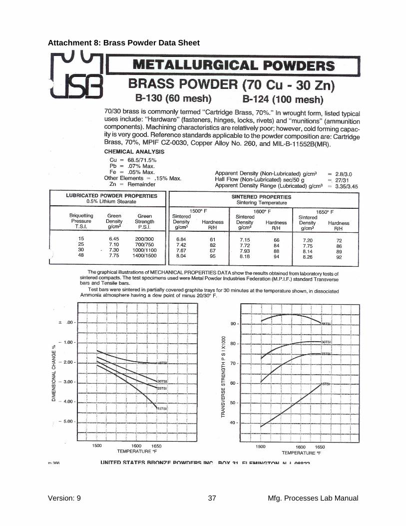
Workgroup Tonnage: Group A Group B 30 tons 35 tons 55 tons 55 tons Group C Group D 40 tons 45 tons 60 tons 65 tons Note: Chart all data on the data collection sheet in Attachment 7. Sintering: The brass compacts will be sintered for approximately 1.0 hour in a furnace at a temperature of 1600OF. They will be removed and allowed to cool to room temperature. Sintered parts will be ready for evaluation when we meet for the next lab session. (See Attachment 8 for brass powder data) Lab Procedure (Part 2):
1. Evaluate the sintered parts for visual effects from sintering: a. Color b. Flatness c. Diameter d. Thickness e. Surface Condition
2. Destructive Testing
a. Bending for shear force
i. 90o Break Press
ii. How much will it bend?
b. Machinability of Sintered Parts i. Milling Machine > Observe surface finish > Observe chips being produced > Compare them to chips from a solid material cut.
c. Roll Testing of Sintered Parts i. Record data from roll forming ii. Formability iii. % Reduction in Thickness
> Thickness vs. Length
d. Compression Testing of Sintered Parts i. Measure part thickness ii. Re-press at 70 tons iii. Re-measure thickness iv. Look for failure of parts.
~ Formal Lab Report Written by the Team Due 2 Weeks After Experiment Completion ~
Version: 9 Mfg. Processes Lab Manual 19
Metrology Experiment: ETME 216 & ETME 217
~ “2” LAB SESSIONS FOR ETME 217 ~ ~ “3” LAB SESSIONS FOR ETME 216 ~
Introduction Metrology is the science of precision measurement. This includes part dimensions, surface roughness, and material hardness to mention a few. A multitude of measuring devices will be utilized for this process, and they are far more accurate then the measuring equipment utilized in the actual production processes manufacturing the products. The difference between measurement and inspection will be covered along with performing both. Objective To gain knowledge of precision measurement and inspection in a lab environment. Precise readings of a variety of dimensions against the tolerances specified will be taken and recorded on a metrology report sheet. These reports are for conducting an inspection and will record the readings taken, compare them to the nominal dimensions, and record the amount of deviation from the tolerance ranges specified on the part prints. For performing measurements, at part will be provided with no print. A sketch will need to be made and from evaluations, the dimensions will be labeled on the sketch. (See Attachment 9 for Metrology Report Sheet). Lab Procedure:
1. Acquire a sample part to be measured and record the part number. 2. Visually examine the part against the part print to become acquainted with the part print views.
- Attachment 10 for ETME 217 print, Attachment 11 for ETME 216 print. 3. Make rough dimensional checks first with various measuring tools.
a. Dimensions b. Surface roughness
4. Begin the accurate measuring process.
a. Dimensions b. Surface roughness
5. Record all measurements taken on the Metrology Report Sheet. Equipment:
- Surface Plate - Surface Gage - Dial Indicator - Dial Height Indicator - Surface Roughness Testers. - 5” Sine Bar - Gage Blocks - 0 -1” Micrometer - Depth Micrometer - Optical Comparator
~ Lab Summary Written by the Team Due 1 Week After Experiment Completion ~
Version: 9 Mfg. Processes Lab Manual 20
Material Removal Experiment: ETME 217 Only
~ THIS IS A “4” LAB EXPERIMENT ~ Introduction Material removal involves machine processes of one type or another. It involves starting with a piece of material and then removing any un-wanted areas to create the desired shape and configuration desired. Three of the main processes utilized is turning, milling, and drilling. In turning, a part is shaped to a round configuration through various operations and set-up’s. Milling will create a part that is mainly square in nature utilizing various set-up’s, cutters, and operations. Drilling produces holes to various diameters utilizing drills and reamers. The material removal process will produce the most precise work, but is extremely time consuming and very waist full of material during the processing. Objective This lab is designed to give the student a “hands-on” knowledge of the metal removal process. It will include metal removal utilizing both in a milling and turning environment. The objective is to provide exposure to both processes and not to produce a perfect component part. A detailed part drawing will be provided for both a turned and milled part while the student will attempt to construct their component to the desired dimensions and tolerances. Lab Procedure For both milling and turning, safety is critical. Both of these machining processes can be extremely dangerous and cause major injuries. Listen carefully to the lab instructor on set-up and operating procedures. Always have the instructor check your machine set-up before starting to cut the material. Milling Procedure The milling experiment will be performed on the Bridgeport Universal milling machines. For this experiment, the student will become acquainted with face milling, setting up to establish 2 parallel surfaces, climb & conventional milling, establishing “X”, “Y”, & “Z” axis’s, pocketing, center drilling, drilling, and reaming. The dimensions and tolerances on the print provided will be attempted to be held, but the experiment grade will not be jeopardized if they are not. The print for this experiment can be found in attachment 13. The following tools will be utilized to complete this experiment:
- Face Milling Cutter - ½” 2 Flute End Mill - Edge Finder - Machinist Square - Parallel Bars - Center Drill - Drills: 0.250” & 0.46875” - 0.500” Reamer - Dial Calipers - Cutting Oil

Version: 9 Mfg. Processes Lab Manual 21
Turning Procedure The turning experiment will be performed on the various lathes in the lab. For this experiment the student will become acquainted with facing operations, diameter turning, taper turning, center drilling, drilling, and knurling operations and establishing “X” & “Z” axis’s. The dimensions and tolerances on the print provided will be attempted to be held, but the experiment grade will not be jeopardized if they are not. The print for this experiment can be found in attachment 12. The following tools will be utilized to complete this experiment:
- Left Handed Shouldering Tool - Knurling Tool - Center Drill - 0.250” Drill - Dial Calipers - 0 – 1” Micrometer - Cutting Oil
~ Lab Memo Written Individually Due 1 Week After Completion of the Experiment ~

Version: 9 Mfg. Processes Lab Manual 22
Sheet Metal Forming Experiment: ETME 216 Only
~ THIS IS A “3” LAB EXPERIMENT ~ Introduction Sheet metal work consists of cutting and forming of thin sheets of material. When a shape is punched out from a piece of material it is referred to as blanking. Bending sheet metal is known as a forming operation and can be performed in a variety of methods to achieve the desired results. When performing any sheet metal operations, the critical factors that need to be calculated are blanking force, bending force, and spring back. This process can at times be very wasteful of material, but the speed in which parts can be fabricated makes it very economical. Objective This lab is designed to gain an understanding of the sheet metal forming processes. It will require reading and understand an assembly part print of a formed sheet metal product. From that, a flat blank layout needs to be designed incorporating all the required bends for the finished product. The raw material will be laid-out from the flat blank design, cut and formed into the desired product. (See Attachment 14 for sheet metal assembly print) Procedure
1. Read and understand the assembly part print provided. 2. Develop a process plan for manufacturing the part.
a. This MUST be signed off and approved before proceeding b. See Attachment 15 for experiment process sheet
3. Design and develop a flat blank lay-out for the product See Attachment 16 for sheet metal formulas. 4. Lay-out the flat blank on the raw material 5. Make the required cuts to the sheet metal 6. Make the required bends to the cut sheet metal 7. Spot weld the folded joints 8. Inspect your part to the print dimensions 9. Conclude your findings / experiences
Equipment
1. 22” X 26” sheet of 18 gage low carbon cold rolled steel 2. Hand Shear 3. 90O Notch Press 4. Sheet-metal Scissors (hand operated) 5. 90O Break Press 6. Finger Break Press 7. Spot-Welder 8. Lay-out equipment
~ Lab Memo Written Individually Due 1 Week After Completion of the Experiment ~

Version: 9 Mfg. Processes Lab Manual 23
Turning Optimization Experiment: ETME 216 Only
~ THIS IS A “1” LAB EXPERIMENT ~ Introduction Machining is an extremely vestal process for creating a variety of component parts. There are a variety of metal removal processes available, each performing a specific function of material removal depending upon what the desired outcome requirements are. Several factors need to be considered when selecting a process such as part geometry, overall dimensions and tolerances, surface finish requirements, and material to be processed. The machining processes are capable of maintaining the closest tolerances and highest surface finishes of any manufacturing processes available, but are also the most time consuming and most wasteful of materials. When considering a process, one should be selected that will maintain the specified dimensions and tolerances, obtain the desired surface finishes, yet perform the machining in the least amount of time. Objective This lab is designed to expose the students to machining operation (Lathe Turning) to observe the machining time and surface finish obtained under a variety of feed rates. A part will be machined, timed, and measured to observe first-hand the results of the change in rates vs. the change in time and surface finishes. A variety of calculations will be performed and the gathered information will be charted to correlate the best possible scenario to achieve the desired results. Process
1. Measure the starting diameter of the material being processed. 2. Observe and time the machining on a lathe of the material under a variety of feeds. 3. Measure the surface finish obtained under each feed utilized. 4. Calculate the following for each machining condition (See Attachment 17 for Formulas)
a. Cutting Speed “v”
b. Feed Rate: “fr”
c. Machining Time: Tm
d. Material Removal Rate: MMR 5. Compile all measured and calculated information on the data sheet (See Attachment 18) 6. Analyze and chart data to determine the best scenario to achieve the desired results. 7. Determine the optimal Feed, Feed Rate, and Machining Time required to achieve the
following surface finishes
a. 95 Ra
b. 55 Ra
c. 35 Ra

Version: 9 Mfg. Processes Lab Manual 24
Data Material: Aluminum Rotational Speed “N”: 625 RPM
Depth of Cut “d” = Do-Df / 2
Length of Cut “L”: 6.000” Feed “f”:
1) 0.022 in/rev
2) 0.017 in/rev
3) 0.014 in/rev
4) 0.011 in/rev
5) 0.009 in/rev
6) 0.007 in/rev
7) 0.005 in/rev
8) 0.004 in/rev
9) 0.003 in/rev
10) 0.002 in/rev
Equipment Utilized Engine Lathe Left Hand Shouldering Tool Aluminum Bar Stock Cutting Oil (WD40) Safety Glasses Dial Calipers “V” Block Surface Plate Surface Testing Gage
~ Special Lab Memo Written Individually Due 1 Week After Completion of the Experiment ~

Version: 9 Mfg. Processes Lab Manual 25
Welding & Joining Technology Experiment: ETME 217 Only
~ THIS IS A “1” LAB EXPERIMENT ~ Introduction Welding is a material joining process where 2 or more parts are coalesced together at their contact surfaces. Fusion welding is the most common process used where heat is used to melt the base materials to achieve the coalescence. Another process is solid state welding where pressure or a combination of both pressure and heat as utilized to achieve the required coalescence. Welding produces a permanent joint and any disassembly will result in destroying the assembled parts. Also, in many cases a welded joint will be stronger then the base materials. Filler materials may or may not be utilized during the process which aid in the material flow of the base materials together and help to produce a stronger joint do to the addition of more material at the joining points. Objective The lab is designed to expose the student the welding process. The lab will consist of arch welding allowing for hands-on experience with being able to run beads and perform simple joining. This process will require using direct current and a consumable electrode to achieve the desired results. Welding Procedure In both arc welding and oxyacetylene welding enough heat needs to be generated to be able to melt the base materials and allow them to flow together to achieve a strong joint. Although the process is simple in nature, the art of welding takes a good amount of time to master. If there isn’t enough heat, the joint penetration will not be deep enough and the joint will fail. In the same token, if to much heat is applied the penetration will be too deep and the base materials will be greatly deformed at the joining point. Only through practice can a quality weld be produced with any welding process being utilized. Safety is critical in all welding processes. If something is not fully understood do not proceed without consulting the lab instructor. Also, the lab instructor must check your set-up’s before you begin to weld. Arc Welding Arc welding, or shielded metal arch welding (SMAW) utilizes a consumable electrode and high current to produce the required heat. It can be performed with either alternating current (AC) or direct current (DC). For this experiment we will be using DC at approximately 110 amps. The electrode will be hooked up to the positive line and the welding table will be negative. A 7018 electrode will be used and assembled to the holder. The electrode will be brought in contact with the work piece thus creating a short and produce the required heat to melt the base materials. Safety is critical and safety glasses, welding gloves, and a welding helmet need to be worn at all times while the arc is being produced and all safety curtains need to be closed. Arc welding produces both UV and Inferred light at the point of the arc and this will cause severe eye damage if exposed to the naked eye. Also, the work piece will become extremely hot during the process and needs to be handled with pliers. CAUTION: When performing arch welding, NEVER place the electrode on the welding table as this will produce an arch and is extremely dangerous. Always place the electrode on the hook located on

Version: 9 Mfg. Processes Lab Manual 26
the side of the welding booth. Also, NEVER sit down while performing arch welding. The spatter will fly and could land on your legs producing severe burns through your pants.
~ Lab Memo Written Individually Due 1 Week After Completion of the Experiment ~
Version: 9 Mfg. Processes Lab Manual 27
Attachments
Attachment 1: Formal Lab Report Scoring Criteria ............................................................................ 28 Attachment 2: Lab Summary Scoring Criteria ................................................................................... 29 Attachment 3: Lab Memo Scoring Criteria ......................................................................................... 30 Attachment 4: Cast Experiment Formulas ......................................................................................... 31 Attachment 5: Plastic Molding Process Establishment Table ............................................................ 32 Attachment 6: Powder Metallurgy Formulas ...................................................................................... 35 Attachment 7: Powder Metal Collection Data Sheet .......................................................................... 36 Attachment 8: Brass Powder Data Sheet .......................................................................................... 37 Attachment 9: Metrology Report Sheet ............................................................................................. 39 Attachment 10: ETME 217 Metrology Inspection Print ...................................................................... 42 Attachment 11: ETME 216 Metrology Inspection Print ...................................................................... 43 Attachment 12: Metrology Measurement Sketch ............................................................................... 44 Attachment 13: Turning Experiment Print .......................................................................................... 45 Attachment 14: Milling Experiment Print ............................................................................................ 46 Attachment 15: Sheet Metal Experiment Print ................................................................................... 47 Attachment 16: Sheet Metal Experiment Process Sheet ................................................................... 48 Attachment 17: Sheet Metal Experiment Formulas ........................................................................... 51 Attachment 18: Turning Experiment Formulas .................................................................................. 52 Attachment 19: Turning Experiment Data Table ................................................................................ 53
Version: 9 Mfg. Processes Lab Manual 28
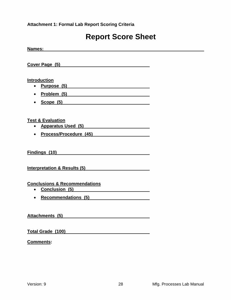
Attachment 1: Formal Lab Report Scoring Criteria
Report Score Sheet Names: Cover Page (5) Introduction
Purpose (5)
Problem (5)
Scope (5)
Test & Evaluation
Apparatus Used (5)
Process/Procedure (45)
Findings (10) Interpretation & Results (5) Conclusions & Recommendations
Conclusion (5)
Recommendations (5)
Attachments (5) Total Grade (100) Comments:

Version: 9 Mfg. Processes Lab Manual 29
Attachment 2: Lab Summary Scoring Criteria
Summary Score Sheet
Names: Cover Page (5) Introduction (10) Test & Evaluation
Apparatus Used (10)
Process/Procedure (50)
Findings (10) Conclusion (10) Attachments (5) Total Grade (100) Comments:

Version: 9 Mfg. Processes Lab Manual 30
Attachment 3: Lab Memo Scoring Criteria
Memo Score Sheet
Name: Memo Heading (10) Experiment Purpose (30) Findings (30) Conclusion (30) Total Grade (100) Comments:

Version: 9 Mfg. Processes Lab Manual 31
Attachment 4: Cast Experiment Formulas Flow Velocity
ghv 2
g = Gravitational Acceleration 981 cm/sec2 386 in/sec2 Volumetric Flow Rate
nn AvAvAvQ ...2211
v = Flow Velocity A = Cross sectional area of the liquid Mold Fill Time
QVMFT
V = Mold Volume Q = Volumetric Flow Rate Part Shrinkage (3 Dimensional)
3/1)]1)(1[( STCSSSv
Material Solidification Solid Thermal Type Shrinkage % Contraction %
Aluminum 7.0 % 5.6 % Al Alloy 7.0 % 5.0 % Gray Cast Iron 1.8 % 3.0 % Gray Cast Iron, High C 0.0 % 3.0 % Low C Cast Steel 3.0 % 7.2 % Copper 4.5 % 7.5 % Bronze (Cu-Sn) 5.5 % 6.0 %

Version: 9 Mfg. Processes Lab Manual 32
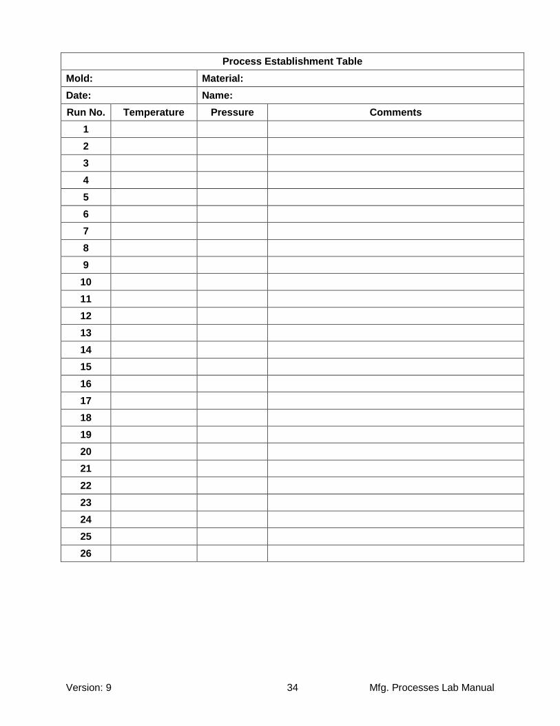
Attachment 5: Plastic Molding Process Establishment Table
Process Establishment Table
Mold: Material:
Date: Name:
Run No. Temperature Pressure Comments
1
2
3
4
5
6
7
8
9
10
11
12
13
14
15
16
17
18
19
20
21
22
23
24
25
26

Version: 9 Mfg. Processes Lab Manual 33
Process Establishment Table
Mold: Material:
Date: Name:
Run No. Temperature Pressure Comments
1
2
3
4
5
6
7
8
9
10
11
12
13
14
15
16
17
18
19
20
21
22
23
24
25
26
Version: 9 Mfg. Processes Lab Manual 34
Process Establishment Table
Mold: Material:
Date: Name:
Run No. Temperature Pressure Comments
1
2
3
4
5
6
7
8
9
10
11
12
13
14
15
16
17
18
19
20
21
22
23
24
25
26

Version: 9 Mfg. Processes Lab Manual 35
Attachment 6: Powder Metallurgy Formulas Packing Factor
PF = Bulk Density
/ True Density
PF = True Specific Volume
/ Bulk Specific Volume
PF = Weight of PM Part / Weight of Solid Part
Part Packing Factor
Packing Factor = Volume Weight of Briquette
/ Volume Weight of Solid
Porosity Porosity = 1 - Packing Factor

Version: 9 Mfg. Processes Lab Manual 36
Attachment 7: Powder Metal Collection Data Sheet
ETME 217 & ETME 216 Lab
Powder Metal Experiment
Data Sheet
Die Die Press Powder Part Part Part Comments
Letter I.D. Tonnage Weight Thickness Dia. Weight
30
35
40
45
50
55
60
65
Version: 9 Mfg. Processes Lab Manual 37
Attachment 8: Brass Powder Data Sheet

Version: 9 Mfg. Processes Lab Manual 38

Version: 9 Mfg. Processes Lab Manual 39
Attachment 9: Metrology Report Sheet
Part # : Inspectors :
Date :
Step Dimension Tolerance Reading Out of Range Comments
+ +
- -
+ +
- -
+ +
- -
+ +
- -
+ +
- -
+ +
- -
+ +
- -
+ +
- -
+ +
- -
+ +
- -
+ +
- -
+ +
- -
+ +
- -
+ +
- -
+ +
- -
+ +
- -
+ +
- -
+ +
- -
+ +
- -
+ +
- -
+ +
- -
+ +
- -
+ +
- -
+ +
- -
+ +
- -
+ +
- -
+ +
- -
D
C
F
E
H
G
K
J
M
L
O
N
Q
P
S
R
U
T
W
V
X
Metrology Report Sheet
B
A
AA
Y
Z
AB

Version: 9 Mfg. Processes Lab Manual 40
Part # : Inspectors :
Date :
Step Dimension Tolerance Reading Out of Range Comments
+ +
- -
+ +
- -
+ +
- -
+ +
- -
+ +
- -
+ +
- -
+ +
- -
+ +
- -
+ +
- -
+ +
- -
+ +
- -
+ +
- -
+ +
- -
+ +
- -
+ +
- -
+ +
- -
+ +
- -
+ +
- -
+ +
- -
+ +
- -
+ +
- -
+ +
- -
+ +
- -
+ +
- -
+ +
- -
+ +
- -
+ +
- -
D
C
F
E
H
G
K
J
M
L
O
N
Q
P
S
R
U
T
W
V
X
Metrology Report Sheet
B
A
AA
Y
Z
AB

Version: 9 Mfg. Processes Lab Manual 41
Part # : Inspectors :
Date :
Step Dimension Tolerance Reading Out of Range Comments
+ +
- -
+ +
- -
+ +
- -
+ +
- -
+ +
- -
+ +
- -
+ +
- -
+ +
- -
+ +
- -
+ +
- -
+ +
- -
+ +
- -
+ +
- -
+ +
- -
+ +
- -
+ +
- -
+ +
- -
+ +
- -
+ +
- -
+ +
- -
+ +
- -
+ +
- -
+ +
- -
+ +
- -
+ +
- -
+ +
- -
+ +
- -
D
C
F
E
H
G
K
J
M
L
O
N
Q
P
S
R
U
T
W
V
X
Metrology Report Sheet
B
A
AA
Y
Z
AB

Version: 9 Mfg. Processes Lab Manual 42
Attachment 10: ETME 217 Metrology Inspection Print
0.5
00
+0
.00
1
-0.0
01
0.6
88
+0.0
01
-0. 0
01
0.2
50
+0. 0
02
- 0.0
00
0.5
00
+0.0
02
- 0.0
00
1.6
25
+0.0
02
- 0. 0
02
1.3
75
+0
. 00
2
- 0.0
02
1.4
50
+0. 0
02
- 0.0
02
0.3
00
+0.0
25
-0. 0
25
20
O
+ 0
O, 3
0'
- 0
O, 3
0'
Me
tro
log
y L
ab
ET
ME
21
7
F
G D
E
C
BH
J
A
0.4
37
5 D
ia.
K+0. 0
00
5
- 0.0
00
5F
latn
es
s 0
.00
1
Su
rfa
ce
Ro
ug
hn
es
s3
2
16
L, M
, N
P, Q
, R

Version: 9 Mfg. Processes Lab Manual 43
Attachment 11: ETME 216 Metrology Inspection Print
1.6
25
+0
.00
3
-0. 0
05
1.8
75
+0
. 00
4
- 0.0
04
0.3
75
+0
. 00
5
-0. 0
00
1.8
13
+0
.00
2
-0.0
03
0.6
25
+0
. 00
3
- 0.0
03
0.6
25
+0
. 00
3
-0. 0
03
0.6
25
+0
. 00
3
-0. 0
03
0.7
50
+0
. 00
1
-0. 0
01
0.5
00
+0
. 00
2
- 0.0
02
15
O
50
O
0.1
50
+0
.00
2
- 0.0
02
+0
O, 3
0'
- 0O,
0'
+0
O, 3
0'
- 0O,
0'
0.3
75
Dia
.
0.5
00
Dia
.
+0
.00
05
- 0.0
00
5
+0
. 00
05
- 0.0
00
5
A
BC
H
D E
FG
LK
J
M
N
O
Fla
tne
ss
0.0
01
Su
rfa
ce
Ro
ug
hn
es
s3
2
16
Me
tro
log
y L
ab
ET
ME
21
6
P, Q
, R
S, T
, U

Version: 9 Mfg. Processes Lab Manual 44
Attachment 12: Metrology Measurement Sketch
A
BC
D
E
FG
H
JK
LM
NO

Version: 9 Mfg. Processes Lab Manual 45
Attachment 13: Turning Experiment Print
5.0
0"
3.0
0"
1.3
75"
1.0
0"
0.7
5
0.3
74
0.3
69
Dia
.
0.5
00" D
ia.
0.7
5" D
ia.
15
O
X-H
atc
h K
nu
rl0
.25
" D
ia.
Dri
lle
d .
07
5" D
ee
p
0.1
25
ET
ME
21
7 T
urn
ing
Pro
jec
t
Mate
rial:
Alu
min
um
To
lera
nces
X.X
X :
± 0
.01
0
X.X
XX
: ±
0.0
05

Version: 9 Mfg. Processes Lab Manual 46
Attachment 14: Milling Experiment Print
1.5
00 + 0
.01
0
- 0.0
00
0.5
00
± 0
.00
5
1.5
0 ± 0
.01
0
1.5
0 ± 0
.01
0
1.3
75
± 0
.00
5
0.1
25
± 0
.00
5
0.7
50
± 0
.00
5
0.7
50
± 0
.00
5
0.5
00
± 0
.00
5
Ty
p (4
)
0.2
50 R
ad
Ty
p (4
)
0.1
25
± 0
.00
5
ET
ME
217
Millin
g P
roje
ct
0.3
75 D
ia. R
eam

Version: 9 Mfg. Processes Lab Manual 47
Attachment 15: Sheet Metal Experiment Print
12
.00
± 0
.09
4
8.0
0 ± 0
.09
4
1.0
0 T
yp
(4)
± 0
.09
4
6.0
0 ± 0
.09
4
Sp
ot W
eld
(3) P
er T
ab
ET
ME
21
6
Sh
ee
t Me
tal
Prin
t

Version: 9 Mfg. Processes Lab Manual 48
Attachment 16: Sheet Metal Experiment Process Sheet
Sheet Metal Experiment Process Plan Oper Description Tooling
10
20
30
40
50
60
70
80
90
100
110
120
130
140
150
160
170
180
190
200

Version: 9 Mfg. Processes Lab Manual 49
Sheet Metal Experiment Process Plan Oper Description Tooling
10
20
30
40
50
60
70
80
90
100
110
120
130
140
150
160
170
180
190
200

Version: 9 Mfg. Processes Lab Manual 50
Sheet Metal Experiment Process Plan Oper Description Tooling
10
20
30
40
50
60
70
80
90
100
110
120
130
140
150
160
170
180
190
200
Version: 9 Mfg. Processes Lab Manual 51
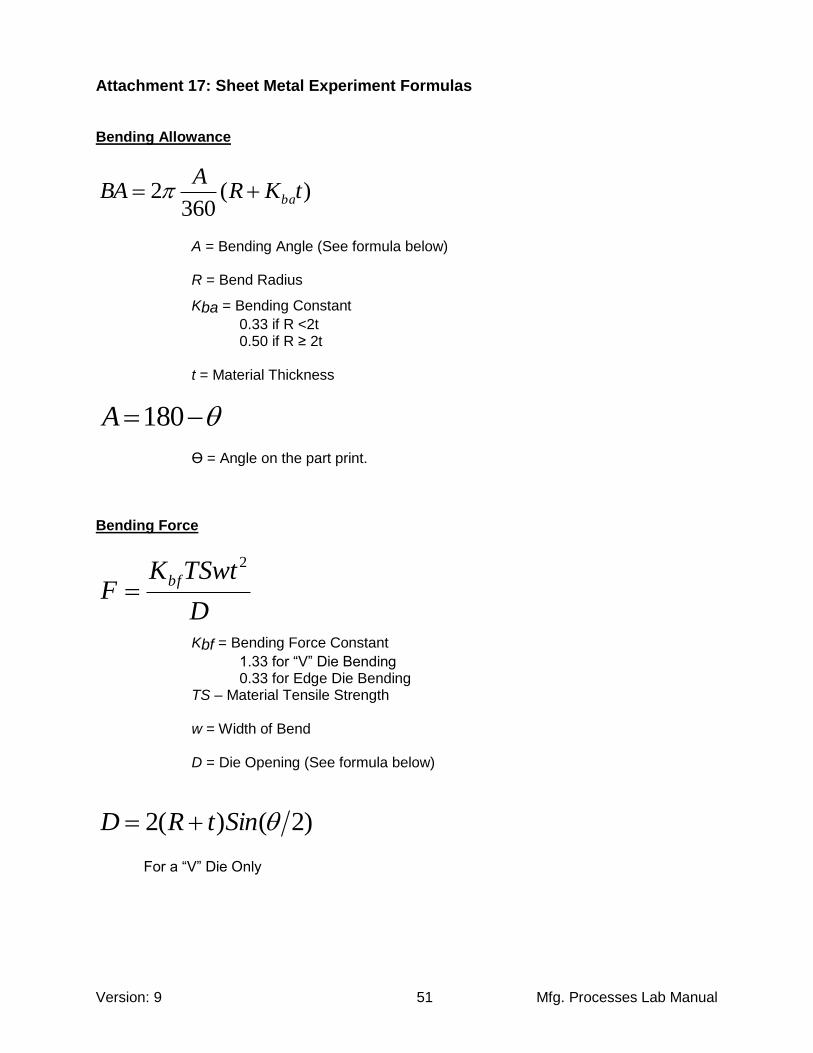
Attachment 17: Sheet Metal Experiment Formulas Bending Allowance
)(360
2 tKRA
BA ba
A = Bending Angle (See formula below) R = Bend Radius
Kba = Bending Constant
0.33 if R <2t 0.50 if R ≥ 2t t = Material Thickness
180A
Ө = Angle on the part print. Bending Force
D
TSwtKF
bf
2
Kbf = Bending Force Constant
1.33 for “V” Die Bending 0.33 for Edge Die Bending TS – Material Tensile Strength w = Width of Bend D = Die Opening (See formula below)
)2()(2 SintRD
For a “V” Die Only

Version: 9 Mfg. Processes Lab Manual 52
Attachment 18: Turning Experiment Formulas Rotational Speed
Do
vN
N = Rotational Speed: RPM
v = Cutting Speed: in/min
Do = Original Diameter: inches Feed Rate
Nffr
fr = Feed Rate: in/min
f = Feed: in/rev
Machining Time
fr
LTm
Tm = Machining Time: minutes
L = Length of Cut: inches Material Removal Rate
vfdMRR
MRR = Material Removal Rate: in3/min
d = Depth of Cut: inches

Version: 9 Mfg. Processes Lab Manual 53
Attachment 19: Turning Experiment Data Table
Name: Date:
Run f d L Do Ra fr v Tm MRR
1 0.022 6.000
2 0.017 6.000
3 0.014 6.000
4 0.011 6.000
5 0.009 6.000
6 0.007 6.000
7 0.005 6.000
8 0.004 6.000
9 0.003 6.000
10 0.002 6.000
Run Ra1 Ra2 Ra3 Ra4 Ra5 AVG
1
2
3
4
5
6
7
8
9
10
ETME 216 Turning Experiment Data Sheet

Version: 9 Mfg. Processes Lab Manual 54
Reference Materials Davis, J. 2015. Manufacturing Principles and Concepts; Production Fabrication Technology & Techniques. Great River Learning - Main Reference Book & Text Book for ETME 215 Groover, M. 2010. Fundamentals of Modern Manufacturing 4th Edition. Hoboken, NJ: Wiley. Kalpakjian, S / Schmid, S. 2006. Manufacturing Engineering and Technology 5th Edition. Upper Saddle River, NJ. Pearson Prentice Hall Le Grand, R. 1955. American Machinist’s Handbook. New York, NY. McGraw-Hill - Later Editions are Acceptable and Recommended. Wilson, F. 1959. Tool Engineers Handbook 2nd Edition. New York, NY. McGraw-Hill - Later Editions are Acceptable and Recommended. Brady, G. 1971. Materials Handbook 10th Edition. New York, NY. McGraw-Hill - Later Editions are Acceptable and Recommended.