MEWOURNE. VICTORI · MEWOURNE. VICTORI STRUCTURES NOTE 40 THE USE OF INTERFERENCE-FIT BOLTS OR...
56
ARL-SRU -NOT,-490 AR-oo2-973 , DEPARTMENT OF DEFENCE WNW DEFENCE SCIENCE AND TECHNOLOGY ORGANISATION AERONAUTICAL RESEARCH LABORATORIES a MEWOURNE. VICTORI STRUCTURES NOTE 40 THE USE OF INTERFERENCE-FIT BOLTS OR BUSHES AND HOLE COLD EXPANSION FOR INCREASING THE FATIGUE LIFE OF THICK-SECTION ALUMINIUM ALLOY BOLTED JOINTS by J. Y. MANN; A. S. MACHIN; W. F. LUPSON and R. A. PELL ITHE UNIT.iO STATES NATlONAL TECHNRICAL INFORMATION SYIOE 1S AUTH3RISED TO Approved for PNblic Release SJU 14194) A ©m COMNONWEATH Of AAJSrAUA 1983 ( 84 06 14 007
Transcript of MEWOURNE. VICTORI · MEWOURNE. VICTORI STRUCTURES NOTE 40 THE USE OF INTERFERENCE-FIT BOLTS OR...
ARL-SRU -NOT,-490 AR-oo2-973
, DEPARTMENT OF DEFENCEWNW DEFENCE SCIENCE AND TECHNOLOGY ORGANISATION
AERONAUTICAL RESEARCH LABORATORIESa MEWOURNE. VICTORI
STRUCTURES NOTE 40
THE USE OF INTERFERENCE-FIT BOLTS OR BUSHESAND HOLE COLD EXPANSION FOR INCREASING
THE FATIGUE LIFE OF THICK-SECTIONALUMINIUM ALLOY BOLTED JOINTS
by
J. Y. MANN; A. S. MACHIN; W. F. LUPSON
and R. A. PELLITHE UNIT.iO STATES NATlONALTECHNRICAL INFORMATION SYIOE1S AUTH3RISED TO
Approved for PNblic Release
SJUN 14194)A
©m COMNONWEATH Of AAJSrAUA 1983
( 84 06 14 007
ARCCB-973
DEPARTMENT OF DEFENCEDEFENCE SCIENCE AND TECHNOLOGY ORGANISATION
AERONAUTICAL RESEARCH LABORATORIES
STRUCTURES NOTE 490
THE USE OF INTERFERENCE-FIT BOLTS OR BUSHES
AND HOLE COLD EXPANSION FOR INCREASINGTHE FATIGUE LIFE OF THICK-SECTION
ALUMINIUM ALLOY BOLTED JOINTS
by
J. Y. MANN; A. S. MACHIN; W. F. LUPSON
and R. A. PELL
( SUMMARYThe detection of fatigue cracks at bolt holes in the main spar of the Mirage III wing
during full-scale fatigue tests led to a requirement for refurbishment procedures to extendthe fatigue lives at a number of critical locations. One of these, which is covered by thisinvestigation, was the spar lower front flange. Flight-by-flight fatigue tests have beencarried out to determine the relative fatigue performance of aluminium alloy bolted jointspecimens of 28 mm thickness incorporating close-fit bolts, interference-fit bolts (0.4%),hole cold-expansion (3 %), interference-fit steel bushes (0.3 %) and a combination of cold-expansion and interference-fit bushes. -
Compared with joints assembled with close-fit bolts in reamed holes, the ratios oflives of specimens incorporating ins&ference-fit bolts, interference-fit bushes and cold-expanded bolt holes were about 9:1, 5:1 and 3:1 respectively. Furthermore, specimenswith holes cold-expanded followed by the installation of interference-fit bushes resulted ina greater fatigue life than with interference-fit bushes alone.
_ Fractographic measurements of crack development from the bores of holes in specimensincorporating close-fit bolts in non cold-expanded (reamed) and cold-expanded holes clearlyindicated much slower fatigue crack propagation rates from the cold-expanded holes untilthe crack length was close to the nominal region of transition from the residual compressiveto tensile stress zone around the cold-expanded holes.
Fatigue tests on cold-expanded hole specimens at different spectrum scaling factorsindicated that, under the loading sequence used, each 10% increase in stress reduced thelife to about half that at the lower stress level.
It was concluded that if the refurbishmikrequirement involved the enlargement ofbolt holes to remove fatigue cracks and also 1he subsequent periodic non-destructiveinspection of the holes in service (which would be difficult if interference-fit bolts were Wdthen the use of interference-fit bushes either alone or In combination with hole cold-expnlomashould enable a satisfactory extension in fatigue life to be achieved for the detail of interestin the structure.
0 COMMONWEALTH OF AUSTRALIA 1983
POSTAL ADDRESS: Director, Aeronautical Research Laboratories,Box 4331, P.O., Melbourne, Victoria, 3001, Australia
,J4
CONTENTSPap No.
1. INTRODUCTION I
2. TEST SPECIMENS AND FATIGUE LOADING CONDITIONS 1
3. FATIGUE TESTING PROGRAM AND RESULTS 2
4. FATIGI A FRACTURES 4
5. FATIGUE RACK PROPAGATION RATES 5
6. STATIC FAILING LOADS OF SPECIMENS
7. DISCUSSION 6
& CONCLUSIONS 8
ACKNOWLEDGEMENTS 9
REFERENCES
GROSS AREAAPPENDIX 1-RATIOS GROSS AREA
NETW AREA
APPENDIX 2-DERIVATION OF TEST STRESSES
APPENDIX 3-SPECIMEN MANUFACTURE AND ASSEMBLY
TABLES
FIGURES
DISTRIBUTION For
DOCUMENT CONTROL DATA C . t, *
.q . ,
.0. -.. . ..

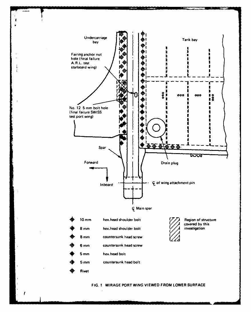
1. INTRODUCTIONFull-scale flight-by-flight fatigue tests on the structure of the Mirage III fighter aircraft
have been carried out at the Aeronautical Research Laboratories (ARL) and the EidgendssischesFlugzeugwerk (F + W) Switzerland. The Australian wing fatigue test was terminated by a cata-strophic failure which originated at the bottom of a blind hole in the lower flange of the mainspar, while in the Swiss test the final failure also originated at the lower surface of the main sparof the wing, but at a front flange bolt hole. The two failure locations are shown in Fig. 1, and aredescribed in detail in References I and 2. In addition, fatigue cracks were identified at a numberof other locations in the wing structure (Ref. 3).
Because of a requirement to extend the life-of-type of the Mirage Ill, several investigationswere undertaken at ARL to explore methods for improving the fatigue lives of portions of themain wing spar where cracks had been detected either in the full-scale fatigue tests or in service.Some of the results of these investigations-dealing with the inboard section of the rear lowerflange of the spar-have already been published (Refs 4, 5, 6).
The present investigation relates to the lower front flange of the spar at a position corres-ponding to the failure location in the spar during the Swiss test (Fig. 1). Unlike the rear flange(where clearance-fit fasteners are installed) the front flange incorporates a series of 5 mm diameterinterference-fit fasteners to secure the wing skin to the spar. Although interference-fit fastenerscan provide significant improvements in fatigue life (Refs 7, 8), the maintenance of accuratehole sizing and bolt dimensions are essential if the full benefits are to be realised. With the smalldiameter (5 mm) bolts and relatively long holes (30 mm) in the Mirage front flange, somedifficulties could have been expected in consistently obtaining the specified interferences (0.4 to0.8%).
As a result of the information derived from tests on specimens representing the inboardsection of the rear flange (Refs 5, 6), the fatigue life improvement techniques selected for thepresent investigation were cold-expansion of the bolt holes, the use of interference-fit steelbushes in bolt holes, and a combination of the two.
2. TEST SPECIMENS AND FATIGUE LOADING CONDITIONS
The main spar of the Mirage III is a large forging in aluminium alloy to the French Speci-fication A-U4SG (equivalent to the American alloy 2014 which is covered by SpecificationQQ-A-255a). As inadequate quantities of A-U4SG were available at the time, the test specimensused in this investigation were made from an equivalent British alloy (B.S. L168) suppliedin the form of 63.5 mm x 31 -75 mm extruded bars. Specification values covering the tensileproperties and chemical composition for the two alloys together with those derived from testson the particular batch of material used (laboratory code GR) are given in Table 1.
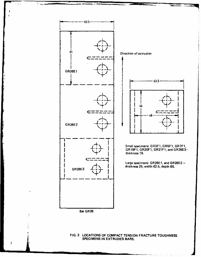
Figure 2 illustrates the general type of low-shear-load-transfer bolted joint fatigue specimenused in this investigation. As shown it represents the detail at the 12th to 16th bolt holes alongthe front flange, the thickness of the test section (28 mm) corresponding to the nominal thicknessof the flange at the 12th bolt hole. Tensile test specimens were taken from broken fatiguespecimens. All fatigue and tension specimens had their longitudinal axes parallel to the directionof extrusion. Compact tension fracture toughness specimens (thickness 25 mm and 19 mm)were taken from offcuts of the extrusion at the positions shown in Fig. 3. The relevant testresults are also given in Table I.
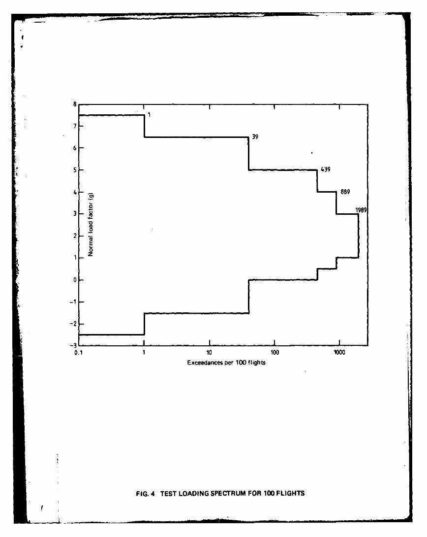
The fatigue load spectrum (Fig. 4) adopted for this investigation was a simplified version(derived by Avions Marcel Dassault-AMD) of the Swiss Mirage fulM-scale wing test spectrum.It was transformed into a 100-flight load sequence, the breakdown of this sequence into fourdifferent flight types (A', A, and C) being iven in FigS 5; and was identical to that used for
tI
the previous fatigue tests (Refs 5, 6) on rear flange specimens. Cycles of +6.5 g/- -5 g and+ 7.5 g/-2.5 g (a total of 39 cycles in 100 flights) were applied at a cyclic frequency of 1 Hz,whereas the remaining 1950 cycles per 100 flights were at 3 Hz. All fatigue tests were carriedout in a Tinius-Olsen servo-controlled electro-hydraulic fatigue machine, the 100-flight loadsequence being achieved using an EMR Model 1641 programmable function generator con-trolled by a punched tape and operating in sine wave mode.
Fatigue loads on most of the test specimens were derived on the basis that + 75 g corres-ponded to a gross area stress* (not including the skin plates) of 235 MPa (34,100 psi), andthat there was a linear stress/g relationship, i.e. the I g gross area stress was 31.3 MPa (4550 psi).Details relating to the derivation of these stresses are given in Appendix 2. In order to determinethe effects on fatigue life of increasing and reducing the magnitudes of the stress levels in thesequence, specimens in one of the cold-expanded hole test series were tested with all stressesscaled by factors of 1 25 and 0.85 relative to the remainder of the series, i.e. at + 7.5 g thecorresponding stresses were 294 MPa (42,630 psi) and 200 MPa (28,900 psi) respectively.
3. FATIGUE TESTING PROGRAM AND RESULTS
The selection of potential life-enhancement systems for the front flange of the Mirage wingmain spar was governed by the requirements that: (i) any existing fatigue cracks should be removedby reaming the holes and thus increa.'ng their diameters and (ii) that refurbished holes should bereadily inspectable in service (which wculd preclude the continued use of interference-fit bolts).Of the various refurbishment options available, cold-expansion of the bolt holes and the use ofinterference-fit steel bushes were considered to be the most promising. Both the hole cold-expan-sion and interference-fit bolt/bush systems for fatigue life eniancement depend on the intro-duction of residual stresses into the material surrounding the hole. Their application to aircraftstructural joints has recently been reviewed by Mann and Jost (Ref. 10).
Several series of tests (totalling 39 specimens) were carried out using the following com-binations of holes and fasteners. Details relating to specimen manufacture and assembly aregiven in Appendix 3.(A) 5 mm straight-shank interference-fit bolts. This series corresponded to the original structuraldetail and was used as a datum for comparing the effectiveness of the other test conditions.Bolt holes in the specimens were reamed to very close tolerances to accept bolts with nominally0.4 % to 0.8% interference. However, because of practical difficulties associated with bulgingof the bolts which prevented those providing the higher interference from being fully insertedin the holes, the maximum value was maintained at about 0"4 % by careful hole sizing and selec-tion of bolts of the appropriate diameter. The individual bolt insertion forces are given inAppendix 3.t For these specimens (excluding GRIDt) the average bolt insertion force was10720 N (2410 pounds) and standard deviation 3520 N (792 pounds). For degrees of interferenceup to the maximum interference used in this investigation (0-4% in the case of interference-fitbolts) the maximum hoop stresses introduced into the aluminium alloy adjacent to the holesshould (theoretically) not have caused yielding of the material. Their magnitudes for the variousinterference-fit conditioni are given in Table 2.
Fatigue test results for this series of 'control' specimens are given in Table 3(A). Thesignificance (for all test series) of the life to failure being associated predominantly with flight 42is that this flight contaim the maximum load range (+ 7.5 g to -2.5 g) which occurs only onceis uh 0-fht seqwnce.
* The ratio of gros/nett areas at the bolt hole sections in the 'control' and refurbishmentconfigurations are given in Appendix I. For this material the modulus of elasticity was taken as73100 MPa (10.6x 0s psi).
t The bolt hole identification system, (I) to (5), adopted in this investigation is indicated onFgW 2.
$ GRID was the first specimen with interference-fit bolts and it was intended that they should4 have 0.6%. to 0.8% interference. The high bush insertion forces reflect the difficulty in bolt
inrtion which was eliminated by adopting an interkrence of 0.4%.
2
f

(D) 5 mm straight-shank close-fit bolts. An examination of the 5 mm front flange bolts and boltholes in spars from s eral crashed aircraft indicated that the degree of interference of some boltsmight have been much less than the nominal minimum value of 0 4%. Since fatigue perforaancewould be expected to decrease with reductions in the degree of interference, a series of tests wasconducted to assess the behaviour of specimens incorporating close-fit bolts with a clearance of0.016 to 0.034 mm. The results of tests involving 5 mm close-fit bolts in reamed holes are givenin Table 3(B).(C) Cold-expanded holes. Cold-expansion of bolt holes using the Boeing Split-Sleeve process
(Ref. 11) was investigated during the two complementary investigations (Refs 5, 6) into extendingthe fatigue life of the Mirage spar. The process involves radial plastic expansion of a hole andresults in the development of both radial and tangential (hoop) compressive stress fields in thematerial adjacent to the hole (Refs 12-18). The magnitude of the latter can equal the com-pressive yield strength of the material. Irrespective of the precise shape of the residual stressfield and the magnitudes of the stresses there is, at some distance from the edge of the hole whichdepends upon the material and degree of cold-expansion, a transition from a compressive to atensile stress field. Although under the action of external tensile loadings some relaxation inthe magnitude of these residual stresses may occur, the compressive stresses effectively decreasethe mean stress of the fatigue cycle near the hole and result in a retardation of the developmentof any cracks which may form at the surface of the hole (Refs 11, 15, 19, 20). As a consequencethe fatigue life can be increased (Ref. 6).
In order to introduce an effective compressive stress field around the hole the ProcessSpecification for the Split-sleeve System (Ref. 21) requires that the "edge margin" (the distancefrom the centre line of the hole to the edge of the plate divided by the hole diameter) shouldbe not less than 2.0. For the basic specimen illustrated in Fig. 2 this ratio is exactly 2.0 and inthe cold-expanded specimen (because of considerable oversizing of the holes) I- 57. In the presentinvestigation the degree of cold-expansion was nominally 3 %. A consequence of the process isthat plastic deformation (or surface upsetting) around the mandrel entry and exit faces of thecold-expanded holes also occurs (Refs 11, 15). The extent of the deformed areas on the fatiguetest specimens is apparent in Fig. 6, which shows a face after filing flat to allow good bearingsurfaces for the skin and packing piece in the assembled specimens.
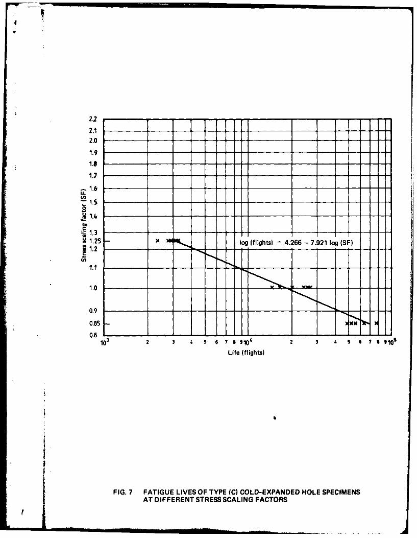
Results of the tests involving cold-expanded holes alone are given in Table 3(C) and Fig. 7.
(D) Interference-fit steel bushed holes. Interference-fit steel bushes were successfully used toprovide significant life extensions for thick-section bolted-joint specimens of the types used inthe two complementary investigations (Refs 5, 6). Although the interference-fit bushing ofsmall diameter bolt holes is not a widely used practice in aircraft structures, lugs incorporatingthin interference-fit bushes are relatively common and significant increases in fatigue performancehave been associated with their use (Refs 22-27). Improvements in fatigue life associated withthe use of interference-fit bushes have been attributed, firstly, to a reduction in the relativemovement between the bush and the lug hole because of the radial pressure associated with theinterference (and hence a reduction in fretting compared with that resulting from a close-fitpin or bolt in the lug); and secondly to the pre-stressing effect of the bush in the hole which,although increasing the mean tensile tangential stress at the boundary of the hole on the trans-verse diameter, can significantly reduce the local alternating stress range in the region of crackinitiation under conditions of repeated external loading (Refs 28-30).
According to GbkgOl (Ref. 29) the optimum design for an interference-fit bush in a lugresults in a bush thickness of 0.05 to 0.10 times the hole diameter; whereas Lambert and Brailey(Ref. 31) have stated that a bush must have a diameter ratio (external/internal) of greater than1.33 to produce the same effective interference as a solid pin of the same external diameter.For the first application in the current investigation the requirement was to provide for theremoval of cracks of at least I mm in depth and to re-use the standard 5 mm bolts. A bush ofnominally 8.15 mm external diameter was selected,* i.e. wall thickness of I .57 mm anddiameter ratio of I 63. Although data on the effects of interference-fit pins and bushes on thefatigue behaviour of aluminium alloy lugs indicate that the extent of the improvement increases
$ This external diameter allowed for the removal of at least 0.5 mm depth of metal after thefirst crack inspection which indicated a "crack-free" condition.
3
with the degree of interference (Refs 22-27), some problems had been experienced in insertingbushes with 0.6 % interference (Ref. 5). Thus, a nominal interference of 0.3 % was adopted forthese tests to ensure that, within the range of accepted manufacturing tolerances for holes andbushes, an effective degree of interference of 0.25% to 0.35 % could be achieved consistently.
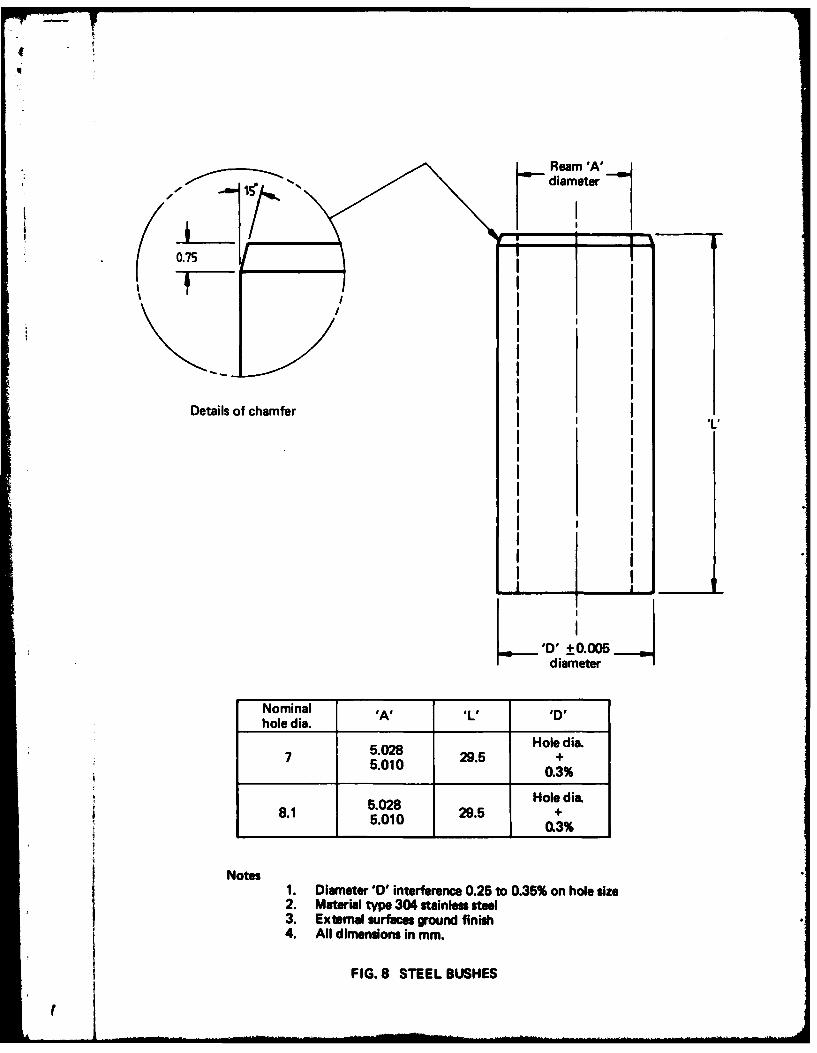
Details of the bushes used in this investigation are given in Fig. 8. The bush material wasgrade 304 austenitic stainless steel having a UTS of 1017 MPa and 0.1 % proof stress of 786 MPa.Stainless steel was selected to provide greater potential for through-the-bush crack detectionusing a rotating probe eddy current system. A barium chromate paste was used as a lubricantand corrosion inhibitor during the insertion of all bushes but, before insertion, the bushes werepassivated in a nitric acid solution and the corresponding holes in the specimens given an Alodine1200 treatment applied by brushing. All bushes were pressed in from the Datum Face using asmall static testing machine, the sequence of bush insertion being holes 1, 5, 2, 4, 3. Individualbush insertion forces are given in Appendix 3. For these 8-15 mm bushed specimens the averagebush insertion force was 17840 N (4010 pounds) with standard deviation of 7400 N (1663 pounds).The test results for specimens of this series are given in Table 3(D).
(E) Cold-expanded and interference-fit bushed holes. Information derived from tests on largerear flange specimens reported in Reference 5 and also on other specimens at a later stage of thesame testing program suggested that cold-expansion alone of the front-flange bolt holes mightnot provide sufficient life to meet the life-of-type requirements of the spar. As the front-flangeholes in the spars in two fatigue test wings and a number of service wings had already been cold-expanded, a series of tests was undertaken to explore whether the fatigue life could be improvedby fitting interferencefit bushes in cold-expanded holes. The combination of cold-expansionand interference-fits has been referred to by Leis and Ford (Ref. 32), and discussed in moredetail by Gibson et al. (Ref. 33). They showed that the resultant hoop residual stress field couldbe derived by combining those associated with each of the separate processes, the nett resultbeing, however, a decrease in the magnitude of compressive stresses close to the hole comparedwith those introduced by the cold-expansion system alone.
The five bolt holes in each of the specimens used in this test series were firstly cold-expandedin an identical manner to those referred to in para. 3(C) above. They were then reamed to 7 mmdiameter and fitted with grade 304 stainless steel bushes at nominally 0-3% interference in asimilar way to those specimens described in para. 3(D). To achieve the recommended minimumexternal/internal diameter ratio of 1 33 and allow standard 5 mm bolts to be re-used for thespecimen assembly the bush thickness adopted was 1 mm. Appendix 3 gives the individual bushinsertion forces. For the 7 mm bushes the average bush insertion force was 12160 N (2734 pounds)with standard deviation of 2320 N (523 pounds). Table 3(E) gives the fatigue results for speci-mens of this type.
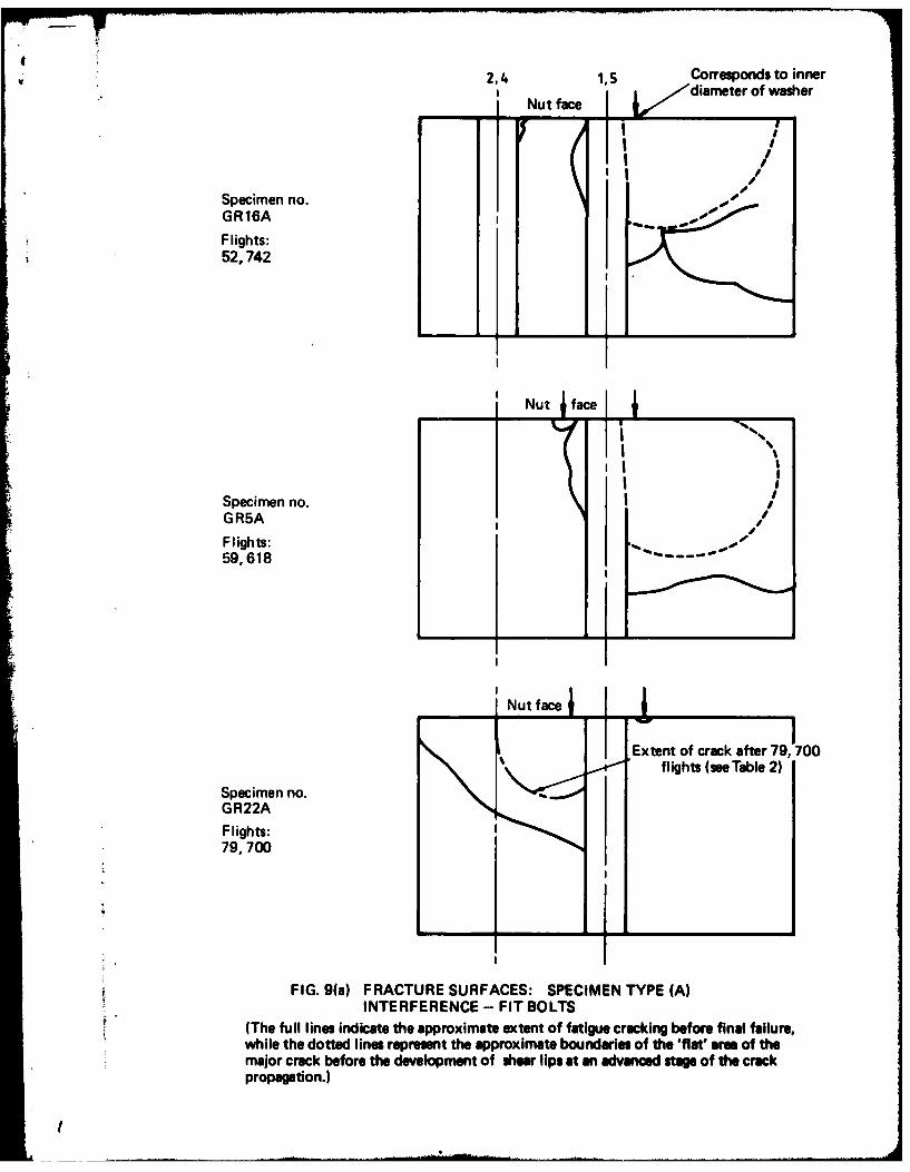
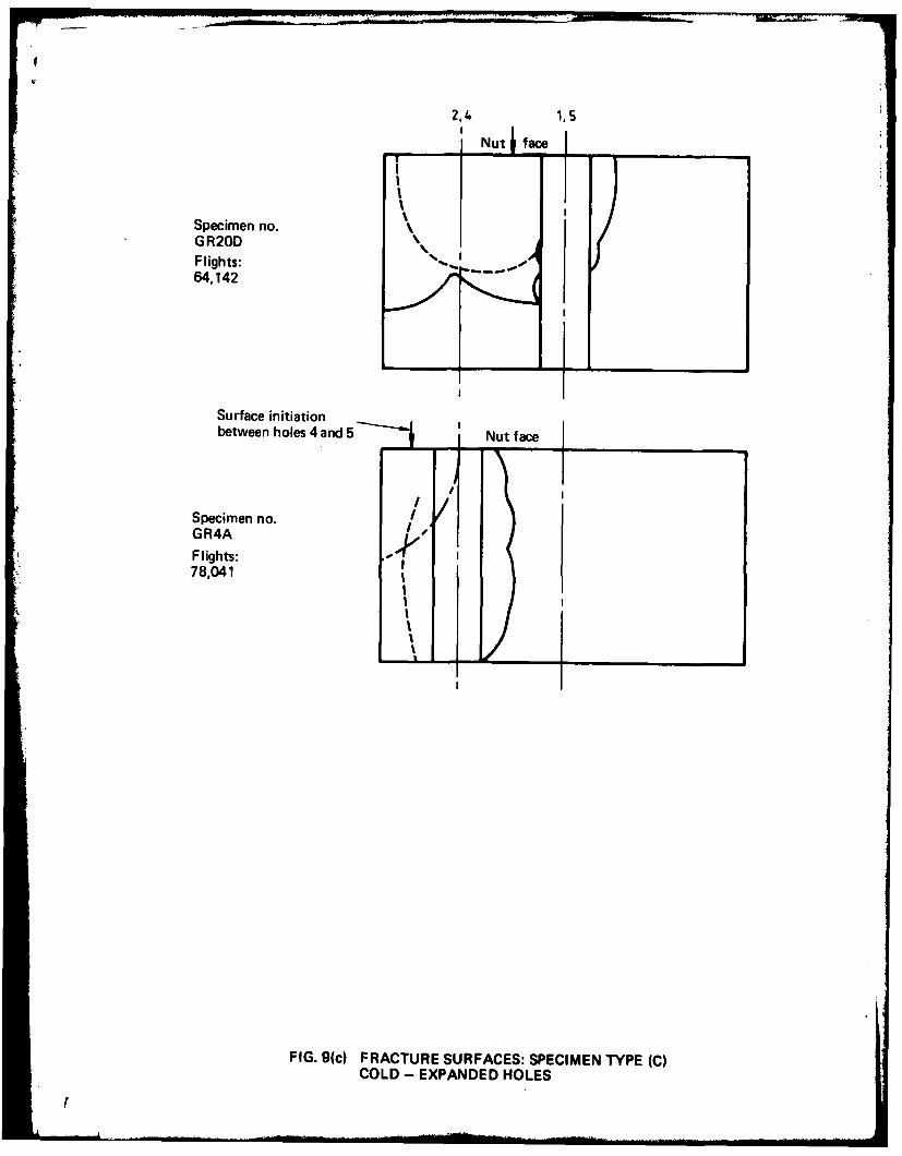
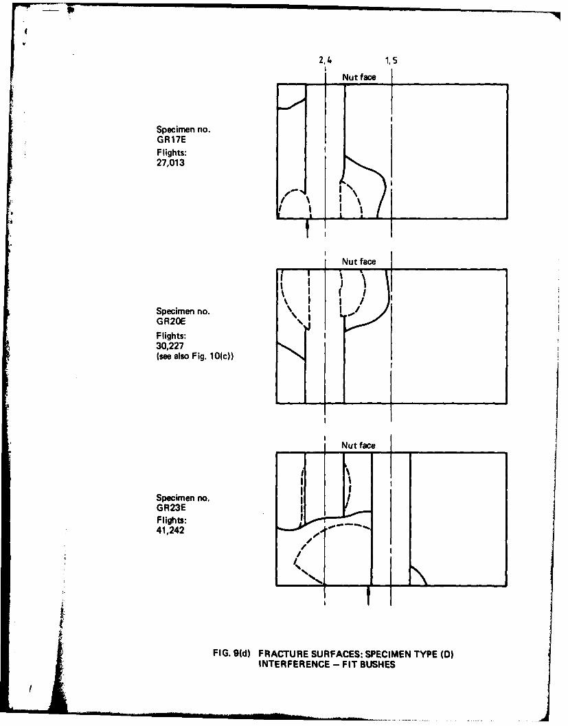
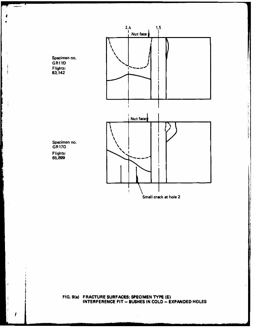
4. FATIGUE FRACTURES
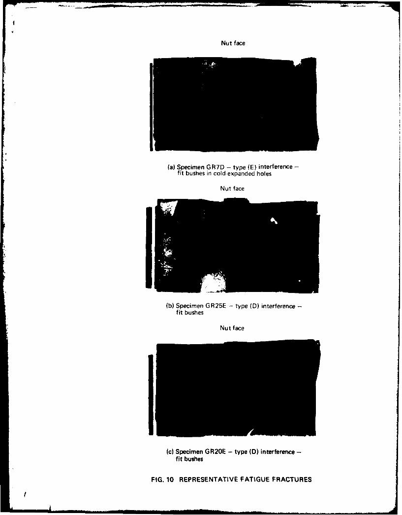
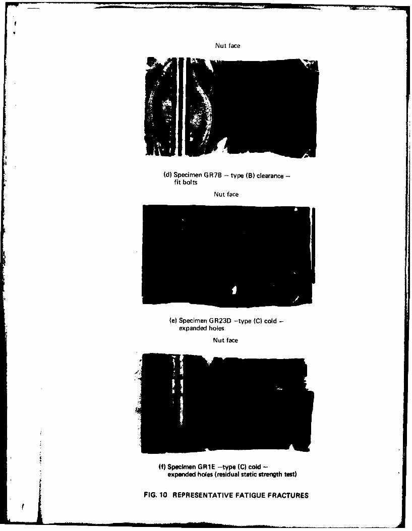
The fracture surfaces of all specimens broken in this investigation are shown diagram-matically in Fig. 9, and photographs of representative fractures are illustrated in Fig. 10. Althoughthe fatigue crack development which led to the final fractures of individual specimens was usuallyassociated with one hole only, the actual fracture path in about 75% of the 39 specimens testedin this investigation passed through an adjacent bolt hole. In at least ten specimens this fracturepath revealed the development of fatigue cracking in an adjacent hole and, in such cases, theillustrations in Fig. 9 represent a composite section embracing the two holes. With the exceptionsof specimens OR3B, GRI5D and GR23E the crack development at the second hole within thefracture path was relatively minor. For GRI5D the extent of fatigue cracking at holes I and 2was such that either hole could be regarded as the "failure hole". Furthermore, for the unbushedspecimens incorporating clearance-fit bolts, i.e. Types (B) and (C), there was usually evidenceof quite extensive fatipe crack development in the equivalent hole at the other end of the testsection to the final fracture hole.
4
I!
Some of the general characteristics of the fatigue fracture development associated with thefive types of specimens can be correlated by combining them into two Groups, i.e.
Group I-those incorporating interference-fit bolts or bushes, i.e. Types (A), (D) and (E).
Group 2-those without interference-fit bolts or bushes, i.e. Types (B) and (C).
This leads to the following observations:
(i) Nine of the 13 specimens in Group I failed at bolt hole I or 5, whereas only one (GR2OD)-or two if GRI5D is included-of the 24 specimens in Group 2 failed at these holes. Mostof the Group 2 specimens failed at holes 2 or 4.
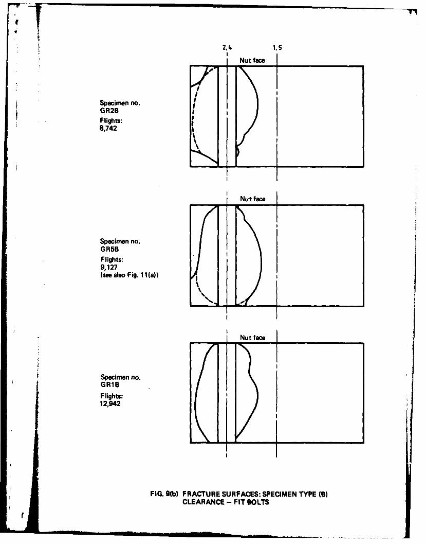
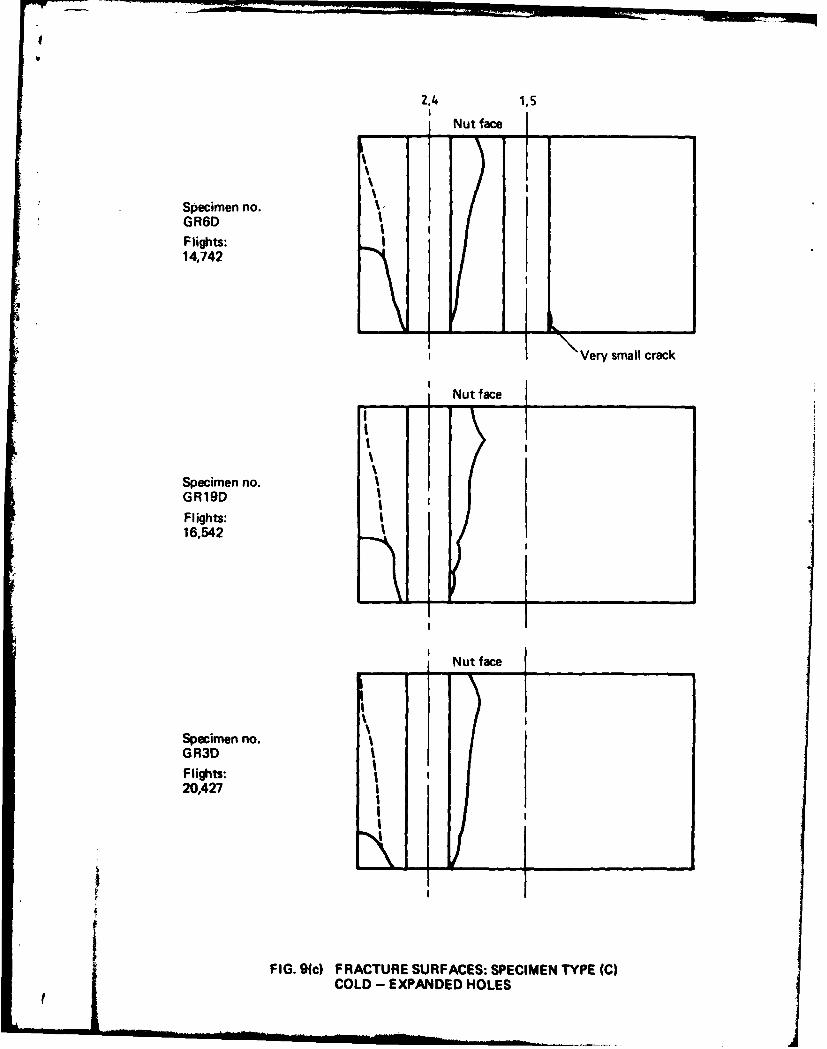
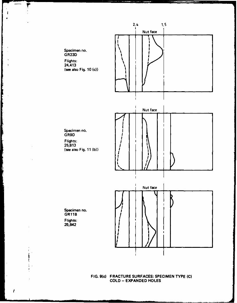
(ii) With one exception (GR2OE-Fig. 10(c)) the primary fatigue crack development in Group Ispecimens was associated with fretting at one or both of the faces of the specimens (Figs10(a) and 10(b)) either from the pressure cone area under the washer at the nut face(Type (A)) or near the bush/hole edge interface (Types (D) and (E)). In the exception(GR20E) the primary fatigue cracking was from multiple-initiation along the bore of abolt hole. Substantial secondary crack initiation down the bore was exhibited by specimenGR22E. This characteristic was also exhibited (but to a much lesser extent) by mostother Group I specimens. Propagation from multiple fatigue crack initiation along thebore of a hole (Figs 10(d) to 10(f)) was, however, the predominant mode of crack develop-ment in specimens of Group 2; the exceptions being GR20D and GRI5D both of whichhave been specifically referred to in (i) above.
(iii) Comparing specimens of Types (B) and (C). Multiple crack initiation along the bores ofholes was common in all of these specimens. In those of Type (B)-clearance bolts inreamed holes-the primary fatigue crack initiation was at about the centre of the section(Fig. 10(d)). For those of Type (C)-clearance bolts in cold-expanded holes-the primaryinitiation was usually at between 2 mm and 4 mm from one of the faces (Fig. 10(e)).
5. FATIGUE CRACK PROPAGATION RATES
Because the variety of primary fatigue crack initiation sites (both at the bores of the holesand at the faces of the specimens) and the marked differences in the shapes of the fatigue crackfronts as they developed, it was decided to limit the.analysis of crack propagation to specimensin which the cracks had initiated at the bore of the holes and had led to the development ofsimilar crack profiles. With these restrictions, only selected specimens of the "5 mm clearance-fitbolts" and "cold-expanded holes" were considered suitable for determining fatigue crackpropagation rates using fractographic examination. Holes fitted with interference-fit bolts andbushes did not satisfy these criteria. The following specimens were selected:
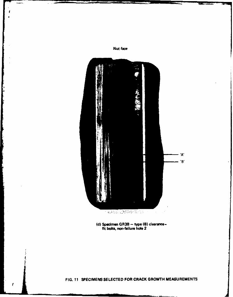
(a) clearance-fit bolts-GR7B, failure hole 4 (Fig. 10(d))-GRSB, failure hole 4 (Fig. I l(a))-GR3B, "non-failure" hole 2* (Fig. I l(d))
(b) cold-expanded -GR9D, failure hole 4 (Fig. I l(b))-GR2D, failure hole 2 (Fig. I 1(c))-GR9D, "non-failure" hole 2.
Using the feature on the fracture surfaces resulting from the application of the -2.5 gto + 7.5 g load as a marker, the incremental crack growth was measured (using an optical micro-scope) backwards from the last application of this load until a crack length at which the markingsbecame unrecognizable. For specimens GR7B, GR5B, GR9D (hole 4) and GR2D this pointwas reached at a distance from the hole (crack origin) of between about 0-3 and 0.6 mm. Forthese specimens crack growth from both sides of the particular failure holes was measured.As the area close to the initiation of the crack at hole 2 in specimen GR3B showed less evidenceof damage during crack development it was possible, in this case, to measure crack increments
* A hole at which a fatigue crack had initiated, but was not in the path of the final fracture.
5

at only 0 02 mm from the hole. The fracture surface adjacent to this particular hole is illustratedin Fig. 1 (d) where the multiple crack origins are clearly shown. Crack growth measurementswere made at both origins 'A' and 'B'. Although the measurements from both origins were ingood agreement, those reported here were from origin 'A' because it was possible to measureto shorter crack lengths in this case. Multiple crack origins for the cold-expanded hole specimenGR9D (hole 2) were also evident. It was hoped to obtain similar measurements at short cracklengths from this hole, but although very clear fractographic markings were evident at cracklengths exceeding about 0-7 mm they suddenly became indistinct and their continuity could notbe identified at shorter crack lengths.
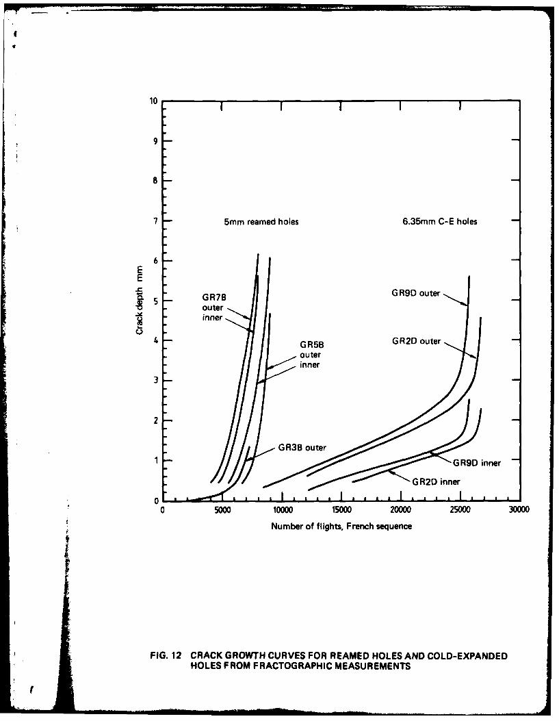
The fatigue crack propagation curves for cracks initiating at the five holes studied in thisinvestigation--three clearance-fit bolt and two-cold expanded holes-are shown in Fig. 12.
6. STATIC FAILING LOADS OF SPECIMENS
The load levels at which individual specimens actually failed by complete fracture weredetermined from the continuous analogue records used to monitor each specimen. They aregiven in Table 3. With only one exception (Specimen GR9D-Type(C)) specimens tested underthe conditions in which +7.5 g corresponded to 235 MPa all failed at loads just less than that forthe +6.5 g level or between the +6.5 g level (274 kN) and +7-5 g level (316 kN). In general,when failure occurred in flight 42 (i.e. the Type A' flight which included the only applicationof the +7.5 g level in the 100 flight sequence), the failing load exceeded 274 kN; and whenit was less than 274 kN the flight at failure corresponded to one of the 18 occurrences of theType A flight per 100 flights, in which the maximum level is +6.5 g.
The multiplicity of fatigue crack origins, complicated crack geometries and depths of cracksrelative to the distance from the bolt holes to the sides of the specimens were not conducive tomaking meaningful estimates of failing loads using methods of analytical fracture mechanics,as typified by those of Newman and Raju (Ref. 35).
7. DISCUSSION
Table 4 summarises the results of the fatigue tests and provides a comparison of the averagelives for the five hole treatments covered in this investigation. The results of Swiss (Ref. 7) andFrench (Ref. 8) fatigue investigations on specimens of essentially the same aluminium alloyincorporating interference-fit bolts, clearance-fit bolts and cold-expanded holes and tested undersimilar flight-by-flight loading sequences are summarised in Table 5.
These Tables show the superiority of the interference-fit bolt fastening system relative tothe other four types of systems investigated as refurbishment options for the particular part of theMirage 1110 spar under consideration. They indicate, in particular, the significant reductionsin fatigue lives resulting from the use of clearance rather than interference-fit bolts (a life ratioof 0 II in the current investigation and 0-12 in the Swiss tests), and the poor performance ofcold-expanded hole specimens compared with those having interference-fit bolts; life ratios of0.30, 0-42 and 0.52 in the current, French and Swiss tests respectively. The last results confirmthe findings of Moore (Ref. 36) that interference is about twice as effective as hole cold-expansionin fatigue life enhancement. Nevertheless, cold-expanding alone, the installation of interference-fit bushes and a combination of the two provide increased lives compared to the use of clearance-fit bolts.
Because of the nominally higher interference-fit stresses induced by the bolts compared withthe bushes (see Table 2) it was not unexpected that specimens incorporating interference fit-boltsdemonstrated significantly longer lives than those with interference-fit bushes alone. However,as indicated in Appendix I, the cold-expanding and bushing systems all involved increases inthe nett are4 stresses compared with those employing 5 mm bolts in 5 mm holes. Reference toFigure 7 indicates that under the particular loading spectrum and sequence used, each 10%increase in stress reduces the total life to about half that at the lower stress level. If, in the caseof the cold-expanded and bushed specimens, the comparison with the interference-fit bolt speci-mens is made on the basis of nett area stresses, the equivalent fatigue life (derived using theequation for the curve in Fig. 7) is 82,035 flights. This is not significantly different from the 72,524
6

E
flights of the interference-fit bolt specimens. Thus, providing the nett areas were the same, thecombination of cold-expanding and bushing-which would provide the option for an easilydemountable fastener-could provide a similar fatigue performance to that resulting from theinitial selection of interference-fit bolts. Furthermore, in the present refurbishment situation,the bushing of a cold-expanded bolt hole has the potential for providing a significant increase inlife compared with that obtainable by cold-expansion alone, in the event that the life achievedby cold-expansion alone is not adequate.
When assessing the relative fatigue performances of the various systems employed in thecurrent investigation it should be noted that for specimens incorporating clearance-fit fasteners thefatigue failures usually developed from multiple crack initiation within the bore of the holes,whereas those incorporating interference-fit bolts or bushes failed from fretting-initiated crackson one or both of the faces of the specimens a little distance from the hole edge. Presumably,if surface-fretting crack initiation had been suppressed, any "hole-bore" cracks which hadinitiated in the interference-fit specimens would have resulted in greater lives than actuallyoccurred, and thus the lives for most of the specimens in Tables 3(A), 3(D) and 3(E) representthe lower limits of those which might be associated with these particular fastener systems underthe current test conditions.
Figure 12 illustrates the beneficial effects on total life by cold-expanding compared withthe simple reaming of bolt holes over the range of crack length measurements. It also shows(except in the final stage of crack development when the crack lengths are relatively long) thatthe propagation rates of fatigue cracks emanating from cold-expanded holes are considerablyless than for cracks from non cold-expanded holes. Although the fatigue crack developmentshown in Fig. 12 represents a situation of crack initiation within the bores of 28 mm long holeswell away from the faces of the specimens, the shapes of the fractographically-determined crackpropagation curves for both "as-reamed" and "cold-expanded'" hole specimens are quite similarto those reported by Chandawanich and Sharpe (Ref. 37) for surface crack measurements fromopen holes in 7075-T6 aluminium alloy sheet. Clearly, cold-expansion of the holes has notprevented crack initiation at the holes in either the current tests or those reported in Reference 37.However, because of the differences in specimen design, i.e. filled and open holes, the complica-tions of bolt bearing at the hole surface and fretting would have been absent in the tests ofChandawanich and Sharpe. It is thus of interest that the crack propagation behaviour found inthe current tests and those of Chandawanich and Sharpe appear to be similar, irrespective ofthe likely differences in fatigue crack initiation in the two types of specimens used.
In contrast to the present investigation, Chandawanich and Sharpe were able to measurecrack growth for cracks as small as 0. A mm in length, and their data for cold-expanded holespecimens suggests a relatively rapid rate of crack propagation from initiation to a length ofabout 0.5 mm. Similar behaviour has been reported by Noronha et al. (Ref. 38) who haveinferred that for short cracks (less than 0.7 mm length in their specimens) the fatigue crackpropagation rate from cold-expanded holes is greater than from conventionally drilled holes.In reviewing the crack growth behaviour of short cracks initiating at notched specimens, ElHaddad et al. (Refs 40, 41) have shown that such cracks can have considerably higher crackpropagation rates than would be predicted by stress-intensity crack growth laws for large cracks.Under remote tension loading the initial rapid propagation rates decrease as the crack growsthrough the diminishing stress or strain concentration field of the notch. After reaching a minimumvalue the crack propagation rate increases as it grows past the zone of influence of the notch,and its growth characteristics then become describable by the fracture mechanics solutions forlong cracks. Although this argument could be extended to the case of short cracks from cold-expanded holes, the situation is complicated by the interaction of the locally high tensile stressfield resulting from the stress concentrating effect of the hole and that associated with hole cold-expansion-both before and after fatigue crack initiation. Furthermore it is likely that, underfatigue cycling, some gradual relaxation of the residual stresses would occur (Ref. 42).
Examples of the residual stress distributions surrounding cold-expanded holes in aluminiumalloy sheet/plate given by Chang (Ref. 13), Gibson et al. (Ref. 33) and Chandawanich andSharpe (Ref. 37) suggest that in an uncracked specimen, the transition from a compressive to atensile residual stress field occurs between about two-thirds and one hole radius from the edgeof the hole. Although the residual stress distribution will change as the fatigue crack propagates.it is of interest that in both the current tests and those reported in Reference 37 the transition
7

* from an almost constant crack propagation rate (the intermediate stage occupying some 70%of the crack propagation life) to the much more rapid crack growth prior to final failure occurs ata crack length corresponding to about this same distance from the edge of the hole. Chanda-wanich and Sharpe have also demonstrated the significance of crack closure effects within thecompressive stress zone during the intermediate stage of crack propagation from cold-expandedholes. Nevertheless, the fact that fatigue cracks propagated through the zone of compressiveresidual stress (although at a reduced rate compared with those from non cold-expanded holes)indicates that the effective stress intensity at the crack tip exceeded the threshold stress intensityrange for crack propagation. Otherwise, the crack would have been contained within the com-pressive stress zone and met the criterion enunciated by Grandt and Gallagher (Ref. 43) for thedesign of "long-life" fastener systems.
A concern which has been expressed on several occasions (Refs 44-46) is that, althoughfatigue life enhancement systems can provide an acceptable increase in average lives, they mayresult in increased scatter in life. Thus, at the usually acceptable probabilities of failure, littlemight be gained from the fatigue viewpoint in adopting some systems. It is therefore of interestto note that in the current tests the scatter in life (defined as the standard deviation of log. life)for the 5 mm clearance-fit bolt condition (which resulted in the worst fatigue performance)and that for each of the four life-enhancement systems investigated is not significantly different.
It cannot be oveemphasised that the effectiveness of interference-fit bolt and bush faste,systems for providing consistent increases in fatigue lives relies critically on the achievenof the correct degree of bolt or bush to hole interference along the entire length of the holearound the whole periphery. This, in turn, requires the maintenance of close dimensi '
tolerances during the manufacture of the bolt/bush and machining of the hole, and very cacontrol during the insertion of the bolts or bushes. If these can be achieved, the use of interfere -fit bolts or bushes can provide a much more effective fastener system than that embodying hcold-expansion alone. Nevertheless, an important consideration in the selection of a life-enhance-ment fastener system could be the philosophy of in-service monitoring of the joint in question.If non-destructive inspections of the holes were required to provide added assurance of theabsence of crack development, or a requirement existed for disassembly of the joint, these actionscould be more readily achieved in situations where the fasteners were easily removable. Underthese circumstances a simple hole cold-expansion system could, despite its relatively worsefatigue performance, be an acceptable alternative to the use of interference-fit bolts or bushes.It also has the advantage of allowing the use of wider dimensional tolerances than in the inter-ference-fit cases.
& CONCLUSIONS
1. This investigation has demonstrated the effectiveness of interference-fit bolts or bushes andhole cold-expansion for improving the fatigue lives of thick-section aluminium alloy boltedjoints. Compared with joints fitted with close-fit bolts in reamed holes, the ratio of the livesof specimens incorporating interference-fit bolts, interference-fit steel bushes and cold-expansion of bolt holes were approximately 9:1, 5:1 and 3:1 respectively.
* 2. Hole cold-expansion followed by the installation of interference-fit bushes resulted in a furtherincrease in fatigue life compared with that resulting from interference-fit bushes alone.
3. Fatigue crack propagation from the bores of cold-expanded holes is much slower than thatfrom non cold-expanded (reamed) holes until the crack length is close to the region of
* transition from the residual compressive to tensile stress zone around the cold-expanded hole.
4. Under the particular loading spectrum and sequence used in this investigation, each 10%increase in stress reduces the total life to about half that at the lower stress level.
5. If the refurbishment of the front flange of the Mirage Ill main spar requires that the boltholes be enlarged to remove fatigue cracks and the holes to be periodically inspected in service,theM the incorporation of interference-fit bushes either alone or in combination with cold-expansion of the holes should enable a satisfactory extension in fatigue life to be achieved inservice for this detail of interest in the structure.
iS,

r
6. The effectiveness of interference-fit bolt and bush fastener systems for providing consistentincreases in fatigue lives relies critically on the achievement of the correct interferences which,in turn, require the maintenance of close dimensional tolerances for bolts, bushes and holes,and careful control during the insertion of bolts or bushes.
ACKNOWLEDGEMENTS
The authors wish to express their thanks to the staff of Structures Division who determinedthe mechanical properties of the test material, to Mr L. Wilson of Materials Division for carryingout the chemical analysis, and to Corporals A. Green and S. Nicoll of the RAAF for assistancein the preparation of test specimens and photography of the fracture surfaces.
modf •
( =i H I I i . ... .. .. .. . . .
REFERENCES
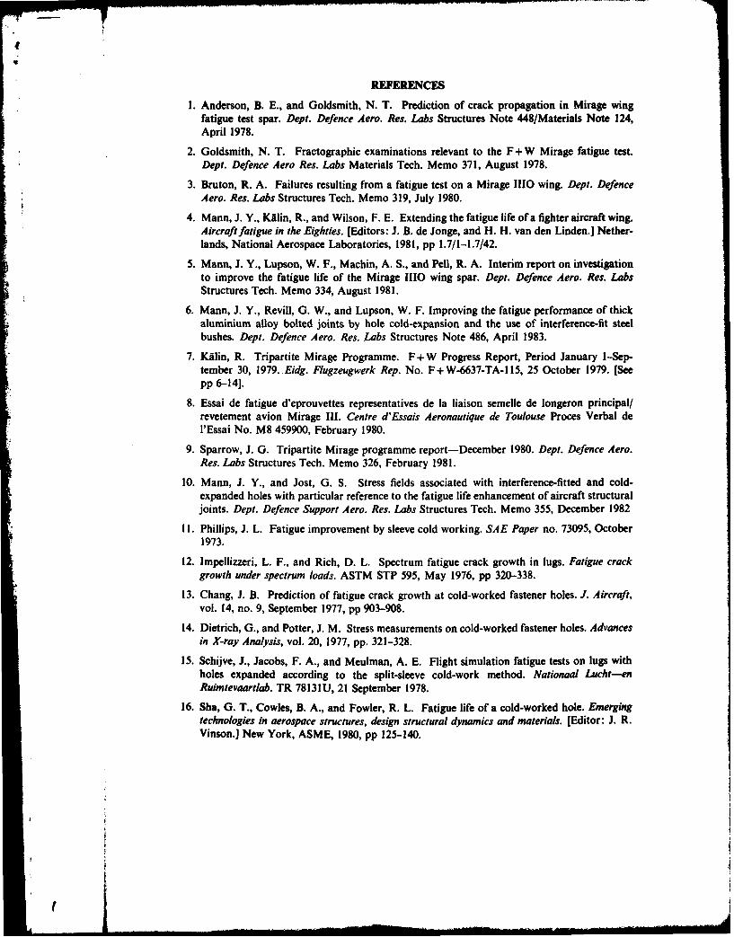
1. Anderson, B. E., and Goldsmith, N. T. Prediction of crack propagation in Mirage wingfatigue test spar. Dept. Defence Aero. Res. Labs Structures Note 448/Materials Note 124,April 1978.
2. Goldsmith, N. T. Fractographic examinations relevant to the F+W Mirage fatigue test.Dept. Defence Aero Res. Labs Materials Tech. Memo 371, August 1978.
3. Bruton, R. A. Failures resulting from a fatigue test on a Mirage 1110 wing. Dept. DefenceAero. Res. Labs Structures Tech. Memo 319, July 1980.
4. Mann, J. Y., KAlin, R., and Wilson, F. E. Extending the fatigue life of a fighter aircraft wing.Aircraft fatigue in the Eighties. [Editors: J. B. de Jonge, and H. H. van den Linden.] Nether-lands, National Aerospace Laboratories, 1981, pp 1.7/1-1.7/42.
5. Mann, J. Y., Lupson, W. F., Machin, A. S., and Pell, R. A. Interim report on investigationto improve the fatigue life of the Mirage 1110 wing spar. Dept. Defence Aero. Res. LabsStructures Tech. Memo 334, August 1981.
6. Mann, J. Y., Revill, G. W., and Lupson, W. F. Improving the fatigue performance of thickaluminium alloy bolted joints by hole cold-expansion and the use of interference-fit steelbushes. Dept. Defence Aero. Res. Labs Structures Note 486, April 1983.
7. KAlin, R. Tripartite Mirage Programme. F+W Progress Report, Period January 1-Sep-tember 30, 1979. Eidg. Flugzeugwerk Rep. No. F+ W-6637-TA- 115, 25 October 1979. [Seepp 6-14].
8. Essai de fatigue d'eprouvettes representatives de la liaison semelle de longeron principal/revetement avion Mirage II1. Centre d'Essais Aeronautique de Toulouse Proces Verbal del'Essai No. M8 459900, February 1980.
9. Sparrow, J. G. Tripartite Mirage programme report-December 1980. Dept. Defence Aero.Res. Labs Structures Tech. Memo 326, February 1981.
10. Mann, J. Y., and Jost, G. S. Stress fields associated with interference-fitted and cold-expanded holes with particular reference to the fatigue life enhancement of aircraft structuraljoints. Dept. Defence Support Aero, Res. Labs Structures Tech. Memo 355, December 1982
11. Phillips, J. L. Fatigue improvement by sleeve cold working. SAE Paper no. 73095, October1973.
12. Impellizzeri, L. F., and Rich, D. L. Spectrum fatigue crack growth in lugs. Fatigue crackgrowth under spectrum loads. ASTM STP 595, May 1976, pp 320-338.
13. Chang, J. B. Prediction of fatigue crack growth at cold-worked fastener holes. J. Aircraft,vol. 14, no. 9, September 1977, pp 903-908.
14. Dietrich, G., and Potter, J. M. Stress measurements on cold-worked fastener holes. Advancesin X-ray Analysis, vol. 20, 1977, pp. 321-328.
15. Schijve, J., Jacobs, F. A., and Meulman, A. E. Flight simulation fatigue tests on lugs withholes expanded according to the split-sleeve cold-work method. Nationaal Lucht-enRuimtevaartlab. TR 78131U, 21 September 1978.
16. Sha, G. T., Cowles, B. A., and Fowler, R. L. Fatigue life of a cold-worked hole. Emergingtechnologies in aerospace structures, design structural dynamics and materials. [Editor: J. R.Vinson.] New York, ASME, 1980, pp 125-140.
'I
I
w
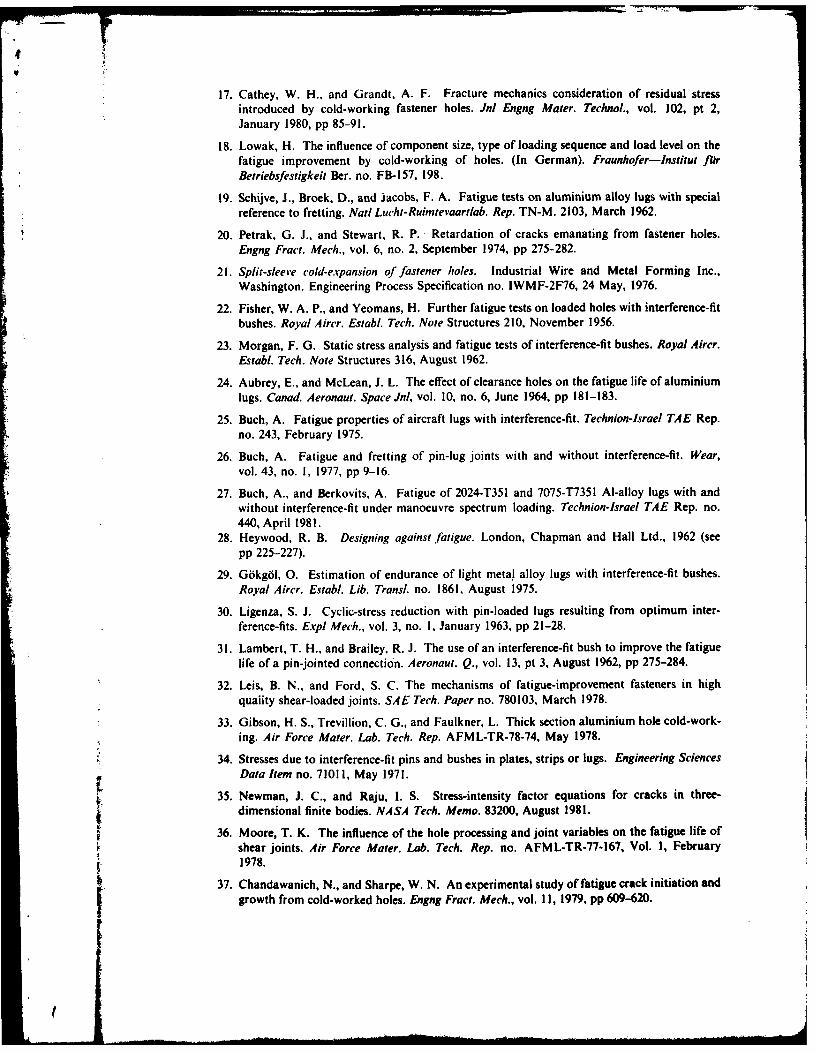
17. Cathey, W. H., and Grandt, A. F. Fracture mechanics consideration of residual stressintroduced by cold-working fastener holes. Jnl Engng Mater. Technol., vol. 102, pt 2,January 1980, pp 85-91.
18. Lowak, H. The influence of component size, type of loading sequence and load level on thefatigue improvement by cold-working of holes. (In German). Fraunhofer-Institut farBetriebsfestigkeit Ber. no. FB-157, 198.
19. Schijve, J., Broek, D., and jacobs, F. A. Fatigue tests on aluminium alloy lugs with specialreference to fretting. Nail Lucht-Ruimtevaartlab. Rep. TN-M. 2103, March 1962.
20. Petrak, G. J., and Stewart, R. P. Retardation of cracks emanating from fastener holes.Engng Fract. Mech., vol. 6, no. 2, September 1974, pp 275-282.
21. Split-sleeve cold-expansion of fastener holes. Industrial Wire and Metal Forming Inc.,Washington. Engineering Process Specification no. IWMF-2F76, 24 May, 1976.
22. Fisher, W. A. P., and Yeomans, H. Further fatigue tests on loaded holes with interference-fitbushes. Royal Aircr. Establ. Tech. Note Structures 210, November 1956.
23. Morgan, F. G. Static stress analysis and fatigue tests of interference-fit bushes. Royal Aircr.Establ. Tech. Note Structures 316, August 1962.
24. Aubrey, E., and McLean, J. L. The effect of clearance holes on the fatigue life of aluminiumlugs. Canad. Aeronaut. Space Jnl, vol. 10, no. 6, June 1964, pp 181-183.
25. Buch, A. Fatigue properties of aircraft lugs with interference-fit. Technion-Jsrael TAE Rep.no. 243, February 1975.
26. Buch, A. Fatigue and fretting of pin-lug joints with and without interference-fit. Wear,vol. 43, no. 1, 1977, pp 9-16.
27. Buch, A., and Berkovits, A. Fatigue of 2024-T351 and 7075-T7351 Al-alloy lugs with andwithout interference-fit under manoeuvre spectrum loading. Technion-Israel TAE Rep. no.440, April 1981.
28. Heywood, R. B. Designing against fatigue. London, Chapman and Hall Ltd., 1962 (seepp 225-227).
29. Gokgol, 0. Estimation of endurance of light metal alloy lugs with interference-fit bushes.Royal Aircr. Establ. Lib. Transl. no. 1861, August 1975.
30. Ligenza, S. J. Cyclic-stress reduction with pin-loaded lugs resulting from optimum inter-ference-fits. Expl Mech., vol. 3, no. 1, January 1963, pp 21-28.
31. Lambert, T. H., and Brailey, R. J. The use of an interference-fit bush to improve the fatiguelife of a pin-jointed connection. Aeronaut. Q., vol. 13, pt 3, August 1962, pp 275-284.
32. Leis, B. N., and Ford, S. C. The mechanisms of fatigue-improvement fasteners in high
quaity shear-loaded joints. SAE Tech. Paper no. 780103, March 1978.
33. Gibson, H. S., Trevillion, C. G., and Faulkner, L. Thick section aluminium hole cold-work-
ing. Air Force Mater. Lab. Tech. Rep. AFML-TR-78-74, May 1978.
34. Stresses due to interference-fit pins and bushes in plates, strips or lugs. Engineering SciencesData Item no. 71011, May 197 1.
35. Newman, J. C., and Raju, 1. S. Stress-intensity factor equations for cracks in three-
dimensional finite bodies. NASA Tech. Memo. 83200, August 1981.
36. Moore, T. K. The influence of the hole processing and joint variables on the fatigue life ofshear joints. Air Force Mater. Lab. Tech. Rep. no. AFML-TR-77-167, Vol. 1, February1978.
37. Chandawanich, N., and Sharpe, W. N. An experimental study of fatigue crack initiation and
growth from cold-worked holes. Engng Fract. Mech., vol. II, 1979, pp 609-620.
: + -: - -=. . I -' .. I

4
38. Noronha, P. J., Henslee, S. P., Gordon, D. E., Wolansi, Z. R., and Yee, B. G. W. Fasteerhole quality. Tech. Rep. AFFDL-TR-78-206, vol. 1, December 1978.
39. Ford, D. G. Maximum likelihood estimators for truncated samples from normal populations.Dept. Supply, Aero. Res. Labs Rep. SM.264, October 1958.
40. El Haddad, M. H., Smith, K. N., and Topper, T. H. Fatigue crack propagation of shortcracks. Trans. ASME (J. Engng Mater. Technol.), vol. 101, no. 1, January 1979, pp 42-46.
41. El Haddad, M. H., Dowling, N. E., Topper, T. H., and Smith, K. N. J integral applicationsfor short fatigue cracks at notches. Int. Jnl Fracture, vol. 16, no. 1, February 1980, pp 15-30.
42. Schitz, W. Improvement of fatigue strength by residual compressive stresses. Atti del 20convegno sulla fatica nelle strutture aerospaziali, Vol. 1. Pisa, Vigno Cursi Editore, 27-29February 1980, pp 2.1-2.13.
43. Grandt, A. F., and Gallagher, J. P. Proposed fracture mechanics criteria to select mechanicalfasteners for long service lives. Fracture toughness and slow-stable cracking. ASTM STP 559,1974, pp 283-297.
44. Berens, A. P., Hovey, P. W., and Kozel, P. Performance of fatigue life enhancing fastenersin titanium alloys. Rep. Naval Air Devel. Cent. no. NADC-81061-80, September 1980.
45. Schuitz, W. Fatigue life improvement of high-strength materials by shot peening. FirstInternational Conference on shot peening. Oxford, Pergamon Press, 1982, pp 423-433.
46. Schitz, D. Planning and analyzing a fatigue test programme. Fatigue test methodology.AGARD lecture series no. 118, October 1981, pp 2.1-2.22.
e2

APPENDIX I
3 Specimen type Hole diameter, gross area* nominal (mm) nett area
Interference-fit bolts 496 1.12
Clearance-fit bolts 5.02 1.12
Cold-expanded holes 6.36 1.15
Interference-fit bushes 8.15 !20
Cold-expanded holesand interference-fitbushes 7.02 1.17
(Gross area = 1344 mm').
APPENDiX 2
Derhads d sm hiThe stress at 7.5 g was derived from strains measured at gpuge 1.4T during the 1979 strain
survey of the left-hand Swiss Mirage test wing. This puge was located at the inner surface ofthe lower front flange of the main spar between bolt hole no. 14 and the spar web, and a multi-plying factor of I 2 was used to estimate the strain at the Swiss failure location (hole no. 12).Two different methods were used to estimate the stan at 7-5 g, and the value of 235 MPa(34,100 psi) adopted for this investigation was an average of the two. The firt was determineddirectly from the actual numerical value of strain at 5 g usn the ratio 7 . (S)/S (g) andresulted in a strain of 3240 microstrain (stres 237 MP&; 34,340 psi). The second method wasbased on the average microstrain per g from the I g to 5 g increment (Ref. 9) and resulted in astrain of 3201 microstrain (stress 234 MPa; 33,930psi).
APPENDIX 3
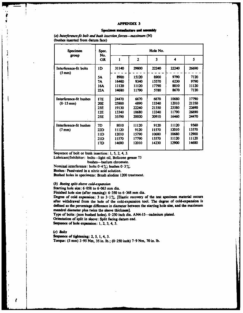
Spedom .n ea.m n mWd aMUM"j t(a) hiterference-fit bolt and bush insertion forces--maxmw (N)
(bushes inserted from datum face)
Specimen Spec. Hole No.
group No.OR 1 2 3 4 5
Interference-fit bolts ID 31140 29800 22240 22240 26690(5 mam )- - - - - - - - - - - - - - - - - - - - - - - - -
5A 8900 15120 8900 9790 71207A 16460 9340 15570 6230 979016A 11120 11120 17790 8010 11 1222A 14680 i11790 5780 8670 7120
Interference-fit bushes 17E 24470 6670 6670 10680 17790(8.15 mm) 20E 25800 4890 13340 12010 21350
23E 19130 22240 21350 23580 2269012E 13340 10680 13340 11790 2669025E 35590 20020 20910 16460 24470
Interference-fit bushes 7D 8010 11120 9120 11120 9560(7 mm) 22D 11120 9120 11570 12010 13570
11D 12010 15790 10680 10680 1290021D 11570 17790 15570 11120 1112017D 14680 12010 14230 12900 14680
Sequence of bolt or bush insertion: 1, 5, 2, 4, 3.Lubricant/Inhibitor: bolts-light oil, Bolicone grease 73
bushes-barium chromate.Nominal interference: bolts 0-4%; bushes 0.3%.Bushes: Passivated in a nitric acid solution.Bushed holes in specimens: Brush alodine 1200 treatment.
(b) Boeing split-sleeve cold-expansionStarting hole size: 6.058 to 6.063 mm dia.Finished hole size (after reaming): 6.350 to 6 368 mm dia.Degree of cold expansion: 3 to 3.1 %. [Elastic recovery of the test specimen material occursafter withdrawal from the hole of the cold-expansion tool. The degree of cold-expansion isdefined as the percentage difference in diameter between the starting hole size, and the maximummandrel diameter plus twice the sleeve thickness).Type of bolts: (non bushed holes). 0.250 inch dia. AN4-15-cadmium plated.Orientation of split in sleeve: Split facing datum end.Sequence of hole expansion: 1, 2, 3, 4, 5.
() ltsSequence of tightening: 2, 5, 1, 4, 3.Torque: (5 mm) 3.95 Nm, 35 in. lb.; (0.250 inch) 7.9 Nm, 70 in. lb.
S f

w- ~TABLE 1
____________ (a) Chemical comvposition () _______
Element tOpecification British Standard Test materialA7-U4SG (2214) 1,168: 1978 GR
Cu 3-9-S- 3-9-50 4,29Mg 0-2-08 0-2-0-8 0-43
Ma 0-4-1-2 0-4-1-2 0-76
Si 0-5-1-2 0 -5-0.9 0-74Ti 0 l15max. 0- 15max. not analyzedCr 0- 10max. 0- 10max. 0.01Zn 0 -25 max. 0-25max. <0-20
_________________(b) Static tensile
Property tSpecification British Standard Test materialA7-U4SG (2214) L169: 1978 GR
0 -I% proof stress - -466(MNI) (sd 10)0-2% proof stress 390 440 474(MNa) (sd 12)Ultimate tensile stress 450 490 524(MPa) (sd 12)Elongation (%) 5 7 11
(sd 2)0 A1% PS/Ult -- 0.89
sd =standard deviation.
(c) Fractur" toughness (Kic)
Specimen thickness (mm) Mpa.mA/2 ksi.in11 2
25 34.5* 31-*19 32 -Ot 29-2t
Average of two specimens from the one bar.t Average of five specimens from different bars.t Condtons dle controle des prodkdes lamines en aliages d'auminlwn utiises danslet constructions arspatiales. Ministere de la Defense, Direction Technique desConstruction Aeronautiques AIR 9048, Edition No. 1, 26 December, 1978, p. 91.[Specification A7-U4SG superseded A-U4SG, the material from which the sparswere manufactured].

TABLE 2
Red"inm tuil. hoop smsat hole kbci by laterme-0l boltsad buihe (Ref. 34)____
MaximumCondition Interference hoop stress
M% (MPa)
5 mm interference-fit steel bolt 0-4 193
8 -153mm external diameter steel bush 0-25 117(5 mm internal) 0-35 163
7 mm external diameter steel bush 0-25 95(5 mm internal) 0-35 133

eS
TABLE 3
_ _ _Fatpe test resuts
Specimen No. Gross area stress Life Failure Failing loadGR (MPa) at +75 g* (flights) hole No. (kN)
(A) 5 mm Interference-fit bolts (04 %-0.8%)16A 235 52,742 1 j 2765A 235 59,618 5 26822A 235 79,700 Test terminated. Specimen not disassembled.
[81,5001t Further testing indicated that crack ofS1I mm x 9 mm at hole I had developed by79,700 flights (see Fig. 9A)
7A 235 92,700 Test terminated. Specimen disassembled. Nocrack indications
:Log. average = 72,524; s.d. = 0. I13
ID 210 80,200 Test terminated. Specimen disassembled. Nocrack indications
(B) 5 mm Clearance-fit bolts6B 235 5,642 4 2883B 235 7,399 4 2667B 235 8,099 4 2642B 235 8,742 2 2935B 235 9,127 4 267
Log. average = 7,695; s.d. = 0083
IB 210 12,942 2 281
(C) Cold-expanded/holes-Boeingprocess 2 5-3.4 % expansion (0' 25 inch AN4 bolts-6 .35 mam)16D 294 2,362 2 33626D 294 2,818 4 3405D 294 2,913 4 3388B 294 3,136 4 33012B 294 3,223 4 332
Log. average = 2,874; s.d. = 0.053
6D 235 14,742 4 30319D 235 16,542 4 2643D 235 20,427 4 26523D 235 24,413 4 2719D 235 25,813 4 240IIB 235 25,842 2 2832D 235 26,781 2 267
Log. average 21,570; s.d. 0.104
,V
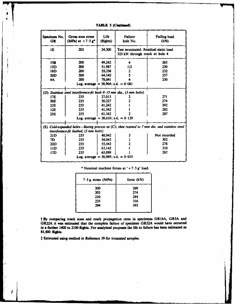
TABLE 3 (Ceaaed)
Specimen No. Gross area stress Life Failure Failing loadGR (MPa) at + 7.5 * (flights) hole No. (kN)
IE 203 24,300 Test terminated. Residualstatic load523 kN through crack at hole 4
10B 200 49,242 4 26515D 200 51,987 1/2 230,1D 200 55,336 2 23220D 200 64,142 5 2574A 200 78,041 4 230
Log. average = 58,904; s.d. = 0.081
(D) Stainless steel interference-fit bush 81 J5 mm dia., (5 mm bolts)17E 235 27,013 2 27120E 235 30,227 2 27423E 235 41,242 1 29212E 235 41,542 1 28225E 235 61,342 2 287
Log. average - 38,610; s.d. = 0.139
(E) Cold-expanded holes-Boeing process as (C); then reamed to 7 mm dia. and stainless steelinterference-fit bushed, (5 mm bolts)21D 235 48,042 5 Not recorded7D 235 54,042 1 30222D 235 55,542 2 27811D 235 63,142 ! 31017D 235 65,899 1 267
Log. average = 56,969; s.d. = 0.055
* Nominal machine forces at '+ 7.5 g' load.
7.5 g stress (MPa) force (kN)
200 269203 274210 284235 316294 395
t By comparing crack ses and crack propagation rates in specimens GRI6A, GRSA andGR22A it was estimated that the complete failure of specimen GR22A would have occurredin a futher 1400 to 2100 flights. For analytical purposes the life to failure has been estimated as81,500 fights.
t Estimated using method in Reference 39 for truncated samples.
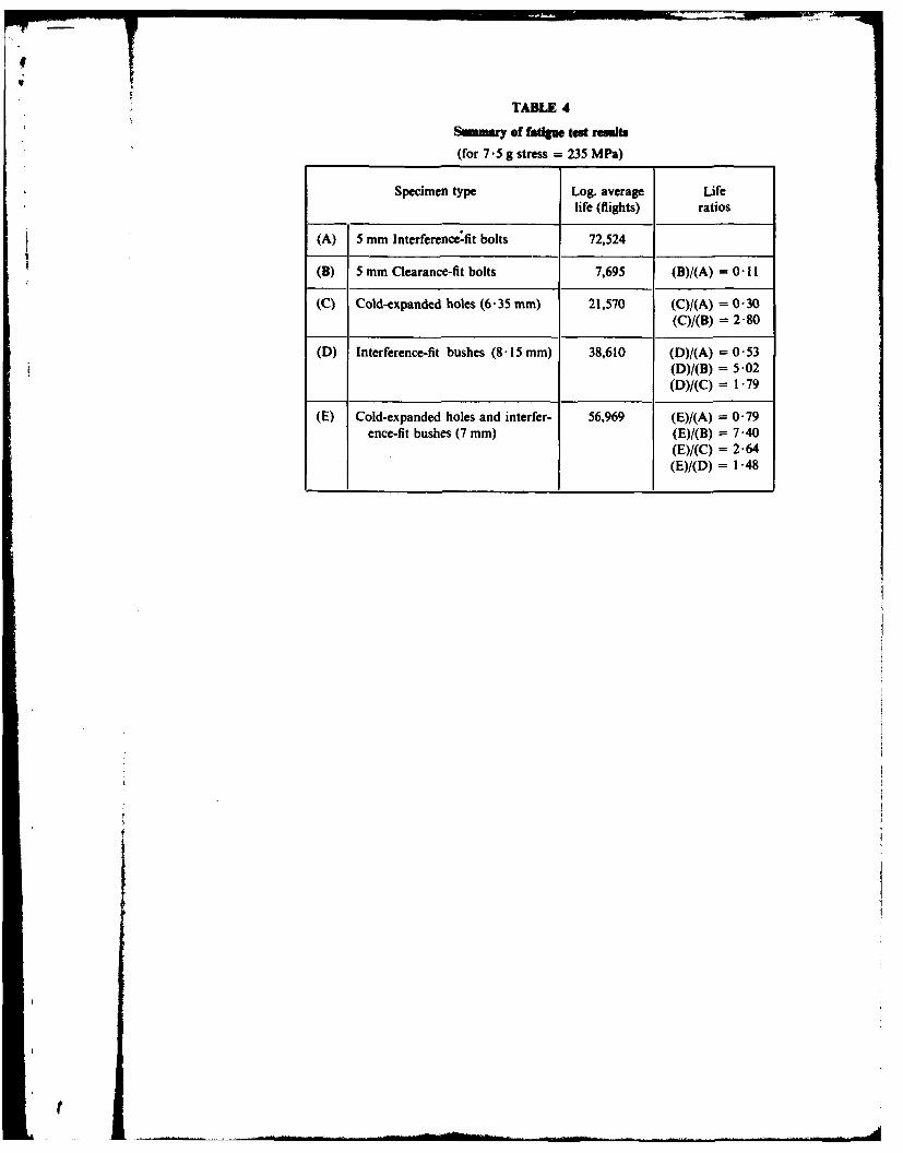
TABLE 4
Summar of fatige test resutsf
(for 7 -5 g stress =235 M Pa)
Specimen type Log. average Life
life (flights) ratios
(A) 5 mm Interference-fit bolts 72,524
(B3) 5 mm Clearance-fit bolts 7,695 (B)/(A) = 0-II
(C) Cold-expanded holes (6 -35 mm) 21,570 (C)/(A) = 0 -30(C)/(B) = 2-80
(D) Interference-fit bushes (8 -15 mm) 38,610 (D)/(A) = 0-53(D)/(B) = 5-02(D)/(C) = 1-79
(E) Cold-expanded holes and interfer- 56,969 (E)/(A) = 0-79ence-fit bushes (7 mm) (E)/(B) = 7-40
(E)/(C) = 2-64(E)/(D) = 1 *48

V7
TABLE 5Sunnary of Frenc Ad Swims test wit Interferec-it bolt, cleane-ft bolt and
COld-expandedl bole sped.... (Refs 7 and 8)
Specimen type Log. average Lifelife (flights) ratios
(AF) 5 mm Interference-fit bolts 67,105
(CF) Cold-expanded holes (5 mm) 27,987 (Cp)/(AF) = 0-42
(As) 6 -3 mm Interference-fit bolts 78,646
(Bs) 6 -3 mm Clearance-fit bolts 9,403 (B8)/(As) = 0 -12
(Cs) Cold-expanded boles (6-3 mm) 40,553 (Cs)/(As) = 0-52Edge margin = 2 (Cs)/(Bs) = 4-31
For French (F 7 .5 g stress = 210 MPa (30,500 psi).
For Swiss (S) 7 -5 g stress =266 M Pa (38,600 psi).
Undercarriage Tn a
bay
Fairing anchor nut *hole (final failure IA.R. L. test *IIstarboard wing) *
No. 12 5 mm bolt hole t* 4
(final failure SWISStest port wing)
Forward .1.Drain plug
I n oardof wing attachment pin
CMain spar
+ 10 mm hex.head shoulder bolt r7 Region of structureI covered by this
+ 8 mm hex.head shoulder bolt I inlvestigation
+ 8 mm countersunk head screwI
6 mm countersunk head screw
+4 5mm hex-head bolt
+ 5 mm countersunk head bolt
+ Rivet
FIG. 1 MIRAGE PORT WING VIEWED FROM LOWER SURFACE

Datum mark
05
1.5 thick skin2024--T3
r 8 14Al alloy
(1)
(5)+
5.0 dia. 17 hcinterferencepakn
10 fit bolts pieceT
48-----Aalo
60All dimenions in mmBWt hole positions in specimen Material: BS.L 168 Alalloyindicated by number in (
FIG.?2 MIRAGE SPAR LOWER FRONT FLANGE FATIGUE SPECIMEN
63.5
61 Direction of extrusion
63.5-
* 1,
'1-' 46
G R26E2
_._ Small specimens: GR3F 1, GR5F1, GR7F1,I,+, IGR19F1, GR20F1, GR21F1, and GR26E3-.. .thickness 19.
Large specimens: GR26E1, and GR26E2 -
R23 L I thickness 25, width 62.5, depth 60.
Bar GR26
FIG. 3 LOCATIONS OF COMPACT TENSION FRACTURE TOUGHNESSSPECIMENS IN EXTRUDED BARS.
II I
7
39
6
.0
2 UE0
1
0
-2
-301110 100 1000
E xceedances Per 100 flIigh ts
FIG. 4 TEST LOADING SPECTRUM FOR 100 FLIGHTS

v
+
. +
+ i+
+0+>. a .n
U) U) .4n..3 ..) d + LU
0 0 + Vo% >- .c+ .+ + 010
C.. M ~ U) M ) In
010U) U)~Z u V u
.40 r. c0 u +r
+ N+ (nQ
0U) 0
U)c a)Lf L
o i 0 0+n
U) 04 uO
0 A U, 0n ______u o~+ (4 + ~+ C4 r n
0 N u r
0! m+ ++ + c
>.~- -. >..0r
u)U U U)) U o-~
0 01 +
'I)+ N'+ IV)+ +
U))
0 E4 U+ 0+
En U) rn t-00 I . 0
C.. 11 > .- " > 11ItDC.) U0l k+u t
w N N ; N0 0 .3 7W~ta u+ u u +u + . +w >- >. >.11 >.11 1
0: uU P ua, ua !(

FIG. 6 DEFORMED ZONES ON FACES OF COLD-EXPANDED HOLE SPECIMEN
1.9 - - - - -- ___
1.8
1.
M1.6
bt 1.25 xm k. log (flights) =4.266 - 7.921 1 lg(SF)S1.2
cn1.1
1.0
0.9
0.85
0.81032 3 5 7 9142 3 4 S 6 7190
Life (flights)
FIG. 7 FATIGUE LIVES OF TYPE (C) COLD-EXPANDED HOLE SPECIMENSAT DIFFERENT STRESS SCALING FACTORS
Ream 'A'diameter
0.700 - -----diaete
Noia 'AIL Dhol Ii
5.2 HoeIa7 295I
Details ofl chamer8. 5.1 29.5'
0.3%
Note1.~ D mtr' itreec0.5t0.5 onhls i2. MaeiltpI0 tils te3. ExenlsraeIrudfns
4. All. imensdiametemm
holdG. 8 _STEEBUSHE
HoleWia
!2A/ I'S Corresponds to innerd ia meter of washer
Specimen no. ,"
~Flights:
2552,4742
Nut faceI %
Specimen no.G R15A
F lights:59,618
Nut face
iExtent of crack after 79, 700
, i I flights (see Table 2)Specimen no.GR22AFlights:
79,700
FIG. 9(a) FRACTURE SURFACES: SPECIMEN TYPE (A: INTERFERENCE - FIT BOLTS(The full lines indicate the approximate extent of fatigue cracking before final failure,while the dotted lines represent the approximate boundaries of the'fiat' arm of the
major crack before the development of shear lips at an advwnedI stop of the crakpropagation.)
Spcmeto

2.41,
Nut face
Specimen no.GR68Flights:5, 642
Nut face
Specimen no./GR3B
Flights:7,399
Nut fae
Specimen no.GR7B
Flights:8,099(see also Fig. I10(d)) '
FIG. 9 (b) FRACTURE SURFACES: SPECIMEN TYPE (B)CLEARANCE - FIT BOLTS
2,4 i's
Nut face
Specimen no.GR2BIFlights:8,742
Nut face
Specimen no.G R5BFlights:9,127
Isee also Fig. 11 (a)) '
Nut face I_________
Specimen no.
F lights:12,942
FIG. 9(b) FRACTURE SURFACES: SPECIMEN TYPE (B)CLEARANCE - FIT BOLTS

2,4 i's
Nut face
Specimen no.GR1 6DF lights:2,362
Nut face __________
Specimen no.GR26DFlights:2,818
Nut face
Specimen no.GRSDFlights:2,913
FIG. 9(c) FRACTURE SURFACES: SPECIMEN TYPE (C)COLD - EXPANDED HOLES

2,4 1,5
Nut face
Specimen no.GR88Flights:3,136
Nut face
Specimen no.GR12BFlIights:3,223
FIG. 9(c) FRACTURE SURFACES: SPECIMEN TYPE (C)COLD - EXPANDED HOLES
2,4 I'S
Nut face
Specimen no.GR6D3
Flights:14,742
Very small crack
Nut face
Specimen no.GR19DFlights: I16,542
Nut face
Specimen no.GR3D IFlights:20,427
FIG. 9(c) FRACTURE SURFACES: SPECIMEN TYPE (C)COLD - EXPANDED HOLES
2,4 1,5
Nut face
I IISpecimen no.GR23D
F Iights: I24,413 \(see also Fig. 10 (c)) I
I
Nut face
I
Specimen no.GR9D I
Flights: I25,813 I(see also Fig. 11 (b)) I I
I I1II!I
Nut face
I.
J1,'Specimen no.GR11B IIFlights:25,842
FIG. 9(c) FRACTURE SURFACES: SPECIMEN TYPE (C)COLD - EXPANDED HOLES

Specimen no.GR2DFlights:I26,781(see also Fig. 11(c)) 1
Nut face
Specimen no.GR1EFlights:24,300(see also Fig. I10(f))
FIG. 9(c) FRACTURE SURFACES: SPECIMEN TYPE (C)COLD - EXPANDED HOLES

2,4 i'sNut face
Specimen no.GR10B
Flights:49,242
-- Nut facej
Specimen no.GR18D
4~ Flights:
COLDD - XADE OE
2,4 i's
Nut fce.
Specimen no.GR20DFlights:64,142
Surface initiationbetween holes 4 and 5 " Nut face
Specimen no.GR4A IFlights:78,041
FIG. 9(c) FRACTURE SURFACES: SPECIMEN TYPE (C)COLD - EXPANDED HOLES
2,4 i's
Nut face
Specimen no.GR17EFlights:27,013
Nut face
Specimen no. ' I IG R20E -
Flights:30,227(see also Fig. 10(c))
N ut face _________________________________________
Specimen no.IGR23EIFlights:41,242 -0~
FIG. 9(d) FRACTURE SURFACES: SPECIMEN TYPE (031INTERFERENCE - FIT BUSHES

2,4 is5Nut face ________
Specimen no.G R 12EF lights:41,542 Planes about
>7mm apart
Nut face
Specimen no.GR25E
Flights:61,342(see also Fig. 10(b))
FIG. 9(d) FRACTURE SURFACES: SPECIMEN TYPE (D)INTERFERENCE - FIT BUSHES

f
2,4 1,5
Specimen no.GR21DFlights:48,042
Nut face
Specimen no.GR7DFlights:54,042(see also Fig. 1l0(a))
Nut face
Specimen no.GR22DFlights:55,542
FIG. 9(e) FRACTURE SURFACES: SPECIMEN TYPE (E)INTERFERENCE - FIT BUSHES IN COLD -EXPANDED HOLES
2,4 1,5
Nut face
Specimen no.
GR11D ._Flights: I63,142
j__I'
Nut facel
Specimen no.GR17D
FlIights: 4
65,899
Small crack at hole 2
FIG. 9(e) FRACTURE SURFACES: SPECIMEN TYPE (E)INTERFERENCE FIT - BUSHES IN COLD - EXPANDED HOLES
f L I- "I - -. ... .
Nut face
(a) Specimen GR7D - type (E) interference -fit bushes in cold-expanded holes
Nut face
(b) Specimen GR25E - type (D) interference -fit bushes
Nut face
(c) Specimen GR20E - type (D) interference -fit bushes
FIG. 10 REPRESENTATIVE FATIGUE FRACTURES
V
Nut face
(d) Specimen GR7B - type (B) clearance -fit bolts
Nut face
(e) Specimen GR23D -type (C) cold -expanded holes
Nut face
(f) Specimen GRIE -type (C) cold -expanded holes (residual static strength test)
FIG. 10 REPRESENTATIVE FATIGUE FRACTURES(

I
Nut face
(a) Specimen GR5B - type (B) clearance -fit bolts
Nut face
(b) Specimen GR9D -type (C) cold -expanded holes
Nut face
(c) Specimen GR2D - type (C) cold -
expanded holes
FIG. 11 SPECIMENS SELECTED FOR CRACK GROWTH MEASUREMENTS
Nut face
$As
'B'
(dI) Specimen GR38 - type (B) clearance-fit bolts, non-failure hole 2
FIG. 11 SPECIMENS SELECTED FOR CRACK GROWTH MEASUREMENTS
I
10
9
8
7 5mm reamed holes 6.35mm C-E holes
6EE
5 GR7B GR9D outerouterinner
0
4 GR5B GR2D outer
outerinner
3
2
GR38 innere-
1 GR9D inner
00 5000 10000 15000 20000 25000 30000
Number of flights, French sequence
I
FIG. 12 CRACK GROWTH CURVES FOR REAMED HOLES AND COLD-EXPANDEDHOLES FROM FRACTOGRAPHIC MEASUREMENTS
'pL

DISTRIBUTION
AUSTRALIA
DEPARTMENT OF DEFENCE
Central OfficeChief Defence ScientistDeputy Chief Defence ScientistSuperintendent, Science and Technology Programmes (I copy)Controller, Projects and Analytical StudiesDefence Science Representative (U.K.) (Doc. Data sheet only)Counsellor, Defence Science (U.S.A.) (Doc. Data sheet only)Defence Central LibraryDocument Exchange Centre, D.I.S.B. (17 copies)Joint Intelligence OrganisationLibrarian H Block, Victoria Barracks. MelbourneDirector General-Army Development (NSO) (4 copies)
Aeronautical Research LaboratoriesDirectorLibrarySuperintendent-StructuresDivisional File-StructuresAuthors: J. Y. Mann
A. S. MachinW. F. LupsonR. A. Pell
G. S. JostG. W. RevillB. C. HoskinJ. M. Finney
Materials Research LaboratoriesDirector/Library
Defence Research CentreLibrary
Navy OfficeNavy Scientific AdviserDirectorate of Naval Aircraft Engineering
Army OfficeArmy Scientific AdviserEngineering Development Establishment, Library
Air Force OfficeAir Force Scientific AdviserDirector General Aircraft Engneering-Air ForceHQ Support Command (SENGSO)
li

f
DEPARTMENT OF DEFENCE SUPPORT
Goveraemt Aircraft FactoriesManagerLibrary
DEPARTMENT OF AVIATION
LibraryFlying Operations and Airworthiness Division
Melbourne, Mr K. R. A. O'BrienCanberra, Mr C. Torkington
STATUTORY & STATE AUTHORITIES AND INDUSTRY
Australian Atomic Energy Commission, DirectorCSIRO
Materials Science Division, LibraryTrans-Australia Airlines, LibraryQantas Airways LimitedSEC of Vic., Herman Research Laboratory, LibraryAnsett Airlines of Australia, LibraryB.H.P.. Melbourne Research LaboratoriesCommonwealth Aircraft Corporation
LibraryMr. K. J. Kennedy (Manager Aircraft Factory No. I)
Hawker de Havilland Aust. Pty Ltd. Bankstown, Library
Universities and CollegesAdelaide Barr Smith LibraryMelbourne Engineering LibraryMonash Hargrave Library
Professor 1. J. Polmear, Materials EngineeringNewcastle LibraryNew England LibrarySydney Engineering LibraryN.S.W. Physical Sciences Library
Metallurgy LibraryQueensland LibraryTasmania Engineering LibraryWestern Australia LibraryR.M.I.T. Library
CANADACAARC Coordinator StructuresInternational Civil Aviation Organization, LibraryEnergy Mines & Resources Dept.
Physics and Metallurgy Research LaboratoriesNRC
Aeronautical & Mechanical Engineering LibraryDivision of Mechanical Engineering, Director
uersities OW Colkg"sToronto Institute for Aerospace Studies

FRANCE
ONERA, Library
INDIA
CAARC Coordinator StructuresDefence Ministry, Aero Development Establishment, LibraryHindustan Aeronautics Ltd, LibraryNational Aeronautical Laboratory, Information Centre
INTERNATIONAL COMMITIEE ON AERONAUTICAL FATIGUE
Per Australian ICAF Representative (25 copies)
ISRAEL
Technion-Israel Institute of TechnologyProfessor J. SingerProfessor A. Buch
JAPAN
National Research Institute for Metals, Fatigue Testing DivisionInstitute of Space and Astronautical Science, Library
UniversitiesKagawa University Professor H. Ishikawa
NETHERLANDS
National Aerospace Laboratory (NLR), Library
UniversitiesTechnological University
of Delft Professor J. Schijve
NEW ZEALAND
Defence Scientific Establishment, LibraryRNZAF, Vice Consul (Defence Liaison)
UniversitiesCanterbury Library
Professor D. Stevenson, Mechanical Engineering
SWEDENAeronautical Research Institute, LibrarySwedish National Defense Research Institute (FOA), Library
SWITZERLAND
Armament Technology and Procurement GroupF + W (Swiss Federal Aircraft Factory)

UNITED KINGDOM
Ministry of Defence, Research, Materials and CollaborationCAARC, Secretary (NPL)Royal Aircraft Establishment
Bedford, LibraryFarnborough, Library
Commonwealth Air Transport Council SecretariatAdmiralty Marine Technology Establishment, LibraryNational Gas Turbine Establishment
Director, Pyestock NorthNational Physical Laboratory, LibraryNational Engineering Laboratory, LibraryBritish Library, Lending DivisionCAARC Coordinator, StructuresFulmer Research Institute Ltd, Research DirectorMotor Industry Research Association, DirectorRolls-Royce Ltd
Aero Division Bristol, LibraryWelding Institute, LibraryBritish Aerospace
Hatfield-Chester Division, LibraryBritish Hovercraft Corporation Ltd, LibraryShort Brothers Ltd, Technical Library
Universities and CollegesBristol Engineering LibraryNottingham Science LibrarySouthampton LibraryStrathclyde LibraryCranfield Inst. of
Technology LibraryImperial College Aeronautics Library
UNITED STATES OF AMERICA
NASA Scientific and Technical Information FacilityApplied Mechanics ReviewsMetals InformationThe John Crerar LibraryThe Chemical Abstracts ServiceBoeing Co.
Mr R. WatsonMr J. C. McMillan
Lockheed-California CompanyLockheed GeorgiaMcDonnell Aircraft Company, LibraryNondestructive Testing Information Analysis Center
Universities and CollegesIowa Professor R. I. StephensIllinois Professor D. C. DruckerMassachusetts Inst.
of Technology M.I.T. Libraries
SPARES (15 copies)
TOTAL (178 copies)
t

Department of Defence Support
DOCUMENT CONTROL DATA
I. a. AR No. I. b. Establishment No. 2. Document Date 3. Task No.AR-002-973 ARL-STRUC-NOTE-490 August, 1983 DST 79/130
4. Title 5. Security 6. No. PagesTHE USE OF INTERFERENCE-FIT BOLTS OR a. document 23BUSHES AND HOLE COLD EXPANSION FOR Unclassifiedb. title c. abstract 7. No. RefaINCREASING THE FATIGUE LIFE OF THICK- U U 47
SECTION ALUMINIUM ALLOY BOLTED JOINTS
8. Author(s) 9. Downgrading InstructionsJ. Y. Mann, A. S. Machin, W. F. Lupson and R. A. Pell
10. Corporate Author and Address II. Authority (as appropriate)Aeronautical Research Laboratories a. Sponsor c. DowngradingP.O. Box 4331, MELBOURNE, Vic. 3001 b. Security d. Approval
12. Secondary Distribution (of this document
Approved for public release
Overseas enquirers outside stated limitations should be referred through ASDIS, Defence Information ServicesBranch, Department of Defence, Campbell Park, CANBERRA, ACT, 2601.13. a. This document may be ANNOUNCED in catalogues and awareness services available to...
No limitations
13. b. Citation for other purposes (i.e. casual announcement) may be (uee) unrestricted (ee)-e .
14. Descriptors 15. COSATI Group
Fatigue (materials) Fasteners (interference) 1113Bolted joints Interference fitting 1103Holes (openings) BushingsCold working Aluminium alloysAircraft structures
16. AbstractThe detection offatigue cracks at bolt holes in the main spar of the Mirage III wing during full-scalefatigue tests led to a requirement for refurbishment procedures to extend the fatigue lives at a numberof critical locations. One of these, which is covered by this investigation, was the spar lower frontflange. Flight-by-flight fatigue tests have been carried out to determine the relative fatigue perform-ance of aluminium alloy bolted joint specimens of 28 mm thickness incorporating close-fit bolts,interference-fit bolls (0 "4 %), hole cold-expansion (3 %), interference-fit steel bushes (0" 3 %) and acombination of cold-expansion and interference-fit bushes.
Compared with joints assembled with close-fit bolts in reamed holes, the ratios of the lives ofspecimens incorporating interference-fit bolts, interference-fit bushes and cold-expanded bolt holeswere about 9:1,5: 1 and3: / respectively. Furthermore, specimens with holes cold-expandedfollowedby the installation of interference-fit bushes resulted in a greaterfatigue life than with interference-fitbushes alone.
f
This pge is to be used to record information which Is required by the Establishment for its own use butwhich will not be added to the DISTIS data base unless specifically requested.
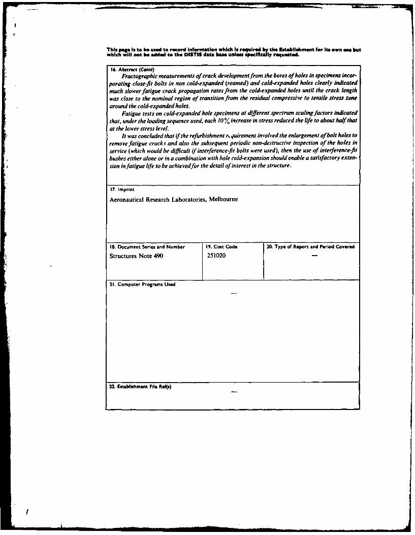
16. Abstract (Contd)Fractographic measurements of crack development from the bores of holes in specimens incor-
porating close-fit bolts in non cold-expanded (reamed) and cold-expanded holes clearly indicatedmuch slower fatigue crack propagation rates from the cold-expanded holes until the crack lengthwas close to the nominal region of transition from the residual compressive to tensile stress zonearound the cold-expanded holes.
Fatigue tests on cold-expanded hole specimens at different spectrum scaling factors indicatedthat, under the loading sequence used, each 10% increase in stress reduced the life to about half that
at the lower stress level.It was concluded that if the refurbishment rnquirement involved the enlargement of bolt holes to
remove fatigue cracks and also the subsequent periodic non-destructive inspection of the holes in
service (which would be difficult if interference-fit bolts were used), then the use of interference-fitbushes either alone or in a combination with hole cold-expansion should enable a satisfactory exten-sion in fatigue life to be achievedfor the detail of interest in the structure.
17. Imprint
Aeronautical Research Laboratories, Melbourne
18. Document Series and Number 19. Cost Code 20. Type of Report and Period Covered
Structures Note 490 251020
21. Computer Programs Used
22. Establishment File Ref(s)
I