METRO HYD BOOK.pub - Metro Hydraulic Jack Co. · PDF file6 DS SIX PORT—TWO POSITION...
12
METRO “When The Pressure’s On…” “When The Pressure’s On…” Our High Quality Components Our High Quality Components Make the Difference! Make the Difference!
Transcript of METRO HYD BOOK.pub - Metro Hydraulic Jack Co. · PDF file6 DS SIX PORT—TWO POSITION...

METRO “When The Pressure’s On…”“When The Pressure’s On…”
Our High Quality Components Our High Quality Components Make the Difference!Make the Difference!

2
Contents
Kits for Directional Control Valves Code, Description and Price 3 D Series Directional Control Valves
Features, Options & Specifications 4
DS Six Port—Two Position Double Selector Valve 6 MDS Six Port—Two Position Double Selector Valve 7 MV, SV and MSL Selector Valves 8 D-601 Double Pilot Operated Lock Valves 9 Double Lock Valve 407, 408 and 409 10 Single Lock Valve 411 and 412 10 Check Valve FC and FCF 11 Restrictor Valve FR and FRF 11 Relief Valve RV and RVF 11
METRO MACHINE & ENGINEERING 952-259-3623

3
Kits for Directional Control Valves
(CODE) 830-00-001 830-00-002 830-00-003 830-00-004 830-00-005 830-00-006 830-00-007 830-00-008 830-00-009 830-00-010 830-00-019 830-00-013 830-00-014 830-00-015 830-00-016 830-00-017 830-00-023 830-00-024 830-00-121-S H Handle Kit J Handle Kit K Handle Kit
DESCRIPTION
Seal Kit (1 Spool Valve) Seal Kit (2 Spool Valve) Seal Kit (3 Spool Valve) Handle Linkage Kit Handle Kit, 1 Straight Handle Float Spool Kit Spring Center Kit 3 Position Detent Kit Load Check Kit Closed Center Kit Relief Kit, 500 PSI Relief Kit, 1000 - 1499 PSI Relief Kit, 1500 - 1999 PSI Relief Kit 2000 - 2499 PSI Relief Kit 2500 - 3000 PSI NO Relief Kit 2-Position Detent - Spool In 2-Position Detent - Spool Out Power Beyond Plug, w/seals 1-Spool Valve 2-Spool Valve 3-Spool Valve
Other parts available upon request.
METRO MACHINE & ENGINEERING 952-259-3623

4
D SERIES 6 GPM DIRECTIONAL CONTROL VALVES 1, 2 & 3 SPOOL
FEATURES • One piece mono-block body construction using high tensile
cast iron.
• Hard chrome plated and precision fitted spools. • Easy installation with inlet and outlet ports on same end. • Load check for each spool prevents accidental load drop
(omitted with motor spool). • Standard open center valving.
OPTIONS • Variety of spool configurations. • Spring centered or detented. • Power beyond or closed center adapter plugs. • Handle assemblies. • “MULTI” VALVE, special 1 spool 4 way to 3 way conver-
sion valve.
Pressure Rating Temperature Range
3000 PSI (207 Bar)
-22° to + 194° F -30° to + 90° C
SPECIFICATIONS
ORDER EXAMPLE FOR D2DF1T2J
D2 D
SPOOL 1 F 1
J
SPOOL 2 T 2
SPOOL 3
Basic Valve Function
(With Load Checks)
Relief Setting (Cracking Pressure)
Spool Spring Return
Power Beyond Option
Handle Option
Repeat For Each Spool
D1 1 Spool Valve
M = MOTOR (Load Check
Omitted)
1 = Spring Centered with One Position
Detent 2 = Standard Spring
Centered Type
Omit if Not Required
Omit if No Handle Assembly Required
D2 2 Spool Valve
T = TANDEM 3 = 3 Position Detent (no spring)
4 = Micro Switch (incorporates spring
centering)
P = Power Beyond
H = (1) Complete Handle
Assy. (not attached)
D3 3 Spool Valve
Y = 3 WAY 5 = 2 Position Detent (neutral/spool in)
6 = 2 Position Detent (neutral/spool out)
7 = 2 Position Detent (spring offset)
S = Closed Center Plug
J = (2) Complete Handle
Assy. (not attached)
CDI “Multi” Valve
special 1 spool 4 way to 3 way
conversion valve
F = FLOAT (specify
spring return option “1” with
this spool
8 = Special, Detent Spool In, Spring Return
Out 9 = Special, Detent Spool Out, Spring
Return In
K = (3) Complete Handle
Assy. (not attached)
0 = No Relief
RELIEF SETTING
A = 1000 PSI
B = 1500 PSI
C = 2000 PSI
D = 2500 PSI
E = 3000 PSI
ORDER EXAMPLE
ORDER PROCEDURES When developing the complete part number, copy all codes required. Note: Other relief pressure settings, spool configuration, or port sizes available upon special order. Please consult factory.
Complete part num-ber of example D2DF1T2J Float spool must always be in first or third position.
METRO MACHINE & ENGINEERING 952-259-3623
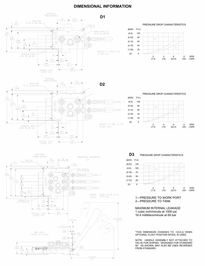
DIMENSIONAL INFORMATION
D2
D1
D3
(BAR)
(6.9)
(5.52)
(4.14)
(2.76)
(1.38)
(0)
P.S.I
100
80
60
40
20
0 2
(7.5) 4
(15) 6
(22.5) 8
(30) GPM L/MIN
2 (7.5)
4 (15)
6 (22.5)
8 (30)
GPM L/MIN
(BAR)
(6.9)
(5.52)
(4.14)
(2.76)
(1.38)
(0)
P.S.I
100
80
60
40
20
0
P.S.I
125
100
75
50
25
0
(BAR)
(8.63)
(6.9)
(5.18)
(3.45)
(1.73)
(0)
2 (7.5)
4 (15)
6 (22.5)
8 (30)
GPM L/MIN
PRESSURE DROP CHARACTERISTICS
PRESSURE DROP CHARACTERISTICS
PRESSURE DROP CHARACTERISTICS
1—PRESSURE TO WORK PORT 2—PRESSURE TO TANK MAXIMUM INTERNAL LEAKAGE 1 cubic inch/minute at 1000 psi 16.4 milliliters/minute at 69 bar *THIS DIMENSION CHANGES TO .12/(3.2) WHEN OPTIONAL FLOAT POSITION SPOOL IS USED. NOTE: HANDLE ASSEMBLY NOT ATTACHED TO VALVE FOR SHIPING. DESIGNED FOR STANDARD 90° AS SHOWN, MAY ALSO BE USED REVERSED FROM STANDARD.

6
DS SIX PORT—TWO POSITION DOUBLE SELECTOR VALVES
DESCRIPTION The DS is a two position, double selector valve which directs the flow of hydraulic fluid to two separate hydraulic circuits. This allows operation of two double acting cylinders with one four-way control valve or four single-acting cylinders with two-three-way control valves. The Metro DS two position double selector valve is of the open-crossover type. When the spool is moved and one pair of outlet ports start to close, the other pair of outlet ports start to open.
PORTING KEY (Viewed from Handle End) Standard Open Crossover: (See drawing upper right) • With spool pushed into housing, port D and E are con-
nected to each other, port C and A are connected to each other.
• With spool pulled out of housing, port D and F are con-nected to each other, port C and B are connected to each other.
SERIES PARALLEL (Available on Special Order) • With spool pushed into housing, port C is connected to
port A and B, port D is connected to E and F. • With spool pulled out of housing, port C is connected to
port A and port D is connected to port F, port B is con-nected to port E.
PORTING KEY
SPECIFICATIONS
*LEVER ASSEMBLY NOT ATTACHED TO VALVE FOR SHIPPING
Flow Capacity
Pressure Rating
Temperature Range
Weight
20 GPM 75 (L/MIN)
3000 PSI (207 Bar)
-22° to + 194° F -30° to + 90° C
4 lbs 4 oz (1.92 kg)
DS 04 - 20 DR
Valve Model
Number
Port Size
Spool Type
Options
Spool Actuator Options
Spool Return Options
DS Double Selector
Valve
02= 1/4 -18 NPT 03= 3/8 -18 NPT 04= 1/2 -14 NPT 06= 9/16 -18 #6 SAE 08= 3/4 -16 #8 SAE
= Standard Crossover
Type
P = Optional Parallel Type
(available on special order)
Other Special Spool Types
Available on Special Order
10= No Actuator 20= Knob 30= Lever* 40= Clevis
Omit if Not
Required
DR= Spring Return
ORDERING INSTRUCTIONS
DIMENSIONAL INFORMATION
5 (18)
10 (37)
15 (56)
20 (75)
25 (94)
P.S.I
125
100
75
50
25
0
(BAR)
(8.6)
(6.9)
(5.2)
(3.5)
(1.7)
(0)GPM L/MIN
PRESSURE DROP CHARACTERISTICS
Standard
Series Parallel
METRO MACHINE & ENGINEERING 952-259-3623

7
DESCRIPTION The MDS is a two position, double selector valve which directs the flow of hydraulic fluid to two separate hydraulic circuits. This allows operation of two double acting cylinders with one four-way control valve or four-single acting cylinders with two-three-way control valves. The Metro MDS two position double selector valve is of the open-crossover type. When the spool is moved and one pair of outlet ports start to close, the other pair of outlet ports start to open.
PORTING KEY (Viewed from Handle End) Standard Open Crossover: (See drawing upper right) • With spool pushed into housing, port D and E are con-
nected to each other, port C and A are connected to each other.
• With spool pulled out of housing, port D and F are con-nected to each other, port C and B are connected to each other.
SERIES PARALLEL (Available on Special Order) • With spool pushed into housing, port C is connected to
port A and B, port D is connected to E and F. • With spool pulled out of housing, port C is connected to
port A and port D is connected to port F, port B is con-nected to port E
*LEVER ASSEMBLY NOT ATTACHED TO VALVE FOR SHIPPING
PORTING KEY DIMENSIONAL INFORMATION
MDS SIX PORT—TWO POSITION DOUBLE SELECTOR VALVES
MDS 08 - 50 SR
Valve Model
Number
Port Size
Spool Type
Options
Spool Actuator Options
Spool Return Options
MDS Double Selector
Valve
04= 1/2 -14 NPT 05= 3/4 -14 NPT 06= 1 -14 NPT 08= 3/4 -16 #8 SAE 10= 7/8 -14 #10 SAE 12= 1-1/16 -12 #12 SA 14= 1-3/16 -12 #14 SAE 16= 1-5/16 -12 #16 SAE
(-) Standard Crossover
Type
P = Optional Parallel Type
10= No Actuator 20= Knob 30= Lever* 40= Clevis 50= Pilot Oper-ated (hydraulically)
Omit if Spring Return Not Required
SR= Spring Return
(casted)
RD= Spring Return
(stamped)
ORDERING INSTRUCTIONS
Flow Capacity
Pressure Rating
Temperature Range
Weight
30 GPM 114 (L/MIN)
3000 PSI (207 Bar)
-22° to + 194° F -30° to + 90° C
10 lbs (4.5 kg)
SPECIFICATIONS
GPM L/MIN
(BAR) P.S.I.
(0) 0
(2.07) 30
(.69) 10
(1.38) 20
(2.76) 40
40 (151)
20 (75)
30 (113)
10 (37)
PRESSURE DROP CHARACTERISTICS
Standard
Series Parallel
METRO MACHINE & ENGINEERING 952-259-3623

8
MV, SV AND MSL SELECTOR VALVES
DESCRIPTION The Metro MV, SV and MSL Selector Valves with the standard spool may be used as an open or closed three way valve where flow is directed to an actuator i.e., single-acting cylinder in one position or flow from the actuator is allowed to return to tank, in the other position. This valve may also be used as a three way diverter valve where inlet flow is directed to either of the two ports. The standard spool has an open crossover so, as the spool is being shifted, one outlet port begins to close and the other outlet port begins to open.
OPTIONS A closed crossover spool is available upon special order for the MV and SV selector valves. Here, as the spool is being shifted, flow is not allowed to crossover between outlet ports because flow is closed to the outlet ports for a moment while shifting. An optional float spool is available for the selector valves where all ports are either open to each other or closed to each other. This option is designed to allow cylinders to float or motors to free-wheel in such equipment as snowplows, combine headers, mower attachments, etc.
ORDERING INSTRUCTIONS
MV 04
Model Number
Port Size
Options Other Than Standard
Spool With Knob
Spool Actuator
Location Op-tions
Return Options
MV or SV Up to 20 GPM (75.8 L/MIN)
03= 3/8 -18 NPT 04= 1/2 -14 NPT 06= 9/16 -18 #6 SAE 08= 3/4 -16 #8 SAE
10= No Knob 80= Float Spool w/Knob 81= Standard Spool w/Clevis 82= Standard Spool w/Spring Return 83= Float Spool w/Clevis 85= Float Spool w/Spring Return 89= Closed Center w/Knob & Spring Return
R= Reverse Spool
*Lever assembly
for MV model available upon
request
See spool options
MSL Up to 40 GPM (151.6 L/MIN)
04= 1/2 -14 NPT 05= 3/4 -14 NPT 06= 1 -NPT 08= 3/4 -16 #8 SAE 10= 7/8 -14 #10 SAE 12= 1-1/16 -12 #12 SAE 16= 1-5/16 -12 #16 SAE
F= Float w/Knob 30= Handle 40= Standard w/Clevis 50= Pilot Operated
R= Reverse Spool
SR= Spring Return
SPECIFICATIONS
Pressure Rating
Temperature Range
3000 PSI (207 Bar)
-22° to + 194° F -30° to + 90° C
PRESSURE DROP CHARACTERISTICS
GPM L/MIN
10 (37)
(BAR) P.S.I.
(0) 0
(1.73) 25
(3.45) 50
(5.18) 75
(6.9) 100
20 (75)
30 (113)
40 (151)
SV
MSL
MV
METRO MACHINE & ENGINEERING 952-259-3623

9
D-601 DOUBLE PILOT OPERATED LOCK VALVES
Flow Capacity
Pressure Rating
Temperature Range
Weight
See Performance Graph
2500 PSI
-22° to + 194° F -30° to + 90° C
3 lbs 4 oz (1.47 kg)
SPECIFICATIONS The D-601 Lock Valve is designed to lock a cylinder or part of a circuit while a directional control valve is in the neutral position, specifically for applications where directional control valve leakage could adversely affect the performance of the system. In addition, this lock valve also has built in integral relief's for thermal or ex-cess pressure shocks on the locked part of a circuit. With the directional control valve in the neutral position, flow from both ends of a cylinder is locked by the D-601 Lock Valve. When the directional control valve is activated, flow is directed to one side of the valve unseating the ball check on that side. This al-lows pilot pressure to open the poppet on the opposite side of the valve and allow flow to return to tank. The pilot pressure required to unlock the load is approximately 20% of the difference between the internal relief setting and the load induced pressure. 1. Prevents load from dropping faster than fluid is supplied to
the actuator by the pump. 2. Locks actuator in selected position when no motion is de-
sired. 3. Relieves excess pressure on system caused by load or ther-
mal expansion. 4. Provides an emergency manual release for lowering load in
case of power failure. 5. Requires less power when load is being raised or lowered. 6. Permits smooth movement and eliminates actuator chatter or
cavitations. 7. Prevents load drifting due to directional valve leakage.
APPLICATION A pilot operated check valve (lock valve) should be incorpo-rated in every loader, outrigger, back-hoe, work platforms.
ORDERING INSTRUCTIONS
D-601 08
Model Number Port Size
D-601 08 - 3/4 16 #8 SAE
GPM L/MIN
15 (56)
6 (22)
9 (34)
12 (45)
3 (11)
(34.5) 500
(41.4) 600
(27.6) 400
(20.7) 300
(0) 0
(13.8) 200
(6.9 100
(BAR) P.S.I. PRESSURE DROP CHARACTERISTICS
1. Valve Port to Cylinder Port 2. Cylinder Port to Valve Port
METRO MACHINE & ENGINEERING 952-259-3623

10
407, 408, 409— DOUBLE LOCK VALVE
411, 412— SINGLE LOCK VALVE
OPERATION With the directional control valve in the neutral position, flow from both ends of a cylinder is blocked, locking the cylinder piston in position by the Double Lock Valve. When the directional control valve is shifted to direct flow to one side of the cylinder, pressure opens the check ball and simultaneously moves the piston over to the opposite side of the valve opening this check ball allowing free flow return to the directional control valve. The 407 lock valve has two adjustable flow controls, and the 408 has one adjustable flow control which, by adjusting in or out, changes the pressure drop in the valves. This in most cases, smoothes our pulsations and eliminates valve chatter. Single Lock Valves are also available. The 411 single lock is non-adjustable and the 412 single lock is adjustable.
APPLICATION Typical applications are loaders, outriggers, back hoes, cranes, fork lifts, work platforms, hydraulic winches, land planes, wing lifts, gauge wheels or any application where loads must be held in neutral position. A 4-way control valve is required for all lock valve circuits, in-cluding single-acting cylinders, in order to apply unlocking pressure to the pilot circuit. The position pilot ratio is 3:1. The amount of pressure required in the pilot circuit of the valve to unlock a single-acting cylinder is 30% of the locked pres-sure. The amount of pressure required in the pilot circuit of the valve to unlock a single-acting cylinder is a function of cylinder ar-eas and trapped pressure. When the base end of the cylinder is locked use this formula for calculating the unlocking pressure. Pressure on the rod end Unlocking pressure = 3 - Cylinder area - Rod area Cylinder area When the rod end of the cylinder is locked use this formula. Pressure on the base end Unlocking pressure = 3 - Cylinder area
CAUTION: Note that when the rod end of a double-acting cylinder is locked, if the rod diameter exceeds approxi-mately .75 times the cylinder diameter, unlocking pressure becomes excessive.
Model Number Port Size
407 Double 408 Double 409 Double 411 Single 412 Single
02= 1/4 -18 NPT 03= 3/8 -18 NPT 04= 1/2 -14 NPT 05= 3/4 -14 NPT 06= 9/16 -18 #6 SAE 08= 3/4 -16 #8 SAE 10= 7/8 -14 #10 SAE
SPECIFICATIONS
Flow Capacity
Pressure Rating
Temperature Range
Weight
See Performance Graph
3000 PSI (207 Bar)
-22° to + 194° F -30° to + 90° C
407 2 lbs. 8 oz. (1.09 kg.)
408
2 lbs. 6 oz. (1.07 kg.)
409
2 lbs. 4 oz. (1.02 kg.)
411
2 lbs. 1 oz. (1.00 kg.)
412
2 lbs. 3 oz. (1.01 kg.)
ORDERING INSTRUCTIONS
DESCRIPTION The Double Lock valves are designed to lock a cylinder or part of a circuit while a directional control valve is in the neutral position. Designed for applications where directional control valve leakage could adversely affect the performance of the system.
409 408
GPM L/MIN
4 (15)
8 (30)
12 (45)
16 (60)
PRESSURE DROP CHARACTERISTICS
20 (75)
(0) 0
(BAR) P.S.I.
(13.8) 200
(20.7) 300
(27.6) 400
(34.5) 500
(6.9) 100
1. Valve Port to Cylinder Port 2. Cylinder Port to Valve Port
METRO MACHINE & ENGINEERING 952-259-3623

11
FC, FCF— CHECK VALVE
FR, FRF— RESTRICTOR
RV, RVF— RELIEF VALVE
ORDERING INSTRUCTIONS
DESCRIPTION The model FC-FCF Check Valve, FR-FRF Restrictor (Throttle) Valve, RV-RVF Relief Valve series of inline valves are available in a variety of sizes. These valves will operate satisfactorily when mounted inline in any position. The FC,FR and RV are male/female design whereas the FCF, FRF and RVF are female/female design.
APPLICATION DATA The FC-FCF Check Valves allow free flow in one direction and checked flow in the opposite direction. Cracking pressure is 1 psi (.07 bar). The FR-FRF Restrictor (throttle) Valve allows free flow in one direction and restricted flow in the opposite direction. Applica-tions include accurate control of a double acting cylinder by pressurizing both sides of the piston, reducing cavitations of cylinders and motors or speed control of cylinders and motors. The RV-RVF Relief Valves provide an inexpensive, but reliable fast acting relief protection in a hydraulic circuit.
FR 50 -062
Model Number Port Size Orifice Size or Relief Setting
FC FR RV FCF FRF RVF
08 38 40 50 60
Orifice size for restrictor valves only
Relief setting for relief
valve only
Pressure Rating
Temperature Range
Relief Valve
Pressure Settings
Number Size Number Size
3000 PSI (207 Bar)
-22° to + 194° F
-30° to + 90° C
-046 -062 -078 -093 -109
3/64 1/16 5/64 3/32 7/64
-125 -140 -156 -187 -250
1/8 9/64 5/32 3/16 1/4
1 -500 PSI (standard)
501 -1200
PSI 1201 -2500
PSI
Restrictor Valve Orifice Sizes
Port Sizes
A Length Inches (mm)
B Hex Size Inches (mm)
C Thread (Both Ends)
D Thread Length Inches (mm)
E Weight
All dimensions common for: FCF, FRF & RV
08 38 40
50 60
3.0 (76.2) 3.0 (76.2) 3.0 (76.2)
3.0 (76.2) 3.38 (85.7)
1.12 (28.6) 1.00 (25.4) 1.06 (26.9)
1.06 (26.9) 1.38 (34.9)
3/4 -16 SAE #8 3/8 -18 NPT 3/8 -18 NPT male To 1/2 -14 NPT female 1/2 -14 NPT 3/4 -14 NPT
.44 (11.2)
.75 (19.1)
.75 (19.1)
.81 (20.6)
.81 (20.6)
8 oz. (.23 kg.) 8 oz. (.23 kg.) 9 oz. (.26 kg.)
9 oz. (.26 kg.) 1 lb. (.45 kg.)
08 38 40
50 60
3.0 (76.2) 3.0 (76.2) 3.0 (76.2)
3.0 (76.2) 3.63 (92.2))
1.12 (28.6) 1.00 (25.4) 1.06 (26.9)
1.06 (26.9) 1.38 (34.9)
3/4 -16 SAE #8 3/8 -18 NPT 3/8 -18 NPT one end 1/2 -14 NPT other 1/2 -14 NPT 3/4 -14 NPT
9 oz. (.26 kg.) 9 oz. (.26 kg.)
10 oz. (.28 kg.)
10 oz. (.28 kg.) 1 lb. 3 oz. (.54 kg.)
All dimensions common for: FC, FR & RVF
SPECIFICATIONS
(BAR) P.S.I.
GPM L/MIN
20 (75)
25 (94)
30 (113)
35 (132)
40 (151)
5 (18)
10 (37)
15 (56)
(120.7) 1750
(103.4) 1500
(86.2) 1250
(68.9) 1000
(51.7) 750
(34.5) 500
(17.2) 250
FLOW THRU RESTRICTED ORIFICE
METRO MACHINE & ENGINEERING 952-259-3623

Metro has over five decades of engineering excel-lence in the design, manufacture and marketing of hydraulic components for industrial, mobile and agri-cultural markets. Special requirements in valve design, manifolds or modification to Metro’s standard product to meet your specific needs will gladly be quoted upon re-quest.
Orders & Correspondence To:
LIMITED WARRANTY
The Company, warranties the products it manufactures against defective workmanship and/or materials for a period of one year from the date of sale to the original customer, provided written notice of the defect is received by the Company during said period. The warranty is limited to repair or exchange of the product at the sellers option. No obligation is assumed for the repair or exchange of any product rendered defective or damaged through normal wear or improper application, handling or use. No other liability, ex-pressed or implied, is assumed by the Company. This warranty is in lieu of all other warranties, expressed or implied.