![Bericht zu PM10-Tagesmittelwerten und Überschreitungen …...28.04.2011 PM10 [µg/m³] 1 58 05.11.2011 PM10 [µg/m³] 5 62 12.11.2011 PM10 [µg/m³] 3 102 23.11.2011 PM10 [µg/m³]](https://static.fdocuments.net/doc/165x107/5feb2fd0c3ceb232dc68d90f/bericht-zu-pm10-tagesmittelwerten-und-oeberschreitungen-28042011-pm10-gm.jpg)
Method IO-1.3 - Determination of PM10 in Ambient Air Using ...
47
EPA/625/R-96/010a Compendium of Methods for the Determination of Inorganic Compounds in Ambient Air Compendium Method IO-1.3 DETERMINATION OF PM 10 IN AMBIENT AIR USING A CONTINUOUS RUPPRECHT AND PATASHNICK (R&P) TEOM® PARTICLE MONITOR Center for Environmental Research Information Office of Research and Development U.S. Environmental Protection Agency Cincinnati, OH 45268 June 1999
Transcript of Method IO-1.3 - Determination of PM10 in Ambient Air Using ...

EPA/625/R-96/010a
Compendium of Methods for the Determination of Inorganic Compounds
in Ambient Air
Compendium Method IO-1.3
DETERMINATION OF PM10 IN AMBIENT AIR USING A CONTINUOUS RUPPRECHT AND PATASHNICK (R&P)
TEOM® PARTICLE MONITOR
Center for Environmental Research Information Office of Research and Development U.S. Environmental Protection Agency
Cincinnati, OH 45268
June 1999

Method IO-1.3
Acknowledgments
This Method is a part of Compendium of Methods for the Determination of Inorganic Compounds in Ambient Air (EPA/625/R-96/010a), which was prepared under Contract No. 68-C3-0315, WA No. 2-10, by Midwest Research Institute (MRI), as a subcontractor to Eastern Research Group, Inc. (ERG), and under the sponsorship of the U.S. Environmental Protection Agency (EPA). Justice A. Manning, John O. Burckle, Scott Hedges, Center for Environmental Research Information (CERI), and Frank F. McElroy, National Exposure Research Laboratory (NERL), all in the EPA Office of Research and Development, were the project officers responsible for overseeing the preparation of this method. Other support was provided by the following members of the Compendia Workgroup:
• James L. Cheney, U.S. Army Corps of Engineers, Omaha, NE • Michael F. Davis, U.S. EPA, Region 7, KC, KS • Joseph B. Elkins Jr., U.S. EPA, OAQPS, RTP, NC • Robert G. Lewis, U.S. EPA, NERL, RTP, NC • Justice A. Manning, U.S. EPA, ORD, Cincinnati, OH • William A. McClenny, U.S. EPA, NERL, RTP, NC • Frank F. McElroy, U.S. EPA, NERL, RTP, NC • William T. "Jerry" Winberry, Jr., EnviroTech Solutions, Cary, NC
This Method is the result of the efforts of many individuals. Gratitude goes to each person involved in the preparation and review of this methodology.
Author(s)
• Erich Rupprecht, Rupprecht and Patashnick, Albany, NY • William T. "Jerry" Winberry, Jr., EnviroTech Solutions, Cary, NC
Peer Reviewers
• David Brant, National Research Center for Coal and Energy, Morgantown, WV • John Glass, SC Department of Health and Environmental Control, Columbia, SC • Jim Cheney, U.S. Army Corps of Engineers, Omaha, NE • Charles Rodes, Research Triangle Institute, RTP, NC • Danny France, U.S. EPA, Region 4, Athens, GA • David Harlos, Environmental Science and Engineering, Gainesville, FL • Jim Tisch, Graseby, Cleves, OH • Michael B. Meyer, Rupprecht and Patashnick, Albany, NY • Richard Shores, Research Triangle Institute, RTP, NC • Laureen Drees, U.S. EPA, NRMRL, Cincinnati, OH
ii

DISCLAIMER
This Compendium has been subjected to the Agency's peer and administrative review, and it has been approved for publication as an EPA document. Mention of trade names or commercial products does not constitute endorsement or recommendation for use.
iii

Method IO-1.3 Determination of PM10 in Ambient Air
Using a Continuous Rupprecht and Patashnick (R&P) TEOM® Particle Monitor TABLE OF CONTENTS
Page
1. Scope . . . . . . . . . . . . . . . . . . . . . . . . . . . . . . . . . . . . . . . . . . . . . . . . . . . . . . . . 1.3-1 2. Applicable Documents . . . . . . . . . . . . . . . . . . . . . . . . . . . . . . . . . . . . . . . . . . . . . 1.3-3
2.1 ASTM Standards . . . . . . . . . . . . . . . . . . . . . . . . . . . . . . . . . . . . . . . . . . . . 1.3-3 2.2 Other Documents . . . . . . . . . . . . . . . . . . . . . . . . . . . . . . . . . . . . . . . . . . . . 1.3-3
3. Summary of Method . . . . . . . . . . . . . . . . . . . . . . . . . . . . . . . . . . . . . . . . . . . . . . 1.3-3 4. Significance . . . . . . . . . . . . . . . . . . . . . . . . . . . . . . . . . . . . . . . . . . . . . . . . . . . . 1.3-4 5. Definitions . . . . . . . . . . . . . . . . . . . . . . . . . . . . . . . . . . . . . . . . . . . . . . . . . . . . . 1.3-5 6. Interferences . . . . . . . . . . . . . . . . . . . . . . . . . . . . . . . . . . . . . . . . . . . . . . . . . . . 1.3-5 7. Apparatus . . . . . . . . . . . . . . . . . . . . . . . . . . . . . . . . . . . . . . . . . . . . . . . . . . . . . 1.3-6
7.1 TEOM® 1400a Control Unit . . . . . . . . . . . . . . . . . . . . . . . . . . . . . . . . . . . . . 1.3-6 7.2 TEOM® 1400a Sensor Unit . . . . . . . . . . . . . . . . . . . . . . . . . . . . . . . . . . . . . 1.3-6 7.3 TEOM® Sensor/Preheater Assembly . . . . . . . . . . . . . . . . . . . . . . . . . . . . . . . 1.3-7 7.4 TEOM® PM10 Inlet . . . . . . . . . . . . . . . . . . . . . . . . . . . . . . . . . . . . . . . . . . . 1.3-7 7.5 TEOM® Flow Splitter Assembly . . . . . . . . . . . . . . . . . . . . . . . . . . . . . . . . . . 1.3-7 7.6 Electric and Air Cable Assembly . . . . . . . . . . . . . . . . . . . . . . . . . . . . . . . . . . 1.3-7 7.7 Filter Cartridge . . . . . . . . . . . . . . . . . . . . . . . . . . . . . . . . . . . . . . . . . . . . . 1.3-7 7.8 Filter Exchange Tool . . . . . . . . . . . . . . . . . . . . . . . . . . . . . . . . . . . . . . . . . . 1.3-8 7.9 Other Components . . . . . . . . . . . . . . . . . . . . . . . . . . . . . . . . . . . . . . . . . . . 1.3-8
8. Siting Requirements and Assembly . . . . . . . . . . . . . . . . . . . . . . . . . . . . . . . . . . . . . 1.3-8 8.1 Siting Requirements . . . . . . . . . . . . . . . . . . . . . . . . . . . . . . . . . . . . . . . . . . 1.3-8 8.2 Assembling the TEOM® Series 1400a Monitor . . . . . . . . . . . . . . . . . . . . . . . . . 1.3-9
9. Installing the Flow Splitter and PM10 Inlet . . . . . . . . . . . . . . . . . . . . . . . . . . . . . . . . 1.3-10 10. Exchanging the Filter Cartridge . . . . . . . . . . . . . . . . . . . . . . . . . . . . . . . . . . . . . . . 1.3-10
10.1 Loading the Filter Cartridge . . . . . . . . . . . . . . . . . . . . . . . . . . . . . . . . . . . . . 1.3-11 10.2 Removing the Filter Cartridge . . . . . . . . . . . . . . . . . . . . . . . . . . . . . . . . . . . 1.3-12
11. System Operation and Data Storage . . . . . . . . . . . . . . . . . . . . . . . . . . . . . . . . . . . . 1.3-12 11.1 Instrument Start-Up . . . . . . . . . . . . . . . . . . . . . . . . . . . . . . . . . . . . . . . . . . 1.3-13 11.2 Instrument Shutdown and Shipping . . . . . . . . . . . . . . . . . . . . . . . . . . . . . . . . 1.3-13 11.3 Information Shown on the Main Screen . . . . . . . . . . . . . . . . . . . . . . . . . . . . . 1.3-13 11.4 When to Exchange TEOM® Filter Cartridges . . . . . . . . . . . . . . . . . . . . . . . . . . 1.3-15 11.5 Summary of Instrument Operation . . . . . . . . . . . . . . . . . . . . . . . . . . . . . . . . . 1.3-15
12. System Calibration . . . . . . . . . . . . . . . . . . . . . . . . . . . . . . . . . . . . . . . . . . . . . . . 1.3-16 12.1 Overview of Calibration Procedures . . . . . . . . . . . . . . . . . . . . . . . . . . . . . . . . 1.3-16 12.2 Flow Controller Calibration (Software) . . . . . . . . . . . . . . . . . . . . . . . . . . . . . 1.3-17 12.3 Procedures for Analog Calibration . . . . . . . . . . . . . . . . . . . . . . . . . . . . . . . . . 1.3-17 12.4 Flow Controller Calibration (Hardware) . . . . . . . . . . . . . . . . . . . . . . . . . . . . . 1.3-19 12.5 Mass Transducer Calibration Verification . . . . . . . . . . . . . . . . . . . . . . . . . . . . 1.3-20 12.6 Flow Audit Procedure . . . . . . . . . . . . . . . . . . . . . . . . . . . . . . . . . . . . . . . . . 1.3-22
13. Method Safety . . . . . . . . . . . . . . . . . . . . . . . . . . . . . . . . . . . . . . . . . . . . . . . . . . 1.3-23 14. Performance Criteria and Quality Assurance (QA) . . . . . . . . . . . . . . . . . . . . . . . . . . 1.3-23
14.1 Standard Operating Procedures (SOPs) . . . . . . . . . . . . . . . . . . . . . . . . . . . . . . 1.3-23 14.2 QA Program . . . . . . . . . . . . . . . . . . . . . . . . . . . . . . . . . . . . . . . . . . . . . . . 1.3-23
15. References . . . . . . . . . . . . . . . . . . . . . . . . . . . . . . . . . . . . . . . . . . . . . . . . . . . . . 1.3-24
iv

This page intentionally left blank
v

Chapter IO-1
CONTINUOUS MEASUREMENT OF SUSPENDED PARTICULATE MATTER (SPM)
IN AMBIENT AIR
Method IO-1.3 DETERMINATION OF PM10 IN AMBIENT AIR
USING A CONTINUOUS RUPPRECHT AND PATASHNICK (R&P) TEOM® PARTICLE MONITOR
1. Scope
1.1 The area of toxic air pollutants has been the subject of interest and concern for many years. Recently the use of receptor models has resolved the elemental composition of atmospheric aerosol into components related to emission sources. The assessment of human health impacts resulting in major decisions on control actions by federal, state and local governments is based on these data. Accurate measures of toxic air pollutants at trace levels are essential to proper assessment.
1.2 Suspended particulate matter (SPM) in air generally is a complex, multi-phase system of all airborne solid and low vapor pressure liquid particles having aerodynamic particle sizes from below 0.01 µm to 100 µm and larger. Historically, SPM measurement has concentrated on total suspended particulates (TSP), with no preference to size selection.
1.3 The U. S. Environmental Protection Agency (EPA) reference method for TSP is codified at 40 CFR 50, Appendix B. This method uses a high-volume sampler to collect particles with aerodynamic diameters of approximately 100 µm or less. The hi-vol samples 40 and 60 ft3/min of air with the sampling rate held constant over the sampling period. The high-volume design causes the TSP to be deposited uniformly across the surface of a filter located downstream of the sampler inlet. The TSP high volume can be used to determine the average ambient TSP concentration over the sampling period, and the collected material subsequently can be analyzed to determine the identity and quantity of inorganic metals present in the TSP.
1.4 Research on the health effects of TSP in ambient air has focused increasingly on those particles that can be inhaled into the respiratory system, i.e., particles of aerodynamic diameter less than 10 µm. Researchers generally recognize that these particles may cause significant, adverse health effects.
1.5 On July 1, 1987, the EPA promulgated a new size-specific air quality standard for ambient particulate matter. This new primary standard applies only to particles with aerodynamic diameters<10 µm (PM10) and replaces the original standard for TSP. To measure concentrations of these particles, the EPA also promulgated a new federal reference method (FRM). This method is based on the separation and removal of non-PM10 particles from their size distribution, followed by filtration and gravimetric analysis of PM10
mass on the filter substrate.
1.6 Monitoring methods for particulate matter are designated by the EPA as reference or equivalent methods under the provisions of 40 CFR Part 53, which was amended in 1987 to add specific requirements for PM10
methods. Part 53 sets forth functional specifications and other requirements that reference and equivalent methods for each criteria pollutant must meet, along with explicit test procedures by which candidate methods or samplers are to be tested against those specifications. General requirements and provisions for reference
June 1999 Compendium of Methods for Inorganic Air Pollutants Page 1.3-1
Method IO-1.3 Chapter IO-1 TEOM® Monitor Continuous PM10 Analyzers
and equivalent methods are also given in Part 53, as are the requirements for submitting an application to the EPA for a reference or equivalent method determination.
1.7 Under the Part 53 requirements, reference methods for PM10 must use the measurement principle and meet other specifications set forth in 40 CFR 50, Appendix J. They must also include a PM10 sampler that meets the requirements specified in Subpart D of 40 CFR 53. Appendix J specifies a measurement principle based on extracting an air sample from the atmosphere with a powered sampler that incorporates inertial separation of the PM10 size range particles followed by collection of the PM10 particles on a filter over a 24-h period. The average PM10 concentration for the sample period is determined by dividing the net weight gain of the filter over the sample period by the total volume of air sampled. Other specifications are prescribed in Appendix J for flow rate control and measurement, flow rate measurement device calibration, filter media characteristics and performance, filter conditioning before and after sampling, filter weighing, sampler operation, and correction of sample volume to EPA reference temperature and pressure. In addition, sampler performance requirements in Subpart D of Part 53 include sampling effectiveness (the accuracy of the PM10
particle size separation capability) at each of three wind speeds and "50% cutpoint" (the primary measure of 10-micron particle size separation). Field tests for sampling precision and flow rate stability are also specified. In spite of the instrumental nature of the sampler, this method is basically a manual procedure, and all designated reference methods for PM10 are therefore defined as manual methods.
1.8 The protocol for operating the only continuous particulate mass monitor that directly measures particulate mass at concentrations between 5 µg/m3 and several g/m3 on a real-time basis is described in this method.
1.9 The Ruppecht and Patashnick TEOM® continuous monitor calculates mass rate, mass concentration, and total mass accumulation on exchangeable filter cartridges. In addition, the instrument provides hourly and daily averages.
1.10 The methodology detailed in this document is currently employed by such U.S. research organizations as the U.S. EPA, Argonne National Laboratory, R.J. Reynolds Tobacco Company, and Philip Morris, Inc. for indoor and outdoor air quality studies, aerosol behavior studies, and cigarette smoke behavior studies. It is used for ambient monitoring by agencies such as the California Air Resource Board (CARB), South Coast Air Quality Management District (SCAQMD), Northwest Air Pollution Authority, Puget Sound Air Pollution Control District and many others throughout the United States. By changing the size inlet separator the TEOM® can be used to meet the new PM2.5 NAAQS.
Page 1.3-2 Compendium of Methods for Inorganic Air Pollutants June 1999

Chapter IO-1 Method IO-1.3 Continuous PM10 Analyzers TEOM® Monitor
2. Applicable Documents
2.1 ASTM Standards
• D1356 Definitions of Terms Related to Atmospheric Sampling and Analysis.
2.2 Other Documents
• Technical Manuals (1-2). • Laboratory and Field Studies (3-19).
3. Summary of Method
3.1 Particle-laden air is drawn into the TEOM® monitor through an air inlet followed by an exchangeable filter cartridge, where the particulate mass collects. The inlet system may or may not be equipped with the optional sampling head, which pre-separates particles at either a 2.5 or 10 µm diameter.
3.2 The filtered air then proceeds through the sensor unit, which consists of a patented microbalance system.
3.3 As the sample stream moves into the microbalance system (filter cartridge and oscillating hollow tapered tube), it is heated to the temperature specified by the control unit. This is done to minimize the deposition of water due to changes in ambient humidity.
3.4 The control unit contains the automatic flow controller, which pulls the sample stream through the monitor at flow rates between 0.5 and 5 Lpm. The hollow tube is attached to a platform at its wide end and is vibrated at its natural frequency.
3.5 As particulate mass gathers on the filter cartridge, the tube's natural frequency of oscillation decreases. The electronic microbalance system continually monitors this frequency.
3.6 Based upon the direct relationship between mass and frequency, the instrument's microcomputer computes the total mass accumulation on the filter, as well as the mass rate and mass concentration, in real time.
3.7 The control unit contains software that allows the user to define the operating parameters of the instrumentation through menu-driven routines.
3.8 During sample collection, the program plots total mass, mass rate and/or mass concentration, and operating conditions on the 4-line liquid crystal display (LCD). Figure 1 illustrates the assembled TEOM® control and sensor unit.
4. Significance
4.1 SPM in ambient air generally is a complex, multi-phase system of all airborne solid and low vapor pressure particles from below 0.01 µm up to 100 µm and larger. Historically, measurement of particulate matter (PM) has concentrated on TSP, with no preference to size selection. Research on the health effects
June 1999 Compendium of Methods for Inorganic Air Pollutants Page 1.3-3

Method IO-1.3 Chapter IO-1 TEOM® Monitor Continuous PM10 Analyzers
of TSP in ambient and outdoor air has focused increasingly on particles that can be inhaled into the respiratory system, i.e., particles of aerodynamic diameter less than 10 µm. Researchers generally recognize that these particles may cause significant, adverse health effects.
4.2 Particles are formed by two processes: (1) the grinding or atomization of matter and (2) the nucleation of supersaturated vapors. The particles formed in the first process are products of direct emissions into the air, whereas particles formed in the second process usually result from reaction of gases, then nucleation to form secondary particles. Particle growth in the atmosphere occurs through gas-particle interactions and particle-particle (coagulation) interaction.
4.3 Recent studies involving particle transport and transformation suggest strongly that atmospheric particles commonly occur in two distinct modes. The fine, or accumulation, mode is attributed to the growth of particles from the gas phase and subsequent agglomeration, while the coarse mode is made up of mechanically abraded or ground particles. Particles that have grown from the gas phase, either because of condensation, transformation, or combustion, occur initially as very fine nuclei--0.05 µm. These particles tend to grow rapidly to accumulation mode particles around 0.5 µm, which are relatively stable in the air. Because of their initially gaseous origin, this range of particle sizes includes inorganic ions such as sulfate, nitrate, ammonia, combustion-form carbon, organic aerosols, metals (Pb), cigarette smoke by-products, and consumer spray-products.
4.4 Coarse particles, on the other hand, mainly are produced by mechanical forces such as crushing and abrasion. Coarse particles, therefore, normally consist of finely divided minerals such as oxides of aluminum, silicon, iron, calcium, and potassium. Coarse particles of soil or dust result from entrainment, the motion of air, or other mechanical action within their area. Since the mass of these particles is normally >3 µm, their retention time in the air parcel is shorter than the fine particle fraction.
4.5 The composition and sources of coarse particles are not as thoroughly studied as those of fine particles; coarse particles are more complex than fine particles and similar in chemical composition. However, dozens of particle types, such as soil, limestone, flyash, and oil soot, are possible to recognize based on microscopic examination.
4.6 Outdoor concentrations of TSP are of major concern in estimating air pollution effects on visibility, ecological and material damage, and health effects. Consequently, a continuous particulate monitor has been developed to allow mass measurement of particulate concentration on a real-time basis. The monitor utilizes the filter-based measurement system for providing real-time mass monitoring capability.
5. Definitions
[Note: Definitions used in this document and any user prepared SOPs should be consistent with ASTM D1356. All abbreviations and symbols are defined with this document at the point of use.]
5.1 Air Pollution. The presence of unwanted material in the air. The term "unwanted material" here refers to material in sufficient concentrations, present for a sufficient time, and under circumstances to interfere significantly with comfort, health, or welfare of persons or with the full use and enjoyment of property.
Page 1.3-4 Compendium of Methods for Inorganic Air Pollutants June 1999

Chapter IO-1 Method IO-1.3 Continuous PM10 Analyzers TEOM® Monitor
5.2 Coarse and Fine Particles. Coarse particles are those with diameters (aerodynamic) greater than 2.5 µm that are removed by the sampler's inlet; fine particles are those with diameters (aerodynamic) less than 2.5 µm. These two fractions are usually defined in terms of the separation diameter of a sampler.
5.3 Filter. A porous medium for collecting particulate matter.
5.4 Mass Concentration. Concentration expressed in terms of mass of substance per unit volume of gas.
5.5 Particle. A small discrete mass of solid or liquid matter.
5.6 Particle Concentrations. Concentration expressed in terms of number of particles per unit volume of air or other gas. NOTE: On expressing particle concentration the method of determining the concentration should be stated.
5.7 Sampling. A process consisting of the withdrawal or isolation of a fractional part of a whole. In air or gas analysis, the separation of a portion of an ambient atmosphere with or without the simultaneous isolation of selected components.
5.8 Sampling, Continuous. Sampling without interruptions throughout an operation or for a predetermined time.
6. Interferences
6.1 The R&P TEOM® primary operating mechanism is the microbalance system, which relies upon changes in the frequency of an oscillating tapered element to determine changes in the particulate mass collected. Because of this characteristic, the instrument should be isolated from mechanical noise and should be located in the area to be measured so that external objects are not likely to disturb the instrument's enclosure or the air sampling tube. Additionally, the instrument should be located in an environment with minimal temperature fluctuations. The units operate effectively in environments with temperatures ranging between 7.2 and 52EC.
6.2 Although the instrument may retrieve a sample from indoor or outdoor environments, the sample stream temperature should be maintained within as narrow a range as possible. Large abrupt temperature fluctuations (7-8EF/min) of the sample stream may cause measurement accuracy to decrease due to the inlet system's inability to adjust the temperature of the sample to that specified by the software before traveling to the microbalance system. Sample temperature can range from ambient to 60EC.
[Note: For aerosols, such as cigarette smoke, that may contain substantial fractions of dissolved semivolatiles, heating the aerosol may decrease the apparent mass and may introduce errors into subsequent chemical analyses. As a precaution the TEOM® may be operated at low inlet temperatures (-30-35EC).]
7. Apparatus
The R&P TEOM® Series 1400a Ambient Particulate Monitor is comprised of two main components (see Figure 1): the TEOM® 1400a Control Unit and the TEOM® Sensor Unit. However, when purchased, these
June 1999 Compendium of Methods for Inorganic Air Pollutants Page 1.3-5

Method IO-1.3 Chapter IO-1 TEOM® Monitor Continuous PM10 Analyzers
units are not fully assembled. Therefore, the following section describes the components contained in these two main units which are available separately as needed.
7.1 TEOM® 1400a Control Unit
The control unit (see Figure 2) houses the mass flow controllers and the control electronics for operation of the TEOM® instrument.
7.1.1 The main electrical and air connections to the main power supply, the auxiliary control, and the main vacuum pump connections are located on the back panel.
7.1.2 The main power switch, status light, and the keypad for operating the control unit are located on the front panel. The keypad allows the user to define and adjust system parameters and functions once the software has been uploaded to the control unit. The status light flashes when there is a problem with mass flow rate, temperature, or filter loading.
7.2 TEOM® 1400a Sensor Unit
7.2.1 The sensor unit houses the mass transducer sensing unit and an electronic circuit board with the appropriate wiring for electricity and frequency signal output (inside enclosure on left hand side). Located on the outside left panel are the main electric and air connections. The enclosure houses the mass transducer sensing unit, sensor unit heater, and an amplifier circuit board that processes all signals from the mass transducer.
7.2.2 The back side of the enclosure contains a shipping latch that secures the sensor/preheater unit when moving or shipping the instrument.
Page 1.3-6 Compendium of Methods for Inorganic Air Pollutants June 1999

Chapter IO-1 Method IO-1.3 Continuous PM10 Analyzers TEOM® Monitor
7.3 TEOM® Sensor/Preheater Assembly
7.3.1 The TEOM® sensor/preheater assembly (see Figure 3) consists of the sensor inlet and the microbalance. The sensor inlet consists of a ½" diameter metal tube. The upper end of the tube is inserted directly into the flow splitter assembly, which allows a small portion of the total flow to be drawn through the sensor unit and the remaining air sample to be drawn through the bypass line. The lower end of the sensor inlet tube is connected to the microbalance top outer wall. The connection accommodates an air temperature probe assembly that controls the temperature of the air in the inlet tube. The ½" metal tubing between the flow splitter and the sensor unit is surrounded by thick insulation to help maintain a constant temperature of the inlet air stream.
7.3.2 The microbalance is an insulated cylindrical enclosure that houses a metal cylinder (the sensor head) the size of the inlet tube. The metal cylinder contains an oscillating tapered element, an electronic feedback system, and a filter cartridge. The tapered element is attached to a platform at its wide end (bottom) and has a small metal tip onto which the filter cartridge sits. The electronic feedback system consists of an amplifier board, which maintains the elements oscillation, and the electronics, which allow frequency signals to be transcribed to mass units. At the bottom of the microbalance, a silicone tube, which is connected to the mass flow controller in the control unit, carries the air sample.
7.4 TEOM® PM10 Inlet
The PM10 inlet (see Figure 4) is designed to allow only particulate matter #10 µm in diameter to remain suspended in the sample air stream as long as the flow rate of the system is maintained at 16.67 L/min. The monitor can be operated as a total suspended particulate monitor or as a PM10 monitor.
7.5 TEOM® Flow Splitter Assembly
The flow splitter assembly (see Figure 5) consists of two concentric hollow metal tubes. The outer tube is approximately 24" long and 1½" in diameter. The inner tube is approximately 12" long and ½" in diameter. The top of the assembly (outer tube) is configured to accommodate the PM10 Inlet (normal use) or the flow audit adapter (for calibration only). The lower end of the assembly consists a pipe fitting that allows for the inner tube to enter into the outer tube and make a leak-proof connection. Also at the bottom of the flow splitter assembly is the bypass air outlet. The inner tube is connected directly to the inlet tube of the sensor unit, and the bypass air outlet is connected to the bypass air line.
7.6 Electric and Air Cable Assembly
The electric and air cable assembly is used to connect the control unit to the sensor unit.
7.7 Filter Cartridge
The filter cartridge (see Figure 6) is a ½" diameter thin aluminum base (foil-like) assembly. The foil is crimped around the filter edges to contain it. Attached to the aluminum base is a water resistant plastic cone that fits onto the metal tip of the oscillating element.
7.8 Filter Exchange Tool
June 1999 Compendium of Methods for Inorganic Air Pollutants Page 1.3-7

Method IO-1.3 Chapter IO-1 TEOM® Monitor Continuous PM10 Analyzers
The filter exchange tool is a small fork with a 4" long handle, as illustrated in Figure 6. The lower part of the tool has two perpendicular connections. The top connection is an aluminum disc that is slightly smaller than ½" in diameter, which is made to fit over the filter face when assembling and disassembling. The bottom connection is a "U-shaped" fork. The tines of the fork straddle the cone of the filter cartridge during assembling and disassembling.
7.9 Other Components
The TEOM® has both a coarse and fine filter located within the sensor unit to protect additional components downstream. In addition, an oil-free pump is located in this unit to provide a constant vacuum during sampling.
8. Siting Requirements and Assembly
[Note: When the instrument is used outdoors, protect it from the elements, particularly rain. When the central instrument is installed in the outdoor environmental shelter, be certain the sampler tube leading out of the shelter roof has a watertight fit.]
8.1 Siting Requirements
8.1.1 As with any type of air monitoring study in which sample data are used to draw conclusions about a general population, the validity of the conclusions depends on the representativeness of the sample data. Therefore, the primary goal of a monitoring project is to select a site or sites where the collected particulate mass is representative of the monitored area.
8.1.2 Basic siting criteria for the placement of ambient air samplers are documented in Table 1. This list is not a complete listing of siting requirements; instead, an outline to be used by the operating agency to determine a sampler location. Complete siting criteria are presented in 40 CFR 58, Appendix E.
8.1.3 Additional factors not specified in the Code of Federal Regulations (CFR) must be considered in determining where the sampler will be deployed. These factors include accessibility under all weather conditions, availability of adequate electricity, and security of the monitoring personnel and equipment. The sampler must be situated where the operator can reach it safely despite adverse weather conditions. If the sampler is located on a rooftop, care should be taken that the operator’s personal safety is not jeopardized by a slippery roof surface during inclement weather. Consideration also should be given to the fact that routine operation (i.e., calibrations, filter installation and recovery, flow checks and audits) involves transporting supplies and equipment to and from the monitoring site.
8.1.4 To ensure that adequate power is available, consult the manufacturer’s instruction manual for the sampler’s minimum voltage and power requirements. Lack of stable power source can result in the loss of many samples because of power interruptions.
8.1.5 The security of the sampler itself depends mostly on its location. Rooftop sites with locked access and ground-level sites with fences are common. In all cases, the security of the operating personnel as well as the sampler should be considered.
Page 1.3-8 Compendium of Methods for Inorganic Air Pollutants June 1999

Chapter IO-1 Method IO-1.3 Continuous PM10 Analyzers TEOM® Monitor
8.2 Assembling the TEOM® Series 1400a Monitor
The TEOM® Monitor consists of two components (1) the control unit and (2) the sensor/preheater unit. A schematic diagram of the flow system is illustrated in Figure 7.
8.2.1 If the barbed hose fitting is not installed, attach the supplied barbed hose fitting to the back of the TEOM® control unit at the connection marked "Pump", as illustrated in Figure 8.
8.2.2 Make sure that the voltage setting on the card below the fuse (see Figure 8) is appropriate for installation. If not, remove the card and reinsert with proper voltage facing upward. The allowable voltage settings are 120 and 240 VAC. Contact your distributor representative if you need additional information about the proper voltage setting.
8.2.3 Insert the power cord into the socket. 8.2.4 Install the mating section of the mounting bracket (packaged separately from the control unit) by
sliding the slotted end onto the Mounting Bracket section on the control unit and inserting the in-line filters into the push-to-connect fitting. Secure the two parts of the bracket together with thumb screws.
8.2.5 Attach the bypass fine particulate assembly (the dual-filter device) to the bypass flow fitting on the Mounting Bracket.
8.2.6 Identify the end of the electric and air connecting cable whose electrical connection fits into the "Sensor Unit" connector of the control unit. Insert the ¼" sensor flow line into the sensor flow fitting on the Mounting Bracket. Insert the d" bypass flow line into the open end of the bypass fine particulate assembly.
8.2.7 Attach the 28-pin electrical connector. 8.2.8 Attach an oil-free vacuum pump to the barbed hose fitting using a vacuum hose of at least ¼" inside
diameter. The pump must be capable of maintaining 20" Hg vacuum at a flow of 16.7 L/min. 8.2.9 Install the sensor unit on a sturdy surface below the location of the flow splitter assembly. The
sensor inlet should be directly below the flow splitter. Otherwise the particulate may settle out of the air stream and collect on the tubing walls.
8.2.10 Route the electric and air connecting cable to the sensor unit (see Figure 10) so that the cable is protected and the sample and bypass tubings are not kinked.
8.2.11 Make the electrical connection of the electric and air connecting cable at the 28-pin connector on the left panel of the TEOM® Sensor Unit (see Figure 10).
8.2.12 Connect the end of the small air tube (¼" diameter) to the air outlet on the left side wall of the sensor unit.
8.2.13 Remove the end cap from the top of the air inlet on the sensor unit. 8.2.14 Carefully remove all packaging materials, such as molded foam pack, from within the enclosure
of the sensor unit. Then release the shipping latch located on the back panel of the sensor unit (see Figure 9). To do so, hold the mass transducer with one hand and use a coin or screwdriver in the other hand to turn the slot in the shipping latch counter clockwise. To retract the shipping latch fully, continue turning the slot until it will not turn any further. The mass transducer should be able to swing freely when it is unlocked.
8.2.15 Make sure that the electrical connection and air connection are in their attached positions, as illustrated in Figure 10.
[Note: The Series 1400a monitor uses push-to-connect fittings for all air lines. To engage the connection, the air tube must be pushed completely into the fitting so that the tube cannot be pulled out. To disengage the connection, push the small collar toward the fitting and pull on the tube.]
June 1999 Compendium of Methods for Inorganic Air Pollutants Page 1.3-9
Method IO-1.3 Chapter IO-1 TEOM® Monitor Continuous PM10 Analyzers
9. Installing the Flow Splitter and PM10 Inlet
The isokinetic flow splitter is used in combination with a second automatic flow controller to divide the sample flow into two components after the air steam passes through the PM10 sample inlet: 1) a main flow of 3 L/min for the TEOM® mass transducer and 2) an auxiliary flow of 13.67 L/min that is maintained by the second flow controller. The flow splitter should be located directly above the sample inlet of the TEOM® Sensor Unit (see Figure 11).
9.1 Loosen the nut on the bottom of the flow splitter and adjust the inner tube so that the end of the inner tube is 15.5 cm (6") from the open end of the outer tube (see Figure 5). Tighten the nut.
9.2 Mount flow splitter assembly in optional tripod or other rigid mounting device.
9.3 Drill a hole in roof to allow the sample tube to connect the flow splitter assembly and the TEOM® sensor unit (make sure the sensor unit can be placed directly underneath the flow splitter assembly).
9.4 Connect any sample tube extensions to exit of flow splitter and to the sample inlet on the TEOM® Sensor Unit with the push-to-connect fittings.
9.5 Install the bypass flow tubing ( d" diameter) from the control unit to the bypass flow exit of the flow splitter through the same hole in the roof as the sample tube (see Figure 11).
9.6 Weatherseal the opening in the roof to avoid leaks.
9.7 Install the rain collection jar in the port on the side of the PM10 sample inlet.
9.8 Install the PM10 sample inlet over the open end of the flow splitter assembly.
9.9 Reverify that the inlet to the PM10 sample inlet is 1.8 to 2.1 m above the roof.
10. Exchanging the Filter Cartridge
Upon arrival of a new TEOM® series 1400a Ambient Particulate Monitor, the sensor unit will not be equipped with a filter cartridge. Therefore, follow the filter exchange procedures outlined below to prepare the instrument for operation. The new instrument comes with a box of 20 blank filter cartridges. Before proceeding with the exchange, some special precautions must be taken:
• Do not handle new TEOM® filter cartridges with fingers. Use the filter tool provided with the instrument to exchange filters.
• Do not exchange filter cartridges when the TEOM® system is taking data, (i.e., when the instrument is in the Run Mode). Filter cartridges should be exchanged either when the instrument is in the Initialization Mode, Data Stop Mode, or when the instrument is turned off.
• Keep the sample pump running to facilitate filter exchange. • Store the box of filter cartridges and filter exchange tool inside the sensor unit enclosure to provide
a warm, dry, safe storage location.
Page 1.3-10 Compendium of Methods for Inorganic Air Pollutants June 1999

Chapter IO-1 Continuous PM10 Analyzers
Method IO-1.3 TEOM® Monitor
10.1 Loading the Filter Cartridge
10.1.1 Open the door of the sensor unit. 10.1.2 Locate the horizontal handle on the TEOM® mass transducer (shown in its upward position in
Figure 3). Carefully rotate this handle upward. The TEOM® mass transducer then swings into its filter changing position (see Figure 6).
[Note: When the mass transducer is in this open position, the tapered element automatically stops vibrating to facilitate filter exchange.]
10.1.3 Remove a clean filter cartridge from its shipping/storage box using the filter exchange tool. The tool's upper metal disc should cover the filter's surface, while the lower tines of the fork should straddle the hub of the filter base.
10.1.4 Hold the filter exchange tool in line with the tapered element and lightly insert the hub of the filter cartridge onto the tip of the tapered element, as illustrated in Figure 12. Ensure that the filter is seated properly. The tools metal disc should be centered over the filter before pressure is applied. Apply downward pressure to set it firmly in place, which will reduce the chances of distorting the crimped filter (see Figure 6).
10.1.5 Remove the filter exchange tool by retracting it sideways until it clears the filter. Do not disturb the filter.
10.1.6 Gently move the horizontal handle to the down position to close the mass transducer. Allow the springs to pull it closed for the last centimeter so that the distinct sound of metal-to-metal contact is heard.
[Note: Do not let the TEOM® mass transducer slam closed from the full open position.]
10.1.7 Close and latch the door to the TEOM® Sensor Unit. Keep the door open for as short a time as possible to minimize the temperature upset to the system.
10.1.8 If the instrument is turned on, reset it by pressing <F1> or <RUN> on the keypad of the TEOM® Control Unit.
10.1.9 After 5 min, open the sensor unit and mass transducer again. Press straight down on the filter cartridge with the bottom of the filter exchange tool. This pressure ensures that the filter cartridge is properly seated after is has experienced an increase in temperature. Then close the mass transducer and enclosure.
10.2 Removing the Filter Cartridge
[Note: Filter lifetime depends upon the nature and concentration of the particulate sampled. The lifetime is determined by the filter loading, as shown on the status line of the Main Screen of the TEOM® Control Unit. TEOM® filter cartridges must be exchanged when the filter loading value approaches 100%, which generally corresponds to a total mass accumulation of approximately 3 to 5 mg (about 14 to 21 days of sampling at an average PM10 concentration of 50 µg/m3).]
10.2.1 Open the door of the sensor unit. 10.2.2 Locate the horizontal handle on the TEOM® mass transducer (shown in its upward position in
Figure 3). Carefully rotate this handle upward. The TEOM® mass transducer then swings into its filter changing position (see Figure 6).
June 1999 Compendium of Methods for Inorganic Air Pollutants Page 1.3-11

Method IO-1.3 Chapter IO-1 TEOM® Monitor Continuous PM10 Analyzers
[Note: When the mass transducer is in this open position, the tapered element automatically stops vibrating to facilitate filter exchange.]
10.2.3 Using the filter exchange tool (see Figure 12), remove the filter cartridge from the mass transducer. Carefully insert the lower fork of the tool under the filter cartridge so that the fork straddle the hub of the filter cartridge. The tool's upper metal disc should be centered over the filter's surface, but not touching it. Gently lift the filter from the tip of the tapered element with a straight pull.
[Note: Never twist the filter or apply sideways force to the tapered element.]
10.2.4 Store the used filter or discard as necessary. 10.2.5 Use a Kimwipe to remove any particulate from the back side of the metal disc and the tines of the
fork on the filter exchange tool. During the filter removal process, the filter may be heavily loaded with particulate. When the tool comes in contact with the filter, the particulate often will transfer to the tool due to a small static charge. Cleaning the filter exchange tool will prevent any particulate from being transferred to a new filter and thus increase filter life.
10.2.6 Remove a clean filter cartridge from its shipping/storage box using the filter exchange tool. Grasp the clean filter as instructed in Section 10.1.2. Do not touch the filter cartridge with your fingers; only use the exchange tool.
10.2.7 Follow the procedures detailed in Sections 10.1.3 through Section 10.1.8 to insert the clean filter cartridge onto the sensor head and resort the instrument to operation mode.
11. System Operation and Data Storage
Before the instrument procedures are implemented, follow the instructions detailed below or those found in Section 4 of the TEOM® Operator's Manual. Appendices A and B of the Operator's Manual contain helpful information about the program variables and instrument screens, respectively. Each variable and parameter used by the program is represented by a 3-digit code called a Program Register Code (PRC). The monitor's entire menu structure is summarized at the beginning of Appendix B of the Operator's Manual.
11.1 Instrument Start-Up
11.1.1 Supply power to the instrument at the appropriate voltage. 11.1.2 Press the "Power" button on the front panel of the TEOM® Control Unit. A screen appears on the
instrument's four-line display showing the name of the instrument. Soon thereafter, the Main Screen appears (see Figure 13).
11.1.3 Turn on the pump to draw the sample stream through the system. After turning on the instrument, the "Check Status" light appears because the flow rates and temperatures are outside of tolerance when the monitor is powered up. The status light automatically turns off after all flow rates and temperatures return to within tolerance.
11.1.4 The instrument automatically resets itself when it is turned on. As part of this initialization procedure, the monitor waits until the flow rates and temperatures remain stable (within a narrow band) for ½ h before starting data collection, which ensures the validity of all data points computed by the system
11.1.5 Press <8> and <9> to move the cursor (">") up and down through the four-line display. The informational lines of the display scroll up as the <9> is pressed repeatedly.
11.1.6 If the Series 1400a monitor was received directly from R&P, the only change that needs to be made before the instrument can be used for EPA equivalent PM10 measurements is the input of the proper
Page 1.3-12 Compendium of Methods for Inorganic Air Pollutants June 1999
Chapter IO-1 Method IO-1.3 Continuous PM10 Analyzers TEOM® Monitor
seasonal average temperature and average pressure. The instructions for doing so are found in the unit's operating manual. If the instrument has been used before and the user desires to return it to its original settings, the user should first re-initialize the unit according to Section 11.5.1 before entering the seasonal average temperature and average pressure. Once these actions are taken, no additional keystrokes are necessary for the instrument to commence its operation.
11.2 Instrument Shutdown and Shipping
11.2.1 Press the "Power" button on the front panel of the TEOM® Control Unit. The four-line display becomes blank.
11.2.2 Turn off the vacuum pump. 11.2.3 Disconnect the TEOM® Control Unit from the electric supply.
11.3 Information Shown on the Main Screen
As is the case with all screens shown by the TEOM® Series 1400a monitor, the Main Screen is divided into two sections: (1) the status line on the top of the screen and (2) the three informational lines. If the screen contains more informational lines than can be viewed at one time, pressing the <9> repeatedly makes the informational lines scroll upward. The status line always remains visible. The Main Screen, which contains the most important data generated by the instrument and is the screen that is normally displayed by the monitor during operation of the unit, is shown in Figure 13.
The status line of the main screen provides an overview of important parameters such as filter loading, the instrument status condition, various types of operational settings, and the keypad protection status. The informational lines display mass concentration results in µg/m3 for a number of averaging times, the total mass accumulation on the filter in µg, the current system temperature and flow rates, and diagnostic indicators.
11.3.1 Status Line on the Main Screen. The status line of the Main Screen provides a quick summary of the current operational condition of the instrument. The information contained in the fields of this line is summarized in Figure 13.
11.3.1.1 Status Condition. The status condition is a 1-4 number character code that summarizes the operational status of the instrument, indicating whether any exception condition exists. Whenever a status code other than "OK" is shown on the display, the instrument automatically turns on the light labeled "Check Status" on the front panel of the control unit. The status condition shown by the TEOM® Series 1400a monitor can consist of one or more codes, which are summarized in Table 2. Press <Main/Status> when the instrument is in the Main Screen to view an explanation of the current status conditions of the Status Code Screen. The <Main/Status> key toggles the instrument between the Main Screen and the Status Code Screen.
11.3.1.2 Operating Mode. The operating mode indicates the instrument's current operating setting and the type of data being computed by the monitor. An explanation of the different operating modes of the TEOM® are documented in Table 3.
11.3.1.3 Analog Output 1 Mode. The instrument normally transmits the values of three chosen variables in analog format through its three user-defined analog outputs. Analog output channel 1, however, can be defined to act in one of two different ways:
• If the "A/O 1" field of the Main Screen status line is blank, analog output 1 operates in its usual fashion; or
June 1999 Compendium of Methods for Inorganic Air Pollutants Page 1.3-13

Method IO-1.3 Chapter IO-1 TEOM® Monitor Continuous PM10 Analyzers
• If a "+" appears in the A/O a field, analog output 1 is also used as status watch indicator. When defined this way, analog output 1 transmits a full-scale signal (for example, 5 VDC if the channel is configured for 0-5 VDC operation) if a status condition exists in the temperatures, flow(s) or oscillation of the mass transducer. If no such status condition exists, analog output channel 1 operates in its usual fashion.
Press <F5> to toggle the "+" in the A/O 1 field
11.3.1.4 Filter Loading. The value for filter loading indicates the fraction of the TEOM® filter cartridge's total capacity that has been used. Since this value is determined by the pressure drop of the main (sample) flow line, the instrument shows a non-zero value even if no filter is mounted in the mass transducer. New filters generally exhibit figures of 15-30%.
11.3.1.4.1 TEOM® filter cartridges must be exchanged before this figure reaches 100% to ensure the validity of the data generated by the instrument. At some point above 100%, the main flow drops below its set point.
11.3.1.4.2 If the filter loading percentage is high when a new TEOM® filter is placed on the mass transducer, or if the lifetime of TEOM® filter cartridges becomes noticeably shorter, this usually indicates the in-line filter in the main flow line probably needs to be exchanged.
11.3.1.5 RS-232 Mode. The RS-232 mode defines the current usage of the 9-pin RS-232 connectors on the front and back panels of the TEOM® Control Unit. The selection of the current RS-232 mode is made in the Set RS-232 Mode Screen. Alternatively, the instrument can be toggled between the None Mode (N) and Print On Line Mode (P) by pressing <F2>.
11.3.1.5.1 Use the supplies 9-to-9 pin RS-232 cable when connecting the instrument to an IBM AT-compatible computer with a 9-pin RS-232 connector. If the computer has a 25-pin RS-232 connector, use the 9-to-9 pin RS-232 cable in combination with the 2-to-25 pin Computer Adapter.
11.3.1.5.2 The 9-to-25 pin Serial Cable is designed to connect the Series 1400a monitor to a serial printer.
[Note: Never connect two serial devices to the RS-232 ports of the instrument at once, which may cause the RS-232 features of the monitor to malfunction.]
11.3.1.6 Protection. The Series 1400a monitor incorporates three states of password protection. The user has access to all capabilities of the instrument when it is unlocked (U). In the low-lock setting (L), the user is prevented from editing any of the system parameters, but may view all screens and change the operating mode of the instrument to perform such functions as filter exchange. When the monitor is in its high lock mode (H), the user cannot make any changes from the keypad, including scrolling, except for turning off the high-lock mode with the proper password.
11.3.1.7 Time. Time is displayed on the instrument in 24-h format. 11.3.2 Informational Lines on the Main Screen. The informational lines of the Main Screen show the
current values of important system variables. Additional lines of information can be viewed by scrolling this display up and down. Press <8> to move the cursor upward and <9> to move it downward. Because the Main Screen displays data computed by the instrument, none of these values can be edited by the user. An explanation of the data that can be viewed on the display is illustrated in Figure 13.
Page 1.3-14 Compendium of Methods for Inorganic Air Pollutants June 1999

Chapter IO-1 Method IO-1.3 Continuous PM10 Analyzers TEOM® Monitor
11.4 When to Exchange TEOM® Filter Cartridges
TEOM® filter cartridges must be exchanged before the figure for filter loading on the status line of the Main Screen reaches 100%. The "Check Status" light turns on and status code F is shown on the status line of the Main Screen when the filter loading percentage is greater then 90%.
11.5 Summary of Instrument Operation
The monitor is always in operating mode 1 when it is turned on. In this mode, the instrument waits until temperatures and flows have equilibrated before successively entering modes 2, 3, and 4. The unit normally resides in operating mode 4 and is fully operation in this setting. The location of the operating mode on the instrument's Main Screen is documented in Figure 13. Table 4 provides guidance associated with data notation.
11.5.1 The S mode (set mode) allows changing of operating parameters (i.e., temperature and flow rate). The X mode indicates that the normal operation of the instrument has been suspended and the monitor is "sleeping."
11.5.2 When in the Setup Mode (S), the user may change all of the possible system parameters. During instrument operation, on the other hand, the user is restricted to changing the values of only certain system variables.
11.5.3 Press <Data Stop> from any of the data collection modes (1, 2, 3, or 4) or when in the Stop All Mode (X) to enter the Setup Mode. The instrument automatically re-enters operating mode 1 if no keystrokes are entered on the keypad for 5 min when the monitor is in the Setup Mode. Otherwise, press <F1> or <Run> to re-enter operating mode 1.
[Note: The instrument enters the Stop All Mode (X) after the <Stop All> key is pressed. The Stop All Mode is meant to be an emergency mode. When the instrument resides in this mode, the flow and output to the temperature control circuits ate turned off.]
11.5.4 Press <F1> or <Run> to reset the instrument from any operating mode. This action causes the instrument to enter operating mode 1.
11.5.5 Reinitialize the Instrument. The instrument operating parameters shown in this manual are the initial settings for the monitor. Reinitialization resets the instrument to its original configuration.
11.5.5.1 If the Main Screen is not displayed on the instrument, press <Main/Status> to return the monitor to the Main Screen.
11.5.5.2 Press <Data Stop> to enter the Setup Mode. 11.5.5.3 Press <Shift><Stop All> to reset the system variables to their original values. 11.5.5.4 Enter the appropriate average temperature and pressure for the sampling location.
[Note: The listing of Program Register Codes (PRC's) in Appendix A and the listing of screens in Appendix B in the Operator's Manual both contain a column entitle "Re-Init." These columns contain the new settings of each program variable after the above re-initialization routine is executed.]
12. System Calibration
This Section describes the calibration procedures for the TEOM® PM10 Monitor and the method for auditing flow rates and mass.
June 1999 Compendium of Methods for Inorganic Air Pollutants Page 1.3-15

Method IO-1.3 Chapter IO-1 TEOM® Monitor Continuous PM10 Analyzers
12.1 Overview of Calibration Procedures
The routine calibration procedures recommended for the instrument are as follows: flow controller calibration (software) is recommended every 6 mo, analog calibration every 1-2 yr, flow controller calibration (hardware) every yr, and mass calibration verification every 2 yr.
[Note: These calibration intervals provided are guidelines. Requirements for routine calibration are site-specific and may be defined better by the user as necessary.]
12.2 Flow Controller Calibration (Software)
12.2.1 Turn off the TEOM® Control Unit. 12.2.2 Disconnect the electric cable that links the control unit with the sensor unit. 12.2.3 Remove the Mounting Bracket with the in-line filters and flow lines from the back panel of the
TEOM® Control Unit. 12.2.4 Turn on the TEOM® Control Unit and make sure that the pump is on. 12.2.5 Display the Set Temps/Flows Screen on the instrument by selecting "Set Temps/Flows" from the
Menu Screen, or by typing 12<Enter>. Press <f> and <i> to position the screen so that "F-Main" and "F-Aux" appear. Record the set points for the main and auxiliary flows.
12.2.6 Press <f> and <j> to position the cursor so that the lines entitled "T-A/S" and "P-A/S" appear on the screen. Note the existing settings for Average Temperature (on the left) and Average Pressure (on the left). If the monitor is not in the Setup Mode, press <Data Stop>. Then set the Average Temperature and Average pressure to the current local conditions at the flow meter.
12.2.7 Press <f> and <j> to position the cursor so that the lines entitled "FAdj Main" and "FAdj Aux" appear on the screen.
12.2.8 Attach a reference flow meter (such as a bubble meter, dry gas meter, or mass flow meter) to the location labeled "Sensor Flow" on the back panel of the TEOM® Control Unit. This reference flow meter should have been recently calibrated to a primary standard and should have an accuracy of 1% at 3 L/min.
12.2.9 Compare the TEOM® Series 1400a set point recorded in step 5 above with the flow rate indicated by the flow meter. This set point indication is in volumetric L/min. If a mass flow meter is being used, its reading must be adjusted for temperature and pressure to obtain volumetric flow under the test conditions. No adjustment is necessary in the case of a volumetric flow meter.
12.2.10 If necessary, edit the values for "FAdjMain" so that the volumetric flow rates indicated by the flow meter match the set point recorded in step 5 above. The value for "FAdjMain" can be incremented and decremented easily by pressing <f> and <j> keys during editing.
12.2.11 If a step adjustment greater than +5% is necessary to calibrate the mass flow controller, a hardware calibration must be performed as documented in the Operator's Manual.
12.2.12 If your system has an auxiliary flow controller, repeat Sections 12.2.8 to 12.2.11 above, replacing the references to the Main Flow with Auxiliary (Bypass) Flow. Connect the flow meter to the port labeled "By-pass Flow" on the rear panel of the TEOM® Control Unit.
12.2.13 Change the values for Average Temperature and Average Pressure to their original values recorded in Section 12.2.6 (the seasonal average temperature and barometric values).
12.2.14 Turn off the TEOM® Control Unit. 12.2.15 Reattach the air lines and Mounting Bracket to the back panel of the TEOM® Control Unit. 12.2.16 Reconnect the electric cable that links the control unit with the sensor unit. 12.2.17 Turn on the TEOM® Control Unit.
Page 1.3-16 Compendium of Methods for Inorganic Air Pollutants June 1999
Chapter IO-1 Method IO-1.3 Continuous PM10 Analyzers TEOM® Monitor
12.3 Procedures for Analog Calibration
[Note: The following equipment is required to calibrate the instrument's analog input and output sections. • Calibrated 3 ½ digit multimeter • 30 cm Jumper wire (12").]
12.3.1 Turn off the TEOM® Control Unit. 12.3.2 Remove the external cables from the Sensor and Auxiliary connectors on the back of the control
unit. 12.3.3 Remove the bottom cover of the control unit. 12.3.4 Detach the ribbon cables connected to P2, P3 and P4 on the L-shaped analog Input/output board. 12.3.5 Note which channels are set for 0-2 VDC and 0-10 VDC (check jumpers W40-W47) on the analog
output section and which ones are set of +2 VDC and +10 VDC (check jumpers W1-W15) on the analog input section.
12.3.6 Turn on the TEOM® Control Unit. 12.3.7 Press <Data Stop> to enter the Setup Mode. 12.3.8 Bring the Analog Calibration Screen onto the four-line display by selecting "Analog Calibration"
from the Menu Screen or by typing 11<Enter> when in any screen. 12.3.9 Enter "YES" on the line entitled "Calibrate" by pressing <Edit><Yes>. 12.3.10 Move the cursor to the line shown as "A/O Value." 12.3.11 Place the "+" lead of the multimeter on white analog output test point 0 and the "-" lead on a
black GND (ground) test point.
[Note: The readings on the Analog Calibration Screen are in percent of full scale (% FS) for both the inputs and outputs. Therefore, to output 6.500 VDC on a 0-10 VDC output channel, enter 65.000 on the line entitled "A/O Value." For a +2 VDC input with 1 VDC applied to the channel, 50.000 would display for the analog input channel, indicating 50% of full scale.]
[Note: The potentiometers labeled TEMP and ALL GAIN should not be adjusted. They are preset at the factory.]
12.3.12 Set the "A/O Value" at 90.000 by entering <Edit>90<Enter>. This value causes the output on all installed analog output channels to be 90% of full scale. Monitor the multimeter for the proper readout while adjusting the appropriate GAIN ADJUSTMENT potentiometer for the analog output channel being calibrated.
12.3.13 Move the "+" lead of the meter to successive analog output channels; adjust the appropriate potentiometer if necessary. Be careful to note which channels are set for 2 VDC or 10 VDC output.
12.3.14 After the analog outputs are calibrated, set the "A/O Value" to 0.00. Then calibrate the analog input (A/D) section of the Analog Card by placing the "+" lead of the meter on the 0 test point of the analog outputs. Also, place the jumper from the 0 test point of analog outputs to the red 0 test point of the analog inputs.
12.3.15 Select analog input channel 0 on the Analog Calibration Screen by typing <Edit>0<Enter> when the cursor is on the line entitled "A/1 Chan." Enter a 90% of full scale output on the "A/O Value" line appropriate for the analog input channel being calibrated (either 90% of +2 VDC or 90% of +10 VDC). Monitor the meter to ensure that the proper voltage is being applied and look at the 4-line display to see what percentage of full scale the analog input is measuring. Adjust the appropriate potentiometer for the channel being calibrated to achieve the proper percentage of full scale.
June 1999 Compendium of Methods for Inorganic Air Pollutants Page 1.3-17

Method IO-1.3 Chapter IO-1 TEOM® Monitor Continuous PM10 Analyzers
12.3.16 Repeat Sections 12.3.10 through 12.3.15 for each analog input channel populated on the board. Remember to move the jumper to the new analog input channel.
12.3.17 Once the analog input calibration is complete, switch off the power to the instrument and replace all cables and connectors before restarting normal operation.
12.4 Flow Controller Calibration (Hardware)
[Note: R&P recommends that the analog calibration be performed prior to the mass flow controller (MFC) calibration. The procedure set forth in this Section specifies the use of a volumetric flow meter. If a non-volumetric flow meter (such as a mass flow meter) is used, convert the flow meter's indicated flow rate to a volumetric flow rate using the local temperature and pressure conditions at the flow meter. Follow the steps below to perform a hardware calibration of the main and auxiliary mass flow controllers in the TEOM® Control Unit. If the MFC's in the TEOM® Control Unit cannot be properly adjusted using the procedure below, refer to the Tylan FC-280 MFC Manual for more detailed troubleshooting, adjustment and repair techniques.]
12.4.1 Turn off the TEOM® Control Unit. 12.4.2 Disconnect the electric cable that links the control unit with the sensor unit. 12.4.3 Remove the top cover of the TEOM® Control Unit. 12.4.4 Remove the three-lobed knob that holds the hinged MFC mounting bracket to the chassis. Swing
the bracket upward so that the MFC's are more easily accessed and place a support beneath the bracket. 12.4.5 Remove the wiring connectors from the tops of the MFC's. Then remove the silver-colored circuit
board covers of the MFC's. Reinstall the wiring connectors. 12.4.6 Remove the Mounting Bracket with the in-line filters and flow lines from the back panel of the
TEOM® Control Unit. 12.4.7 Turn on the TEOM® Control Unit. 12.4.8 Note the settings for Average Temperature and Average Pressure shown on the Set Tempa/Flows
Screen. Press <Data Stop> to place the instrument in the Setup Mode. Then set the Average Temperature and Average Pressure to the current local conditions at the flow meter.
12.4.9 Reset the adjustment factors for both MFC's by changing the settings for "FAdjMain" and "FAdjAux" on the Set Tempa/Flows Screen to 1,000.
12.4.10 Perform the remaining steps of this procedure only after the TEOM® monitor has been run for at least 1 h.
12.4.11 Connect a reference volumetric flow meter (such as a piston meter, bubble meter, or dry gas meter) that has been recently calibrated to a primary standard to the port labeled-Sensor Flow (Bypass Flow for the auxiliary flow controller). Non-volumetric flow meters such as mass flow meters may also be used but must be corrected for ambient temperature and barometric pressure to equivalent volumetric readings. This reference flow meter should have a range of 0-5 L/min with an accuracy of better than +0.5%. If an auxiliary flow controller is incorporated in the TEOM® system, a reference should be used.
12.4.12 If a non-volumetric flow meter is used, calculate the readings on the reference flow meter that correspond to volumetric flow rates of 2.50, 5.00, 10.00 and 20.00 L/min using local temperature and barometric pressure.
12.4.13 With the Sample Pump line closed to the vacuum source (place a hose clamp on the vacuum line to ensure zero flow), adjust the ZERO potentiometer, R3, of the MFC until a reading of 0.00 + 0.02 L/min is shown on the Set Temps/Flows Screen. The potentiometer R3 is located on the edge of the MFC circuit board closest to the base of the MFC.
Page 1.3-18 Compendium of Methods for Inorganic Air Pollutants June 1999

Chapter IO-1 Method IO-1.3 Continuous PM10 Analyzers TEOM® Monitor
12.4.14 Set the flow set point on the Set Temps/Flows Screen to the rated full scale flow of the test MFC. With the vacuum line open, adjust the GAIN pot, R9 (the potentiometer nearest the edge card connector on the MFC circuit board), until a full-scale reading (corresponding to 4.00 L/min or 20.0 L/min as computed in Section 12.4.11) is obtained on the reference flow meter to within +0.02 L/min (main flow) or +0.1 L/min (auxiliary flow).
12.4.15 Alternately close and open the vacuum source line while repeating the adjustments of steps 13 and 14 until both zero and full-scale readings are correct.
12.4.16 Set the flow set point on the Set Temps/Flows Screen to 50% of the full scale flow of the test MFC. Adjust the LINEARITY pot, R19, until a 50% full scale reading (corresponding to 2.5 L/min or 10.0 L/min as computed in step 11) is obtained on the reference flow meter to within +0.02 L/min (main flow) or +0.1 L/min (auxiliary flow).
12.4.17 Repeat a flow check at all three flows to confirm that correct final calibration values are within limits.
12.4.18 Repeat Sections 12.4.13 through 12.4.17 for the auxiliary MFC if one is present. 12.4.19 Reset the Average Temperature and Average Pressure on the Set Temps/Flows Screen to their
original values as noted in Section 12.4.7 above through the Setup Routine. Exit the Setup Routine. 12.4.20 Turn off the TEOM® Control Unit. 12.4.21 Remove the wiring connectors from the tops of the MFC's. Replace the silver covers on the
appropriate flow controllers, and reinstall the connectors. 12.4.22 Swing the MFC mounting bracket into its normal position. Lock it with the knob screw. 12.4.23 Remove the reference flow meter and reconnect the Mounting Bracket and flow lines to the
TEOM® Control Unit. Replace the top cover of the TEOM® Control Unit. 12.4.24 Connect the electric cable that links the control unit with the sensor unit. 12.4.25 Turn on the TEOM® Control Unit. 12.4.26 Perform a system leak test.
12.5 Mass Transducer Calibration Verification
[Note: The calibration of the TEOM® mass transducer in the TEOM® Series 1400a monitor is determined by the mass transducer's physical mechanical properties. Under normal circumstances, the calibration does not change materially over the life of the instrument.
The TEOM® Series 1400a monitor is calibrated using entire TEOM® filter cartridges as calibration weights. Since the mass of the filter cartridge with particulate differs from the mass of a new filter cartridge by only a small fraction, calibrating the system with a calibration mass equivalent to the filter mass allows all measurements to be made at essentially the same operating point as the original calibration.]
12.5.1 Using a calibrated gravimetric balance, weigh five unused TEOM® filter cartridges to the nearest 0.1 mg. Keep each filter in a suitable storage container marked with its associated weight. If desired, these preweighed filters may be kept for future use.
[Note: It is not necessary to condition the filters to a constant temperature or relative humidity before this test since the filter material is relatively hydrophobic. Filter weights vary by less than 50 µg due to moisture content, out of a total filter weight of approximately 75 mg. Since the calibration constant error is proportional to the calibration weight error, the worst case Ko error is only 0.05/75 mg or 0.06%.]
June 1999 Compendium of Methods for Inorganic Air Pollutants Page 1.3-19
Method IO-1.3 Chapter IO-1 TEOM® Monitor Continuous PM10 Analyzers
12.5.2 Confirm that the Calibration Constant shown on the Set Hardware Screen is the same as that shown on the nameplate located on the left side of the mass transducer support cage.
12.5.3 Remove the PM10 sampling inlet. Replace the inlet with the Flow Audit Adapter (see Figure 14) that was supplied with the instrument. Open the valve of the Flow Audit Adapter and place the R&P-provided prefilter over the valve.
12.5.4 Disconnect the Bypass Flow Line where it connects to the Flow Splitter. Plug the exit of the Flow Splitter with the 3/8" Swagelok and cap supplied with the Flow Audit Adapter Kit.
12.5.5 Warm the TEOM® system with any filter cartridge that is not a calibration filter so that all temperatures are at their normal operating conditions for at least 1 h. The air flow through the system should be at its normal value during this period. Scroll through the Main Screen by pressing <1> and <9> until the Frequency is shown.
12.5.6 Open the mass transducer and remove the filter from the tip of the tapered element using the filter exchange procedure described earlier. Close the mass transducer and enclosure door. After the frequency has stabilized, record the frequency to within 0.001 Hz. Label this frequency FQ(1).
12.5.7 Open the mass transducer and place one of the preweighted filters on the tapered element using the filter exchange procedure earlier. Close the mass transducer and enclosure door. After the frequency has stabilized, record the frequency to within 0.001 Hz. Label this frequency F1(1).
12.5.8 Repeat Sections 12.5.6 and 12.5.7 for the remaining four filters. Use a consistent force in attaching all filters. Repeat the frequency measurement of F0 (no filter) each time to remove the effects of varying temperature from opening and closing the mass transducer.
12.5.9 For each of the 5 sets of data, calculate the Ko of the balance using the following formula:
Ko = (Mfilter)/[(1/fl2) - (1/fo
2)]
where: Mfilter = gravimetric filter mass, g.
fo = frequency without filter, Hz.
f1 = frequency with filter, Hz.
12.5.10 Calculate the mean of the 5 values of Ko. Record this value. 12.5.11 Compute the standard deviation of the 5 values. Record this value both in gm-Hz and as a
percentage of the mean. If the standard deviation is less than 1% of the mean, the mean value is the Ko of the instrument.
12.5.12 If the computed Ko differs by more than 2.5% from the Ko value shown on the nameplate located on the left side of the mass transducer support cage, contact R&P for further assistance. If this difference is less than 2.5%, do not change the Calibration Constant setting on the Set Hardware Screen.
12.5.13 Remove the Flow Audit Adapter and 3/8" Swagelok cap from the system and replace the PM10
sample inlet and Bypass Flow Line.
12.6 Flow Audit Procedure
[Note: This audit procedure for checking the flow rates in the TEOM® Series 1400a monitor is not difficult and can be done with minimal disturbance to the instrument's normal operating configuration.]
12.6.1 Reset the TEOM® Series 1400a monitor by pressing the <F1> or <Run> keys on the front panel of the control unit. Please note that any data generated by the instrument during this audit procedure are invalid. Thus, a flow audit should be combined with a filter exchange.
Page 1.3-20 Compendium of Methods for Inorganic Air Pollutants June 1999

Chapter IO-1 Method IO-1.3 Continuous PM10 Analyzers TEOM® Monitor
12.6.2 Remove the PM10 sample inlet. Replace the inlet with the Flow Audit Adapter (see Figure 14) that was supplied with the instrument. Turn the valve of the Flow Audit Adapter to its open position to allow for air flow.
12.6.3 Scroll the Main Screen using <f> and <j> until the Main Flow and Auxiliary Flow appear on the four-line display. These data represent the actual volumetric flows as measured by the monitor's flow controllers. Confirm that these flows are within +2% of their set points (3.0 L/min for the main Flow and 16.7 L/min for the Main Flow plus Auxiliary Flow). Any greater deviation may indicate plugged in-line filters or other blockages in the system. If this is the case, correct the condition before proceeding.
12.6.4 Connect the Flow Audit Adapter to a suitable flow auditing device (such as a soap-bubble meter, dry gas meter, mass flow meter, etc.), capable of measuring 3.0 L/min and 16.7 L/min to an accuracy of +1% and having a pressure drop of less than 0.07 bar (1 psi). This flow meter should have been recently calibrated to a primary standard. Table 5 lists recommended transfer standards, their applicable flow ranges, references for transfer calibration procedures, and necessary equipment to perform calibrations. This table has been adopted from the EPA Quality Assurance Handbook for Air Pollution Measurement Systems [EPA 600/4-77-027A].
12.6.5 Read the total flow (nominally 16.7 L/min) on the audit flow meter. If a nonvolumetric flow meter is being used, make any corrections necessary to translate this reading to volumetric L/min at the current ambient temperature and barometric pressure. The volumetric flow measured by the audit flow meter must be 16.7 + 1.0 L/min to be acceptable.
12.6.6 Disconnect the Bypass Flow Line where it connects to the Flow Splitter. Plug the exist of the Flow Splitter with the 3/8" Swagelok cap supplied with the Flow Audit Adapter Kit.
12.6.7 Read the main flow (nominally 3.0 L/min) on the audit flow meter. In a nonvolumetric audit flow meter is being used, translate this reading to volumetric L/min at the current ambient temperature and barometric pressure. The volumetric flow indicated by the audit flow meter must be 3.0 + 0.2 L/min to be acceptable.
12.6.8 If either the Main or Auxiliary Flow is outside acceptable limits, the calibration procedures in Sections 12.2 and 12.4 must be performed.
12.6.9 Remove the cap from the exit of the Flow Splitter and replace the Bypass Flow Line. 12.6.10 To perform a system leak check, close the valve on the Flow Audit Adapter. Both the Main Flow
and Auxiliary Flow should read less than 0.15 L/min on Main Screen. If one of the flows is greater than 0.15 L/min, the system is not leak tight. In this case, check hose fittings and other critical locations in the flow system for leaks.
12.6.11 Remove the Flow Audit Adaptor. Replace the PM10 inlet on the top of the Flow Splitter. The instrument is now back to its normal operating configuration.
12.6.12 Reset the TEOM® monitor by pressing <F1> or <Run>. The instrument will automatically begin data collection after temperatures and flow rates have remained stable at their set points for ½ h.
13. Method Safety
This procedure may involve hazardous materials, operations, and equipment. This method does not purport to address all of the safety problems associated with its use. The user must establish appropriate safety and health practices and determine the applicability of regulatory limitations prior to the implementation of this procedure. These activities should be part of the user's SOP manual.
June 1999 Compendium of Methods for Inorganic Air Pollutants Page 1.3-21
Method IO-1.3 Chapter IO-1 TEOM® Monitor Continuous PM10 Analyzers
14. Performance Criteria and Quality Assurance (QA)
Required quality assurance measures and guidance concerning performance criteria that should be activated within each laboratory are summarized and provided in the following section.
14.1 Standard Operating Procedures (SOPs)
14.1.1 SOPs should be generated by the users to describe and document the following activities in their laboratory:
• Assembly, calibration, leak check, and operation of the specific sampling system and equipment used;
• Preparation, storage, shipment, and handling of the sampler system; • Purchase, certification, and transport of standard reference materials; and • All aspects of data recording and processing, including lists of computer hardware and software
used.
14.1.2 Specific instructions should be provided in the SOPs and should be readily available to and understood by the personnel conducting the monitoring work.
14.2 QA Program
The user should develop, implement, and maintain a quality assurance program to ensure that the sampling system is operating properly and collecting accurate data. Established calibration, operation, and maintenance procedures should be conducted regularly and should be part of the QA program. Calibration verification procedures provided in Section 13, operation procedures in Section 11, and the manufacturer's instruction manual should be followed and included in the QA program. Additional QA measures (e.g., trouble shooting) as well as further guidance in maintaining the sampling system are provided by the manufacturer. For detailed guidance in setting up a quality assurance program, the user is referred to the Code of Federal Regulations (see Section 15, Notation 18) and theU. S. EPA Handbook on Quality Assurance (see Section 15, Notation 19).
15. References
1. Rupprecht & Patashnick Co., Inc., TEOM® Hardware Manual (TEOMPLUS® Software Version 3), Albany, NY, April 1988.
2. Rupprecht & Patashnick, Co., Inc., TEOM® Mass Monitoring Instrumentation: TEOM® Software Manual (TP3), Albany, NY, April 1988.
3. Patashnick, H., and G. Rupprecht, "Microweighing Goes on Line in Real Time," Research & Development, June 1986.
4. Patashnick, H., and G. Rupprecht, "Advances in Microweighing Technology," American Laboratory, July 1986.
Page 1.3-22 Compendium of Methods for Inorganic Air Pollutants June 1999

Chapter IO-1 Method IO-1.3 Continuous PM10 Analyzers TEOM® Monitor
5. Walters, S., "Clean-up in the Colliery," Mech. Eng., 105:46, 1983.
6. Whitby, R., et al., "Real-Time Diesel Particulate Measurement Using a Tapered Element Oscillating Microbalance," Soc. Automotive Eng., Paper 820, 463, 1982.
7. Whitby, R., R. Johnson, and R. Gibbs, "Second Generation TEOM® Filters: Diesel Particulate Mass Comparison Between TEOM® and conventional Filtration Methods," Soc. Automotive Eng., Paper, 850, 403, 1985.
8. Hales, J. M., and M. P. May, "Transient Cycle Emissions Reductions at Ricardo: 1988 and Beyond," Soc. Automotive Eng., Paper 860, 456, 1986.
9. Patashnick, H., and G. Rupprecht, "A New Real Time Aerosol Mass Monitoring Instrument: The TEOM®," Proc.: Advances in Particulate Sampling and Measurement, EPA-600/9-80-004, Daytona Beach, FL, 1979.
10. Wang, J. C. F., H. Patashnick, and G. Rupprecht, "New Real Time Isokinetic Dust Mass Monitoring System," J. Air Pollution Control Assn., 30(9):1018, 1980.
11. Wang, J. C. F., et al., "Real-Time Total Mass Analysis of Particulates in the Stack of an Industrial Power Plant," J. Air Pollution Control Assn., 33(12):1172, 1983.
12. Patashnick, H., G. Rupprecht, and D. W. Schuerman, "Energy Source for Comet Outbursts," Nature, 250(5464), July 1974.
13. Hidy, G. M., and J. R. Brock, "An Assessment of the Global Sources of Tropospheric Aerosols," Proceedings of the Int. Clean Air Congr. 2nd, pp. 1088-1097, 1970.
14. Hidy, G. M., and J. R. Brock, The Dynamics of Aerocolloidal Systems, Pergamon Press, New York, NY, 1970.
15. Lee, R. E., Jr., and S. Goranson, "A National Air Surveillance Cascade Impactor Network: Variations in Size of Airborne Particulate Matter Over Three-Year Period," Environ. Sci. Technol., 10:1022, 1976.
16. Appel, B. R., E. M. Hoffer, E. L. Kothny, S. M. Wall, M. Haik, and R. M. Knights, "Diurnal and Spatial Variations of Organic Aerosol Constituents in the Los Angeles Basin," Proceedings: Carbonaceous Particles in the Atmosphere, March 20-22, 1978. T. Nonokov, ed., Lawrence Berkeley Laboratory, University of California, LBL-9037, pp. 84-90, 1979.
17. Nagda, N. L., H. E. Rector, and M. D. Koontz, Guidelines for Monitoring Indoor Air Quality, Hemisphere Publishing Corporation, New York, NY, 1987.
18. 40 CFR, Part 58, Appendix A, B.
19. Quality Assurance Handbook for Air Pollution Measurement Systems, Volume II - Ambient Air Specific Methods (Interim Edition), EPA 600/R-94/038b.
June 1999 Compendium of Methods for Inorganic Air Pollutants Page 1.3-23

Method IO-1.3 Chapter IO-1 TEOM® Monitor Continuous PM10 Analyzers
TABLE 1. EXAMPLE OF MINIMUM SAMPLER SITING CRITERIA
Scale Height above
ground, meters
Distance from supporting structure, meters
Other spacing criteriaVertical Horizontala
Micro 2 to 7 >2 >2 1. Should be >20 meters from trees
Middle, neighbor-hood, urban, and regional scale
2 to 15 >2 >2 2. Distance from sampler to obstacle, such as buildings, must be twice the height that the obstacle protrudes above the sampler.
3. Must have unrestricted airflow 270 degrees around the sampler inlet.
4. No furnace or incineration flues should be nearby.b
5. Spacing from roads varies with traffic (see (40 CFR 58, Appendix E).
6. Sampler inlet is at least 2 m but not greater than 4 m from any collocated PM10 sampler. (See 40 CFR 58, Appendix E).
aWhen inlet is located on rooftop, this separation distance is in reference to walls, parapets, or penthouses located on the roof. bDistance depends on the height of furnace or incineration flues, type of fuel or waste burned, and quality of fuel (sulfur, ash, or lead content). This is to avoid undue influences from minor pollutant sources. As a precautionary measure, the sampler should be placed at least 5 meters from the furnace or incinerator flue.
Page 1.3-24 Compendium of Methods for Inorganic Air Pollutants June 1999

Chapter IO-1 Method IO-1.3 Continuous PM10 Analyzers TEOM® Monitor
TABLE 2. EXPLANATION OF STATUS CONDITION CODES
Codes Explanation
OK No current exception conditions
M Control unit is not receiving a frequency signal
T Temperature(s) outside of operational bounds
F Flow(s) outside of operational bounds
X Filter nearing capacity-exchange filter. This status becomes active when the filter loading reaches 90%
TABLE 3. TEOM® OPERATING MODES
Mode Operation
1 Mass values are not currently being computed because temperatures and flow rates are stabilizing. The temperatures and flow rates must remain within a very narrow band for ½ hr before the instrument enters mode 2. The system automatically enters mode 1 when it is turned on.
2 Data collection has begun, but the first total mass value has not yet been computed
3 The first total mass value has been computed, but mass concentration and mass rate are not yet available
4 Normal operation. All mass values are being computed.
S Set Mode. Certain operating parameters such as temperatures and flow rates can only be changed in this mode because doing so during data collection (modes 1 and 4) would adversely affect the data from the instrument. Press <Dress Stop> to enter the Setup Mode from any other operating mode. To leave the Setup Mode and start data collection press either <F1> or <Run> (monitor returns to mode 1). If the instrument remains in the Setup Mode for 5 min without any key being pressed on the keypad, the monitor automatically returns to mode 1.
X Stop All Mode. This mode indicated that the normal operation of the instrument has been suspended, and that the monitor is "sleeping." In this mode, data collection ceases, the flow rates in the system drop to 0, and the output to the temperature circuits is turned off. This emergency state is activated by pressing <Stop All> on the instrument keypad. To leave this mode, press either <F1> or <Run> to restart data collection (modes 1 to 4), or <Data Stop> to enter the Setup Mode.
June 1999 Compendium of Methods for Inorganic Air Pollutants Page 1.3-25

Method IO-1.3 Chapter IO-1 TEOM® Monitor Continuous PM10 Analyzers
TABLE 4. EXPLANATION OF DATA NOTATION
Data notation Explanation
30-min MC 30-min average mass concentration. This value is updated every 30 min on the half hour (µg/m3).
1-h MC 1-h average mass concentration. This value is updated every 60 min on the hour (µg/m3).
8-h MC 8-h average mass concentration. This value is updated every 8 h (µg/m3)
24-h MC 24-h average mass concentration. This value is updated every 60 min on the hour (µg/m3).
Total mass The amount of mass that has accumulated on the TEOM® filter cartridge since the most recent instrument reset <Run> (done by turning on the instrument, or pressing <F1> or
Case temperature Temperature of the TEOM® mass transducer (set point 50EC).
Air temperature Temperature of the sample stream at the base of the heated air inlet (set point 50EC).
Cap temperature Temperature of the upper part of the TEOM® mass transducer (set point 50EC).
Enclosure temperature Temperature inside the sensor unit enclosure (set point 40EC).
Main flow Actual volumetric flow rate through the main flow controller (set point 3 L/min), as measured by the main flow controller.
Auxiliary flow Actual volumetric flow rate through the auxiliary flow controller (set point 13.67 L/min), as measured by the auxiliary flow controller.
Noise Indication of how well the TOM mass transducer is performing. This figure should be less than 0.10 after the system has bene in operating mode 4 for at least ½ h.
Frequency The oscillating frequency of the tapered tube in the TEOM® mass transducer. This figure varies from one Series 1400a monitor to another, but generally ranges between 150 and 400 Hz.
Page 1.3-26 Compendium of Methods for Inorganic Air Pollutants June 1999

Method IO-1.3 Chapter IO-1 TEOM® Monitor Continuous PM10 Analyzers
TABLE 5. EXAMPLE OF RECOMMENDED STANDARDS AND ASSOCIATED EQUIPMENT FOR FLOW RATE AUDITS
Transfer standarda Optimum flow range Qa Equipment Comments Calibration equationb,c Calibration of transfer standard reference
LFE (laminar flow element)
15.0-20.0 L/min LFE Thermometer/barometerd
Manometere, Filters, Adapter
Should have filtered air entering LFE. Subject to fluctuations due to temperature changes. Manometer must be used in its temperature range. Must equilibrate.
(ªH2O)(CF) = Qstd U. S. Environmental Protection Agency Procedures for Calibrating a Laminar Flow Element (LFE) against an NBS Calibrated LFE: Standard Operating Procedures EMSL/RTP SOP-QAD-003, November 1991
MFM (mass flow meter)
15.0-20.0 L/min MFM Thermometer/barometerd
Filters, Adapter
Recommended LCD display for outdoor use. Must equilibrate to ambient conditions.
(Volts)(CF) = Qstd Quality Assurance Handbook for Air Pollution Measurement Systems - Vol. II Ambient Air Specific Methods, Section 21, EPA 600/4-77-027A, May 1977.
DGM L/rev (dry gas meter)
15.0-20.0 L/min DGM Thermometer/barometerd
Stopwatch,f Filters, Adapter
Should time through five revolutions. Repeat each timing 3 times. Volume (CF) ' Qstdtime
Quality Assurance Handbook for Air Pollution Measurement Systems - Vol. II Ambient Air Specific Methods, Section 3.3 EPA 600/4-77-027B, August 1977.
Orifice 15.0-20.0 L/min Orifice Thermometer/barometer,d
Manometer,e Filters, Adapter
Good only in range ªP <8 in. 1/2 P am )H2O % b ' QstdTa
Quality Assurance Handbook for Air Pollution Measurement Systems - Vol. II Ambient Air Specific Methods, Section 2.2 EPA 600/4-77-027A. May 1977.
aTransfer standard should not cause more than 4.0" of H2O flow resistance to the sampler flow. bTraceable and referenced to EPA standard conditions:
Ta PstdQ ' a Qstd Pa Tstd
cCalibration equations for determining flow rates may vary from those presented due to the transfer standard calibration relationship. CF = correction factor. dThermometer capable of measuring temperature to the nearest +1C. Barometer capable of accurately measuring barometric pressure to the nearest +1 mm Hg. eThe design or size of the LFE or orifice will determine the manometer range necessary and the resolution. The manometer resolution must be capable of detecting a flow change of 1% and represent a flow resistance less than 4.0" H2O.
fStopwatch or timer capable of accurately measuring time intervals of 30 s to several minutes to nearest 0.1 s.
Page 1.3-27 Compendium of Methods for Inorganic Air Pollutants June 1999

Method IO-1.3 Chapter IO-1 TEOM® Monitor Continuous PM10 Analyzers
Figure 1. Example of TEOM® control and sensor unit.
Page 1.3-28 Compendium of Methods for Inorganic Air Pollutants June 1999

Chapter IO-1 Method IO-1.3 Continuous PM10 Analyzers TEOM® Monitor
Figure 2. TEOM® control unit front panel.
June 1999 Compendium of Methods for Inorganic Air Pollutants Page 1.3-29

Method IO-1.3 Chapter IO-1 TEOM® Monitor Continuous PM10 Analyzers
Figure 3. TEOM® sensor/preheater assembly.
Page 1.3-30 Compendium of Methods for Inorganic Air Pollutants June 1999

Chapter IO-1 Method IO-1.3 Continuous PM10 Analyzers TEOM® Monitor
Figure 4. TEOM® PM10 inlet.
June 1999 Compendium of Methods for Inorganic Air Pollutants Page 1.3-31
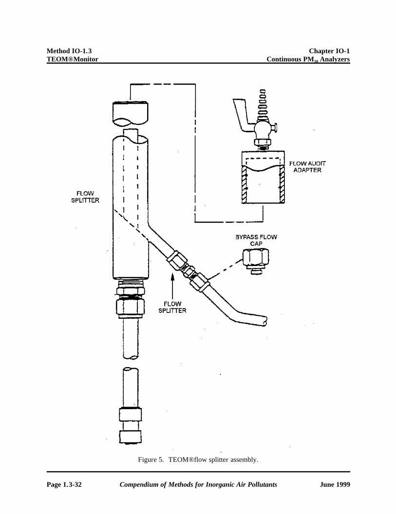
Method IO-1.3 Chapter IO-1 TEOM® Monitor Continuous PM10 Analyzers
Figure 5. TEOM® flow splitter assembly.
Page 1.3-32 Compendium of Methods for Inorganic Air Pollutants June 1999

Chapter IO-1 Method IO-1.3 Continuous PM10 Analyzers TEOM® Monitor
Figure 6. TEOM® filter cartridge assembly illustrating loading and removing filter.
June 1999 Compendium of Methods for Inorganic Air Pollutants Page 1.3-33

Method IO-1.3 Chapter IO-1 TEOM® Monitor Continuous PM10 Analyzers
Figure 7. Schematic diagram of the assembled TEOM® monitor.
Page 1.3-34 Compendium of Methods for Inorganic Air Pollutants June 1999

Chapter IO-1 Method IO-1.3 Continuous PM10 Analyzers TEOM® Monitor
Figure 8. Back panel of TEOM® monitor.
June 1999 Compendium of Methods for Inorganic Air Pollutants Page 1.3-35

Method IO-1.3 Chapter IO-1 TEOM® Monitor Continuous PM10 Analyzers
Figure 9. Location of shipping latch on back panel of the TEOM® monitor.
Page 1.3-36 Compendium of Methods for Inorganic Air Pollutants June 1999
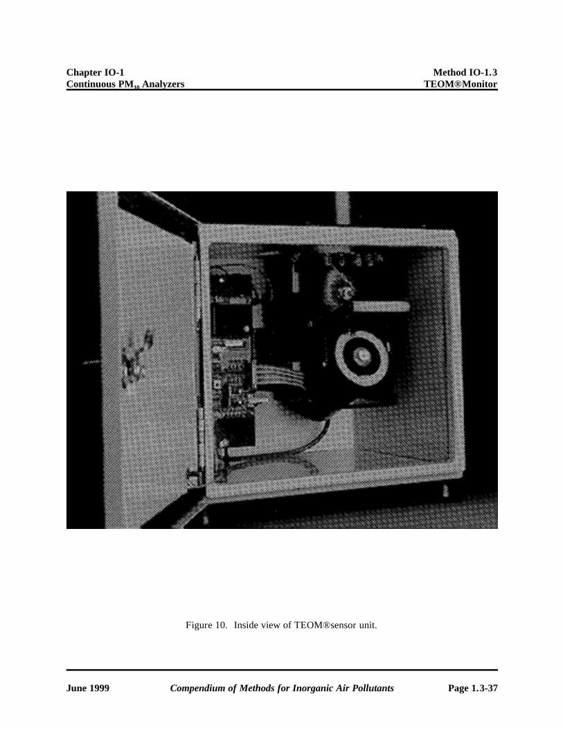
Chapter IO-1 Method IO-1.3 Continuous PM10 Analyzers TEOM® Monitor
Figure 10. Inside view of TEOM® sensor unit.
June 1999 Compendium of Methods for Inorganic Air Pollutants Page 1.3-37

Method IO-1.3 Chapter IO-1 TEOM® Monitor Continuous PM10 Analyzers
Figure 11. Schematic of typical TEOM® PM10 installation with flow splitter.
Page 1.3-38 Compendium of Methods for Inorganic Air Pollutants June 1999

Chapter IO-1 Method IO-1.3 Continuous PM10 Analyzers TEOM® Monitor
Figure 12. Replacing filter cartridge in sensor unit using filter exchange tool.
June 1999 Compendium of Methods for Inorganic Air Pollutants Page 1.3-39

Method IO-1.3 Chapter IO-1 TEOM® Monitor Continuous PM10 Analyzers
MAIN SCREEN (Screen 00)
Screen on Instrument
Description of Screen
Units Edit in Modes Default Re-Init Comments
OK 4 38% NU 09:39 6 N/A N/A N/A N/A Status Line
Mass Conc> 76.4 6 µg/m3 not editable N/A N/A Short-term average
30-Min MC 72.3 6 µg/m3 not editable N/A N/A Updated every 30 min
01-Hr MC 78.4 6 µg/m3 not editable N/A N/A Updated every 1 hr
08-Hr MC 85.8 6 µg/m3 not editable N/A N/A Updated every 1 hr
24-Hr MC 69.3 6 µg/m3 not editable N/A N/A Updated every 1 hr
Tot Mass 974.38 6 µg not editable N/A N/A Mass since last reset
Case Temp 50.00 6 EC not editable 50 50 Current temperature
Air Temp 50.01 6 EC not editable 50 50 Current temperature
Cap Temp 49.98 6 EC not editable 50 50 Current temperature
Encl Temp 40.00 6 EC not editable 40 40 Current temperature
Main Flow 3.00 6 l/min not editable 3 3 Current flow rate
Aux Flow 13.66 6 l/min not editable 13.67 13.67 Current flow rate
---------- 6 N/A N/A N/A N/A
Noise 0.034 6 µg not editable N/A N/A Diagnostic measure
Frequency 187.05738 6 hz not editable N/A N/A Mass transducer
To enter this screen press: <Main/Status> or 00 <Enter>
Next screen (using <Step Screen>): Menu Screen (Screen 02)
Figure 13. TEOM® main menu screens.
Page 1.3-40 Compendium of Methods for Inorganic Air Pollutants June 1999

Chapter IO-1 Method IO-1.3 Continuous PM10 Analyzers TEOM® Monitor
Figure 14. Auditing of the TEOM® flow control system.
June 1999 Compendium of Methods for Inorganic Air Pollutants Page 1.3-41

TABLE 5. EXAMPLE OF RECOMMENDED STANDARDS AND ASSOCIATED EQUIPMENT FOR FLOW RATE AUDITS
Transfer standarda Optimum flow range Qa Equipment Comments Calibration equationb,c Calibration of transfer standard reference
LFE (laminar flow element)
15.0-20.0 L/min LFE Thermometer/barometerd
Manometere, Filters, Adapter
Should have filtered air entering LFE. Subject to fluctuations due to temperature changes. Manometer must be used in its temperature range. Must equilibrate.
(ªH2O)(CF) = Qstd U. S. Environmental Protection Agency Procedures for Calibrating a Laminar Flow Element (LFE) against an NBS Calibrated LFE: Standard Operating Procedures EMSL/RTP SOP-QAD-003, November 1991
MFM (mass flow meter)
15.0-20.0 L/min MFM Thermometer/barometerd
Filters, Adapter
Recommended LCD display for outdoor use. Must equilibrate to ambient conditions.
(Volts)(CF) = Qstd Quality Assurance Handbook for Air Pollution Measurement Systems - Vol. II Ambient Air Specific Methods, Section 21, EPA 600/4-77-027A, May 1977.
DGM L/rev (dry gas meter)
15.0-20.0 L/min DGM Thermometer/barometerd
Stopwatch,f Filters, Adapter
Should time through five revolutions. Repeat each timing 3 times. Volume (CF) ' Qstdtime
Quality Assurance Handbook for Air Pollution Measurement Systems - Vol. II Ambient Air Specific Methods, Section 3.3 EPA 600/4-77-027B, August 1977.
Orifice 15.0-20.0 L/min Orifice Thermometer/barometer,d
Manometer,e Filters, Adapter
Good only in range ªP <8 in. 1/2 P am )H2O % b ' QstdTa
Quality Assurance Handbook for Air Pollution Measurement Systems - Vol. II Ambient Air Specific Methods, Section 2.2 EPA 600/4-77-027A. May 1977.
aTransfer standard should not cause more than 4.0" of H2O flow resistance to the sampler flow. bTraceable and referenced to EPA standard conditions:
Ta PstdQ ' a Qstd Pa Tstd
cCalibration equations for determining flow rates may vary from those presented due to the transfer standard calibration relationship. CF = correction factor. dThermometer capable of measuring temperature to the nearest +1C. Barometer capable of accurately measuring barometric pressure to the nearest +1 mm Hg. eThe design or size of the LFE or orifice will determine the manometer range necessary and the resolution. The manometer resolution must be capable of detecting a flow change of 1% and represent a flow resistance less than 4.0" H2O.
fStopwatch or timer capable of accurately measuring time intervals of 30 s to several minutes to nearest 0.1 s.