Metall-Special Melt treatment of Copper - „Ways to a high ... · refining of secondary copper...
7
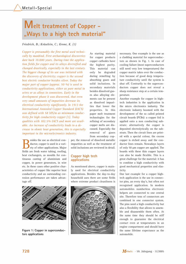
· 59. Jahrgang · 11/2005 728 Metall-Special As starting material for copper products copper cathodes have the highest purity. This material can only be degraded during remelting by absorbing gases and solid inclusions. In secondary materials besides dissolved gas- es also alloying ele- ments can be present as dissolved impuri- ties that lower the properties. In this paper melt treatment technologies for the refining of secondary copper melts are dis- cussed. Especially the removal of gases from secondary cop- per, the removal of dissolved metallic impurities as well as the treatment of solid inclusions are reviewed in detail. Copper high tech applications As mentioned above, copper is main- ly used for electrical conductivity applications. Besides the day-to-day household uses there are some fields where extreme product cleanliness is B esides the use as electrical con- ductor, copper is used in a vari- ety of other applications. Major fields are fresh water tubing, roofing, heat exchangers, as moulds for con- tinuous casting of aluminium and copper, in power generators, in wire etc. In these cases other positive char- acteristics of copper like superior heat conductivity and an outstanding cor- rosion performance are taken advan- tage off. necessary. One example is the use as a cladding material for superconduc- tors as shown in Fig. 1. In case of cooling failure (most superconductors still need very low temperatures) the copper matrix takes over the conduc- tion because of good deep tempera- ture conductivity until the system is shut off. Contrarily to the supercon- ductors copper does not reveal a sharp resistance step at a certain tem- perature. Another example for copper in high- tech industries is the application in the micro electronics industry. The electronic industry boomed with the development of the so called printed circuit boards (PCBs): a copper foil is applied onto a non conducting sub- strate; alternatively the copper is deposited electrolytically on the sub- strate. Then the circuit lines are print- ed with a special colour, the excess copper is etched away and the con- ductor lines remain. Nowadays layers of only 50 μm copper are applied. The boards with these thin copper layers can also be made flexible. This is a great challenge for the material: it has to combine a high conductivity with good mechanical properties and elas- ticity. One last example for a copper high- tech application is the use in connec- tor pins, an every day’s, but often not recognised application. In modern automobiles numberless electronic helpers are connected to one central site. Therefore tens of connectors are combined in one connector system. The pins need a high conductivity but also a flexibility that allows to assem- ble and disassemble them often. At the same time they should be stiff enough to guarantee the electrical contact even at temperatures in an engine compartment and should have the same lifetime expectance as the automobile. Melt treatment of Copper - „Ways to a high tech material“ Friedrich, B.; Kräutlein, C.; Krone, K. (1) Copper is presumably the first metal used techni- cally by mankind. First archaeological discoveries date back 10.000 years. During time the applica- tion fields for copper and its alloys diversified and changed drastically, especially in the last century. The biggest change of its use was initiated with the discovery of electricity; copper is the second best electric conductor besides silver. Today the major part of copper (approx. 50 %) is used in conductivity applications, either as pure metal in wires or as alloys in connectors. Early in the development phase it was discovered, that even very small amounts of impurities decrease its electrical conductivity significantly. In 1913 the International Annealed Copper Standard (IACS) was defined with 58 MS/m as minimum conduc- tivity for high conductivity copper [1]. Today qualities with 102.5% IACS and more are avail- able. An increase of conductivity leads to a de- crease in ohmic heat generation, this is especially important in the microelectronics industry. Figure 1: Copper in superconduc- tors applications
Transcript of Metall-Special Melt treatment of Copper - „Ways to a high ... · refining of secondary copper...
· 59. Jahrgang · 11/2005728
Metal l-Specia l
As starting materialfor copper productscopper cathodes havethe highest purity.This material canonly be degradedduring remelting byabsorbing gases andsolid inclusions. Insecondary materialsbesides dissolved gas-es also alloying ele-ments can be presentas dissolved impuri-ties that lower theproperties. In thispaper melt treatmenttechnologies for therefining of secondarycopper melts are dis-cussed. Especially theremoval of gasesfrom secondary cop-
per, the removal of dissolved metallicimpurities as well as the treatment ofsolid inclusions are reviewed in detail.
Copper high tech applications
As mentioned above, copper is main-ly used for electrical conductivityapplications. Besides the day-to-dayhousehold uses there are some fieldswhere extreme product cleanliness is
Besides the use as electrical con-ductor, copper is used in a vari-ety of other applications. Major
fields are fresh water tubing, roofing,heat exchangers, as moulds for con-tinuous casting of aluminium andcopper, in power generators, in wireetc. In these cases other positive char-acteristics of copper like superior heatconductivity and an outstanding cor-rosion performance are taken advan-tage off.
necessary. One example is the use asa cladding material for superconduc-tors as shown in Fig. 1. In case ofcooling failure (most superconductorsstill need very low temperatures) thecopper matrix takes over the conduc-tion because of good deep tempera-ture conductivity until the system isshut off. Contrarily to the supercon-ductors copper does not reveal asharp resistance step at a certain tem-perature.Another example for copper in high-tech industries is the application inthe micro electronics industry. Theelectronic industry boomed with thedevelopment of the so called printedcircuit boards (PCBs): a copper foil isapplied onto a non conducting sub-strate; alternatively the copper isdeposited electrolytically on the sub-strate. Then the circuit lines are print-ed with a special colour, the excesscopper is etched away and the con-ductor lines remain. Nowadays layersof only 50 µm copper are applied. Theboards with these thin copper layerscan also be made flexible. This is agreat challenge for the material: it hasto combine a high conductivity withgood mechanical properties and elas-ticity.One last example for a copper high-tech application is the use in connec-tor pins, an every day’s, but often notrecognised application. In modernautomobiles numberless electronichelpers are connected to one centralsite. Therefore tens of connectors arecombined in one connector system.The pins need a high conductivity butalso a flexibility that allows to assem-ble and disassemble them often. Atthe same time they should be stiffenough to guarantee the electricalcontact even at temperatures in anengine compartment and should havethe same lifetime expectance as theautomobile.
Melt treatment of Copper -„Ways to a high tech material“
Friedrich, B.; Kräutlein, C.; Krone, K. (1)
Copper is presumably the first metal used techni-cally by mankind. First archaeological discoveriesdate back 10.000 years. During time the applica-tion fields for copper and its alloys diversified andchanged drastically, especially in the last century.The biggest change of its use was initiated withthe discovery of electricity; copper is the secondbest electric conductor besides silver. Today themajor part of copper (approx. 50 %) is used inconductivity applications, either as pure metal inwires or as alloys in connectors. Early in thedevelopment phase it was discovered, that evenvery small amounts of impurities decrease itselectrical conductivity significantly. In 1913 theInternational Annealed Copper Standard (IACS)was defined with 58 MS/m as minimum conduc-tivity for high conductivity copper [1]. Todayqualities with 102.5% IACS and more are avail-able. An increase of conductivity leads to a de-crease in ohmic heat generation, this is especiallyimportant in the microelectronics industry.
Figure 1: Copper in superconduc-tors applications
These three fields of application are, ofcourse, only a very small extract ofthe copper world. Copper and itsalloys are also used in vacuum switch-es, vacuum capacitors, electron beamtubes, welding electrodes, heatexchangers, as moulds for continuouscasting of steel, aluminium and cop-per, in generators of power plants andwire and so on.
Processing of liquid Copper
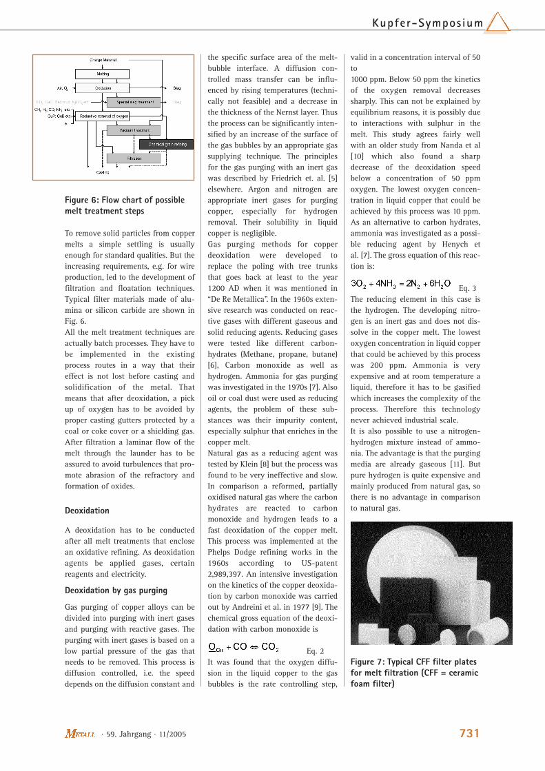
The processing of primary copper usu-ally starts with the melting of coppercathodes in a shaft furnace. For melt-ing of copper scrap in general induc-tion furnaces or drum furnaces areapplied. After the preliminary meltingfurnace the melt is either casteddirectly or subjected to a casting fur-nace where the melt is stored, (alloyed)and heated to casting temperature. Forcopper the continuous wire casting bycasting wheels or Hazelett casters isespecially important. Besides wirecasting also vertical and horizontalslab casting is applied as well asmould casting etc.
Impurities in copper melts
The issue of impurities in copper canbe separated in two parts: impuritiesin primary copper remaining or col-
lected after refining electrolysis andimpurities in secondary not electro-refined copper scrap. The refiningelectrolysis produces cathodes withmin. 99.995 wt. % Cu, the majorremaining impurities are silver, sul-phur, nickel and iron. But the contentsare usually so small that they are notdetrimental to the properties of cop-per. The more critical elements in thissense namely hydrogen and oxygen aswell as inclusions enter the primarycopper usually during the remeltingand casting process.In secondary materials the impuritymatter is more complicated. Remeltingof copper scrap makes sense ecologi-cally and economically because thematerial does not have to be lead backinto the energy intensive primaryelectrolysis. There are two types ofscrap, the sorted and mostly cleanproduction scrap which is easily anddirectly reusable and end of lifecyclescrap (=”old scrap”) consisting oftenof a mixture of different alloys or evencompounds with other metals andmaterials. In the process of producinga clean and specified alloy the unde-sired elements either have to beremoved or diluted. In case they arenot removed they can e.g. form inter-metallic phases in the copper matrixand as a result decrease the mechani-cal properties like the ultimate yieldstrength and the ductility. Due to thenoble character of copper, most ele-ments like silicon, aluminium and ironcan easily be removed from a copper
melt by selective oxidation up to avery low concentration (activity).Physically and chemically more simi-lar elements like nickel, cobalt, tin andlead have to be treated with moreattention. Elements and compoundstypically occurring in copper melts aresummarised in Fig. 4. Dissolved metal-lic impurities in small amounts mostlyare not detrimental to the properties ofcopper, but some elements as forexample Lead and Arsenic precipitateat the grain boundaries of the coppermaterials and lead to embrittlement ofthe material.Generally an oxygen and hydrogenpick-up can lead to very negativeeffects. The two gases have a high sol-ubility in liquid copper that decreasessharply during solidification. This canlead to a bubble formation, i.e. poros-ity in the solid material. Oxygen canalso form cuprous oxide (Cu2O) aboveits solubility level that immediatelyreacts with the hydrogen of anannealing or welding atmosphereforming water vapour during anneal-ing or welding, this phenomenon iscalled hydrogen embrittlement. Dis-solved hydrogen and oxygen (or Cu2O)will react to water under extreme pres-sure in the lattice and will form cracksand lead to embrittlement.Solid inclusions like intermetallics oroxides from alloying elements or therefractory material usually do nothave a negative impact on copper andcopper alloys. Because the density dif-ference between the copper melt and
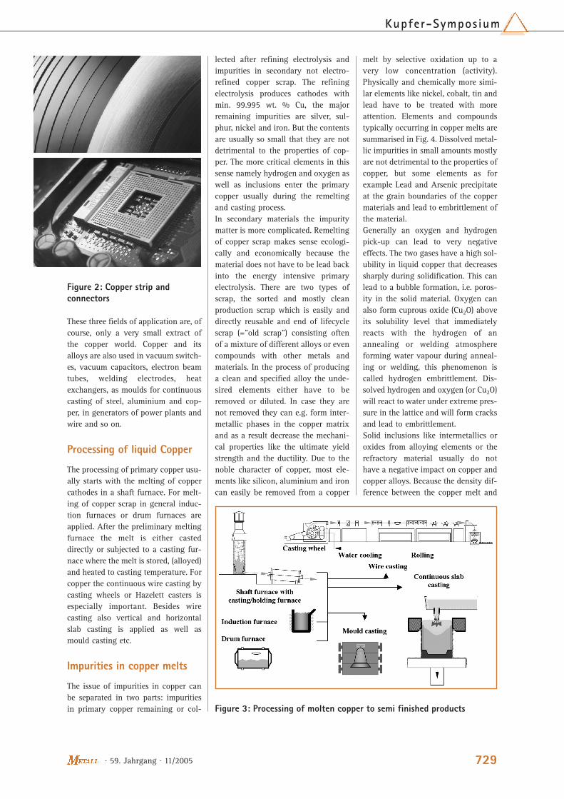
Figure 2: Copper strip andconnectors
Figure 3: Processing of molten copper to semi finished products
729
Kupfer-Symposium
· 59. Jahrgang · 11/2005

· 59. Jahrgang · 11/2005730
Metal l-Specia l
the particles is very high the particlestend to float to the surface (e.g. thedensity of copper at 1100 °C is 7.96g/cm3 while Iron oxide has a densityof 5.25 g/cm3 [2]). However Stokes lawpredicts that even at high density dif-ferences very small particles tend tostay suspended (In case of FeO parti-cles the diameter smaller than 10 µmrise with 0.59 m/h). This leads to prob-lems where wires with a very smalldiameter are drawn, for thin copperfoils or where small connector pins aremade from thin copper strip, beingetched or punched.
Requirements for clean cop-per melts
The most frequent impurity in refinedcopper is oxygen. If the alloy is notmolten under oxygen free atmosphere,copper melts will always pick up Oxy-gen. Copper melts hyper saturatedwith oxygen lead holes or the so calledhydrogen embrittlement during cast-ing and welding in case hydrogen ispresent in the material or the atmos-phere. Dissolved oxygen can also oxi-dise less noble elements which leads tothe formation of brittle oxides in thematerial. In technically alloys, an oxy-gen content of a few hundred ppm isaccepted whereas in special gradematerials the content has to be low-ered below one ppm, some grades andtheir respective tolerated oxygen con-tent are summarised in the following:
E-Cu > 99.9 wt. % Cu90 - 400 ppm OCu
OF-Cu > 99.99 wt. % Cu0.9 - 5 ppm OCu
SE-Cu > 99.9 wt. Cu (30 ppm P)0.2 – 1 ppm OCu
In technical alloys the limit for speci-fied metallic impurities mainly varies
between 0.03 wt. % and 0.05 wt. %. Atypical requirement for DHP-Cu is forexample all elements except for phos-phorous <0.05 wt. %, specified ele-ments (Fe, Ni, Zn) max. 150 ppm allremaining elements max 50 ppm [3].For high quality products limits of < 90 ppm Pb, < 50 ppm Sn and < 150ppm Ni are required.Solid inclusions are especially a prob-lem in thin wire drawing and thinsheets rolling. Eq. 1 describes the crit-ical inclusion size, any particle biggerwill initiate wire breaks:
Eq. 1
with dcritical: inclusion size that leadsto a break, D: wire diameter, K is amaterial constant, T: applied pullingtension, n: reduction ratio.That means that the possibility for awire break increases sharply with thesize reduction ratio and the pullingtension. In foil production inclusionslead to a foil break in the worst case.Smaller inclusions lead to surfacedefects and elongated holes in thematerial.
Refining by melt treatment
The mentioned impurities can bereduced to an uncritical content by anappropriate melt treatment beforecasting. Different melt treatment tech-nologies of copper were developed fordifferent impurities. The “classical”melt treatment of copper is the oxida-tion by air or oxygen injection or topblowing. With this technique elementsthat are less noble than copper can beremoved from the melt. Today thistechnique is often combined with aspecific slag that can take up the
impurity oxides and supplies a certainoxygen potential to improve theimpurity separation.To remove dissolved gases especiallyhydrogen and oxygen the oldestmethod is first of all the right melthandling. That means that the openmelt surface has to be shielded andmelt transfer has to be in a laminarflow in order to inhibit turbulences.Hydrogen can be removed by anexcess of oxygen in the melt. After theremoval of hydrogen by oxidisingconditions, the melt has to be treatedunder reducing conditions to removethe oxygen. A new pick-up of hydro-gen has to be avoided by shielding ofthe melt with slags, coal layers orshielding gases. oxygen is usuallyadded by blowing air on the melt sur-face. For the reduction since formertimes the so called poling by treetrunks, especially birch, is used [4].This technique is still used today insome places. An advantage of the treetrunks is that they have a CO2 emis-sion of zero, as plants are consideredto be regenerative. Alternatively tothis classical procedure, modern tech-niques reduce the partial pressure inthe surrounding atmosphere; this ledto vacuum and gas purging technolo-gies. A flow chart of possible melttreatment routs is shown in Fig. 5.The removal of dissolved metals incopper is an upcoming problembecause of the increasing recyclingmaterial volume not being treated byrefining electrolysis. Metals like zinc,arsenic and antimony can be evapo-rated by a vacuum treatment, for oth-ers like nickel, cobalt, tin and lead aspecial slag treatment is more eco-nomic. Nevertheless very often thehigh specifications of high tech appli-cations cannot be met using only onerefining technique.
Figure 4: Impurities in copper melts
Figure 5: Requirements for oxy-gen contents in copper
To remove solid particles from coppermelts a simple settling is usuallyenough for standard qualities. But theincreasing requirements, e.g. for wireproduction, led to the development offiltration and floatation techniques.Typical filter materials made of alu-mina or silicon carbide are shown inFig. 6.All the melt treatment techniques areactually batch processes. They have tobe implemented in the existingprocess routes in a way that theireffect is not lost before casting andsolidification of the metal. Thatmeans that after deoxidation, a pickup of oxygen has to be avoided byproper casting gutters protected by acoal or coke cover or a shielding gas.After filtration a laminar flow of themelt through the launder has to beassured to avoid turbulences that pro-mote abrasion of the refractory andformation of oxides.
Deoxidation
A deoxidation has to be conductedafter all melt treatments that enclosean oxidative refining. As deoxidationagents be applied gases, certainreagents and electricity.
Deoxidation by gas purging
Gas purging of copper alloys can bedivided into purging with inert gasesand purging with reactive gases. Thepurging with inert gases is based on alow partial pressure of the gas thatneeds to be removed. This process isdiffusion controlled, i.e. the speeddepends on the diffusion constant and
the specific surface area of the melt-bubble interface. A diffusion con-trolled mass transfer can be influ-enced by rising temperatures (techni-cally not feasible) and a decrease inthe thickness of the Nernst layer. Thusthe process can be significantly inten-sified by an increase of the surface ofthe gas bubbles by an appropriate gassupplying technique. The principlesfor the gas purging with an inert gaswas described by Friedrich et. al. [5]elsewhere. Argon and nitrogen areappropriate inert gases for purgingcopper, especially for hydrogenremoval. Their solubility in liquidcopper is negligible.Gas purging methods for copperdeoxidation were developed toreplace the poling with tree trunksthat goes back at least to the year1200 AD when it was mentioned in“De Re Metallica”. In the 1960s exten-sive research was conducted on reac-tive gases with different gaseous andsolid reducing agents. Reducing gaseswere tested like different carbon-hydrates (Methane, propane, butane)[6], Carbon monoxide as well ashydrogen. Ammonia for gas purgingwas investigated in the 1970s [7]. Alsooil or coal dust were used as reducingagents, the problem of these sub-stances was their impurity content,especially sulphur that enriches in thecopper melt.Natural gas as a reducing agent wastested by Klein [8] but the process wasfound to be very ineffective and slow.In comparison a reformed, partiallyoxidised natural gas where the carbonhydrates are reacted to carbonmonoxide and hydrogen leads to afast deoxidation of the copper melt.This process was implemented at thePhelps Dodge refining works in the1960s according to US-patent2,989,397. An intensive investigationon the kinetics of the copper deoxida-tion by carbon monoxide was carriedout by Andreini et al. in 1977 [9]. Thechemical gross equation of the deoxi-dation with carbon monoxide is
Eq. 2It was found that the oxygen diffu-sion in the liquid copper to the gasbubbles is the rate controlling step,
valid in a concentration interval of 50to 1000 ppm. Below 50 ppm the kineticsof the oxygen removal decreasessharply. This can not be explained byequilibrium reasons, it is possibly dueto interactions with sulphur in themelt. This study agrees fairly wellwith an older study from Nanda et al[10] which also found a sharpdecrease of the deoxidation speedbelow a concentration of 50 ppmoxygen. The lowest oxygen concen-tration in liquid copper that could beachieved by this process was 10 ppm.As an alternative to carbon hydrates,ammonia was investigated as a possi-ble reducing agent by Henych etal. [7]. The gross equation of this reac-tion is:
Eq. 3The reducing element in this case isthe hydrogen. The developing nitro-gen is an inert gas and does not dis-solve in the copper melt. The lowestoxygen concentration in liquid copperthat could be achieved by this processwas 200 ppm. Ammonia is veryexpensive and at room temperature aliquid, therefore it has to be gasifiedwhich increases the complexity of theprocess. Therefore this technologynever achieved industrial scale.It is also possible to use a nitrogen-hydrogen mixture instead of ammo-nia. The advantage is that the purgingmedia are already gaseous [11]. Butpure hydrogen is quite expensive andmainly produced from natural gas, sothere is no advantage in comparisonto natural gas.
Figure 6: Flow chart of possiblemelt treatment steps
Figure 7: Typical CFF filter platesfor melt filtration (CFF = ceramicfoam filter)
731
Kupfer-Symposium
· 59. Jahrgang · 11/2005
· 59. Jahrgang · 11/2005732
Metal l-Specia l
Up till now the favoured gas injectiontechnology in the copper industry istuyeres/injectors even though in otherindustries different gas supplyingtechniques are used as rotary vaneddispersers and porous plugs.
Deoxidation by addition of solidadditives
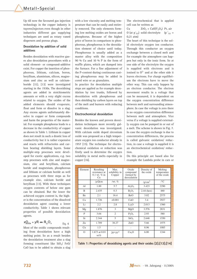
Besides deoxidation with reactive gas-es also deoxidation procedures with asolid element- or compound-additiveexist. For copper the insertion of phos-phorous, lithium, calcium, boron,beryllium, aluminium, silicon, magne-sium and zinc as well as calcium-boride [11]; [13] were investigatedstarting in the 1930s. The deoxidisingagents are added in stoichiometricamounts or with a very slight excessrelated to oxygen. The oxides of theadded elements should evaporate,float and form or dissolve in a slag.Any excess agents unfortunately dis-solve in copper or form compoundsand harm the properties of the mater-ial. For example phosphorus leads to adecrease in the conductivity of copperas shown in Table 1. Lithium in copperdoes not result in such a drastic loss ofconductivity but it is rather expensiveand reacts with refractories and car-bon bearing shielding layers. Somemultiple-step processes were devel-oped for exotic applications, e.g. twostep processes with zinc and magne-sium, zinc and beryllium, calciumboride and magnesium, phosphorousand lithium or calcium boride as wellas processes with three steps as forexample zinc, calcium boride andberyllium [13]. With these techniquesoxygen contents of below one ppmcan be obtained. But the lower theachieved oxygen content is, the high-er is the concentration of the dissolveddeoxidation agent causing a lowerconductivity. Table 1 shows relevantproperties of possible deoxidationagents.
Eq. 4Most of the oxidic compounds result-ing from deoxidation have a highmelting point. So as a result besidesthe deoxidation treatment also a slagforming constituent like SiO2/ FeO/CaO has to be added to obtain a slag
with a low viscosity and melting tem-perature that can be easily and entire-ly removed. The only elements form-ing low melting oxides are boron andphosphorus. Because of the higherprice of boron in comparison to phos-phorous, phosphorous is the deoxida-tion element of choice until today.Phosphorous is usually added as amaster alloy with the composition 90 % Cu and 10 % P in the form ofwaffle plates, which are dumped intothe furnace. For a fine adjustment ofthe P-content during continuous cast-ing phosphorous may be added incored wire or as granulates.In practice for deoxidation multiplesteps are applied as for example deox-idation by tree trunks, followed bydeoxidation with phosphorous andthen shielding by carbon layers on topof the melt and burners with reducingconditions.
Electrochemical deoxidation
Besides the known and proven deoxi-dation techniques more recently gal-vanic deoxidation was investigated.With calcium oxide doped zirconiumoxide was proposed as a high temper-ature oxygen ion conductor already in1957 [15]. The technique for electro-chemical oxidation or reduction wasfirstly used to determine the oxygensolubility in metal melts especially incopper [16].
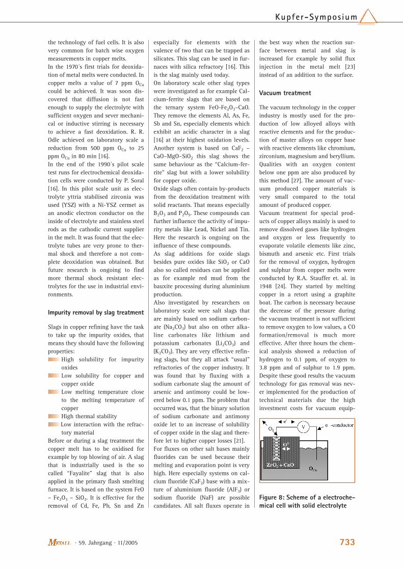
The electrochemical that is appliedcell can be written as Cu ZrO2 + CaO(Y2O3) Pt, airO (at p´O2) solid electrolyte (p´´O2 =0,21 atm)The heart of this technique is the sol-id electrolyte oxygen ion conductor.Through this conductor an oxygenexchange between a closed melt andfor example the atmosphere can hap-pen but only in the ionic form. So atone side of the electrolyte the oxygenis supplied with electrons and isionised to O2- and at the other side itleaves electrons. For charge equilibri-um the electrons have to move theother way. This can only happen byan electron conductor. The electronmovement results in a voltage thatcan be measured, it is dependent onthe oxygen concentration differencebetween melt and surrounding atmos-phere. In case the voltage is zero thereis no oxygen concentration differencebetween melt and atmosphere. Viceversa if a voltage is supplied external-ly oxygen can be pumped in or out ofa melt. The scheme is shown in Fig. 7.In case the oxygen exchange is due toconcentration differences, the processis called galvanic oxidation/ reduc-tion, in case a voltage is supplied it isan electrochemical oxidation/ reduc-tion.On this principle are based also forexample the Lambda probe in cars or
Table 1: Properties of deoxidising agents and their oxides [2];[13];[14]
Element Resultingresistance at0.1 wt. % in
Cu
Max.solubility in
Copper
Oxidecompoundformed by
deoxidation
Density ofthe oxide
Meltingtemperatureof the oxide
/µΩcm /wt. % /g/cm3 /°C
Al 1.89 5.7 Al2O3 3.423 2290
B 2.435 0.3 B2O3 2.44 (hex) 460
Be 2.1 16.4 BeO 3.02 2575
Ca 1.726 <0.001 CaO 3.4 2927
Li 2.2 2.8 Li2O 2.013 1560
Mg 1.876 3 MgO 3.576 2831
P 3.04 2 P2O5 2.93 580
Si 2.344 5 SiO2 2.648 1550
Zn 1.709 38.27 ZnO 5.66 1975
Cu 1.5 - - 8.96 1085
O 1.673 at 0.01wt%
20*10-4 Cu2O 6.00 1244
the technology of fuel cells. It is alsovery common for batch wise oxygenmeasurements in copper melts.In the 1970´s first trials for deoxida-tion of metal melts were conducted. Incopper melts a value of 7 ppm OCu
could be achieved. It was soon dis-covered that diffusion is not fastenough to supply the electrolyte withsufficient oxygen and sever mechani-cal or inductive stirring is necessaryto achieve a fast deoxidation. R. R.Odle achieved on laboratory scale areduction from 500 ppm OCu to 25ppm OCu in 80 min [16].In the end of the 1990´s pilot scaletest runs for electrochemical deoxida-tion cells were conducted by P. Soral[16]. In this pilot scale unit as elec-trolyte yttria stabilised zirconia wasused (YSZ) with a Ni-YSZ cermet asan anodic electron conductor on theinside of electrolyte and stainless steelrods as the cathodic current supplierin the melt. It was found that the elec-trolyte tubes are very prone to ther-mal shock and therefore a not com-plete deoxidation was obtained. Butfuture research is ongoing to findmore thermal shock resistant elec-trolytes for the use in industrial envi-ronments.
Impurity removal by slag treatment
Slags in copper refining have the taskto take up the impurity oxides, thatmeans they should have the followingproperties:
High solubility for impurityoxidesLow solubility for copper andcopper oxideLow melting temperature closeto the melting temperature ofcopperHigh thermal stabilityLow interaction with the refrac-tory material
Before or during a slag treatment thecopper melt has to be oxidised forexample by top blowing of air. A slagthat is industrially used is the socalled “Fayalite” slag that is alsoapplied in the primary flash smeltingfurnace. It is based on the system FeO– Fe2O3 – SiO2. It is effective for theremoval of Cd, Fe, Pb, Sn and Zn
especially for elements with thevalence of two that can be trapped assilicates. This slag can be used in fur-naces with silica refractory [16]. Thisis the slag mainly used today.On laboratory scale other slag typeswere investigated as for example Cal-cium-ferrite slags that are based onthe ternary system FeO-Fe2O3–CaO.They remove the elements Al, As, Fe,Sb and Sn, especially elements whichexhibit an acidic character in a slag[16] at their highest oxidation levels.Another system is based on CaF2 –CaO–MgO–SiO2 this slag shows thesame behaviour as the “Calcium-fer-rite” slag but with a lower solubilityfor copper oxide.Oxide slags often contain by-productsfrom the deoxidation treatment withsolid reactants. That means especiallyB2O3 and P2O5. These compounds canfurther influence the activity of impu-rity metals like Lead, Nickel and Tin.Here the research is ongoing on theinfluence of these compounds.As slag additions for oxide slagsbesides pure oxides like SiO2 or CaOalso so called residues can be appliedas for example red mud from thebauxite processing during aluminiumproduction.Also investigated by researchers onlaboratory scale were salt slags thatare mainly based on sodium carbon-ate (Na2CO3) but also on other alka-line carbonates like lithium andpotassium carbonates (Li2CO3) and(K2CO3). They are very effective refin-ing slags, but they all attack “usual”refractories of the copper industry. Itwas found that by fluxing with asodium carbonate slag the amount ofarsenic and antimony could be low-ered below 0.1 ppm. The problem thatoccurred was, that the binary solutionof sodium carbonate and antimonyoxide let to an increase of solubilityof copper oxide in the slag and there-fore let to higher copper losses [21]. For fluxes on other salt bases mainlyfluorides can be used because theirmelting and evaporation point is veryhigh. Here especially systems on cal-cium fluoride (CaF2) base with a mix-ture of aluminium fluoride (AlF3) orsodium fluoride (NaF) are possiblecandidates. All salt fluxes operate in
the best way when the reaction sur-face between metal and slag isincreased for example by solid fluxinjection in the metal melt [23]instead of an addition to the surface.
Vacuum treatment
The vacuum technology in the copperindustry is mostly used for the pro-duction of low alloyed alloys withreactive elements and for the produc-tion of master alloys on copper basewith reactive elements like chromium,zirconium, magnesium and beryllium.Qualities with an oxygen contentbelow one ppm are also produced bythis method [27]. The amount of vac-uum produced copper materials isvery small compared to the totalamount of produced copper.Vacuum treatment for special prod-ucts of copper alloys mainly is used toremove dissolved gases like hydrogenand oxygen or less frequently toevaporate volatile elements like zinc,bismuth and arsenic etc. First trialsfor the removal of oxygen, hydrogenand sulphur from copper melts wereconducted by R.A. Stauffer et. al. in1948 [24]. They started by meltingcopper in a retort using a graphiteboat. The carbon is necessary becausethe decrease of the pressure duringthe vacuum treatment is not sufficientto remove oxygen to low values, a COformation/removal is much moreeffective. After three hours the chem-ical analysis showed a reduction ofhydrogen to 0.1 ppm, of oxygen to3.8 ppm and of sulphur to 1.9 ppm.Despite these good results the vacuumtechnology for gas removal was nev-er implemented for the production oftechnical materials due the highinvestment costs for vacuum equip-
Figure 8: Scheme of a electroche-mical cell with solid electrolyte
733
Kupfer-Symposium
· 59. Jahrgang · 11/2005

· 59. Jahrgang · 11/2005734
Metal l-Specia l
ment and its maintenance. Only thecompany Hitachi patented a continu-ous process in 1989 that is in use untiltoday [21].In the 1970s the possibility to removeother elements than dissolved gasesby means of vacuum was investigat-ed. In the focus were mainly bismuth,antimony and arsenic because theyoften accompany the copper ores andare difficult to remove during therefining electrolysis. These elementshave a negative effect on the proper-ties of copper and its alloys, so theirremoval is of great importance [26].The removal of bismuth, lead, arsenicand antimony from copper [26] wasinvestigated and it was found that forcopper alloys the bismuth contentcould be reduced to 70 ppm, arsenicto 1260 ppm and antimony to 310ppm. The distillation of volatile ele-ments is not very common industrial-ly.For the removal of gases three differ-ent setups of furnaces can be used.Usually the heating source in vacuumfurnaces is an induction heating. Thevacuum induction melting (VIM) fur-nace consists of a cold walled cham-ber in which all equipment likemoulds etc. is stored. The inductioncoil can be tilted so that inside thematerial can be casted inside the fur-nace under vacuum. In the vacuuminduction degassing system (VID) a lidis positioned on the top of the fur-nace. Before casting the lid has to beremoved, and the melt is subjectedagain to the atmosphere. The advan-tage of this system is the small size incomparison to the VIM. The third sys-tem is the so called vacuum inductiondegassing pouring (VIDP). The coldwalled container of the induction coilcan be tilted so that the melt flows ina launder and leaves the cold walledsystem through a closed launderchamber. This system avoids the con-tact to the air during casting andcombines the advantages of VIM andVID.
Summary
In this paper the possibilities for themelt treatment of copper and copperalloy melts are discussed. Gas purg-
ing, deoxidation by chemical reac-tion, slag treatment and vacuumtreatment were reviewed in moredetail. The review shows that woodpoling can achieve oxygen contentsto a few hundred ppm, cracked natur-al gas can reduce the oxygen down toa few tens of a ppm and a deoxidationby solid reactants leads to below 1ppm of oxygen in a copper melt. Avacuum treatment can also reduce theoxygen level to ~ 1 ppm.With a melt treatment with a slag dis-solved metallic impurities can bereduced below critical values. Fayaliteslags that are the most common canremove elements with the valence oftwo as silicates as for example Pb, Cd,Sn and Fe. Carbonate slags canremove As and Sb below 1 ppm, butare not technically used.The results show that nearly all ele-ments can be removed from coppermelts in the molten state, avoidingthe energy intensive refining electrol-ysis. Because all melt treatment tech-nologies in the copper industry arebatch processes their implementationhas to undergo critical considerationto fit them into the existing processlines. Also the effect of the differenttreatment technologies has to bemaintained until the metal is castedand chilled. Therefore effectiveshielding measures by carbon layersand shielding gases have to be addedto the actual melt treatment process.
The state of the art of the existingmelt treatment process technologiesenables the copper industry to achievethe dire demands of the semi finishedproduct consumers.
References[1] G. Armstrong Smith; JIM, Vol. 100,
1972, pp. 125 – 130[2] R. Blachnik, D´Ans Lax; Springer Verlag
1998, ISBN 3-540-60035-3[3] CEN/TS 13388:2004[4] E. Brunhuber; 1959, Fachverlag Schiele
und Schön GmbH[5] B. Friedrich, K. Krone, C. Kräutlein;
METALL, Vol. 59, 2005, pp. 30 – 36[6] F.E. Brantley, C.H. Schack: Bureau of
mines R.I. 6113, 1962[7] R. Henych, F. Kadlec, V. Sedlacek; JOM,
1965, pp. 386 – 388[8] L. Klein; JOM, Aug. 1961, pp. 545 – 547[9] R. J. Andreini, J.S. Foster, R. B. Phillips;
Metall. Trans. B, Vol. 8B, 1977, pp. 633 –638
[10]C. R. Nanda, G. H. Geiger; Metall.Trans., Vol. 2, April 1971, pp. 1101 –1106
[11] K. Fasshauer, F. Steffner, H.-J. Dauerst-edt; EP 0992597B1, 2002
[12]Kh. G. Schmitt-Thomas, H. Meisel, H.-J. Dorn, H. Rasavisadeh; METALL, Vol.29, Heft 12, Dec. 1975, pp. 1198 – 1204
[13]E. Brunhuber; Giesserei, Jan. 1959, pp. 2– 8
[14]Predel, B.; in: Landolt-Börnstein - GroupIV; Vol. 5x, Springer-Verlag Heidelberg,ISSN 1616-9557
[15]K. Kiukolla, C. Wagner; J. Electrochem.Soc., 1957, pp. 308 - 316
[16]P. Soral, U. Pal, H. R: Larson, B.Schroeder; Metall. Mater. Trans. B,1999, pp. 307 - 321
[17]R. R: Odle, R. A. Rapp; Metall. Trans. B,1977, pp. 581 - 589
[18]D. Janke; Zeitschrift für Metallkunde,1977, pp. 302 - 307
[19] J. Gerlach, J. Osterwald, W. Stichel; Z.Metallkd., 1968, 576 - 582
[20] J. Gortais, F. Hodaj, M. Allibert, J.-M.Welter; Metall. Mater. Trans. B, Vol.25B, Oct. 1994, pp. 645 – 651
[21] Japanese Patent JP01142016A, 1989[22]H. Fukuyama, T. Fujisawa, C. Yamauchi;
Metallurgical Processes for the EarlyFirst Century, The Minerals, Metals &Materials Society 1994, pp. 443 – 452
[23]B. Zhao, N. J. Themelis; EPD Congress,The Minerals, Metals & Materials Soci-ety, 1995, pp. 515 – 524
[24]R. A. Stauffer, K. Fox, W. O. DiPietro;Ind. Eng. Chem., May 1948, pp. 820 –825
[25]O. Yutaka, O. Takeji, Japanese Patent01142016, 1989
[26]R. Harris; Metall. Trans. B; Vol. 15B,June 1984, pp. 251 – 257
[27]H. Rupp; Metall. Vol. 42, Heft 4, Apr.1988, pp. 356 - 363
(1) Prof. Dr.-Ing B. Friedrich, Dipl.-Ing. Christoph Kräutlein, Dr.-Ing.K. Krone †, RWTH Aachen
Figure 9: Vacuum furnace [27](VIM)