British Columbia Copper Smelting and Refining Technologies
256
ies Semi November 5 - 6 , 1980 Of „BCEMPR ]PAPER [1981-5 -MPR^Iumbia Sc. 2 MAI Ministry of Energy, Mines and Petroleum Resources PAPER 1981 -5 MINERAL ECONOMICS BRANCH MINERAL RESOURCES DIVISION
Transcript of British Columbia Copper Smelting and Refining Technologies
ies Semi
November 5 - 6 , 1980
Of „BCEMPR ]PAPER [1981-5 -MPR^Iumbia Sc. 2 MAI
Ministry of Energy, Mines and Petroleum Resources
PAPER 1981 -5
MINERAL ECONOMICS BRANCH MINERAL RESOURCES DIVISION
BRITISH COLUMBIA
MINISTRY OF
ENERGY, MINES AND PETROLEUM RESOURCES
BRITISH COLUMBIA POPPER SMELTING
AND
REFINING TECHNOLOGIES SEMINAR
NOVEMBER 5 - 6 , 1980 VANCOUVER, B.C.
EDITED BY: FRANK C. BASHAM
MINERAL ECONOMICS DIVISION January, 1981

Canadian Cataloguing in Publication Data
British Columbia Copper Smelting and Refining Technologies Seminar (1980 : Vancouver, B.C.) British Columbia Copper Smelting and Refining
Technologies Seminar, November 5-6, 1980, Vancouver, B.C.
(Paper, ISSN 0226-9^30 ; 1981-5)
Bibliography: p. ISBN 0-7718-830U-8
1. Copper - Metallury - Congresses. I. Basham, Frank C. II. British Columbia. Ministry of Energy, Mines and Petroleum Resources. III. Series: Paper (British Columbia. Ministry of Energy, Mines and Petroleum Resources) ; 1981-5.
TN780.B71* 669'.3 C82-092093-2

TABLE OF CONTENTS
SECTION Page
ACKNOWLEDGEMENTS 4
I INTRODUCTION By E.R. Macgregor and F.C. Basham 5
II INCO OXYGEN FLASH SMELTING OF COPPER CONCENTRATES By T.N. Antonioni, T.C. Burnett, and CM. Diaz 9
III THE NORANDA PROCESS By G.D. Hallett 49
IV RECENT OPERATION OF MITSUBISHI CONTINUOUS COPPER SMELTER AT NAOSHIMA By T. Suzuki 75
V THE OUTQKUMPU FLASH SMELTING METHOD By K. Murden and J. Sulanto 121
VI BANQUET SPEECH Address by the Hon. R.H. McClelland, Minister of Energy, Mines and Petroleum Resources 145
VII APPLICATION OF THE SHERRITT-COMINOO COPPER PROCESS TO BRITISH COLUMBIA COPPER CONCENTRATES By P. Kawulka and C.R. Kirby 157
VIII HIGH EFFICIENCY SYSTEM FOR PYROMETALLURGICAL RECOVERY OF HIGH-GRADE COPPER MATTE FROM SULFIDE CONCENTRATE By D.A. Mackie, P. Paschen, and G. Melcher 179
IX TCP BLOWN ROTARY CONVERTER (TBRCW) PROCESS FOR NON-FERROUS SMELTING, Q-S OXYGEN PROCESS, OKYGEN SPRINKLE PROCESS By R.A. Daniele 203
X OVERVIEW OF COPPER EXTRACTION TECHNOLOGY FOR BRITISH COLUMBIA By W.J.S. Craigen 219
APPENDIX ALPHABETICAL LIST OF REGISTRANTS - LIST OF SPEAKERS 245
3

ACKNOWLEDGEMENTS
This seminar and the present publication of proceedings could not have taken place without the magnificent effort and dedication of the authors, the commitment of the organizations they represent, and many staff within the B.C. Ministry of Energy, Mines and Petroleum Resources.
Josephine Harris, with the able assistance of Signy Thorleifson, handled a l l administrative aspects of the seminar. Carolyn Staith and Carmen Semturis of the Ministry's Mineral T i t l e s Division i n Vancouver, assisted us with registrations.
Ed Macgregor, Bruce MsRae, John Clancy, and B i l l Craigen provided considerable guidance in the formative stages of the seminar. As well, Bruce McRae acted as chairman for the second day of the session.
Finally, we would like to thank Pat Hrushowy, Terry Moran, and Richard Butler in our Ministry's Oomnunications Division, for assistance in publicity and printing; and B i l l MacMillan and Wes Johnson in the Geological Division for technical data supporting some of the author's presentations.
The Ministry i s grateful to a l l these individuals and organizations for supporting the seminar. The views expressed in these papers represent those of the authors, and may not necessarily reflect those of the organizations they represent.
F.C. Basham Director, Mineral Economics Division B.C. Ministry of Energy, Mines and Petroleum Resources Victoria, B.C.
4

SECTION 1
INTRODUCTION
BY E.R. MCGREGOR AND F.C. BASHAM
.C. Ministry of Energy, Mines and Petroleum Resources

The commissioning of Teck Corporation's Afton mine and smelter in the early 1970's represented the f i r s t contemporary smelting technology installed in the Province of British Columbia. Prior to this, smelting of copper ores had occurred at several locations in B.C., notably at Crofton and Ladysmith in the early 1900* s, and at Granby's Anyox mine in 1914. Hie older operations were closed in the 1930's.
Concurrent with the mineral commodities boom in the late 1960's and early 1970's, and associated with the opening up of large-scale surface mining for copper in porphyry deposits, several companies investigated the fe a s i b i l i t y of smelting copper in British Columbia. However, the prevailing economic circumstances were far more attractive for the mining and milling of copper concentrates than to carry on through the prime metal stage producing blister copper, anode or cathode. To some extent, these conditions s t i l l prevail today. Where B.C. concentrates are sold under contract, treatment and refining charges by the smelters are s t i l l reasonably attractive. The disposal of sulfuric acid, a by-product of pyrometallurgical processes for smelting sulfide copper concentrates, s t i l l poses a potential economic cost on smelting within B.C. due to the limited size of domestic markets for acid.
However, there are indications that some of these adverse circumstances are changing. As smelter capacity in Japan and the U.S. reaches f u l l u tilization, the economics of new greenfields smelter operations are tending to favour locations closer to the sources of concentrate in supply regions.
This seminar focuses on pyrometal lurgical and hydrometal lurgical technologies for the extraction of copper that might be applicable to Br i t i s h Columbia ores and concentrates. We asked the authors to address the subject from the viewpoint of process description, energy u t i l i z a tion, environmental features and economics. With this perspective, we hoped that mining companies and other agencies represented in our seminar audience would increase their awareness of the major features of contemporary smelting technology.
For reasons of time, we had to restrict the presentations to those technologies presently available and marketable on a commercial basis. Many other technologies are being developed and are approaching
6

commercial availability. We are hopeful that over the next few years, as parties seriously interested in smelting copper in British Columbia begin investigations, and as the Province's many advantages as a site for further processing become better understood, the whole range of appropriate technologies w i l l be examined.
7

SECTION II
INCO OXYGEN FLASH SMELTING OF COPPER CONCENTRATES
BY: T.N. ANTONIONI T.C. BURNETT CM. DIAZ H.C GARVEN

INOO OXYGEN FLASH SMELTING OF COPPER CONCENTRATE
BY:
T. N. Antonioni, Superintendent, Furnace Dept., Copper C l i f f
Dr T. C. Burnett, Manager, Process Sales, Toronto
Dr. C. M. Diaz, Section Head - Pyrometallurgy, Toronto
H. C. Garven, Process Manager, Toronto, INOO Metals Company
J. Roy Gordon Research Laboratory, Sheridan Park
Paper presented at the British Columbia Copper Smelting and Refining Technologies Seminar
November 5, 1980 Vancouver, B.C.
10
ABSTRACT
INCO Metals Company has operated an Oxygen Flash Smelting Process at i t s Copper C l i f f , Ontario, Smelter for almost 30 years. This paper describes the existing operations with particular emphasis on the copper concentrate flash smelting process. The details of the process metallurgy are also discussed with special attention being paid to the effect of molten converter slag recycle on the flash furnace operation and methods of controlling the furnace matte grade. This slag recycle feature has been a standard operating practice at INCO's Copper C l i f f installation for about one and a half years. Hie process economics, as they relate to the treatment of a typical B.C. concentrate, are described. This data includes a mass balance, direct process energy requirements and estimated operating and capital costs. The paper concludes with a summary of the major advantages of the INCO Oxygen Flash Smelting Process.
11

COPPER CLIFF OPERATION
INTRODUCTION
The Ontario Division of the INCO Metals Company typically mines about 15 million tonnes of ore per year and produces about 150 000 tonnes of nickel, 140 000 tonnes of copper, almost as much as the nickel, and 600 000 tonnes of iron ore. INOO also recovers cobalt, Se & Te, gold, silver and other precious metals. In addition 80 000 tonnes of liquid SO2 and 800 000 tonnes of sulfuric acid are recovered by Canadian Industries Limited from the process off-gases at Copper C l i f f , Ontario.
COPPER CLIFF SMELTER OPERATIONS
Nickel and copper concentrates produced at INCO's mills in the Sudbury d i s t r i c t are supplied to the Copper C l i f f Smelter. The smelter c i r c u i t s are quite complex because of the copper in the nickel concentrate and nickel in the copper concentrate (1-4). A simplified version of these two parallel smelting operations i s shown in Figure 1.
The fluxed nickel concentrate i s treated in multi-hearth roasters, and reverberatory furnaces. The slag produced i s discarded, while the matte, i s delivered to Pierce Smith converters. The converter product, called Bessemer Ma.tte, and containing about 50% Mi &. 25% Cu, i s part i a l l y cooled in designated converters prior to delivery molten to the matte casting, cooling and separation processes (5) which yield three products, a nickel sulfide concentrate, a copper sulfide (chalcocite) concentrate and a metal l i e s fraction. The nickel converter slag i s recycled molten to the reverberatory furnaces.
The fluxed copper concentrate, containing about 30% CU and 1% Ni i s fluid bed dried prior to injection into the flash furnace using a stream of oxygen. The resulting off-gas, containing 70-80% 3O2, i s delivered to liquefaction and the matte, typically containing 40-50% Cu, i s delivered to Pierce Smith converters. The furnace slag, containing 0.6-0.7% Oi, i s discarded. In the converters, the furnace matte i s blown with flux and the chalcocite concentrate (6) i s produced in matte separation, to yield a blister copper, which i s delivered
12
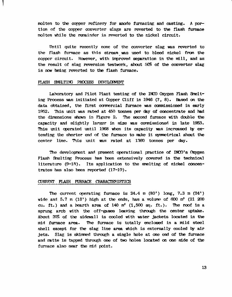
molten to the copper refinery for anode furnacing and casting. A portion of the copper converter slags are reverted to the flash furnace molten while the remainder i s reverted to the nickel c i r c u i t .
Until quite recently none of the converter slag was reverted to the flash furnace as this stream was used to bleed nickel from the copper c i r c u i t . However, with improved separation in the m i l l , and as the result of slag reversion testwork, about 50% of the converter slag i s now being reverted to the flash furnace.
FLASH SMELTING PROCESS DEVELOPMENT
Laboratory and Pilot Plant testing of the INOO Oxygen Flash Smelting Process was initiated at Copper C l i f f in 1946 (7, 8). Based on the data obtained, the f i r s t commercial furnace was commissioned in early 1952. This unit was rated at 450 tonnes per day of concentrate and had the dimensions shown in Figure 2. The second furnace with double the capacity and slightly larger in size was commissioned in late 1953. This unit operated until 1968 when i t s capacity was increased by extending the shorter end of the furnace to make i t symmetrical about the center line. TTiis unit was rated at 1360 tonnes per day.
The development and present operational practice of INCO's Oxygen Flash Smelting Process has been extensively covered in the technical literature (9-18). Its application to the smelting of nickel concentrates has also been reported (17-19).
CURRENT FLASH FURNACE CHARACTERISTICS
The current operating furnace i s 24.4 m (80*) long, 7.3 m (24') wide and 5.7 m (18*) high at the ends, has a volume of 600 ms (21 200 cu. ft.) and a hearth area of 140 m2 (1,500 sq. f t . ) . The roof i s a sprung arch with the off-gases leaving through the center uptake. About 20% of the sidewall i s cooled with water jackets located in the mid furnace area. The furnace i s totally enclosed in a mild steel shell except for the slag line area which i s externally cooled by air jets. Slag i s skimmed through a single hole at one end of the furnace and matte i s tapped through one of two holes located on one side of the furnace also near the mid point.
13

The furnace refractories consist of a magnesite bottom and chrome magnesite in the walls and roof.
FLUID BED DRYING OF COPPER CONCENTRATES
At Copper C l i f f , the concentrates, at about 8% moisture, are delivered by conveyor along with about 10% sand flux to the top of the f l u i d bed dryer. These units are fired by natural gas, though light o i l has also been used. The dried product, at about 0.1% moisture, i s conveyed by the fluidizing a i r to the baghouses where the furnace feed i s collected for delivery to the furnace feed bins. The flowsheet i s shown in Figure 3.
There are two dryers each, nominally 2.4 m (8 1) diameter at the hearth with fluidizing shafts about 4.9 m (16') high. They are each capable of drying about 900 tonnes per day of concentrate. The windbox temperature i s typically 315°C (600°F) the bed temperature 120°C (250°F) and the off-gas 105°C (200°F). The fluidizing blowers have a capacity of 37 600 Itas/hr (25 000 SCFM) and the combustion chamber rating i s 5.2 x 10s cal/hr (20.5 x 10* Btu/hr).
The dust loading at the baghouse inlet i s typically about 900 G/Nms (370 Gr/SCF) while the outlet i s about 0.5 G/Nms (0.19 GR/SCF) for a dust collection efficiency of about 99.95%. The unit i s designed to handle about 49 000 Nta'/Hr (32 500 SCFM) with typical inlet and outlet temperatures of 105°C (220WF) and 90°C (195°F) respectively. The bag differential varies between 0.5-2.0 KPA (2-9" WC) depending on the condition of the bags, which are typically changed once per year.
FLASH SMELTING OF COPPER CONCENTRATES
The flash smelting flowsheet i s also depicted in Figure 3. The dried feed, from the baghouse hoppers, i s delivered by screw conveyors to feed bins located above and at either end of the furnace. In addition to the feed bins, recycle dust and touch up flux bins are also located in this area. The dust collected in the furnace off-gas s e t t l ing chamber and in the copper converter c o t t r e l l are both recycled to the furnace. The touch up flux i s used as required to make minor
14

adjustments to the s i l i c a content of the furnace slag hut i s now also used to raise the s i l i c a level of the molten converter slag recycle, which enters the furnace at about 20% S i 0 2 and i s discharged at about 32% S i 0 2 . The furnace feed rate i s controlled by variable flow control valves associated with weightometers located under these bins. The feed materials are then transported by screw conveyors to drop pipes which discharge directly into the furnace burners. In these burners the f a l l i n g feed i s injected into the furnace by a horizontal flowing stream of oxygen. The oxygen flow i s ratioed to the burner feed rate and at Copper C l i f f i s currently 20-21% weight of the feed.
A cut-away view of the flash furnace i s shown in Figure 4. The feed i s delivered as just described to four concentrate/oxygen burners, two located at each end of the furnace. These burners are water jack-etted. Spontaneous ignition occurs with the oxygen reacting with part of the sulfur and iron in the concentrate to form S0 2 and iron oxides. S i l i c a , contained in the flux and concentrate, combines with these oxides to form slag. Copper, except for the minor amount lost in the slag, and the remaining iron and sulfur collect in the matte. The converter slag i s reverted down a launder into the end of the furnace opposite to the slag skimming hole. The off-gases leave through the furnace uptake and pass to the adjacent settling chamber.
The oxygen/concentrate reactions supply a l l the heat required by the process so no extraneous fuel i s required - or in other words, the smelting operation in the INCO furnace i s totally autogenous.
Our current experience has given us three years l i f e on the furnace refractory though with recent modifications we are expecting four or possibly five years l i f e . The furnace bottom has never shown any evidence of magnetite build up and i s the original bottom installed in 1953 except for the portion added during the 1968 extension. It has been in use for almost thirty years and shows no sign of failure.
The slag i s skimmed from one end of the furnace. This operation i s only carried out with a f u l l hole to preclude the possibility of the escape of furnace gases. The hole i s fitted with a vent hood as i s the launder and hood over the slag pot. This launder i s water cooled.
15
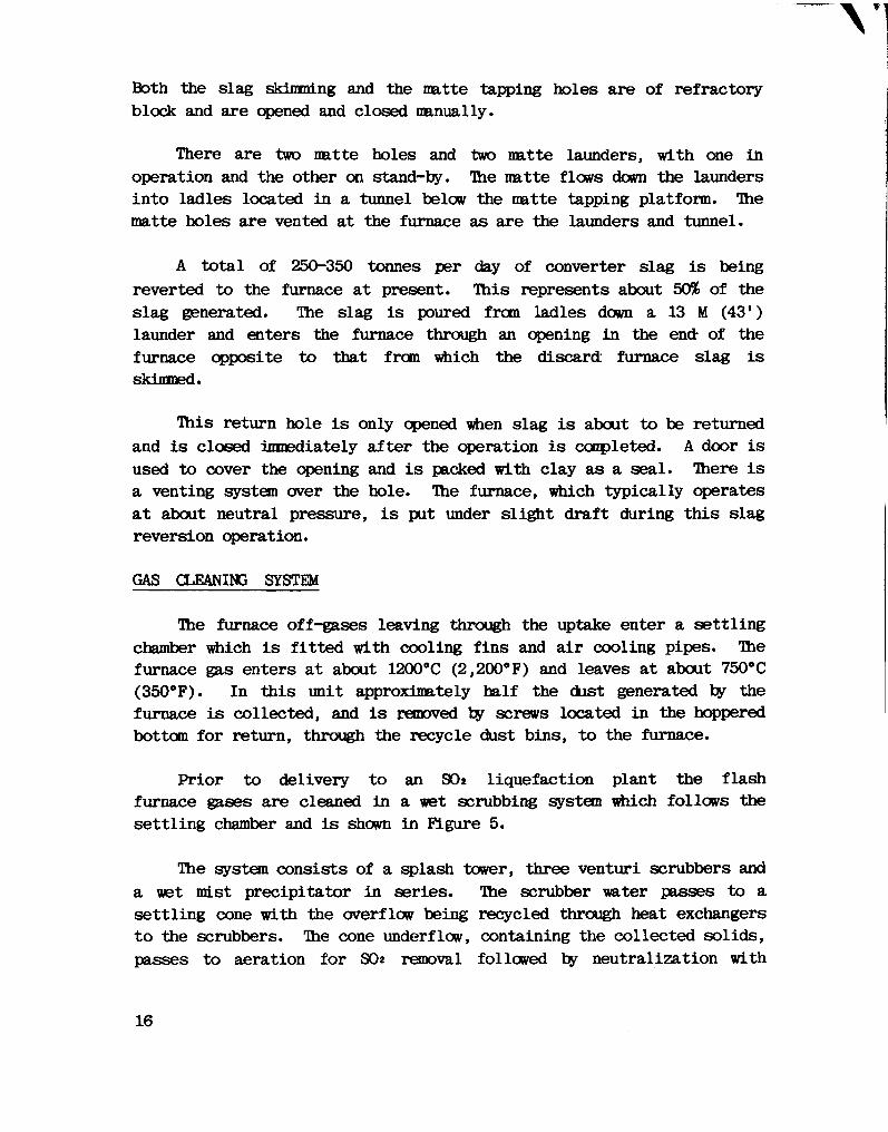
Both the slag skimming and the matte tapping holes are of refractory block and are opened and closed manually.
There are two matte holes and two matte launders, with one in operation and the other on stand-by. The matte flows down the launders into ladles located in a tunnel below the matte tapping platform. The matte holes are vented at the furnace as are the launders and tunnel.
A total of 250-350 tonnes per day of converter slag i s being reverted to the furnace at present. This represents about 50% of the slag generated. The slag i s poured from ladles down a 13 M (43 1) launder and enters the furnace through an opening in the end- of the furnace opposite to that from which the discard furnace slag i s skimmed.
This return hole i s only opened when slag i s about to be returned and i s closed immediately after the operation i s completed. A door i s used to cover the opening and i s packed with clay as a seal. There i s a venting system over the hole. The furnace, which typically operates at about neutral pressure, i s put under slight draft during this slag reversion operation.
GAS CLEANING SYSTEM
The furnace off-gases leaving through the uptake enter a settling chamber which i s f i t t e d with cooling fins and a i r cooling pipes. The furnace gas enters at about 1200°C (2,200°F) and leaves at about 750°C (350°F). In this unit approximately half the dust generated by the furnace i s collected, and i s removed by screws located in the hoppered bottom for return, through the recycle dust bins, to the furnace.
Prior to delivery to an SO2 liquefaction plant the flash furnace gases are cleaned in a wet scrubbing system which follows the settling chamber and i s shown in Figure 5.
The system consists of a splash tower, three venturi scrubbers and a wet mist precipitator in series. The scrubber water passes to a settling cone with the overflow being recycled through heat exchangers to the scrubbers. The cone underflow, containing the collected solids, passes to aeration for SO2 removal followed by neutralization with
16

lime and return to the Copper C l i f f concentrator for recycling (20). The cleaned furnace off-gas i s delivered to a liquefaction plant operated by Canadian Industries Limi ted (21).
If the furnace gases were to be used for sulfuric acid production the recommended gas cleaning system would consist of a water spray cooler to lower the gas temperature to about 320°C (600°F) followed by an electrostatic precipitator.
FLASH FURNACE OPERATIONAL DATA
The furnace feed rate has been varied from about 700 to 1500 tonnes per day as production requirements dictate. These changes can be easily achieved by shutting off either one, two or even three of the burners. Rates of over 1800 tonnes per day have been attained with the ultimate capacity of the unit s t i l l not established because of limitations external to the furnace such as concentrate and oxygen a v a i l a b i l i t y , material handling constrictions, converter capacity, anode casting capability, etc. A turn-down of almost 3-1 i s achievable very readily and quickly.
At a rate of 1200 tonnes per day the specific smelting rates are 200 tonnes per day/100 ms (62 STPD/1000 cu. ft.) of furnace volume or 8.6 tonnes per day/m2 (0.9 STPD/sq. ft . ) of hearth area.
Typically the furnace holds 100-200 tonnes of matte and 100-150 tonnes of slag. The matte i s tapped at about 1170°C (2140°F) and the slag i s skimmed at about 1230°C (2240°F) while the off-gases also leave at about 1230°C (2240°F).
Because commercial oxygen, at about 97% purity, i s used in the furnace, off-gases from the furnace are very low, averaging only 140¬170 ms /tonnes of concentrate (4500-5500 SCFM/ST). As a result of the low volumes being produced by the furnace, the furnace uptake velocit i e s are only 1 m/s (3-4'/sec) so the dusting rate from the furnace i s also very low, at only 2-3% of the concentrate rate. The gas handling and cleaning system i s also small. In our opinion the small off-gas volume and therefore i t s small heat content do not j u s t i f y the i n s t a l lation of a waste heat recovery system.
17

The refractory u t i l i z a t i o n during our most recent campaign amounted to 1.1 kg/tonnes feed (2.0 lbs/ST). This includes a l l the refractory installed in the furnace and i t s associated equipment at the time of the major rebuild prior to the campaign and the minor amounts installed during the campaign i t s e l f .
PROCESS METALLURGY
INTRODUCTION
As already discussed INOO oxygen flash smelting i s an autogenous process. The finely divided sulfide-concentrate, carried by the oxygen, ignites and burns as soon as i t enters the furnace. The oxygen-concentrate reactions are extremely fast.
FLASH SMELTING FLAME CHARACTERISTICS
Observation of the oxygen-copper concentrate flame at INOO's research stations during a pilot plant flash smelting campaign conducted in a top blown rotary converter shows visible ignition of the concentrate occurs at a very short distance from the tip of the burner. Sampling this flame as a function of distance from the burner tip, to investigate how fast the reactions are occurring, has been carried out.
It was found that at about 1 m from the burner the 902 content of the gas was 75%, proving that most of the oxygen had already reacted. At two metres only slag was collected in the sampling steel spoon, indicating that the matte was liquid. The slag sample had the same composition as the slag in the converter, aside from matte p r i l l s . This evidence showed that the reactions in the oxygen flame are extremely rapid and occurred in under one-tenth of a second (22).
FLASH SMELTING CHEMICAL REACTIONS
On Table 1 are listed the main chemical reactions which take place in flash smelting. Also shown in this table are the corresponding heats of reaction. The heat generated in the flash smelting flame corresponds mainly to the combustion of the labile sulfur and FeS. A
18
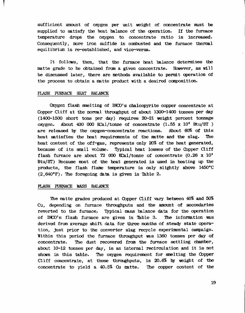
sufficient amount of oxygen per unit weight of concentrate must be supplied to satisfy the heat balance of the operation. If the furnace temperature drops the oxygen to concentrate ratio i s increased. Consequently, more iron sulfide i s combusted and the furnace thermal equilibrium i s re-established, and vice-versa.
It follows, then, that the furnace heat balance determines the matte grade to be obtained from a given concentrate. However, as w i l l be discussed later, there are methods available to permit operation of the process to obtain a matte product with a desired composition.
FLASH FURNACE HEAT BALANCE
Oxygen flash smelting of INOO's chalcopyrite copper concentrate at Copper C l i f f at the normal throughput of about 1300-1400 tonnes per day (1400-1500 short tons per day) requires 20-21 weight percent tonnage oxygen. About 430 000 KCal/tonne of concentrate (1.55 x 10s Btu/ST ) are released by the oxygen-concentrate reactions. About 60% of this heat satisfies the heat requirements of the matte and the slag* The heat content of the off-gas, represents only 20% of the heat generated, because of i t s small volume. Typical heat losses of the Copper C l i f f flash furnace are about 72 000 KCal/tonne of concentrate (0.26 x 10⁶
Btu/ST) Because most of the heat generated i s used in heating up the products, the flash flame temperature i s only slightly above 1450°C (2,640°F). The foregoing data i s given in Tkble 2.
FLASH FURNACE MASS BALANCE
The matte grades produced at Copper C l i f f vary between 40% and 50% Cu, depending on furnace throughputs and the amount of secondaries reverted to the furnace. Typical mass balance data for the operation of INCO's flash furnace are given in Tkble 3. The information was derived from average shift data for three months of steady state operation, just prior to the converter slag recycle experimental campaign. Within this period the furnace throughput was 1360 tonnes per day of concentrate. The dust recovered from the furnace settling chamber, about 10-12 tonnes per day, i s an internal recirculation and i t i s not shown in this table. The oxygen requirement for smelting the Copper C l i f f concentrate, at these throughputs, i s 20.6% by weight of the concentrate to yield a 40.5% Cu matte. The copper content of the
19

slag, 0.57%, i s typical of this operation. The data collected during many years of operation show that the slag losses in the flash furnace are directly proportional to matte grades, the best correlation being
% Cum % Qig = 70 + 10
This copper partition coefficient i s valid for matte grades up to about 55% Cu.
COMPOSITION OF FURNACE OFF-GAS
The use of commercial oxygen in flash smelting results i n a small volume of off-gas with a high SOz content, as shown in Table 4. Oxygen efficiency in the flash furnace i s 100%. Because there i s some a i r in-leakage into the furnace, the composition of the gas in the furnace uptake i s typically 83% S O 2 . After cooling and cleaning, the gas analyzes 75% to 80% S O 2 , because of the additional a i r dilution which normally occurs during gas treatment.
The high strength gas i s used at Copper C l i f f for producing liquid SO2. In most cases, this gas w i l l provide an excellent continuous base load for a sulfuric acid plant as can be noted from the following data.
The sulfur distribution in a hypothetical INOO flash smelting operation i s shown in Figure 6. Hie smelter feed i s a chalcopyrite concentrate analyzing 28% Cu, 29% Fe and 32.6% S which yields a 50% Cu matte at a throughput of 1100 tonnes per day.
In the flash smelting operation, 57% of the sulfur i s eliminated from the concentrate as a strong, low volume gas stream. Except for the minor amount in the slag, the remainder of the sulfur reports to the matte and i s eliminated during conversion. The best designed converter hoods cannot avoid a gas dilution of at least 100%. Further dilution in the gas treatment line makes i t d i f f i c u l t to attain an average SO2 content in these converter gases exceeding about 4.5%. However, the gas resulting from blending the flash furnace gas with the converter gas increases the strength of the feed to the acid plant to almost 10%.
20

Today a number of conventional reverb smelters are processing their converter gases in acid plants. The same acid plants, with only minor modifications, could achieve fixation of almost a l l of the sulfur input to these smelters i f the reverb furnaces were replaced with oxygen flash furnaces. In fact the combined flash furnace-converter gas, at about twice the SO2 strength of the converter gas alone, would have a smaller volume than that of the converter gases from reverb smelting, because of the higher matte grade which the flash furnace would yield. In addition, the blended gas would provide a much steadier feed to the acid plant.
MOLTEN CONVERTER SLAG RECYCLE
As previously explained, the presence of NL in the Cu concentrate and the Cu in the Ni concentrate results in substantial intercircuit transfer streams at the Copper C l i f f smelter. Copper converter slags are an important bleed for nickel from the copper c i r c u i t . Until very recently, 100% of these slags were reverted to the nickel reverb furnaces.
However, this practice greatly complicated the t r a f f i c along the converter aisle. It was thought, then, that at least partial reversion of the copper converter slags to the flash furnace could alleviate this problem. At the same time, the question of the capability of the INOO flash smelting furnace for cleaning converter slags had been raised. An experimental campaign was then conducted at Copper C l i f f early in 1978 to answer these questions.
For this purpose one of the furnace burners was removed from the wall closest to the converter aisle to provide a converter slag recycle port. The slag was poured into the furnace via a 13 m (43*) long launder. During the experimental campaign, which lasted for almost two months, the furnace operated on only three burners at an average throughput of 1300 tonnes per day with a maximum of 1630 tonnes per day.
The mass balance data shown in Table 5 reflects a seven-day operating period during which the average converter slag recycle to the
21
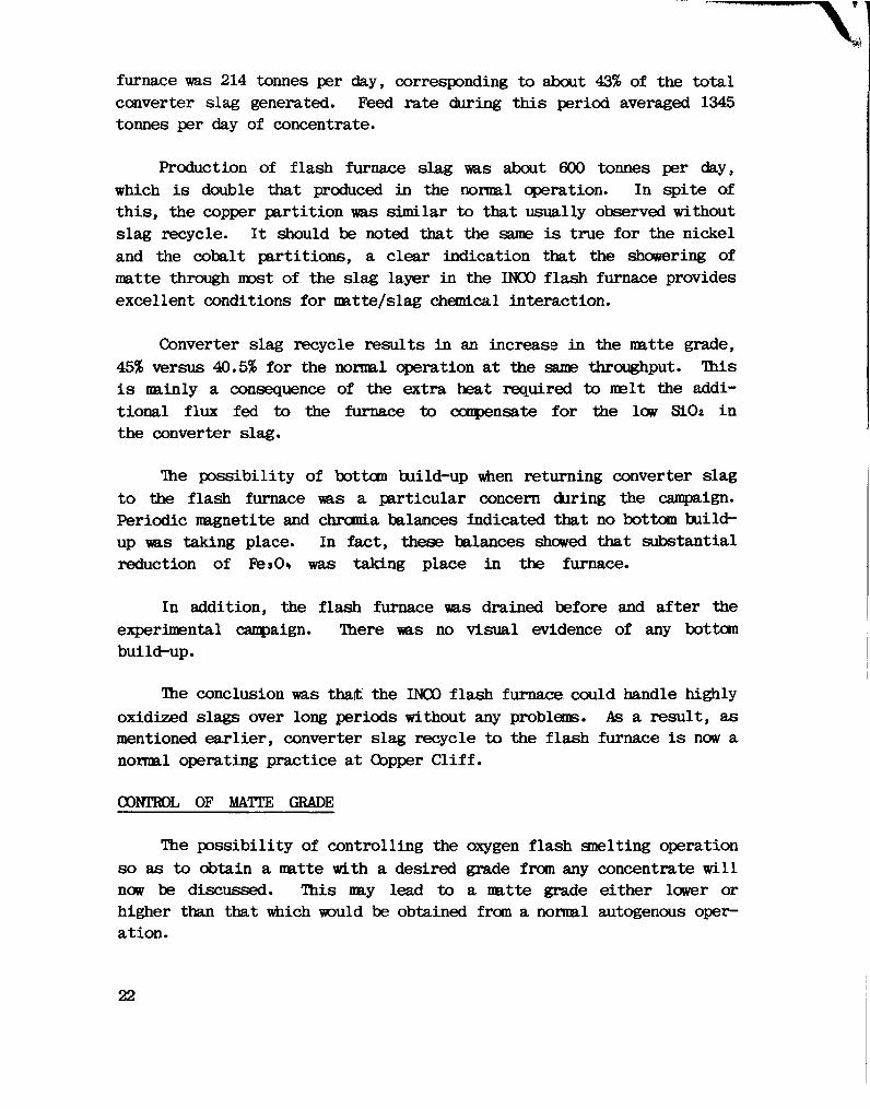
furnace was 214 tonnes per day, corresponding to about 43% of the total converter slag generated. Feed rate during this period averaged 1345 tonnes per day of concentrate.
Production of flash furnace slag was about 600 tonnes per day, which i s double that produced in the normal operation. In spite of this, the copper partition was similar to that usually observed without slag recycle. It should be noted that the same i s true for the nickel and the cobalt partitions, a clear indication that the showering of matte through most of the slag layer in the INOO flash furnace provides excellent conditions for matte/slag chemical interaction.
Converter slag recycle results in an increase in the matte grade, 45% versus 40.5% for the normal operation at the same throughput. This i s mainly a consequence of the extra heat required to melt the additional flux fed to the furnace to compensate for the low Si02 i n the converter slag*
The possibility of bottom build-up when returning converter slag to the flash furnace was a particular concern during the campaign. Periodic magnetite and chromia balances indicated that no bottom buildup was taking place. In fact, these balances showed that substantial reduction of Pes O h was taking place in the furnace.
In addition, the flash furnace was drained before and after the experimental campaign. There was no visual evidence of any bottom build-up.
The conclusion was that the INOO flash furnace could handle highly oxidized slags over long periods without any problems. As a result, as mentioned earlier, converter slag recycle to the flash furnace i s now a normal operating practice at Copper C l i f f .
CONTROL OF MATTE GRADE
The possibility of controlling the oxygen flash smelting operation so as to obtain a matte with a desired grade from any concentrate w i l l now be discussed. This may lead to a matte grade either lower or higher than that which would be obtained from a normal autogenous operation.
22

Small additions of coal to the feed, less than 1%, result in substantial decreases in matte grade of from 10 to 15 percentage points depending on the composition of the feed. This possibility was established when Thompson copper concentrates, which contain several percentage points graphite, were flash smelted as part of the Copper C l i f f furnace charge. The graphite was totally combusted in the furnace. We have simulated this type of operation, at INOO's pilot plants and in a mini-plant flash smelting installation which we have at INOO's research laboratory, with excellent and predictable results.
Increasing the matte grade can be achieved by the addition of revert materials, such as dust, ground matte and slag skulls, etc., to the feed or injection of water into the furnace. A l l these alternatives consist of introducing a coolant into the system to consume the heat which would be generated above that corresponding to a normal autogenous operation. Because of this, they have the limitation of not being energy efficient. A second alternative consists of roasting part of the concentrate and flash smelting a blend of the resulting calcine with the remainder of the green concentrate. The desired composition of the matte to be obtained can be controlled by adjusting the ratio of calcine to green concentrate in the feed. What this technique actually does i s to adjust the fuel value of the feed to that required to yield the desired matte grade on autogenous oxygen flash smelting.
Testwork on autogenous oxygen flash smelting of various blends of roasted and unroasted copper sulfide concentrate with the compositions shown in Table 6 was conducted in a mini-plant furnace at INOO's J.R.G. Research Laboratory. The Cu and the Fe in the calcine were mainly as copper f e r r i t e , CuFe20%. Minor amounts of CuO and FesO% were also present. The amount of oxygen required to simulate a commerc i a l autogenous operation was calculated from heat and mass balances which predicted the commercial matte grades which would be obtained at the various experimental calcine/green concentrate ratios. The actual matte grades obtained, as shown in Table 6, were very close to those expected. The slag compositions are also shown.
In these tests i t was observed that ignition and combustion of the green concentrate was not affected by the dilution with calcine. The slags were fluid and good separation of mattes and slags was observed.
23

The matte/slag Cu partition for the 50% Cu matte was similar to that observed at Copper C l i f f . At higher matte grades the Cu partition decreased. However, more testwork i s .required before developing data which are s t a t i s t i c a l l y meaningful.
In summary this development offers some interesting advantages:
(a) With respect to conventional autogenous oxygen flash smelting.
- The possibility of obtaining a product with a desired composition regardless of the composition of the concentrate and furnace throughput. There i s potential here for producing white metal or even bl i s t e r copper in a one step smelting operation.
(b) With respect to alternative methods for controlling the matte grade by adding coolant.
- Less oxygen consumption to obtain the same matte from a given concentrate.
- A higher specific capacity of the furnace.
- Less dusting.
This mode of operation makes INOO oxygen flash smelting a very flexible process, in particular for processing low grade concentrates, normally high in pyrite, which on conventional oxygen flash smelting would yield low grade mattes.
PROCESS ECONOMICS
INTRODUCTION
The process economics of INCO oxygen flash smelting are based on the treatment of a typical B.C. concentrate and include a review of a proposed operation with i t s mass balance, direct process energy requirements and i t s estimated operating and capital costs.
24

PROCESS MASS BALANCE
The simplified mass balance for the treatment of 1360 tonnes per day (1500 STPD) of a typical B.C. concentrate i s shown on Table 7. It has been assumed that f u l l molten converter slag, furnace dust and converter dust recycle would be practised.
The assumed concentrate analysis i s 30% Cu, 24% Fe, and 30% S. There i s sufficient Si02 in this concentrate to make i t self fluxing. The oxygen requirement amounts to about 20% of the concentrate weight. Autogenous operation w i l l yield a matte containing about 55% Cu, and a discard slag containing less than 0.8% Cu. The furnace o f f -gases w i l l contain about 80% SO2 and amount to about 7700 lto s/hr (5100 SCFM). The copper recovery of the process i s 98.6%.
DIRECT PROCESS ENERGY REQUIREMENTS
On the basis of the foregoing mass balance, the direct energy requirements for the flash smelting and converting operations have been estimated. The approach taken i s conservative and i t i s believed that a detailed analysis would decrease rather than increase the figures shown in Table 8.
In the drying and smelting area the only fuel requirement i s for concentrate drying. A moisture of 12% was assumed for the concentrate and i t w i l l therefore require about 470 000 Btu/ST concentrate. The process el e c t r i c a l requirements can be broken down into three major areas. Power for oxygen production, based on 360 Kwh/ST at 20.2% by weight of the concentrate, amounts to 74 Ifrh/ST concentrate. Other process power, based on our Copper CLiff experience, amounts to about 23 Kwh/ST concentrate, while furnace gas cleaning i s about 3 Kwh/ST concentrate, for a total of 100 K^h/ST concentrate. Using the genera l l y accepted factor of 10 500 Btu/Kwh, which i s for thermally generated power, this becomes 1.05 million Btu/ST concentrate. The total drying and smelting energy requirement for the B.C. concentrate i s thus the 1.52 million Btu/ST.
In the converting area, assuming the feed i s the 55% CU furnace matte, the estimated direct process energy requirements are also shown in Table 8. The holding f i r e requirements are based on 212 000 Btu/ST
25

of matte treated while the electrical power for blast a i r and gas cleaning are based on 1.4 Ksvh/1000 SCF and 0.43 Kvh/1000 SCF respectively. These factors are those used by H.H. Kellogg and J.M. Henderson in their paper entitled "Energy Use in Sulfide Smelting of Copper". An allowance has been added for other items such as material handling, crane transfers, converter rotation, etc. This yields a total converting energy requirement of 620 000 Btu/ST concentrate.
The total drying, smelting and converting direct process energy requirements are therefore estimated at 2.14 million Btu/ST concentrate compared with figures in the 4-5 million range for a standard reverb/ converter operation. Of this 2.14 million figure approximately 72% i s for power and 28% i s for conventional fuel.
As noted above this total i s based on the 10 500 Btu/Kwh factor which i s for thermally generated power (23, 24). In B r i t i s h Columbia where almost a l l power i s hydro based a more r e a l i s t i c factor might be 3 400 Btu/Kwh. Using this figure the total process energy requirements for drying, smelting and converting using the INOO Oxygen Flash Smelting Process are only 1.1 million Btu/ST.
OPERATING COST ESTIMATE
The total energy requirements are, of course, an important factor i n process selection, however, to the producer the major concern i s the total cost of the process energy. Table 9 shows an approximate direct operating cost for the INOO oxygen flash furnace treating 1360 tonnes per day (1500 short ton per day) or 449 000 tonnes per year (495 000 short ton per year) of B.C. concentrate.
The costs shown are for the drying and smelting portion of the process only and exclude a l l indirect and overhead costs which w i l l vary substantially depending on location and philosophy.
Only 8 men per shift are required to operate this area which at a cost of $25,000 per man, totals about $900,000/yr. The front line supervision w i l l be $180,000/yr. The natural gas for drying the concentrate, at an assumed price of $2.50/1000 SCF, w i l l cost $460,000/yr. Direct electrical power, at 2.0 cts/Kwh, totals $270,000, while the
26
tonnage oxygen, estimated at $15/ST, totals $l,530,000/yr. Both the natural gas and power costs used in this estimate are, i t i s believed, conservative for a B.C. location.
Repair labour, supervision and supplies, including refractory for major rebuilds every three years, have been calculated at $1,100,000/yr An allowance for miscellaneous operating supplies of $150,000/yr. and a contingency of 10% have been included to arrive at a total of $5.05 million/yr.
This amounts to $11.25/tonne ($10.20/ST) of concentrate or 1.7 cts./lb. Cu in matte. Total copper production would be about 290 million lb/yr (132 000 tonnes per year). The total energy charges amount to less than 33% of this total or $3.66/tonnes ($3.32/ST) or less than 0.6 cts./lb. CU.
CAPITAL COST ESTIMATE
A pre-feasibility type capital cost, which has a process scope from receipt of the wet feed at the storage bins through to matte and slag in the furnace launders and the off-gas cleaned ready for delivery to an acid plant, has been estimated. It i s based on a greenfield site in North America but does not include any items outside the Immediate drying and smelting area, except for a turn key oxygen plant (270 tonne or 300 STPD), which i s included. No working capital, escalation through construction, insurance and taxes, finance charges and the like are included.
The figures are as shown in Table 10, and total approximately $35 million, of which about $15 million i s for the oxygen plant and $20 million for the process area. It should be noted that no capital expenditures are required for slag cleaning or waste heat recovery equipment while attaining over 98.5% copper recovery with a totally autogenous smelting operation.
SUMMARY
MAJOR ADVANTAGES OF INOO OXYGEN FLASH FURNACE
The major advantages of the INOO oxygen flash furnace f a c i l i t y can be summarized as follows:
27
(1) The process f a c i l i t y requires a low capital cost investment because of i t s simple construction and relatively small size. The furnace structure i s entirely independent of the building. The production rate per unit volume i s from 3 to 10 times that for such conventional units as reverbs and elect r i c furnaces. Capital expenditure i s not ju s t i f i e d for waste heat recovery because the heat that can he recuperated i s very small.
(2) The gas cleaning equipment capital costs are low because the off-gas volume from the furnace i s only 130 Nms/m (or 5000 SCFM) for a 1360 tonnes per day (1500 STPD) operation. This i s only one-fifth or less of that for other conventional processes. Because of the low volume, the gas velocities in the furnace are low and, as a result, the furnace dusting rates are low, typically 2-3% of feed at our Copper C l i f f operation. Therefore, the capital expenditure for dust handling i s also low.
(3) The capital cost for sulfur fixation i s also low. After gas cleaning the off-gas strengths are typically 70-80% 90*. This gas i s therefore ideally suited for liquefaction, a cheap fixation process. Alternatively, i t can be used directly as a continuous base load for an acid plant with the minimum of air dilution or ideally as a "sweetener" for other smelter gases, such as converter gas. The use of this low volume, high strength, furnace gas permits the acid plant to be designed to a small overall inlet volume thus making i t s capital costs minimal.
(4) The furnace operating costs are low. There i s only one major operating unit. The drying and smelting operations can be satisfactorily operated with only 7 to 8 operators/shift. Conventional fuel i s required for drying only. The smelting operation requires no fuel. The costs for oxygen w i l l be less than those for conventional fuels.
(5) Over almost thirty years of operation a variety of concentrates, both nickel and copper, have been successfully smelted. The grades of these feeds have varied from 10% to
28

33% CU plus nickel. On occasion, a portion of the furnace feed has been our matte separation copper sulfide concentrate running 72% CU.
(6) With an autogenous operation such as the INOO Process, with a fixed furnace size, a fixed feed rate and a specific concentrate grade one w i l l obtain a specific matte grade. However, the addition of coal in very small amounts w i l l decrease this matte grade, while smelting of blends of roasted and unroast-ed concentrate, or the injection of water w i l l increase this matte grade.
(7) Over a wide range of matte grades (35-55% Cu) the INCO furnace produces a discard slag at a partition coefficient of 70 which typically represents a recovery of 99-99.5% copper. Even during converter slag recycle operation this high p a r t i tion coefficient can be duplicated, though, of course, copper recoveries f a l l to the 98-99% range, because of the increased slag quantities discarded. The demonstrated high partitions eliminate the need for separate slag cleaning f a c i l i t i e s . Up to 50% of the iron in the concentrate leaves with the furnace slag i f no converter slag recycle i s practised; however, this increases to 100% with f u l l converter slag recycle.
(8) The furnace operation i s very simple. Hie major control i s the oxygen/concentrate ratio. INOO monitors the slag and matte temperatures and makes minor adjustments to this ratio as necessary. Should the slag temperature f a l l the oxygen/ concentrate ratio i s increased slightly and vice-versa. The
operation i s so simple that no computer control i s necessary. Furnace feed rate turn downs of about three to one can be readily and rapidly achieved by shutting down one, two or even three burners.
(9) The furnace has been extremely reliable over i t s many years of operation. The Copper C l i f f units have handled in excess of 8 million tonnes of copper concentrate since 1953. Refractory l i f e at the sidewalls i s now three years between major rebuilds but i t i s expected that this figure w i l l be

exceeded during the current campaign. No magnesite build up on the hearth has been experienced even during the current converter slag recycle operation. This slag reversion has been a standard operating practise at Copper C l i f f for almost a year and a half. The original 1953 hearth i s s t i l l in use.
REFERENCES
(1) "Smelting: I. Copper C l i f f Smelter", Canadian Mining Journal, pp 431^145, May, 1946.
(2) "Metallurgical Improvements in the Treatment of Copper-Nickel Ores", The Staff, International Nickel Company of Canada (Presented by P. Oueneau), CIM Transactions, Vol.51, pp 187-198, 1948.
(3) "Extractive Metallurgy at International Nickel - A Half Centre of Progress", L.S. Renzoni, Canadian Journal of Chemical Engineering, February, 1969.
(4) "The Sudbury Operations of INCO Metals 06.", W. Schabas, Canadian Mining Journal, May, 1977.
(5) "Treatment of Nickel-Copper fcfette", K. Sproule, G.A. Harcour and L. S. Renzoni, Journal of Metals, Vol. 12, No.3, pp 214-219, March, 1960.
(6) "Converter Operating Practice at the Copper C l i f f Smelter of the INOO Metals Company", R.J. Neal, R.A. Reyburn, INCO Metals Company presented at 108th AIME Annual Meeting, New Orleans, Louisiana, February, 1979.
(7) "Flash Smelting of INOO Ores Creates New Industry", Northern Mining, July 8, 1948.
(8) "Autogenous Smelting of Sulfides", J.R. Gordon, O.H.C. Norman, P.E. Oueneau, W.K. Sproule and C.E. Young, U.S. Patent 2,668,107 f i l e d June 25, 1949, issued February 2, 1954.
30

(9) "The Oxygen Flash Smelting Process of the International Nickel Company", The Staff, CIM Transactions, Vol.58, pp 158-166, 1955.
(10) "Oxygen Flash Smelting Swings Into Commercial Operation", The Staff, International Nickel Company of Canada, Journal of Metals, Vol.7, pp 742-750, June, 1955.
(11) "Recent Developments in the INOO Oxygen Flash Smelting Process", S. >ferla, C.E. Young and J.w. Msitousek, 101st AIME Annual Meeting, San Francisco, 1972.
(12) "Copper Smelting by the International Nickel Company of Canada", The Staff, Copper C l i f f Smelter, International Symposium on Copper Extraction and Refining, Las Vegas, 1976, in Extractive Metallurgy of Copper, Vol. 1, ed. by J.C. Yannopoulos and J.C. Agarwal, IMS-ABIE, pp 218-233, 1976.
(13) "Flash Smelting", J.W. Matousek, Seminar on Extractive Metallurgy of Copper, McGill University, Montreal, Canada, January, 1977.
(14) "The INCO Oxygen Flash Snelting Process", C. Diaz, INCO Metals Company, Process Development, Seminar on Copper Metallurgy, Bogota, Colombia, February, 1978.
(15) "Tonnage Oxygen for Nickel and Copper Smelting at Copper C l i f f " , R. Saddington, W. Cur look and P. Queneau, Journal of Metals, A p r i l , 1966, Vol.18, No.4, pp 440- 152.
(16) "Operation of the INOO Flash Smelting Furnace with Recycle of Converter Slags", T.N. Antonioni, A.D. Church, C. Iandolt and F. Partelpoeg, 18th Annual Conference of Metallurgists, CIM Sudbury, August, 1979.
(17) "INOO's Oxygen Flash Smelting Process for Copper and Nickel Concentrates", CM. Diaz, H.C Garven, M.Y. Solar, INOO ffetals Company, Process Research, November, 1978.
(18) "INCO's Oxygen Flash ftnelting Process for Copper and Nickel Concentrates; Off-Gas Handling and Impurity Distributions",
31
M.Y. Solar, A.D. Church, T.N. Antonioni, INOO Metals Company, EPA Symposium on Control of Particulate Fmissions in the Primary Non-Ferrous Metals Industries, Monterey, California, March, 1979.
(19) "Smelting Nickel Concentrates in INOO's Oxygen Flash Furnace", M.Y. Solar, R.J. Neal, T.N. Antonioni, M.C. Bell, INOO Metals Company, Journal of Metals, Vol. 31, No. 1, pp 26-32, January, 1979.
(20) "Handling Acid Slurries at the Flash Smelting Plant of the International Nickel Co. of Canada", J.N. L i l l e y , R.W. Chambers C.E. Young, CIM Annual Meeting, Toronto, April, 1960.
(21) "Sulfuric Acid and Liquid Sulfur Dioxide Manufactured from Smelter Gases at Copper C l i f f , Ontario", Trans CIM Vol. LV, 1952, pp 123-125.
(22) "Oxygen Flash Smelting in a Converter", The Staff, INOO Metals Company, Process Research, presented at 106th Annual Meeting, Atlanta, Georgia, March, 1977.
(23) "Energy Use in Sulfide Smelting of Copper", H.K. Kellogg and J.M. Henderson, 105th AIMF Meeting, February, 1976; in Extractive Metallurgy of Copper, J.C. Yannopoulos and J.C. Agarwal, editors, AIME - Metallurgist's Society, 1976, Vol. 1, pp 373-415.
(24) "Pollution Control and Energy Consumption at U.S Copper Smelters", D.A. Schultz, Journal of Metals, January, 1978, with further discussion by H.H. Kellogg and D.A. Schultz, *ay, 1978.
32

TABLE 1
INCO OXYGEN FLASH SMELTING CHEMICAL REACTIONS
CuFeS 2 + 1/20 2 = 1/2Cu 2S + FeS + 1/2S0 2
( C h a I c o p y r I t e )
CusFeS* + 1/20 2 = 5/2Cu 2S + FeS + 1/2S0 2
(Born Ite)
CuS + 1/202 = 1/2Cu 2S + 1/2S0 2
( C o v e l I I t e )
F e S 2 +02= FeS + S0 2
( P y r I t e )
FeS + 3/20 2 = FeO + S0 2
Cu 2S + 3/202 = Cu 20 + S0 2
FeO + I/6O2 = 1/3Fe s0*
FeO + 1/2SI0 2 = 1/2Fe 2Si0i,
H 25*C Kcal/Mol
-23.48
-16.88
-32.57
-54.07
-112.07
-92.34
-24.28
- 4.33
33

TABLE 2
INCO OXYGEN FLASH SMELTING HEAT BALANCE
THROUGHPUT = 1 300-1 400 tonnes per day of c o n c e n t r a t e at 30* Cu, 31$ Fe, and 33$ S
OXYGEN REQUIRED = 20-21 wt % of c o n c e n t r a t e
Kcal/MT BTU/ST DISTRIBUTION CONCENTRATE CONCENTRATE %
HEAT GENERATED
By 0 2/Feed R e a c t i o n s 430 000 1 548 000 100
HEAT REQUIREMENTS
Heat
Furnace
Matte Slag Off-Gas Dust
Heat Losses
182 000 77 000 88 000 1 1 000 72 000
654 000 279 000 318 000 39 000
258 000
42 18 20 3 17
TOTAL 430 000 1 548 000 100
34

TABLE 3
INCO OXYGEN FLASH SMELTING MASS BALANCE FOR OPERATIONS WITHOUT
CONVERTER SLAG RECYCLE (AUGUST TO OCTOBER, 1977)
INPUTS
C o n c e n t r a t e
R e c y c l e Dust
F I ux
Tonnage
RATE DMTPD
1 360
32
95
280 (20.6$)
COMPOSITION - WT Cu
30
42
Fe
31 .0
8.0
2.2
33.5
19.0
S10 2
2.0
1.7
78.0
OUTPUTS
Matte
S I ag
Sludge
Off-Gas
1 .030
295
20
410
40.5
0.57
27.00
28.8
43.0
16.0
24.5
1 .3
18.0 33.0
2.6
PARTITION COEFFICIENT: $ Cu IN MATTE $ Cu IN SLAG = 7 0
35

TABLE 4
FLASH FURNACE OFF-GAS COMPOSITION
(IN VOLUME PERCENT)
SOg jA _N2 CO 2 0_2
AT FURNACE UPTAKE
Without D i l u t i o n 94.5 2.8 1.0 1.7 0 With D i l u t i o n 83.0 2.5 13.0 1.5 0.02
AFTER GAS CLEANING 77 2 20
36

TABLE 5
INCO OXYGEN FLASH SMELTING
MASS BALANCE FOR OPERATION WITH
43$ CONVERTER SLAG RECYCLE
(JANUARY 1978)
INPUTS
C o n c e n t r a t e
R e c y c l e Dust
C o n v e r t e r SIag
F I ux
Tonnage Oxygen
RATE DMTPD
1 ,345
32
214
156
286 (21.3$)
COMPOSITION - WT.$ Cu
30.1
41 .8
6.9
Fe
30.1
7.9
47.9
2.2
33.3
19.7
0.9
S i 0 2
2.0
1.7
18.9
77.8
OUTPUTS
Matte
S I ag
S I udge
Off-Gas
940
598
22
434
45.0
0.68
24.0
25.2
43.5
16.8
24.1
1 .4
18.0
0.3
31 . 1
2.2
$ Cu IN MATTE PARTITION COEFFICIENT j C u , N S L A 6 = 68
37
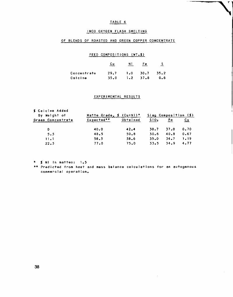
TABLE 6
INCO OXYGEN FLASH SMELTING
OF BLENDS OF ROASTED AND GREEN COPPER CONCENTRATE
FEED COMPOSITIONS (WT.g)
Cu Nl Fe S
C o n c e n t r a t e 29.7 1.0 30.7 35.2 C a l c i n e 35.0 1.2 37.8 0.8
EXPERIMENTAL RESULTS
% C a l c i n e Added By Weight of
Green C o n c e n t r a t e Matte Grade, % (Cu+Ni)* Ex p e c t e d * * Obta i ned
Slag Composition ($) S i 0 2 Fe Cu
0 5.5
11.1 22.5
40.0 48.5 58.5 77.0
42.4 50.8 58.6 75.0
30.7 30.6 35.0 33.5
37.0 40.8 34.7 34.9
0. 70 0.67 1 . 19 4.77
* % Ni in mattes: 1.5 ** P r e d i c t e d from heat and mass balance c a l c u l a t i o n s f o r an autogenous
commercial o p e r a t i o n .
38
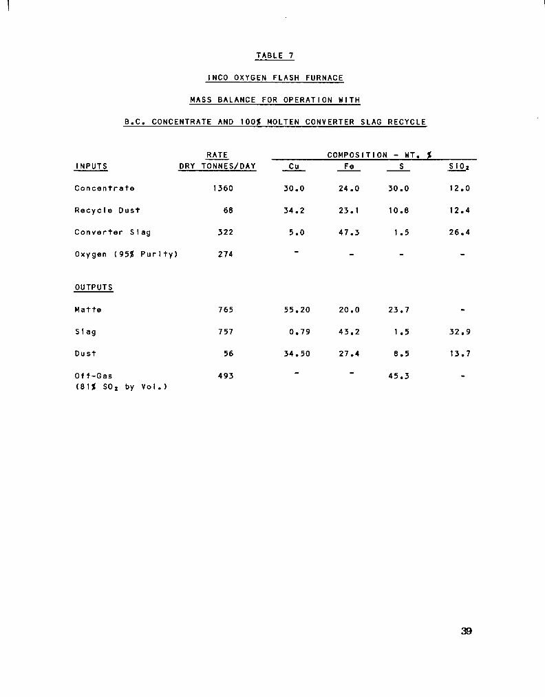
TABLE 7
INCO OXYGEN FLASH FURNACE
MASS BALANCE FOR OPERATION WITH
B.C. CONCENTRATE AND 100$ MOLTEN CONVERTER SLAG RECYCLE
INPUTS
C o n c e n t r a t e
R e c y c l e Dust
C o n v e r t e r SIag
Oxygen (95$ P u r i t y )
RATE DRY TONNES/DAY
1360
68
322
274
COMPOSITION - WT. $ Cu
30.0
34.2
5.0
Fe
24.0
23.1
47.3
30.0
10.8
1 .5
S10 2
12.0
12.4
26.4
OUTPUTS
Matte
S I ag
Dust
Off-Gas (81$ S0 2 by Vol.)
765
757
56
493
55.20
0.79
34.50
20.0
43.2
27.4
23.7
1 .5
8.5
45.3
32.9
13.7
39
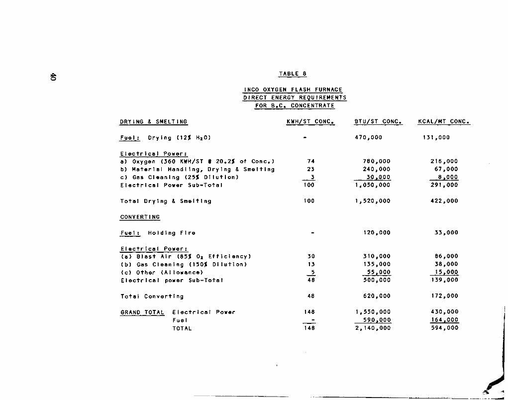
TABLE 8
INCO OXYGEN FLASH FURNACE DIRECT ENERGY REQUIREMENTS
FOR B.C. CONCENTRATE
DRYING & SMELTING KWH/ST CONC.
Fuel : Drying (12$ H 20)
E l e c t r i c a l Power: a) Oxygen (360 KWH/ST % 20.2$ of Cone.) b) M a t e r i a l H a n d l i n g , Drying & Smelting c) Gas C l e a n i n g (25$ D i l u t i o n ) E l e c t r i c a l Power Sub-Total
T o t a l D r ying & S m e l t i n g
CONVERTING
FueI: H o l d i n g F i r e
E l e c t r i c a l Power: (a) B l a s t A i r (85$ 0 2 E f f i c i e n c y ) (b) Gas C l e a n i n g (150$ D i l u t i o n ) (c) Other (Allowance) E l e c t r i c a l power Sub-Total
T o t a l C o n v e r t i n g
GRAND TOTAL E l e c t r i c a l Power Fuel TOTAL
74 23 3
100
100
30 13 5
48
48
148
148
BTU/ST CONC.
470,000
780,000 240,000 30,000
1,050,000
1,520,000
120,000
310,000 135,000 55,000
500,000
620,000
1,550,000 590,000
2, 140,000
KCAL/MT CONC,
131 ,000
216,000 67,000 8 ,000
291,000
422,000
33,000
86,000 38,000 15,000
139,000
172,000
430,000 164,000 594,000

TABLE 9
INCO OXYGEN FLASH FURNACE
APPROXIMATE DIRECT OPERATING COST ESTIMATE
1360 TONNES PER DAY OF CONCENTRATE
(BASIS 1980 COSTS)
S1000/YR.
O p e r a t i n g Labour (8 men/ s h i f t ) 900
O p e r a t i n g S u p e r v i s i o n (1 man/shift) 180
Nat u r a l Gas ($2.50/1000 C.F.) 460
Power (2.0 cts/KWH) 270
Oxygen ($15/ton) 1,530
Repair Labour S u p e r v i s i o n & S u p p l i e s 1,100
M i s c e l l a n e o u s O p e r a t i n g S u p p l i e s 150
Contingency (10$) 460
TOTAL $5.050
OR $11.25/Tonne Cone. 1.7 c t s / l b Cu
NOTES:
(1) 449 000 tonnes per year of c o n c e n t r a t e t r e a t e d .
(2) a p p r o x i m a t e l y 290 x 10* lbs copper/year as b l i s t e r would be produced.
(3) Includes c o s t s of major r e b u i l d every 3 y e a r s .
41

TABLE 10
INCO OXYGEN FLASH FURNACE
APPROXIMATE CAPITAL COST ESTIMATE
1360 TONNES PER DAY OF CONCENTRATE
(BASIS 1980 COSTS)
$ x 1000
A. Proces s P l a n t 1. B u i l d i n g 3,900
2. Equipment 11,000
B. Oxygen P l a n t (Turn Key) 13,500
C. E n g i n e e r i n g , Procurement and P r o j e c t S e r v i c e s 2,800
D. Contingency (20$) 3,600
TOTAL PHYSICAL FACILITIES $34,800
ASSUMES: 1. G r e e n f i e l d s i t e . 2. North American l o c a t i o n . 3. B a t t e r y l i m i t s f a c i l i t y - a l l s e r v i c e s a v a i l a b l e
at the bu i Id i ng waI I s. 4. No waste heat g e n e r a t i o n f a c i l i t i e s . 5. No separate s e r v i c e , maintenance or o f f i c e
f ac i I i t i es. 6. No mobile equipment. 7. No land a c q u i s i t i o n c o s t s , l i c e n s e s , permits,
f e e s . 8. Equity - f i n a n c e d . No i n t e r e s t or f i n a n c e charges
i n c l u d e d . 9. No working c a p i t a l .
10. No owner's management or p r e p r o d u c t i o n o p e r a t i n g c o s t s .
11. No p r o j e c t insurance and t a x e s . 12. No e s c a l a t i o n through c o n s t r u c t i o n .
42

F I G U R E I
COPPER CLIFF SMELTER FLOWSHEET
NICKEL C O N C E N T R A T E Sand
Misceilane ous i ROASTERS
COPPER C O N C E N T R A T E Sand
O A *
Calcin e
NICKEL REVERB FURNACES
ESP Dust
S0 2 to Liquefaction
t
FLUID BED DRYERS
r Slag to
D u m P Matte
Flu Misc
r
—^<
IJT IIINICKEL CONVERTERS
Scrap Slag
r Slag to Dump Matte
« Oxygen COPPER FLASH FURNACE
Flux
II
Misc
Chalcocite Cone from Matte S e p 0
Reverts
Slag [ f | -^mCOOLING Hi • I H i CONVERTERS
r*-7MATTE C A S T I N G
BESSEMER M A T T E to Matte Separation
JjCOPPER CONVERTERS
BLISTER COPPER to Copper Refinery
43

F I G U R E 2
STAGES OF FLASH FURNACE DEVELOPMENT
2.8
450 TPD 1952-1953
910 TPD 1953-1968
7.2m
GAS OFFTAKE TO SETTING CHAMBER
WATER COOLING JACKET
TAP HOLE
a xr a
f 4.6 i
16.1m —4J V
BURNER OPENIf
SKIMMi HOLE
METERS
7.3m*
5.7m

FIGURE 3 FLASH SMELTING FLOWSHEET
S a n d
Concentrate
•T3 n n n q r
« J i ' • i « i , I ; ! i n 1111 i • 1111111 § i
— FLUID BED DRYER
*• Exhau st
B A G H O U S E
DRY FEED STORAGE
Exhau st •Q—•
FROM S E C O N D
FBD
B A G H O U S E
MOLTEN RECYCLE CONVERTER SLAG
G A S OFFTAKE
DRY FEED S T O R A G E
Water Jacket
O x y g e n
FLASH F U R N A C E
O x y g e n
Slag pot^]7 ^ D u m P
COPPER ««-CONVERTERS
Matto Lad le 45
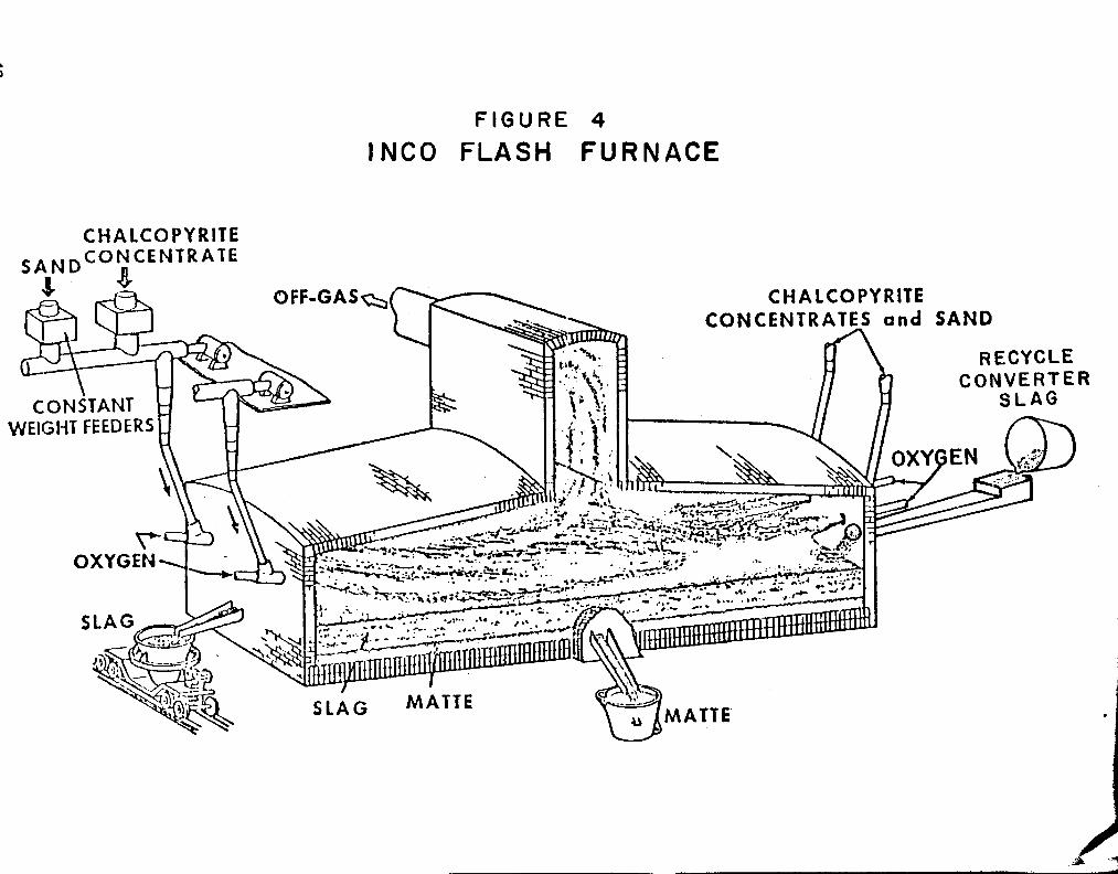
FIGURE 4 INCO FLASH FURNACE
CHALCOPYRITE

FIGURE 5 F L A S H F U R N A C E G A S C L E A N I N G SYSTEM
By-pass Exhaust
Furnace Gases A
i
SETTLING CHAMBER
w Lima Air
i
• •
n SETTLING! CONE:
NEUTRALIZING V A E R A T 0 R
TANK
VENTURI SCRUBBERS
STAND P!PEj-|<—'
1
HEAT E X C H A N G E R S !
STAND PIPE
Fresh Water"
S 0 2 to Liquefaction"*"
Neutral Pulp to Mill Thickener
WET PRECIPITATOR
Acid
47

FIGURE 6
SULFUR DISTRIBUTION IN INCO OXYGEN FLASH SMELTING THROUGHPUT = 1100 MTPD OF CONCENTRATE AT 28%Cu 29%Fe + 32.6%S
S L A G - *
SLAG
FLASH FURNACE
MATTE 5 0 % Cu
CONVERTERS
GAS CLEANING
GAS CLEANING
57 80
41 4-4
60-4
98 9-8 65
TO •-ACID
PLANT
BLISTER S DISTRIBUTION %S02 •VOLUME, 1000 SCFM

SECTION III
THE NORANDA PROCESS
BY G.D. HALLETT*
G.D. HA1LETT, Assistant Manager, Noranda Continuous Smelting Division, Noranda Mines Limited, P.O. Box 45, Commerce Court West, Toronto, Ontario, Canada, M5L 1B6

ABSTRACT
The Noranda Continuous Smelting Process corrmercial plant at Noranda, Quebec has been in operation since fckrch 1973. The operating results have demonstrated the f l e x i b i l i t y of the process in producing either copper or high grade matte from a variety of copper feed materi a l s . No special preparation of the feed i s required. Most of the process energy i s provided by the exothermic heat of the smelting and converting reactions.
The 21.3 ra long by 5.2 m diameter reactor at Noranda was designed for a smelting rate of 726 tons of copper concentrate per day when producing copper without oxygen enrichment of the converting a i r . During a test campaign when the converting air was enriched with oxygen to 30%, and excess oxygen was added above the bath to react with concentrate and matte splash, a smelting rate of 1 560 tonnes of concentrate per day was achieved.
With an 80 tonne oxygen plant the reactor smelts 1 150 tonnes of chalcopyrite concentrate per day and produces a 70%-75% Cu matte with oxygen enrichment of the air to approximately 23%. Fuel can be supplied by o i l or natural gas burners, or by the addition of coal or coke to the feed.
The low s i l i c a reactor slag i s slow cooled, and copper i s recovered by milling and flotation for recycle. Slag tailings contain 0.28% Cu. This loss of copper to slag tailings i s lower than any other process and i s equivalent to achieving 0.22% copper in slags from reverberatory or electric furnaces. Refractory consumption in the Noranda Process i s less than in the conventional reverberatory smelter at Noranda.
50

INTRODUCTION
Work on the process began in 1964 at Noranda's Research Centre in Montreal. A pil o t plant with capacity of 100 tons of concentrate per day was built at the anelter in Noranda, Quebec in 1968. This plant operated for 4 years smelting about 90 000 tons of concentrate directly to copper. In 1973, a plant went into operation that was designed to smelt 726 tons per day of concentrate directly to copper. Today with the aid of 80 tons per day of oxygen and producing a 75% copper matte rather than copper the same plant has a capacity of 1 150 tons per day of concentrate. Studies are being made to add more oxygen and increase throughput to 2 000 tonnes per day. This plant operated for 2 years producing copper directly, but operation was changed to produce a high grade matte for several reasons:
(1) Throughput would increase when producing matte allowing the shutdown of a reverberatory furnace.
(2) The refinery had to operate without the electrolyte purification c i r c u i t for a year and needed the cleanest anode copper possible.
The most recent Noranda reactors have been installed at the Kennecott Minerals Cbmpany's Utah Copper Division Smelter and brought on stream during 1978 (8). Two reactors are normally operational with a third one scheduled down for general overhaul. This plant has replaced the old smelter on the same site and has an annual design treatment capacity of 900 000 tonnes per year concentrates and copper precipitates. With a projected output of 250 000 tonnes per year of copper, the Utah Smelter i s the largest copper smelter in the United States. The reactors are operating at an oxygen enrichment of 34%. The process was designed to produce copper matte containing 70%-75% Cu due to the level of arsenic and bismuth in the concentrate.
Environmental pollution in the vic i n i t y of the smelter has been dramatically reduced by installation of the new smelting and emission control f a c i l i t i e s .
The cylindrical reaction vessel i s shown in Figure 1. F i l t e r cake copper concentrates and s i l i c a flux are thrown onto the surface of the
51

reactor bath, which i s maintained in a highly turbulent state by air, or oxygen-enriched air, introduced through a series of tuyeres. The exothermic oxidation of sulfur and iron provides part of the heat for smelting; additional heat i s supplied by a burner or by the addition of solid fuel added with the feed.
When producing metallic copper, high-grade matte co-exists inside the reactor with the copper and slag. The slag i s highly oxidized, and contains 20-30% magnetite (FesOO in solid and dissolved form, and 8-12% copper. Since the reactor bath i s highly agitated, magnetite build-up i s not a problem. When producing matte, the slag contains less magnetite and copper, ranging from 15-25% FesO* and 3-7% Cu, depending on the matte grade. The lower-magnetite slag i s more f l u i d and allows operation of the reactor at a slag temperature of 1200°C, compared to 1230°C while making metallic copper.
The metallic copper or matte i s periodically tapped through a taphole in the side of the reactor. Slag i s skimmed from one end of the reactor. The slag i s slowly cooled, crushed, and sent to a concentrator where i t s copper content i s recovered fcy flotation (5). The slag concentrate i s recycled to the reactor, and the low-copper t a i l ings are discarded.
Off-gas leaves the reactor through a water-cooled hood either to a waste heat boiler, or an evaporative water spray cooler, and then to an electrostatic precipitator. Dust collected in the gas handling system may be partially or wholly recycled to the reactor, or treated separately for by-product recovery. The continuous flow of high strength SO2 gas fa c i l i t a t e s the production of sulfuric acid.
REACTOR OPERATION
The reactor at the Home smelter i s 21.3 m long and has an outside diameter of 5.2 m (Figure 1). The reactor i s normally rotated only through 48° to bring the tuyeres above the bath (Figure 2), but can be rotated to other positions for emptying out the reactor at the end of a campaign or while rebricking. The reactor at the Home smelter i s turned with a hydraulic piston, but at Kennecott a girth gear and pinion drive i s used.
52

The reactor i s lined with direct bonded chrome-roagnesite brick, except in the high wear areas adjacent to the burners, slag line and tapholes where fused-cast nagnesite-chrome brick i s used.
REACTOR FEED
The reactor at the Horne smelter normally smelts chalcopyrite concentrates from about 25 different mines with a range of analysis: 20-28% Cu; 0.8-9% SiO*; 25-35% S; 0.1-8% Pb; and 0.1-10% Zn. Chalcocite concentrates, precipitate copper, copper and zinc refinery residues and smelter reverts have also been fed to the reactor. No special blending of concentrates i s required.
The reactor has also operated with wide variations in flux analysis and size. At Noranda, the flux normally contains 67% s i l i c a , 4% iron and 12% alumina and i s usually crushed to -1 cm.
The feed system to a reactor i s simple (Figure 3). Copper concentrate, recycled slag concentrate, flux and coal are fed from surge bins to a conveyor belt. Precipitator dust i s agglomerated in a drum mixer to minimize dusting. A high speed belt (slinger) throws the charge into the reactor through a port in the feed-end wall. At Noranda a pelletizer i s used to mix concentrates and dust but i t i s thought that future plants should only pelletize the dust.
Material sized less than about 8 cm can be handled through the feed system. Splashings from tapping, and accretions from the water-cooled reactor hood are crushed and recycled. Larger material, such as scrap anodes and ladle skulls can be charged through the mouth of the reactor, but when producing matte, these are conveniently handled in the converters.
CONVERTING AIR
The reactor at the Home smelter i s provided with sixty 5.4 cm inside diameter tuyeres, spaced at 15.9 cm. About f i f t y tuyeres are normally in use, blowing at a i r flow-rates of 0.33 to 0.40 tta'/s. The
tuyeres are cleaned with a Gaspe puncher equipped with tuyere s i l e n cers.
53

In 1975, a ana 11 oxygen plant rated at 85 tons per day of 99% oxygen was purchased and re-erected at the Home smelter. This has allowed a modest degree of oxygen enrichment of the converting air, up to 24% O 2 . At Kennecott oxygen enrichment of 34% i s routinely used.
FUEL USAGE
The heat required to supplement that generated by the exothermic smelting reactions can be provided by either gas, o i l , or solid fuel in a variety of combinations. I n i t i a l l y , the reactor was fired by a natural gas/heavy o i l burner at the feed-end and a natural gas burner at the slag-end of the vessel. The slag-end burner was eliminated when i t became evident that i t was not necessary. The feed-end burner was modified to give a longer, less intense flame as part of the program to reduce the brick wear opposite the tuyere line and i t has since been used only to keep the vessel hot during long periods of standby. It has been found more effective to add solid fuel to the reactor bath and burn i t in contact with the charge using the tuyere a i r to supply the oxygen for combustion. Approximately 30% of the fuel requirement i s provided by Blinker 'C" o i l which i s introduced into the furnace from a 0.6 cm diameter nozzle located in the feedport. No attempt i s made to atomize the o i l which flows as a continuous jet onto the bath surface, and off-gas analysis shows that complete combustion takes place. Alternatively, dependent upon cost, natural gas may be piped through the feedport.
The major part of the fuel requirement i s supplied by solid fuel which i s introduced into the furnace with the feed.
Several coals and cokes have been used and typical assays are shown in Table I.
REACTOR CONTROL
The basic control parameters of the Noranda process are (1) the oxygen/concentrate ratio, which i s controlled at the value required to oxidize the feedstock sulfur and iron, and to give copper or matte of a desired grade, and (2) the flux/concentrate ratio, which i s controlled
54

to maintain the desired i r o n / s i l i c a ratio in the slag. The slag and metallic copper or matte are tapped so as to keep relatively constant levels in the reactor. Dipping a steel bar into the bath serves as a simple hourly level check. The fuel input regulates temperature to provide the required slag f l u i d i t y .
COMPUTER CONTROL
The reactor originally had analog instrumentation but a few years after operation began a process control computer was added. This computer monitors a l l process signals and provides operators and management with appropriate reports on the operation of the process. Also the routine control calculations, previously performed by the operators, are now performed by the computer. It i s now possible to use more complex control loops than were feasible with the analog system. For example, the oxygen/concentrate ratio with the analog system was a straight ratio of oxygen to concentrate, but with the computer i t i s possible to ratio the concentrate to the net oxygen available after the requirements of a l l the fuels have been met. This has led to improvements in the thermal regulation of the reactor with fewer incidents of viscous slags due to low temperature.
Because of the complexities involved with on-line chemical analysis, temperature and level measurements, feed forward control i s not used. The large mass of matte held in the reactor smooths out swings i n the temperature or composition and allows feedback control to be used effectively. The only assays required when making copper are the Fe and SLO* i n the slag; when matte i s the product, Fe and Cu in the matte are analysed as well.
COPPER AND MATTE HANDLING
Copper or matte i s tapped intermittently through one of two tap-holes in the barrel of the reactor. Each taphole i s faced with a copper block with a 4 cm diameter hole. The tapholes are opened with an oxygen lance and plugged with clay by a clay gun.
Reactor copper contains about 2% sulfur and additional air blowing i s required in an anode furnace. A standard anode furnace would have to be f i t t e d with extra tuyeres for this purpose.
55

When high grade matte from the reactor i s treated in a converter, very l i t t l e slag i s formed and the slag tends to be dry. The standard Noranda practice of periodically adding cold pigs of copper to the converter, for temperature control, i s followed. After two or three successive reactor copper charges have been blown, the accumulated slag i s fluidized by allowing the temperature to rise just before the copper blow i s completed. Slag i s skimmed, and the converter i s cleaned. The small amount of slag produced i s crushed and recycled to the reactor. The high grade of the matte gives a much more constant and regular converter operation than does the low grade matte from reverberatory furnaces. With 100% air i n f i l t r a t i n g at the converter hood, the gas contains 8.7% S0 2 during most of the blowing period.
SLAG HANDLING AND MILLING
Slag i s skimmed into a short launder which directs the slag stream into a 13 m3 cast steel ladle, which holds about 35 tons of slag.
The slag ladle i s transported to the slag cooling area and water i s added to the surface of the molten slag for 24 hours. The s o l i d i fied slag i s tipped out of the ladle and i s broken with a pneumatic impact hammer. The broken slag (minus 60 cm) i s taken to the crushing plant where i t i s crushed to minus 6 cm and delivered to the concentrator.
The crushed slag i s ground in ball mills to 72-76% minus 44 microns at a power consumption of 25 kWh/tonne of slag using a 2.5 kg/tonne of grinding steel and 0.22 kg/tonne of lining steel. The slag i s floated at i t s natural ril to produce a slag concentrate which i s fil t e r e d and recycled to the reactor.
The slag lends i t s e l f well to autogenous grinding and a semi-autogenous mill i s being installed at Noranda.
Table 2 shows the milling results for 1979.
56

Because the s i l i c a content of Noranda Process slag i s about 23% compared to 37% for a reverberatory or electric furnace slag, the amount of slag tailings produced from the Noranda Process i s less than slag from conventional smelting. At Noranda, these tailings assay 0.28% Cu compared to 0.41% Cu from a reverberatory furnace slag. The copper loss to slag from the Noranda Process i s therefore about half that for a reverberatory furnace.
GAS HANDLING
Off-gases leave the reactor through a 3.7 m x 2.5 m mouth in the barrel of the reactor. A water-cooled hood covers the mouth whether the reactor i s operating or on standby (Figure 2). This avoids the s p i l l gas common to converter operations. To minimize a i r i n f i l t r a tion, moveable flaps are installed on a l l four sides of the hood. The front flaps can be opened to allow charging through the reactor mouth. The draft at the hood i s adjusted to maintain a slightly negative draft at the feedport. The a i r that i n f i l t r a t e s the flaps on the reactor hood and throughout the flue system i s controlled to between 50% and 100% of the volume of the off-gases from the reactor by controlling the draft at the hood.
At the Horne smelter, off-gases enter an evaporative water cooler at 815°C to 930°C and are quenched by the water sprays to about 340°C. Dust collected in the cooler i s i n a fine dry condition and i s recycled with copper concentrate. A waste heat boiler was not installed at the Horne smelter, in order to minimize capital expenditure and because the smelter's hydroelectric power contract was fixed to a h i s t o r i c a l minimum demand and there could be l i t t l e cost saving ty generating additional power. At Kennecott, waste heat boilers are operating well with no problems associated with the metallurgical process.
From the evaporative cooler, the off-gases go to an electrostatic precipitator from which the dust i s removed continuously and pneumatically conveyed to the pelletizer. The dust catch in the precipitator and evaporative cooler i s generally 5% by weight of the high-lead, high-zinc copper concentrate smelted at Noranda.
Because of a lack of markets for sulfuric acid in the Noranda area, an acid plant was not installed when the reactor was built, and the clean gas i s vented from the existing converter gas stack.
57

MANPOWER REQUIREMENTS
The reactor and i t s ancillary operations, including the delivery of concentrate, and the transfer of metallic copper or matte to the converter aisle, and cooling and breaking of slag, require a total of 42 men working 40 hours a week on 8-hour shifts as shown in Table 3.
OPERATING RESULTS
The reactor at the Horne smelter was designed to expand smelter capacity by 726 tonnes per day of copper concentrate. Following startup in March 1973, the reactor successfully operated near i t s design rate for almost two years, producing metallic copper. During a special campaign late in 1973, the reactor was operated at smelting rates up to 1 650 tonnes per day, using purchased liquid oxygen to enrich the converting air. Early in 1975, copper concentrate receipts at the smelter began f a l l i n g off, and one of the three reverberatory furnaces was shut down. In order to balance the smelter production rate and concentrate receipts, the Noranda Process reactor was switched to the production of high-grade matte for which there was spare converting capacity in the existing five converters. The reactor throughput was thus increased to about 900 tonnes per day of concentrate. When the 80 tonnes per day oxygen plant became available in July 1975, the smelting rate was increased to 1 150 tonnes per day.
POPPER PRODUCTION WITH AIR
Table 4 gives results for a period when over half of the new feed was a high-magnetite purchased secondary material. During this period, heavy o i l and gas were supplemented by the addition of coke fines to the bath. The relative contributions of these fuels to the overall fuel ratio were: natural gas - 58.7%; o i l - 21.6%; coke - 19.7%. Based on subsequent reactor operating experience, i t i s believed that these tonnages could have been equalled or exceeded i f the maximum a i r blowing rate had been used. With a higher coke addition, and a lower burner fuel rate, a lower fuel ratio would have resulted.
58

COPPER AND MATTE PRODUCTION WITH HIGH OXYGEN ENRICHMENT
Nine months after the reactor was started up, a special campaign was conducted to test the use of a high degree of oxygen enrichment (6). This test was carried out in conjunction with Kennecott Copper Corporation who subsequently used the data to establish design parameters for their modified Utah smelter.
For the test, liquid oxygen was purchased and shipped to the Noranda smelter. The oxygen was added to the converting air, and also to the feed-end burner in amounts in excess of that required for combustion of the natural gas used during the tests; the excess oxygen introduced through the burner reacted with concentrate and matte splash above the bath.
The reactor operation was very smooth, with good heat distribution and no local overheating. Slags were more f l u i d than with a i r operation, and this allowed the slag temperature to be lowered to 1200°C. Results for one of the test periods with the reactor producing copper from a mixture of chalcopyrite concentrates and copper precipitate (15:1 weight ratio) are shown in Table 5. The average concentrate smelting rate was 1 560 tonnes per day. Smelting rates and fuel ratios as a function of oxygen enrichment for other test periods, shown in Figure 4, clearly demonstrate the advantage of using oxygen to increase reactor throughput and to decrease fuel consumption.
MATTE PRODUCTION AT LOW CKYGEN ENRICHMENT
Table 6 gives the results for 1979. The available time for smelting in the year was decreased by the smelter stopping operations whenever the weather caused SO2 to descend on populated areas. The smelting rate was limited by the capacity of the blower for the tuyere a i r ; winter operation when the air i s dense being better than summer operation.
REFRACTORY WEAR
The tuyere line i s subject to substantially greater wear during copper production than during matte production. However, because the converter i s eliminated the brick wear i s s t i l l less than conventional
59
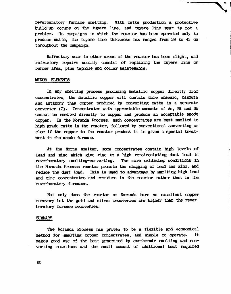
reverberatory furnace smelting. With matte production a protective build-up occurs on the tuyere line, and tuyere line wear i s not a problem. In campaigns in which the reactor has been operated only to produce matte, the tuyere line thickness has ranged from 38 to 43 cm throughout the campaign.
Refractory wear in other areas of the reactor has been slight, and refractory repairs usually consist of replacing the tuyere line or burner area, plus taphole and collar maintenance.
MINOR ELEMENTS
In any smelting process producing metallic copper directly from concentrates, the metallic copper w i l l contain more arsenic, bismuth and antimony than copper produced by converting matte in a separate converter (7). Concentrates with appreciable amounts of As, BL and Sb cannot be smelted directly to copper and produce an acceptable anode copper. In the Noranda Process, such concentrates are best smelted to high grade matte in the reactor, followed by conventional converting or else i f the copper i s the reactor product i t i s given a special treatment in the anode furnace.
At the Horne smelter, some concentrates contain high levels of lead and zinc which give rise to a high re-circulating dust load in reverberatory smelting-converting. The more oxidizing conditions in the Noranda Process reactor promote the slagging of lead and zinc, and reduce the dust load. This i s used to advantage by smelting high lead and zinc concentrates and residues in the reactor rather than in the reverberatory furnaces.
Not only does the reactor at Noranda have an excellent copper recovery but the gold and silver recoveries are higher than the reverberatory furnace recoveries.
SUMMARY
The Noranda Process has proven to be a flexible and economical method for smelting copper concentrates, and simple to operate. It makes good use of the heat generated by exothermic smelting and converting reactions and the small amount of additional heat required
60
I
can be supplied in a variety of ways using gaseous, liquid or solid fuels. The process i s ideally suited to the use of oxygen enrichment which gives both higher throughputs and lower fuel consumptions, and increases the strength of S02 in the off-gas. No special blending of the copper concentrate feed i s required and wet concentrate can be used directly. Coarse secondary material can be fed to the reactor, and high magnetite reverts which would upset the operation of other types of furnace can be consumed with ease. The Noranda Process has a high inherent stability due to the large mass of matte in the reactor which acts as a buffer against temperature changes and swings in the copper content of the charge. The operation and behaviour of the Noranda process are more predictable than conventional smelting processes, and i t has been found that acceptable operation can be achieved by personnel with limited smelting experience.
Table 8 shows the projections for a reactor smelting a 25% Cu chalcopyrite concentrate in a single reactor.
REFERENCES
(1) McKerrow, G.C., Themelis, N.J., Tarassoff, P., and I k l l e t t , G.D., The Noranda Process, Journal of Metals, Vol. 24, No. 4, April, 1972, pp 25-32.
(2) Themelis, N.J., and McKerrow, G.C, Production of Copper by the Noranda Process, in Advances in Extractive Metallurgy and Refining (ed. M.J. Jones), The Institution of Mining and Metallurgy, London, 1972, p 3.
(3) McKerrow, G.C., Hallett, G.D., and larassoff, P., Oxygen in the Noranda Process, in The Future of Copper Pyrometallurgy (ed. C. Diaz), the Chilean Institute of Mining Engineers, Santiago, Chile, 1974, p 121.
(4) Mills, L.A., Hallett, G.D., and Newman, C.J., Design and Operation of the Noranda Process Continuous Smelter, in Extractive Metal lurgy of Copper (ed. J.C. Yannopoulos and J.C. Agarwal), the Metallurgical Society of AIME, New York, N.Y., 1976, p 458.
61

(5) Godbehere, P.W., and Brooks, B.W., Milling of Copper Slags from the Noranda Continuous Snelting Process, Paper presented at the 106th ABIE Annual Meeting, Atlanta, Georgia, March 6-10, 1977.
(6) Bailey, J.B.W., Beck, R.R., Hallett, G.D., Washburn, C., and Weddick, A. J., Oxygen Snelting in the Noranda Process, Paper presented at the 104th AIME Annual ifeeting, New York, N.Y., February 16-20, 1975.
(7) Mackey, P.J., McKerrow, G.C, and Tarassof f, P., Minor Elements in the Noranda Process, Paper presented at 104th AIME Annual Meeting, New York, N.Y., February 16-20, 1975.
(8) Dayton, S., Utah Copper and the $280 Million Investment in Clean Air, Engineering and Mining Journal, April, 1979
(9) Bailey, J.B.W., and Storey, A.G., The Noranda Process After Six Years' Operation, paper presented at the 18th Annual CIM Conference of Ifetallurgists, Sudbury, Ontario, August 19-23, 1979.
(10) Bailey, J.B.W., and Dutton, W.A., Computer Control of the Noranda Continuous Smelting Process, paper presented at the 107th AIME Annual Meeting, Denver, Colorado, February 26-March 2, 1978.
(11) Bailey, J.B.W., and Ealfour, G.C, Refractory Practice for the Noranda Process, paper presented at the 109th AIME Annual Meeting, Las Vegas, Nevada, February 24-28, 1980.
62
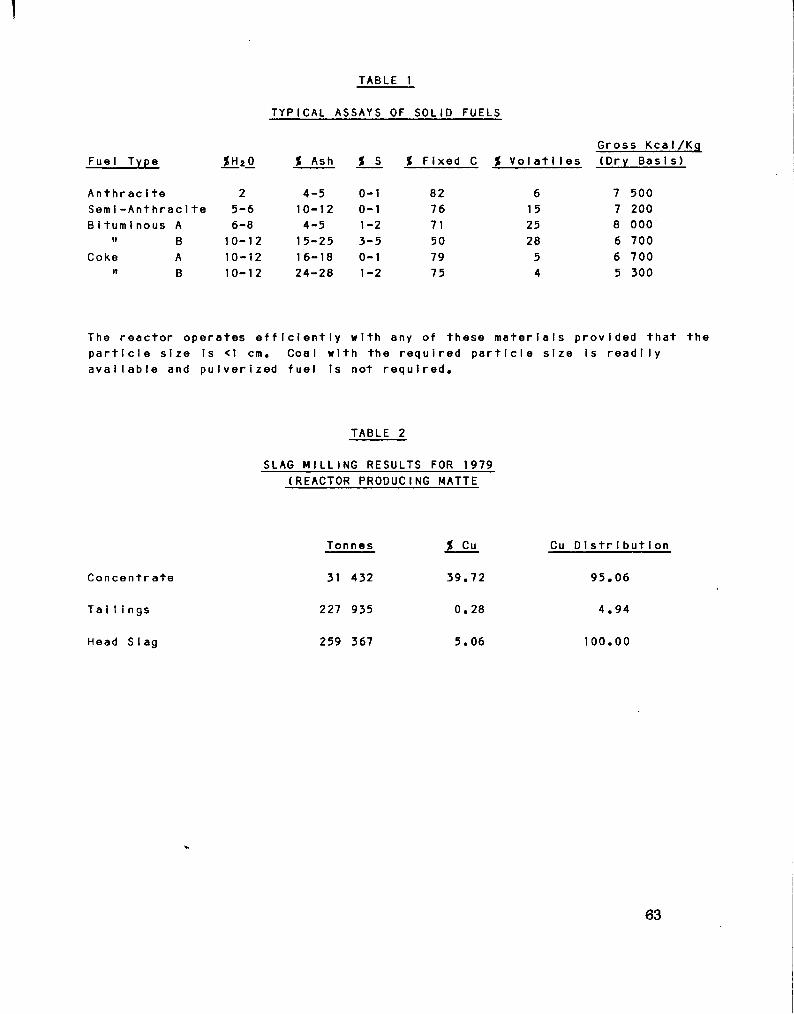
TABLE 1
TYPICAL ASSAYS OF SOLID FUELS
Fuel Type i_H2_o % Ash % s % Fixed C % Vol a t 11es Gross Kcal/Kg (Dry B a s i s )
Anthrac i te 2 4-5 0-1 82 6 7 500 Sem i - A n t h r a c 1 t e 5-6 10-12 0-1 76 15 7 200 B i turn i nous A 6-8 4-5 1-2 71 25 8 000
» B 10-12 15-25 3-5 50 28 6 700 Coke A 10-12 1 6-18 0-1 79 5 6 700
» B 10-12 24-28 1-2 75 4 5 300
The r e a c t o r operates e f f i c i e n t l y with any of these m a t e r i a l s provided t h a t the p a r t i c l e s i z e is <1 cm. Coal with the r e q u i r e d p a r t i c l e s i z e i s r e a d i l y a v a i l a b l e and p u l v e r i z e d f u e l is not r e q u i r e d .
TABLE 2
SLAG MILLING RESULTS FOR 1979 (REACTOR PRODUCING MATTE
Co n c e n t r a t e
T a i l i n g s
Head SIag
Tonnes
31 432
227 935
259 367
% Cu
39.72
0.28
5.06
Cu D i s t r i b u t i o n
95.06
4.94
100.00
63

TABLE 3
MANPOWER REQUIREMENTS
1 Genera I Foreman
4 S h i f t Crews c o n s i s t i n g o f : 1 S h i f t Foreman
1 No. 1 Operator
1 No. 2 Operator
1 Copper/Matte Tapper
1 SIag Tapper
1 Loader Operator
1 Feeder
1 Puncher 1 Dustman
1 Labourer
1 SIag Coo Ii ng Area Operator
- S u p e r v i s e s r e p a i r work and shi f t .
- S u p e r v i s e s o p e r a t i o n on shI f t .
- A d j u s t s r e a c t o r c o n d i t i o n s , keeps r e c o r d s .
- Takes bath depths, c l e a n s mouth and e v a p o r a t i v e coo I e r .
- Taps and d e l i v e r s copper/matte to the converter/anode f u r n a c e .
- Taps s l a g and takes i t t o coo l i n g a r ea.
- Sends c o n c e n t r a t e from s t o r a g e b u i l d i n g to r e a c t o r b i n s .
- Operates feed system from bins to r e a c t o r .
- Operates Gaspe puncher. - Operates p r e c i p i t a t o r -
pumps du s t . - Receives c o n c e n t r a t e s t o
b i n s . - Cools and breaks s l a g .
64

TABLE 4
RESULTS OF PERIOD ON COPPER PRODUCTION WITH AIR
Dry Compos i t i on (dry b a s i s ) , i 1 NPUT Tonnes H 20, % Cu Fe S I 0 2 S Pb Zn Fe 3 On
Copper c o n c e n t r a t e 2 681 9.0 23.5 29. 0 3 .0 33.0 3.2 3.8 Purchased r e v e r t s 3 005 5.0 29.5 22. 9 1 6 .2 13.0 0.1 0.4 22.5 Slag c o n c e n t r a t e 1 1 13 10.8 40.6 19. 6 15 .0 8.9 1 .3 2.1 -F 1 ux 440 4.0 0. 1 4. 5 66 .8 - - - -P r e c i p i t a t o r dust 281 - 1 1 .9 4. 0 2 .0 13.1 19.4 13.4 -OUTPUT
Copper 1 492 - 96.4 0. 2 _ 2.0 0.4 _ -S 1 ag 4 513 - 11.0 37. 5 22 .7 2.2 2.1 3.0 -E v a p o r a t i v e c o o l e r d u st 79 - 45.0 9. 5 5 .9 12.8 3.3 2.3 -P r e c i p i t a t o r dust 28 1 - 1 1.9 4. 0 2 .0 13. 1 19.4 13.4 -PRODUCTION DATA
Instantaneous s m e l t i n g r a t e , tonnes/day c o n c e n t r a t e plus purchased r e v e r t s 960 Average blowing r a t e , Nm'/s 13.83 Tonnage oxygen, tonnes/day 0 Oxygen content of tu y e r e b l a s t , % 21 Average f u e l r a t e , 10 s k c a l / t o n n e of copper c o n c e n t r a t e plus purchased r e v e r t 1.33 Feed-end burner f i r i n g r a t e , 10* kcal/h38 S o l i d f u e l r a t e (5.8 x 10* k c a l / t o n n e ) , tonnes/h 1.66

TABLE 5
RESULTS OF PERIOD ON COPPER PRODUCTION WITH OXYGEN ENRICHMENT
Dry Compos 111 on (dry b a s i s ) INPUT Tonnes H 20, % Cu Fe S i 0 2 S Pb Zn
Copper c o n c e n t r a t e and p r e c I p I t a t e 4 108 7.7 28.5 27.1 4.7 30.0 1 . 1 4.6
S1ag c o n c e n t r a t e 623 8.4 39.2 19.9 15.3 11.1 0.1 2.9 Flux 567 9.2 - 2. 1 78.2 - - -P r e c i p i t a t o r dust 210 - 22.8 6.8 3.2 1 1 .7 5.0 16.9
OUTPUT
Copper 1 104 - 97.5 0.4 - 2.0 - -Slag 3 392 - 9.6 36.7 25.0 1.2 1.2 5.7 E v a p o r a t i v e c o o l e r dust 33 - 37.1 19.4 11 .2 6.2 1 .0 4.0 P r e c i p i t a t o r dust 229 - 22.7 6.8 3.2 11.8 4.0 17.1
PRODUCTION DATA
Instantaneous s m e l t i n g r a t e , tonnes/day 1 560 Average blowing r a t e , Nm'/s 16.61 Tonnage oxygen, tonnes/day 325 Oxygen content of tuyere b l a s t , % 30 Average f u e l r a t e , 10 6 kcal tonne of copper c o n c e n t r a t e 0.17 Feed-end burner f i r i n g r a t e , 10* k c a l / h 9.1 Sol id f u e l r a t e 0
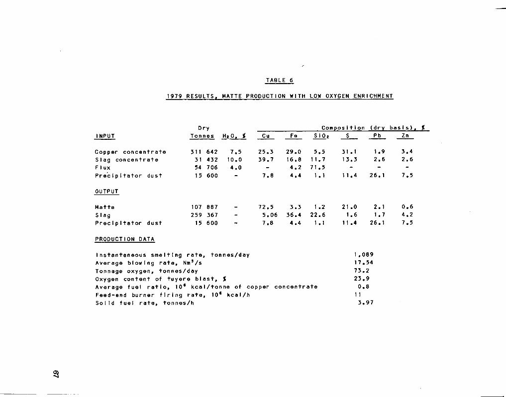
TABLE 6
1979 RESULTS. MATTE PRODUCTION WITH LOW OXYGEN ENRICHMENT
Dry Composition (dry b a s i s ) , % 1 NPUT Ton nes H*0, % Cu Fe S I 0 2 S Pb Zn
Copper c o n c e n t r a t e 311 642 7.5 25.3 29.0 5.5 31.1 1 .9 3.4 Slag c o n c e n t r a t e 31 432 10.0 39.7 16.8 11.7 13.3 2.6 2.6 F 1 ux 54 706 4.0 - 4.2 71.5 - - -P r e c i p i t a t o r dust 1 5 600 - 7.8 4.4 1 . 1 1 1.4 26. 1 7.5
OUTPUT
Matte 107 887 _ 72.5 3.3 1 .2 21 .0 2.1 0.6 S 1 ag 259 367 - 5.06 36.4 22.6 1.6 1.7 4.2 P r e c i p i t a t o r dust 15 600 - 7.8 4.4 1.1 1 1 .4 26.1 7.5
PRODUCTION DATA
Instantaneous s m e l t i n g r a t e , tonnes/day Average blowing r a t e , Nm'/s Tonnage oxygen, tonnes/day Oxygen content of tu y e r e b l a s t , % Average f u e l r a t i o , 10* k c a l / t o n n e of copper Feed-end burner f i r i n g r a t e , 10* k c a l / h S o l i d f u e l r a t e , tonnes/h
c o n c e n t r a t e
1 ,089 17.54 73.2 23.9 0.8
1 1 3.97

TABLE 7
REACTOR REFRACTORY CONSUMPTION
AVERAGE REFRACTORY CONSUMPTION
kg/tonne of c o n c e n t r a t e
Copper P r o d u c t i o n Matte P r o d u c t i o n C o n v e n t i o n a l Reactor Reactor Sme I t e r
Smelting Vessel C o n v e r t e r Anode Furnace 0.05
1 .55 0.55 0.75 0.05
1 .35 0.75 0.05
TOTAL 1 .60 1 .35 2.15
68
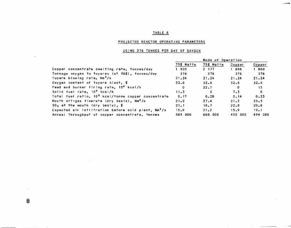
TABLE 8
PROJECTED REACTOR OPERATING PARAMETERS
USING 376 TONNES PER DAY OF OXYGEN
Mode of Op e r a t i o n
Copper c o n c e n t r a t e s m e l t i n g r a t e , tonnes/day Tonnage oxygen to t u y e r e s (at 96$), tonnes/day Tuyere blowing rate> Nms/s Oxygen content of tuy e r e b l a s t , % Feed end burner f i r i n g r a t e , 10 6 k c a l / h S o l i d f u e l r a t e , 10* k c a l / h T o t a l f u e l r a t i o , 10* k c a l / t o n n e copper c o n c e n t r a t e Mouth o f f - g a s f l o w r a t e (dry b a s i s ) , Nm'/s SOa at the mouth (dry b a s i s ) , % Expected a i r i n f i l t r a t i o n b e f o r e a c i d p l a n t , Nms/s Annual throughput of copper c o n c e n t r a t e , tonnes
75$ Matte 1 905
376 21 .24 32.6
0 1 1.3 0.17
21.2 21 . 1 15.9 585 000
75$ Matte 2 177
376 21 .24 32.6 22.7
0 0.28
27.4 18.7 21 .2 668 000
Copper 1 696
376 21 .24 32.6
0 7.3 0.14
21.2 22.8 15.9 450 000
Copper 1 860
376 21 .24 32.6
15 0
0.23 25.5 20.8 19.1 494 000
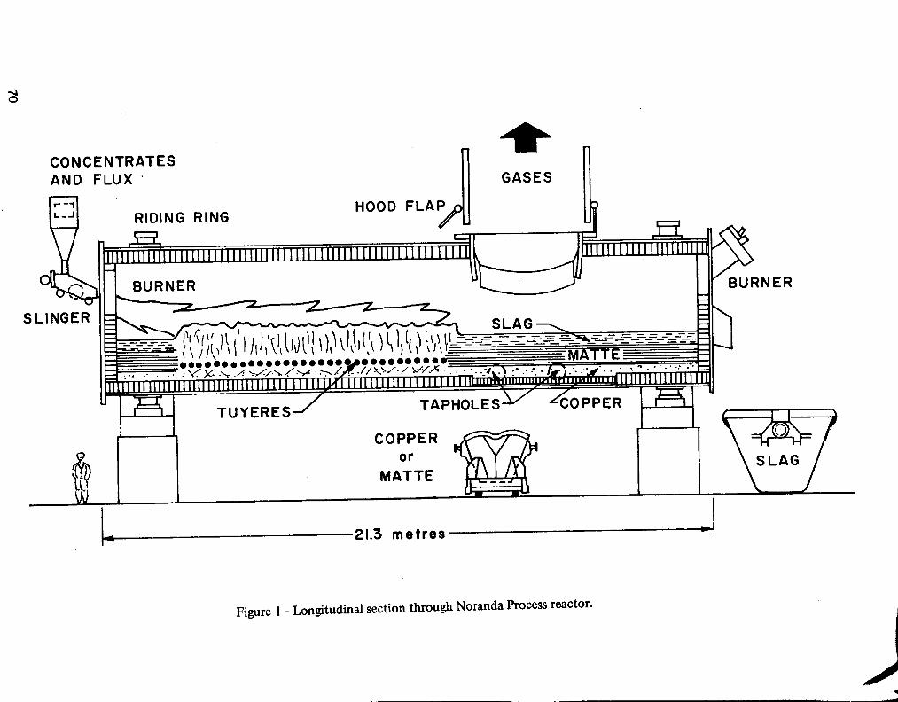
3
CONCENTRATES AND FLUX
SLINGER
RIDING RING _5L
HOOD F L A ^ P
GASES
i n 111111M111 i 111111111111111111111111111 l_LLLLLLL,
BURNER fc
SLAG
21.3 metres
Figure 1 - Longitudinal section through Noranda Process reactor.

TUYERES
HOOD FLAPS
MATTE
BLOWING POSITION
DRIVE PISTON
Figure 2 - Sections through reactor in blowing and standby positions.

GASES TO STACK PRECIPITATOR
2 EVAPORATIVE
COOLER
\ /
DUST SLAG CONC.
COPPER CONC.
DRUM MIXER
AIR BLOWER COPPER OR MATTE
TO CONVERTER OR ANODE FURNACE
SLAG MILLING
SLAG CONC.
SLAG TAILINGS
Figure 3 - Flowsheet for Noranda Process reactor.
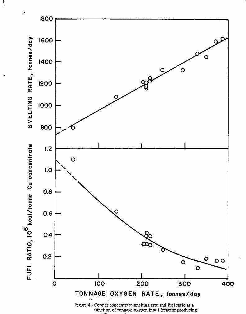
Figure 4 - Copper concentrate smelting rate and fuel ratio as a function of tonnage oxygen input (reactor producing

V

SECTION IV
RECENT OPERATION OF MITSUBISHI CONTINUOUS OOragft SteflER
AT NAOSHIMA.
BY T. SUZUKI
Recent Operation of Mitsubishi Continuous
Copper Smelter at Naoshima
Dr. Takashi Suzuki Director and General Manager
Metallurgy Department Mitsubishi fetal Corporation
Paper to be presented at British Columbia Copper Smelting and Refining Technologies Seminar, Organized by the B.C. Ministry of Energy, Mines and Petroleum Resources, November 5 and 6, 1980, Vancouver, B.C.
76
ABSTRACT
Mitsubishi Metal Corporation has been operating Mitsubishi Continuous Copper Smelter at Jfe.oshima for six year since 1974. During the past period, various kinds of improvement works have been directed toward attaining stable operations and lower operation cost. F i r s t of these was modification of furnace shape from oval to circular. Second was the addition of water-cooled copper jackets to the side wall of the furnaces. Third was changing the roof burners to short flame type burners, which are now installed at the side wall. Fourth was mixing of coal with copper concentrate to replace part of the fuel o i l . F i f t h , was higher oxygen enrichment of lance blast. As a result the furnace campaign was extended to around one and one half years, and the monthly production of copper was increased by 10 to 20% over the rated capacity. The paper discusses respective modifications, and then shows a model smelter plan with maximum u t i l i z a t i o n of oxygen.
77

INTRODUCTION
Mitsubishi Continuous Copper Smelting Converting Process (Mitsubishi Process) i s one of the most advanced copper snelting technologies in that i t i s an integrated continuous process from smelting stage through converting stage (1-2). To develop the process Mitsubishi Metal Corporation (MMC) spent five years operating a pilot and a serai-canmercial plant, having a capacity of 4 000 tonnes of copper per month at i t s Naoshima smelter. Since then various improvements and modifications were performed, and now the campaign length exceeds one year and monthly copper production exceeds the designed capacity by 10-20%.
Many of the advantageous features of the Mitsubishi Process are attributable to i t s continous and integrated nature of operation. For example, one of the most remarkable advantages i s that the Mitsubishi Process can easily ccrapley with most stringent regulations on sulfur oxides emission. Fugitive gases are minimized and can easily be captured, i f there i s any, because molten metallurgical products are transfered through launders. Furnaces and associated f a c i l i t i e s can be designed compact thereby decreasing capital expenditure. At the same time operation i s very much simplified because such jobs are eliminated as matte tapping, ladle transportation, and converter slag skimming, which are indispensable in conventional batchwise operations.
Since the new "Clean Air Act" was enacted in 1975, a l l the primary smelters in North America were obliged to make provisions to recover more than 90% of sulfur input, and i t i s expected that the situation would become more stringent in the future. With such background, the Mitsubishi Process could provide one of the best solutions to comply with the regulation.
After careful f e a s i b i l i t y studies, Texasgulf Canada Ltd., determined in 1975 to apply the Mitsubishi Process for i t s new copper smelter in Timmins, Ontario, and started detail engineering works immediately followed ty construction (3). Trie reasons for their choice of the process are that:
(1) It i s proved in commercial scale at Naoshima Smelter,
(2) It i s not labour intensive,
78

(3) A converter aisle i s eliminated as molten matal lurgical products are transferred through launders,
(4) The capital cost i s competitive to the conventional process,
(5) SO2 recovery i s higji and emission i s low.
The new copper sue Iter was originally scheduled to be completed in 1978. However, the completion was delayed by two years due to unfavourable copper market conditions. It i s expected to start-up in April, 1981.
Taking advantage of the opportunity to attend the Br i t i s h Columbia Copper Smelting and Refining Technologies Seminar, the latest operation data of the continuous plant at Naoshima w i l l be introduced and various improvements and test works performed during the past six years w i l l be discussed.
PROCESS DESCRIPTION
The detailed instructions on the process features of the Mitsubishi Process and the Ifeoshima plant were published on various occasions, but the essential parts are summarized below for better understanding.
The Mitsubishi Continuous Copper Snelting Process i s a process to produce bli s t e r copper continuously from copper-bearing raw materials by a series of furnaces, e.g., smelting, slag cleaning and converting furnaces, which are linked together. A schematic flowsheet i s shown in Figure 1. The designed capacity of the Jfeoshima Plant i s 4 000 tonnes of copper per month.
SMELTING FURNACE (S-FURNACE)
The smelting furnace i s 8.25 m in diameter, 3.3 m in height, both inside bricks, and 1.1 m in bath depth, lined with direct bonded chrome-magnesite bricks and fused cast chrome-magnesite bricks at severe wear areas. It i s provided with six or seven lances which perpendicularly penetrate the furnace roof. The concentrate i s dried
79
and continuously delivered at a constant feed rate, e.g., at 25-27 tonnes per hour, and at the same time, s i l i c a and limestone flux, return O-slag and dusts are mixed at an appropriate ratio. The mixed solid charge i s fed pneumatically through five feeding hoppers into inner tubes of the lances. Oxygen enriched lance blast a i r i s introduced through outer tubes of the lances via lance heads. lance blast and solid charge are mixed at the lower part of the lances and injected into the molten bath with high velocity. The oxygen and a i r supply i s adjusted to maintain the matte grade at 65% copper. As matte and slag produced are taken out by overflow, slag layer in the furnace i s very thin, and the molten bath i s composed mainly of matte which i s rich in unoxidized sulfur and iron, and highly reactive to oxygen. As a result, the smelting reactions proceed rapidly, and the oxygen u t i l i z a tion efficiency of the lance blast i s very high although the lances are not submerged into the bath. Recently some amount of pulverized coal i s mixed with concentrate so as to replace a part of fuel o i l which i s burned through burners installed at the sidewall. Furnace temperature i s controlled by adjusting the fuel o i l rate. Combustion air i s not preheated.
SLAG CLEANING FURNACE
The products of the smelting furnace, e.g., slag and matte, overflow through a common overflow hole, and are transferred to the slag cleaning furnace via a heated launder. The slag cleaning furnace i s an el e c t r i c furnace with 4.2 m in width, 7.0 m in length and 2.2 m in height inside bricks, provided with three prebaked graphite electrodes
4 i n row. The transformer capacity i s 1 200 KVA. The slag i s separated from matte, cleaned to 0.5-0.6% copper while being retained about one hour, then caused to overflow at an equivalent rate with that of transfer from the smelting furnace. The slag i s finally water-granulated and discarded. The matte i s siphoned out and transferred to the converting furnace through a heated launder.
CONVERTING FURNACE (OFURNACE)
The converting furnace i s 6.65 m in diameter, and 2.9 m in height, both inside bricks, and 0.75 m in bath depth. Various features of the converting furnace are essentially the same as those of the smelting furnace except the dimension and tapholes arrangement. In the convert-
80

ing furnace, matte i s continuously converted to bl i s t e r copper by blowing a i r into tt\e molten bath through lances. The amount of a i r i s adjusted to oxidize not only a l l the iron and sulfur, but also a part of copper in the matte to copper oxide. A small amount of limestone i s added through lances, thus forming a special converter slag comprising CuaOCaO-Fe SOH ternary system. CaO i n the converter slag i s controlled at about 15%, and CU at 15 to 20%. Under these operating conditions, the sulfur content of the blister copper can be reduced to 0.1-0.5%, which i s far lower than saturation. Blister copper i s siphoned out, stored temporarily in a holding furnace then delivered to the anode furnace by a ladle car, refined and cast into anodes. Converter slag i s tapped through a slag hole, water-granulated, dried and returned to the smelting furnace.
A l l the process supplies are monitored and controlled by the computer system. Molten products are sampled every hour and analysed automatically. The results are fed back to the control system to adjust feed rates of process supplies (4).
Gases from the smelting and converting furnaces are cooled to about 350°C through respective boilers. Respective draft control dampers for the smelting and converting furnaces are provided at the outlet of the boilers. Recovered steam i s sent to a recently constructed power plant. The gases are then introduced into Cbttrell precipitators, and the cleaned gas from the Cbttrells i s sent to the acid plants. The 902 concentration of the combined gas i s 10-11%. Major features of the furnaces are summarized in Table 1, and typical recent operation data in Table 2 and 3.
The Mitsubishi process has various advantages over the conventional processes as summarized below:
(1) It i s easy to operate: As both smelting and converting processes are integrated and continuous, various jobs, indispensable with conventional operations, such as tapping of matte and slag, ladle transferring of matte and converter slag, converter slag skimming, are eliminated. The process i s highly mechanized and automated. Therefore operation i s simplified, resulting in substantial manpower saving. At the same time, in-plant inventory of copper i s reduced.
81

(2) The furnaces can be designed compactly: The smelting rate, e.g., throughput per unit volume of the furnaces, i s very high as the charge mixture i s fed through lances and injected into molten bath, where substantial heat of reactions are evolved. Therefore, the design of the furnaces and smelter building can be compact.
(3) Fuel consumption i s low: High grade matte can be obtained at the smelting furnace while keeping copper loss of slag at an economically acceptable level. The slag can be discarded without further processing. Thus, c a l o r i f i c value of copper concentrates can be u t i l i z e d at maximum extent. With u t i l i z a t i o n of tonnage oxygen, fuel requirement can greatly be reduced.
(4) Gas trains can be designed compactly: Off-gas volume can be minimized especially when maximum amount of tonnage oxygen i s used. Therefore, the design of the gas trains can be compact.
(5) It i s easy to comply with most stringent emission regulations: A l l three main furnaces are of a stationary type, which are free from any complicated mechanical structures, such as furnace t i l t ing f a c i l i t i e s , tight f i t t i n g hood driving mechanisms, and tuyere punching mechanism. As molten metallurgical products are transferred through covered launders, sulfur dioxide and particulates emissions are minimized and can easily be captured, i f any.
As a whole, the Mitsubishi Process requires smaller capital expenditure, operation cost and manpower.
MODIFICATION AM) IMPROVEMENTS
Many of the modifications during the past six years were briefly discussed in a previous paper; (5)
82

The furnace shape was modified from oval to circular.
V/ater-cooled copper blocks were added to cool the sidewalls effecti v e l y , and bottom cooling system was also modified.
Hoof burners were changed with short flame type burners which were installed at side walls.
Pulverized coal was mixed to copper concentrates, thereby improving c a l o r i f i c value of them and replacing part of fuel o i l burnt through burners.
Highly oxygen-enriched lance blast a i r was tested, which could reduce fuel requirement and off-gas volume substantially, or could allow higher throughput within a limited size of the furnace.
With those modifications in the f a c i l i t i e s and improvements in operation, one year furnace campaign l i f e has been established for both 9-and OFurnaces, and monthly production of copper exceeded by 10 to 20% over the designed capacity. As a result, Mitsubishi Metal Corporation decided to achieve the production only with the main furnaces and the stand-by furnaces were demolished.
In Mitsibushi Metal Corporation's case, stand-by S-and-C-Furnaces were installed with two main purposes:
(1) to maintain steady copper production during boiler inspection period which i s associated with main furnace line; and
(2) to allow shut-down of main furnace line that i s long enough to perform various possible modifications which might be required especially, for the f i r s t commercial plant of a new process.
Monthly anode productions in the latest campaign, which i s s t i l l continuing, are sirmarized in Tkble 4. This campaign w i l l be continued further after a temporary shut down for boiler inspection at the end of November.
83

MODIFICATION OF FURNACE DESIGN
In the Mitsubishi Process, the furnace design i s one of the most important items to be studied carefully. Turbulence given to the molten bath i n the furnaces i s far larger than that of the other smelting furnaces, such as reverberatory or electric furnaces, due to the lancing operation. In the original design, the furnace shape was oval shaped and the shell was divided into several parts connected by bolt-nuts with springs. On the other hand in the modified design, the furnace shape i s circular and the shell i s a welded and mono-block structure (6-7).
With the oval shape, the lance could be located in line parallel with long axis, thereby the accessibility to the lances was assured. However, expansion of the brick works was not homogeneous i n oval shape furnaces, and sometimes abnormal expansion was observed at the shell partition area. During the furnace repair after a one year campaign, the slag line and part of the brick works on the sidewalls near the burners were repaired. The hearth brick was normally sound, because i t was not subjected to corrosion by either matte or b l i s t e r copper. Nevertheless, the accumulated abnormal expansion made i t inevitable to reline the bottom bricks even i f the individual bricks were sound. Contrary to this, with a circular furnace design thermal expansion can be almost homogeneous and abnormal expansion, as observed in the oval shape, w i l l be avoided.
With larger diameter lances, the number of lances i s reduced to half of the original number as shown in Table 5. Even at the smelter with larger capacity, the number of lances could be minimized by applying higher oxygen enrichment for lance blasts. Thus, lance arrangement i s not any more a limiting factor for taking a circular furnace design.
At the same time with modification of furnace shape, the cooling system was also modified. With the turbulent flow of the molten bath, the slag line of both smelting and the converting furnaces are subjected to severe wearing conditions. In the original design, water-cooled spray boxes were provided at the slag line to cool and prevent wear of the lining in these areas. The system i t s e l f worked well. However, sidewall above the bath level also suffered from wear, presumably due to splashes of molten slag and matte and direct exposure to high-temperature burner flames. For this reason, two or three layers
84

of water-cooled copper blocks were added in the sidewall near burners i n the modified design. The same provision was also made on the furnace roofs.
Bottom cooling was also intensified. Originally the furnace bottom was lined with two brick layers composed of 350 nm thick fused-cast bricks and 230 nm thick chemical bonded magnesite-chrome bricks on tamped periclase at the very bottom. When 180 000 tonnes of solid charge was injected after the commercial plant was put into operation in March, 1974, the arched bottom structure of the smelting furnace was partly damaged. Then the bath depth was increased to 1 090 nm from the original 800 ran. At the same time, the bottom brick was reduced to single layer and the bottom ai r cooling was intensified. With this modification, the bottom bricks were cooled effectively and permeation of matte and slag was minimized. Figure 2 and 3 show modified S and O furnaces.
LANCE BLOWING
Lancing techniques to feed solid materials and oxygen-enriched a i r into the molten bath i s one of the unique features of the Mitsubishi Process. Figure 4 shows the feeding system. Solid charges, such as dry copper concentrates, s i l i c a and limestone fluxes and reverts are proportioned onto a common conveyor line, which conveys them up to the top of the smelter building. Solid charges are distributed into five feeding hoppers, out of which they are delivered pneumatically and conveying tubes are regulated as low as possible to minimize erosion of the pipeline. To the lances, oxygen-enriched a i r i s supplied separately. Solid charge and oxygen-enriched a i r are mixed together at the lower part of the lances and injected into the molten bath at a high velocity. Solid particles are entrained in the bath and melted rapidly . Lance blast oxidizes the iron and sulfur and maintains the matte grade at 65% copper.
The lances are installed vertically through the roof of the furnace and the tips of the lances are positioned right above the bath surface. The original two and one-half-inch lances were recently replaced with three inch lances and *the number of lances was reduced as shown in Tkble 5. Tkble 6 shows a typical operating condition of the lance.
85

At the end of the f i r s t one year campaign, i t was found that the smelting furnace bottom was partly damaged at the area just beneath the lances as mentioned previously. It was estimated that the damage was caused by the jet of air - s o l i d charge mixture based on the following observations:
(1) There was no damage in the converting furnace, where the amount of sol i d charge was far smaller and the density of the molten copper bath was far larger than the matte bath in the smelting furnace.
(2) The damage was limited only in small area just beneath the lances.
By analyzing the effect of lancing on the bottom bricks u t i l i z i n g the model equation developed in connection with the lancing practices i n steel industry, the bath depth in the smelting furnace was increased by about 300 ran. Further, the hearth structure was modified when the furnace shape was changed. As described previously, the bottom brick lining was changed to one layer and the area beneath the lances was lined with f used-cast magnesite-chrome bricks. The furnace bottom i s now air-cooled from outside and permeation of the matte into the bricks i s prevented. It i s known that with permeation of matte, the mechanical strength of the bricks decreases remarkably.
Further study was performed at the Research Center to analyze behaviour of the gas-solid mixture jet in the bath and an experimental equation was developed. It was found that the lance height and solid feed rate have the largest effect on the penetration depth of the particles in the bath (8). In the operation, instantaneous feed rate at an individual lance was decreased by decreasing the flow rate of the conveying air. lance height was checked every shift by inspecting inside the furnaces visually to check the conditions of the actual lances.
MODIFICATION OF THE BURNER
As mentioned earlier, the sidewall near the burner was one of the severe wear areas. The original burner was installed at the roof with
86

]
an angle so that the flame would impinge to the center of the bath. The burner i t s e l f was made with mild steel a i r duct and o i l atomizing gun in i t . In the actual operation, there was a. tendency that splashes of molten slag and matte entered inside the burner and accretions were formed, especially at the mouth. As a result, the flame became unstable and i t was estimated that the sidewall or roof near the burner might be exposed directly to the hot flame in such a condition. The f i r s t measure taken to reduce refractory wear was the application of copper jackets, as mentioned previously.
As the second and more important measure, modification of the burner i t s e l f was tested. The burner tested has a combustion chamber as shown in Figure 5. The corabustion chamber i s lined with high alumina castable material and cooled with combustion air from outside. The o i l i s burned in the chamber and the hot gas produced i s discharged through the mouth with high velocity. As the mouth i s always exposed to high temperature combustion gas, the splashes that enter the mouth are expected to flow down ait of the mouth. At f i r s t one of the old long flame type burners was replaced with a short flame burner, which was installed at the sidewall instead of the roof. Then the refractory wear around the new burner was remarkably reduced compared to the other burner areas.
In August, 1978, two of the old burners were replaced and in September, 1979, a l l the burners were replaced. Figure 5 shows the modified burner arrangement. With this modification, refractory wear was remarkably reduced as being demonstrated by the pictures of the brick works. Figure 6 shows brick condition around the slag-matte outlet after a one year campaign with the old type burner. Swelled parts are rows of copper jackets, and hollow parts are worn bricks. Figure 7 shows brick condition at the same area as Figure 6 after a one year campaign with the new type burners. The surface i s f l a t , which means that brick wear was very small even after one year operation. With such improvements the repair became no longer necessary for these areas.
UTILIZATION OF COAL
The extraordinary increase in o i l price since 1974 gave enormous economical impacts on the smelters. A preliminary test to replace part
87

of the o i l with coal was started at the continuous smelter to relieve the impact.
In the normal mode of coal combustion, coal i s finely ground and burned with a coal burner. As the Naoshima Smelter i s designed to u t i l i z e only the liquid fuel, none of the f a c i l i t i e s have been provided to prepare and burn fine-ground coal. Thus, i t was intended to burn purchased pulverized coal without further grinding. At f i r s t , coal was fed into the furnace through a drop chute. However, the combustion rate was limited. Then, i t was considered to feed pulverized coal into a mixture with copper concentrates through lances fcy bedding the wet coal with concentrates and drying with a concentrate dryer.
To check the susceptibility of coal for f i r i n g in the dryer, the igniting temperature was measured for coal as well as for various copper concentrates. The igniting temperature for chalcopyrite type copper concentrates was 200°-250°C, 180°C when pyrrhotite was contained, 150°C for pulverized coal. However, the igniting temperature of the mixed concentrates containing 2% pulverized coal was 226°C which was higher than that of coal i t s e l f . Encouraged with these measured data, the actual test was performed.
In the f i r s t stage, 2-3 wt % of coal was added to concentrates. During treatment of the coal containing concentrates, fuel o i l consumption could be decreased by the amount c a l o r i f i c a l l y equivalent to coal. About 30-40% of fuel o i l consumption of the snelting furnace was thus replaced with coal. By the temporary test i t was found that even up to 70% of fuel o i l consumption could be replaced with coal i f enough oxidation air could be supplied through lances. Table 7 shows typical operation data with and without coal u t i l i z a t i o n . C a l o r i f i c value was 10 000 Kcal per kg for fuel o i l and 7 100-7 300 Kcal per kg for coal. Then, the calculated equivalent fuel rate for an oil-coal dual system was 1,300 1/h, which was slightly smaller than 1,370 1/h in the case when only o i l was used.
By feeding coal through lances, the refractory wear i s expected to decrease, because of the reduced fuel rate at the burners and the smaller effect of radiation of the flame on the wall. Coal w i l l burn in the molten bath or at the surface of i t . Ttie heat evolved may be effectively transferred to the molten bath without making hot flame.
88
It was thought that the addition of coal to concentrates, among the various improvements, might have given a large contribution to improve monthly copper production. Major advantages are as follows:
(1) The bath temperature was maintained at slightly higher, by 20°C, and the molten bath had a higher f l u i d i t y as judged fcy visual inspection. Hourly throughput was increased as a result.
(2) The slag loss of copper was reduced.
A key to such improvements can be attributed to the improvement of local heat balance in the areas where charge materials are injected into the molten bath. Combustion of coal i s expected to take place at the surface of the molten bath, then the heat evolved in this area i s increased with coal, which i s effectively transferred to the molten bath or to the solid charge. This direct heat transfer mechanism i s one of the major advantages of the Mitsubishi Process. With the high copper-low sulfur concentrates this advantage would greatly be offset i f coal i s not added. This item w i l l be discussed later.
HIGH OXYGEN ENRICHMENT OF LANCE BLAST
The lance blast for the smelting furnace of the continuous plant i s normally oxygen-enriched up to 30%-40%. U t i l i z a t i o n of tonnage oxygen in the smelting process has various advantages as follows:
(1) It decreases fuel consumption.
(2) It decreases off-gas volume and consequently the size of f a c i l i t i e s for gas treatment.
(3) It makes i t possible to smelt higher throughput within a smaller furnace.
Figure 8 shows calculated off-gas volume, fuel requirement and concentrate feed rate at different levels of oxygen enrichment. Calculations were based on the existing Naoshima plant. To confirm the calculated results, test works were performed in stages.
89

At the f i r s t stage, one lance was chosen and oxygen concentration was increased stepwise by five per cent at a time and fi n a l l y to sixty percent. This test proved that i t was free from problems such as quicker burn-out of lance and combustion of concentrates during transfer in the lance pipe.
The second stage was a f u l l scale test, in which oxygen concentration of the lance blast for a l l the S-furnace lances was increased up to about f i f t y per cent. The following were confirmed by the test:
There was no change in lance consumption.
Fuel consumption and off-gas volume were reduced. At a plant with a larger capacity, autogeneous operation could be possible.
It was easier to keep optimum bath temperature.
Concentrate feed rate could be increased proportionally to the total oxygen content of the lance blast.
Typical test data are shown in Table 8. Oxygen concentration of S-furnace lance blast was increased from 30%r-50% while concentrate feed rate was maintained unchanged. Off-gas volume was reduced almost as expected.
The range of operating conditions during high throughput tests i s shown in Figure 8. Average concentrate smelted in an operating day was 580 tonnes in normal case and 760 tonnes during the test. The smelting rate was improved to 14 tonnes per square metre of hearth per day from 11 in regular operation. The limitation for the test was the capacity of existing feeding system and oxygen supply. There was no metallurgical limitation found to increase the throughput further.
MODEL PLANT WITH 100 000 TONNES ANNUAL CAPACITY
With a l l the improvements discussed so far, the smelting operation could be now thermally autogeneous in a larger plant by applying higher oxygen enrichment for the 9-furnace lance blast.
90
The fuel requirements for a plant with 100 000 tonnes annual capacity are shown in Figure 9 at varying oxygen enrichment levels for three different cases. With normal chalcopyritic concentrate the smelting operation i s autogeneous at 60% oxygen enrichment (type A). The composition of type A concentrate i s identical with what was applied in an evaluation study of a metallurgical complex in B r i t i s h Columbia (9) except that the content of sulfur was revised to 35% from the original figure of 38%.
With the higher grade concentrate (type B), fuel requirement i s s t i l l relatively high even at a higher level of oxygen-enrichment as shown in the figure by the line B. For such a case, apparent c a l o r i f i c value of the concentrate could be increased by mixing small amounts of pulverized coal as shown with line C i n the figure. In this case the coal mixing ratio i s 3.4%. By increasing the coal ratio, the fuel o i l requirement could be reduced to zero.
Taking the autogenous point as a model case condition, a set of process calculations was made and attached to this paper as an appendix. Based on this model, energy consumption was evaluated and shown in Tkble 9. In the table, fuel consumption includes dryer for concentrates, anode furnaces, and launder heating-up. Power consumption includes electric furnace, production of tonnage oxygen, material handling, compressors and blowers including those for fugitive gas collection, excluding the acid plant.
With higher oxygen enrichment, the furnaces can be compact. The smelting rate, which i s copper production per day per unit furnace volume including roaster, smelting furnace, converters, and el e c t r i c furnace, was calculated and compared with various processes. As shown i n Tkble 10, the smelting rate i s largest for the Mitsubishi Process. With compact furnaces and gas trains, capital expenditure for the continuous plant could be reduced.
Another remarkable advantageous feature of the process i s that i t can easily comply with the most stringent S0i emission regulations. To show such a situation, the fugitive gas handling systems of various types of smelters are summarized in Tkble 11. The respective features were taken from published papers as far as possible, (10-12) or e s t i mated i f not available in a published material. Fugitive gas volume
91

to be collected vary widely depending on the type of process and also on the location of the plant (different regulation). However, i t i s obvious that the Mitsubishi Continuous Process can easily reduce emissions without applying any extensive fugitive gas collection system.
It should also be pointed out that the Mitsubishi Process can greatly save manpower requirements as shown in Table 12.
SUMMARY
During the past six years of operation, various improvements on the furnace design and operating procedure were performed. The major items are:
(1) Furnace shape was modified from oval to circular.
(2) Water-cooled copper jackets were added at the sidewall of the furnace.
(3) Roof burners were changed to short flame type burners which were installed at the sidewall.
(4) Coal was mixed with copper concentrate to replace part of fuel o i l .
As a result, the furnace campaign was extended from one to one and a half years and the monthly production of copper was increased by about 20%. It was then decided to achieve the production only with the main furnaces and demolish the stand-by furnaces.
By applying higher oxygen enrichment for S-furnace lance blast, furnaces can be designed compact and smelting can be performed therma l l y autogenous. Taking as a model case a smelter with 100 000 tonnes annual capacity, the results of the process calculation were shown. Various specific features such as smelting rate, fugitive gas collection, manpower requirements were compared with the other processes.
92

REFERENCES
(1) T. Nagano and T. Suzuki, "Commercial Operation of Mitsubishi Continuous Copper Smelting and Converting Process", in Extractive Metallurgy of Copper, Ed. J. C. Yannopoulos and J. C. Agarwel, the Metallurgical Society of AIME, New York, N.Y., 1976, pp. 439¬457.
(2) T. Nagano and T. Suzuki, "Process Development for Continuous Copper Smelting and Converting", paper presented at the 15th Annual Conference of Metallurgists, the Metallurgical Society of The Canadian Institute of Mining and Metallurgy, August 22-26, 1976, Ottawa, Canada.
(3) M. P. Ansden, R. M. Sweetin and D. G. Treilhard, "Selection and Design of Texasgulf Canada's Copper Smelter and Refinery", J . MetalIs, Vol. 30, July 1978, pp. 16-26.
(4) T. Shibasaki and Y. Tbsa, "Application of Computer Control to Mitsubishi Continuous Copper Snelting Process", ISA (Instruments Society of America) Transactions, Vol.17, No. 2, pp 93-100, 1978.
(5) T. Suzuki and M. Goto, "Recent Improvements in Mitsubishi Process Operation", paper presented at the Annual Meeting of Arizona Section, The Metallurgical Society of AIME, December 3, 1979, Tucson, Arizona, USA.
(6) M. Goto and K. Kanamori, ''Converting Furnace Operation of Mitsubishi Process", in Copper and Nickel Converters, Ed. R. E. Johnson, The Metallurgical Society of AIME, New York, N.Y., 1979.
(7) M. Goto and T. Echigoya, "Refractory Practice and Application of Water Jackets in Mitsubishi Process", Paper presented at the 109th Annual Meeting of AIME, February 1980, las Vegas, Nevada, USA.
(8) E. Kimura, "lancing Mechanism in Mitsubishi Continuous Smelting Furnace", paper presented at the Symposium of 140th Committee (Physico-Chemical Properties of Substances at Metallurgical Temperature), Japan Society for the Promotion of Science, October 31, 1979, Tokyo (Japanese).
93
(9) "Evaluation of a Metallurgical Complex in Br i t i s h Columbia", A study by Wright Engineers Ltd. and H. N. Halvorson Consultants Ltd., Iferch 1979, Province of B r i t i s h Columbia, Ministry of Economic Development.
(10) H. TJchida, N. Kikumoto and M. Hayashi, "Processing of Copper Smelting Gases at Naoshima Smelter", paper presented at the Symposium on Control of Particulate Emissions in the Primary Non-ferrous Metals Industries, Iferch 18-21, 1979, Monterey, C a l i fornia, USA, (EPA Organized).
(11) H. Kohno, K. Sugiyama and Y. Sugawawa, "Fugitive Gas Treatment at Onahama Smelter", paper to be presented at the Fourth Joint Meeting of UAH J-AIME, November 4-8, 1980, Tokyo, Japan.
(12) T. Kawakita, T. Watanabe and H. Yonei, "Emission Control at Tamano Smelter", paper presented at the F a l l Meeting of the Mining and Metallurgical Institute of Japan (MMIJ), October, 17-19, 1977, Fukuoka, Japan.
94

TABLE 1
MAJOR FEATURES OF NAOSHI MA CONTINUOUS PLANT
Design Capac i ty C o n c e n t r a t e Grade
4 000 Tonnes Cu/m 27. 5%
Furnace Design
S-Furnace D I ameter He!ght Bath Depth
Slag C l e a n i n g Furnace
Di ameter Hei ght Bath depth Transformer c a p a c i t y
8.25 n i n s i d e b r i c k s 3.31 m i ns i de br i c k s 1.09 m i n s i d e br i cks
7.00 m x 7.20 m i n s i d e b r i c k s 2.21 m x 7.20 n i n s i d e b r i c k s 1.11 m x 7.20 m i n s i d e b r i c k s 1 200 KVA
C-Furnace
D i ameter Hei ght Bath depth
6.65 m i n s i d e b r i c k s 2.94 m i n s i d e br i cks 0.75 m Ins i de br i cks
95
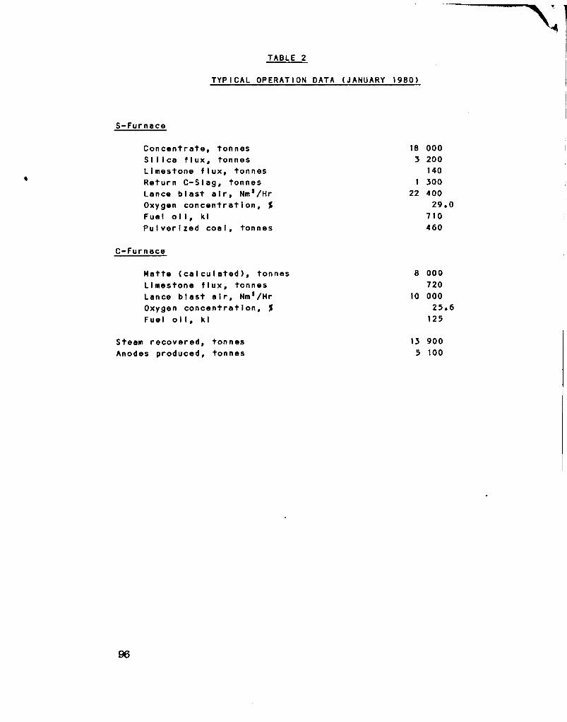
TABLE 2
TYPICAL OPERATION DATA (JANUARY 1980)
S-Furnace
C o n c e n t r a t e , tonnes 18 000 S i l i c a f l u x , tonnes 3 200 Limestone f l u x , tonnes 140 Return C - S l a g , tonnes 1 300 Lance b l a s t a i r , Nm'/Hr 22 400 Oxygen c o n c e n t r a t i o n , % 29.0 Fuel o i l , kl 710 P u l v e r i z e d c o a l , tonnes 460
C-Furnace
Matte ( c a l c u l a t e d ) , tonnes 8 000 Limestone f l u x , tonnes 720 Lance b l a s t a i r , Nm'/Hr 10 000 Oxygen c o n c e n t r a t i o n , % 25.6 Fuel o i l , kl 125
Steam r e c o v e r e d , tonnes 13 900 Anodes produced, tonnes 5 100
96

TABLE 3
TYPICAL ANALYSIS, %
Cu Fe
Con c e n t r a t e Si I l e a f l u x Limestone f l u x Matte D i s c a r d s l a g C-SIag
Anode
65.0 0.5 15.0
Cu
99.4
27.5 27.5
0.21
31.0
S i 0 2
5.5 90.0
11.0 22.0 42.0 0.7 30.2 44.0 < 0.1 < 0.2
Pb Ni Bi
0.03 0.01
CaO A I 2 O 3
0.5 1.5
53.0
4.2 3.3 15.0 < 0.2
As Sb
0.02 0.01
TABLE 4
ANODE PRODUCTION
Co n c e n t r a t e T r e a t e d
Ton nes Cu %
Anode Prod uced, Tonnes
October 1979 November December January 1980 February Ma r ch Apr I I May June Ju l y August cont i nu I ng
Average
15 100 18 000 18 800 18 100 16 500 16 400 14 400 18 100 17 500 17 100 17 600
17 050
27.6 28.7 28.2 27.5 27.3 26.9 26.5 27.0 27.2 25.7 24.9
470 090 100 150 470 770 490 750 650 360 040
4 480
97

TABLE 5
NUMBER OF LANCES
Lance Diameter S-Furnace Lances
C-Furnace Lances
O r i g i n a l Design 2 1/2 cm Recent P r a c t i c e 3 cm
10 6
TABLE 6
TYPICAL OPERATING CONDITION OF LANCES
Lance D i ameter Lance B l a s t S o l i d Charge (Average)
3 i nch 3000 Nm'/Hr/Lance
7 MT/Hr
98

TABLE 7
TYPICAL OPERATION DATA WITH AND WITHOUT COAL UTILIZATION
MODE OF OPERATION Fuel O i l Only O i l & Coal
C o n c e n t r a t e feed r a t e Fuel o i l Coal E q u i v a l e n t f u e l r a t e
MT/H 1/H
kg/H 1/H
26,2 1 ,370
0 1,370
27.0 850 645
1,300
TABLE 8
RESULTS OF HIGH OXYGEN ENRICHMENT TEST
O2 * of S-Furnace Lance B l a s t
Throughput tonnes per day
Fuel r a t e Fuel O i l - I / H Coal -kg/h
30*
500
1,100 300
50*
500
400 290
Of f - g a s Volume (S+C) Nm'/mln. 830 580
99

TABLE 9
ENERGY CONSUMPTION AT 100 OOP TONNE PLANT
Consumption Per Tonne Copper
Fuel Consumption, 73.3 I - i n c l u d i n g d r y e r , anode f u r n a c e s ,
launder h e a t i n g .
Power Consumption, - M a t e r i a l s h a n d l i n g , compressors
and blowers i n c l u d i n g f u g i t i v e gas trea t m e n t , e x c l u d i n g a c i d p l a n t 308 KWH
- P r o d u c t i o n of tonnage oxygen 162 " - E l e c t r i c f u r n a c e 323 "
T o t a l 793 KWH
Steam Recovered, 1.50 MT 40 kg/cm 2G, s a t u r a t e d
TABLE 10
SMELTING RATE
MITSUBISHI CONTINUOUS NA0SHIMA
(Model) (Reverb) TAMANO SAGANOSEK ( F l a s h ) ( F l a s h )
Annual c a p a c i t y , ton n es
O p e r a t i n g days per year Furnace volume, Ms
S m e l t i n g r a t e T/Ms/D
100 000
325* 1
670 0.46
96 000
350* 1
1,520* 2
0.18
94 000 110 000
3 2 5 * 1 325* 1
860 960 0.34 0.35
Note:
( 1 ) AssumptI on (2) Roaster Is Included
100

TABLE 11
FUGITIVE GAS COLLECTION
NaoshI ma ContInuous P I ant
Naosh!ma( l 0) Reverb
(CaIcIve)
0hahama( 1 1 ) Reverb
(Green)
Tamano( 1 2) F lash
Ann uaI Ca pac i t y , tonnes
48 000 96 000 146 000 94 000
Gas N e u t r a l i z a t i o n , Nm '/M Aci d pi ant taI I-gas Anode f 1 c e o f f - g a s Reverb o f f - g a s Secondary hood, e t c .
T o t a l
0
0* 1
0
0
2,600 500
0 0_
3,100
2,700 800
2,000 7, 100
12,600
0 500* 2
2,800
3,300
Fug 111ve Gas Co I I e c t Nms/M*3 500 4,500 5, 100 2,700
SO 2 Emission Allowed, Nm sS0 2/H E q u i v a l e n t e m i s s i o n , Nm 3SO 2/H/100,000T Cu
50 104
135 141
84 58
87 93
Note: 1) Anode furnace o f f gas during o x i d a t i o n are mixed to burner a i r . In autogenous mode of o p e r a t i o n , t h i s p a r t w i l l be sent to n e u t r a l i z a t i o n p l a n t or high stack depending on degree of a l l o w a b l e S0 2 e m i s s i o n .
2) Estimated f i g u r e . 3) These are a d d i t i o n a l to what are n e u t r a l i z e d n o r m a l l y , f i l t e r e d
and vented o f f .
101

TABLE 12
MAN POWER REQUIREMENT (UNIT; MAN-SHIFT/DAY)
M i t s u b i s h i Continuous P r o c e s s 100 000 T/Y Foreman Operator
Naosh i ma C o n v e n t i o n a l Reverb 96 000 T/Y Foreman Operator
Feed p r e p a r a t i o n 1 Sme l t i n g f u r n a c e 1 x 3 C o n v e r t i n g f u r n a c e 1 x 3 Anode furnace 1 x 3 Co n v e r t e r s l a g treatment Oxygen p l a n t M I see I Ianeous 1
T o t a l 8
2 + 1 x 3 2 2 + 3 x 3 7 x 3 1 x 3 6 x 3 7 x 3 1 x 3 7 x 3 5 x 3 1 x 3 5 x 3
1 4 + 3 x 3 1 x 3
5 1 1 1
55 13 89
102
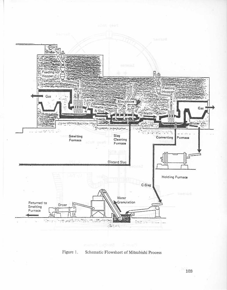
Smelting Furnace
Slag Cleaning Fumaca
Discard Slac
Converting
C-Slag
Fumaca
a •
Holding Furnacs
Returned to Smelting Furnace
Dryer
Fl
Figure 1. Schematic Flowsheet o f Mitsubishi Process
103
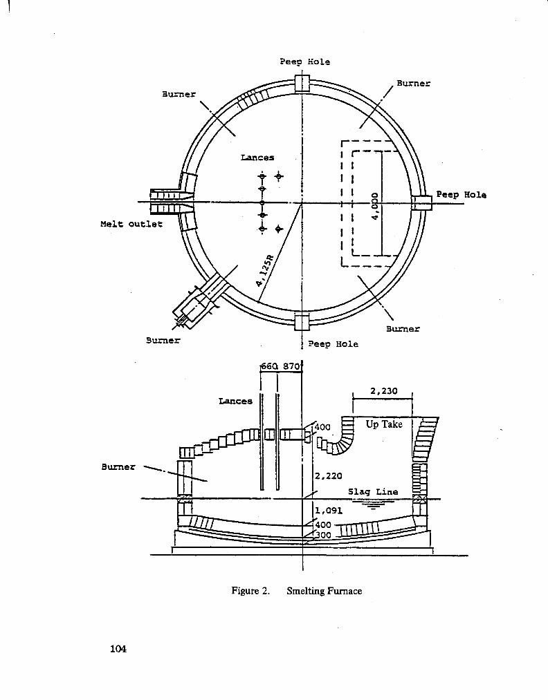
Peeo Hole
Burner
Peep Hole
Melt outlet
Burner
Figure 2. Smelting Furnace
104

[ X ] : Water Cooled Jacket | ( : Direct-Bonded Hagnesite-Chrome tsS^i z Fused-Cast Magnesite-Chrcme l-V'.-l : Tamped Periclasa
Figure 3. Converting Furnace 105

106
Figure 4. Schematic drawing showing feeding and lancing system

MODIFIED BURNER ARRANGEMENT
MELT OUTLET
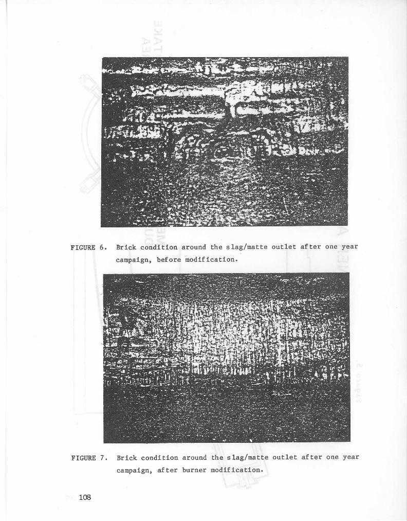
FIGURE 7. Brick condition around the slag/matte outlet after one year campaign, after burner modification.
108

1
30 40 50 60 S-FURNACE LANCE BLAST, 02%
Condition; - Based on the existing Naoshima plant, - S-Furnace lance blast being fixed at 15,000 Nnvj/H. - Concentrate analysis being assumed as Cu 28%, Fe 27%,
S32%,Si0 25%.
Figure 8. Increase of throughput by higher oxygen enrichment.
109

FUEL OIL 2,000 KG/H
1,500
1,000
500
30 40 50 ^60 70 S-LAIMCE, 02%
Concentrate Cu% Fe% S% SiO %
Type A 28 28 35 5 Type B 35 25 27 8 Type C Type B + 3 .4% c o a l
F i g u r e 9. F u e l requirement at 100,000 MT annual c a p a c i t y
110

APPENDIX
PROCESS CALCULATION OF MITSUBISHI CONTINUOUS COPPER SMELTING AND CONVERTING PROCESS
PROJECT NAME: COPPER SMELTING/REFINING TECHNOLOGIES SEMINAR, VANCOUVER, B.C., NOVEMBER 1980
ANNUAL CAPACITY: 101 000 TONNES COPPER PER YEAR
NOVEMBER 5, 1980
MITSUBISHI METAL CORPORATION
111
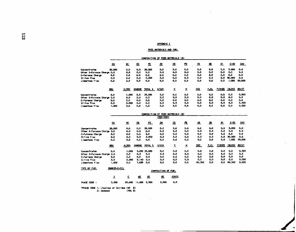
APPENDIX 1
FEED MATERIALS AND FUEL
COMPOSITION OF FEED MATERIALS (%)
CU Nl CO FE ZN CD PB AS SB B1 SI 02 CAP
Concentrates 28.000 0.0 0.0 28.000 0.0 0.0 0.0 0.0 0.0 0.0 5.000 0.0 Other S-Furnace Charge 0*0 0.0 0.0 0.0 0.0 0.0 0.0 0.0 0.0 0.0 0.0 0.0 C-Furnace Charge 0.0 0.0 0.0 0.0 0.0 0.0 0.0 0.0 0.0 0.0 0.0 0.0 Silica Flux 0.0 0.0 0.0 2.000 0.0 0.0 0.0 0.0 0.0 0.0 90.000 0.0 Limestone F I U K 0.0 0.0 0.0 0.0 0.0 0.0 0.0 0.0 0.0 0.0 1.000 50.000
MGU AL203 GANGUE TOTAL $ S/S03 C_ C02 F.CL FIXH20 1GLOSS MOIST
Concentrates 0.0 1.000 0.0 35.000 0.0 0.0 0.0 0.0 0.0 0.0 0.0 0.500 Other S-Furnace Charge 0*0 0.0 0.0 0.0 0.0 0.0 0.0 0.0 0.0 0.0 0.0 0.0 C-Furnace Charge 0.0 0.0 0.0 0.0 0.0 0.0 0.0 0.0 0.0 0.0 0.0 0.0 Silica Flux 0.0 2.000 0.0 0.0 0.0 0.0 0.0 0.0 0.0 0.0 0.0 0.500 LI ••stone Flux 1.000 0.0 0.0 0.0 0.0 0.0 0.0 0.0 0.0 0.0 0.0 0.500
COMPOSITION OF FEED MATERIALS (*) (REVISED)
CU Nl CO FE ZN CD PB AS SB Bl SI02 CAO
Concentrates 28.000 0.0 0.0 28.000 0.0 0.0 0.0 0.0 0.0 0.0 5.000 0.0 Other S-Furnace Charga 0*0 0.0 0.0 0.0 0.0 0.0 0.0 0.0 0.0 0.0 0.0 0.0 C-Furnace Charge 0.0 0.0 0.0 0.0 0.0 0.0 0.0 0.0 0.0 0.0 0.0 0.0 SI 1 tea Flux 0.0 0.0 0.0 2.000 0.0 0.0 0.0 0.0 0.0 0.0 90.000 0.0 Limestone Flux 0.0 0.0 0.0 0.0 0.0 0.0 0.0 0.0 0.0 0.0 1.000 50.000
MGU AL203 GANGUE TOTAL $ S/S03 c JH C02 F.CL FIXH20 IGLOSS MOIST
Concentrates 0.0 1.000 3.000 33.000 0.0 0.0 0.0 0.0 0.0 0.0 0.0 0.500 Other S-Furnace Charge 0.0 0.0 0.0 0.0 0.0 0.0 0.0 0.0 0.0 0.0 0.0 0.0 C-Furnace Charga 0.0 0.0 0.0 0.0 0.0 0.0 0.0 0.0 0.0 0.0 0.0 0.0 Silica Flux 0.0 2.000 3.140 0.0 0.0 0.0 0.0 0.0 0.0 0.0 0.0 0.500 Limestone Flux 1.000 0.0 7.638 0.0 0.0 0.0 0.0 40.342 0.0 0.0 40.342 0.500
TYPE OF FUEL BUNKER-C-OIL COMPOSITION OF FUEL
S. C H2. 02 N2 ASHES
PHASE CODE 1 3.000 85.000 11.000 0.500 0.500 0.0
•PHASE CODE I: Llqulous or Solldus (WT %) 2: Gaseous (VOL %)

APPENDIX 2
MATERIALS TO BE TREATED (DRY BASE)
M.T. PER YEAR M.T. PER YEAR M.T. PER DAY M.T. PER PER LINE PER LINE PER
S-INPUT
Concentrate 365000. 365000. 1 123. 52.00 Other S-Charge 0. 0. 0. 0.0 S1IIca F1 ux 66842. 66842. 206. 9.52 Limestone Flux 7151. 7151. 22. 1.02 Converter Slag 41658. 41658. 128. 5.93 S-Boiler Dust 3806. 3806. 12. 0.54 C-Boller Dust 900. 900. 3. 0.13 S-EP Dust 5008. 5008. 15. 0.71 C-EP Dust 1502. 1502. 5. 0.21 TOTAL INPUT 491867. 491867. 1513. 70.07
S-OUTPUT
Matte 167126. 167126. 514. 23.81 Discard Slag 245641. 245641. 756. 35.00 S-Boller Dust 3850. 3850. 12. 0.55 S-EP Dust 5089. 5089. 16. 0.73 S-Off Dust 0. 0. 0. 0.0 TOTAL OUTPUT 421706. 421706. 1,298. 60.08
C-INPUT
Matte 167126. 167126. 514. 23.81 Other C-Charge 0. 0. 0. 0.0 Limestone Flux 12504. 12504. 38. 1.78 TOTAL INPUT 179630. 179630. 553. 25.59
C-OUTPUT
BlIster Copper 101685. 101685. 313. 14.49 Converter Slag 41658. 41658. 128. 5.93 C-Boiler Dust 785. 785. 2. 0.1 1 C-EP Dust 1340. 1340. 4. 0.19 TOTAL OUTPUT 0. 0. 0. 0.0
C-OFF GAS 145468. 145468. 448. 20.72
BLEED OFF
Discard Slag 245641. 245642. 756. 35.00 S-Boller Dust 0. 0. 0. 0.0 S-EP Dust 0. 0. 0. 0.0 S-Off Gas 0. 0. 0. 0.0
TOTAL S-BLEED OFF 245641. 245641. 756. 35.00
C-Boller Dust 0. 0. 0. 0.0 C-EP Dust 0. 0. 0. 0.0 C-Off Gas 0. 0. 0. 0.0 C-Slag 0. 0. 0. 0.0
TOTAL C-BLEED OFF 0. 0. 0. 0.0
113
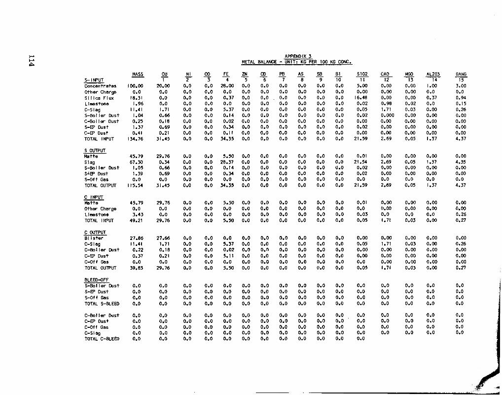
APPENDIX 3 METAL BALANCE - UNIT; KG PER 100 KG CONC,
MASS cu Nl CO FE ZN CD PB AS SB B1 S102 CAO MGO AL203 GANG S- INPUT 1 2 3 4 5 6 7 8 9 10 11 12 13 14 15 Concentrates 100.00 20.00 0.0 0.0 28.00 0.0 0.0 0.0 0.0 0.0 0.0 5.00 0.00 0.00 I.00 3.00 Other Charge 0.0 0.0 0.0 0.0 0.0 0.0 0.0 0.0 0.0 0.0 0.0 0.00 0.00 0.00 0.0 0.0 Silica Flux 18.31 0.0 0.0 0.0 0.37 0.0 0.0 0.0 0.0 0.0 0.0 16.48 0.00 0.00 0.37 0.94 Limestone 1.96 0.0 0.0 0.0 0.0 0.0 0.0 0.0 0.0 0.0 0.0 0.02 0.98 0.02 0.0 0.15 C-S1ag 1 1.41 1.71 0.0 0.0 5.37 0.0 0.0 0.0 0.0 0.0 0.0 0.05 1.71 0.03 0.00 0.26 S-Boller Dust 1.04 0.66 0.0 0.0 0.14 0.0 0.0 0.0 0.0 0.0 0.0 0.02 0.000 0.00 0.00 0.00 C-Boller Dust 0.25 0.18 0.0 0.0 0.02 0.0 0.0 0.0 0.0 0.0 0.0 0.00 0.00 0.00 0.00 0.00 S-EP Dust 1.37 0.69 0.0 0.0 0.34 0.0 0.0 0.0 0.0 0.0 0.0 0.02 0.00 0.00 0.00 0.00 C-EP Dust 0.41 0.21 0.0 0.0 0.11 0.0 0.0 0.0 0.0 0.0 0.0 0.00 0.00 0.00 0.00 0.00 TOTAL INPUT 134.76 31.45 0.0 0.0 34.35 0.0 0.0 0.0 0.0 0.0 0.0 21.59 2.69 0.05 1.37 4.37
S OUTPUT Matte 45.79 29.76 0.0 0.0 5.50 0.0 0.0 0.0 0.0 0.0 0.0 0.01 0.00 0.00 0.00 0.00 Slag 67.30 0.34 0.0 0.0 28.37 0.0 0.0 0.0 0.0 0.0 0.0 21.54 2.69 0.05 1.37 4.35 S-Boller Dust 1.05 0.66 0.0 0.0 0.14 0.0 0.0 0.0 0.0 0.0 0.0 0.02 0.00 0.00 0.00 0.00 S-EP Dust 1.39 0.69 0.0 0.0 0.34 0.0 0.0 0.0 0.0 0.0 0.0 0.02 0.00 0.00 0.00 0.00 S-Off Gas 0.0 0.0 0.0 0.0 0.0 0.0 0.0 0.0 0.0 0.0 0.0 0.0 0.0 0.0 0.0 0.0 TOTAL OUTPUT 115.54 31.45 0.0 0.0 34.35 0.0 0.0 0.0 0.0 0.0 0.0 21.59 2.69 0.05 1.37 4.37
C INPUT Matte 45.79 29.76 0.0 0.0 5.50 0.0 0.0 0.0 0.0 0.0 0.0 0.01 0.00 0.00 0.00 0.00 Other Charge 0.0 0.0 0.0 0.0 0.0 0.0 0.0 0.0 0.0 0.0 0.0 0.0 0.00 0.00 0.00 0.00 Limestone 3.43 0.0 0.0 0.0 0.0 0.0 0.0 0.0 0.0 0.0 0.0 0.03 0.0 0.0 0.0 0.26 TOTAL INPUT 49.21 29.76 0.0 0.0 5.50 0.0 0.0 0.0 0.0 0.0 0.0 0.05 1.71 0.03 0.00 0.27
C OUTPUT Blister 27.86 27.66 0.0 0.0 0.0 0.0 0.0 0.0 0.0 0.0 0.0 0.00 0.00 0.00 0.00 0.00 C-S1ag 11.41 1.71 0.0 0.0 5.37 0.0 0.0 0.0 0.0 0.0 0.0 0.05 1.71 0.03 0.00 0.26 C-Boller Dust 0.22 0.18 0.0 0.0 0.02 0.0 0.0 0.0 0.0 0.0 0.0 0.00 0.00 0.00 0.00 0.00 C-EP Dust 0.37 0.21 0.0 0.0 5.11 0.0 0.0 0.0 0.0 0.0 0.0 0.00 0.00 0.00 0.00 0.00 C-Off Gas 0.0 0.0 0.0 0.0 0.0 0.0 0.0 0.0 0.0 0.0 0.0 0.0 0.00 0.00 0.00 0.00 TOTAL OUTPUT 39.85 29.76 0.0 0.0 5.50 0.0 0.0 0.0 0.0 0.0 0.0 0.05 1.71 0.03 0.00 0.27
BLEED-OFF S-Boller Dust 0.0 0.0 0.0 0.0 0.0 0.0 0.0 0.0 0.0 0.0 0.0 0.0 0.0 0.0 0.0 0.0 S-EP Dust 0.0 0.0 0.0 0.0 0.0 0.0 0.0 0.0 0.0 0.0 0.0 0.0 0.0 0.0 0.0 0.0 S-Off Gas 0.0 0.0 0.0 0.0 0.0 0.0 0.0 0.0 0.0 0.0 0.0 0.0 0.0 0.0 0.0 0.0 TOTAL S-BLEED 0.0 0.0 0.0 0.0 0.0 0.0 0.0 0.0 0.0 0.0 0.0 0.0 0.0 0.0 0.0 0.0
C-Boller Dust 0.0 0.0 0.0 0.0 0.0 0.0 0.0 0.0 0.0 0.0 0.0 0.0 0.0 0.0 0.0 0.0 C-EP Dust 0.0 0.0 0.0 0.0 0.0 0.0 0.0 0.0 0.0 0.0 0.0 0.0 0.0 0.0 0.0 0.0 C-Off Gas 0.0 0.0 0.0 0.0 0.0 0.0 0.0 0.0 0.0 0.0 0.0 0.0 0.0 0.0 0.0 0.0 C-Slag 0.0 0.0 0.0 0.0 0.0 0.0 0.0 0.0 0.0 0.0 0.0 0.0 0.0 0.0 0.0 0.0 TOTAL C-BLEED 0.0 0.0 0.0 0.0 0.0 0.0 0.0 0.0 0.0 0.0 0.0 0.0

APPENDIX 4 COMPOSITION OF MATERIALS AND PRODUCTS (%)
MASS CU Nl CO FE ZN CD PB AS SB B1 SI 02 CAO MGO AL203 GANG s S-INPUT 1 2 3 4 5 6 7 8 9 10 11 12 13 14 15 16 Concentrates 100.00 28.00 0.0 0.0 28.00 0.0 0.0 0.0 0.0 0.0 0.0 5.00 0.00 0.00 1.00 3.00 35.00 Other Charge 0.0 0.0 0.0 0.0 0.0 0.0 0.0 0.0 0.0 0.0 0.0 0.00 0.00 0.00 0.0 0.0 0.0 Silica Flux 18.31 0.0 0.0 0.0 2.00 0.0 0.0 0.0 0.0 0.0 0.0 90.00 0.00 0.00 2.00 5.14 0.0 Limestone 1.96 0.0 0.0 0.0 0.0 0.0 0.0 0.0 0.0 0.0 0.0 1.00 50.00 1.00 0.0 7.66 0.0 C-SJag 11.41 15.00 0.0 0.0 47.07 0.0 0.0 0.0 0.0 0.0 0.0 0.43 15.00 0.30 0.01 2.32 0.0 S-BoMer Dust 1.04 63.35 0.0 0.0 13.18 0.0 0.0 0.0 0.0 0.0 0.0 2.07 0.03 0.00 0.13 0.42 7.18 C-Boller Dust 0.25 72.39 0.0 0.0 8.93 0.0 0.0 0.0 0.0 0.0 0.0 0.02 0.49 0.01 0.00 0.11 2.19 S-EP Dust 1.37 50.43 0.0 0.0 25.04 0.0 0.0 0.0 0.0 0.0 0.0 1.57 0.02 0.00 0.10 0.32 2.80 C-EP Dust 0.41 50.63 0.0 0.0 26.76 0.0 0.0 0.0 0.0 0.0 0.0 0.01 0.25 0.01 0.00 0.06 1.79 TOTAL INPUT 134.76 0.0 0.0 0.0 0.0 0.0 0.0 0.0 0.0 0.0 0.0 0.00 0.0 0.00 0.00 0.00 0.00
S OUTPUT Matte 45.79 65.00 0.0 0.00 12.02 0.0 0.0 0.0 0.0 0.0 0.0 0.03 0.00 0.00 0.00 0.01 22.24 Slag 67.30 0.50 0.0 0.0 42.15 0.0 0.0 0.0 0.0 0.0 0.0 32.00 4.00 0.08 2.03 6.47 0.13 S-Boller Dust 1.05 62.62 0.0 0.00 13.03 0.0 0.0 0.0 0.0 0.0 0.0 2.05 0.03 0.00 0.13 0.41 20.04 S-EP Dust 1.39 49.62 0.0 0.00 24.64 0.0 0.0 0.0 0.0 0.0 0.0 1.55 0.02 0.00 0.10 0.31 20.57 S-Off Gas 0.0 0.0 0.0 0.0 0.0 0.0 0.0 0.0 0.0 0.0 0.0 0.0 0.0 0.0 0.0 0.0 0.0 TOTAL OUTPUT 115.54 0.0 0.0 0.00 0.0 0.0 0.0 0.0 0.0 0.0 0.0 0.00 0.00. 0.00 0.00 0.00 0.00
C INPUT Matte 45.79 65.00 0.0 0.0 12.02 0.0 0.0 0.0 0.0 0.0 0.0 0.03 0.00 0.00 0.00 0.01 22.24 Other Charge 0.0 0.0 0.0 0.0 0.0 0.0 0.0 0.0 0.0 0.0 0.0 0.0 0.00 0.00 0.00 0.00 0.00 Limestone 3.43 0.0 0.0 0.0 0.0 0.0 0.0 0.0 0.0 0.0 0.0 1.00 50.00 1.00 0.0 7.66 0.0 TOTAL INPUT 49.21 0.00 0.0 0.0 0.0 0.0 0.0 0.0 0.0 0.0 0.0 0.0 o.o 0.0 0.00 0.00 0.00
C OUTPUT Blister 27.86 99.30 0.0 0.0 0.0 0.0 0.0 0.0 0.0 0.0 0.0 0.00 0.0 0.00 0.00 0.0 0.50 C-Slag 11.41 15.00 0.0 0.0 47.07 0.0 0.0 0.0 0.0 0.0 0.0 0.43 15.00 0.30 0.0) 2.32 0.0 C-BoIier Dust 0.22 83.04 0.0 0.0 10.24 0.0 0.0 0.0 0.0 0.0 o.o 0.02 0.56 0.01 0.00 0.12 0.0 C-EP Dust 0.37 56.75 0.0 0.0 29.99 0.0 0.0 0.0 0.0 0.0 0.0 0.01 0.28 0.01 0.00 0.07 0.0 C-Off Gas 0.0 0.0 0.0 0.0 0.0 0.0 0.0 0.0 0.0 0.0 0.0 0.0 0.0 0.0 0.0 0.0 0.0 TOTAL OUTPUT 39.85 0.0 0.0 0.0 0.0 0.0 0.0 0.0 0.0 0.0 0.0 0.0 0.0 0.0 0.0 0.0 0.0
BLEED-OFF S-BoMer Dust 0.0 0.0 0.0 0.0 0.0 0.0 0.0 0.0 0.0 0.0 0.0 0.0 0.0 0.0 0.0 0.0 0.0 S-EP Dust 0.0 0.0 0.0 0.0 0.0 0.0 0.0 0.0 0.0 0.0 0.0 0.0 0.0 0.0 0.0 0.0 0.0 S-Off Gas 0.0 0.0 0.0 0.0 0.0 0.0 0.0 0.0 0.0 0.0 0.0 0.0 0.0 0.0 0.0 0.0 0.0 TOTAL S-BLEED 0.0 0.0 0.0 0.0 0.0 0.0 0.0 0.0 0.0 0.0 0.0 0.0 0.0 0.0 0.0 0.0 0.0
C-Boller Dust 0.0 0.0 0.0 0.0 0.0 0.0 0.0 0.0 0.0 0.0 0.0 0.0 0.0 0.0 0.0 0.0 0.0 C-EP Dust 0.0 0.0 0.0 0.0 0.0 0.0 0.0 0.0 0.0 0.0 0.0 0.0 0.0 0.0 0.0 0.0 0.0 C-Off Gas 0.0 0.0 0.0 0.0 0.0 0.0 0.0 0.0 0.0 0.0 0.0 0.0 0.0 0.0 0.0 0.0 0.0 C-Slag 0.0 0.0 0.0 0.0 0.0 0.0 0.0 0.0 0.0 0.0 0.0 0.0 0.0 0.0 0.0 0.0 0.0 TOTAL C-BLEED 0.0 0.0 0.0 0.0 0.0 0.0 0.0 0.0 0.0 0.0 0.0 0.0 0.0 0.0 0.0 o.o 0.0

APPENDIX 5
LANCE BLAST AND BURNER AIR , NM3/NR
S-FURNACE C-FURNACE
Lance B I a s t 1
A i r 2
Tonnage Oxygen 3
Amount
19,I 15.0
9,610.0
9,505.0
02 PCT
57.6
20.6
95.0
Amount 02 PCT
17,113.8 29.8
15,002.1 20.6
2,111.7 95.0
TOTAL Amount
36,229.0
24,612.4
I I,616.6
Fuel Requirement 4 0.0
Burner A i r 5 0.0
A i r 6 0.0
Tonnage Oxygen 7 0.0
TOTAL TONNAGE OXYGEN
LANCE DIAMETER
MAXIMUM LANCE BLAST
NUMBER OF LANCES, S-Furnace C-Furnace
0.0
25.0
20.6
95.0
0.0
0.0
0.0
0.0
0.0
25.0
20.6
95.0
0.0
0.0
0.0
0.0
I I ,616.6/ NM 3/HR
3.0/IN.
3,000.0/ NM 3/HR
7.0 6.0
116

APPENDIX 6
GAS VOLUME AND COMPOSITION (WET BASIS)
S FURNACE OFF GAS Furnace BoIler Bo!ler EP Bo!ler EP
Gas Components Off-Gas Inlet Outlet Outlet Outlet Outlet (Normal) (Normal) (Max) (Max)
S02 PCT 1 50.45 48.05 44.65 42.52 37.89 36.08 02 PCT 2 0.00 0.98 1.45 2.36 4.35 5.12 C02 PCT 3 1.19 1.13 1.04 0.99 0.88 0.84 H20 PCT 4 3.32 3.26 3.16 3.1 1 2.99 2.94 S2 PCT 5 0.00 0.00 0.00 0.00 0.00 0.00 H2 PCT 6 0.00 0.00 0.00 0.00 0.00 0.00 CO PCT 7 0.00 0.00 0.00 0.00 0.00 0.00 N2 PCT 8 45.04 46.58 49.70 51.02 53.90 55.02
TOTAL PCT 9 100.00 100.00 100.00 100.00 100.00 100.00
TOTAL NM3/HR 10 17574.33 18453.05 20170.78 21179.31 23770.77 24959.31
C FURNACE OFF GAS Furnace Bo!ler Bo!ler EP Bo!ler EP
Gas Components Off-Gas Inlet Outlet Outlet Outlet Outlet (Norma 1) (Norma 1) (Max) (Max)
S02 PCT 1 22.10 21.05 19.13 18.22 16.13 15.36 02 PCT 2 3.95 4.74 6.09 6.78 8.37 8.95 C02 PCT 3 2.18 2.08 1.89 1.80 1.59 1.52 H20 PCT 4 1.86 1.86 1.88 1.88 1.90 1.90 S2 PCT 5 0.00 0.00 0.00 0.00 0.00 0.00 H2 PCT 6 0.00 0.00 0.00 0.00 0.00 0.00 CO PCT 7 0.00 0.00 0.00 0.00 0.00 0.00 N2 PCT 8 69.91 70.27 71.00 71.31 72.01 72.27
TOTAL PCT 9 100.00 100.00 100.00 100.00 100.00 100.00
TOTAL NM3/HR 10 16764.55 17602.77 19340.01 20307.01 22940.01 24087.01
Gas Compnents
FURNACE OFF GAS TOTAL (S+C) EP
Outlet EP
Outlet (Normal) (Max)
FURNACE OFF GAS TEMPERATURE S-FCE C-FCE
I250.°C I250.°C
S02 PCT 1 30.63 28.07 02 PCT 2 4.53 5.87 COS PCT 3 1.39 1.27 H20 PCT 4 2.51 2.47 S2 PCT 5 0.0 0.0 H2 PCT 6 0.0 0.0 CO PCT 7 0.0 0.0 N2 PCT 8 60.95 62.33
TOTAL PCT 9 100.00 100.00
TOTAL NM3/HR 10 41486.32 45266.32
117

APPENDIX 7
S-FURNACE HEAT BALANCE
UNIT AMOUNT KG(NM/3) /IOOKG
INPUT
Metallurg Reactions 0.0 Solid Feed 134.758 Molten Feed 0.0 Fuel Combustion 0.0 TOTAL INPUT 0.0
UNIT HEAT HEAT AMOUNT VALUE VALUE KCAL/ KCAL/ MCAL/ KGCW/3) IOOKG HR
0.0 60701.4 31564.7 4.0 539.0 280.3 0.0 0.0 0.0
10194.2 0.0 0.0 0.0 61240.5 31845.0
OUTPUT
Matte/Blister 45.788 216.0 9890.2 5142.9 Slag/C-Slag 67.299 319.0 21468.4 I I 163.5 Dusts 2.449 500.0 1224.5 636.0 Off Gases
S02 17.051 685.0 11680.0 6073.0 02 -0.000 451.2 0.0 0.0 CU2 0.402 683.7 275.0 143.0 H20 1.121 533.7 598.5 311.2 S2 0.0 451.2 0.0 0.0 H2 0.0 402.5 0.0 0.0 CO 0.0 431.2 0.0 0.0 N2 15.222 426.2 6488.4 3374.0
TOTAL OFF GASES 33.797 0.0 19042.0 9901.8
HEAT LOSSES 0.0 0.0 9615.4 5000.0
TOTAL OUTPUT 0.0 0.0 61240.5 31845.0
BALANCE 0.0 0.0 0.0 0.0
118

APPENDIX 8
C-FURNACE HEAT BALANCE
UNIT AMOUNT KGCNM/3) /IOOKG
INPUT
Metallurg Reactions 0.0 Solid Feed 3.426 Molten Feed 45.788 Fuel Combustion 0.0 TOTAL INPUT 0.0
UNIT HEAT HEAT AMOUNT VALUE VALUE KCAL/ KCAL/ MCAL/ KG(W/3) IOOKG HR
0.0 22676.4 11791.7 4.0 13.7 7.1
196.0 8974.5 4666.7 10194.2 0.0 0.0
0.0 31664.6 16465.6
OUTPUT
Matte/Blister 27.859 182.0 5070.3 2636.6 Slag/C-Slag 11.413 325.0 3709.3 1928.8 Dusts 0.5823 500.0 291.1 151.4 Off Gases
S02 7.126 685.0 4881.0 2538.1 02 1.273 451.2 574.6 298.8 CU2 0.703 683.7 481.0 250.1 H20 0.598 533.7 319.4 166.1 S2 0.0 451.2 0.0 0.0 H2 0.0 402.5 0.0 0.0 CO 0.0 431.2 0.0 0.0 N2 22.539 426.2 9607.2 4995.7
TOTAL OFF GASES 32.240 0.0 15863.1 8248.8
HEAT LOSSES 0.0 0.0 6730.8 3500.0
TOTAL OUTPUT 0.0 0.0 31664.6 16465.6
BALANCE 0.0 0.0 0.0 0.0
119

V

SECTION V
THE OUTOKUMPU FLASH SMELTING METHOD
BY K. MURDEN J. SULTANO

THE OUTOKUMPU COMPANY
Outokumpu i s the largest raining and metallurgical company in Finland. With an annual turnover of about 600 million dollars in 1979 the company ranks among the country's top industrial enterprises.
Two major shareholders are the Finnish Government and the Social Insurance Institute of Finland. Employees at twenty-one individual units throughout Finland total nearly 9,500.
Activ i t i e s f i r s t began when the Outokumpu copper ore body in eastern Finland was discovered in 1910. Today Outokumpu operates nine mines, four metallurgical plants, the Technical Export Division, a Metallurgical Research Institute, an Institute of Physics and an Exploration Department.
The main metal products are copper and copper alloys, stainless steel, zinc, cobalt, nickel and ferrochrome.
CPTOKUMPU FLASH SMELTING PROCESS
The basis of the Outokumpu Flash finelting Process for sul f i d i c ores i s the replacement of the conventional methods separate roasting and smelting by a combined roasting, smelting and part-converting process carried out in one unit. The heat generated by the exothermic reactions can thus be used for anelting the ore, so that only a small amount of additional energy i s needed. The recovery of waste heat from the furnace off-gases further improves the energy efficiency of the process. Smelting of dried, fine-grained concentrate in suspension, which offers the best conditions for rapid reactions, i s a characteri s t i c feature of the process.
HISTORY OF THE OUTOKUMPU FLASH SMELTING PROCESS
The shortage of electrical energy in Finland in World % r II caused Outokumpu to consider replacing the electric furnace anelting of copper concentrates by another method. After a careful study Outokumpu decided to develop the flash smelting process, which gives a considerable saving on fuel and yields a high recovery of sulfur. The pilot plant testing of the new process was carried out in 1947-1948.
122

Hie process was adopted for the anelting of copper concentrates on a comnercial scale in 1949 and applied successfully to the anelting of nickel concentrates at the Harjavalta Works in 1959.
In 1962 Outokumpu adopted a variant of the process, in which elemental sulfur i s recovered from the gases after thermal decomposition of pyrite in the flash anelting furnace. This process and the normal flash anelting process can be combined to produce elemental sulfur from anelter gases.
In 1971 oxygen enrichment in flash anelting was adopted in the Harjavalta copper and nickel anelters which gave considerable improvement in capacity and energy efficiency.
A commercial scale flash anelter producing blis t e r copper in flash smelting furnace was started in 1978 in Poland.
PROCESS DESCRIPTION
The main process steps at a modern flash anelter are:
(1) Feed preparation and drying. (2) Flash anelting and gas treatment. (3) Converting. (4) Anode casting. (5) Slag cleaning.
FEED PREPARATION AND DRYING
When the feed to the anelter consists of several concentrates, these should be mixed to make the feed as homogenous as possible. The homogeneity of the feed makes the flash anelting process easier to control. Fluxing agents are normally mixed with the concentrate before drying.
Fine grained feed has to be dried before going to the flash anelting furnace in order to ensure sufficiently rapid ignition and oxidation of the sulfides. There are several drying methods, the most common of them being co-current rotary drying. Heat needed for drying
123
i s provided ty burning f o s s i l fuels. Hot gases from the anode furnace or other sources can also be used for drying.
FLASH SMELTING
Dried feed and flue dust obtained by cleaning the furnace gas are fed together with the process a i r at a controlled rate into the concentrate burner at the top of the vertical, cylindrical reaction shaft.
Process a i r i s either oxygen-enriched air preheated up to 250° or ambient a i r preheated up to 400°-1000°C. Oxygen-enriched a i r i s preheated with steam, whereas high preheating c a l l s for an o i l or gas fi r e d preheater.
The concentrate oxidizes in the reaction shaft in the concentrate-a i r suspension and flows towards the horizontal settler. Heat generated ty the exothermic oxidation reactions anelts the solid particles. Molten material f a l l s to the bottom of the settler, where i t separates into matte and slag layers.
Part of the feed flows with process gases as flue dust and i s circulated from the gas line back to the flash smelting furnace feed. Impurities which have a high vapour pressure w i l l concentrate in the flue dust and can be removed from the process and recovered by handling the dust in a separate process.
CONVERTING AND ANODE CASTING
Flash smelting furnace matte i s taken to the converter to be blown with a i r or with oxygen-enriched air, thus producing blis t e r copper. Converter slag i s transported to the slag cleaning process or poured back to the flash anelting furnace. The converter gases are conducted after cleaning to the sulfuric acid plant.
Sometimes blister copper i s the end product of a anelter, but usually i t i s cleaned in the anode furnace and cast into anodes. Anode furnace gases can be used in a concentrate dryer.
124

SLAG CLEANING
The slags from the flash anelting furnace and the converter contain so much copper and other valuable metals that their recovery i s economically worthwhile. Recovery i s carried out either by cleaning slag in an electric furnace or by flotation.
In the electric furnace cleaning slag i s tapped either continuously or batchwise into the electric furnace to be reduced with coke. This reduces the solubility of copper in slag, and the copper thus settles as matte to the bottom of the furnace to be taken to the converter.
When using the flotation process the slags are cooled slowly, crushed, ground and f lota ted. Flotation concentrate i s fed through the dryer back to the flash anelting furnace.
GAS TREATMENT
Gas from the flash anelting furnace flows through the uptake shaft into the waste heat boiler, where i t cools to about 350°C. Waste heat i s recovered as steam. Gas from the boiler i s conducted through electrostatic precipitators to the sulfuric acid plant. Flue dust i s recovered in the boiler and in the electrostatic precipitator and fed back into the flash anelting furnace.
REQUIREMENTS FOR A M3DERN SMELTER INSTALLATION
To make a profitable anelter investment, the process selected must meet several, partly contradictory, requirements; the most important of these are r e l i a b i l i t y , f l e x i b i l i t y , low investment and operating costs, free from pollution and occupational safety and health hazards.
RELIABILITY
The process mist use proven techniques and be completely understood, so that the equipment can be designed and dimensioned to meet the requirements of the process. Over 30 years 1 experience in flash smelting, together with intensive research and development work at Outokumpu's plants and Research Centre, guarantees the r e l i a b i l i t y of the modern Outokumpu Flash Smelting Process. Hie theoretical basis
125

of the process i s well-known, thus a reliable plant can be planned for different kinds of conditions and a wide variety of raw materials.
Outokumpu has developed an effective training system for customers' staff to ensure proper operation of licensed flash anelting processes. The best evidence of the r e l i a b i l i t y i s that Outokumpu has sold twenty-six copper flash anelting licences a l l over the world.
INVESTMENT POSTS
The requirement of low investment costs conflicts with many of the other demands made of the process, for example with r e l i a b i l i t y and environmental protection. A compromise has to be made on the different requirements and this always depends on local conditions. In comparison with other anelters, an Outokumpu-type flash anelter i s fully competitive in terms of investment costs.
The flash smelting furnace can be designed for high feed rates especially when high oxygen enrichment in process a i r or pure oxygen i s used for oxidation. Some flash anelters have a production capacity of 200 000 tonnes per year of copper in one flash anelting furnace and the limit has been put by other factors than anelter capacity like availab i l i t y of concentrates, marketing of products etc. The high unit capacity in flash anelting decreases the investment cost in relation to the produced copper amount.
When using oxygen-enriched process air, especially in flash smelters of higher capacity, investment costs are as much as 10% lower than in a flash anelter with the same capacity using preheated process a i r ; at the same time other requirements for the anelter are more readily met.
FLEXIBILITY
The f l e x i b i l i t y of a anelter i s of the utmost importance in maintaining the planned production and i t s quality, even with raw materials of varying quality. Maximum production can be achieved by stabilizing the matte grade in the anelting furnace at the optimum level; in other words, the degree of oxidation of the concentrate must be regulated according to the varying composition of the concentrate, so that fluctuations do not disturb process stages after anelting.
126

The f l e x i b i l i t y of the flash anelting process i s based on the fact that in suspension anelting the degree of oxidation can be rapidly and easily regulated by changing the ratio of concentrate to oxygen in the process a i r . The only requirement i s that the quality of the feed mixture i s known in advance so that the process parameters can be calculated.
Effective elimination of impurities at the various process stages i s a prerequisite for maintaining a product of uniform quality. Flash smelting makes i t possible to remove most of the impurities in the concentrate into the slag or flue dust in the anelting furnace by setting the temperature and the degree of oxidation of the reaction zone to a suitable level. Temperature regulation i s especially easy when a anelter uses oxygen-enriched process a i r .
RECOVERY OF VALUABLE METALS
Recovery of valuable metals from the raw materials greatly affects the p r o f i t a b i l i t y of a smelter.
At an Outokumpu-type flash anelter the losses due to material handling are minimized because dry concentrates and dusts are conveyed in completely closed systems and process gases from the anelter are ef f i c i e n t l y cleaned by electrostatic precipitators.
Losses of valuable metals in the waste slag are minimized by cleaning the slags from the flash anelting furnace and the converter either in an electric furnace or in a slag concentrator. The copper content of the waste slag at a copper flash anelter varies from 0.3 to 0.6%, depending mainly on the cleaning method.
Due to high matte grade the usage of fluxes can be minimized in flash anelter which despite saving energy and material also minimizes the waste slag amount and thus increases the copper recovery.
OPERATING COSTS
The operating costs of a smelter, i.e. labour, energy and material costs, play a decisive role in p r o f i t a b i l i t y . At an Outokumpu-type flash smelter they are low compared to other types of anelters.
127

To reduce labour costs, a flash anelter can be highly automated. In the flash anelting furnace area, process staff are needed only for controlling and tapping purposes. The consumption of maintenance and other materials i s low. Hie consumption of brick-lining materials, for example, i s only about 1.0-1.5 kg per tonne of copper for the entire smelter. Refractory consumption in flash anelting furnace i s low due to a protective cooling system in the reaction shaft and settler. Converter throughput during campaign i s high because of high matte grade obtained in the flash anelting furnace.
ENERGY REQUIREMENTS
The greatest influence on anelting techniques has been the decreasing use of hydrocarbon fuels to stem the rise in operating costs. External energy requirements can be decreased by:
(1) Better u t i l i z a t i o n of the concentrate energy by raising matte grade.
(2) Recovery of heat.
(3) Efficient u t i l i z a t i o n of heat.
Many papers have been published on the consumption of energy i n copper production including the assessment of flash anelting, i n d i cating that oxygen enrichment with high grade matte production reduces energy requirements.
Hie use of oxygen reduces the gas volume, decreasing the heat carried out of the system and also fuel requirements. Since the gas volume decreases i t means that a given unit can increase throughput. It enables a furnace to operate without any fuel addition.
Increasing the matte grade increases the heat produced in burning the concentrate, as shown in Table 1, and also improves the heat recovery in the system by decreasing the latent energy passing to the converters.
128

Process a i r preheating produces an effect similar but not as influential as oxygen enrichment. As steam i s available, i t i s an obvious choice for temperatures up to 250°C with saturated steam and higher with super-heated steam. O i l heaters are also used, normally up to 500°C, but in one or two cases up to 1000°C, the economics and control do not compare with oxygen-enrichment used. Table 2 shows a heat balance for a flash smelting furnace with oxygen-enriched a i r .
Table 2 also shows the heat recovery for Pierce Smith converters. The difference in efficiency of heat recovery of the two systems i s evident from the figures. Under normal circumstances i t i s not economical to recover heat from converter gases because of the low recovery and the cyclic nature of the process, which in practice reduces efficiency further and increases capital costs.
Another factor to be considered i s the use of the recovered heat as steam. In many studies the assumption has been made that steam i s converted into electrical energy. From the viewpoint of a purely theoretical study of energy usage this may be satisfactory, but for an economic study this i s not an optimum solution. At the Ikrjavalta Smelter and two other anelters (one in operation and the other under construction) power generation i s not the most economic alternative and steam has been used in the saturated form. Saturated steam can be used for low temperature preheating, drying, o i l heating, local ( d i s t r i c t heating) and in a copper tankhouse. Hie oxygen plant can be run by elec t r i c or steam power (super-heated steam).
The flash smelting process i s flexible in regard to energy sources. A l l hydrocarbon fuels can be used in the flash anelting furnace; fuel consumption can be minimized by using high oxygen enrichment in flash anelting process air, the oxygen being produced by elect r i c energy or a superheated process steam. The price of electric power has not increased as rapidly as the price of hydrocarbon fuels and therefore fuel-free anelting has become even more attractive than before.
Outokumpu's fferjavalta anelter has been operated so that the consumption of fuel o i l i s only 25 kg per tonne of concentrate, and elec t r i c power i s 255 kwh per tonne concentrate for the whole anelter, including the oxygen plant, acid plant and infrastructure. The steam
129

credit at the same time i s 0.6 t/t concentrate of saturated 40 bar steam. In a larger scale anelter, energy consumption i s relatively lower.
ENVIFOMENTAL ASPECTS
The march of progress has brought with i t a great awareness of the environment. Less i s being taken for granted and more i s being carried out to diminish the impact of industry on nature.
What i s being done in the smelter today?
F i g u r e I shows the sulfur recovery throughout the l i f e of the flash smelting complex in Harjavalta, Finland. One can summarize the results in that the sulfur recovery has been in excess of 90% since the installation of the acid plant.
Is tliat enough?
Let us examine the flash anelter from the following viewpoints: ( i ) Atmospheric Emissions, ( i i ) Operational Conditions, ( i i i ) Water Pollution.
(i) ATMOSPHERIC EMISSIONS
Metallurgical Processing
At the anelter in Harjavalta approximately 300 000 tonnes of sulfide material i s treated annually, containing copper, nickel, iron, sulfur, lead, zinc, arsenic, and antimony, and additional chemical precipitates containing copper and nickel originating from the Kokkola cobalt and zinc plants and the Harjavalta nickel refinery.
Raw Materia1 Hand1ing
A characteristic of the metallurgical plants i s that they process raw materials containing various amounts of valuable metals. Hie concentrates are usually fine-grained and the amounts processed annually come up to several hundred thousand tonnes.
130

The transportation, storing, drying, and feeding of the concentrates are associated with considerable problems caused by dusting. These problems are not always easy to overcome and they require disproportionately large investments. A great deal of attention has been paid to the matter in the last few years, resulting, for example, in the construction of large covered concentrate storages. This has proved to be economical i f the valuable metal content in the concentrate i s high.
In most processes the concentrates must be dried to zero-moisture content before further treatment. At the plants of Outokumpu, the concentrate i s dried in co-current rotary driers heated by heavy fuel o i l . Dust i s removed from the t a i l gases in electrostatic precipitators or wet scrubbers and fed back to the process.
Dust and Gases in Smelting
The flash smelting method uses fine-grained dry sulfide concentrate both as a principal fuel and as a raw material for metal production. The process generates S02-bearing gases, which contain considerable amounts of solid particles. Owing to the nature of the process, the dust should not constitute a direct environmental problem because i t has, in any case, to be removed from the gases before the S O 2 i s converted to sulfuric acid or in some cases to elemental sulfur.
Converting
The copper converter matte contains between 65%-70% Cu and the nickel matte approximately 50% nickel and copper. Gases and particulates are collected in double hood systems.
Slag Treatment
The real waste from the anelting process i s slag. At the Harjavalta copper anelter, the slags from both the flash anelter and the converter are cast into big blocks, which are slowly cooled. During cooling, the copper crystallizes as a sulfide mineral, which, after the crushing and milling of the moulds, i s
131

separated by flotation. The copper concentrate i s fed back to the process and the fayalite slag i s pumped to a t a i l i n g pond.
The slags from the ftirjavalta nickel anelter are cleaned in an electrical furnace to recover nickel, and the molten fayalite slag i s then granulated and stored in big heaps. The storing of the slags in the neighbourhood of the anelter causes some environmental problems.
Sulfur Dioxide
In the older copper anelting methods, SO2 has been vented directly into the atmosphere but this practice i s now prohibited in many parts of the world. The regulations vary from one country to another, but representative requirements have been presented by the E.P.A. (U.S. Environmental Protection Agency):
Not more than 10% of the sulphur entering the anelter may be emitted to the atmosphere.
The yearly average SO* content anywhere at ground level must not exceed 0.03 ppn (by volume).
The average SO2 content anywhere at ground level on any day must not exceed 0.14 ppn.
The two main methods for fixing SO2 from anelter gases are: manufacture of sulfuric acid and reduction to elemental sulfur.
The recovery in both systems i s dependent on the sulfur dioxide content of the gas in question. Hie manufacture of sulfuric acid i s economically feasible when SO2 content of the gases i s more than 4%.
The flash anelting process was originally developed to reduce fuel requirements, but i t has incidentally led to other process efficiencies and to more effective and economical pollution control. The SO2 content of the flash anelting off-gases i s i n general very high, and as the gas volume i s very stable, the gases are most suitable for producing sulfuric acid.
132
Hie distribution of sulfur in the flash anelting system di f f e r s from the conventional anelting methods in that the sulfur i s confined essentially to the gas lines of the furnace and converter as a rich 302-bearing gas, the gas lines carrying the main load. This i s illustrated in Figure II for a concentrate containing 25% CU, 29% Fe, and 32% S, smelted to four different matte grades.
The combination of these gases from the Outokumpu flash smelter and the converter gases enables a higher recovery of sulfur with standard operating units. Hie sulfur losses in the smelter are outlined in Figure II.
The total recovery of sulfur at the anelter i s 97.8%. Hie average recovery of sulfuric acid from the gases at Harjavalta i s 99.7%, giving an overall recovery of sulfur as acid of 97.5%. The total emission to the atmosphere i s 1.3% of the total feed.
The sulfur discarded with the slag i s not dangerous to the surroundings, because i t does not oxidize into gaseous products nor dissolve in water.
Hie ventilation gases from the flash anelter furnace section, matte launders and ladles in a modern plant can be recycled to the process a i r fans to be utilized as process a i r in the reaction shaft. At Harjavalta these gases and the fugitive gases from the converter hood are vented to the stack. Using a high stack, environmental damage can be minimized. For example, the theoreti c a l ground-level concentrations for 70,000 Ifa3 t a i l gas containing 500 ppm SO2 have been calculated in Table 3 using d i f f e r ent wind velocities and stack heights.
"Ground Level Measurements
According to ground level measurements carried out i n 1975 the following approximate amounts of metals were found in the surroundings of the Harjavalta Works (measuring radius 18 Ian): copper 230 tonnes per annum, nickel 35 tonnes per annum, zinc 350 tonnes per annum, lead 400 kg per annum, cadmium 40 kg per annum, mercury 250 kg per annum, arsenic 6 tonnes per annum.
133

The amounts present in the s o i l in the area, plant protection agents, other future industrial emissions, and global background settlement have not been distinguished from these observed values.
The measured settlement of was 5300 tonnes per annum. The results of total emission calculated from the measured settlements in such a vast area (1017 km2) cannot be reliable, but conclusions on the magnitude of the emissions can be made.
The results of the measurements are probably too high, for when the wind strength rises even a l i t t l e above normal on the arenaceous s o i l typical of the area i t raises settled dust again into the a i r .
Ground level measurements were carried out in a smaller area in 1976 and 1977 giving dust emissions of the same magnitude as in 1975. Measurements show that zinc spreads considerably wider than other metals. The high zinc load in the years 1975-1977 i s due to the fact that some of the slag from the copper furnace had to be reduced in an electric furnace in those days. Today the 9 MVA ele c t r i c furnace has been replaced and zinc emissions from the plant have gone down to half of that shown above.
Measuring the Quality of Air
The company has not carried out any measurements on the quality of the a i r . The oxygen plant in the plant area uses an on-stream analyzer to observer S0 2 contents. The analyzer controls the quality of inlet a i r and should the SO2 contents rise too high the air inlet i s changed to another pipeline. Thus the equipment in question i s not used for measuring higher contents. The highest S02 content i s 860 per ug per ms. The background content has been about 50 per ug per ms • Airborne particulates have not been measured. A fundamental survey of the research into a i r protection in the town of Harjavalta was started towards the end of 1977, and the town together with industry w i l l cover the costs. The study should be completed by the end of 1979.
134
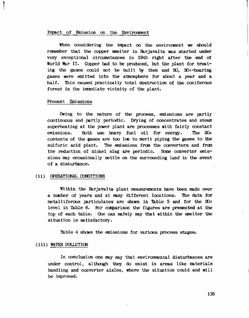
!
Impact of Emission on the Environment
When considering the impact on the environment we should remember that the copper smelter in Harjavalta was started under very exceptional circumstances in 1945 right after the end of World Viar II. Copper had to be produced, but the plant for treating the gases could not be built by then and SO, SO2-bearing gases were emitted into the atmosphere for about a year and a half. This caused practically total destruction of the coniferous forest in the immediate vicinity of the plant.
Present Emissions
Owing to the nature of the process, emissions are partly continuous and partly periodic. Drying of concentrates and steam superheating at the power plant are processes with f a i r l y constant emissions. Both use heavy fuel o i l for energy. The SO 2
contents of the gases are too low to merit piping the gases to the sulfuric acid plant. The emissions from the converters and from the reduction of nickel slag are periodic. Some converter emissions may occasionally settle on the surrounding land in the event of a disturbance.
( i i ) OPERATIONAL CONDITIONS
Within the Ikrjavalta plant measurements have been made over a number of years and at many different locations. The data for metalliferous particulates are shown in Table 5 and for the SO2
level in Table 6. For comparison the figures are presented at the top of each table. One can safely say that within the smelter the situation i s satisfactory.
Table 4 shows the emissions for various process stages.
( i i i ) WATER POLLUTION
In conclusion one may say that environmental disturbances are under control, although they do exist in areas like materials handling and converter aisles, where the situation could and w i l l be improved.
135
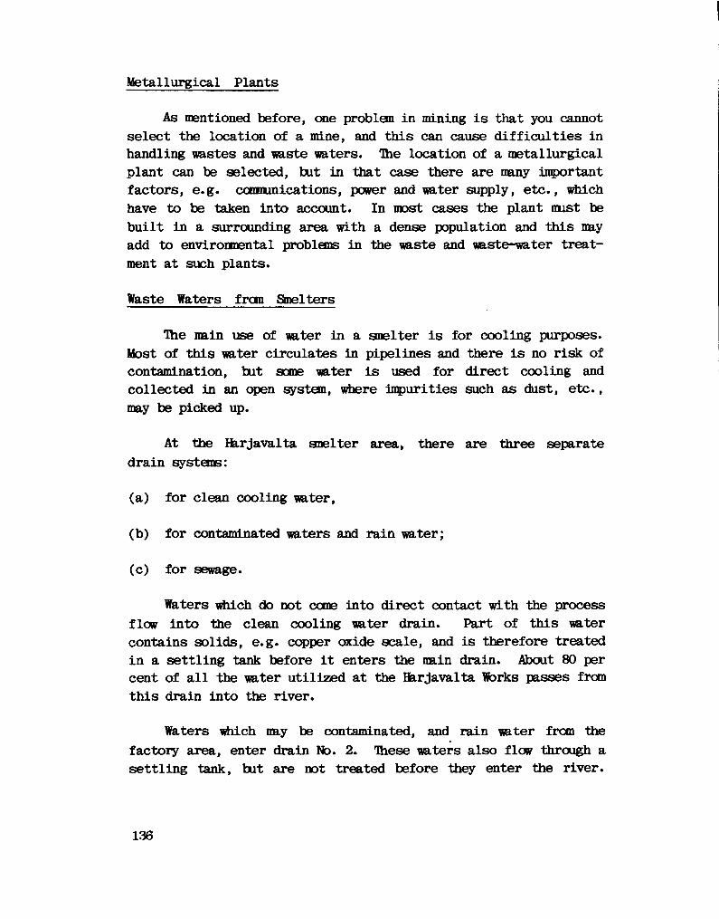
Metallurgical Plants
As mentioned before, one problem in mining i s that you cannot select the location of a mine, and this can cause d i f f i c u l t i e s in handling wastes and waste waters. The location of a metallurgical plant can be selected, but in that case there are many important factors, e.g. communications, power and water supply, etc., which have to be taken into account. In most cases the plant must be bu i l t in a surrounding area with a dense population and this may add to environmental problems in the waste and waste-water treatment at such plants.
Waste Waters from Smelters
The main use of water in a smelter i s for cooling purposes. Most of this water circulates in pipelines and there i s no risk of contamination, but some water i s used for direct cooling and collected in an open system, where impurities such as dust, etc., may be picked up.
At the Harjavalta smelter area, there are three separate drain systems:
(a) for clean cooling water,
(b) for contaminated waters and rain water;
(c) for sewage.
Waters which do not come into direct contact with the process flow into the clean cooling water drain. Part of this water contains solids, e.g. copper oxide scale, and i s therefore treated i n a settling tank before i t enters the main drain. About 80 per cent of a l l the water uti l i z e d at the Harjavalta Works passes from this drain into the river.
Waters which may be contaminated, and rain water from the factory area, enter drain No. 2. These waters also flow through a settling tank, but are not treated before they enter the river.
136
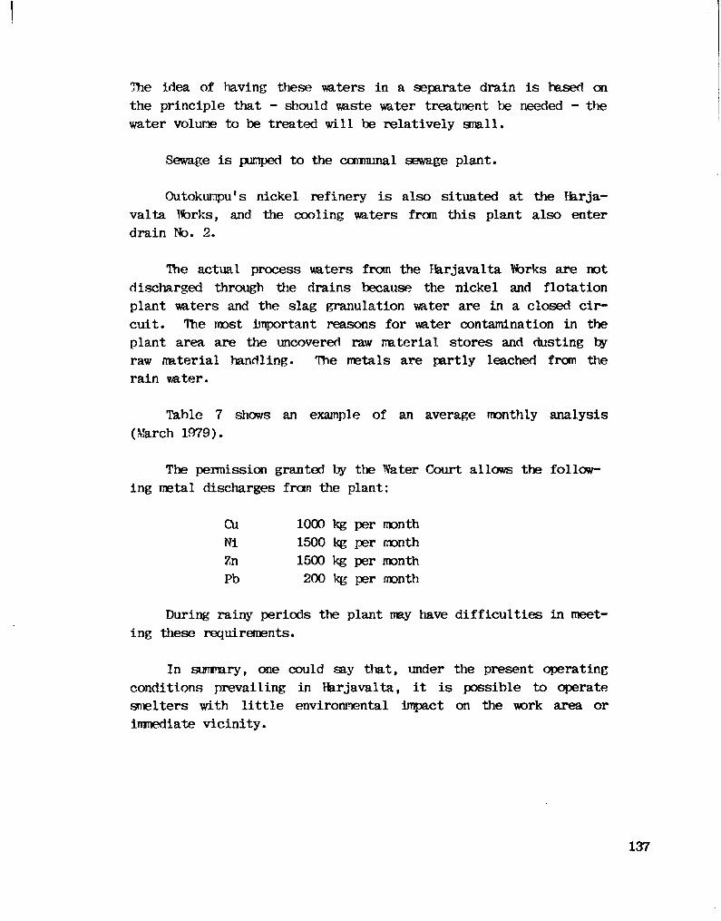
The idea of having these waters in a separate drain i s based on the principle that - should waste water treatment be needed - the water volume to be treated w i l l be relatively small.
Sewage i s pumped to the communal sewage plant.
Outokumpu f s nickel refinery i s also situated at the Harjavalta Works, and the cooling waters from this plant also enter drain No. 2.
The actual process waters from the Harjavalta Works are not discharged through the drains because the nickel and flotation plant waters and the slag granulation water are in a closed c i r cuit. Hie most important reasons for water contamination in the plant area are the uncovered raw material stores and dusting by raw material handling. The metals are partly leached from the rain water.
Table 7 shows an example of an average monthly analysis (March 1979).
The permission granted by the Water Court allows the following metal discharges from the plant:
During rainy periods the plant may have d i f f i c u l t i e s in meeting these requirements.
In summary, one could say that, under the present operating conditions prevailing in Harjavalta, i t i s possible to operate smelters with l i t t l e environmental impact on the work area or immediate vi c i n i t y .
Cu Ni Zn Pb
1000 kg per month 1500 kg per month 1500 kg per month 200 kg per month
137
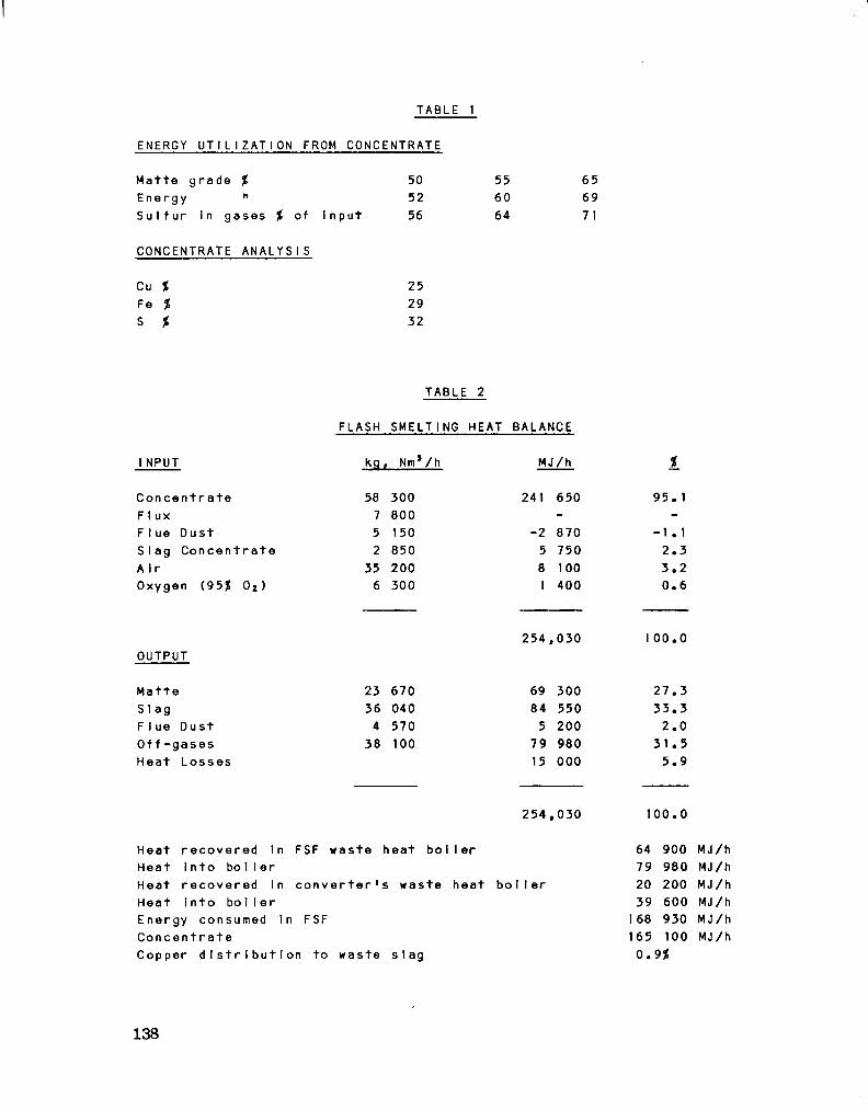
TABLE 1
ENERGY UTILIZATION FROM CONCENTRATE
Matte grade % 50 Energy " 52 S u l f u r in gases % of input 56
55 60 64
65 69 7 1
CONCENTRATE ANALYSIS
Cu % Fe % S %
25 29 32
TABLE 2
FLASH SMELTING HEAT BALANCE
I NPUT kg, Nm8/h MJ/h
C o n c e n t r a t e F I ux F I ue Dust SIag C o n c e n t r a t e A i r Oxygen {95% 0 2)
58 300 800 150 850
35 200 6 300
241 650
-2 870 5 750 8 100 I 400
95. 1
-1 . 1 2.3 3.2 0.6
OUTPUT 254,030 100.0
Matte 23 670 69 300 27.3 Sla g 36 040 84 550 33.3 Flue Dust 4 570 5 200 2.0 O f f - g a s e s 38 100 79 980 31.5 Heat Losses 15 000 5.9
254,030 100.0
Heat r e c o v e r e d in FSF waste heat b o i l e r Heat i n t o b o i l e r Heat r e c o v e r e d in c o n v e r t e r ' s waste heat b o i l e r Heat into boi Ier Energy consumed in FSF Co n c e n t r a t e Copper d i s t r i b u t i o n to waste s l a g
64 900 MJ/h 79 980 MJ/h 20 200 MJ/h 39 600 MJ/h
168 930 MJ/h 165 100 MJ/h
0.9%
138
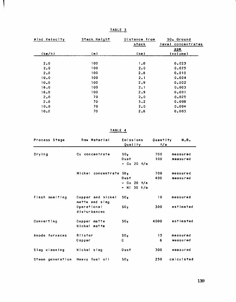
TABLE 3
Wind V e I o c I t y Stack Height D i s t a n c e from S0 2 Ground s t a c k l e v e l c o n c e n t r a t e s
22HL ( km/h ) (m) ( km) (volume)
2.0 100 1 .0 0.025 2.0 100 2.0 0.025 2.0 100 2.8 0.010 10.0 100 2.1 0.004 10.0 100 2.9 0.002 18.0 100 2.1 0.003 18.0 100 2.9 0.001 2.0 70 2.0 0.025 2.0 70 3.2 0.008 10.0 70 2.0 0.004 10.0 70 2.8 0.003
TABLE 4
Process Stage Raw M a t e r i a l E m i s s i o n s Qua I Ity
Q u a n t i t y N.B. t / a
D rying
F l a s h sme11 i ng
Convert i ng
Anode fu r n a c e s
Cu c o n c e n t r a t e S0 2
D ust - Cu 20 t/a
N i c k e l c o n c e n t r a t e SO2 Dust
Copper matte N i ckel matte
BIi s t e r Copper
Slag c l e a n i n g N i c k e l stag
Steam g e n e r a t i o n Heavy f u e l o i l
- Cu 20 t/a - Nl 30 t / a
Copper and n i c k e l SO2 matte and s l a g O p e r a t i o n a l S0 2
d i s t u r b a n c e s
S0 2
S0 2
C
Dust
S0 2
700 measured 100 measured
700 400
4000
15 6
300
250
meas ured measured
10 measured
300 e s t i m a t e d
e s t i mated
measured measured
measured
c a l c u l a t e d
139
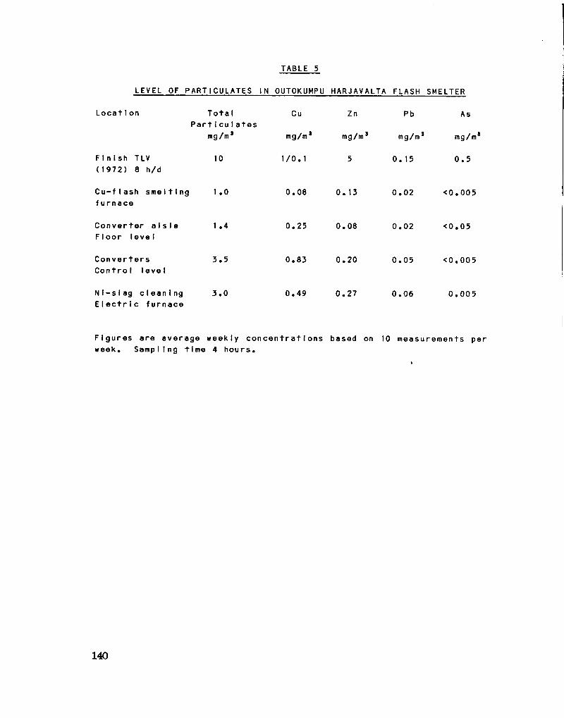
TABLE 5
LEVEL OF PARTICULATES IN OUTOKUMPU HARJAVALTA FLASH SMELTER
L o c a t i o n T o t a l Cu Zn Pb As P a r t i c u l a t e s
mg/m3 mg/m3 mg/m3 mg/m3 mg/m3
F i n i s h TLV 10 1/0.1 5 0.15 0.5 (1972) 8 h/d
C u - f l a s h s m e l t i n g 1.0 0.08 0.13 0.02 <0.005 furna c e
C o n v e r t e r a i s l e 1.4 0.25 0.08 0.02 <0.05 FIoor I eve I
C o n v e r t e r s 3.5 0.83 0.20 0.05 <0.005 C o n t r o l l e v e l
N i - s l a g c l e a n i n g 3.0 0.49 0.27 0.06 0.005 E l e c t r i c furnace
F i g u r e s are average weekly c o n c e n t r a t i o n s based on 10 measurements per week. Sampling time 4 hours.
140

TABLE 6
SULFUR DIOXIDE CONCENTRATION IN OUTOKUMPU HARJAVALTA FLASH SMELTER
L o c a t i o n Week Number of Highe s t peak 8-hour average (1) measurements c o n c e n t r a t i o n average (2)
ppm ppm
F i n n i s h TLV (1972) 8 h/d
C u-f I ash s m e l t i n g f u r n a c e
1 .1 36 25 0.4-2.1
Con v e r t e r a i s l e FIoor l e v e l
0.2 36 0.1-0.4
C o n v e r t e r s C o n t r o l l e v e l
1 .3 43 25 0.2-2.3
N i - s I ag cIean i ng E I e c t r i c furnace
0.9 36 25 0.3-2.3
(1) Geometric mean (2) Min. and max. of 8-hour average during one week, geometric mean.
141

TABLE 7
Drain for Drain for T o t a l loss of c l e a n water other waters metals i n t o
1 2 the d r a i n s
Cu mg/1 0.04 Ni mg/1 < 0.04 Zn ng/1 0.06 Pb mg/1 < 0.01 Conduct i v i ty
m S/m Amount of water c u b i c metres/day 37000
1.2 320 kg/month 3.1 < 880 kg/month 1.7 530 kg/month 0.04 11 kg/month
19
8600
142

F I G U R E I
SULPHUR DISTRIBUTION AT
THE HARJAVALTA WORKS
100
80
1000 tons
60
40
20
sulphur smelter sulphur to acid plant
1950 1960 » —
1970
atmospheric emission
1980
143

F I G U R E I I
SULPHUR DISTRIBUTION DIAGRAM
Atm. loss 0.5%
Gas 72.7%
i Sulphuric Acid Plant
Sulphuric acid 97.4% •
Atm. loss 0.2% Atm. loss 0.3% Gas 25.2% Atm. Joss 0.8%
Smelter Feed 100%
M
Flash Furnace Feed 103,0%
Flash Smelting Furnace
Matte 27.9% Converting and Anode Casting Shop
Anodes 0%
J
Slaq 2,1% Slag 1,9%
Slag Concentrate 3.2%
Slag Flotation Plant Tailing 0. Slag Flotation Plant
SECTION VI
BANQUET SPEECH
ADDRESS BY THE HOT. R.H. KfcCLEJJLAND MINISTER OF I2TERGY, MINES ft PETROLEUM RESOURCES
NOVEMBER 5, 1980

Good evening, ladies and gentlemen:
On behalf of the Government of British Cblumbia, I'd like to welcome you to our Province, to the City of Vancouver and to this Smelting and Refining Technologies Seminar.
We have guests here this evening from many parts of the world; from other parts of Canada; from the United States; from Australia and the Fhillipines, Europe and Japan ... welcome. In the course of your stay with us, I hope you w i l l be able to see some of the sights and take part in ac t i v i t i e s that are uniquely Brit i s h Columbian ... especially those best experienced under the protection of an umbrella.
My Ministry i s pleased to have had the opportunity to organize this seminar, the goals of which are to increase awareness in the mining community of the potential for copper smelting in this province, of the technologies applicable to Britis h Cblumbia ores, and of our energy, economic and environmental circumstances which have a bearing on smelting and refining.
This seminar i s very much a learning experience for us a l l . My Ministry i s interested to hear of your plans and prospects, so as to be better equipped to lend assistance i f and when proposals are submitted.
I note from your program that the seminar w i l l include a number of highly technical talks on the merits of various smelting processes. I have been asked to give a sort of furnace-side chat to accompany these learned discussions. Well, this evening I would like to present in general terms the B.C. Government's policy framework for copper smelting and refining, outlining some of the potential benefits as well as the possible risks — as we see them.
Fi r s t , I would like to digress for a moment, to review something of B r i t i s h Columbia's past history in copper smelting. For the lessons of history contain many of the issues facing us today, as we consider the prospects of new smelting and refining f a c i l i t i e s in this province.
146
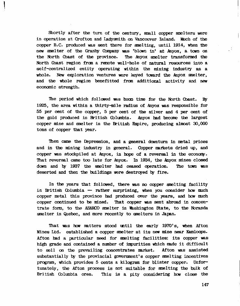
Shortly after the turn of the century, small copper smelters were in operation at Crof ton and Ladysmith on Vancouver Island. Much of the copper B.C. produced was sent there for smelting, u n t i l 1914, when the new smelter of the Granby Company was 'blown in' at Anyox, a town on the North (bast of the province. The Anyox smelter transformed the North Coast region from a remote well-hole of natural resources into a self-centralized entity operating within the mining industry as a whole. New exploration ventures were keyed toward the Anyox smelter, and the whole region benefitted from additional activity and new economic strength.
Hie period which followed was boom time for the North Coast. By 1925, the area within a thirty-mile radius of Anyox was responsible for 55 per cent of the copper, 5 per cent of the silver and 4 per cent of the gold produced in British Cblumbia. Anyox had become the largest copper mine and smelter in the British Empire, producing almost 30,000 tons of copper that year.
Then came the Depression, and a general downturn in metal prices and in the mining industry in general. Copper markets dried up, and copper was stockpiled at Anyox, in hope of a reversal in the economy. That reversal came too late for Anyox. In 1934, the Anyox mines closed down and by 1937 the smelter had ceased operation. The town was deserted and then the buildings were destroyed by f i r e .
In the years that followed, there was no copper smelting f a c i l i t y i n British Cblumbia — rather surprising, when you consider how much copper metal this province had produced over the years, and how much copper continued to be mined. That copper was sent abroad in concentrate form, to the ASAR00 smelter in Washington State, to the Noranda smelter in Quebec, and more recently to smelters in Japan.
That was how matters stood until the early 1970's, when Afton Mines Ltd. established a copper smelter at i t s new mine near Kamloops. Afton had a particular need for smelting f a c i l i t i e s : i t s copper was high grade and contained a number of impurities which made i t d i f f i c u l t to s e l l on the prevailing concentrates market. Afton was assisted substantially by the provincial government's copper smelting incentives program, which provides 5 cents a kilogram for bl i s t e r copper. Unfortunately, the Afton process i s not suitable for smelting the bulk of B r i t i s h Cblumbia ores. This i s a pity considering how close the
147
smelter i s to the Highland Valley, this province's principal copper producing region.
This historical review brings us to the c r i t i c a l question: should B r i t i s h Cblumbia undertake to establish new copper smelting and refin ing f a c i l i t i e s to up-grade our ores? That i s the question I would like to consider with you now.
Let's look f i r s t at the economics of copper smelting in British Columbia, in general terms. Traditionally, we have held a strong position in the world copper concentrates markets. This position i s based on our sizeable copper production and our access to tidewater and the Ra.cific RLm markets. We export approximately one quarter of a b i l l i o n kilograms of concentrates a year, which makes us one of the free world's largest concentrate exporters.
However, in the next few years, world copper smelting f a c i l i t i e s w i l l be approaching f u l l capacity ut i l i z a t i o n . We expect the Japanese smelters to be at capacity ty 1985, and I understand that Japan i s not planning substantial expansions. I am told that in the united States some smelter capacity i s being retired. So, by mid-decade, the world may well be looking for new smelter sites.
In the Rsicific region, a number of sites present themselves. Of these, Briti s h Cblumbia possesses several distinct advantages: stable economic and p o l i t i c a l climates; ample energy resources; good labour relations; and most importantly, immediate access to substantial reserves of copper. So, now might be a very good time for serious consideration of new copper smelting capacity in B r i t i s h Cblumbia.
The chief benefit to British Cblumbia of such a move would be the economic impact, both locally and internationally. New smelting f a c i l i t i e s would result in additional activity in construction and other industries, additional employment in many sectors, regional development and a better outlook for the province's mining industry. Indeed, we would realize many of the same gains and advantages, on a province-wide scale, as were f e l t at Anyox many years ago.
But the chief economic gain would be made in the international copper markets. Prices tend to fluctuate on both the world concentrate
148
and world metal markets; and usually, when the price for copper concentrate i s relatively low, the price for copper metal i s relatively high. These prices move in relation to one another, and right now, Bri t i s h Columbia i s not in a position to take advantage of this interlocking market for our copper. By developing smelting capacity in this province, we would be able to make some direct economic gain, but more importantly, we could provide greater s t a b i l i t y for Bri t i s h Cblumbia mining industry ty participating in both concentrates and metals markets.
The next link in the copper chain, the copper fabrication i n dustry, would be that much closer to realization, assuming the right economic climate. Copper smelting f a c i l i t i e s in Br i t i s h Cblumbia would contribute to our copper self-sufficiency, as well as improving our position on world copper markets.
For years, smelting activity has been located close to the markets for finished products, with l i t t l e processing activity in the producing regions. That i s changing. The clear and absolute orientation in both areas has been breaking down for some time now. The diversification of our role in the world copper market seems in order a broadening of our industry's base, and an opportunity to provide greater economic s t a b i l i t y .
Now, what about the potential risks involved in new smelting ventures i n Br i t i s h Cblumbia?
One of the chief concerns about copper smelters anywhere has been their impact on the environment. Any new smelter in Br i t i s h Cblumbia would be subject to the government's Guidelines for Intensive Development. We have enabling legislation in place and are in the process of fi n a l i z i n g the guidelines themselves, which w i l l serve to assess the environmental and socio-economic impact of major industrial projects such as smelters.
Now, government regulation i s rarely popular with proponents of industrial development. However, this government believes i n streamlining the regulatory process as much as possible. Such i s the case in our major energy projects review process, and such w i l l , I am sure, be the case with the Guidelines for Intensive Development. In each case
149

we want to ensure maximum benefit to the province from the development of i t s resources, while at the same time making sure that other less tangible resources, such as quality of l i f e or the integrity of the environment in which we live, are not lost along the way.
I am told that contemporary smelting and refining technologies are becoming more and more sophisticated, with less pollution and better sulfur recoveries. Never again w i l l we see in this province the denuded hi l l s i d e s and slag heaps and polluted rivers and streams that were present at Anyox in the early years. The Afton operation i s a case in point. It i s one of the cleanest copper smelting plants in the world. The company went to some lengths, in response to local concerns and government regulations, to make sure the environmental impact of the smelter would be minimal. Smelters have a bad name among environmentalists, but Afton i s doing i t s part to change that. And so are we a l l . Our site-specific environmental guidelines are one of the ways to achieve this end.
The other risk involves the economics of copper smelting. We must ask ourselves whether the investment of risk capital in smelting and refining in this province i s worthwhile. After a l l , B r i t i s h Cblumbia copper interests already have a strong place in the concentrates markets, as I have said. However, we would hope to increase our total copper sales, by f u l f i l l i n g our present concentrate contracts and se l l i n g copper metal as well. I wish to emphasize that government policy i s not intended to promote further mineral processing at the expense of our presently attractive concentrate markets. Our industry i s viable at the moment; but we are always on the lookout for new opportunities which w i l l enhance the value of our resources and broaden the base of our economy.
Whatever decisions are taken on smelting and refining in British Columbia, I am sure that this province w i l l remain a reliable supplier of concentrates to the world market. We w i l l honour our contracts and continue to play a role in f i l l i n g the world's copper needs. We certainly have enough copper to enter the copper metals markets; we have the location, the economic and industrial base, and access to advanced copper smelting and refining technologies, as this seminar clearly shows. I guess i t comes down to a matter of timing and economics. The government i s cautiously optimistic about British Columbia's copper
150

smelting prospects. We look forward to hearing from the industry on this subject, when they think the time i s right.
Meanwhile, I wish you f r u i t f u l discussions at this conference, as you explore the technological side of British Cblumbia1 s smelting prospects.
Ladies and gentlemen, I would be remiss i f I did not take advantage of this my f i r s t opportunity to respond in a considered manner to the federal governments recently announced budget and energy program.
I can't t e l l you, in absolute terms, exactly how much the budgetary moves and energy proposals are going to cost B r i t i s h Cblumbia. O f f i c i a l s in my ministry and in the Ministry of Finance are s t i l l working out the dollar figures. But preliminary estimates indicate that these moves w i l l have a direct and detrimental impact on various sectors of our economy, and that they w i l l seriously undermine our efforts to achieve energy security for this province.
I can t e l l you that this budget, with i t s centre-fold spread energy program, w i l l have the immediate effect of setting industry against government, and government against government; and that as soon as the impact of the new energy taxes begins to be f e l t ty consumers, that w i l l set individual Canadians from a l l parts of this land against the government in Ottawa. They w i l l demand to know, in clear terms, why they are being taxed, and exactly how their money i s being spent.
This i s a deceptive budget. On the surface, i t looks good for the individual taxpayer. By means of this deception, the federal government hopes to buy some time. It hopes to distract the attention of Canadians from the pressing matters of the economy and energy security, by giving them the impression Ottawa has these matters well in hand. In fact, that's just not so.
This so-called budget i s no more than a money-grab and a power-grab. It shifts a disproportionate amount of the economic burden of energy self-sufficiency from the federal government onto Canadian consumers, onto the producing provinces and the energy industries. It does so in an underhanded manner. Ottawa hopes to suddenly discover a
151

whole pi l e of what appears to be extra revenues, which i t w i l l then happily use to pay off i t s d e f i c i t — the product of more turn a decade of liberal f i s c a l mismanagement — and then to pay off i t s p o l i t i c a l debts in central Canada, thereby ensuring re-election.
Most seriously of a l l , this budget i s being used by the federal government to gather more and more power unto i t s e l f , changing this country constitutionally, through non-constitutional means. There seems no limit to what this government i s prepared to do to get i t s way.
Let's consider for a moment some of the specific proposals contained i n the budget and the energy program.
(1) Blended Price for O i l
Until now, Ottawa has paid the difference between the domestic price and the world price for o i l through the o i l import compensation program. Hiey have used normal taxation revenues to do so. The new blended price for o i l i s a continuation of th i s policy. However, once the blended price i s phased in, the cost w i l l no longer be borne by the federal government. Rather, i t w i l l be paid by the Petroleum Compensation charge, which w i l l be levied on refineries, and then passed directly on to the consumers. By this move, the federal government w i l l save i t s e l f an estimated 4.3 million dollars per day and do next to nothing to bring a f a i r return to the producing provinces on their depleting o i l reserves. The net result i s that Canadian consumers w i l l be paying more for o i l , producing provinces w i l l not be getting anywhere near replacement value for their o i l , and Ottawa w i l l find i t s e l f with a lot of extra money to play around with.
(2) Natural Gas Excise Tax
The federal government says i t wants Canadians to switch off o i l and onto other more plentiful energy sources, such as natural gas. They say price w i l l be a prime incentive. Yet they turn around and slap an excise tax and a special charge on that very commodity. Canadian consumers, trying to help make Canada more energy secure, pay again.
152
In addition, Ottawa has decided to place an export tax on natural gas. They won't c a l l i t an export tax, per se, but that's what i t i s . And Br i t i s h Cblumbia remains unalterably opposed to i t .
They just i f y these taxes on natural gas in a number of far-fetched ways. For instance, they say the federal government has a right to a share of the western energy resource revenues, which they c a l l unwarranted windfall profits. That's pious rationalization. The real reason for the tax comes a few pages further on i n their energy document: "The federal government i s seriously short of the revenue i t requires to manage the Canadian economy." They could raise these revenues through normal taxation means, and cut their own expenses at the same time. But that might be unpopular, especially in central Canada.
So Ottawa needs revenues, which i t intends to capture through devious means. That seems to be the bottom line to a l l their energy tax proposals:
- The 8 per cent (plus) tax on net operating revenues of o i l and gas companies;
The Canada-lands incentives, which w i l l encourage o i l and gas activity there, at the expense of operators in other regions and at the same time w i l l bring revenues from the north and the off-shore directly back to Ottawa;
The Canadianization of the o i l and gas industries, which w i l l be paid for ty consumers, from which Ottawa w i l l gain d i v i dends, and which w i l l not produce one more barrel of o i l or Mcf of natural gas for Canada;
The Natural Gas bank, which w i l l allow Ottawa to buy gas cheap from the small companies i t has driven to the brink of bankruptcy, and then s e l l i t at a profit.
I haven't time this evening to go into a l l these programs in deta i l . But you get the general d r i f t . The impact of Ottawa's moves,
153

in terms of direct costs, w i l l f a l l f i r s t on the petroleum and natural gas and related industries, then on the producing provinces, and throughout the whole process, on Canadian consumers of energy. Never i n the history of Canada has there been such direct and unilateral intrusion by government into the a c t i v i t i e s and income of specific sectors of the economy. And who says i t w i l l necessarily stop there. The budget papers include provisions to remove from mining exploration companies certain tax depletion allowances — a signal of intended federal intrusion into other resource sectors. And never has there been proposed, by any truly federal government, anywhere, such a complete and relentless raid on the revenues of regions within the nation.
As I say, we don't yet know the f u l l impact of these policies on B r i t i s h Cblumbia*s economy or on our energy security. We won't know u n t i l we see the f u l l extent of Ottawa's raid on provincial treasuries. We won't know until we see how much money the federal government plans to take out of the pockets of individual British Cblumbians. We won't know until we have a sense of the damage done in the o i l and gas industries and the private sector as a whole, or un t i l we learn how these policies w i l l affect energy pricing and supply, the two chief elements of our energy security. Unfortunately, when we do know, i t may be extremely d i f f i c u l t to repair the damage.
I'd like to conclude by talking for a moment about sharing. Mr. MacEachen said in his budget speech that "the concept of sharing seems to be close to the distinctive fibre of the Canadian tradition." The federal government admits, with respect to natural resource revenues, that there i s "no legislatively-defined arrangement under the B.N.A. Act for sharing". In other words, as we have been saying a l l along, the provinces own their resources.
Nevertheless, we have shared with our fellow Canadians. B r i t i s h Columbia has paid into the federal equalization program almost since i t s inception. And we have, through t a r i f f s on imported goods, paid to support central Canada's manufacturing industry for many years. And we are not alone in our sharing. In July, the province of Alberta, which also pays into equalization, offered to share more of i t s new-found wealth with the rest of Canada, through transportation, energy and other in i t i a t i v e s , to the benefit of a l l Canadians. If only the
154
federal government would allow them a f a i r price for their depleting energy resources. But they were turned down f l a t . Obviously, as far as Ottawa was concerned, they didn't offer to share enough. We haven't offered to share enough. How much i s enough?
In the federal government's energy document, they say that "the revenue share accruing to each level of government i s a function of a mixture of f i s c a l instruments that has evolved over time." Well, the f i s c a l instruments imposed unilaterally by Ottawa's current proposals defines clearly their concept of sharing. To them, sharing means grabbing as much revenue as they can possibly get their hands on.
The west has shared willingly, over the years, because we agree that sharing JLs what Canada i s a l l about. Now we are not being asked to share, we are being told to share. We are being told we are the bad boys of confederation. We are being told that, while we own our resources, they are not really ours to control. They are Ottawa's to take, whether we like i t or not.
It's as i f we are si t t i n g in on a card game where the stakes are high and where the dealer makes up the rules as he goes along, to serve his own advantage. Our resource ownership has been turned into a worthless p i l e of chips. If we bet and win, our winnings go to Ottawa; i f we bet and lose, we take the losses.
By i t s budgetary and energy proposals, the federal government has put Briti s h Cblumbia and the other energy producing provinces, and the energy companies, and the Canadian consumer into a no-win situation. Either we fold what we know i s a good hand, and pay the dealer, or we get up from the table and walk away from the game. That's a* terrible choice for Canadians to have to make. And as Bri t i s h Cblumbians and good Canadians, we don't want to be forced to make i t .
Thank you very much.
155

SECTION VII
APPLICATION OF THE SHERRITT-OQMINOO UUPPER PROCESS TO BRITISH COLUMBIA
COPPER CONCENTRATES
BY P. KAWULKA C.R. KIRBY

SHERRITT GORDON MINES LIMITED AND OOMINOO LTD.
APPLICATION OF THE SHERRITT-OOMINOO COPPER PROCESS TO BRITISH COLUMBIA
COPPER CONCENTRATES
BY P. KAWULKA * C. R. KIRBY **
This paper i s to be presented at the British Columbia Copper Smelting and Refining Technologies Seminar to be held in Vancouver, B.C. on November 5 and 6, 1980. The seminar i s organized by the B.C. Ministry of Energy, Mines and Petroleum Resources.
If and when this paper i s published, i t may embody certain changes made by the authors so that the form in which i t appears here i s not necessarily that in which i t may be published later.
* Formerly Co-Manager S-C Copper Project, presently Head Environment, Engineering & Planning Department, Sherritt-Gordon Mines Limited, Fort Saskatchewan, Alberta.
** Senior Research Engineer, Technical Research, Cominco Ltd., T r a i l , British Columbia.
158

ABSTRACT
The S-C Copper Process has been adapted to treat a typical British Columbia copper concentrate. A process flow diagram, a schematic flow diagram and process description are presented for 75 000 tonnes per year copper rod production from copper concentrate. Basic operating requirements are outlined and a preliminary estimate of operating and capital costs for a western Canada location are summarized. The costs are compared with those of an equivalent modern flash snelter/electro-refinery.
159

iNTRonucriw
The S-C Copper Process was developed by Sherritt Gordon 1 lines Limited and Cbminco Ltd. to f i l l a need for an improved alternative to smelting.
Laboratory work was conducted jointly by both companies. Technical f e a s i b i l i t y was demonstrated in a 9 tonnes per day integrated pilot plant (1-2). Commercial evaluation showed the S-C Copper Process to have substantial advantages over flash smelting (3). The salient features of the process are:
- 98% or better recovery of copper with quality equal to electro-refined.
- Gold and silver recoveries comparable to smelting.
- Recovery of 60-90% of the sulfur in elemental form, the remainder being in a discardable residue.
- Recovery of associated metal values such as molybdenum and zinc as saleable by-products.
- A considerable measure of r e l i e f obtained from problems of hygiene because of total containment of the process.
- Applicability to a wide range of concentrate grades and compositions.
- Competitive costs as compared to a modern flash smelter/electro-refinery.
The process was developed for a low grade f&nitoba copper concentrate, chalcopyrite with substantial pyrite, also containing recoverable zinc values in addition to gold and silver. For this presentation the process was adapted to treat a bornite-chalcopyrite concentrate of a composition more typical of British Columbia. The concentrate analyses are shown in Tkble 1. This analysis does not refer to a specific concentrate but i s a copper grade obtained by a calculated weighted average representing present and future concentrates. The British
160
Columbia concentrate contains insufficient zinc to warrant separate recovery and has less sulfur and iron per unit of copper which makes i t easier to treat than the Kfenitoban concentrates ty the S-C Process.
To ill u s t r a t e the economics, a preliminary design and cost e s t i mate have been prepared for a 75 000 tonnes per year S-C Copper Plant located in Western Canada. These costs, which are adapted from a previous study (12), compare favourably with those of an equivalent modern flash stnelter/electro-refinery.
mNCENTRATE DESCRIPTION
Representative analysis of Jfenitoba and British Cblumbia copper concentrates are compared in Tkble 1.
PROCESS DESCRIPTION
The following main steps are required for processing B.C. concentrates :
(a) Iron Removal Circuits
Thermal activation. Acid leach. Jarosite precipitation.
(b) Copper Winning Circuits
Oxidation leach. Purification. Electrowinning or hydrogen reduction.
The flowsheet i s shown in Figure 1. It i s a simplification of the basic flowsheet which was designed to treat concentrate of much greater complexity than the B.C. concentrate being considered. The design i s based on key laboratory tests and on a computerized mass balance. Typical analyses of the main process streams are shown in Table 2.
161

THERMAL ACTIVATION
A key feature of the S-C Copper Process i s a thorough removal of iron from the concentrate prior to the solubilizing of copper. For the B.C. concentrate this i s achieved through thermal activation of the concentrate to make iron adequately and selectively soluble in a subsequent non-oxidizing sulfuric acid leach.
The activation takes place in two stages in a multi-hearth roaster. In the f i r s t stage about 12% of the concentrate sulfur i s removed by thermal decomposition of pyrite and chalcopyrite at 680°C. In the second stage a further 4% i s removed as hydrogen sulphide by counter flowing hydrogen. The calcine so produced corresponds to a mixture of bornite (CusFeS*) and t r o i l i t e (FeS).
The reactions are:
Delabilization (First Stage)
Heat 5CuFeS 1.8 + 1/2 S 2 (1)
Heat Fe 7S 8 +3 S 2 (2)
Reduction (Second Stage)
5CuFeS1.8 + 1 1 2 CusFeS., + 4FeS + TI2S (3)
Fe 7S 8 + Uz 7FeS + IT2S (4)
ACID LEACH
The thermally activated calcine slurry i s leached with sulfuric acid solution to dissolve iron to the reaction:
FeS + IUSO* FeSO* + II2S (5)
A two-stage countercurrent leach i s necessary to satisfy the process requirements of a product liquor with a high iron tenor (53 g/L) and low acidity ( 30 g/L) in the f i r s t stage, and a high degree of
5CuFeS2
7FeS2
162

iron dissolution in the second stage. To extract 90% of the iron, an acid concentration of 200 gpl i s required in the second stage. If a concentrate with higher iron or with a substantial zinc content were to be treated, the acid leach would be followed by a leach i n recycled copper sulfate solution to dissolve more iron and part of the zinc ty substitution for copper. This step, called the Activation Leach, i s not necessary for the B.C. concentrate.
JAROSITE PRECIPITATION
After liquid/solid separation of the fi n a l acid leach slurry, iron i s precipitated from the solution. The objectives are the precipitation of iron as a solid with good f i l t e r i n g characteristics and regeneration of acid to 50-60 g/L for recycle to the acid leach. To achieve this, iron i s precipitated as an ammonium jarosite according to the equation:
6FeS0* + 2NH%QH + 3/2 0 2 + 7H*0 2NHiFe3(SO*)2(QH)s + 2H2SO- ( 6 )
Alternatively, iron could be rejected as a sodium jarosite by providing a source of sodium ions instead of ammonium ions.
OXIDATION LEACH
The acid leach residue i s leached in acid solution under oxygen pressure to convert the copper sulfides to copper sulfates. The overa l l reaction i s :
CusPeSi + 6H2SO* + 302 5CuS0* + FeSO* + 4S° + 6H2 + 0 (7)
The major objectives of this step are:
- To obtain greater than 98% extraction of copper and maximum conversion of sulphidic sulfur to elemental sulfur.
163

- To obtain a product liquor containing only 10-15 g/L H2S0«» while avoiding hydrolysis of ferric iron.
- To carry the iron in solution mainly as ferrous in order to meet the requirements of the subsequent solution purification.
SOLUTION PURIFICATION
Impurities such as Te, As, Bi, Sb, Pb and Se are removed by coprecipitation with Fe 20 s. To precipitate Se i t s valence of six must f i r s t be reduced to four by ferrous iron at 200°C, followed by coprecipitation with iron oxide.
ELECTROWINNING
Copper i s electrowon from the purified solution at high current density in air-sparged c e l l s . The use of a i r sparging makes i t possible to operate satisfactorily when the ratio of current density to copper content in the electrolyte i s between 16 and 24 amperes/metre2/ g/L. Above this range, the deposits become rough.
HYDROGEN REDUCTION
As an alternative to electrowinning, recovery of copper powder by continuous hydrogen reduction of purified solutions was proven technical l y feasible in the laboratory and mini pilot plant. Plastering and plating of copper onto equipment internals during reduction can be overcome by addition of high molecular weight polyethylenimine. The additive also promotes the growth of dense powders which except for sulfur are comparable in purity to electrowon copper. The physical properties such as electrical conductivity and spring elongation are equivalent to electro-refined copper.
COMMERCIAL PLANT DESIGN
The brief description that follows reflects the design of the 75 000 tonnes per year S-C copper plant. The schematic flowsheet i s presented in Figure 2.
164
copper concentrates. Copper recovery for medium and high grade concentrates will be equivalent to that from smelting and i s better than smelting for lower grade pyrite feeds. This permits a mill to attempt higher recovery at a cost of lower concentrate grade, with beneficial effects on the overall economics in addition to making better use of resources.
Treatment steps can be incorporated to recover zinc and molybdenum in addition to gold and silver i f these metals are present in economically significant quantities. Molydenum and precious metals report to the oxidation leach residue from which these can be separated by techniques such as flotation, solvent extraction or hot f i l t r a t i o n for sulfur removal, resulting in a final residue that contains the precious metals or molybdenum in concentrated form.
For a high pyrite copper concentrate that frequently also contains 2-5% zinc, pelletization may be necessary to minimize sintering of the charge during thermal activation as slightly higher temperatures are required. In addition, the extra iron and the need to dissolve zinc require an activation leach after the acid leach. This i s a displacement leach using recycled copper sulfate solution at 150*-160° in a neutral atmosphere. Zinc i s precipitated with H2S as a clean sulfide from the activation leach solutions.
ECONOMICS
BASIS OF COMPARISON
The economic comparison with Flash Smelting prepared for this presentation i s based on grass roots plants producing 75 000 tonnes per year of copper rod, in a 24 hour per day, 340 days per year operation. Recovery of copper from concentrate i s taken to be 98% for the S-C and
smelter plants.
The Outokumpu flash smelter was selected for this comparison because published data from many operating plants were available (5¬11).
No credits have been allowed for the elemental sulfur recovered in
165

THERMAL ACTIVATION, SULFURIC ACID PRODUCTION
About 800 t/d of copper concentrate (30% copper) i s charged to two 16-hearth Herreshoff-type roasters. Roaster internal steel i s Alonized and refractories are conventional. In the upper eight hearths concentrate i s heated to about 680°C to drive off labile sulfur from pyrite and chalcopyrite, and the sulfur i s burned in admitted air to provide most of the necessary heat. On entering the reduction section, the preheated solids are contacted with counter-flowing hydrogen gas from a reform plant and recirculation system.
Additional sulfur i s removed as H 2 S . The minor amount of heat required by the reduction section i s supplied by combustion of a small part of the hydrogen. About 90% of the reduction gases are drawn off the top reduction hearth for cleaning and recycle; the remainder i s burned in the upper hearths.
Roaster top gases containing over 10% SO2 pass through a dust removal system to a double contact sulfuric acid plant with t a i l gas absorption, which produces 235 tonnes of H2SO1 daily for use in the leach plants. The activated roaster product i s quenched and stored for acid leaching.
ACID LEACHING, JAROSITE PRECIPITATION
The acid leach of the activated concentrate i s conducted at 70° C i n closed rubber-lined tanks under slight suction in sulfuric acid returned from the jarosite section together with make up acid. About 60% of the contained iron dissolves in the f i r s t stage, a further 30% in the second stage. Most of the hydrogen sulphide gas evolving i s drawn off to a small Claus plant to recover about 50 tonnes per day of elemental sulfur. A lesser part of the H2S i s diverted to be burned to SO2, joining roaster gases for acid production. A s t i l l smaller part i s used to precipitate copper in the bleed ci r c u i t .
The copper-free ferrous sulphate liquor from the f i r s t stage of the acid leach i s pumped through a flash steam preheater to a four compartment titanium-clad, mild steel autoclave. Ammonium or sodium ions are added and oxygen i s injected. The reaction at 190*C and 2160 kPa absolute pressure precipitates iron as a jarosite, a form of
166

complex basic fe r r i c sulphate, and regenerates some sulfuric acid. After flashing and solids separation, the acid solution i s contacted with SO2 to reduce any residual f e r r i c iron in solution to the ferrous state. The jarosite slurry i s pumped to a lined pond from which the water i s recycled. The solution flow in this loop i s approximately 90 ms/h (333 imperial gallons per minute).
OXIDATION LEACHING
Acid leach residue, return acid from copper winning and tonnage oxygen (95% O2) are reacted in a two-stage oxidation leach in which copper and residual iron and zinc are dissolved and elemental sulfur i s formed. The leach vessels are fcKir-compartment autoclaves, lead clad and brick lines. The f i r s t stage employs four autoclaves and the second stage two. Over 84% of the copper i s extracted in the f i r s t stage continuous leach, which operates at 100°C and 390 kPa pressure. The second stage i s a batch leach at 100° C and 1370 kPa and brings the overall copper extraction to over 98%.
After solids separation, the second stage leach liquor recycles to the f i r s t stage and the residue goes to a storage area for possible future recovery of elemental sulfur and precious metals. Copper leaves the oxidation leach section in the f i r s t stage oxidation leach liquor, passing on to purification and electrolysis. Oxidation leach flows are 154 m9/n (563 imperial gallons per minute) in the f i r s t stage and 528 m'/d (1970 imperial gallons per day) handled in batch operation in the second stage. Oxidation leach residue contains about 72 tonnes per day of sulfur together with gangue and a small amount of residual sulfides.
SOLUTION PURIFICATION
To prepare the solution for recovery of copper, the solution from oxidation leaching i s given a rigorous purification to remove elements that would contaminate the final copper product or lower the current efficiency. Some of these elements are selenium, tellurium, iron, bismuth, and arsenic. Selenium i s brought to the tetravalent state by a combination of high temperature (200°C), and a reducing agent, most conveniently the solution's ferrous iron. This takes place in a standard autoclave, titanium clad, and may apply to a l l or only part of the
167

electrolyte depending on selenium content and valence. Heat i s supplied to the solution by exchange with flash steam and through direct steam injection. Following this, in a second autoclave of the same type, at 190°C and 1720 kPa total pressure, iron i s oxidized and precipitated as a hydrated f e r r i c oxide, taking with i t the major portion of the arsenic, selenium, bismuth, and other impurities. These procedures leave an extremely pure solution, far cleaner than copper refinery electrolyte, which after pressure f i l t r a t i o n passes to copper winning. The flow through the purification section i s about 140 m3/n (516 imperi a l gallons per minute).
ELECTROWINNING
• The design of the electrowinning plant incorporates most of the recent advances (4-5) in this area, including high current density operation (650 and 430 A/m2) in covered air-sparged c e l l s using lead-alloy anodes and strippable titanium cathodes instead of starting sheets. These innovations make for a compact and cheaper tank room. Feed to electrowinning i s 122 m3/h (447 imperial gallons per minute). C e l l electrolyte analysis i s 30 g/L copper, 140 g/L sulfuric acid. Return acid with 20 g/L CU, 150 g/L H*S0* recycles to the oxidation leach. Cell potential drop i s 2.5 volts with a direct current flow of 144 000 amperes, plating 1.15 tonnes of copper daily per operating c e l l . Current efficiency of over 90% was demonstrated in the pi l o t plant. Cathode copper i s carefully washed, stripped and then melted and processed to rod. The purity and physical properties of the product meet the existing standards of the copper industry.
BLEED FOR IMPURITY CONTROL
About 7 m'/h (25 imperial gallons per minute) are bled from the return electrolyte stream to purge out the zinc and magnesium. The contained copper i s f i r s t precipitated with H*S and the resulting CuS recycled to the oxidation leach. The stripped acid liquor i s then neutralized with limestone and lime and the slurry stored in a tailings pond.
GENERAL DESIGN FEATURES
To conclude the plant description a few f i n a l points should be added. The design that has been costed employs at every point
168
materials of construction and linings that pi l o t testing has shown to be satisfactory in that service. The autoclaves have already been mentioned. Other process vessels, tanks, thickeners, f i l t e r s are fibre reinforced plastic or rubber lined mild steel; pumps are nearly a l l stainless steel or Hsustelloy; autoclave agitators, c o i l s and heat exchangers are generally of titanium.
Process buildings are of standard industrial design, requiring only a fraction of the ventilation and dust handling f a c i l i t i e s required in pyrometal lurgical plants. The unit operations embodied in the process design, such as pressure leaching, liquid/solid separation, heat exchange and sulfide flotation are standard in hydro-metallurgical practice and are part of existing Sierritt-Oordon and Cbminco plant operations. The auxiliary plants, mainly sulfuric acid, oxygen, hydrogen and Claus, are standard.
S-C COPPER PROCESS EVALUATION
HYGIENE AND ENVIRONMENTAL CONTROL
Turning now to an evaluation of this process as i t has been described, a number of aspects in relation to copper metallurgy in general w i l l be mentioned and fi n a l l y the economics w i l l be presented.
Hydro-metallurgy provides distinct advantages to the copper industry i n i t s struggle to meet tightening hygiene and environmental regulations. The S-C Copper Process offers the following relevant features which are basic to the technology:
- It has no gas emission problems. - Heat and dust are minimized. - It does not generate highly arsenical intermediates. - Process and cooling water are recirculated. - Threshold limit values for Ft), As, SO* can be easily met (as was demonstrated during piloting operations).
- Jarosite i s impounded in a lined pond. - Lead and mercury report to the tailings.
169

Hie process employs H2S as a chemical reagent. In twenty-five years of trouble-free operation, Sherritt has demonstrated the techniques and safety procedures for handling this gas.
SULFUR DISPOSAL
To recover 95% of the input sulfur to conform with emission regulations a smelter must produce about 2.5 tonnes per day of sulfuric acid per tonne of copper. Historically there has been a surplus of this acid which, in relation to i t s value, i s very expensive to transport to market. A common integration i s the associated production of phosphoric acid: this may prove unprofitable or inconvenient. Even less attractive alternatives are to neutralize the acid to gypsum or to reduce SO2 to elemental sulfur. Hie f i r s t requires about 4 tonnes of limestone per tonne of copper, creating large quantities of gypsum to be disposed of while the second i s expensive and uses much energy. Hie S-C Copper Process produces elemental sulfur directly which can be easily stored and recovered for possible future use.
ENERGY REQUIREMENTS
Hydro-metallurgical copper processes generally consume more energy than pyrometal lurgical processes and the S-C i s no exception. Its consumption of energy in various forms i s contrasted with flash smelting in Table 3.
Hie higher energy requirement for the S-C Copper Process i s mainly due to the electrowinning step which requires the same current flow as electrorefining but at ten times the voltage. It should be noted, however, that the elemental sulfur produced by the S-C Copper Process has a potential energy credit of 4100 kJ/kg of copper. Despite the higher energy consumption, the operating costs for the S-C Copper Process are not markedly higher than those for smelting. On the other hand, smelter operation in the future may involve higher energy and operating costs i f SO2 must be disposed of as sulfur or neutralized sulphate.
PROCESS FLEXIBILITY
The S-C Copper Process can be adapted to treat a wide range of copper concentrates. Copper recovery for medium and high grade
170

j
the S-C Copper Process nor for the by-product acid produced in a flash smelter.
OPERATING REQUIREMENTS
The operating requirements for the S-C copper hydro-metallurgical plant and the flash smelter-electrorefinery are compared in Table 4. They are based on material and energy balances.
COST COMPARISON
Table 5 summarizes the comparative costs. The capital costs, estimated to battery limits in 1980 Canadian dollars, are for grass roots plants located in western Canada. No allowances are made for financing charges or escalation. The equipment cost for the S-C Copper Process was based on sizing developed from pil o t plant c r i t e r i a and on recent quotations and purchases. The installed costs were derived from equipment costs by a combination of modular estimating and factoring techniques.
The estimated working capital difference i s due mainly to d i f f e r ences in in-process inventories.
Operating costs are estimated from the requirements summarized in Table 4. The unit cost for labour, fuel, electric power and ammonia are taken at $12/man hour, $2.11/GJ, 0.50c/kW.h and $250/tonne respectively.
The economic comparison i s in favour of the S-C plant, in as much as i t s fixed and working capital advantage more than compensates for the flash smelter's lower operating cost. If the latter's acid production had to be neutralized for disposal, capital costs would increase by about 5% and operating costs would increase by about 25% (12). These overall economics, coupled with other advantages mentioned earlier make the S-C Copper Process a viable alternative to the smelt-ing/electrorefining route traditional in the copper industry.
ACKNOWLEDGEMENTS
The authors of this Sherritt-Cominco paper wish to thank their respective managements for permission to publish the results of this
171

process development project. The authors acknowledge the countless contributions to the project made by the large number of employees from both companies who helped to make this project a success.
Acknowledgement i s also made of the financial assistance received for this work from the Government of Canada through i t s Program for the Advancement of Industrial Technology (PAIT).
REFERENCES
(1) Swrinkels G.M., Berezowsky R.M.G.S.; "The Sherritt-Cominco Copper Process - Part 1: "The Process", CIM Bulletin, Vol. 71 February, 1978, pp 105-121.
(2) Kawulka P., Kirby C.R., Bolton, G.L.; "The aerritt-Cominco Copper Process - Part II: Pilot Plant (deration", CIM Bulletin, Vol. 71, February, 1978, pp 122-130.
(3) Waschmeyer, D.E.G., Milner, E.F.G., Rarekh, B.M.; "The S i e r r i t t -Cominco Copper Process - Part III: Commercial Implications", CIM Bulletin, Vol. 71, February, 1978, pp 131-139.
(4) Harvey W.W., Randlett M.R., Eangerskis K.I.; '^Cell Design Components of the Ledgemont Air-Agitation/Close Spacing Methods of High Current Density Copper Electrowinning and Electrorefining", pp 379-80, Chemistry and Industry, May 3, 1975.
(5) Ettel V.A., Gendron A.S., Tilak B.V.; "Electrowinning Copper at High Current Densities:, pp 31-36, Metallurgical Transactions (B), V0I.6B, 1975.
(6) Palmer, K.; "Recovery of Acid and Elemental Sulphur From Copper Smelter Gases to Conform With New Environmental Standards"; Paper presented at June 1974 IMM Symposium, "Minerals and Environment".
(7) F u j i i , T., Ando M., Fujiwara Y.; "Copper Smelting by Flash Furnace at Saganoseki Smelter and Refinery"; Paper presented to MMIJ-AIME, May, 1972.
172

(8) Kaasila K., Loytymaki E.; "Heat Recovery in Metallurgical Applications Within the Outokumpu Company", Advances in Extractive Metallurgy and Refining, Jones M.J. (Ed.), Institute of Mining and Metallurgy, 1972.
(9) Morisaki T., Ikeda H.; "The Design, Construction and Operation of the Tank House at Cnahama Smelting and Refining Co. Ltd."; Paper presented to 1968 AIME Annual Meeting.
(10) Brunson W.W., Stone D.R.; "Electroref ining at the Copper Division of Southwire Company, Carrollton, Georgia, USA"; Paper presented to 1975 Annual Meeting of TMS-AIME.
(11) Schwartz W.H.; "Economics of fyrcmetallurgical Copper Processes", TMS Paper Selection No. A75-57.
(12) Maschmeyer, D.E.G., Kawulka P., Mllner E.F.G., Swinkels G.M.; "Application of the Sherritt-Cominco Copper Process to Arizona Copper Concentrates"; Journal of Metals, Vol. 30, No. 7, July 1978, pp. 27-31.
173
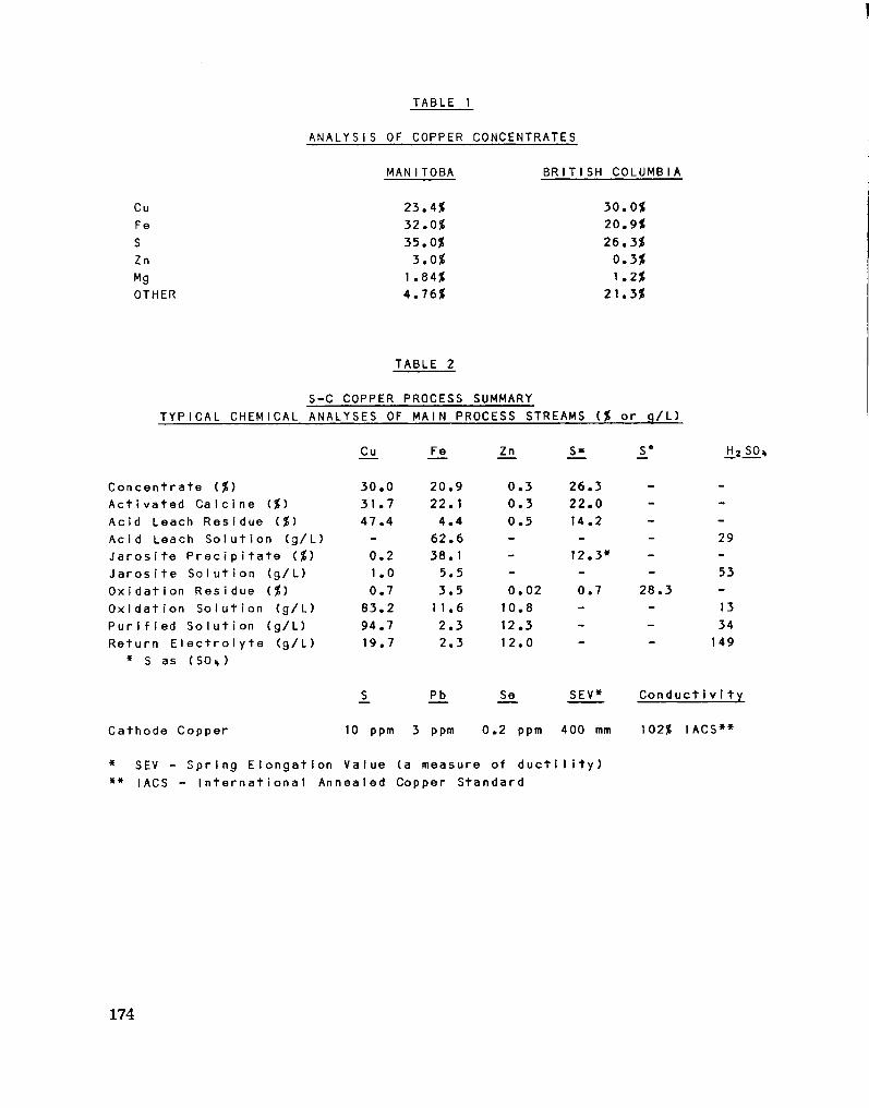
TABLE 1
ANALYSIS OF COPPER CONCENTRATES
MAN ITOBA BRITISH COLUMBIA
Cu Fe S Zn Mg OTHER
23.4$ 32.0$ 35.0$ 3.0$
1 .84$ 4.76$
30.0$ 20.9$ 26.3$ 0.3$ 1.2$
21.3$
TABLE 2
S-C COPPER PROCESS SUMMARY
Conc e n t r a t e ($) A c t i v a t e d C a l c i n e ($) Acid Leach Residue ($) Acid Leach S o l u t i o n (g/L) J a r o s i t e P r e c i p i t a t e ($) J a r o s i t e S o l u t i o n (g/L) O x i d a t i o n Residue ($) O x i d a t i o n S o l u t i o n (g/L) P u r i f i e d S o l u t i o n (g/L) Return E l e c t r o l y t e (g/L)
* S as (SO.,)
Cathode Copper
** IACS - I n t e r n a t i o n a
Cu Fe Zn S = S° H 2
30.0 20.9 0.3 26.3 - -31.7 22. 1 0.3 22.0 - -47.4 4.4 0.5 14.2 - -
- 62.6 - - - 29 0.2 38. 1 - 12.3* - -1.0 5.5 - - - 53 0.7 3.5 0.02 0.7 28.3 -
83.2 11.6 10.8 - - 13 94.7 2.3 12.3 - - 34 19.7 2.3 12.0 — 149
S_ Pb Se SEV* Conduct i v i t y
ppm 3 ppm 0.2 ppm 400 mm 1 02$ IACS**
1 ue (a measure of d u c t i 1 i t y ) 1 ed Copper Standard
174
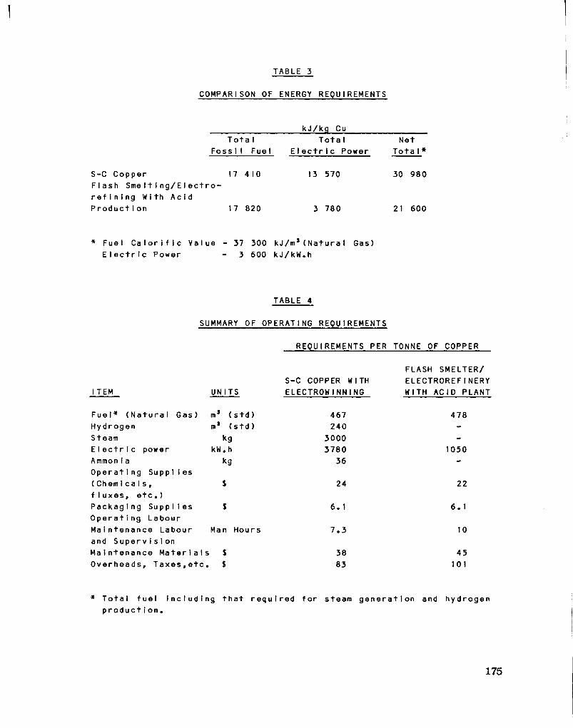
TABLE 3
COMPARISON OF ENERGY REQUIREMENTS
kJ/kg Cu Tota I
Foss iI Fue
S-C Copper 17 410 Fl a s h S m e l t i n g / E l e c t r o -r e f i n i n g W i th A c i d P r o d u c t i o n 17 820
Tota I E l e c t r i c Power
13 570
3 780
Net Tota I »
30 980
21 600
* Fuel C a l o r i f i c Value - 37 300 kJ/m s(NaturaI Gas) E l e c t r i c Power - 3 600 kJ/kW.h
TABLE 4
SUMMARY OF OPERATING REQUIREMENTS
REQUIREMENTS PER TONNE OF COPPER
I TEM UN ITS
F u e l * ( N a t u r a l Gas) Hydrogen Steam E I e c t r i c power Ammon i a Operat i ng SuppI Ies (Chem i ca I s , f I u x e s , e t c . ) Packag i ng SuppIi es Op e r a t i n g Labour Maintenance Labour and Superv i s i on Maintenance M a t e r i a l s Overheads, T a x e s , e t c .
ms ( s t d ) 3 ( s t d ) kg
kW.h kg
Man Hours
$ $
S-C COPPER WITH ELECTROWINNING
467 240
3000 3780
36
24
6. 1
7.3
38 83
FLASH SMELTER/ ELECTROREFINERY WITH ACID PLANT
478
1050
22
6.1
10
45 101
* T o t a l f u e l i n c l u d i n g t h a t r e q u i r e d f o r steam g e n e r a t i o n and hydrogen product i on.
175

TABLE 5
SUMMARY OF COST COMPARISON
S-COPPER WITH EW
200
I TEM
C a p i t a l Costs (M$) Working C a p i t a l D i f f e r e n c e (M$)
Op e r a t i n g Cost (^/kg/Cu) 40.6
FLASH SMELTER ELECTROREFINERY
WITH ACID PRODUCTION
246
+ 12.0
36.5
176

COPPER CONCENTRATE
tS
ACID PLANT
Ht 304 TO LEACH
CLAUS PLANT
•
CuS
BLEED TREATMENT
SOt ROASTER 1 TOP r
ROASTER 1 — 1
BOTTOM
F_UEL_
Ht
Ot NHI
3 £1 JAROSITE
PRECIPITATION
1 JAROSITE
Ht S04
OXIDATION LEACH
PRECIOUS METALS
RECOVERY
PM-CONCENTRATE
w r PURIFICATION
Ot
F « t 0 ,
S* AND TAILINGS
ELECTROWINNING GAS
LIQUID
SOLID
TAILINGS POND COPPER METAL
FIGURE i THE SHERRITT-COMINCO COPPER PROCESS SIMPLIFIED BLOCK FLOW DIAGRAM
177

3 C O H C I H T B a T f CLAIM KID
1 — *
T A T H E R M A L A C T I V A T I O N
A L A C I D L E A C H
B B L E E D
O L O X I D A T I O N L E A C H
P P U R I F I C A T I O N
EW E L E C T R O W I N N I N G
J A R O S I T E P R E C I P I T A T I O N
PMR P R E C I O U S M E T A L S R E C O V E R Y
cucnnoN cni I
umut w faiLHtu
M L T I N E M » r* U ! ' K 5
FIGURE 2
S-C COPPER PROCESS SCHEMATIC FLOW SHEET

C O P P E R C O N C E N T R A T E
A C I D P L A N T
R O A S T E R "LAIR OR ot
Hi 5 0 4 TO LEACH r
C L A U S P L A N T
T
R O A S T E R
B O T T O M
HtS
Hi S 0 4
Hs
4 4 A C I D
L E A C H
Ot NHS
'Jk £ 1 J A R O S I T E
P R E C I P I T A T I O N 1 CuS
o t i
3 i f Ht S04
J A R O S I T E
B L E E D T R E A T M E N T
OXIDATION L E A C H
P R E C I O U S M E T A L S
R E C O V E R Y
Ot
PM - C O N C E N T R A T E
S * A N D T A I L I N G S
ELECTROWINNING G A S
LIQUID
S O L I D
T A I L I N G S P O N D C O P P E R M E T A L
FIGURE 1 THE SHERRITT-COMINCO COPPER PROCESS SIMPLIFIED BLOCK FLOW DIAGRAM
177

SECTION VIII
HIGH EFFICIENCY SYSTEM FOR PYIOfETALLURGICAL RECOVERY OF HIGH-GRADE POPPER MATTE
FROM SULFIDE (mWSSAW
BY D. A. MACKIE P. PASCHEN G. MELCHER
179

INTRODUCTION
KHD, Kloeckner-Humboldt-Deutz, i s an engineering and manufacturing enterprise having i t s head office in Cologne, West Germany. Employee population i s in the range of 25,000 world-wide.
The Humboldt Wedag Division of KHD, with a world-wide employee population of about 5,000, i s the arm of the company involved with minerals processing. The company i s not a metals-producer, however, but i s engaged in direct selling of process technology, engineering, and equipment.
Principal factories are in Cologne and Bochim, West Germany. Fabrication of KHD designs i s often done local to the user, however, as dictated by economic and other conditions of convenience.
North America i s served ty KHD Canada, Inc., Montreal; and Deutz Corp. in the U.S.A. with offices in New York, Atlanta, and San Francisco. The Single Afachinery Division in Atlanta fabricates and assembles Humboldt Wedag designs.
HISTORICAL
Experiments with top-blowing of copper slag began in the laboratories in Cblogne, treating 4 kg. batches, more than seven years ago. The results of these bench-scale tests led to construction of a p i l o t unit in Cologne that was capable of performing tests on a discontinuous basis on 1,000 kg. batches, proving the elementary principles of the KHD Oontop (Continuous Top-blowing) process.
Two years ago, a continuous pilot unit was built in Bochim that was capable of smelting concentrates in a cyclone and treating slag ty the Cbntop process. Hie unit handled 1,000 kg per hour on a 24-hour-per-day basis.
ABSTRACT
This paper presents a discussion of the results of continuous autogenous smelting of sulfide concentrates and top-blowing in the p i l o t plant in Bochim, by using technical oxygen in a water-cooled
180
cyclone followed by treatment in a top-blown reacting vessel. The products are high-grade matte containing up to 80% copper and a slag with a fin a l copper content of less than 0.57.
A description of a proposed commercial-scale plant planned for a customer in South America i s given. The smelter i s designed to produce 15 000 tonnes per year of blister copper economically, which i l l u s trates the f e a s i b i l i t y of constructing small smelters directly at the mine site. The paper further describes the internal workings of a commercial sized cyclone smelting and Cbntop unit.
CYCLONE SMELTING
In pyrometallurgy, cyclones meet the requirements for intensifying significantly mass and heat transfer processes by the specific aerodynamics of a turbulent two-phase flow. The generation of high temperatures accelerates the rate of reaction. The specific thermal load i s by more than one decimal power higher than in conventional f i r i n g compartments:
About 30 GJ/ms/h against 1 to 3 GJ/m3/h. The specific smelting capacity too i s about 10 times higher than in classical metallurgical furnaces: 100 to 250 kg/m' /min against 2 to 50 kg/m'/nrim
KHP has acquired experience in construction and processing of cyclone furnaces for volatilizing antimony (1), treating residues from neutral zinc leaching (2), processing low-grade tin concentrate (3) and with the IvIVCET process (4-6).
In the test cyclone of our pilot plant, oxygen i s blown in tangent i a l ly. The solids are admitted either vertically or sucked in by oxygen from an injector, reaching the smelting compartment tangentially with the oxygen. Solids should be minus 3 mm in size and have a moisture content of 1% or less. The cyclone i s built on the so-called water-vox principle or as a waste heat boiler.
The f i r s t molten charge s o l i d i f i e s on the cold wall, thus creating a protective layer. The molten product i s discharged with the waste gas through the outlet opening in the cyclone bottom into a separating compartment.
181

This cyclone i s a smelting unit characterized by easy operation. If necessary, i t can be switched on and off within a few seconds. It does not require a specific mixture composition and handles most varying concentrates, either of pure or complex type. Changes in mixture composition can be performed without interruption of the process run. The same i s true as regards changes in the matte quality.
The unusual f l e x i b i l i t y of the cyclone i s shown in Figure 1. For instance, a cyclone designed for smelting 500 tonnes per day of concentrate to a matte of 60% copper can be operated autogenously between 70% and 110% of i t s rated throughput at uniform matte quality. An even wider range of the rated throughput i s possible by changing the matte quality. Similarly, the copper content in the matte can be varied between approximately 46% and 68% at an unchanged throughput of 500 tonnes per day.
A cyclone having a reacting vessel volume of no more than 1.6 ms
can be operated with a specific throughput of 350 t/ms/d. Copper mattes of 70% to 80% copper content have been smelted in the KHD test cyclone. Temperatures between 1800°C and 2000°C have been calculated for the cyclone on the basis of the thermal balance. In view of the fact that no solid magnetite i s stable at such high temperatures, the slag leaving the cyclone has a copper content of no more than 6% to 8%.
SLAG TREATMENT
Although the necessary slag treatment can be carried out by conventional methods, such as flotation or in an electric furnace, KHD consider these too costly and ineffective for a high-efficiency system and have developed the so-called 00NT0P process (continuous top blowing) for treating the slag after leaving the smelting cyclone. However, a O0FJTOP furnace could likewise be set up behind any other smelting furnace too.
For the OONTOP process a gas jet of high velocity i s blown on the melt.
182

In Figure 2 the jet pulse i s seen to change the shape of the bath surface deflecting the gas stream in such a way that i t causes rotation of the melt, whereby the reacting surface i s continually renewed.
For applications where not only a defined mass transfer but also a defined heat transfer i s of importance, as in the case of v o l a t i l i z a tion, for example, the high velocity gas jet can be enveloped by a slowly flowing heating gas jacket. Figure 3 shows this type of blowing lance where the reducing high-velocity gas jet i s surrounded hy several slowly flowing heating-gas streams. Figure 4 i s the continuation of the process towards the bottom. The strongly narrowed high-velocity gas jet impinges on the melt surface, changes the surface shape, and has the melt move.
It was investigated how the degree of oxidation of the slag, i.e. the Fe2+/j?e3+ ratio, which i s a measure of the slag f l u i d i t y , can be controlled by this top-blown process. Figure 7 shows that a conventional slag was f i r s t treated in an oxidizing atmosphere and the reaction gas jet then changed to a reducing atmosphere. This reducing treatment was continued until a Fe2+/Fe3+ ratio had been set that corresponded to the oxygen potential of the gas stream. Figure 8 shows the extraction of copper from the slag hy top-blown reducing gases.
The Fe'/Ite-tot ratio ascertained and the corresponding copper content of the slag as a function of the lambda figure of the reaction gas have been plotted in Figure 9. It turns out that the copper content of the slag f a l l s below 0.5% for lambda figures of less than 0.45.
PILOT PLANT
The KHD pilot plant in the Bochum works combined both methods, the cyclone smelting and the contop-blowing, to a high-efficiency system: Figure 10.
Concentrate and additives are fed into the cyclone (1) where they react with pure oxygen. The molten products are discharged with the waste gases downward into a settling chamber (2) where the three components are separated from each other. The slag i s transferred continuously into the CQNTOP reacting vessel (3) for reduction. The two furnace sections are separated by a partition vvall (8).
183
The lances had to be located parallel to the wall due to space limitations. The partition wall had to be incorporated as a guide element to make sure that the complete slag quantity passed successively underneath a l l three lances.
Table 1 specifies the results of the continuously operating pilot plant. At a throughput of 1 tph of concentrate containing 25% Cu, 30% Fe, and 33% S, 325 kg/h or matte of 72% Cu have been smelted at an oxygen consumption of 240 m2ph. The slag contained 1% of copper, that value however could have been lower with a larger settling area that had not been available due to lack of space. The copper content of the slag to be dumped can be reduced to minus 0.5% by enlarging the s e t t l ing zone.
PROPOSED 15 000 TONNES (XEWERCIAL-SIZED PLANT
Recently, KHD prepared a quotation for a commercial-sized plant for a customer in South America. This plant was designed to produce approximately 15 000 tonnes of blister copper: Figure 9. Moist f l o t a tion concentrate and the additives ground to minus 1 mm are fed continuously into a rotary dryer and dried to a residual moisture of 1%. Hot a i r discharged from the waste-gas cooler of the smelting furnace i s used for drying the concentrate. After the addition of recycled precipitated dust, the dried charge i s sent to the cyclone where i t i s oxidized with technically pure oxygen. The cyclone i s 1.0 m high and has a diameter of 0.8 m.
Although the structural design of the OONTOP furnace having a surface of 30 m2 in this plant differs in several details from the pil o t installation described, i t i s basically the same. An adequate stabilizing and settling zone has been provided between top-blowing lances and matte tapping.
The waste gas, which i s discharpod from the furnace jointly with the non-burned components of the reducing gas i s subjected to secondary combustion by admixing cold a i r . An indirect a i r cooler has been provided for cooling the waste gas. A waste heat boiler can be provided as well. The slag to be dumped i s allowed to leave the
184
furnace at the front side and i s then granulated. The iratte i s removed from the furnace through a siphon taphole and directed to the converting vessel through a launder; the converting vessel i s also operated by the top-blown process. It i s intended to use technically pure oxygen as an oxidation agent. The absence of nitrogen ballast w i l l enable the conversion of converting high-grade matte where oxidation and slagging of the iron has only l i t t l e influence on the thermal balance, without d i f f i c u l t i e s with respect to temperature control.
The waste gases discharged from the two furnaces are combined and contain approximately 43% SO*. They are subjected to dust collection in an electrostatic precipitator and are then sent to the sulfur ic-acid plant.
CALCULATED DATA FOR A 50 000 TONNES COMMERCIAL PLANT
Tables 2 and 3 quote the consumption and production figures per tonne of concentrate for the production of 50 000 tonnes anode copper.
The cost of investment including a l l steps from concentrate drying to cast anodes with buildings, c i v i l works, oxygen and sulfuric acid plant, erection cost and start-up wil l be in the order of 51,000.00 US per tonne yearly capacity.
Hence the combination of cyclone and top-blown technique permits a pronounced shift of the break-even point towards small annual capacit i e s . Consequently, the prospect of a smelter next to the mine should become feasible for the f i r s t time.
Figure 10 shows the new furnace combination.
SMELTING IN THE COMMERCIAL UNIT
After drying of the moist concentrate in a rotary dryer, i t i s stored in a bin, and transported via a i r l i f t to the feed hoppers, where the concentrate, together with quartz and technically pure oxygen i s delivered to the cyclone. Oxygen and concentrate are so well mixed together, that a concentrate in the cyclone containing as high as 79 -81% Cu could be smelted. In this manner, almost a l l of the iron and the sulfur i s oxidized in the cyclone. The heat released in the
185

process leads to a cyclone furnace chamber load of more than 21 million KJ/m3/h. Gas and fused mass reach a temperature of over 2100° C. This temperature, however, i s too high for the brick lining. Cooling of the gas/fused mass mixture in the cyclone i s necessary.
In the pilot plant, i t proved to be practical to keep the fused mass/gas mixture at a temperature of approximately 1600°-1700°C at the discharge from the smelting cyclone. This was done by water-cooling the cyclone. A practical method would be to use the cyclone as a boiler. Meta1lurgically, the high temperature inside the cyclone produces greatly improved thermodynamic conditions for the smelting process, so that a high volatilization of the lead, zinc, and arsenic contained in the concentrate takes place.
SEPARATION OF GAS AND FUSED MASS
The fused mixture and gas are separated in the furnace chamber of the primary smelting chamber under the smelting cyclone. The hot smelted mLxure i s collected on the floor of the collecting shell and flows into the slag treatment chamber.
SLAG TREATMENT AND REMOVAL OF ODPPER MATTE
The slag treatment i s conveyed through water-cooled oxygen lances to the slag tank surface ty the introduction of reducing gases (2). This reduction operation works in 3 ways:
(1) Reduction of the magnetite s t i l l existing in the slag from approximately 10% to 2% with a velocity of k - 8 x 10""/sec.
(2) The remaining reducing volatilization of zinc, and
(3) The remaining volatilization of lead sulfide and lead oxide.
After the reduction, the disposed slag shows a composition of:
CaO FeO PesO-SiO*
5.0% 60.0% 2.0%
28.4%
186
AlaOs 2.5% Zn° 1.5% Cu 0.6%
For control of this slag, no lime admixture i s necessary unless some s i l i c a i s added. This slag shows a viscosity of below 0.5 P at a cut-off temperature of approximately 1350°C and under those conditions i s best suited for disposal of granulated slag. The matte has a composition of approximately 81% CU, as well as 0.4% Fe and sulfur as the balance. Hie waste gases from the cyclone and the slag treatment are conducted out of the hearth oven. At a temperature of approximately 1400°C, the waste gas shows a composition of:
10% CO 2% Hz 6% H2O
72% SO2
5% N2
5% Zn
For smelting capacity of 500 tonnes concentrate per day, the cyclone has an inside height of approximately 2.2 m and a diameter of 1.6 m. The primary smelting chamber dimensions underneath the cyclone are 13 m by 6 m, inside. The inside height of the primary smelting chamber i s 3.2 m at the vortex. The number of lances for the slag reduction i s 10.
CONVERSION AND REFINING
The copper matte flows continuously through a launder to a closed trough in the converting and refining oven (3). At approximately 1350°C, the temperature of the matte i s so high that an additional heating of the closed trough i s not necessary. Referring to Figure 13, furnace chamber 3a has a hearth area of 12 m2, where the white metal i s blown into blister copper ty the blowing of an air-oxygen mixture. Because of the small iron content, no formation of slag takes place in the white metal. For the most part, the small iron mass as well as the existing zinc and lead are volatilized due to the high temperature in the dimple; a small amount remains in the refined copper. 12 lances are needed for the conversion and oxidation work. The conversion
187

process i s conducted in such a way that the stationary copper mass in the conversion chamber shows an oxygen content of over 1%, and the white metal flowing in sometimes reacts directly with oxygen gas, but sometimes reacts with the oxygen released from the copper. In connection with the conversion work, a further oxidation of the copper to 1.5% O2 takes place in the oxidation chamber (3b). Through blowing of the reduction gases in the reduction chamber (3c), the oxygen content i s lowered to 0.2% O2 i n copper. Total lances are 12. The reduction constant k for the Oa-reduction i s k - 2 x 10" * /sec. The hearth area needed for the reduction i s 14 m2.
The expected copper yield in the anode furnace i s 98.8%.
ACKNOWLEDGEMENT
Hie authors would like to thank the German Federal Ministry for Research and Technology for the financial promotion of the tests carried out for slag treating.
REFERENCES
(1) E. Mueller: Die Verfluechtigung von Antimon aus sulfidischen Vorstoffen im Zyklonofen; Erzmetall 31 (1978) 267-275.
(2) R. Nissen, I. Lema-Patino: Die Verarbeitung von Zink-Neutrallaugungsrueckstaenden im Schmelzzyklon; Vbrtrag auf der GEMB-Hauptversammlung in Innsbruck, Mai 1978.
(3) E. Mueller: Verfluechtigung von Zinn aus armen schwefel-haltigen Konzentraten in Zyklonofen; Erzmetall 30 (1977) 54-60.
(4) N.N.: Kivcet Process for complex ores offered to western smelters; World MLn. (1974) June 26-27.
(5) G. Melcher, E. Mueller, H. Weigel: Ehtwicklung, Grundlagen und Anwendung des Kivcet-Zyklonschmelzverfahrens mit reinem Sauerstof f fuer verunreinigte Kupfererze; Erzmetall 28 (1975) 313-322.
(6) -, -: The Kivcet cyclone anelting process for impure copper concentrates; JOM (1976) July, 4-8.
188

(7) F. Sauert et a l . : High-efficiency system for pyrometal lurgical recovery of high-grade copper matte from sulfide concentrate; Erzmetall 33 (1980) 371-377.
189

TABLE 1
PI LOT PLANT TEST DATA
Input Output
C o n c e n t r a t e 1000 kg/h Matte 325 kg/h - Cu 25 % - Cu 72 % - Fe 30% - Fe 5 % - S 33% Slag 660 kg/h S i 1 i ca 110 kg/h - Cu 1 % L i mestone 60 kg/h - Fe 43 % Oxygen-cyclone 240 m'/h* - S i 0 2 28 % Propane 26 m3/h* - CaO 9 % Oxygen-Contop 64 m'/h* Cyclone dust 48 kg/h
- Cu 13 % Cyclone waste gas 270 m'/h -S0 2 67 % Contop dust 7 kg/h Contop waste gas 200 m'/h
standard s t a t e
190

TABLE 2
CONTOP FURNACE OPERATING DATA
Co n c e n t r a t e A n a l y s i s
Cu 23.5$ Fe 30.7$ S 32.0$ S i 0 2 5.2$ CaO 0.9$
Feed
C o n c e n t r a t e S i l i c a Sand LImestone Oxygen, 95$ 0 2
Propane
Output
Matte 58 TPD Slag 129 TPD Off g a s 215 Nms/T 1,2)
1) As mixed 2) Before a f t e r b u r n i n g
182 TPD 29 TPD 18 TPD
215 Nms/T 7 NmJ/T
1) 1 )
191

TABLE 3
CONSUMPTION AND PRODUCTION FIGURES PER TON CONCENTRATE FOR THE PRODUCTION OF ANODE COPPER
S i 1 i ca 127 kg LImestone -Oxygen 317 Nm9
Natural gas 37 Nms
Matte (81$ Cu; 0.4$ Fe; Rest S) 345 kg C y c l o n e - s l a g (61$ FeO; 2$ FesO*, 28$ Si 0 2 ; 6$ CaO; 0.5$ Cu) 532 kg
C o n v e r t e r s l a g -Slag anode r e f i n i n g (20$ Cu) 12 kg Waste gas c y c l o n e - c o n v e r t i n g r e a c t o r (43$ SO2) 550 Nm3
Steam P r o d u c t i o n (43 Bar, 300°C) 4500 kg
192

FIG. I Operating range of a cyc lone.
193

High velocity oxygen jet stream
Metal or matte r
J v . . j
FIG. Z Top blowing system for recovery of metal values from slag.
194
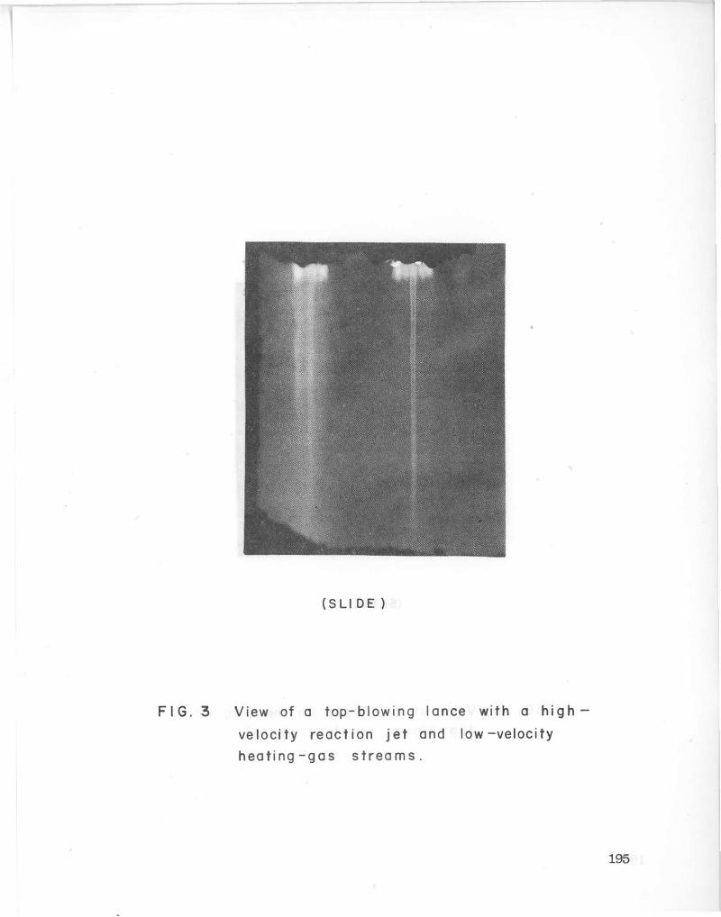
(SLI D E )
F I G . 3 View of a top-blowing lance with a high -velocity react ion jet and low-veloci ty hea t i ng - gas s t r e a m s .
195

(SL IDE)
F I G . 4 View of a d imple in the s lag in a t o p - b l o w n reac t ing v e s s e l .
196
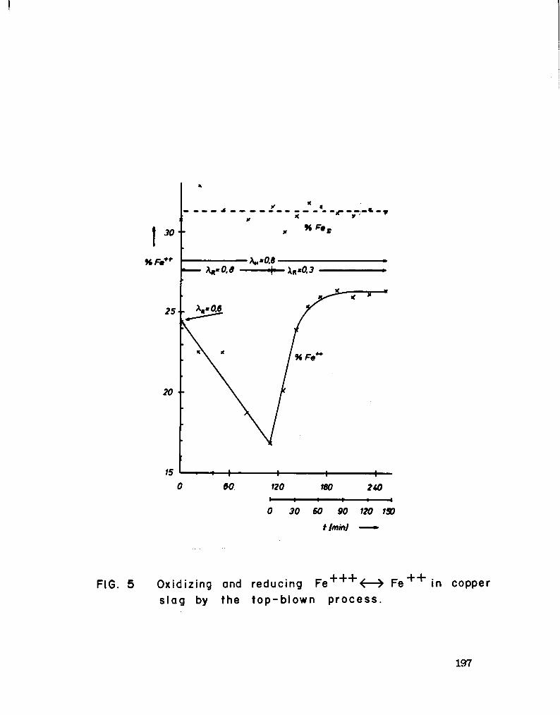
60 120 180 2W
0 30 60 90 120 150
t Imml •
FIG. 5 Oxidizing and reducing Fe + + + <—> F e + + i n copper slag by the top-blown process.
197

0.0 0 60 120 180 240 300 360
t ( m i n i — »
FIG. 6 Copper content in Slag when reducing by the top blowing technique.
198
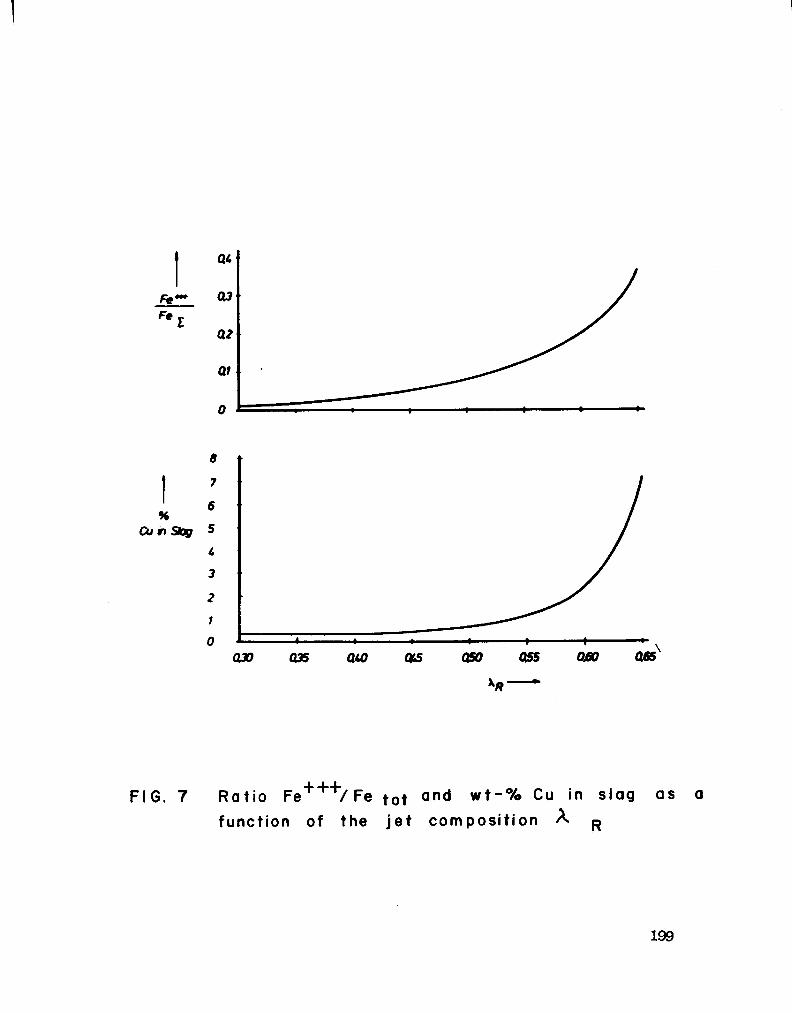
199

c*Ha
sue MATTE
1. Cyclone 2. Settling chamber J Top - Blowing - Reactor 4 After burning chamber
5. Cooler 6. Bag house 7. Multi - Cyclone 6. Partition mi
FIG. 8 Pi lot Plant Cyclone furnace with top-blown reacting vesse I.
200

201

12
FIG.IO Section through a Commercial Cyclone-ConTop Unit.

SECTION IX
TOP BLOWN ROTARY CONVERTER (TBRC™) PROCESS FOR NON-FERROUS SMELTING, Q-5 ONGW PftX^.CKY&EN SPRINKLE
P&OCESS
BY R.A. DANIELE
203

Richard A. Daniele Manager, Pyrometallurgy Dravo Engineers & Constructors
Denver, Colorado
INTRODUCTION
Three copper smelting processes are discussed in this paper:
(1) TBRC™ Process* (2) Q-S Process (3) Oxygen Sprinkle Staelting Process
The TBRC process i s currently available technology. It i s u t i l ized in the f i r s t copper anelter in modern times in British Cblumbia. The Afton Mines Ltd. smelter i s located 16 KM west of Kamloops, B.C.
The Q-S process i s one to be considered in the long term. It i s a single vessel, continuous process, for the late 1980's.
The Oxygen Sprinkle anelting process has been devised to transform existing reverberatory furnaces to oxygen flash smelting units. Although i t does not have application in B.C., i t i s presented in the context of a step along the way in the development of the Q-S process.
TBRC™ PROCESS
The TBRC™ Process for non-ferrous smelting i s an amalgamation of mechanical equipment and process tehnology. Both are evolving and improving since i t s f i r s t use for nickel in 1972. The result i s a stirred reactor providing rapid mixing for high reaction rates and high heat transfer rates in a controlled atmosphere.
* Dravo Corp. i s the worldwide licencee from Inco Metals Co. for tlie TBRC for treating copper materials.
204

MECHANICAL EQUIPMENT
Figure 1, TBRC Arrangement, i s a cross-sectional view of the TBRC. It i s basically a refractory lined vessel encased in a steel shell. Attached to the steel shell are cast steel track rings. The track rings and shell are supported in a vessel support frame. Within the frame, motor-driven support rollers are held. These driven rollers, two pair on each side of the vessel, then rotate the cast steel track rings. The TBRC vessel rotates at inf i n i t e l y variable speeds from 0 to 40 REM. The support also has a thrust r o l l e r to take the downward load from the furnace.
A t i g h t - f i t t i n g hood, which i s designed to minimize inleakage of ambient air, closes over the vessel mouth against a sealing ring. It has a water-cooled charging chute, and water-cooled process lance.
The equipment i s a key part of this process. The following are a few of the steps in the continual development of vessel improvements as used for non-ferrous processing. The f i r s t vessels at INCXVs Copper C l i f f f a c i l i t y had the cast steel running rings welded to the steel shell. These vessels also had f l a t bottoms. The f l a t bottom, which i s removable, has never been removed. The original idea of the removable bottom was to make i t easier to replace the refractory. As i t was never used, this particular feature has been eliminated in more recent models. Hie second generation units were installed in Indonesia and Afton Mines Ltd. represents the third generation.
One of the changes to note in the third generation vessel i s that the f l a t bottom i s no longer used. It has been replaced with a dished bottom, which gives higher strength at lower cost. The vessel support system i s somewhat different than the previous ones in that i t i s less bulky. Another item of note i s the attachment of the running rings to the steel sheel. No longer are they welded to the shell, but are now attached through 12 pins and a set of springs. These advances, like a l l technology, are oriented toward solving the problems that have occurred in the past. Each new unit has less problems than the previous ones.
The entire vessel i s supported on concrete pedestals through trunnions and pedestal supports. A spur gear rotates the vessel through 360° in either direction.
205

PROCESS TEOTOJOGY
The second part of the amalgamation in the TBRC™ Process i s the process technology. This technology i s attributed to three key features.
(1) Atmosphere Control
(2) Temperature Control x
(3) Turbulence Control
Atmosphere control i s obtained in several manners. F i r s t , the process lance i s a surface blown lance. It i s not submerged below the bath; therefore, i t allows the use of high levels of oxygen without the problems of deterioration due to temperatures such as one would experience in the Pierce-Smith converter. The TBRC hood with the process lance and the charging chute, both of which are water-cooled closes over the vessel mouth. The atmosphere inside the vessel can be oxidizing, reducing, or neutral. This f l e x i b i l i t y eliminates sulfur and iron when oxidizing, decomposes copper oxide when reducing and v o l a t i l izes impurities when neutral atmospheres are used. The atmosphere features provide a degree of f l e x i b i l i t y in processing not readily available in other equipment.
Table 1 reflects an example of impurity elimination. This table reflects the f u l l scale testwork on Craigmont, B.C. concentrate performed at the INCO TBRC f a c i l i t y in Copper C l i f f , Ontario. Although the quantity of these metals: arsenic, lead, bismuth and selenium are very low, the TBRC s t i l l did an excellent job removing them. Over 90% of the arsenic, and the lead, and over 38% of the bismuth and the selenium were removed between concentrate and blister copper. The best eliminations are obtained at temperatures controlled above 2500°F and at high RPM.
Another feature of the TORC™ Process i s selective converting. That i s the ab i l i t y to have a liquid/liquid extraction of precious metals from a molten copper sulfide phase into a phase. Basically, when the finish blow begins in the converting cycle with copper
206

!
sulfide, 10-15% of the copper sulfide i s oxidized to copper metal. At that point, using a neutral or slightly oxidizing atmosphere, the vessel i s rotated at high speed.
The copper in this liquid-liquid mixing of sulfide and metal phases extracts the precious metals from the copper sulfide phase. This high grade precious metal copper could be removed and sent to an electrolytic refinery for further processing. The remaining copper sulfide could be converted into a fire-refined copper and marketed directly.
In summary, atmosphere control, i s the result of being able to surface blow and adjust the oxidizing, reducing and neutral conditions inside the TBRC vessel.
The second key feature i s temperature control. A l l of these features overlap to a great degree. The temperature can be controlled by blowing oxidizing gases from air to oxygen; by oxy-fuel combustion; and ty keeping refractory bath and atmosphere in equilibrium. The correlation between temperature in the molten bath and refractory i s very close. Use of optical and immersion pyrometers to check the bath and refractory wall temperatures has shown that the temperature of both correlate within 10°F. This permits the use of optical pyrometers to check the process temperatures.
For oxy-fuel combustion the TBRC has the a b i l i t y to barn natural gas or liquid fuel. This i s primarily for smelting but raising the temperature of the bath i s advantageous, for example, in impurity elimination.
Temperature i s also controlled through exothermic heat generation control, in particular the burning of sulfur and iron in the material charged. The ab i l i t y to blow a f u l l range of oxygen levels as opposed to air or slightly enriched oxygen in conventional equipment allows the TBPC to operate at predetermined temperatures. One of the most recent advances in the TBRC process development has been the application of the flash smelting technique to the TBRC. This was piloted at the Port Colborne test f a c i l i t y of PKX). This work, "Flash Smelting in a Converter," by Dr. fclalcolm Bell was published in the Journal of Metals in 1978. This allows the TRRC the a b i l i t y to produce controllable matte grades and clean slag similar to the INOO flash furnace.
207

A third item on temperature i s the refractory-bath-atmosphere equilibrium. Along with being controlled, the rotation of the vessel brings both the bath and the refractory into temperature equilibrium. Rotation also allows the phases to be mixed in the vessel. During the copper blow there i s a thin layer of residual slag, white metal (CtuS),and the copper. As the vessel rotates, droplets are carried up the side of the vessel and f a l l through the gaseous atmosphere. This then permits control of oxidation rates to a much higher level than i f gases were bubbled through the bath. This gives good contact between the phases. Hie phases, due to different densities, move at different rates therefore the reaction point i s concentrated at the phase interface.
In summary, temperature i s controlled through either oxy-fuel combustion, exothermic heat generation, or transmittal through refractory into the bath by the atmosphere equilibrium.
The third key feature i s turbulence. Turbulence i s controlled ty both the variable speed of the vessel and process lance penetration. Rotational speeds are selected depending on the chemical process reaction desired. During charging, relatively low speeds are used. Diring de-oxidation, when copper reduction i s required, high speeds are used. In addition when the constituents to be reacted are present in low
concentrations, the high speed allows these to react at faster than conventional process rates, e.g. up to 40 RPM. There are virtually no emissions into the work environment when the process i s being carried on even at high RFM.
The other item affecting turbulence i s the lance jetting. The process lance releases i t s gaseous products at speeds greater than Ma.cn 1. It i s these high velocities which result in bath penetration. This penetration creates waves which add to the rotational turbulence.
In summary, turbulence i s effected by both lance jetting and va r i able speed rotation.
Mien analyzing the TBRC processing capability and i t s a b i l i t y to control these key features: atmosphere, temperature, and turbulence,
208

the result i s a capability not obtained in conventional equipment. It's reflected in Figure 2 which i s a graph of "copper in slag" versus the "percent copper in the matte". Due to the high reaction rate a b i l i t y of the TBRC, i t i s possible to shift the normal curve where in the slag an increase in copper matte grade results in a related in copper slag. The shaded area represents the matte slag area during the i n i t i a l full-scale testing of the TBRC™ at INOO.
In order to develop the process parameters of the Afton 'tines Ltd. f a c i l i t y , pilot plant work was undertaken at Port Cblborne. Oie of the items in the pilot plant effort was the determination of the slag cleaning a b i l i t y in the TBRC™. Four tests demonstrated the a b i l i t y of the TBRC to clean slags. Typical values were: 67% copper in the matte, 0.65% copper in the slag; 78% copper in the matte and 1.2% copper in the slag.
At Afton one of trie key elements of the TBRC process i s that i t made a mini-smelter possible. Historically, i t has been a general concept that smelters had to be large tonnage f a c i l i t i e s to be economica l . With the advent of the TBRC™, single vessel mini-smelters were technically, environmentally, and economically possible. A smelter can be built to treat as l i t t l e as 100 tonnes per day concentrate, or 8-10 000 tonnes per year copper economically, using a single vessel. \t Afton Mines Ltd. the TBRC process provides an excellent method by which relatively small quantities of concentrates are treated; however, the design of a mini-smelter must incorporate innovative equipment not common to industry in order to maximize vessel availability and minimize cost.
Work area emissions are a very important item. Ttiese are controlled by a hood which covers the vessel mouth with a flexible seal. Inleakage into the process off-gas system i s controlled through pressure measuring devices on the hood. This plays a key part in the off-gas cleaning system. Off-gases, and cost of off-gas cleaning, i s a function of the volume; by minimizing leakage, the volume i s kept to a minimum. The more concentrated SO2 i s in the off-gas, the easier i t i s to f i x . This type of hood design permits this capability. The entire TBRC™ area i s enclosed in a hood which i s ventilated. The TBRC™, when the process hood i s open, produces a small i n i t i a l
209

puff of emission as the vessel comes to equilibrium with trie ambient pressure. Beyond that, there i s very l i t t l e emission. This i s an important environmental consideration when using the TBRC™.
Normally not included in smelters are large slag recovery hoods, which collect the fugitive emissions. At Afton, the fugitive emissions are not scrubbed as the 302 concentrations are relatively low.
Another item i s the use of a concrete converter aisle. Old time copper operators w i l l shudder at the thought, but after 2 1/2 years of operation, although i t doesn't look brand new, there are very few s p i l l marks, and a power sweeper i s able to keep the convertor aisle clean. This keeps down in-plant particulate emission and i t also encourages operators to be far more careful than they might normally be with the typical d i r t floor in a copper converter aisle.
In a modern smelter, material balance control i s a very important item. Most plants weigh the charge to the smelter and weigh the copper out the door, but few weigh the intermediate products. At Afton the ladles are weighed on a platform scale and these weights are used to keep both copper and slag material balances. Copper weighed out the door i s trie f i n a l product, but there are always recycle products; weighing permits the operators to monitor the difference between copper out of the TBRC and copper which goes to market.
Another key item in the mini-smelter i s the type of crane which i s chosen. The typical smelter crane i s a two-girder crane. It consists of the main hoist and two auxiliary hoists. The weakness of this type of system i s that the access of the train hoist to, the edge of the converter aisle i s limited by the width of the auxiliary hoists. In order to minimize this, two main hoists have been used. This in fact does cut down the distance or improve the approach. However, main hoist speeds are 30-70 feet per minute about 1/3 or 1/4 of auxiliary hoists. This slows down the operation. The crane at Afton which i s the f i r s t application in North America, i s a four-girder crane. A four-girder crane offers both operating and economic advantages. Its difference l i e s in that the auxiliary hoist travels on i t s own pair of girders; the main hoist on a separate pair, hence four-girder crane. The auxiliary hoist travelling on separate girders; lias the a b i l i t y to make very close approaches to either side of the main hook, no
210

matter how close the main hook comes to the converter aisle edge. The economic advantages l i e in that, because closer approaches are made, capital costs of cranes are less, because cranes are priced more on span than on capacity. The other item affecting operating costs i s that four-girder cranes, historically a normal item in a steel m i l l , have much higher r e l i a b i l i t y than typical copper smelter cranes.
Another innovation which also affects capital costs i s the use of the slide gate valve. The valve i s hydraulically operated and can be opened at any degree from f u l l closed to f u l l open. The ladles used at Afton Mines are heated refractory lined ladles. In order to minimize plugging of the o r i f i c e for the slide gate valve, s i l i c a sand i s poured down into the valve nozzle area; when the valve i s opened there i s a flow of the s i l i c a sand followed by the molten copper.
The ladle i s used instead of a holding furnace after being heated and supported on a casting stand with a cover. In-plant fugitive emissions are cut in half, because molten copper transfers are now reduced to one, rather than two.
In a TBRC™ copper smelter, smelting, converting, and ref i n ing, are performed in a single vessel. To man the TBRC requires one operator and one helper.
Process gases go from the cooler to an electrostatic precipitator and then to the dual al k a l i scrubbing system, which Afton Mines u t i l izes to control a l l SO2 emission. The cleaned process gas stream passes into a venturi, a tray tower SO2 and then off to reheating and to a stack. The scrubbing i s accomplished through a dual a l k a l i system. Regenerated solution, a mixture of sodium s u l f i t e and caust i c , i s pumped to the venturi and down the tray tower, the solution after stripping the SO2 from the process off-gas stream, i s collected in a spent solution tank. The spent liquor i s regenerated by reacting with mild of lime solution, removing the sulfur dioxide as calcium sulfide crystals, which are settled in a thickener. The pulp i s fil t e r e d for additional water removal and recovery of the scrubbing agent. The solution i s then returned to the regenerated liquor storage for use on the next cycle. The sludges are then sent to the tailings pond. At Afton less than 100 TPD of sludge, i s mixed with 7,000 TFD of tailings. The use of a fiberglass stack reduced the cost to one quarter the cost of a concrete stack.
211

In large tonnage f a c i l i t i e s , instead of using one vessel for smelting, converting and refining, i t i s preferable to have a primary smelting furnace and then use the TBRC as a converter.
In light of the development of small high grade or remote mineral deposits, local highly efficient mini-smelters become increasingly attractive. Local populations may be more willing to accept a small integrated smelter rather than a large central smelter. The v e r s a t i l i t y of TBRC for both a process and an environmental control offers a viable alternative to the Pierce-Smith converter and anode furnace when used in conjunction with large primary smelting furnaces.
The QS oxygen process i s an attempt to reach that 'will of the wisp' panacea of a smelting process, with the entire process being conducted in a single vessel. The process advantages of the QS as proposed, offer single vessel steady-state conditions, countercurrent flow of matte and slag, staging of oxygen ac t i v i t i e s , temperature control, and shielded submerged tuyeres. The accomplishment of this objective i s done in the QS oxygen reactor, which i s approximately 20' dia. x 150' long, at a 1° slope. Concentrate i s charged to the QS reactor via vortex burners which smelt concentrate with oxygen, and produces a matte. Subsequently, a i r i s blown into the matte through shielded tuyeres. Hie matte flows counter-current to the slag and, prior to discharge, coal, SO2, nitrogen and/or oxygen are injected through a shielded tuyere to lower the oxygen activity of the QS process.
One of the problems with large innovative processes i s the large sum of money they take to develop. In order to minimize these expenditures, an innovation which i s directly applicable today to existing reverberatory furnaces i s the Oxygen Sprinkle Smelting furnace. Hie Oxygen Sprinkle anelting furnace i s an outgrowth of a need to develop the vortex burner for QS and what has transpired i s the development of an oxygen sprinkler burner which i s designed to mix oxygen and concentrate, and ignite them inside the reverberatory furnace. Hie key to this i s the a b i l i t y of the sprinkler burner to provide a very broad horizontal distribution within a very short vertical height. This transforms the reverberatory furnace into an oxygen flash smelting
212

reactor. In addition to making i t an oxygen smelting reactor, the addition of lower grade concentrate coal and oxygen at the fourth sprinkler turner towards the slag skimming end, reduces the oxygen activ i t y of the slag in that area ty sprinkling low grade matte on the surface of the slag, washing the slag and producing potentially much lower copper in slag. Hie advantages of this process are that i t can salvage the reverberatory furnace. To replace an existing reverberatory operation with one of the new efficient flash smelting type furnaces i s a pretty costly item, whereas the conversion of an existing reverberatory to an Oxygen Sprinkle Smelting furnace costs 5-7 million dollars. The largest portion i s for the f l u i d bed dryer, because as in a l l flash smelting processes, the material must be dried to less than 1%.
A second advantage i s that i t increases the SO2 concentration. The reverberatory furnace, by use of oxygen has reduced gas volume and increased SO2 concentration which permits the gases to go to an acia plant.
The third advantage i s the greater throughput; the sprinkler burner can smelt at rates up to 450 TPD which, using four burners, amounts to 1350 STPD.
Fourth, by adjusting the oxygen concentrate ratio to the various burners, the matte grade can be controlled. Hie matte grade at the f i r s t burner could be controlled at 65% copper, the second burner 55% copper; the third burner would then produce a 45% matte, and the fourth burner would be a 30% matte. Hie net effect would be a 50-55% copper matte as a product of the furnace.
The f i f t h advantage i s a potential for less copper in the slag due to the cleaning of the slag ty the low-grade goal concen crate smelting burner, and reduction in the oxygen activity of the slag.
A l i s t of papers referenced follows.
213

REFERENCE PAPERS
(1) FULL SCALE TBRC SMELTING TESTS ON COPPER CONCENTRATE by P.A. Daniele and L.H. Jaquay, Dravo Corporation, Pittsburgh, Pa. Presented at 1974 AIME Annual Meeting.
(2) TBRC - A TOT SMELTING TECHNIQUE by R.A. Daniele and L.H. Jaquay, Dravo Corporation, Pittsburgh, Fa. Presented at 1972 AIME Annual Meeting.
(3) THE Q-S OXYGEN PROCESS by P.E. Queneau, Thayer School of Engineering, Dartmouth College, Hanover, New Hampshire and R. Schumann, Jr., School of Materials Engineering, Purdue Universit y , West Lafayette, Indiana Reprinted from the Journal of Metals, August 1974.
(4) METAT/10RPH0SIS OF THE COPPER REVERBERATORY FURNACE: OXYGEN SPRINKLE SMELTING by Raul Etienne Queneau, Thayer School of Engineering, Dartmouth College, Hanover, New Hampshire and R. Schuhmann, Jr., School of Materials Engineering, Airdue University, West Lafayette, Indiana Reprinted from Journal of Metals, Vol. 31, No.12, December 1979, pp. 12-15.
214

TABLE 1
ELIMINATION OF IMPURITIES
ARSENIC Assay
% % of
Tota I
LEAD B I SMUTH As sa y
% % of
Tota I Assay
% % of
TotaI *
SELENIUM Assay
% % of
Tota I
C o n c e n t r a t e .0057 - .0027 Slag .0013 14.8 .0015 35.8 B l i s t e r Copper .0020 8.7 .0010 9.0 Dust .0300 65.9 .0110 50.3
.0005
.0001
.0002
.0016
13.2 10.3 39.7
.013
.001
.006 ND
5 1 1.3
Due to the d i f f i c u l t y of measuring these low c o n c e n t r a t i o n s . It was not p o s s i b l e to account f o r a l l the blsmuth.

FIGURE I
TBRC ARRANGEMENT
216
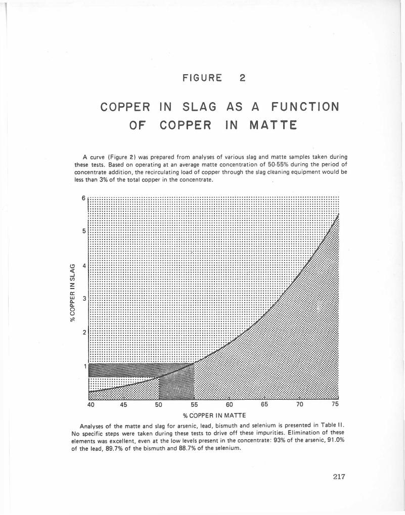
FIGURE 2
C O P P E R IN S L A G A S A F U N C T I O N
O F C O P P E R IN M A T T E
A curve (Figure 2) was prepared from analyses of various slag and matte samples taken during these tests. Based on operating at an average matte concentration of 50-55% during the period of concentrate addit ion, the recirculating load of copper through the slag cleaning equipment would be less than 3% of the total copper in the concentrate.
< — i if)
LU Q. 0. o o
40 45 50 55 60 65 70 75
% C O P P E R IN M A T T E
Analyses of the matte and slag for arsenic, lead, bismuth and selenium is presented in Table II. No specific steps were taken during these tests to drive off these impurities. El iminat ion of these elements was excellent, even at the low levels present in the concentrate: 93% of the arsenic, 91.0% of the lead, 89.7% of the bismuth and 88.7% of the selenium.
217

SECTION X
OVERVIEW ON COPPER EXTRACTION TECHNOLOGY FOR BRITISH COLUMBIA
BY W.J.S. CRAIGEN
219

1
OVERVIEW CN COPPER EXTRACTION TECHNOLOGY FOR BRITISH COLUMBIA
W.J.S. Craigen CANMET
Dept. of Energy, Mines and Resources Canada
For Presentation at Br i t i s h Cblumbia Copper Smelting and Refining
Technologies Seminar
Organized by the B.C. Ministry of Energy, Mines and Petroleum Resources
November 5 - 6 , 1980 Hotel Vancouver Vancouver, B.C.
220

SUMMARY
This overview i s an attempt to document on a comparable basis the relative merits of various copper smelting/refining processes, with special emphasis on factors relevant to a B r i t i s h Cblumbia location.
From an industry point of view, return on investment, which usually can be related directly to capital and operating costs, i s nearly always the most important criterion for evaluating processes and making investment decisions, with higher risk technology usually requiring a higher return on investment. However, from a government viewpoint, be i t federal or provincial, factors related to environmental impact, efficiency of resource recovery, energy type and e f f i ciency, plant location, employment and potential long term benefits are often of equal or greater concern than those related to the economics of the process. These factors are given due consideration in this assessment of the alternatives for the further processing of copper in B.C., so that hopefully conclusions and recommendations can be made that w i l l f a c i l i t a t e the efficient recovery and marketing of a valuable resource, while reflecting the needs and desires of both government and industry.

INTRODUCTION
Ibis overview was prepared at the request of the B.C. Ministry of Energy, Mines and Petroleum Resources. It i s intended primarily to document the major factors which affect the selection of appropriate copper extraction technology for B.C., and to offer some suggestions on how government and industry can inter-act to promote the development of the most desirable technology.
F i r s t , I would like to congratulate Frank Easham and his associates in the Ministry for their excellent efforts in organizing this very useful and well attended Seminar. I would also like to thank Frank for this opportunity to say a few words here today. Ottawa and Vancouver, as you know, are far apart geographically and sometimes even further apart p o l i t i c a l l y , so I'm sure you w i l l a l l be gratified to know that cooperation at the working level between our respective departments, at least with respect to minerals has never been better, and I certainly intend to do everything I can to maintain this close co-operation, which I believe i s essential to f a c i l i t a t e the expansion of the mineral industry in B.C.
We have heard some excellent presentations over the past two days on copper extraction processes which could have special application for a B.C. location. We are are perhaps fortunate, in this day and age, in having so many options to choose from. However, having so many choices obviously makes the evaluation and selection task more d i f f i c u l t and time-consuming. This overview therefore i s certainly not intended to be an in-depth evaluation of the various process options, but rather an attempt to document on a comparable basis the relative merits of copper extraction processes, with special emphasis on factors relevant to a B.C. location.
As a basis for comparison of the various process alternatives, five c r i t e r i a have been chosen which i t was f e l t would reflect the major concerns of both government and industry in the selection of appropriate copper extraction technology. These c r i t e r i a are listed, not in order of priority, but rather in order of increasing complexity. The c r i t e r i a are:
222

- Efficiency of Resource Recovery Plant Size Considerations
- Environmental Considerations - Energy Type and Efficiency
Capital and Operating Costs
In this overview I w i l l attempt to deal individually with each criterion, although obviously there w i l l be some overlap and the importance of each criterion to the overall process evaluation w i l l be very dependent upon other factors such as the characteristics of ore and concentrate, the location of the processing plant, by-product marketing problems, etc.
EFFICIENCY OF RESOURCE RECOVERY
B.C.'s present production of copper concentrates amounts to about 340 000 tons per year of contained copper. Most of this i s recovered from porphyry type ores containing less than 0.5% copper. The copper concentrates produced average about 29.5% copper, with recoveries from the ore averaging about 86%. For most producing mines the recovery of copper from these low-grade ores i s reasonably good, and i t i s unlikely that significant improvements in copper recovery can be realized economically. However, there are significant quantities of gold, s i l v e r and often molybdenum associated with nearly a l l B.C. deposits, and in most cases the recoveries of these valuable by-products leave something to be desired. Tkble 1 shows the range and weighted average analyses of presently known B.C. ores and concentrates and existing recoveries of the metal values. The range of values shown for ore and concentrate analyses include Afton and Western Mines. However, because the grade and mineralogy of these two deposits are certainly not typic a l , they were omitted from the average analyses calculations.
Table 2 shows the range and average value of the precious metals i n the concentrates relative to the copper value at today's prices. The precious metals already amount to about 20% of the total concentrate value, even though recoveries are only about 50%. What does a l l this have to do with the evaluation of copper extraction processes? Well, for one thing, i t shows that the extraction process chosen w i l l have to be capable of achieving high recoveries of precious metals, as well as copper, from most B.C. concentrates. This i s going to become increasingly important in the future i f gold and silver values keep
223

increasing at rates well above the inflation rate, which i s very probable. For the pyrometallurgical processes described at this seminar, precious metal recovery should be no great problem. Pyrometal lurgical copper processes in general have always been able to achieve very high (97%) recovery of precious metals in the bl i s t e r copper produced. These valuable by-products can then be readily recovered in the conventional electrorefining process. For hydrometal-lurgical processes, however, although copper recoveries are comparable to pyro-processes, precious metal recovery can be much more d i f f i c u l t . Although only one hydrometallurgical process (S-C process) (1) was described at this seminar there are at least two others that I think are worth mentioning, namely the Duval "Clear" (2) and Cyprus Mines "Cymet" (3) processes. There i s also a new hydro-process (4) presently in the development stage right here in B.C. However, the efficiency of recovery of precious metals from a l l of these processes, and the cost of so doing, has not as yet been adequately demonstrated.
You might say therefore that from a resource recovery point of view pyrometal lurgical processes have the edge over hydrometal lurgical processes for application to B.C. copper concentrates. I would temper that a bi t , however, by stating that the major loss of precious metals, as indicated from the recovery figures i n Table 1, i s i n the m i l l t a i l ings. Reducing the losses here could nearly double the value of precious metals recovered. It would seem therefore that i t i s even more Important, from a resource recovery view-point, to Improve the recovery of precious metals in the concentration process, as i t i s to ensure high recoveries in the extraction process. To achieve this additional recovery i t may be necessary to reduce the present grades of concentrates. Since costs and recoveries in hydrometal lurgical processes are less dependent on grade than in pyro-processes, long-term application of the hydro approach to B.C. copper concentrates containing precious metals could s t i l l prove to be a desirable option. The recovery of molybdenum could also conceivably be improved using a hydrometal lurgical process to treat a bulk concentrate. However, the problem here i s much more complex and w i l l require studies that are certainly beyond the scope of this overview.
PLANT SIZE CONSIDERATIONS
From a s t r i c t l y governmental viewpoint i t would be desirable to process a l l of B.C.'s copper concentrates to metal, and to take f u l l
224
advantage of economies of scale by doing so in one extraction plant. Studies carried out ty EMR's Economic and Policy Analysis Sector on zinc smelters (5) indicate that internal rate of return can be i n creased by about 4.5% in going from 100 000 to 300 000 tonnes per year plant capacity. Technically, plants in this size range for copper are feasible, using either pyrometal lurgical or hydrometal lurgical technology. To be r e a l i s t i c , however, production throughputs have to be tailored to market requirements, and i t i s unlikely that copper markets w i l l be adequate, at least i n i t i a l l y , to j u s t i f y plant capacities in excess of 100 000 tonnes per year. The question then arises: "Can we be competitive at throughputs considerably less than 100 000 tonnes per year, and i f so, would i t perhaps be beneficial, particularly for regional employment, to have a number of anal ler processing plants, rather than one large complex?". In the past i t has been generally conceded that for throughputs below about 50 000 tonnes per year copper, hydrometal lurgical processes would be preferable to pyr ©metallurgical processes, particularly with respect to capital costs and associated environmental costs. However, the development of the TBRC process (6,7) for copper, and the installation of a commercial anelter at Afton Mines, (28 000 tonnes per year) has more or less shot down the theory that pyro-processes cannot compete at low throughputs. Admittedly the Afton concentrate i s unique and very high-grade, and the low sulfur and high precious metals content make i t an ideal concentrate for the TBRC. The KHD Cyclone anelting process (8,9) can be e f f i c i e n t l y applied to conventional copper concentrates at throughputs in the range of 15 000 to 50 000 tonnes per year copper. This w i l l allow relatively small producing mines a choice of either hydrometal lurgical or pyrometal lurgical process options for the production of a metallic copper product at or near the mine site. Hie technology ultimately selected w i l l be very dependent on the environmental costs associated with plant location. At these low throughputs the economics of an acid plant become questionable even i f a market for acid exists, particularly for inland locations where transportation costs w i l l severely limit acid marketability. It i s likely therefore that the costs of SO* capture-fixation w i l l have to be considered very carefully in the evaluation of the pyrometal lurgical options. The KHD process i s continuous, and in that respect i t has a potential advantage over the TBRC by producing a reasonably constant gas flow and uniform SO* concentration which should f a c i l i t a t e SO* fixation. The hydro-
225

1
processes of course produce elemental sulfur, which can be recovered and sold i f markets exist, or stored indefinitely with no detrimental environmental effects. Hydro-processes therefore have no production constraints related to environmental considerations. The environmental advantages of the hydro-process w i l l , however, have to be weighed very carefully against their higher energy requirements, which I w i l l discuss later, and the potential precious metal recovery problems mentioned previously.
As a matter of interest CANMET recently initiated a project to evaluate SO2 capture-fixation options for anelters, which do not entail the production of sulfuric acid. The results of this study should be available by late spring of 1981.
Technically, a l l of the pyrometal lurgical and hydrometal lurgical processes available for treating copper concentrates could be u t i l i z e d at throughputs greater than 50 000 tonnes per year copper.
However, at this point in time i t would appear that the TBRC and KHD process economics are most favourable at throughputs below about 800 tonnes per day of concentrate (80 000 tonnes per year CU), while the other pyrometal lurgical processes look more economically attractive at throughputs above this figure. I would think however, that the KHD being a continuous process with a very high anelting rate, could eventually compete with the other processes at higher throughputs.
The hydrometal lurgical processes should be capable of competing economically at any throughput. However, economies of scale at very high throughputs are unlikely to be as significant for hydro-processes as those projected for the pyrometallurigcal alternative.
ENVIRONMENTAL CONDITIONS
There i s l i t t l e doubt that environmental problems related to SO2 w i l l be the largest single constraint imposed on the pyrometal-lurgical process options for copper, particularly at throughputs greater than 50 000 tonnes per year copper. A recent study by CIL (10) indicated that for a B.C. coastal location only acid or elemental sulfur would be marketable at production rates of about 100 000 tonnes
226
per year contained copper or over. Sulfur dioxide, ammonium sulfate and gypsum were not considered marketable at these throughputs. Unfortunately a phosphate f e r t i l i z e r product was not included in the study. The CIL figures indicated a positive netback to the anelter was possible for both sulfur and acid, based on off-shore markets, but was unlikely for domestic or U.S. markets. Under no circumstances however could the netbacks come close to paying for the production costs of either the acid or the sulfur. Based on projected future prices this scenario i s unlikely to change over the next ten years, although elemental sulfur for off-shore markets offers the best potential for increasing netbacks in real terms and minimizing sulfur fixation costs. Table 3 shows the actual costs to the anelter for sulfur fixation based on capital and operating costs estimated ty Reimers and Associates (11). The average sulfur to copper ratio in most B.C. concentrates i s about 1.1 to 1, so the costs shown, i f based on $/ton of copper produced, w i l l only be about 10% higher. The Reimers1 costs for acid production are based on a continuous gas flow containing 12% S O 2 ,
and a single contact acid plant. Sulfur plant costs are based on a continuous flow of 12% SO2 gas with very low oxygen. Capital charges for both plants include amortization at 10% interest over 15 years. The two plant sizes are comparable at 120 000 tonnes per year S (390 000 tonnes per year H2SO1) for the acid plant, and 100 000 tonnes per year S for the sulfur plant.
The Reimers1 costs for sulfur are based on the CBKLA process used by Outokumpu. Also shown in Table 3 for comparison i s a cost estimate for the Al l i e d Chemical Sulfur Process (12) updated to mid 1980 dollars. These costs are based on an 80 000 tonnes per year sulfur plant, with e l e c t r i c i t y costs at 2c/kWh and natural gas costs of $2.00/1000 f t 9 , the same as that used in the Reimers1 study. Hie interesting feature here i s that using the Al l i e d Chemical process costs, i t would appear to be possible to break even at the netbacks estimated for offshore sulfur sales. In fact, a profit of about $17.00/ton of sulfur could actually be realized at costs based on inlet gas concentrations of 85% SO 2 .
How does a l l of this impact on our relative evaluation of copper processes for B.C.? If the CIL and Reimers1 figures (10,11) are correct then the production of elemental sulfur i s the most cost effective option for a B.C. copper anelter to control SO2 and
227
I
emissions. If the cost figures on the Al l i e d Chemical sulfur process are correct the pyrometallurigical process capable of generating the highest concentrations of SO2 and the lowest concentrations of oxygen in a constant flow gas stream i s the most cost effective. There are of course other considerations, such as the large quantities of natural gas required to produce elemental sulfur, which according to the figures documented (12) remains constant at the equivalent of about 17.4 million Btu/ton sulfur (about 55% above theoretical minimum), at SO2 i n l e t gas concentrations of 25% or over. The effect that this has on the total energy consumption of the process i s of course very significant, and I w i l l touch on this again a l i t t l e later.
In the Al l i e d Chemical process the reduced costs of making sulfur from high SO2 concentration are due entirely to lower capital costs, which can be attributed to lower gas volumes. However, the process s t i l l requires a constant gas flow. Table 4 l i s t s the pyrometal lurgical process options for copper which have been discussed at this seminar, and shows the percent SO2 and O2 i n the off-gas streams and the percentage of total sulfur i n the concentrate that can be recovered at a relatively constant flow of high strength S O 2 .
Obviously i f the ultimate answer to the SO2 problem at copper throughputs of 100 000 tonnes per year or over i s to convert a l l of i t to elemental sulfur, the pyro-process best capable of doing so w i l l be one that u t i l i z e s oxygen most efficiently for converting a l l of the sulphides in the concentrate to a constant flow of very high strength SO2 gas. None of the processes developed to date have achieved this capability. However, as can be seen from Table 4, at least two or three are coming close, and I'm sure that i f the incentives are there, further improvements can and w i l l be incorporated to minimize the costs related to sulfur fixation.
The hydrometal lurgical process options for copper have of course virtually no environmental constraints related to S O 2 . The Duval (2) and Cornet (3) processes produce elemental sulfur directly in the extraction step, while in the S-C process (1) half of the sulfur i s produced directly in the process and half i s produced in a CI aus plant by converting SO2 and H2S off-gas streams to elemental sulfur. In the economic evaluation of the hydrometal lurgical options no credit i s ever given for elemental sulfur. There i s l i t t l e doubt therefore that the hydro-processes w i l l give pyro-processes very serious
228

corapetition at either low or high throughputs, but particularly in locations where sulfuric acid cannot be sold at a positive netback to the smelter, and where the most cost-effective alternative requires the production and sale of sulfur.
There are of course other environmental concerns that both pyro and hydro-processes have to contend with, such as the levels of arseni c , antimony, mercury, heavy metals, etc. in gaseous and aqueous effluents. However, with one or two exceptions the levels of contaminants in B.C. copper concentrates are relatively low, and the costs involved in controlling them should be minor compared to that required for SO 2 control. For a l l processes, however, the s t a b i l i t y of arsenic, mercury and heavy metal-bearing residues w i l l have to be examined carefully to ensure that the process can meet federal and provincial water quality standards.
ENERGY TYPE AND EFFICIENCY
To the best of rry knowledge there has only been one serious effort made to document the relative energy efficiencies of pyrometal lurgical copper processes on a comparable basis. This i s the study by Kellogg and Henderson (20) in which the process thermal and electrical energy requirements are broken down into smelting, converting, anode production and acid manufacture, for a concentrate feed analyzing 29.5% Cu, 26% Fe 31% S and 8% S i 0 2 . The electrical energy requirements documented in this report are converted to process fuel equivalents (PFE) using a factor of 10,500 Btu/kWh which i s the average efficiency for U.S. thermal plants. Although this 33% efficiency factor i s ju s t i f i a b l e for thermal plants, i t can hardly be ju s t i f i e d for a B.C. location where more than 95% of the power i s hydro generated. Table 5, therefore, i s an attempt to document the comparable thermal and elect r i c a l energy requirements for pyrometallurgical processes, using a PFE factor of 3410 Btu/kWh. Most of the figures are based on the Kellogg data with ranges shown where comparable figures were available for different concentrate feeds. The conclusions drawn are essentially the same as those reached by Kellogg. For pyrometallurgical processes, the maximum use of oxygen enrichment with very high oxygen ut i l i z a t i o n efficiency i s desirable to minimize total energy requirements. This tends to maximize the electrical energy input to the process, while also maximizing the utilization of the sulfur fuel in the concentrate.
229

With B.C. *s low electrical power costs (16 mils) this approach should be even more desirable to minimize total energy costs. In fact, because of the low power costs the economics of waste heat boilers for power generation may be somewhat questionable, in which case those processes which have the lowest energy requirements without credits should have an advantage.
These same low power costs can of course make the hydrometallurgica l process options which u t i l i z e electrowinning for copper recovery more competitive. Table 6 shows a comparison of the energy requirements of the pyro and hydro-systems. It should be noted that although the energy requirements of the hydro-processes are higher, in most cases the additional requirements are electrical, which may not pose much of a burden on the process economics because of B.C. 's low power rates.
It i s also evident from Tkble 6 that the difference in energy consumption between hydro and pyro-processes w i l l completely disappear i f acid cannot be marketed and SO* has to be converted to elemental sulfur, which as discussed earlier, may be the most cost effective option for copper pyrometal lurgical processes in B.C. However, j u s t i fication of this approach, from an energy point of view, could be very d i f f i c u l t , since nearly a l l of the additional requirement i s thermal, and since most of the sulfur would be exported, the energy content of the sulfur (11.5 x 10* Btu/tonne) would also be lost. It i s evident, therefore, that we have a dilemma between energy and environmental considerations for pyrometa1lurgical copper processes, which, i f energy i s given priority, could limit copper production to the equivalent marketable acid, or could impose much higher costs to the smelter for alternate methods of controlling SO2 emissions.
CAPITAL AND OPERATING COSTS
Because no process evaluation would be complete without some mention of costs, I have attempted to add up together in Tkble 7 an estimate of capital and operating costs of the various copper extraction processes in mid 1980 dollars. These estimates are for the most part based on published or unpublished figures obtained from various sources over the past eight years. The ranges shown indicate d i f f e r ences in the source data due to plant size or location and/or probable
230
inaccuracies in extrapolating to 1980 dollars. The figures are not definitive with respect to a specific concentrate feed, and are meant only to reflect the probable range of costs likely to be encountered, with the lowest costs being applicable only to very high throughput plants located in urban industrialized areas. The pyro-process costs include oxygen and acid plants, but not electroref ining or any costs attributable to negative netbacks from acid sales. Operating costs do not include depreciation or amortization. The pyro-process costs are based on throughputs of 100 000 tonnes per year copper or over, while the hydro-processes are based on throughputs in the 40 000 to 80 000 tonnes per year range. Partly for this reason, the pyro-process operating costs are considerably lower than the hydro-process costs. Also, to legitimately compare with the S-C and Cornet processes the pyro-process costs would have to include electroref ining to produce wire bar copper. The figures, therefore, are not directly comparable, nor are they definitive as the range implies. It has been shown numerous times i n the past, ty the proponents of hydrometal lurgical process (1, 3), that pyro and hydro-process operating costs for the production of wire bar copper are about equal at throughputs of 75 000 tonnes per year copper or less. The hydro-process capital costs, however, as indicated from Table 7, are very competitive with the pyroprocess costs, even at high throughputs, and w i l l be much more competitive at low throughputs where the pyro-process capital costs per tonne of product w i l l increase substantially. The KHD and TBRC processes, however, appear to be exceptions to this rule, with the capital costs shown being valid at 15 000 to 20 000 tonnes per year copper. Coupled with the low operating cost estimates, these two pyro-processes should be able to compete exceptionally well with hydro-metallurgical alternatives at low throughputs.
In the long term, because inflation factors, plant size and location, and by-product marketing have such a great effect, i t w i l l become more and more d i f f i c u l t to select an extraction process solely on the basis of comparable capital and operating costs. Obviously costs have to be considered, and investigated very thoroughly, but only in conjunction with other relevant c r i t e r i a , some of which I have attempted to outline in this overview.
231

(XNCLUDING REMARKS
Now that we have documented what I believe are the major c r i t e r i a for evaluating copper extraction processes, what are the next steps to make forward progress?
According to a recent EMR report (22), Central B.C. and the Yukon offer the greatest potential in a l l of Canada for major mineral development, with copper being the primary mineral component in Central B.C. and lead and zinc in the Yukon. However, the report goes on to say that since constraints to development are numerous, i t i s a region where government policy i n i t i a t i v e s could have the greatest impact on future mineral development.
This i s clearly the case when we consider the opportunities and constraints related to the further processing of B.C.'s considerable copper resources. Some of the aspects that government i n i t i a t i v e s may assist in resolving are, for example:
The most cost-effective alternative for SO 2 control (i.e., acid or elemental sulfur) for a large B.C. anelter. The production of phosphate f e r t i l i z e r for instance, has not as yet been evaluated, and long range forecasts for sulfur and H*SO* markets require further verification.
The evaluation of the alternate technologies, by helping to finance the in-depth studies required to recomnend a specific technology for a specific application.
The promotion and coordination of industry participation in the . commercialization of relatively new technology, i f the in-depth studies indicate that this i s a superior option.
Governments can also ensure that up-to-date information i s a v a i l able on concentrate supply, analyses, long-term market commitments, and future copper supply/demand relationships, so that the copper extraction process can take f u l l advantage of whatever economies of scale exist.
Broader policy decisions are equally important, and can have a very significant effect on the selection of process technology. For example: 232
Should natural gas be used to produce sulfur from SO2, and, i f so, what i s the relationship required between long term sulfur prices and natural gas costs?
How Important are energy considerations? Should processes which use a high percentage of electrical energy be given priority or preference over processes which may use less total energy, but whose thermal energy requirements are higher?
How important i s resource recovery? Should minimum recovery requirements be set for copper and associated by-products, to force improvements in extraction technology?
Will low throughput plants be encouraged to promote regional employment, and i f so w i l l infrastructure costs be subsidized to improve the economic v i a b i l i t y of these smaller plants?
How important i s plant location? A large smelter complex would have to be located on or near tidewater to minimize transportation costs for sulfur or sulfuric acid marketing. Hydrometal lurgical plants do not have this constraint, since sulfur marketing i s not essential to the process economics.
These are a l l important considerations requiring government action and input. However, industry too should be doing something to improve the weak points in the copper extraction processes. For hydro-processes much more work i s required to document their effectiveness for precious metal and molybdenum recovery. For pyro-processes, although the SO2 constraint can never be eliminated, the costs associated with i t can be minimized by developing processes that convert a l l of the sulphides into a continuous flow of high concentration SO2
gas.
Recently Anaconda announced the permanent closing of i t s west coast smelter refinery totalling 200 000 tonnes per year Cu, primarily because of the estimated costs required to meet environmental regulations. There has been some talk about a "super-smelter" to replace the lost production. It would appear, therefore, that this i s an ideal time to promote B.C., with i t s low-cost power, for the establishment
233

of a "world scale" copper extraction plant. But we must do everything possible to ensure that the technology chosen i s superior, environment a l l y , socially, and economically, and can compete favourably on world markets for a long time to come.
REFERENCES
(1) The Sherritt-Cominco Copper Process, CIM Bulletin Feb. 1978, p. 105.
(2) At wood, G.E. and Livingston, R.W., "The Clear Process - A Duval Corp. Development"; Annual Conference of Gesellschaft Deutscher Metallhutten und Bergleute; Berlin; Sept. 26-29, 1979.
(3) McNamara, J.H., et a l . , 'Tfydrometa 1 lurgical Process for the Extraction of Copper"; CIM Bulletin; p. 201; Ifarch 1980.
(4) Craigen, W.J.S., 'Great Central Mines Ifydrometallurgical Copper Process - Evaluation and Recommendations for Commercial Application"; CAMAET Minerals Research Program Report No. MRP 80-2(CF); June 1980.
(5) Unpublished Report EMR, Economic and Policy Analysis Sector, Ottawa, Cht.
(6) Daniele, R.A. and Jaquay, L.H. "TBRC - A New Smelting Technique"; AIME Annual Meeting, San Francisco, Cal i f . ; Feb. 1972.
(7) Daniele, R.A. and Jaquay, L.H. "Full Scale TBRC Smelting Tests on Copper Concentrate"; AIME Annual Meeting, Dallas, Texas; Feb. 1974.
(8) Sauert, F. et a l . "High Efficiency System for lyrcmetallurgical Recovery of High-Grade Copper Matte from Sulphide Concentrate"; Erzmetall 33:7/8: 371; 1980.
(9) Chaudhurz, K.B. "Top-Blowing Technology in Copper lyrometallurgy"; CIM Conference of Metallurgists, Sudbury, Cbt.; Aug. 1979.
234

(10) "Sulfur Values from a British Cblumbia Zinc anelter"; Prepared for B.C. lead/Zinc anelter Steering Committee by CIL, Montreal, Que.; Sept. 1980.
(11) "A Study of SUlfur Containment Technology in the Non-Ferrous Metallurgical Industry"; Environment Canada Report EPS 3-AP-79-8; Prepared ty J.H. Reimers & Assoc.; April 1980.
(12) Hissong, D.W. et a l . Battelle Cblumbus Laboratories, "Reduction Systems for Flue Gas Desulfurization"; Chemical Engineering Progress; p. 73; June 1977.
(13) Antonioni, T.N. et a l . "Operation of the INCO Flash Smelting Furnace with Recycle of Converter Slag"; CIM Conference of Metallurgists, Sudbury, Cht.; Aug. 1979.
(14) Diaz, CM. et a l . "INOO's Oxygen Flash anelting Process for Copper and Nickel Concentrates"; INOO Metals Ob. Process Research; Nov. 1978.
(15) Bell, M.C. et a l . "Oxygen Flash anelting in a Converter"; Journal of Metals; p. 9; Oct. 1978.
(16) Harkki, S. et a l . "High-Grade Ifette Production with Oxygen Enrichment by the Outokumpu Flash anelting Method"; Extractive Metallurgy of Copper; Vol I, p. 488.
(17) Nagano, T. and Suzuki, T. "Commercial (deration of Mitsubishi Continuous Copper Smelting and Converting Process", Extractive Metallurgy of Copper; Vol I, p. 439.
(18) ML l i s , L.A. et a l . "Design and Operation of the Noranda Process Continuous anelter"; Extractive Jfetallurgy of Copper; Vol I, p. 458.
(19) Bailey, J.B.W. and Storey, A.G. "The Noranda Process After Six Years' 0>eration"; CIM Conference of Metallurgists; Sudbury, Cht.; Aug. 1979.
(20) Kellogg, H.H. and Henderson, J.M. "Energy Use in Sulphide Smelting of Copper"; Extractive Metallurgy of Copper; Vol I, p. 373.
235

(21) Mangeng, C. and Mead, R. "Sulfur Dioxide Emissions from Primary Non-Ferrous Smelters in the Western United States"; Los Alamos Scientific Laboratories LA-8268-MS; Aug. 1980.
(22) "Some Common Regional Constraints to Mine Development"; Mineral Policy Sector, Internal Report MRI 80/81; Energy, Mines and Resources Canada.
236

TABLE 1
BRITISH COLUMBIA COPPER CONCENTRATES
ANALYSIS ORE
AVE.* RANGE
Cu (%) 0.43 0.14 - 1.32 Au ( o z / t ) Ag ( o z / t ) Mo {%) 0.015 0.006-0.036
CONCENTRATE AVE.* RANGE
29.4 0. 15 2.1
23 - 60 0.01 - 1.2 1.0 - 50
RECOVERY (%)
AVE.*
86 -50 -50 66
RANGE
79 <50 <50 45
91 79 67 77
* Averages are weighted, based on c o n c e n t r a t e p r o d u c t i o n .
TABLE 2
VALUE OF METALS IN B.C. COPPER CONCENTRATES
S/TON OF CONCENTRATE AVE. RANGE
COPPER GOLD SILVER
588 105 42
460 - 1200 7 - 840
20 - 1000
($1.00/1b) ($700/oz) <$20/oz)
TOTAL 735
Au + Ag % of t o t a l 20
237

CO TABLE 3
SMELTER COSTS FOR S0 2CAPTURE-FIXATI ON S/TON SULFUR FIXED (1980)
MlNIMUM SMELTER OPERATING CAPITAL TOTAL SULFUR MAXIMUM ACTUAL COST PRODUCT COST CHARGES FIXATION COST NETBACK(2) TO SMELTER
S u l f u r (ORKLA Pr o c e s s - 6 7 ( l ) 13* S0 2)
S u l f u r l c A c i d 19( l) Gypsum( s) 8 4 ( l )
S u l f u r ( A l l i e d P r o c e s s 39( l >) -25% S0 2)
S u l f u r ( A l l i e d P r o c e s s 39(*) -85$ S0 2)
51 ( 1 )
3 0 ( 1 ) 45( 1 )
52( *)
35(*>
1 18
49 129
91
74
91
14
0
91
91
27
35 1 29
0
-17
(1) Based on mid 1979 e s t i m a t e s of c o s t s f o r 390 000 tpy H 2S0% & 100 000 tpy S. (2) Based on Aug. 1980 o f f - s h o r e p r i c e s F.O.B. Vancouver. (3) Based on limestone n e u t r a l i z a t i o n of s u l f u r i c a c i d . (4) Based on 1976 c o s t s up-dated to mid 1980.

TABLE 4
SO-2 CONCENTRATION AND DISTRIBUTION IN PYROMETALLURGICAL COPPER PROCESSES
% SO; CONSTANT GAS FLOWS
% 02 % of t o t a l S in cone.
INTERMITTENT GAS FLOWS % S0 2
(ave •) % of t o t a l S
in cone.
INCO F l a s h (13,14,15) 75-85 KHD Cyclone (8,9) 60-70 KHD Cyclone (8,9) 65-75 with TB c o n v e r t e r
OUTOKUMPU (16) 16-20 0 2 e n r i c h e d
MITSUBISHI (17) 12-15 NORANDA (18,19) 18-22 0 2 e n r i c h e d
TBRC(6,7) O2 e n r i c h e d
0.1 0.1 1
0.5-1
1-3 0.5-1
48-65 60-77 100
70-78
100 78-100
5- 8 6- 9 0
6-9
0 6-9
40-50
35-52 23-40
0
22-30
0
0-22
100
CO

TABLE 5
ENERGY REQUIREMENT IN PYROMETALLURGICAL COPPER PROCESSES
PROCESS SMELTING/CONVERTING 10' Btu/ton Cu $
ELEC.
TOTAL FOR PROCESS(I) 10* Btu/ton CU $
ELEC.
PROCESS DESCRIPTION
TBRC (6,7) without c r e d i t s
4.1 - 4.5 46-51 7.0 - 7.4 50-53 Ox enriched, smelting/ converting & slag cleaning in TBRC 20 000 tpy Cu
INCO (13,14,15,20) without c r e d i t s with c r e d i t s (2)
3.58-4.43 3.08-3.93
30-50 20-42
6.4 - 7.3 40-53 INCO Flash Furnace 5.9 - 6.8 35-49 45-54$ Cu Matte
P.S. converters, slag recycle 150 000 tpy Cu
NORANDA (18,19,20) without c r e d i t s with c r e d i t s (2)
4.76-6.41 3.46-5.56
30-41 19-31
7.7 - 9.3 38-49 0, enriched 6.4 - 8.5 32-43 75$ Cu Matte Slag M i l l e d
for cleaning converter slag recycled 200 000 tpy Cu
OUTOKUMPU (16,20) without c r e d i t s with credits (2)
7.48 6.60
18 7
10.4 9.6
29 23
0 X enriched, 200*C a i r 61.5$, Cu matte; P.S. Converters. Slag milled for cleaning 100 000 tpy Cu
MITSUBISHI (17,20) without cr e d i t s with c r e d i t s (2)
6.67-8.77 5.56-7.66
21-26 10-12
9.6-11.8 8.5-10.6
30-36 65$ matte converter slag 22-28 recycled 70 000 tpy Cu
KHD (8,9) without cr e d i t s
9.87 46 11 .8 48 70$ Cu matte converter slag recycled 15 000 tpy Cu
(1) Includes eIectrorefInIng. (2) Steam cre d i t s converted to Kwh at 14,500 Btu/Kwh and reconverted at 3410 Btu/Kwh.

TABLE 6
ENERGY REQUIREMENTS FOR COPPER EXTRACTION PROCESSES
TOTAL ENERGY % PROCESS (10* Btu/ton Cu) ELEC.
S-C( l) 22.2 54
CYMET(') 16.2 42
GCM (mod I f l e d ) ( h ) 10-12 40-50 (est(mated)
DUVAL( 2 1) 17-18 40-50 ( e s t Imated)
Most E f f i c i e n t Pyro P r o c e s s e s 6-10 30-50 with steam c r e d i t s
As above with s u l f u r p r o d u c t i o n 25-29 7-17 from SO2
TABLE 7
CAPITAL AND OPERATING COSTS OF COPPER EXTRACTION PROCESSES (MID 1980 DOLLARS)
PROCESS CAPITAL OPERATING $/A ton Cu $/ton Cu
1 NC0 1300 - 1750 160 - 210 OUTOKUMPU 1600 - 2300 180 - 240 NORANDA 1550 - 2200 170 - 210 MITSUBISHI 1500 - 21 50 160 - 215 TBRC 1700 - 1800 85 - 1 15 KHD 1 0 0 0 - 1400 100 - 175 S-C 1800 - 2500 300 - 340 CYMET 1 100 - 1500 200 - 300 ( e s t I mated)
DUVAL 1400 - 2000 250 - 350 ( e s t I mated)
GCM ( m o d i f i e d ) 1500 320 - 330 ( e s t i mated)
241

APPENDIX
BRITISH COLUMBIA COPPER SMELTING AND REFINING TECHNOLOGIES SEMINAR
LIST OF SPEAKERS
Mr. Ray Kirby, Senior Research Engineer, Technical Research Centre, Cominco Ltd., T r a i l , B.C. Canada.
Dr. G. Melcher, Division Head, Non-Ferrous Metals Tech., KHD Humboldt Wedag Ag, Cologne, West Germany.
Dr. P. Paschen, Division Head, Research and Development, KHD Humboldt Wedag Ag, Cologne, West Germany.
Mr. Geoffrey Hallett, Assistant Manager, Continuous Smelting Division, Noranda Mines Ltd. P.O. Box 45, Commerce Court West, Toronto, Ontario, M5L 1B6, Canada.
Mr. Richard A. Daniele, Manager, Non-Ferrous Vyro-Metallurgical Processes, Dravo Engineers & Constructors, Dravo Building, 1250 Fourteenth Street, Denver, Colorado, USA 80202.
Dr. Takashi Suzuki, Director & General Manager, Metallurgy Department, Mitsubishi Metal Corporation, 5-2, Ohtemachi 1-Chome, Chiyoda-Ku, Tokyo 100, Japan.
Mr. Frank C. Basham, Director, Mineral Economics Division, B.C. Ministry of Energy, Mines
and Petroleum Resources, Parliament Buildings, Victoria, B.C., Canada V8V 1X4.
Dr. Keith BAirden, Technical Export Division, Outokumpu-Oy, P. 0. Box 27, SF-02201 ESP00 20 Finland.
Mr. Jukka Sulanto, Technical Export Division, 0utokumpu-0y, P. 0. Box 27, SF-02201 ESP00 20, Finland.
Dr. Carlos Diaz, Section Head, Pyrometallurgy, J. Roy Gordon Research Lab., INCO Metals Co. I First Canadian Place, Toronto, Ontario, M5X 1C4, Canada.
W. J. S. Craigen, P. Eng. Minerals Research Program, Canmet, Energy, Mines & Resources Canada, 555 Booth Street, Ottawa, Ontario, K1A 0G1, Canada.
Mr. Hugh Garven Manager of Contract Projects INCO Metals Co., I First Canadian Place Toronto, Ontario, M5X 1C4 Canada

LIST OF SPEAKERS (Cont'd)
The Hon. R.H. McClelland, Minister, B.C. Ministry of Energy, Mines and Petroleum Jtesources,
Parliament Buildings, Victoria, B.C. Canada. V8V 1X4
Mr. E.R. MacGregor, Assistant Deputy Minister, Mineral Resources Branch, B.C. Ministry of Energy, Mines and
Petroleun Resources, Parliament Buildings, Victoria, B.C.,Canada V8V 1X4.
243

APPENDIX
ALPHABETICAL LIST OF REGISTRANTS
SEMINAR REGISTRATIONS
Mr. Stewart Andrews, Wright Engineers Ltd., 1441 Alberni Street, Vancouver, B.C. V6E 2P4
Mr. D. Antonioni, Supt. of Furnaces, Smelter, Ontario Division, INCO Metals Company, Copper C l i f f , Ontario. POM 1N0.
Mr. Geoffrey Artz, Business Development Branch, Ministry of Industry and
Small Business Development 315-800 Hornby Street, Vancouver, B.C. V6Z 2C5.
Mr. Shunichi AJima, Manager, Technical Sales Dept., Mitubishi Metal Corp., 5-2, Chte-Machi 1-Chome, Chiyoda-ku, Tokyo, Japan.
Mr. W.A. Ahrens, Cyprus Metallurgical Corp., 800 East Pima Mine Road, Tucson, Arizona, USA 85725.
Mr. D. Baker, Cyprus Metallurgical Corp., 800 East Pima Mine Road, Tucson, Arizona, USA 85725
Mr. A. Binegar, Metallurgical Control Supt., Inspiration Consolidated Copper Co.,
P.O. Box 4444, Claypool, Arizona, USA 85532.
Dr. R.M. Berezowsky, Snr. Research Metallurgist, Sherritt Research Centre, Sherritt Gordon Mines Ltd., Fort Saskatchewan, Alberta.
Mr. William A. Bennett, Manager, Mining & Metals, Bechtel Incorporated, P.O. Box 3965, San Francisco, California, USA 94119.
Mr. John Brodie, Snr. Environmental Engineer, Ker, Priestman & Associates Ltd., 300-2659 Douglas Street, Victoria, B.C. V8T 4M3.
Mr. Werner Buech, Director, KHD Humboldt Wedag, 90 Montee de Liesse, Montreal, P.Q. H4T 1N4.
Dr. Wm. Gord. Bacon, Consulting Metallurgist, Bacon, Donaldson & Assoc. Ltd., 2036 Columbia Street, Vancouver, B.C. V5Y 3E1.
Dr. A.S. Ballantyne, Bacon, Donaldson & Assoc. Ltd., 2036 Columbia Street, Vancouver, B.C. V5Y 3E1.
Mr. Bruce Conrad, INOO Metals Co., Sheridan Park, Clarkson, Ontario.
Mr. Kenneth A. Oormack, Regional Mgr. - Business Dev., DRAVO Engineers & Constructors, 505 Boulevard, Kenilworth, N.J. USA 07033.
Mr. John Clancy, Senior Economic Analyst Mineral Economics Division, Ministry of Energy, Mines,
and Petroleum Resources, #122-525 Superior Street, Victoria, B.C. V8V 1X4.
I
Mr. Ralph H. Cundall, Manager, Non-Ferrous Metals, KHD Humboldt Wedag, 1 Huntington Quadrangle, Huntington Station, N.Y. USA 11747.
Mr. Felix S. Chiu, Mineral Economist, HDD Resource Consultants Ltd., 850-789 West Pender Street, Vancouver, B.C. V6C 1H2.
Mr. Donald Cranstone, Mineral Economist, Non-Ferrous, Mineral Policy Sector, Energy, Mines & Resources Canada, 580 Booth Street, Ottawa, Ontario. K1A 0E4.
Mr. F. Claggett, Manager, Technical Services, EPS-Environment Canada, Kapilano 100 - Park Royal, W. Vancouver, B.C. V7T 1A2.
Mr. Roy Coulter, Metallurgical Manager, Hudson Bay Mining & Smelting, P.O. Box 1500, F l i n Flon, Manitoba. R8A 1N9.
Mr. Owen Dolan, Great Central Mines Ltd., c/o Clark Wilson & Co., #1700-750 West Pender, Vancouver, B.C. V6C 2B8.
Mr. CM. Davidson, Research Scientist, C.I.L. Inc., Chemicals Research laboratory, McMasterville, P.Q. J3G 1T9.
Mr. Doug Duncan, B.C. Research Ltd., 3650 Wesbrook Mall, Vancouver, B.C.
Mr. Thomas J. Drown, Geologist, Duval International Corp., 844 West Hastings Street, Vancouver, B.C. V6C 1C8.
Mr. David Fung, Process Group Manager , Chemicals Research Lab., C.I.L. Inc.,
McMasterville, P.Q. J3G 1T9.
Mr. Don Farrish, Assistant Manager, Ore Purchases, Noranda Sales Corp. Ltd., P.O. Box 45 Commerce Court W., Toronto, Ontario. M5L 1B6. Mr. K. D. Ferguson, Project Engineer, Technical Ser., EPS - Environment Canada, Kapilano 100 - Park Royal, West Vancouver, B.C. V7T 1A2.
Mr. Alex Grant, Great Central Mines Ltd., c/o Clark, Wilson & Co., #1700-750 West Pender St., Vancouver, B.C. V6C 2B8.
Mr. Hugh C. Garven, Process Manager, INOO Tech., INOO Metals Co., 1 Fi r s t Canadian Place, Toronto, Ontario. M5X 1C4.
Mr. R.M. G i l l i s , Manager - Business Dev., Morrison Knudsen Co. Inc., 1777 South Bellaire, Denver, Colorado. USA 80222.
Dr. L.S. Gormley, Wright Engineers Ltd., 1441 Alberni Street, Vancouver, B.C. V6E 2P4.
247

Mr. R. J. liirley. Non-Ferrous Metals Div., Resource Industries Br., Industry, Trade & Commerce, 235 Queens Street, Ottawa, Ontario. K1A 0H5.
Mr. Ralph Harris, NSERC, Dept. of Mining & Metallurgy, McGill University, 3450 University Street, Montreal, P.Q. H3A 2A7
Mr. S. D. Handelsman, President, Canadian Geoscience Corp., 809-626 West Pender Street, Vancouver, B.C.
Mr. E. Grover Heinrichs, E. Grover Heinrichs & Assoc., 1802 West Grant Road, Tucson, Arizona, USA 85705.
Mr. E. Hamer, Senior Metallurgist, Newmont Exploration Ltd., Box 310, 44 Briar Ridge Rd., Danbury, Connecticut, USA 06810.
Mr. M. Ito, Director-Environmental Prot., Environment Canada, Kapilano 100 - Park Royal, W. Vancouver, B.C. V7T 1A2.
Mr. T. W. John, Vice-President, Marketing, Inland Chemicals Ltd., Box 2370, Prince George, B.C. V2N 2S6
Mr. David Jones, Snr. Metallurgist-Research, Equity Silver Mines Ltd., 323 Alexander Street, Vancouver, B.C.
Dr. Wes. M. Johnson, Chief Analyst, Geological Div., Ministry of Energy, Mines,
and Petroleun Resources, 541 Superior Street, Victoria, B.C. V8V 1T7.
Mr. J. W. Jo l l y , General Manager - Smelting, Australian Mining & Smelting Co., 55 Collins Street, Melbourne 3000, Australia.
Mr. K. A l i Keshvani, Engineer - Pollution Control, Air Management Branch, B. C. Ministry of Environment, Parliament Buildings, Victoria, B.C. V8V 1X4.
Mr. M. Kuroda, General Manager, Non-Ferrous, Mitsui & Co. (Canada) Ltd., #2903 - 595 Burrard Street, Vancouver, B.C. V7X 1E6.
Mr. T. Kamiyoshihara, Manager, Metals Division, C. Itoh & Cb (Canada) Ltd., #456-200 Granville Street, Vancouver, B.C.
Mr. T. Kurushima, Nippon Mining Co. Ltd., Ste. 1108, United Kingdom Bldg., 409 Granville Street, Vancouver, B.C. V6C 1T2.
Mr. David E. C. King, Mineral Economist, Mineral Policy, Energy, Mines & Resources Canada, 580 Booth Street, Ottawa, Ontario. K1A 0E4.
Mr. G.R. Knight, Director, Special Projects, Ministry of Industry and
Small Business Development, 1405 Douglas Street, Victoria, B.C.
248

Mr. Peter Loffler, British Kynoch Metals Ltd., Management House, Parker Street, London WC2 B5PS, England.
Mr. Mike P. Lipkewich, Mine Manager, Afton Mines Ltd., P.O. Box 937, Kamloops, B.C. V2C 5N4.
Mr. Larry W. Lindquist, Assistant General Superintendent Tacoma Plant, ASAROO Incorporated, P.O. Box 1677, Tacoma, Washington. USA 98401.
Mr. G.J.J. Mould, Long Range Planning Engineer, Hudson Bay Mining & Smelting, P.O. Box 1500, F l i n Flon, Manitoba. R8A 1N9.
Dr. Robert Minto, Vice-President, Benham Blair/SNC Co., 4747 N.22 Street, #302, Phoenix, Arizona. USA 85016.
Mr. Daniel A. Mackie, Project Manager, KHD Humbolt Wedag, 90 Montee de Liesse, Montreal, P.Q. H4T IN4.
Mr. D.L. Morgan, Manager, Marketing, Placer Developement Ltd., 700 Burrard Building, 1030 West Georgia Street, Vancouver, B.C.
Mr. R.S. Mattson, Executive Vice-President, Newmont Mines Ltd., 1400-750 West Pender St., Vancouver, B.C. V6C 1K3.
Mr. G.H. Montgomery, Vice-President, Mines, B.C., Noranda Mines Ltd., 1500-1066 West Hastings St. Vancouver, B.C. V6E 3X1
Mr. P. Robert Matthew, Managing Director, Mining Association of B.C., #480-1066 West Hastings St. Vancouver, B.C. V6E 3X1
Mr. S. Monden, Superintendent, Copper Smelting, HIBI Smelter, Mitsui Mining & Smelting Ltd. No. 6-1-1 Hibi, Tamano City, Ckayama Pref, JAPAN.
Dr. R.O. McElroy, Metallurgist, B.C. Research, 3650 Wesbrook Mall, Vancouver, B.C. VGC 2L2.
Mr. B.K. McKnight, Manager, Corporate Planning, Western Mines Ltd., P.O. Box 49066, 1103-595 Burrard Street, Vancouver, B.C. V7X 1C4.
Mr. James McManus, General M i l l Supt., Lornex Mining Corp. Ltd., P.O. Box 1500, Logan Lake, B.C.
Mr. G. Bruce McRae, Economist, Economic Analysis, Ministry of Industry and
Small Business Development, 1405 Douglas Street, Victoria, B.C.
Mr. Gilbert Mc Arthur, Senior Geologist, Geological Division, Ministry of Energy, Mines
and Petroleun Resources, Parliament Buildings, Victoria, B.C. V8V 1X4
Mr. Richard McClincy, ANAOONEA Company, 555-17th Street, Denver, Colorado, USA 80217.
Dr. J.H. McNamara, Cyprus Metallurgical Corp., 800 East Pima Mine Road, Tucson, Arizona, USA 85725.
Mr. W. McMillan, Geological Division Ministry of Energy, Mines,
and Petroleum Resources, 626 Superior Street, Victoria, B.C.
Mr. K. Tim Nomoto, Manager, Minerals & Metals, Sumitomo Canada Ltd., 1690, 701 West Georgia St., Vancouver, B.C. V7Y 1E9.
Mr. Wolf P. Nickel, Smelter Superintendent, Afton Mines Ltd., P.O. Box 937, Kamloops, B.C. V2C 5N4.
Mr. Takehiko Nagamatsu, Chief Representative, Vancouver Office, Mitsubishi Metal Corporation, 200 Granville Street, Granville Square, Box 40, Vancouver, B.C. V6C 1S4
Mr. J.F. 01k, Cyprus Anvil Mining Corporation, 355 Burrard Street, Vancouver, B.C.
Mr. E.Z. Ozberk, Process Specialist, The SNC Group, 1 Oomplexe Desjardins, P.O. Box 10, Desjardins Postal Station, Montreal, P.Q. H5B 1C8.
Mr. John Oughtred, Manager - Marketing, Cassiar Resources Ltd., #2000 - 1055 West Hastings St., Vancouver, B.C. V6E 3V3.
Mr. W.M. Osborne, Production Manager, Sulphur, C.I.L Inc., P.O. Box 200, Station 'A* Willowdale, Ontario. M2N 5S8.
Mr. Steven Peterson, Bureau of Mines, P.O. Box 70, Albany, Oregon, USA 97321.
Mr. Larry Penmen, Aquatic Studies Branch, B.C. Ministry of Environment, 1106 Cock Street, Victoria, B.C. V8V 3Z9.
Mr. P. Preminger, President, Sentinel Management
Corporation, #304-1155 West Pender St., Vancouver, B.C. V6E 2P4.
Mr. John G. Peacey, Head - Chemical Engineering, Noranda Research Centre, 240 Ifymus Blvd., Point Claire, P.Q. H9R 1G5.
Dr. V.A. Pre to, Geologist, Geological Division, Ministry of Energy, Mines,
and Petroleum Resources, 626 Superior Street, Victoria, B.C. V8V 1X4.
Mr. Ralph Perkin, Project Analyst, Cominco Ltd., 200 Granville Street, Vancouver, B.C. V6E 3S7.
250

Mr. Clem A. Pelletier. Administration Manager, Utah Mines Ltd., Suite 1600, 1050 West Pender St. Vancouver, B.C. V6E 3S7.
Mr. J.H. Parliament, President, Newmont Mines Ltd., 1400-750 West Pender St., Vancouver, B.C. V6C 1K3.
Mr. D.C.D. Parker. Manager, Planning & Projects, Esso Minerals Canada, 500-6th Avenue SW, Calgary, Alta. T2P 0S1.
Mr. Dale W. Rodolff, Smelter Supt., San Manuel Division, Magma Copper Corp., P.O. Box M, San Manuel, Arizona, USA 85631.
Mr. Stanley Rhoads, 1950 N.W. 27th, Corvalis, Oregon, USA.
Mr. W.W. Ross, Director, Mineral Revenue Division, Ministry of Energy, Mines,
and Petroleum Resources, Parliament Buildings, Victoria, B.C. V8V 1X4.
Mr. Craig Reid, Chemetics International Ltd., 1770 Burrard Street, Vancouver, B.C. V6J 3G7.
Dr. A. Sutherland Brown, Geological Division, Ministry of Energy, Mines,
and Petroleum Resources, Parliament Buildings, Victoria, B.C. V8V 1X4.
Mr. Les Swain, Aquatic Studies Branch, Ministry of Environment, 1106 Cook Street, Victoria, B.C. V8V 3Z9.
Mr. Ralph R. Stricklen, Mining and Metals Division, Bechtel Inc., Fi f t y Beale Street. San Francisco, California, USA 94105.
Mr. Charles K. Saunders, Contract Administrator, Esso Minerals Canada, 500-6th Avenue S.W., Calgary, Alta. T2P 0S1.
Mr. Richard Sloan, ANACONDA Company, 555-17th Street, Denver, Colorado, USA 80217.
Mr. Peter Shepherd, ESSO Resources Ltd., 500 - 6th Avenue S.W., Calgary, Alta. T2P 0S1.
Mr. Jose S. Sason, Snr. Metallurgical Engineer, PASAR, 3rd Floor, Baccm III Bldg., Rada corner Lagaspi Streets, Lagaspi Village, Mekati, Metro Manila, Philippines. (P.O. Box 7139, Aeo-Mia
Philippines. 3120).
Mr. N.S. Seldon, Manager, Marketing, Western Mines Ltd., P.O. Box 49066, 1103-595 Burrard Street, Vancouver, B.C. V7X 1C4.
Mr. Joachim Sauer, Vice-President, Humbolt Wedag, Ste.3160-50 California St., San Francisco, California. 251 USA 94111

Mr. C.K. Steele, Bechtel Canada Ltd., 250 Bloor Street Bast, Toronto, Ontario M4W 3K5.
Dr. V. Seshan, Senior Planning Consultant, Atlantic Richfield Co., 515 South Flower Street, Los Angeles, California. USA 90071.
Mr. Ray Skoglund Great Central Mines Ltd., c/o Clark Wilson & Co., #1700-750 West Pender St., Vancouver, B.C. V0C 2B8.
Mr. W.J. Thoburn, Simon Carves Canada Ltd., 2025 Sheppard Avenue East, Toronto, Ontario.
Mr. Minoru Tanimichi, Non-Ferrous Metals Dept., Marubeni Canada Ltd., 1930-505 Burrard Street, Vancouver, B.C. V7X 1E5
Mr. E.W.J. Thornton, Metallurgical Cb-ordinator, Esso Minerals Canada, 500-6th Avenue SW, Calgary, Alberta. T2P 0S1
Mr. Al. F. Tittes, Manager, Smelter (derations, Inspiration Consolidated Copper, P.O. Box 4444, Claypool, Arizona. USA 85532
Mr. H. Von Hahn, A-Min Tech Research Ltd., 8464 Adera Street, Vancouver, B.C.
Mr. Oonstante V. Ventura, President, PASAR, 3rd Floor, Bancom III Bldg., Rada Corner Legaspi Streets, Legaspi Village, Mekati, Metro Manila, Philippines. (P.O. Box 7139, Aeo-Mia, Philippines 3120).
Mr. Morris J.A. Vreudge, Consulting Metallurgist, Bacon, Donaldson & Assoc. Ltd., 2036 Columbia Street, Vancouver, B.C. V5Y 3E1
Mr. Herb Veltman, Director-Sherritt Research, Sherritt Gordon Mines Ltd., Fort Saskatchewan, Alberta.
Mr. Geoffrey Whiton, Project Officer - Mining, Corporate Banking Dept., C. I.B.C., 640 West Hastings Street, Vancouver, B.C. V6B 1P9
Mr. E.P. Wituschek, Manager, Air Program, Environment Canada, Kapilano 100, Park Royal West Vancouver, B.C. V7T 1A2
Dr. Ian Ifexren, Corporate Technical Consultant, Chemetics International Ltd., 1770 Burrard Street, Vancouver, B.C. V6J 3G7
Mr. K.A. Young, Bechtel Canada Ltd., 250 Bloor Street East, Toronto, Ontario. M4W 3K5
252

BRITISH COLUMBIA MINISTRY OF ENERGY, MINES, AND PETROLEUM RESOURCES REPRESENTATION
The Hon. R.H. McClelland, Minister, Parliament Buildings, Victoria, B.C. V8V 1X4.
Mr. E.R. MacGregor, Assistant Deputy Minister, Mineral Resources Branch, 525 Superior Street, Victoria, B.C. V8V 1X4.
Mr. F.C. Basham, Director, Mineral Economics Division, 525 Superior Street, Victoria, B.C. V8V 1X4.
Ms. J.M. Harris, Mineral Economics Division, 525 Superior Street, Victoria, B.C. V8V 1X4.
Ms. S.J. Thorleifson, Mineral Economics Division, 525 Superior Street, Victoria, B.C. V8V 1X4.
Ms. Carol in Smith, Mineral Titles Division, 800 Hornby Street, Vancouver, B.C. V6Z 2C5.
Ms. Carmen Semturis, Mineral Titles Division, 800 Hornby Street, Vancouver, B.C. V6Z 2C5.
Queen's Printer for British Columbia Victoria. 1982
Province of Ministry of British Columbia Energy, Mines and
Petroleum Resources