MegaPure 50, Model 303 Chemical Distribution System...
124
August 2013 322-00154-000REV002 MegaPure 50, Model 303 Chemical Distribution System Operations & Maintenance Manual
-
Upload
truongtuong -
Category
Documents
-
view
213 -
download
0
Transcript of MegaPure 50, Model 303 Chemical Distribution System...

August 2013 322-00154-000REV002
MegaPure 50, Model 303Chemical Distribution System
Operations & Maintenance Manual

ii August 2013
EQUIPMENT REFERENCE NUMBERInformation contained in this manual relates to the equipment listed below. Any questions or comments directed to Mega Fluid Systems, Inc. regarding equipment should reference the model and serial numbers.
MegaPure 50, Model 303 Chemical Distribution SystemPart Number 202-00281-DPAE REV001
This manual contains unpublished confidential and proprietary information of Mega Fluid Systems, Inc. No part of this publication may be reproduced, stored in a retrieval system, or transmitted in any form or by any means electronic or mechanical, including photocopying and recording for any purpose other than the purchaser’s use without the written permission of Mega Fluid Systems, Inc.
MegaPure 50, Model 303 Chemical Distribution System Operations & Maintenance Manual Part Number 322-00154-000REV002
REVISION HISTORYt
TRADEMARKS & WARRANTYThe following terms, used throughout this publication, are registered or unregistered trademarks of Mega Fluid Systems, Inc.: MegaPure™, MegaBlend™, MegaFlow™, MegAdapt™, MegaSafe™, MegAlert™, MegaView™, MegaLink™, and MegaTrend™
OTHER TRADEMARKSThe following are trademarks or registered trademarks of their respective companies or organizations:
MicroLogix™, SLC 505™, PanelView™, PanelView 550™, PanelView 600™, and PanelView 1000™, ™ are trademarks of Allen-Bradley Company, Inc.
Microsoft Windows® is a registered trademark of the Microsoft Corporation. Adobe® Reader® is a registered trademark of Adobe Systems, Incorporated
WARRANTY AND WARRANTY PERIODSeller warrants that all products provided hereunder will be free from defects in material and workmanship under normal use and service. This warranty does not extend to any equipment which is misused, abused, improperly or inadequately maintained, or altered or modified without Seller’s express consent. This warranty does not extend to any defect which arises as a result of causes external to the product (such as power or air conditioning failure) which are not covered by warranty or which arise out of the installation or use of parts not authorized by Seller. Except as otherwise agreed by Seller in writing, this warranty does not extend to any custom products which have been produced to Buyer’s specification. The foregoing warranty shall extend for the following period:
Equipment — One (1) year parts & labor beginning at acceptance. Spare Parts/Repairs — Ninety (90) days from date of shipment. Consumable Products — Consumable products (filter elements, O-rings, etc.), are not covered under
warranty by Seller.
Note: An important part of the warranty provision is that the Customer completes a reasonable amount of preventive maintenance (PM). Mega Fluid Systems, Inc. provides a PM schedule within thisOperations & Maintenance Manual.
Revision History Date
322-00154-000REV001 Original publication. June 2013
322-00154-000REV002 Update P&ID and Electrical schematics, and FSD to as-built. August 2013
August 2013 iii
DISCLAIMERExcept as provided in Section 13.1 of the Terms and Conditions of Sale, seller makes no warranties, expressed or implied, with respect to the products sold hereunder and specifically disclaims the implied warranties of merchantability and fitness for particular purpose.
REMEDYIn the event any product fails to comply with the warranty set forth in Section 13.1 of the Terms and Conditions of Sale, Seller’s sole obligation and Buyer’s sole remedy, shall be for Seller, at its option, to repair or replace the defective product, exclusive of all shipping costs. Any such repair or replacement shall be at no charge to Buyer.
EXCLUSION OF CONSEQUENTIAL DAMAGESNotwithstanding anything to the contrary contained herein, seller shall not, under any circumstances, be liable to buyer for consequential, incidental, special or indirect damages arising out of or related to this agreement or the transactions contemplated hereunder, even if seller is apprised of the likelihood of such damages.
LIMITATION OF LIABILITYIn no event shall seller’s liability, whether based on an action or claim in contract tort (including, without limitation, negligence and, to the extent permitted by law, strict liability) or otherwise, to buyer arising out of or related to this agreement exceed the aggregate price of the products purchased by buyer hereunder as of the date such action or claim was filed.
Mega Fluid Systems, Inc.9398 SW Tualatin-Sherwood Rd.Tualatin, Oregon 97062 USA
Copyright ©2013 Mega Fluid Systems, Inc. All Rights Reserved

iv August 2013

August 2013 v
Contents
1. INTRODUCTION ............................................................................................................................... 1-1
About This Manual ...........................................................................................................................................................1-2.
Overview of Contents ............................................................................................................................................1-2.
Printing a Hard Copy from Acrobat ...................................................................................................................1-3
System Overview..............................................................................................................................................................1-4.
Feature Overview ....................................................................................................................................................1-4.
Components ......................................................................................................................................................................1-5.
System Cabinet .........................................................................................................................................................1-5.
Chemical Dosing Package.......................................................................................................................................1-5.
Piping ...........................................................................................................................................................................1-5.
2. SAFETY ................................................................................................................................................ 2-1
Messages & Symbols.........................................................................................................................................................2-2.
Safety Messages.........................................................................................................................................................2-2.
Safety Hazard Symbols ............................................................................................................................................2-3.
General Safety Information ............................................................................................................................................2-4.
Electrical Work Guidelines ............................................................................................................................................2-5.
Emergency Machine Off (EMO) Procedure................................................................................................................2-6.
EMO Circuitry Description ..................................................................................................................................2-7
Removing All Power........................................................................................................................................2-7
Resetting an EMO Button ..............................................................................................................................2-7
Lockout/Tagout.................................................................................................................................................................2-8.
Implementing Lockout/Tagout ..............................................................................................................................2-8.
Removing Lockout/Tagout .....................................................................................................................................2-8.
Material Safety Data Sheets (MSDS) ............................................................................................................................2-9.
Key Failure Points...........................................................................................................................................................2-10.
Chemical Exposure ................................................................................................................................................2-10.
Electrical Exposure ...............................................................................................................................................2-11
Spill Mitigation .................................................................................................................................................................2-12.
Safety Interlocks..............................................................................................................................................................2-13.
Manual Mode Warning ..................................................................................................................................................2-14.
Safety Components........................................................................................................................................................2-15.
3. INSTALLATION.................................................................................................................................. 3-1
Facility Requirements.......................................................................................................................................................3-2.
Installation Procedure......................................................................................................................................................3-3.
System Location and Site Inspection ...................................................................................................................3-3.

vi August 2013
Table of Contents MegaPure 50, Model 303
System Inspection.....................................................................................................................................................3-3.
Mechanical Inspection .....................................................................................................................................3-3
Electrical Inspection.........................................................................................................................................3-4
System Placement.....................................................................................................................................................3-4.
System Commissioning ...........................................................................................................................................3-5.
Mechanical Connections.................................................................................................................................3-5
Electrical Connections ....................................................................................................................................3-6
Pre-Startup Testing ..................................................................................................................................................3-6.
System Configuration ..............................................................................................................................................3-7.
DI Water Startup and Leak Testing.....................................................................................................................3-8.
System Testing ..........................................................................................................................................................3-8.
Alarm Test ........................................................................................................................................................3-9
Communications Test .....................................................................................................................................3-9
Chemical Startup and Testing................................................................................................................................3-9.
Automatic and Solenoid Valves...................................................................................................................................3-11.
Device Reference List....................................................................................................................................................3-12.
4. SEQUENCE OF OPERATION........................................................................................................... 4-1
Sequence of Operations Overview..............................................................................................................................4-2.
Pump and Start-Up of the Supply Drums ...........................................................................................................4-2.
Dispense to the Process Tools .............................................................................................................................4-3.
Station Shutdown .....................................................................................................................................................4-3.
5. SYSTEM OPERATION ....................................................................................................................... 5-1
Operating Procedures .....................................................................................................................................................5-2.
Starting the System ..................................................................................................................................................5-2.
Shutting the System Down ...................................................................................................................................5-3
Initial Chemical Start-up (Automatic Operation) .............................................................................................5-3.
Drum Start-up Operation ......................................................................................................................................5-3.
Manual Start-up Operation ...................................................................................................................................5-4
System Shutdown and Restart ..............................................................................................................................5-4.
Restarting After an EMO Shutdown or Unexpected Loss of Power...........................................................5-5.
Responding to Alarms.............................................................................................................................................5-5.
Leak Condition Alarm.....................................................................................................................................5-5
Drum Empty Alarm ........................................................................................................................................5-6
PLC MicroLogix™ 1000 Overview..............................................................................................................................5-7.
PLC MicroLogix 1000 Button Descriptions.......................................................................................................5-7.
6. ALARMS AND WARNINGS.............................................................................................................. 6-1
Software Interlocks ..........................................................................................................................................................6-2.
Critical Interlocks.....................................................................................................................................................6-2.
Warnings ....................................................................................................................................................................6-2.

MegaPure 50, Model 303 Table of Contents
August 2013 vii
Interlock Alarms ......................................................................................................................................................6-3
7. MAINTENANCE.................................................................................................................................. 7-1
Safety Precautions ............................................................................................................................................................7-3.
General System Maintenance.........................................................................................................................................7-4.
Removing and Isolating Components ..................................................................................................................7-4.
Removing and Isolating Electrical Components ................................................................................................7-5.
Compact Flash Card ...............................................................................................................................................7-7
Pressure Reducing Regulators...............................................................................................................................7-7.
Preventive Maintenance ..................................................................................................................................................7-8.
Maintenance Schedule .............................................................................................................................................7-8.
Preparation ........................................................................................................................................................7-8
Equipment ..........................................................................................................................................................7-8
Weekly Preventive Maintenance Procedures ............................................................................................................7-9.
Visual System Inspection.........................................................................................................................................7-9.
Verifying the Device Settings ...............................................................................................................................7-10.
Monthly Preventive Maintenance Procedures .........................................................................................................7-12.
Checking Pump Operation...................................................................................................................................7-12.
Checking Leak Detectors.....................................................................................................................................7-12.
Quarterly Preventive Maintenance Procedures ......................................................................................................7-15.
Testing Alarms ........................................................................................................................................................7-15.
Valves and Pressure Gauges ...............................................................................................................................7-16
Electrical Solenoid Valves (EV)....................................................................................................................7-16
Automatic Valves (AV)..................................................................................................................................7-17
Check Valves (CV).........................................................................................................................................7-17
Manual Valve (MV) ........................................................................................................................................7-18
Pressure Relief Valve .....................................................................................................................................7-18
Gas Line Maintenance ...................................................................................................................................7-19
Semi-Annual Preventive Maintenance Procedures .................................................................................................7-22.
Fittings.......................................................................................................................................................................7-22.
Checking the Fittings .....................................................................................................................................7-22
Replacing Fittings ............................................................................................................................................7-23
Rebuilding Pumps ...................................................................................................................................................7-24.
Isolating and Removing Pumps....................................................................................................................7-24
Annual Preventive Maintenance Procedures............................................................................................................7-26.
Lithium Battery .......................................................................................................................................................7-26.
Replacing the Lithium Battery .....................................................................................................................7-26
Disposing the Lithium Battery.....................................................................................................................7-27
Replacing the Filters...............................................................................................................................................7-28.
Pulsation Dampener ..............................................................................................................................................7-30.

viii August 2013
Table of Contents MegaPure 50, Model 303
EMO Testing ..........................................................................................................................................................7-31
Completing Preventive Maintenance Procedures ...................................................................................................7-32.
Cabinet Cleaning ....................................................................................................................................................7-32.
Maintenance Forms........................................................................................................................................................7-33.
Work Order Form ...............................................................................................................................................7-34
Preventive Maintenance Form ...........................................................................................................................7-35
Device Settings Record Sheet ............................................................................................................................7-37
8. SCHEMATICS...................................................................................................................................... 8-1
Legend.........................................................................................................................................................................8-3.
P&ID Schematic ........................................................................................................................................................8-5.
Electrical Schematic .................................................................................................................................................8-7.
Facility Schematic......................................................................................................................................................8-9.
9. PARTS LIST ......................................................................................................................................... 9-1
GLOSSARY .......................................................................................................................GLOSSARY-1
INDEX ....................................................................................................................................... INDEX-1

August 2013 1-1
Chapter 1: Introduction
This chapter contains the following information:
About This Manual ........................................................................................1-2Overview of Contents .............................................................................1-2Printing a Hard Copy from Acrobat .........................................................1-3
System Overview ..........................................................................................1-4Feature Overview ...................................................................................1-4
Components .................................................................................................1-5System Cabinet ......................................................................................1-5Chemical Dosing Package......................................................................1-5Piping .....................................................................................................1-5

1-2 August 2013
Introduction MegaPure 50, Model 303
About This Manual
This manual presents installation, operation, and maintenance information for the MegaPure 50 Chemical Distribution System, Model 303. For information not contained in this manual, contact Mega Fluid Systems, Inc., Customer Service.
Overview of Contents
Chapter DescriptionIntroduction Describes the manual’s content and conventions. Contains
helpful hints for using this manual. Provides a brief overview of the MegaPure 50, Model 303’s function.
Safety Contains important safety precautions and warnings. Explains conventions for usage of notice, caution, warning, and danger messages employed throughout the manual.
Installation Provides information necessary for installing the MegaPure 50, Model 303.
Sequence of Operations Describes the functional operations of the system.System Operation Includes step-by-step procedures for operating the
MegaPure 50, Model 303.Alarms and Warnings Contains a list and description of all hardware and software
alarms and warnings incorporated into the design of the MegaPure 50, Model 303. Provides a list of possible causes for each alarm and suggests corrective actions.
Maintenance Outlines Mega Fluid Systems, Inc. recommended preventive and corrective maintenance program for the MegaPure 50, Model 303. Contains troubleshooting, calibration, and adjustment procedures.
Schematics Provides MegaPure 50, Model 303 facility requirements, fluid flow, electrical, and mechanical schematics.
Parts List Contains recommended spare parts and consumables lists.Glossary Provides definitions for terms, abbreviations, and acronyms
which might be unfamiliar.

MegaPure 50, Model 303 Introduction
August 2013 1-3
Printing a Hard Copy from Acrobat
Mega Fluid Systems, Inc. manuals print to 8.5” x 11”, however, 11” x 17” schematics are also included. To print a hard copy of the manual with all pages printing to the correct size, perform the following steps.
1. In Acrobat, select File > Print. The Print dialog opens.
Figure 1-1. Print Dialog Example
2. Select the Choose Paper Source by PDF page size check box.
3. Click the OK button to print a hard copy of the manual.
Note: If your printer does not print to 11” x 17” size paper, your manual will print to 8.5” x 11” only.

1-4 August 2013
Introduction MegaPure 50, Model 303
System Overview
The MegaPure 50 Chemical Distribution System, Model 303 uses a drum and filtration circuit to supply chemical to multiple use points when a demand signal is received. When a supply drum is placed in service, the filter is primed, then chemical is “available” for distribution to points of use on demand. When a drum is detected as empty, the system automatically switches over to the standby drum, and an alarm is activated so that the operator can place a new drum in service.
The station remains in standby mode (pump off) until (1) it receives a signal demanding slurry or (2) when the station is in EMO condition. After the drum has been put on line and the filter primed, the system will be available to distribute chemical upon a demand signal.
Feature Overview
The MegaPure 50 Chemical Distribution System, Model 303 includes the following features:
• Photoelectric leak detection and alarm
• Cabinet door interlocks
• Manual valve isolation of Teflon inlet and outlet lines and pump
• Pulsation dampener
• Cartridge filter (10”)
• Separate NEMA rated fiberglass controls compartment
• Black Magic communications interface capable
• Dual drum with auto-changeover
• Non-intrusive empty drum detection
• 44” x 24” x 60” footprint

MegaPure 50, Model 303 Introduction
August 2013 1-5
Components
System Cabinet
The cabinet is made of a 304 stainless steel shell and frame. The doors are 304 stainless steel frames around safety wire reinforced window panels to provide visual access to the instrumentation readouts and equipment behind the doors. The panels and doors provide easy access to critical areas and the plumbing design allows defective parts to be easily removed and replaced. The cabinet floor slopes to the drain to improve leak detection and promote drainage. Secondary containment protects against unwanted chemical release.
Chemical Dispense System
The chemical dispense system contains a single double diaphragm, air operated pump dispensing chemical from up to two external sources; this is filtered prior to being dispensed to the tool exit.
Piping
A variety of pipes are used in the MegaPure 50 Chemical Distribution System, Model 303 system. Nitrogen (N2) and clean dry air (CDA) are sent through stainless steel pipes until they arrive at the cabinet’s chemical section where they are routed through Teflon™. Chemicals flow through 1⁄2”, 3⁄4”, and 1" Teflon™ tubing or piping. PVC double-containment is used on all chemical lines exterior to the cabinet in order to minimize the possibility of leaks.

1-6 August 2013
Introduction MegaPure 50, Model 303

August 2013 2-1
Chapter 2: Safety
This chapter contains the following information:
Messages & Symbols ...................................................................................2-2Safety Messages ....................................................................................2-2Safety Hazard Symbols ..........................................................................2-3
General Safety Information ...........................................................................2-4Electrical Work Guidelines ............................................................................2-5Emergency Machine Off (EMO) Procedure ...................................................2-6
EMO Circuitry Description.......................................................................2-7Removing All Power .........................................................................2-7Resetting an EMO Button .................................................................2-7
Lockout/Tagout .............................................................................................2-8Implementing Lockout/Tagout.................................................................2-8Removing Lockout/Tagout ......................................................................2-8
Material Safety Data Sheets (MSDS) ............................................................2-9Key Failure Points.......................................................................................2-10
Chemical Exposure...............................................................................2-10Electrical Exposure ...............................................................................2-11
Spill Mitigation ............................................................................................2-12Safety Interlocks .........................................................................................2-13Manual Mode Warning ................................................................................2-14Safety Components ....................................................................................2-15

2-2 August 2013
Safety MegaPure 50, Model 303
Messages & Symbols
Safety hazards are those situations that might harm or severely injure a person or equipment through the normal operation of the MegaPure 50 Chemical Distribution System, Model 303. These safety hazards are present due to the electrical, mechanical, or chemical operating characteristics of the system.
Safety Messages
Some operations in this manual may be dangerous to the operator and/or the facilities. This manual contains DANGER, WARNING, CAUTION, or NOTICE messages. Compliance with these hazard messages prevents unnecessary risks while working. The following is an example of the four hazard level messages used in the manual.
DANGERDANGER MESSAGE!
Indicates an imminently hazardous situation which, if not avoided, WILL result in death or serious injury.
WARNINGWARNING MESSAGE!
Indicates a potentially hazardous situation which, if not avoided, COULD result in death or serious injury.
CAUTIONCAUTION MESSAGE!
Indicates a potentially hazardous situation which, if not avoided, may result in minor or moderate injuries, such as minor cuts, abrasions, slipping, tripping, noise, and vibrations. CAUTION
may also be used to alert against unsafe practices.
NOTICENOTICE MESSAGE!
Indicates a statement of company policy directly or indirectly related to the safety of personnel or protection of property. NOTICE often highlights specific actions or steps that must be followed to avoid damage to the equipment or
its ability to function.

MegaPure 50, Model 303 Safety
August 2013 2-3
Safety Hazard Symbols
The hazard symbols used in this manual, their descriptions, and proper precautions are listed in Table 2-1.
Table 2-1. Safety Hazard Symbol Descriptions
Symbol DescriptionChemical hazard A skull and cross bones graphic within a triangle
indicates chemical hazards (e.g., chemicals dispensing from the system).
Wear the proper Personal Protective Equipment (PPE) to avoid injury. Refer to site MSDS for chemical specific information.
Electrical hazard — Type 3 A downward lightning arrow graphic within a triangle indicates electrical hazards.
Electrical hazards may require using the lockout/tagout procedure (refer to Implementing Lockout/Tagout (page 2-8).
Noise hazard A headphone graphic within a triangle indicates sound and noise hazards.
Hearing protection is required. Wear the proper PPE to avoid personal injury.
Mechanical hazard A hand pinched between two circles within a triangle indicates mechanical hazards (e.g., equipment that could pinch or entangle hands and fingers).
Mechanical hazards may require using the lockout/tagout procedure.
Protective equipment required A human form within a triangle indicates personal protective equipment is required (e.g., when working with chemicals).
Wear the appropriate PPE to avoid personal injury.
Heavy Object Hazard A human form lifting an object indicates heavy object hazards (e.g., equipment may tip over or requires mechanical assistance to lift or move).
Use appropriate mechanical aids.

2-4 August 2013
Safety MegaPure 50, Model 303
General Safety Information
A user must have proper system and safety training before operating any Mega Fluid Systems, Inc. equipment. The following list describes several precautions required to safely operate the system.
• Maintain compliance with all local, state, and federal regulations, ordinances, laws, etc., that require handling all processing solutions, chemicals, and acids, as well as all wastes produced by this system.
• All personnel must have proper training in related safety procedures.
• Do not allow unauthorized or untrained personnel in the area of the system.
• Personal Protective Equipment (PPE) is required. Wear the appropriate PPE to avoid personal injury. Follow requirements listed in the MSDS for the appropriate chemical. Follow all site specific rules for PPE.
• Treat all chemical exposures as potentially serious. Neutralize and irrigate the exposed area and seek first aid immediately as outlined in the MSDS.
• Treat all chemical spills or leaks as hazardous and clean up immediately.
• Use extreme caution when working with electrical equipment. Always assume high voltage exists; use lockout and tagout procedures during maintenance.

MegaPure 50, Model 303 Safety
August 2013 2-5
Electrical Work Guidelines
Electrical work on Mega Fluid Systems, Inc. equipment is classified by type as defined in the SEMI S2-0200 Safety Guidelines for Semiconductor Manufacturing Equipment. All electrical hazard tasks of Type 3 or higher are identified in this manual. A brief description of each electrical hazard type is provided below for reference.
Type 1 — Equipment is fully de-energized. Lockout and tagout procedures should be used.
Type 2 — Equipment is energized. Energized circuits are covered or insulated.
Type 3 — Equipment is energized. Energized circuits are exposed and inadvertent contact with uninsulated energized parts is possible. Potential exposures are no greater than 30 volts RMS, 42.2 volts peak, 60 volts dc, or 240 volt-amps in dry locations.
Type 4 — Equipment is energized. Energized circuits are exposed and inadvertent contact with uninsulated energized parts is possible. Potential exposures are greater than 30 volts RMS, 42.2 volts peak, 60 volts DC, or 240 volt-amps in dry locations. Potential exposures to radio frequency (rf) currents, whether induced or via contact, exceed the limits set in S2-0200 Safety Guidelines for Semiconductor Manufacturing Equipment, Appendix 5, Table A5-1.

2-6 August 2013
Safety MegaPure 50, Model 303
Emergency Machine Off (EMO) Procedure
The Emergency Machine Off (EMO) button (as shown in Figure 2-1) is a mechanism used for immediately shutting down the system. Pressing the EMO button interrupts system power and stops all functions of the system.
To shut down the system:
1. Locate the Emergency Machine Off (EMO) button on the system.
2. Press this button to immediately interrupt system power.
Figure 2-1. Emergency Machine Off (EMO) Button
CAUTIONEMO BUTTON MUST BE ACCESSIBLE!
Never disable or cover an EMO button. This can prevent the system from being stopped in the event of an emergency.
- OR -

MegaPure 50, Model 303 Safety
August 2013 2-7
EMO Circuitry Description
If the EMO button is pressed, all electrical power DOWNSTREAM from the EMO switch is shut off. Refer to the Schematics (page 8-1) for power routing details.
Removing All Power
To remove all power, toggle the AC Disconnect Switch to the Off position.
Figure 2-2. AC Disconnect Switch Location
Resetting an EMO Button
To reset an EMO button, pull it out until it pops back to its original position. For instructions on restoring power to the system after an EMO shutdown, see Restarting After an EMO Shutdown or Unexpected Loss of Power (page 5-5).
CAUTIONELECTRICAL HAZARD!
Pressing the EMO button is not a safe alternative to the prescribed lockout/tagout procedure.
AC Disconnect switch

2-8 August 2013
Safety MegaPure 50, Model 303
Lockout/Tagout
The lockout/tagout procedure is required to prevent the unexpected energization of the system.
Implementing Lockout/Tagout
1. Bleed off the pressure or flush all lines carrying hazardous chemicals before locking the valve in the required position and/or blanking the line.
2. Turn off or return all operating controls to the neutral mode.
3. Relieve, disconnect, restrain, or otherwise render safe residual or stored energy such as capacitors, gas, steam, water pressure, air, and hydraulic.
4. Place the AC Disconnect switch in the Off position.
5. Place and lock a padlock on the disconnect switch.
6. Attach a lockout tag to the switch which indicates the system is locked out for service purposes and identifies those employees authorized to remove the lock and tag.
7. Test the valve or switch to ensure the control cannot be moved to the activated position.
8. Ensure all energy sources have been de-energized on dual or multi-energy source operations prior to beginning work.
9. Retest the controls of the individual machine or equipment to verify the operation is positively off.
Removing Lockout/Tagout
1. Inspect the machine or equipment to ensure all components, including safeguards, are in place and personnel are in the clear before reactivation.
2. Remove the padlock and notify the affected employee(s) when work is complete and the machine or equipment is ready to be reactivated.
WARNINGLOCK OUT/TAG OUT SYSTEM!
To ensure the safety of personnel, the system should be locked and tagged out before maintenance procedures are performed.

MegaPure 50, Model 303 Safety
August 2013 2-9
Material Safety Data Sheets (MSDS)
Material Safety Data Sheets (MSDS) contain important information about the toxicity, corrosiveness, and flammability of hazardous materials.Therefore, it is highly recommended that data sheets specific to the chemicals used in the system be acquired from the chemical manufacturer and placed in a visible location in the vicinity of the system.

2-10 August 2013
Safety MegaPure 50, Model 303
Key Failure Points
Chemical Exposure
The following procedures (but not limited to) may place the operator at risk of chemical exposure:
• Changing out an empty supply drum or tote.
• Sampling system chemistry.
• Flushing the system.
• Checking for leaks.
• Performing a particle count.
• Transporting chemicals to the system.
• Filling the pipes with air.
• Clean flushing the drums/totes and pipes.
• Changing pumps, valves, filters, pressure switches, etc.
• Handling PPE after use.
CAUTIONCHEMICAL HAZARD!
Performing maintenance on the key failure points may expose the operator to hazardous chemicals. Wear proper PPE. Refer
to MSDS for site-specific chemical information.

MegaPure 50, Model 303 Safety
August 2013 2-11
Electrical Exposure
The following procedures (but not limited to) may place the operator at risk of electrical exposure:
• Testing system communications.
• Testing the interlock systems (if present).
• Testing the chemical demand signal.
WARNINGELECTRICAL HAZARD — TYPE 3!
Performing maintenance on the key failure points may expose the operator to electrical hazards. Use caution when performing procedures that may involve contact with electrical components.
Use lockout/tagout procedures when appropriate.

2-12 August 2013
Safety MegaPure 50, Model 303
Spill Mitigation
The MegaPure 50 Chemical Distribution System, Model 303 is designed to minimize the possibility of an unwanted chemical release. The cabinet is designed to contain 110% of the total piping volume plus the total contents of the largest reservoir. If the cabinet is breached, there is a possibility of a chemical spill. In the event of an unwanted chemical release, use the following steps as a guideline.
1. Treat all chemical spills as hazardous.
2. Notify the proper site authority.
3. Follow all site specific rules for chemical spills.
4. Follow all information contained in the MSDS.
5. If possible, contain the spill with absorbent barriers.
6. If possible, neutralize the spill according to MSDS information.
DANGERCHEMICAL HAZARD!
Treat all chemical spills as extremely hazardous. Notify the proper site authority of any chemical spill. Refer to the
applicable MSDS for special protection information and spill procedures/disposal requirements.

MegaPure 50, Model 303 Safety
August 2013 2-13
Safety Interlocks
Safety interlocks are incorporated into the design of the system to ensure user safety.
The system’s electrical doors are interlocked so the system automatically shuts down when the doors are opened. This automatic shutdown reduces the possibility of operator injury. Door interlocks are wired in the same circuit as the EMO switch and cause the same power shutdown.

2-14 August 2013
Safety MegaPure 50, Model 303
Manual Mode Warning
In Manual mode, the user assumes control of the system. It is possible to open a combination of valves that could create an unsafe condition or cause damage to the system. Only technicians and service personnel familiar with the equipment should attempt to operate the system in Manual mode.
CAUTIONUSE CAUTION IN MANUAL MODE!
Placing the system in Manual mode allows combinations of valves to be opened or closed that may be outside the scope of the equipment design. The user assumes all responsibility for
running the system in Manual mode.

MegaPure 50, Model 303 Safety
August 2013 2-15
Safety Components
The MegaPure 50 Chemical Distribution System, Model 303 includes several components that help ensure safe operation.
• The flow and pressure equipment have regulators and pressure switches that activate an alarm if the flow and pressure do not meet preset requirements. These regulators and alarms protect the equipment and users from unsafe pressure or flow levels.
• Sensors detect fill liquid or air in the tubing, faulty pumps, and low to high pressure levels. When a problem is detected by these sensors, an alarm or warning is activated and the system is shut down if the problem is critical.
• Pressure switches monitor low and high pressure settings. An alarm is activated if readings fall below the low setpoint or exceed the high setpoint.
• Each station has hand sprayers used to clean out the cabinet or components with DI water.
• Differential Pressure Switch sensors monitor cabinet pressure (exhaust).

2-16 August 2013
Safety MegaPure 50, Model 303

August 2013 3-1
Chapter 3: Installation
This chapter contains the following information:
Facility Requirements ...................................................................................3-2Installation Procedure ...................................................................................3-3
System Location and Site Inspection ......................................................3-3System Inspection ..................................................................................3-3
Mechanical Inspection ......................................................................3-3Electrical Inspection .........................................................................3-4
System Placement..................................................................................3-4System Commissioning ..........................................................................3-5
Mechanical Connections...................................................................3-5Electrical Connections ......................................................................3-6
Pre-Startup Testing.................................................................................3-6System Configuration .............................................................................3-7DI Water Startup and Leak Testing.........................................................3-8System Testing.......................................................................................3-8
Alarm Test ........................................................................................3-9Communications Test .......................................................................3-9
Chemical Startup and Testing.................................................................3-9Automatic and Solenoid Valves ..................................................................3-11Device Reference List.................................................................................3-12

3-2 August 2013
Installation MegaPure 50, Model 303
Facility Requirements
All air, gas, electrical, and fluid connections must be established before the system is initially started. Facility connections requirements are listed in the schematics and summarized in the following table.
Service Average Capacity Maximum Capacity ConnectionNitrogen Supply 620.5 kPa, 15.8 SLPM 620.5 kPa, 15.8 SLPM 3/8” SS Swagelok
BulkheadCDA Supply 620.5 kPa, 240.7 SLPM 620.5 kPa, 240.7 SLPM 3/8” SS Swagelok
BulkheadProcess Drain 344.7 kPa, 15 LPM 344.7 kPa, 16 LPM 3/4” PP FNPT Full
CouplingGravity Drain Gravity Fed Gravity Fed 3/4” PP FNPT Half
CouplingExhaust -0.0249 kPa, 1713 LPM -0.0249 kPa, 2569 LPM 3” Flange ConnectorPower 120VAC
Single Phase60 HZ0.2A
120VACSingle Phase
60 HZ1.8A
3/4” FNPT
Communication Chem Demand (24VDC & 0VDC Supplied from
Customer); Ready (Dry Contacts)
Chem Demand (24VDC & 0VDC Supplied from
Customer); Ready (Dry Contacts)
Customer Field Drilled & Applied Connector

MegaPure 50, Model 303 Installation
August 2013 3-3
Installation Procedure
The following installation procedure is provided in order to ensure the safe and proper installation and commissioning of Mega Fluid Systems, Inc. systems.
System Location and Site Inspection
The following items must be verified in order to ensure the work area is safe and clean prior to any work being done by the field installation crew.
• Work area is clean and free of any chemical spills or contamination.
• Work area is clear of all obstacles, equipment, or hazardous conditions which might prevent safe access to the system.
• Work area has power outlets and can accommodate the systems required for instal-lation.
System Inspection
The following items must be verified in order to ensure that no gross damage occurred to the system during shipment to the work site and that the system is sound and ready for use in a production environment.
Mechanical Inspection
Verify the following mechanical functions of the system before use:
• Cabinet is clean, including the top.
• No scratches or cracks are present in cabinet.
• No broken welds on frame, internal or external.
• No unprotected frame or metal exposed. Check under cabinet.
• Panels, doors, hinges, and hood are not broken or damaged.
• Back panels are attached and no bolts are broken.
• Welds on standouts, mounting blocks, and pump stands are not broken or damaged.
• Feet are properly aligned and able to adjust height.
• Plenum louver is easy to move.
• Flare fittings are tight.
• Swagelok fittings are tight and checked with No Go gap gauge.
• Piping is labeled with correct label and flow direction.
• Valves are correctly tagged.

3-4 August 2013
Installation MegaPure 50, Model 303
• Regulators are correctly tagged.
• Gauges are correctly tagged.
• Interlock, chemical warning, and caution stickers are on all doors.
Electrical Inspection
Verify the following electrical functions of the system before use:
• DIN rails are mounted squarely and securely.
• EV blocks on back panel are mounted securely.
• Terminal blocks are mounted securely.
• Wire troughs are mounted squarely and securely.
• Wire terminals are tight.
• Connectors are labeled and secured with heat shrink tubing.
• Sensors are mounted and secured.
• All groups of cables/wires leaving wire trough are wrapped with spiral wrap.
• The WAGO-System-I/O is wired correctly, as per the Electrical Schematic (page 8-7).
System Placement
The typical system placement procedure ensures equipment is properly set up for normal operation.
1. Set system in place according to site layout.
2. Adjust leveling legs so that cabinet base is approximately six inches (but no more than eight inches) from the floor. Adjust leveling legs, as necessary, to level the cabinet.
3. If required, install seismic mounts on legs of cabinet. Refer to the local building codes for seismic mount requirements.
4. Repeat the placement procedure for each system component.
CAUTIONHEAVY OBJECT HAZARD!
Installing or removing the system requires mechanical assistance. Use proper equipment in order to minimize the risk
of personnel injury.

MegaPure 50, Model 303 Installation
August 2013 3-5
System Commissioning
The typical system commissioning procedure includes verifying that proper mechanical and electrical connections are made to the system, and no cracks, misalignment, or stress is placed on the interconnecting plumbing.
Mechanical Connections
1. Connect cabinet and process drain to facilities drain. See Facility Requirements (page 3-2) for the connection type.
2. Connect CDA and N2 supplies to the correct inlet valves. See Facility Requirements (page 3-2) for the connection type.
3. Connect DI water supply and return lines to the correct bulkheads. See Facility Requirements (page 3-2) for the connection type.
4. Route double-containment to the correct bulkheads.
5. Connect slurry lines to the correct internal plumbing. See Facility Requirements (page 3-2) for the connection type.
6. Ensure the exhaust duct is composed of flame retardant polypropylene or better rated chemical-resistant material, if necessary.
7. Connect exhaust, or ensure facility installation is correct. Ensure exhaust is handled and treated according to applicable safety and pollution regulations according the MSDS.
8. Verify exhaust flow using the differential pressure switch on the front of the system.
9. Connect ¼” stainless steel (SS) lines from the exhaust manifold to the differential pressure switch.
WARNINGCHEMICAL HAZARD!
The exhaust effluent may contain chemical (vapor or liquid). It should be handled and treated accordingly for compliance to
safety and pollution control regulations.

3-6 August 2013
Installation MegaPure 50, Model 303
Electrical Connections
1. Connect the facility electrical supply to the AC disconnect. See Electrical Schematic (page 8-7) for reference.
2. Ensure all communications wiring is in place and connections have been terminated.
3. Ensure signal interconnects and communication wires have been pulled to all external equipment associated with the system.
Pre-Startup Testing
The typical safety testing is done before DI water is introduced to the system. This procedure requires the system to be powered up.
1. Start the system.
2. Test all EMO switches.
3. Test other equipment safety features.
4. Ensure the correct PLC input LED on the system illuminates when the sensor is tested. See Electrical Schematic (page 8-7) for reference.
5. Check screens for correct display changes.
6. Ensure drains work properly by testing with DI water.
7. Test all leak detectors and liquid sensors. Calibrate liquid sensors, if necessary.
CAUTIONENSURE POWER IS OFF BEFORE WORK!
Turn facilities power off before connecting electrical lines to the system. Use Lockout/Tagout Procedures.
CAUTIONELECTRICAL HAZARD — TYPE 3!
Live circuits may be exposed and accidental contact is possible. Use extreme caution in order to avoid electrical shock.

MegaPure 50, Model 303 Installation
August 2013 3-7
System Configuration
The typical system configuration procedure verifies the functionality of system components. This procedure requires the system to be powered up.
1. Check all manual valves, needle valves, and ball valves for ease of operation.
2. Set all manual valves, needle valves, and ball valves to proper alignment (open or closed). See Device Reference List (page 3-12).
3. Ensure all check valves are correctly aligned.
4. Close all cabinet doors while configuring gas line components.
5. Set regulators, relief valves, and flow regulators to correct settings. Record all device settings. See Device Reference List (page 3-12).
6. Ensure the system is On.
7. Place the unit in manual mode.
8. Toggle each valve in the order displayed on the P&ID Schematic (page 8-5). For each valve, ensure:
• The correct valve opens, indicated by the pop-out indicator.
• The correct solenoid is activated, indicated by the light on the solenoid. The solenoid is identified on the Electrical Schematic (page 8-7).
• The proper output is activated. See the P&ID Schematic (page 8-5) or ensure pressure switches are at correct settings.
• Ensure the correct PLC input LED illuminates when the sensor is tested. Refer to the Electrical Schematic (page 8-7).
• Record all device settings.
• Check PanelView screens for correct display changes.
9. Record all pump and filter specifications.
CAUTIONELECTRICAL HAZARD — TYPE 3!
Live circuits may be exposed and accidental contact is possible. Use extreme caution to avoid electrical shock.
DANGERPRESSURE HAZARD!
Open the door to the gas compartment only. Leave all other cabinet doors closed to protect yourself from potential hazards.
3-8 August 2013
Installation MegaPure 50, Model 303
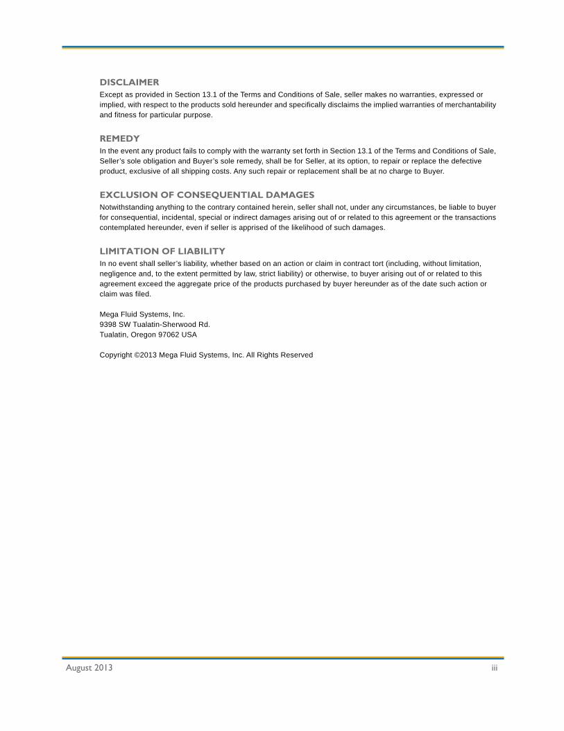
DI Water Startup and Leak Testing
The typical DI water startup and leak testing is performed before the chemical startup. This procedure requires the system to be powered up.
1. Provide clean DI water in source containers (totes/drums).
2. Ensure the system is On.
3. In manual mode, fill system with DI water.
4. Check the entire system for leaks. Fix any leaks that may occur.
5. Set and record all timers, runtime setpoints, and alarm setpoints.
6. Set the system recipe(s).
7. Calibrate the flowmeters. Record the K-factor for each flowmeter.
8. Calibrate the analytical devices. Record the settings.
9. Run the system in automatic mode, simulating a POU consumption.
10. Return the system to normal automatic operation and observe the system for a period that represents a complete cycle of functions.
System Testing
The typical system testing is performed before the chemical startup. This procedure requires the system to be powered up.
CAUTIONELECTRICAL HAZARD — TYPE 3!
Live circuits may be exposed and accidental contact is possible. Use extreme caution to avoid electrical shock.
CAUTIONELECTRICAL HAZARD — TYPE 3!
Live circuits may be exposed and accidental contact is possible. Use extreme caution to avoid electrical shock.

MegaPure 50, Model 303 Installation
August 2013 3-9
Alarm Test
1. Test all critical alarms. With the system running, trigger the alarms and ensure the system stops pumping chemical.
2. Test all process alarms. When the system is running, trigger the alarms and verify the portion of the system associated with the alarm stops. Some alarms may require a brief setup to simulate certain portions of a process.
3. Test all warnings. When the system is running, trigger the alarms and ensure the alarm sounds but does not shut down any part of the system.
Communications Test
1. Ensure no communication or other system alarms may interfere with the communi-cation test.
2. Initiate a chemical demand or other communication parameter and ensure the systems interact in accordance with the signal being sent. The system receiving the signal should respond by performing a function or returning a status signal to the host system.
3. Return systems to normal automatic operation and observe the communications for a period that represents a complete cycle of functions.
4. Perform this test for each component connected to the MegaPure 50, Model 303.
Chemical Startup and Testing
The typical chemical startup and testing is performed to complete the installation procedure. This procedure requires the system to be powered up.
1. Drain the DI water from the system. Purge the system with N2, as required.
CAUTIONELECTRICAL HAZARD — TYPE 3!
Live circuits may be exposed and accidental contact is possible. Use extreme caution to avoid electrical shock.
CAUTIONUSE PROPER PPE WHEN HANDLING CHEMICAL!
Potentially hazardous chemicals may be present in the system during the Chemical Startup and Testing. Wear proper PPE to
avoid injury.

3-10 August 2013
Installation MegaPure 50, Model 303
2. Connect the source chemical(s).
3. Run the system in automatic mode with chemical(s). Monitor the system closely for leaks.
4. Flush the chemical(s) to the drain. Continue flushing and particle count testing until system specifications are met.
5. Qualify the system through system readings or qualified laboratory analysis. Record all results, including blend ratio, volumes, and analytical specifications.
6. Perform a final system checkout and qualification.

MegaPure 50, Model 303 Installation
August 2013 3-11
Automatic and Solenoid Valves
The following is a complete list of automatic valves (AVs) and their associated solenoid valves (EVs) for the MegaPure 50, Model 303.
Table 3-1. MegaPure 50, Model 303 Automatic and Solenoid Valves
P&ID Location
AV Designation
EV Designation
Description Comments
Pg. 2 AV1 SV-1 Chemical Discharge Isolation Valve NCPg. 2 AV2 SV-2 Filter Degassing Isolation Valve NCPg. 2 AV3/AV5 SV-3 Pump Pneumatic Supply Selection
Valve / Drum Blanket Isolation ValveNC-NO / NC
Pg. 2 AV4A/B SV-4 Drum #1 Supply Isolation Valve / Drum #2 Supply Isolation Valve
NC / NO
Pg. 2 SPARE SV-5 SparePg. 2 SPARE SV-6 SparePg. 2 SPARE SV-7 SparePg. 2 SPARE SV-8 SparePg. 2 SPARE SV-9 SparePg. 2 SPARE SV-10 SparePg. 2 SPARE SV-11 SparePg. 2 SPARE SV-12 SparePg. 2 SPARE SV-13 SparePg. 2 SPARE SV-14 SparePg. 2 SPARE SV-15 SparePg. 2 SPARE SV-16 Spare

3-12 August 2013
Installation MegaPure 50, Model 303
Device Reference List
The following is a complete device reference list for the MegaPure 50, Model 303.
Table 3-2. Device Reference List
P&ID Location
Type Number State Description Comment
1/F6 AV 1 NC Valve, Diaphragm, Pneumatic,2-way, Chemical Discharge Isolation
1/C6 AV 2 NC Valve, Diaphragm, Pneumatic, 2-way, Filter Degassing Isolation
1/C10 AV 3 NC/NO Valve, Diaphragm, Pneumatic, 3-way, Pump Pneumatic Supply Selection
1/D15 AV 4A NC Valve, Diaphragm, Pneumatic, 2-way, Drum #1 Isolation
1/D14 AV 4B NO Valve, Diaphragm, Pneumatic, 2-way, Drum #2 Isolation
1/F12 AV 5 NC Valve, Diaphragm, Pneumatic, 2-way, Drum Blanket Isolation
2/G15 BV 1 Closed Valve, Ball, 2-way, N2 Supply Isolation2/G10 BV 2 Closed Valve, Ball, 2-way, CDA Supply Isolation2/H14 BV 7 Closed Valve, Ball, 2-way, Z-Purge Isolation1/D10 Dampener #1 ----- Dampener, Pulsation, Pump P11/A15 Drum #1 ----- Drum, Chemical Supply, Principle1/A14 Drum #2 ----- Drum, Chemical Supply, Redundant1/D7 FL 1 ----- Filter, Principle2/F13 FR 1 Field Set Flow Regulator, Manual, Pneumatic
Compartment Purge2/F12 FR 2 Field Set Flow Regulator, Manual, Drum Blanket2/H12 FR 7 Field Set Flow Regulator, Manual, Z-Purge1/A9 LD 1 NC Sensor, Leak, Process Cabinet
1/D13 LS 1 NO Sensor, Proximity, Drum Empty1/E6 LS 2 NO Sensor, Proximity, Filter Degassing Line
1/C15 MV 1A Closed Valve, Diaphragm, Manual, 2-way, Drum #1 Supply Isolation
1/C14 MV 1B Closed Valve, Diaphragm, Manual, 2-way, Drum #2 Supply Isolation
1/B12 MV 2 Closed Valve, Diaphragm, Manual, 2-way, Pump P1 Inlet Isolation
1/E10 MV 3 Closed Valve, Diaphragm, Manual, 2-way, Pump P1 Exit Isolation

MegaPure 50, Model 303 Installation
August 2013 3-13
1/B11 MV 4 Closed Valve, Diaphragm, Manual, 2-way, Pump P1 Drain Isolation
1/F7 MV 5 Closed Valve, Diaphragm, Manual, 2-way, Filter FL1 Vent Isolation
1/C7 MV 6 Closed Valve, Diaphragm, Manual, 2-way, Filter FL1 Drain Isolation
1/E9 MV 7 Closed Valve, Diaphragm, Manual, 2-way, Filter FL1 Inlet Isolation
1/G6 MV 9 Closed Valve, Diaphragm, Manual, 2-way, Chemical Supply Isolation
1/C11 P 1 ----- Pump, Chemical Dispense, Principle2/D14 PG 1 ----- Gauge, N2 Supply to Solenoids2/F14 PG 2 ----- Gauge, N2 Supply to Drum Blanket2/G9 PG 3 ----- Gauge, CDA Supply to Pump P11/E5 PG 4 ----- Gauge, Filter FL1 Exit Pressure Indicator1/E8 PG 5 ----- Gauge, Filter FL1 Inlet Pressure Indicator1/F10 PG 6 -1" H2O Gauge, Vacuum, Exhaust2/H13 PG 7 ----- Gauge, Pressure, Z-Purge2/C14 REG 1 70 PSIG Regulator, Pressure, N2 Supply to Solenoids2/F14 REG 2 1 PSIG Regulator, Pressure, N2 Supply to Drums2/G9 REG 3 60 PSIG Regulator, Pressure, CDA Supply to Pump P12/H13 REG 7 4" H2O Regulator, Pressure, CDA Supply to Z Purge
Line2/D13 RV 1 80 PSIG Relief Valve, N2 Supply to Solenoids
Overpressure2/F12 RV 2 2 PSIG Relief Valve, N2 Drum Blanket Overpressure2/G7 RV 3 70 PSIG Relief Valve, Pump P1 Pneumatic Supply
Overpressure2/H5 RV 7 3 PSIG Relief Valve, Z-Purge Line
Table 3-2. Device Reference List (continued)
P&ID Location
Type Number State Description Comment

3-14 August 2013
Installation MegaPure 50, Model 303

August 2013 4-1
Chapter 4: Sequence of Operation
This chapter contains the following information:
Sequence of Operations Overview................................................................4-2Pump and Start-Up of the Supply Drums ................................................4-2Dispense to the Process Tools ...............................................................4-3Station Shutdown ...................................................................................4-3

4-2 August 2013
Sequence of Operation MegaPure 50, Model 303
Sequence of Operations Overview
The MegaPure 50 Chemical Distribution System, Model 303 uses a drum and filtration circuit to supply chemical to multiple use points when a demand signal is received. When a supply drum is placed in service, the filter is primed, then chemical is “available” to be distributed to points of use on demand. When a drum is detected to be empty, the tool automatically switches over to the standby drum, and an alarm is activated so that the operator can have a new drum placed in service
The station remains in standby mode (pump off) until (1) it receives a signal demanding chemical or (2) when the station is in EMO condition. The system will be available to distribute chemical upon a demand signal after the drum has been put on line and the filter primed.
The Allen Bradley brick PLC MicroLogix™ 1000 controls the operating, sensing, and safety of the unit. It is located in a purged control compartment in the cabinet.
The following sections elaborate in detail the full sequence of operations.
Pump and Start-Up of the Supply Drums
The supply drums are connected to the MegaPure 50, Model 303 by means of two sets of supply quick connect couplers. The drums are placed on line by selecting A, B, or A/B from the front panel.
The on-line drum will be pumped to prime the filters and then the pump will turn off. A signal is sent to the use points that chemical is available. The signal indicates the on-line drum is available to pump chemical to the use points when a demand signal is received from the tool requiring chemical.
Upon receipt of a demand signal, the pump will turn on, the output valve will open, and chemical will be pumped through a single-pass filtration circuit to the system initiating the chemical demand.
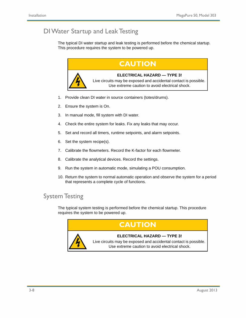
When the on-line drum is sensed to be empty, the station annunciator will alarm and the Drum Empty button will flash to notify the operator the drum is empty. The system will automatically switch the “Stand-By” drum to “On Line” status and continue pumping chemical until the demand is met. The operator will change out the empty drum.
If the on-line drum is sensed to be empty and the “Stand-By” drum is empty, the station annunciator will alarm and the Drum Empty button light will remain lit to notify the operator that both drums are empty. The system will shut down and send a message to the use points that chemical is not available. The operator will need to replace the empty drums and placed on line by selecting A, B, or A/B from the front panel.

MegaPure 50, Model 303 Sequence of Operation
August 2013 4-3
Dispense to the Process Tools
The MegaPure 50, Model 303 remains in stand-by mode with its pump off until a chemical demand signal is received. Once a demand signal is received, the pump will turn on and dispense chemical through the output filter to the distribution points until the demand signal is removed or an EMO occurs.
Station Shutdown
A chemical dispense station shutdown will be caused by the EMO or critical alarm as described in the Alarms and Warnings (page 6-1) chapter.
A critical alarm will cause the station's buzzer to sound, all valves to close, the pumps to turn off, and the appropriate remote alarms to actuate. The alarm condition must be addressed, and the Silence button and Reset button pressed to continue operation.
EMO activation will remove all power from the tool. The EMO push button will have to be pulled out to restore power to the tool. All starts and restarts will require the station to execute the complete start-up sequence.

4-4 August 2013
Sequence of Operation MegaPure 50, Model 303

MegaPure 50, Model 303 Sequence of Operation
August 2013 4-5

4-6 August 2013
Sequence of Operation MegaPure 50, Model 303

MegaPure 50, Model 303 Sequence of Operation
August 2013 4-7

4-8 August 2013
Sequence of Operation MegaPure 50, Model 303

August 2013 5-1
Chapter 5: System Operation
This chapter contains the following information:
Operating Procedures...................................................................................5-2Starting the System ................................................................................5-2Shutting the System Down......................................................................5-3Initial Chemical Start-up (Automatic Operation) ......................................5-3Drum Start-up Operation.........................................................................5-3Manual Start-up Operation......................................................................5-4System Shutdown and Restart................................................................5-4Restarting After an EMO Shutdown or Unexpected Loss of Power .........5-5Responding to Alarms ............................................................................5-5
Leak Condition Alarm .......................................................................5-5Drum Empty Alarm ...........................................................................5-6
PLC Micrologix™ 1000 Overview..................................................................5-7PLC Micrologix 1000 Button Descriptions ...............................................5-7

5-2 August 2013
System Operation MegaPure 50, Model 303
Operating Procedures
The instructions in this section are primarily for operators monitoring the MegaPure 50, Model 303. The procedures for responding to alarms and troubleshooting are included in this section.
Starting the System
Start the system by performing the following steps.
1. Toggle the AC disconnect switch to the On position.
2. Ensure that the EMO button is disengaged (pulled out).
3. Place the Drum switch in the A/B position.
4. Place the Man/Auto switch in the Auto position.
5. Turn the key switch from the Off position to the On position.
6. Press the Start button.
If the system fails to start, check the following items:
• AC disconnect is in the On position.
• EMO button is disengaged (pulled out).
• All doors and electrical cabinet are closed.
• Power is supplied to the system (the green Start button has been pressed).
Note: A restart is required after a power outage. Refer to the Restarting After an EMO Shutdown or Unexpected Loss of Power (page 5-5) section before restarting the system.

MegaPure 50, Model 303 System Operation
August 2013 5-3
Shutting the System Down
Perform the following steps to shut down the system.
1. Press the EMO button.
2. Toggle the AC Disconnect switch to the Off position.
Initial Chemical Start-up (Automatic Operation)
Once facility connections have been established, the system is prepared for initial chemical start-up. This section describes the procedures for placing the MegaPure 50, Model 303 in Automatic mode.
1. Close the electrical cabinet and the chemical compartment doors prior to start-up.
2. Ensure the main electrical disconnect is in the On position and the key is in the On/Off key switch.
3. Place the keyswitch in the On position.
4. Continue with the Drum Start-up Operation (page 5-3).
Drum Start-up Operation
Perform the following steps to start drum operation.
1. Place the Drum switch to A, B, or A/B.
2. Press the Start Drum button.
The system will start by priming the filters. An available signal is sent to the Point-of-Use (POU) systems once the filters are primed.
When a demand signal is received, the pump will turn on, the output valve will open, and chemical will be pumped through a single pass filtration circuit to the tool initiating the chemical demand.
NOTICEFLUSH AND PURGE MAY BE REQUIRED!
If the system is shut down for an extended period of time, complete a full flush and purge.

5-4 August 2013
System Operation MegaPure 50, Model 303
Manual Start-up Operation
Perform the following steps to start the system in Manual mode.
1. Toggle the AC disconnect switch to the On position.
2. Verify that the EMO button is disengaged (pulled out).
3. Place the Man/Auto switch in the Man position.
4. Turn the key switch from the Off position to the On position.
System Shutdown and Restart
Several conditions or activities may lead to system shutdown. For “normal” or planned system shutdown, perform the following procedure.
1. Turn the key switch to the Off position.
2. Toggle the AC disconnect switch to the Off position.
The following lists the common situations leading to system shutdown and the steps for restarting.
Cause of Shutdown System RestartEMO Activation Reposition the EMO in the normal position and follow initial start-
up procedures, either conducting the initial filtration or selecting the bypass option.
Main Electrical Disconnect OFF Place the switch in the On position and follow the initial start-up procedures, either conducting the initial filtration or selecting the bypass option.
Facility Power Interruption Verify all switches are in the On position and follow the initial start-up procedures, either conducting the initial filtration or selecting the bypass option.
Any Door Interlocks Activated Disengage the activated interlock (close any open doors) and follow the initial start-up procedures, either conducting the initial filtration or selecting the bypass option.
Hood Interlock Activated Disengage the activated interlock and follow the initial start-up procedures, either conducting the initial filtration or selecting the bypass option.
Specific Critical Alarm Activation Determine the cause of the alarm and correct it. Follow the initial start-up procedures, either conducting the initial filtration or selecting the bypass option

MegaPure 50, Model 303 System Operation
August 2013 5-5
Restarting After an EMO Shutdown or Unexpected Loss of Power
If the system shuts down while performing an operation, it will not continue where it left off after the restart. Perform the following procedure when restarting the system after an unexpected shutdown.
• If the system shut down due to the EMO switch, pull the EMO button out.
• If the system shut down due to the door interlocks, verify all doors are closed.
• If the system shut down due to the exhaust interlock:
a. Check the exhaust system for proper operation.
b. Check the exhaust high and low pressure setpoints.
c. Restart the system by following the procedure outlined in Starting the System (page 5-2).
• If the system has been inactive with chemical in the lines for an extended period of time, it may be desirable to manually flush the filters.
a. Place the system in Automatic mode by following the procedure outlined in Initial Chemical Start-up (Automatic Operation) (page 5-3).
Responding to Alarms
Alarms are activated when one or both of the supply drums are empty or if a leak condition is present. The audible annunciator will sound and the Drum Empty button will flash on and off if one drum is empty and remain solid if both drums are empty.
Leak Condition Alarm
A leak condition exists if the audible annunciator sounds but the Drum Empty button remains unlit.
Responding to a Leak Alarm:
1. Press the Silence button to silence the audible annunciator.
2. Locate and repair the leak condition.
3. Press the Reset button to reset the leak alarm.

5-6 August 2013
System Operation MegaPure 50, Model 303
Drum Empty Alarm
Responding to a Drum Empty Alarm:
1. Press the Silence button to silence the audible annunciator.
2. Replace the supply drum(s).
3. Press the Drum Empty button.
4. Press the Reset button to reset the drum alarm. If the problem still exists the alarm will be reactivated.

MegaPure 50, Model 303 System Operation
August 2013 5-7
PLC MicroLogix™ 1000 Overview
The MegaPure 50, Model 303 includes an PLC MicroLogix 1000 Operator Interface control system. This interface enables the operator to control all system operations through the use of panel buttons. For example, pressing the Start Drum button will start a purge and then place the drum(s) online.
Detailed information about the PLC MicroLogix 1000 interface is provided below.
PLC MicroLogix 1000 Button Descriptions
All PLC MicroLogix 1000 interface button functions are described in the following table.
Table 5-1. PLC MicroLogix 1000 Button Descriptions
Button DescriptionUse the Drum Switch to set the drum configuration. Setting to A/B will allow the MegaPure 50, Model 303 to automatically switch between Drum A and B. Setting to A or B will only allow the MegaPure 50, Model 303 to use the A or B drum.
Use the Auto/Manual Switch to toggle the system between automatic and manual modes of operation. The MegaPure 50, Model 303 should remain in automatic mode when in normal operation.
Press the Start Drum button to initiate a purge and place the first drum online.
Use the Chem Dispense light to determine when the MegaPure 50 Chemical Distribution System, Model 303 is dispensing chemical. The light will remain solid when there is a chemical demand from the POUs, a drum is online, and no alarm conditions are present.
5-8 August 2013
System Operation MegaPure 50, Model 303
Use the Drum Empty button to determine when a drum is empty. The Drum Empty light will blink when one drum is empty and will remain solid when both drums are empty.
Press the Silence button to silence the audible annunciator. The alarm condition must be remedied or the audible annunciator will reactivate.
Press the Reset button to reset active alarm conditions. The alarm condition(s) must be remedied before the system is reset.
Table 5-1. PLC MicroLogix 1000 Button Descriptions (continued)
Button Description

August 2013 6-1
Chapter 6: Alarms and Warnings
This chapter contains the following information:
Software Interlocks .......................................................................................7-2Critical Interlocks ....................................................................................7-2Warnings ................................................................................................7-2Interlock Alarms......................................................................................7-3

6-2 August 2013
Alarms and Warnings MegaPure 50, Model 303
Software Interlocks
A software interlock is a computer-controlled lock/alarm under which a device may or may not be allowed to operate. Software interlocks are incorporated in order to ensure the safety of the operator and to protect the product being processed.
An active alarm indicates the interlock is currently tripped, but has not been acknowledged. The audible annunciator, is sounded when active alarms exist. When an operator presses the acknowledge key, the audible annunciator is turned off, and the alarm is lowered to the acknowledged state. When the operator presses the reset key, the alarm is reset. If the condition which caused the interlock has not been corrected, the alarm is reactivated. The MegaPure 50 Chemical Distribution System, Model 303 has two types of alarms: critical interlocks and warnings.
Critical Interlocks
Critical interlocks are activated by situations that require immediate attention and threaten the performance of the system. Critical interlocks cause a shutdown of the system and pose a potentially dangerous situation to the operator and system if not addressed promptly.
Warnings
Warnings are activated by those situations that do not need immediate attention, but could escalate into a more serious problem if ignored.

MegaPure 50, Model 303 Alarms and Warnings
August 2013 6-3
Interlock Alarms
The following table lists all interlocks, provides a list of possible causes, and suggests actions to be taken in order to correct the condition which has caused the interlock.
Table 6-1. Interlocks List
Interlock Tag Possible Cause Required Action
Audible Annunciator Activated
Leak in compartment. 1. Check cabinet for source of leak.
2. Repair leak.
3. Clean and dry cabinet.Leak detector faulty. Verify leak detector operation and
replace, if necessary.Low voltage to leak detector. Check voltage (24 VDC).
Drum Empty Light on and Audible Annunciator
Activated
Both slurry drums/totes empty. 1. Replace slurry drums/totes.
2. Verify one drum alarm was activated.
Drums not online. Verify drums are online if full.Air in the slurry. 1. Check plumbing for loose fittings
or bad seals.
2. Check drum connections for proper fit.
3. Verify dip tubes correctly placed.Level sensor incorrectly placed. Check placement.Level sensor incorrectly set. Calibrate level sensor.Level sensor faulty. Replace level sensor.Low voltage to level sensor. Check voltage (24 DC).Wiring to the SLC terminal blocks faulty.
Verify I/O signals.

6-4 August 2013
Alarms and Warnings MegaPure 50, Model 303
Drum Empty Light Blinking and Audible
Annunciator Activated
One slurry drums/tote is empty. Replace slurry drum/tote.Drum not online. Verify drum are online if full.Air in the slurry. 1. Check plumbing for loose fittings
or bad seals.
2. Check drum connection for proper fit.
3. Verify dip tubes correctly placed.Level sensor incorrectly placed. Check placement.Level sensor incorrectly set. Calibrate level sensor.Level sensor faulty. Replace level sensor.Low voltage to level sensor. Check voltage (24 DC).Wiring to the SLC terminal blocks faulty.
Verify I/O signals.
Table 6-1. Interlocks List (continued)
Interlock Tag Possible Cause Required Action
August 2013 7-1
Chapter 7: Maintenance
The procedures in this chapter are used during general preventative maintenance procedures but also apply when troubleshooting component problems. Read and follow the Safety Precautions (page 7-3) section before attempting any preventative maintenance or troubleshooting procedures.
Safety Precautions........................................................................................8-3General System Maintenance .......................................................................8-4
Removing and Isolating Components .....................................................8-4Removing and Isolating Electrical Components ......................................8-5Compact Flash Card ...............................................................................8-7Pressure Reducing Regulators ...............................................................8-7
Preventive Maintenance ...............................................................................8-8Maintenance Schedule ...........................................................................8-8
Preparation.......................................................................................8-8Equipment ........................................................................................8-8
Weekly Preventive Maintenance Procedures ................................................8-9Visual System Inspection........................................................................8-9Verifying the Device Settings ................................................................8-10
Monthly Preventive Maintenance Procedures .............................................8-12Checking Pump Operation ....................................................................8-12Checking Leak Detectors......................................................................8-12
Quarterly Preventive Maintenance Procedures ...........................................8-15Testing Alarms......................................................................................8-15Valves and Pressure Gauges ...............................................................8-16
Electrical Solenoid Valves (EV) ......................................................8-16Automatic Valves (AV)....................................................................8-17Check Valves (CV) .........................................................................8-17Manual Valve (MV) .........................................................................8-18Pressure Relief Valve .....................................................................8-18Gas Line Maintenance....................................................................8-19
Semi-Annual Preventive Maintenance Procedures .....................................8-22Fittings..................................................................................................8-22
Checking the Fittings ......................................................................8-22Replacing Fittings ...........................................................................8-23
Rebuilding Pumps.................................................................................8-24Isolating and Removing Pumps ......................................................8-24

7-2 August 2013
Maintenance MegaPure 50, Model 303
Annual Preventive Maintenance Procedures...............................................8-26Lithium Battery......................................................................................8-26
Replacing the Lithium Battery .........................................................8-26Disposing the Lithium Battery .........................................................8-27
Replacing the Filters .............................................................................8-28Pulsation Dampener .............................................................................8-30EMO Testing.........................................................................................8-31
Completing Preventive Maintenance Procedures........................................8-32Cabinet Cleaning ..................................................................................8-32
Maintenance Forms ....................................................................................8-33Work Order Form..................................................................................8-34Preventive Maintenance Form ..............................................................8-35Device Settings Record Sheet ..............................................................8-37

MegaPure 50, Model 303 Maintenance
August 2013 7-3
Safety Precautions
Review all of the following safety messages before performing any maintenance procedures. Compliance to safety warnings prevent unnecessary risks to operators and equipment.
WARNINGCHEMICAL HAZARD!
The exhaust effluent may contain chemical (vapor or liquid). It should be handled and treated accordingly for compliance to
safety and pollution control regulations. Supplemental exhaust may be required for maintenance tasks.
ELECTRICAL HAZARD — TYPE 3!Risk of exposure to hazardous electrical current. Use extreme
caution while performing preventive maintenance procedures in order to avoid accidental contact with energized parts.
NOTICEUSE PROPER LIGHTING!
Use portable lighting (lighting level of minimum 30 foot-candles) when completing service.
WARNINGCHEMICAL HAZARD!
Wear acid-resistant gloves, chemical safety goggles and full-face shield, and protective clothing such as a lab coat, apron, or
coveralls as recommended in the MSDS during preventive maintenance procedures. Refer to the site MSDS for chemical-
specific information.
CAUTIONLOUD NOISE HAZARD!
Use hearing protection when pumps are on and any pump access panel is open.

7-4 August 2013
Maintenance MegaPure 50, Model 303
General System Maintenance
All routine maintenance is performed from the front of the system. The rear system panels are not intended to be removed for maintenance.
Removing and Isolating Components
Use this procedure as a guideline for removing a component from the system for maintenance or replacement.
• Read all safety notices before beginning any procedures.
• Always wear acid-resistant gloves, chemical safety goggles and full-face shield, and protective clothing such as a lab coat, apron, or coveralls as recommended in the MSDS.
• Use lockout/tagout devices, as required.
• Isolate and relieve potential energy before opening lines or attempting electrical maintenance.
• Follow site specific requirements and procedures.
1. Wear acid-resistant gloves, chemical safety goggles and full-face shield, and protective clothing such as a lab coat, apron, or coveralls as recommended in the MSDS. Refer to the MSDS and site regulations.
Equipment Required • MSDS for all system chemistry.• Acid-resistant gloves, chemical safety goggles and full-face
shield, and protective clothing such as a lab coat, apron, or coveralls as recommended in the MSDS.
• Chemical absorbent pads and wipes, and other safety equipment as recommended on the MSDS.
• Appropriate chemical waste container as recommended on MSDS.
• Auxiliary lighting.• Appropriate tool set.• Replacement components.
NOTICESSHUT DOWN POWER FOR ELECTRICAL MAINTENANCE!Always shut off power before performing electrical procedures.

MegaPure 50, Model 303 Maintenance
August 2013 7-5
2. Place the system into manual operating mode.
3. Preferably, shut down power to the system. It may be necessary to shut down electrical power after relieving pressure in the lines if automatic valves must be toggled.
4. Lockout/tagout the A/C disconnect switch.
5. Close the component isolation valves.
6. Toggle or open valves to release pressure in the line.
7. Lock out the isolation valves.
8. Remove the component.
9. Repair or replace the component.
10. Use a hand sprayer to clean or remove any chemical in the cabinet interior.
11. Remove lockout/tagout devices and open isolation valves.
12. Restore system power.
13. Perform necessary tests in Manual mode to ensure procedure was executed correctly.
14. Return system to Auto mode.
Removing and Isolating Electrical Components
Use this procedure as a guideline for removing and isolating electrical components.
• Read all safety notices before beginning any procedures.
• Always wear protective gear as recommended on the MSDS.
• Use lockout/tagout devices, as required.
• Isolate and relieve potential energy before opening lines or attempting electrical maintenance.
• Follow site specific requirements and procedures.
CAUTIONPRESSURE HAZARD!
Relieve pressure in lines before loosening fittings.

7-6 August 2013
Maintenance MegaPure 50, Model 303
1. Wear acid-resistant gloves, chemical safety goggles and full-face shield, and protective clothing such as a lab coat, apron, or coveralls as recommended in the MSDS.
2. Lockout/tagout the A/C disconnect switch.
3. Complete the replacement.
4. Remove lockout/tagout device.
5. Start up the system.
Equipment Required • MSDS for all system chemistry.• Acid-resistant gloves, chemical safety goggles and full-face
shield, and protective clothing such as a lab coat, apron, or coveralls as recommended in the MSDS.
• Chemical absorbent pads and wipes, and other safety equipment as recommended on the MSDS.
• Appropriate chemical waste container as recommended on MSDS.
• Auxiliary lighting.• Appropriate tool set.• Replacement components.
CAUTIONELECTRICAL HAZARD — TYPE 3!
Disconnect power and lockout/tagout to remove electrical hazard before performing any electrical procedures.
NOTICEOBTAIN APPROPRIATE APPROVAL!
Electrical procedures require the system to be shut down. Obtain appropriate approval and notify affected personnel before proceeding.

MegaPure 50, Model 303 Maintenance
August 2013 7-7
Compact Flash Card
The PLC is supplied with an Allen-Bradley Industrial Compact Flash card. The Compact Flash contains a copy of the current program. In the event of corrupt memory, the system program automatically loads from the Compact Flash and resumes operation.
Program changes are not automatically sent and uploaded to the Compact Flash card. A Controls Engineer must download any changes to the Compact Flash. The downloading must occur when then PLC is in the program mode.
Pressure Reducing Regulators
Reducing regulators control the incoming pressure to an exact pressure no matter what happens to the incoming pressure. The regulator design is based on a diaphragm and needle through a hole principle. As the regulator knob is adjusted, the tapered needle going through the hole gets larger. The diaphragm moves to compensate for any changes in incoming CDA/N2 pressure. The attached gauge has an accuracy of +/-5%. The flow is manually adjusted.
Figure 7-1. Regulator Example
Indications of a premature regulator failure are an inability to maintain a stable pressure value, fluctuating pressure value, the regulator creeps (up or down), or the gauge needle sticks, and then jumps up or down. When a regulator fails it remains in the open position, or may stop regulating and then open. If an external leak is developed, the downstream pressure is bled off to the atmosphere.
Note: Program mode shuts down the entire system.

7-8 August 2013
Maintenance MegaPure 50, Model 303
Preventive Maintenance
Effective Preventive Maintenance (PM) maintains the system in optimal working order and ensures that the warranty extends to the equipment. This section provides a recommended PM schedule and includes weekly, monthly, quarterly, semiannual, and annual PM procedures. Retain copies of the completed preventive maintenance schedule to provide a history of the maintenance performed.
Maintenance Schedule
Prior scheduling of Preventive maintenance activities helps prevent unexpected downtime and disrupting the distribution system. Follow site specific procedures for notifying affected personnel before performing preventive maintenance. Typical site requirements include:
• obtaining a work order
• notifying the appropriate personnel, and
• applicable safety monitoring stations.
Preparation
Prior to starting preventive maintenance, review all appropriate procedures. Ensure all equipment is available, work permits are approved, and all affected personnel have been notified. Before replacing any components, ensure the components are on hand. Review all site requirements and procedures, including spill procedures, buddy systems, and PPE. Wear acid-resistant gloves, chemical safety goggles and full-face shield, and protective clothing such as a lab coat, apron, or coveralls as recommended in the MSDS. Review site MSDS for each chemical used in the system.
Equipment
Gather all required equipment before performing maintenance procedures. The recommended equipment is listed each preventive maintenance section in this chapter.

MegaPure 50, Model 303 Maintenance
August 2013 7-9
Weekly Preventive Maintenance Procedures
Perform the following preventive maintenance procedures as part of the weekly maintenance schedule (Table 7-2, on page 35).
Visual System Inspection
A thorough visual inspection verifies the system is operating correctly and alerts the operator to potential maintenance required. Maintenance issues identified during the visual inspection should be reported and either corrected, or scheduled, at the earliest possible maintenance. Complete an informal inspection daily.
A complete visual inspection requires opening the s; follow all chemical and electrical hazard precautions. Follow all site-specific policies during the procedure.
Use the following list as a guideline for a visual inspection, however, this list may not be all-inclusive.
1. Wear acid-resistant gloves, chemical safety goggles and full-face shield, and protective clothing such as a lab coat, apron, or coveralls as recommended in the MSDS.
2. General system area.
a. Check area for leaks or spills. Correct according to site procedures.
b. Check area for hazardous conditions. Correct according to site procedures.
3. System exterior.
a. Ensure doors and electrical cabinet are closed.
b. Ensure system is on.
c. Check double containment lines for evidence of leaks. Repair leaks, as necessary.
Equipment Required • MSDS for all system chemistry.• Acid-resistant gloves, chemical safety goggles and full-face
shield, and protective clothing such as a lab coat, apron, or coveralls as recommended in the MSDS.
• Chemical absorbent pads and wipes, and other safety equipment as recommended on the MSDS.
• Appropriate chemical waste container as recommended on MSDS.
• Auxiliary lighting.

7-10 August 2013
Maintenance MegaPure 50, Model 303
d. Ensure system exhaust is operating within the exhaust setpoints. Exhaust setpoints are field set and are located on the exhaust pressure switch in the corner of the gas compartment.
4. System operation.
a. Ensure system is in normal operating mode (automatic or manual).
b. Check alarm status. Acknowledge all alarms.
c. Review alarm and maintenance log.
5. Chemical section of system.
a. Check cabinet floor and system piping for leaks and spills. Correct according to site procedures.
b. Check chemical inlets and outlets on cabinet and drums for leaks or loose fittings. Correct according to site procedures.
c. Check system components for corrosion or chemical residue. Correct according to site procedures.
6. Electrical section of system.
a. Check system power.
b. Ensure data highway connections are solidly connected.
c. Check wiring compartment for corrosion, burns, or irregular odor. Correct according to site procedures.
d. Check for loose wire connections. Correct according to site procedures.
Verifying the Device Settings
Obtain the latest device settings list for the system (Device Reference List (page 3-12)). Investigate deviations in the device settings before resetting values.
Inspecting the device settings requires opening the s and taking the proper precautions to avoid chemical and electrical hazards.
Equipment Required • MSDS for all system chemistry.• Acid-resistant gloves, chemical safety goggles and full-face
shield, and protective clothing such as a lab coat, apron, or coveralls as recommended in the MSDS.
• Auxiliary lighting.• Device Settings Record Sheet• Flow Schematics or P&ID

MegaPure 50, Model 303 Maintenance
August 2013 7-11
1. Wear acid-resistant gloves, chemical safety goggles and full-face shield, and protective clothing such as a lab coat, apron, or coveralls as recommended in the MSDS.
2. Locate each device on the Device Settings List, and compare the actual setting with the recorded setting. Use the P&ID to aid in locating each device. P&ID Schematic (page 8-5)
3. Record all deviations from the previously recorded settings on the Device Settings Record Sheet (page 7-37).
4. Consult with the Process Engineer to verify that deviations require correction.
5. Correct deviations, as required.

7-12 August 2013
Maintenance MegaPure 50, Model 303
Monthly Preventive Maintenance Procedures
Perform the following preventive maintenance procedures as part of the monthly maintenance schedule (Table 7-2, on page 35).
Checking Pump Operation
Pumps can malfunction due to poor maintenance (i.e., missing preventive maintenance based on runtime). Lack of maintenance can cause internal parts to fail. Other reasons for failure include running dry for long periods of time, dead heading, ingesting foreign objects, dried slurry particles, poor rebuilding techniques, or bad CDA/N2.
Figure 7-2. Bellows Pump
Checking the pump operation requires opening the system and taking proper precautions to avoid chemical and electrical hazards. Ensure the pump operates correctly by running the system. Should the pump need repair or replacement, refer to Isolating and Removing Pumps (page 7-24) for pump maintenance procedures.
Checking Leak Detectors
Leak detectors are a 24 VDC, Teflon-coated, paperless sensor. They are wired in a fail-safe configuration. The leak detector should be correctly placed in the mounting bracket. Malfunction can occur due to bad wiring or it can stick. On the puck-style leak detector, a leak is indicated if the red LED is displayed. The bit LED goes out if there is a leak because the voltage drops, therefore, a spark is not created if the system chemical is flammable.

MegaPure 50, Model 303 Maintenance
August 2013 7-13
Figure 7-3. Type of Leak Detector
Checking leak detectors requires taking the proper precautions to avoid chemical and electrical hazards.
1. Wear acid-resistant gloves, chemical safety goggles and full-face shield, and protective clothing such as a lab coat, apron, or coveralls as recommended in the MSDS.
Equipment Required • MSDSs for all system chemistry.• Acid-resistant gloves, chemical safety goggles and full-face
shield, and protective clothing such as a lab coat, apron, or coveralls as recommended in the MSDS.
• Chemical absorbent pads and wipes, and other safety equipment as recommended on the MSDS.
• Appropriate chemical waste container as recommended on MSDS.
• Auxiliary lighting.• Electrical schematics.
WARNINGCHEMICAL HAZARD!
Leak detectors are placed at the most likely spot to sense leaks. Chemical may be present. Wear acid-resistant gloves, chemical safety goggles and full-face shield, and protective clothing such
as a lab coat, apron, or coveralls as recommended in the MSDS. Refer to the site MSDS for chemical-specific
information.
Puck-style leak detector
Float-style leak detector

7-14 August 2013
Maintenance MegaPure 50, Model 303
2. The leak detector LED should be green, indicating no leak. The corresponding input LED on the PLC should also be lit.
3. Spray a small amount of water on the leak detector with the hand sprayer. The LED should change to red, indicating a leak. The corresponding input LED on the PLC should turn off.
• If the sensor does not change, test the wiring with another leak detector.
• If the replacement sensor functions, the first sensor was faulty.
• If the replacement sensor does not function, check leak detector wiring.
4. Replace the leak detector or repair the wiring, if required.
WARNINGCHEMICAL HAZARD!
The exhaust effluent may contain chemical (vapor or liquid). Handle and treat to comply with safety and pollution control
regulations. Supplemental exhaust may be required for maintenance tasks.

MegaPure 50, Model 303 Maintenance
August 2013 7-15
Quarterly Preventive Maintenance Procedures
Perform the following preventive maintenance procedures as part of the quarterly maintenance schedule (Table 7-2, on page 35).
Testing Alarms
Alarms in the system indicate critical errors, process problems and information. The proper functioning of all critical alarms helps ensure the safe operation of the system.
Testing the alarms requires opening the s and taking proper safety precautions to avoid chemical and electrical hazards. See the Alarms and Warnings (page 6-1) chapter for a listing of all alarms. Trigger alarms using the actions described in the Possible Reason column.
.
NOTICENOTIFY ALL APPROPRIATE PERSONNEL AND OBTAIN APPROVAL
BEFORE TESTING ALARMS!Triggering critical alarms may alert fab security and safety personnel, and
possibly cause an evacuation. Notify affected personnel and obtain all required approval before testing alarms.
WARNINGCHEMICAL HAZARD!
The exhaust effluent may contain chemical (vapor or liquid). Handle and treat to meet compliance with safety and pollution control regulations. Supplemental exhaust may be required for
maintenance tasks.

7-16 August 2013
Maintenance MegaPure 50, Model 303
Valves and Pressure Gauges
Numerous types of valves are used to control the flow of chemical, DI water, slurry, CDA/N2 throughout the system. The valves include:
• automatic
• manual
• diverter
• check
• needle
• ball
• relief
• pressure relief valve
• flow indicator control valve, and
• electric solenoid.
Automatic valves control process flow. Solenoid valves control the flow of CDA/N2 to the automatic valves. Manual valves, ball valves, and needle valves are used for isolation and shutoff. Diverter valves are used for samples and slipstreams. Check valves protect supply lines from contamination. Relief valves protect gas lines from over-pressurization.
Electrical Solenoid Valves (EV)
The electrical solenoid valves are not activated when the computer bit LED is Off and the associated valve LED is Off. Both LEDs are illuminated with the computer commands the EV and AV to activate. EVs include a button for manual activation.
Figure 7-4. Electrical Solenoid Valves Example
Top label corresponds to top valve.
Bottom label corresponds to bottom valve.

MegaPure 50, Model 303 Maintenance
August 2013 7-17
Malfunction occurs due to air leaking around the seals, chattering, weak local LED brightness, liquid from the exhaust, or the EV activates but does not fully shut off the associated AV. Refer to the Electrical Schematic (page 8-7) to match EV to AV devices.
Automatic Valves (AV)
Automatic valves operate by sending a 24 volt signal to the selected EV. The EV solenoid opens and the CDA/N2 flows to the selected AV. The AV valves are controlled by incoming CDA/N2 pressure, regulators, relieve valves, EVs, and air lines. Malfunction occurs if there are air line leaks, air line connector leaks, the air pressure is too low to hold the AV open, internal diaphragm leaks occur, or the return spring has lost its tension.
Figure 7-5. Automatic Valves Example
To troubleshoot the electrical or pneumatic command, put the AV in computer Manual mode to confirm correct output card and EV operation, and then check the air line for leaks with the local pressure gauge online, or move the air line to a different valve to confirm the valve is operating correctly when other factors are running normally.
Check Valves (CV)
Liquid check valves operate with a disk or ball system and are used to ensure that fluid is flowing in the correct direction.
Figure 7-6. Check Valve Example
Check valves are placed where back streaming could cause cross contamination of chemicals, slurry, CDA/N2, or water. The directional arrow is stamped in ink on the label so carefully observe the direction to prevent installing a valve backwards.
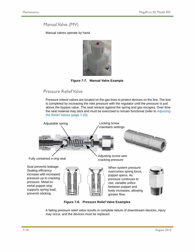
7-18 August 2013
Maintenance MegaPure 50, Model 303
Manual Valve (MV)
Manual valves operate by hand.
Figure 7-7. Manual Valve Example
Pressure Relief Valve
Pressure relieve valves are located on the gas lines to protect devices on the line. The test is completed by increasing the inlet pressure with the regulator until the pressure is just above the bypass value. The seat retracts against the spring and gas escapes. Over time the seat material may stick and must be exercised to remain functional (refer to Adjusting the Relief Valves (page 7-20).
Figure 7-8. Pressure Relief Valve Examples
A failing pressure relief valve results in complete failure of downstream devices, injury may occur, and the devices must be replaced.
Locking screw maintains settings
Adjustable spring
Fully contained o-ring sealAdjusting screw sets cracking pressure
When system pressure overcomes spring force, poppet opens. As pressure continues to rise, variable orifice between poppet and body increases, allowing greater flow.
Seal prevents leakage. Sealing efficiency increase with increased pressure up to cracking pressure. Metal-to-metal poppet stop supports spring load, prevents sticking.

MegaPure 50, Model 303 Maintenance
August 2013 7-19
Gas Line Maintenance
All components on each gas line should be checked for proper operation to prevent high gas pressure hazards and low pressure operation failures. Gas line maintenance includes checking the operation of the regulators, pressure switches, relief valves, and flow regulators.
Checking the gas line components requires opening the gas cabinet doors. All other doors must remain closed. Checking the gas line components may expose the operator to pressure hazards. Placing the system in Manual mode disrupts distribution.
Checking the Gas Line Components
1. Wear acid-resistant gloves, chemical safety goggles and full-face shield, and protective clothing such as a lab coat, apron, or coveralls as recommended in the MSDS.
2. Open the gas cabinet door. Ensure all other cabinet doors remain closed. Open doors may expose the operator to potential hazards.
3. If the line is equipped with a low-pressure switch, check the low-pressure switch before checking the high pressure switch or other components:
a. Decrease the regulator pressure until it is less than the low-pressure switch setting.
b. It may be necessary to vent the line to reach the low-pressure switch setting. Vent the line by operating a valve in Manual mode, running a pump, or opening a vent line valve to drain.
c. Ensure the low pressure alarm is activated at the correct line pressure. The alarm may be equipped with up to a 10 second delay. Provide adequate time for the alarm to activate.
Equipment Required • MSDS for all system chemistry.• Acid-resistant gloves, chemical safety goggles and full-face
shield, and protective clothing such as a lab coat, apron, or coveralls as recommended in the MSDS.
• Auxiliary lighting.• Device Reference List (page 3-12)• 4 mm Allen wrench.
DANGERPRESSURE HAZARD!
Open the door to the gas compartment only. Leave all other cabinet doors closed to protect from potential hazards.

7-20 August 2013
Maintenance MegaPure 50, Model 303
d. If the alarm is not activated at the correct pressure, adjust or replace the pressure switch.
4. If the line is equipped with a high-pressure switch:
a. Increase the regulator pressure until it is greater than the high-pressure switch setting.
b. Ensure the high-pressure alarm is activated at the correct line pressure. The alarm may be equipped with up to a ten second delay. Provide adequate time for the alarm to activate.
c. If the alarm is not activated at the correct pressure, adjust or replace the pressure switch.
Adjusting the Relief Valves
The relief valve is a device used in the CDA/N2 compartment to prevent high pressure buildup in the air lines. The relief valve will crack and relieve the air line when pressure exceeds the setpoint for the device. Also see Valves and Pressure Gauges (page 7-16).
1. Wear acid-resistant gloves, chemical safety goggles and full-face shield, and protective clothing such as a lab coat, apron, or coveralls as recommended in the MSDS.
2. Open the gas cabinet door. Ensure all other cabinet doors remain closed. Open doors may expose the operator to potential hazards.
3. Remove the allen lock nut with a 4 mm allen wrench.
4. Set the regulator pressure 1–2 psi below the relief valve setpoint.
DANGERPRESSURE HAZARD!
Open the door to the gas compartment only. Leave all other cabinet doors closed to protect the operator from potential
hazards.Release line pressure before replacing components.
NOTICEDO NOT COMPLETELY REMOVE ADJUSTMENT NUT!
Avoid removing the adjustment nut from valve body as it is difficult to replace.

MegaPure 50, Model 303 Maintenance
August 2013 7-21
5. Tighten the adjustment nut to increase pressure; loosen the adjustment nut to decrease pressure. Do not remove the adjustment nut from the valve body, it is difficult to replace. The nut is correctly adjusted when the relief valve begins leaking air 1–2 psi below the relief valve setpoint. Remove the allen wrench from the adjustment nut to verify the flow of gas.
6. Install the locking allen nut.
7. Set the pressure regulator to the desired relief pressure.
8. Test with the CDA/N2 pressure at the desired setting.
9. Repeat the procedure until the desired setting is achieved.
10. Increase the regulator pressure until it is 1–2 psi below the relief valve setting. The relief valve should begin to release gas.
11. Increase the regulator pressure until it is at the relief valve setting. The relief valve should be at full release. It the relief valve is activated at the correct pressure, adjust or replace the relief valve.
12. Return all components to their original device settings on the device list.
13. Repair or replace pressure switches, as required.
14. Repair or replace relief valves, as required (refer to Adjusting the Relief Valves (page 7-20).

7-22 August 2013
Maintenance MegaPure 50, Model 303
Semi-Annual Preventive Maintenance Procedures
Perform the following preventive maintenance procedures as part of the semi-annual maintenance schedule (Table 7-2, on page 35).
Fittings
Flare and threaded fittings can loosen due to system vibrations. Teflon fittings should be hand-tightened to prevent the development of leaks. Stainless steel fittings should be checked with a NO-GO gap gauge. Record the location of any fittings that require tightening.
Inspecting the fittings requires opening the s. Take the proper precautions to avoid chemical and electrical hazards. Place the system in Manual mode and open all drain fittings to relieve all pressure from the chemical lines before replacing fittings.
Checking the Fittings
1. Wear acid-resistant gloves, chemical safety goggles and full-face shield, and protective clothing such as a lab coat, apron, or coveralls as recommended in the MSDS.
Equipment Required • MSDS for all system chemistry.• Acid-resistant gloves, chemical safety goggles and full-face
shield, and protective clothing such as a lab coat, apron, or coveralls as recommended in the MSDS.
• Chemical absorbent pads and wipes, and other safety equipment as recommended on the MSDS.
• Appropriate chemical waste container as recommended on MSDS.
• Auxiliary lighting.• Flow schematics.
WARNINGELECTRICAL HAZARD — TYPE 3!
Risk of exposure to hazardous electrical current. Use extreme caution when performing preventive maintenance procedures to
avoid accidental contact with energized parts.
MegaPure 50, Model 303 Maintenance
August 2013 7-23
2. Ensure all fittings are tight. Loose plastic fittings should be hand tightened. Stainless steel fittings should be checked with a NO-GO gap gauge. Over-tightening the fittings may strip the threads. If the fitting leaks after it is tightened, replace it.
3. Place the system in Automatic operation and check for leaks.
Replacing Fittings
1. Wear acid-resistant gloves, chemical safety goggles and full-face shield, and protective clothing such as a lab coat, apron, or coveralls as recommended in the MSDS.
2. Place the system into manual operating mode.
3. Flush and purge the pipes in the area of the repair.
4. Vent the line pressure by opening valves to the drain or exhaust.
5. Close the closest isolation valves in order to isolate the fitting.
6. Lockout/tagout the isolation valves.
7. Remove the leaking fitting and the necessary plumbing.
8. Replace the leaking fitting and install removed plumbing.
9. Remove the lockout/tagout devices.
10. Open the isolation valves.
11. In Manual mode, fill the repaired area with liquid (or gas) and check for leaks.
• If the fitting leaks, ensure the fitting is tight.
• If the fitting still leaks, return to Step 3.
12. Flush and purge the pipes in the area of the repair.
CAUTIONPRESSURE HAZARD!
Relieve pressure in lines before loosening and replacing fittings.
NOTICEAVOID OVERTIGHTENING FITTINGS!
Overtightening fittings may strip the fitting threads. Fittings should be hand tightened.

7-24 August 2013
Maintenance MegaPure 50, Model 303
Rebuilding Pumps
Refer to the specific pump manufacturer literature for rebuilding pumps. Follow procedure steps for isolation and removing pumps before rebuilding any pump.
Isolating and Removing Pumps
Use this procedure to safely isolate and remove pumps from the system.
Some pump adjustments do not require disabling the system. However, in most cases, repairs require removing the system from operation and preparing it for repair in a safe manner. If the system must be powered down for repair, follow the company electrical lockout/tagout procedures. In the event pump P1 should need repair or replacement, the following procedure will apply:
1. Wear acid-resistant gloves, chemical safety goggles and full-face shield, and protective clothing such as a lab coat, apron, or coveralls as recommended in the MSDS.
2. Turn the Man/Auto switch to Man mode.
3. Turn the key switch to the Off position.
4. Turn the main power AC disconnect switch to the Off position and proceed with local lockout/tagout procedures.
5. Close and Lockout/Tagout MV2 and MV3. Ensure AV3 is closed.
WARNINGOBTAIN PRIOR APPROVAL!
If pump removal affects distribution, obtain the appropriate approval before proceeding. Notify all affected personnel.
WARNINGCHEMICAL HAZARD!
Removing pumps may expose the user to hazardous chemicals. Wear acid-resistant gloves, chemical safety goggles and full-
face shield, and protective clothing such as a lab coat, apron, or coveralls as recommended in the MSDS. Use extreme caution when removing pumps. Refer to the site MSDS for chemical-
specific information.

MegaPure 50, Model 303 Maintenance
August 2013 7-25
6. Open MV4 and allow to gravity drain for one minute.
7. Remove the pump from the system for repair or replacement.
8. Use hand sprayer to clean or remove any chemical still visible in the cabinet interior
9. Replace P1 and close MV4.
10. Remove lockout apparatus and open MV2 and MV3.
Pump P1 is now available for service.
NOTICELOCK OUT/TAG OUT!
Lockout denotes using an apparatus to prevent manual valve operation.
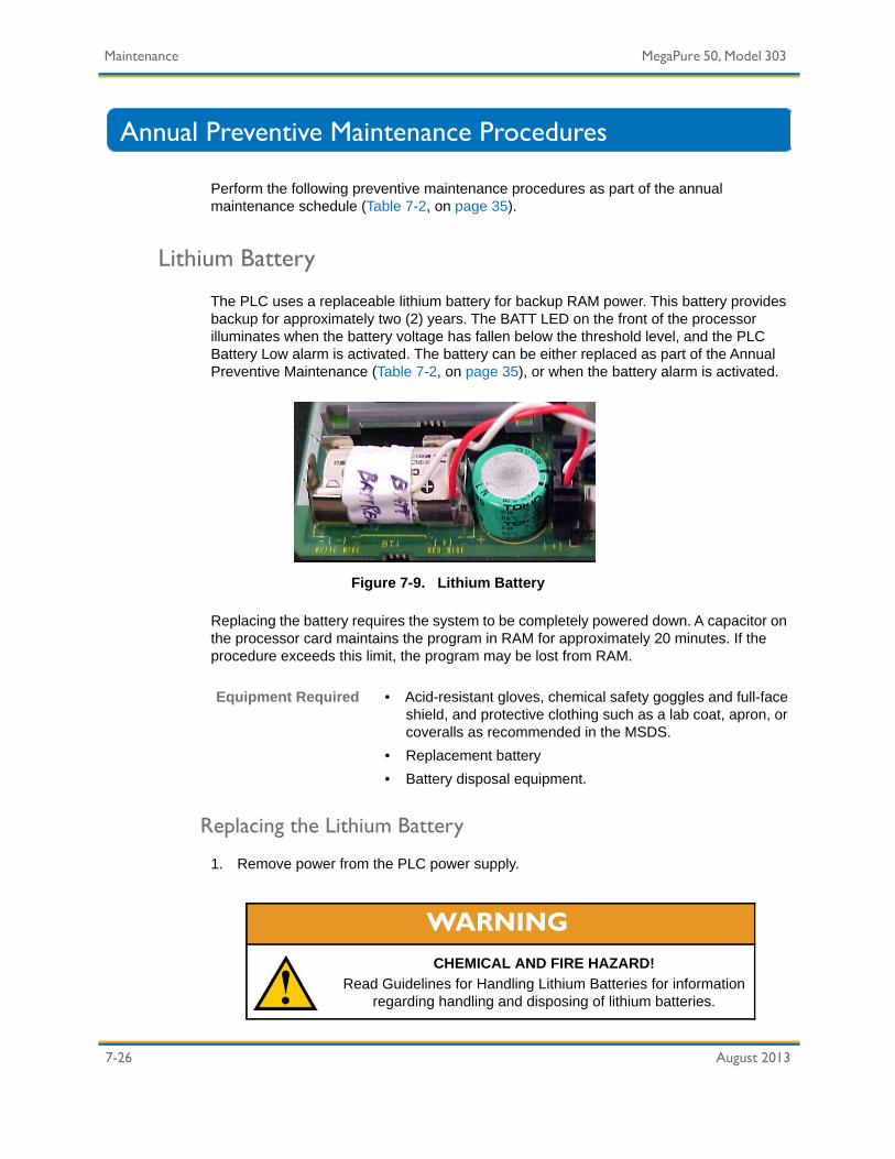
7-26 August 2013
Maintenance MegaPure 50, Model 303
Annual Preventive Maintenance Procedures
Perform the following preventive maintenance procedures as part of the annual maintenance schedule (Table 7-2, on page 35).
Lithium Battery
The PLC uses a replaceable lithium battery for backup RAM power. This battery provides backup for approximately two (2) years. The BATT LED on the front of the processor illuminates when the battery voltage has fallen below the threshold level, and the PLC Battery Low alarm is activated. The battery can be either replaced as part of the Annual Preventive Maintenance (Table 7-2, on page 35), or when the battery alarm is activated.
Figure 7-9. Lithium Battery
Replacing the battery requires the system to be completely powered down. A capacitor on the processor card maintains the program in RAM for approximately 20 minutes. If the procedure exceeds this limit, the program may be lost from RAM.
Replacing the Lithium Battery
1. Remove power from the PLC power supply.
Equipment Required • Acid-resistant gloves, chemical safety goggles and full-face shield, and protective clothing such as a lab coat, apron, or coveralls as recommended in the MSDS.
• Replacement battery• Battery disposal equipment.
WARNINGCHEMICAL AND FIRE HAZARD!
Read Guidelines for Handling Lithium Batteries for information regarding handling and disposing of lithium batteries.

MegaPure 50, Model 303 Maintenance
August 2013 7-27
a. Obtain authorization to shut the system down.
b. Toggle the A/C disconnect switch to Off.
c. Lockout/tagout the A/C disconnect switch.
2. Remove and replace the battery.
3. Dispose of the battery (refer to Disposing the Lithium Battery (page 7-27)).
4. When all maintenance procedures are complete, restore power to the PLC power supply.
a. Remove the lockout/tagout devices.
b. Toggle the A/C disconnect switch to On.
c. Start up the system.
5. If the system does not start up correctly, repeat procedures to ensure connections are routed correctly.
Disposing the Lithium Battery
The PLC provided on the MegaPure 50, Model 303 is supplied with a lithium battery that must be replaced it becomes depleted. Carefully inspect the depleted battery casing for damage and/or signs of electrolyte leakage.
NOTICEREMOVE POWER FROM THE SYSTEM!
Do not remove the processor from the PLC chassis until all power is removed from the PLC power supply.
WARNINGFIRE HAZARD!
Do not incinerate or dispose batteries in general trash collection. They may explode or rupture.
Check state and local regulations dealing with the disposal of lithium or nickel cadmium batteries. You are legally responsible
for the hazards created by improper battery disposal.

7-28 August 2013
Maintenance MegaPure 50, Model 303
Replacing the Filters
Filters catch large particles being pumped through systems. An indication of clogged filters is an increase in differential pressure.
Cartridge change-out can now be done with minimal contact to the used cartridge. Mykrolis’ Chemlock cartridges are locked into the bowl with a 1/4-turn. By turning the locking ring, the cartridge is pushed securely into the housing head; the cartridge cannot be dislodged during operation.
For cartridge removal, do not grab the cartridge body, simply unscrew the locking ring and the cartridge will disengage from the housing head. This minimizes exposure to chemicals.
1. Wear the proper PPE. Refer to the MSDSs and site regulations.
2. Turn the main power AC disconnect switch to the Off position and proceed with local lockout/tagout procedures.
3. Close MV7 and MV9.
4. Lockout denotes using an apparatus to prevent manual valve operation.
5. Open MV6 and allow to gravity drain for one minute.
6. Replace FL1 and close MV6. Use hand sprayer to clean or remove any chemical still visible in the cabinet interior.
Equipment Required • MSDS for all system chemistry.• PPE required by site and recommended on MSDS, including,
but not limited to: protective clothing, eye shields, gloves, and hearing protection.
• Chemical absorbent pads and wipes, and other safety equipment as recommended on the MSDS.
• Lockout/Tagout Equipment.• Appropriate chemical waste container as recommended on
MSDS.• Container (1 liter or larger) for the filters.• Auxiliary lighting.
WARNINGCHEMICAL HAZARD!
The exhaust effluent may contain chemical (vapor or liquid). Handle and treat to comply with safety and pollution control
regulations. Supplemental exhaust may be required for maintenance tasks.

MegaPure 50, Model 303 Maintenance
August 2013 7-29
7. Insert the cartridge into the bowl.
8. Twist the filter 1/4-turn to lock.
9. Attach the bowl to the head.
10. Tighten the locking ring to seat the double O-rings. Use a housing wrench to ensure proper tightening.
11. Remove lockout apparatus and open MV7 and MV9.
Note: Filters are mounted with the bowl up on slurry systems and with the bowl down on chemical systems.

7-30 August 2013
Maintenance MegaPure 50, Model 303
Pulsation Dampener
Dampeners require very little maintenance. There is no need for lubrication. However, the PTFE bellows must be replaced every second time the diaphragms in the pumps are replaced. As with any pumping system, wear is dependent on many factors including material, temperature, chemicals, fluid abrasiveness, and system design.
Periodic inspection of the dampeners and fasteners should be conducted to visually check for signs of over-pressurization, fatigue, stress, or corrosion. Body housings and fasteners must be replaced at first indication of deterioration.
After the initial torque of fasteners, bolts will usually lose up to 20% of their strength when re-torqued. Failure to replace both nuts and bolts upon re-assembly will void the pulsation dampener product warranty.
CAUTIONREPLACE NUT AND BOLT FASTENERS
Replace nut and bolt fasteners at each re-assembly with fasteners of equal grade/strength value.
Do not re-use old nuts and bolts.
CAUTIONDO NOT USE IF FASTENERS CORRODED
Do not use the dampener if the fasteners (nuts and bolts) are corroded. Check for fastener corrosion frequently, especially in
atmospheres containing salt or corrosive chemicals, or if dampener leakage has occurred.

MegaPure 50, Model 303 Maintenance
August 2013 7-31
EMO Testing
The EMO provides the operator with a means to shut down the system in emergency situations. Activating the EMO shuts the system down and disrupts distribution.
Figure 7-10. Emergency Machine Off (EMO) Button
1. Wear acid-resistant gloves, chemical safety goggles and full-face shield, and protective clothing such as a lab coat, apron, or coveralls as recommended in the MSDS.
2. Press the EMO button. Ensure the system completely powers down.
3. Restart the system.
Equipment Required • MSDS for all system chemistry.• Acid-resistant gloves, chemical safety goggles and full-face
shield, and protective clothing such as a lab coat, apron, or coveralls as recommended in the MSDS.
- OR -

7-32 August 2013
Maintenance MegaPure 50, Model 303
Completing Preventive Maintenance Procedures
Perform the following preventive maintenance procedures as part of the Completing Preventive Maintenance schedule (Table 7-2, on page 35).
Cabinet Cleaning
Clean the cabinet after all other PM procedures are completed. Cabinet cleanliness is necessary for accurate visual inspections.
Cleaning the cabinet requires opening the s and taking proper precautions to avoid chemical and electrical hazards. Follow all site-specific procedures during the cabinet cleaning.
1. Wear acid-resistant gloves, chemical safety goggles and full-face shield, and protective clothing such as a lab coat, apron, or coveralls as recommended in the MSDS.
2. Rinse all chemical residue from the cabinet interior using the hand sprayers or wipes saturated in 10% IPA solution.
3. Thoroughly dry the cabinet interior.
4. Wipe the cabinet exterior clean.
5. Dispose of all wipes according to site requirements and MSDS recommendations.
NOTICECLEAN THE CABINET LAST!
Cleaning the front of the cabinet and the s should be completed after all other PM procedures are done to avoid repeating the procedure.
Equipment Required • MSDS for all system chemistry.• Acid-resistant gloves, chemical safety goggles and full-face
shield, and protective clothing such as a lab coat, apron, or coveralls as recommended in the MSDS.
• Chemical absorbent pads and wipes, and other safety equipment as recommended on the MSDS.
• Appropriate chemical waste container as recommended on MSDS.
• Auxiliary lighting.• DI water or 10% IPA solution.

MegaPure 50, Model 303 Maintenance
August 2013 7-33
Maintenance Forms
The following is a list of the forms included in this section:
• Work Order Form
• Preventive Maintenance Form
• Device Settings Record Sheet

7-34 August 2013
Maintenance MegaPure 50, Model 303
Work Order Form
The following example can be used for notifying and scheduling system service.
Table 7-1. Work Order Form Example
Work Order #: System ID:Location: Serial Number:Technician: Chemical:Start Date: End Date:Frequency (circle one): Weekly/Monthly/Quarterly/Semiannual/Annual

MegaPure 50, Model 303 Maintenance
August 2013 7-35
Preventive Maintenance Form
The preventive maintenance form is a comprehensive list which includes all recommended preventive maintenance items. The list is divided into weekly, monthly, quarterly, semiannual, and annual sections. As each item in the list is completed, record any values or comments in the Comments column. Record any values or comments in the Comments column. Initial each item in the list as it is completed. When the preventive maintenance is complete, follow the instructions for returning the equipment to Automatic operation. Obtain the appropriate signatures, as required, by site-specific policies and procedures.
Table 7-2. Preventive Maintenance List
Preventive Maintenance Task Comments InitialsWeekly1. Complete the Visual System Inspection procedure.
Record all issues. 2. Check all system Device Settings. Refer to the Device
Settings List. Investigate and record any deviations from normal settings.
3. Go to Completing Preventive Maintenance in this form to complete weekly preventive maintenance steps.
Monthly1. Complete pump maintenance.
a. Pump P1 operation.b. If required, repair, replace or schedule pump
maintenance.2. Check the leak detectors for proper operation. Adjust
sensors as needed.3. Go to Completing Preventive Maintenance in this form
to complete monthly preventive maintenance steps.Quarterly1. Verify operation of all critical alarms.2. Check operation of regulators, pressure switches, relief
valves, and flow regulators.3. Go to Completing Preventive Maintenance in this form
to complete quarterly preventive maintenance steps.Semiannual1. Tighten all system fittings. Refer to Fittings (page 7-22).
a. Record loose fittings.b. Repair or replace leaking fittings or schedule
maintenance. Record fittings repaired or replaced.2. Rebuild pump P1. Refer to Rebuilding Pumps (page 7-
24). If 2nd diaphragm rebuild, replace PTFE bellows in Pulsation Dampener also.

7-36 August 2013
Maintenance MegaPure 50, Model 303
3. Go to Completing Preventive Maintenance in this form to complete semi-annual preventive maintenance steps.
Annual1. Replace lithium battery. Refer to Lithium Battery
(page 7-26).2. Replace filter(s). Refer to Replacing the Filters (page 7-
28).3. Inspect Pulsation Dampeners and fasteners to visually
check for signs of over-pressurization, fatigue, stress, or corrosion. Replace body housings and fasteners at first indication of deterioration. Refer to Pulsation Dampener (page 7-30).
4. Verify operation of EMO. Refer to EMO Testing (page 7-31).
5. Go to Completing Preventive Maintenance in this form to complete annual preventive maintenance steps.
Completing Preventive Maintenance1. Clean front of cabinet and s. Use DI water or 10% IPA
solution only. Refer to Cabinet Cleaning (page 7-32).2. Close the cabinet doors and electrical hood.3. Cancel the alarm bypass if activated.4. Ensure the system is ready for Automatic operation.5. Return the system to Automatic operation.Preventive Maintenance Sign-offPersonnel Signature DateTechnician 1:Technician 2:Supervisor:
Table 7-2. Preventive Maintenance List (continued)
Preventive Maintenance Task Comments Initials

MegaPure 50, Model 303 Maintenance
August 2013 7-37
Device Settings Record Sheet
Work Order #:System: Serial Number:Technician: Chemical:Start Date: End Date:
Table 7-3. Device Reference List
P&ID Location
Type Number State Description Initials
1/F6 AV 1 NC Valve, Diaphragm, Pneumatic,2-way, Chemical Discharge Isolation
1/C6 AV 2 NC Valve, Diaphragm, Pneumatic, 2-way, Filter Degassing Isolation
1/C10 AV 3 NC/NO Valve, Diaphragm, Pneumatic, 3-way, Pump Pneumatic Supply Selection
1/D15 AV 4A NC Valve, Diaphragm, Pneumatic, 2-way, Drum #1 Isolation
1/D14 AV 4B NO Valve, Diaphragm, Pneumatic, 2-way, Drum #2 Isolation
1/F12 AV 5 NC Valve, Diaphragm, Pneumatic, 2-way, Drum Blanket Isolation
2/G15 BV 1 Closed Valve, Ball, 2-way, N2 Supply Isolation2/G10 BV 2 Closed Valve, Ball, 2-way, CDA Supply Isolation2/H14 BV 7 Closed Valve, Ball, 2-way, Z-Purge Isolation1/D10 Dampener #1 ----- Dampener, Pulsation, Pump P11/A15 Drum #1 ----- Drum, Chemical Supply, Principle1/A14 Drum #2 ----- Drum, Chemical Supply, Redundant1/D7 FL 1 ----- Filter, Principle2/F13 FR 1 Field Set Flow Regulator, Manual, Pneumatic
Compartment Purge2/F12 FR 2 Field Set Flow Regulator, Manual, Drum Blanket2/H12 FR 7 Field Set Flow Regulator, Manual, Z-Purge1/A9 LD 1 NC Sensor, Leak, Process Cabinet
1/D13 LS 1 NO Sensor, Proximity, Drum Empty1/E6 LS 2 NO Sensor, Proximity, Filter Degassing Line
1/C15 MV 1A Closed Valve, Diaphragm, Manual, 2-way, Drum #1 Supply Isolation
1/C14 MV 1B Closed Valve, Diaphragm, Manual, 2-way, Drum #2 Supply Isolation

7-38 August 2013
Maintenance MegaPure 50, Model 303
1/B12 MV 2 Closed Valve, Diaphragm, Manual, 2-way, Pump P1 Inlet Isolation
1/E10 MV 3 Closed Valve, Diaphragm, Manual, 2-way, Pump P1 Exit Isolation
1/B11 MV 4 Closed Valve, Diaphragm, Manual, 2-way, Pump P1 Drain Isolation
1/F7 MV 5 Closed Valve, Diaphragm, Manual, 2-way, Filter FL1 Vent Isolation
1/C7 MV 6 Closed Valve, Diaphragm, Manual, 2-way, Filter FL1 Drain Isolation
1/E9 MV 7 Closed Valve, Diaphragm, Manual, 2-way, Filter FL1 Inlet Isolation
1/G6 MV 9 Closed Valve, Diaphragm, Manual, 2-way, Chemical Supply Isolation
1/C11 P 1 ----- Pump, Chemical Dispense, Principle2/D14 PG 1 ----- Gauge, N2 Supply to Solenoids2/F14 PG 2 ----- Gauge, N2 Supply to Drum Blanket2/G9 PG 3 ----- Gauge, CDA Supply to Pump P11/E5 PG 4 ----- Gauge, Filter FL1 Exit Pressure Indicator1/E8 PG 5 ----- Gauge, Filter FL1 Inlet Pressure Indicator1/F10 PG 6 -1" H2O Gauge, Vacuum, Exhaust2/H13 PG 7 ----- Gauge, Pressure, Z-Purge2/C14 REG 1 70 PSIG Regulator, Pressure, N2 Supply to Solenoids2/F14 REG 2 1 PSIG Regulator, Pressure, N2 Supply to Drums2/G9 REG 3 60 PSIG Regulator, Pressure, CDA Supply to Pump P12/H13 REG 7 4" H2O Regulator, Pressure, CDA Supply to Z Purge
Line2/D13 RV 1 80 PSIG Relief Valve, N2 Supply to Solenoids
Overpressure2/F12 RV 2 2 PSIG Relief Valve, N2 Drum Blanket Overpressure2/G7 RV 3 70 PSIG Relief Valve, Pump P1 Pneumatic Supply
Overpressure2/H5 RV 7 3 PSIG Relief Valve, Z-Purge Line
Table 7-3. Device Reference List (continued)
P&ID Location
Type Number State Description Initials

August 2013 8-1
Chapter 8: Schematics
This chapter contains the following information:
Legend ...................................................................................................9-3P&ID Schematic......................................................................................9-5Electrical Schematic ...............................................................................9-7Facility Schematic...................................................................................9-8

8-2 August 2013
Schematics MegaPure 50, Model 303

MegaPure 50, Model 303 Schematics
August 2013 8-3
Legend
DESCRIPTION
CHG 003-UPDATE BORDER WITHNEW LOGO
NOTES: UNLESS OTHERWISE SPECIFIED
Navigation Key:
#
SHEET NUMBER
GRID NUMBER
NOTE NUMBER
DATE
3 2 15 4678910111213141516
E
D
C
B
A
F
G
H
3 2 15 4678910111213141516
E
D
C
B
A
F
G
H
REV ECO DRAWN BY DATE
003 CP32775 FCB 07/17/12
OF
REF
DWG NO
ENGINEER
SIZE
TITLE
REV
FILE SHEET
UNLESS OTHERWISE SPECIFIED:ALL DIMS IN MM [INCHES].DO NOT SCALE DRAWING.
P AND ID,LEGEND,MEGA SBD
T.GRAVES 02/12/08
343-00003-0001 2003
101819
B
7/17/2012 6:51:35 AM
BASIC VALVE
ACTUATORS
MANUAL
PNEUMATIC
EXAMPLE
VALVE, 3 WAY, DIAPHRAM,PNEUMATICALLY OPERATED
2 WAY
3 WAY
4 WAY
CONFIGURATION
GATE
DIAPHRAGM
BALL
GLOBE
TYPE
SPECIALTY VALVES
CHECK
BALL CHECK
NEEDLE
RELIEF
FLOW CONTROL
TANKS/VESSELS
PUMPS
CENTRIFUGAL
DIAPHRAGM
TANK COMPONENTS
VB
DRUM
TANK
FILTER
VESSEL
SPARGER
SPRAY HEAD
VORTEX BUG
REGULATOR
ACTUATORS
MANUAL
EXAMPLE
REGULATOR, REDUCING,SELF CONTAINED, HANDADJUSTED, PRESSUREINDICATOR
REDUCING,SELFCONTAINED
CONFIGURATION
PI
BACK PRESSURE,SELF CONTAINED
REDUCING,LINE SENSING
BACK PRESSURE,LINE SENSING
PRESSURE
INDICATORS
PI
DI GUN
COMPONENTS
DE-GASSINGTEE
SAMPLE DRAIN
SUMP
DISCRETEINSTRUMENT
DIAPHRAGM
1" TF
-
-
-
PAGE SYMBOLS
LINE FUNCTIONDIAMOND
OFF PAGECONNECTOR
SPECIAL NOTE
-
REV
P = PURGE F = FLUSH
LINE SYMBOLS
FUNCTIONDIAMOND
JUNCTION
FLOW ARROW
-
P = PURGE F = FLUSH
MISCELLANEOUSSYMBOLS
CAP
REDUCER
DOUBLECONTAINMENT
QUICKCONNECT
HALFCOUPLING
SKIN TOP
BULKHEAD
PROCESSDIRECTION ARROW
SIZE BUBBLE
DAMPNER
PNEUMATIC COMPONENT
SOLENOIDVALVE
STATICMIXER
STRAINER
MECHANICALMIXER
VENTURI
STROKE LIMITERS
LIMIT OPEN
LIMIT CLOSED
PERISTALTIC

Schematics MegaPure 50, Model 303
8-4 August 2013
NOTES: UNLESS OTHERWISE SPECIFIED
Navigation Key:
#
SHEET NUMBER
GRID NUMBER
NOTE NUMBER
DWG NOSIZE
TITLE
REV
SHEET
3 2 15 4678910111213141516
E
D
C
B
A
F
G
H
3 2 15 4678910111213141516
E
D
C
B
A
F
G
H
OF
REV ECO DRAWN BY DATE
003 CP32775 FCB 07/17/12
P AND ID,LEGEND,MEGA SBD
343-00003-0002 2003B
INTERNAL SYSTEM LINK (SOFTWARE OR DATA LINK)
ELECTRIC BINARY SIGNAL
PNEUMATIC BINARY SIGNAL
ELECTROMAGNETIC OR SONIC SIGNAL (NOT GUIDED)
ELECTROMAGNETIC OR SONIC SIGNAL (GUIDED)
OPTIONAL BINARY SYMBOLS
MECHANICAL LINK
CAPILLARY TUBE
HYDRAULIC SIGNAL
ELECTRIC SIGNAL
PNEUMATIC SIGNAL
UNDEFINED SIGNAL
INSTRUMENT SUPPLY OR CONNECTION TO PROCESS
LINE TYPE DESCRIPTION
(ON-OFF)
A ALAYTICALB BLENDC CHEMICALD DRAINE USER CHOICE
G CDAH HUMIDIFIED N2K TEMPERATURE CONTROLM METROLOGYN N2P IPWQ SAMPLE
T TITRATORW DI WATER
S SLURRY
F
PROCESS DESIGNATOR
FILTRATION
INSTRUMENT SYSMBOLS
FUNCTION
DISCRETEINSTRUMENT
CONFIGURATION
SHARED DISPLAYSHARED CONTROL
COMPUTERFUNCTION
PROGRAMMABLELOGIC CONTROLLER
FIELD MOUNTED
PRIMARY LOCATION,NORMALLY ACCESSABLE TOOPERATOR
PRIMARY LOCATION,NORMALLY INACCESSABLETO OPERATOR
AUXILLARY LOCATION,NORMALLY INACCESSABLETO OPERATOR
AUXILLARY LOCATION,NORMALLY ACCESSABLE TOOPERATOR
EXAMPLE
INSTRUMENT, SHARED DISPLAY,PRIMARY LOCATION, ACCESSIBLE TOTHE OPERATOR
TYPICAL AV CONTROL SCHEME
AV PNEUMATIC VALVE
MV MANUAL VALVE
CV CHECK VALVE
FR FLOW REGULATOR
LS* LEVEL, SENSOR
YS PRESENCE, SENSOR
FE FLOW ELEMENT
PR PRESSURE REGULATORPRV PRESSURE RELIEF, VALVEPT PRESSURE TRANSMITTER
FT FLOW TRANSMITTER
COMPONENT DESIGNATOR
WT WEIGHT TRANSMITTER
FI FLOW INDICATOR
PI PRESSURE INDICATORPE PRESSURE ELEMENT
HV HAND VALVE
SV SOLENOID VALVE
PC PRESSURE CONTROLLER
DESIGNATION EXPANSION
XXXXXX
XXXXXXXXXXX
XXXX
XXXX
FC FLOW CONTROLLER
QI QUANTITY, INDICATOR
TA* TEMPERATURE ALARM
SI SPEED INDICATORSC SPEED CONTROLLER
AI ANALYSIS INDICATOR
ADDED IF MORE THAN ONE COMPONENTDESIGNATION APPLY
PCV PRESSURE CONTROL VALVE
*H(HIGH),HH(HIGH/HIGH) L(LOW),LL(LOW/LOW)
AIRSUPPLY

MegaPure 50, Model 303 Schematics
August 2013 8-5
P&ID Schematic

Schematics MegaPure 50, Model 303
8-6 August 2013

MegaPure 50, Model 303 Schematics
August 2013 8-7
Electrical Schematic
NEU
+24VDC
4
0VDC
5
-4
3C
GND
-3C
(14) (11)
CR201-3E
BRN-5
SW1EMO
3B-3A
VIO-3B
VIO2.5 AMP
FU-2VIO-3
HOT-L1
14AWG,BLK1.8 AMP
FU-1-1B
BLK
2.5A
24VDC
PWR 1
INTERLOCK
3C
ADDITIONALREMOTE EMO
3D
START
5-5-3F-3E
3E 3F
3C
(F)
(A)CR1A
CR1
PB1
GRN/YEL
-N14AWG,WHT
L1
N -NIN120VAC
VIO
-3C VIO
VIO VIO VIO VIO
ORG
OVERRIDE
3FG
-55
-5 BRN
-5 BRN
BRN-3F-3E
(B)(E)
-3FVIO
BRN
RED
(1)
SW2A
RED
VIO
BLK
VIO
SW2B
RED RED RED
ORG
(2) (3) (4)
CR1B3E
VIO31
2 4ISB1
14AWG,WHT
14AWG
-3E
BLK
-3D
VIO
-3DI
RED
GRN/YEL14AWG
SW2
ORG
GRN/YEL
-L1
14AWG,BLK
G
GRN/YEL14AWG
L1
-L114AWG,BLK
SUPPR1
GB1GB1
GB1
(G)(H)
NOTES: UNLESS OTHERWISE SPECIFIED
1ALL WIRES 18AWG UNLESSOTHERWISE SHOWN
2 (#) DENOTES CONNECTORTERMINAL DESIGNATION
3 ALL FUSES 250VAC RATED
KEYED NOTES:
JUMPER TO BE REMOVED WHENINSTALLING ADDITIONAL(OPTIONAL) EMO
DESCRIPTION
-REMOVED ISB2 FROM SCHEMATIC-CORRECTED COIL TERMINALCALL-OUTS ON CR1
OF
REF
DWG NO
ENGINEER
SIZE
TITLE
REV
FILE SHEET
DATE
3 2 15 4678910111213141516
E
D
C
B
A
F
G
H
3 2 15 4678910111213141516
E
D
C
B
A
F
G
H
REV ECO DRAWN BY DATE
003 CP35840 DAB 8/1/13
UNLESS OTHERWISE SPECIFIED:ALL DIMS IN MM [INCHES].DO NOT SCALE DRAWING.
SCHEMATIC, ELECTRICALMEGAPURE 50, MODEL 303
----
D. BECK 3/15/13
217-00494-0001 2003
--
B
8/1/2013 9:56:02 AM
1
1
003
003

Schematics MegaPure 50, Model 303
8-8 August 2013
0/11
-211BLUGBRN
BLU -210A
0/10
G -209BLU 0/9
BLU -208BLU 0/8
-4VIO
BLK -207RED 0/7
-206 0/6
-205 0/5
BLK -204RED 0/4
-4VIO
ABRN -203BLU
GBRN -202BLU
-4VIO
0/0
VDC
GRN/YEL
-5BRN
+ 24V -
1/1 BLU-101
1/2 BLU-102
1/3 BLU-103
VIO-4
1/4 BLU-104
1/5 BLU-105
1/6 BLU-106
1/7 BLU-107
1/8 BLU-108
1/9 BLU-109
1/10
BLU-110
1/11
BLU-111
1/12
BLU-112
1/13
BLU-113
1/14
1/15
1/16
1/17
1/18
1/19
1/0 BLU-100 BRN
NOT
USE
NOT
USE
COM
DC
DC IN
VAC
0/1
VAC
VDC
0/2
VDC
VAC
0/3
VAC
VDC
VAC
VDC
COM
DC
OUTPUTS
INPUTS
100 BLU
101 BLU
102 BLU
103 BLU
BRN
BRN
105
104
111
110
109
108
(1)
(2)
RED
WHT
112
113
BLU BRN
SHD (4)
REDBLK
REDBLK
BRN
BRN
VIO -4
0V24VDC
SW3
PB3
PB4
PB5
MAINT/AUTO
SILENCE
RESET
START DRUM
LD1A
LD1 CABINET LEAK
CHEM DEMAND CR107
DRUM EMPTYPB6
CHEM DISPENSE
SONALERT
EV3
EV4
START DRUM
RESET
EV2
EV1
SILENCE
EMPTY DRUM
-5
-4VIO -5
BRN
-5
-5
-5
BLU
BLU
-104
-105
-5
-5
-5
-5
-5
-5
-5
-5
-5
-5
-
-4 VIO
(A2) (A1)
(A2) (A1)INTERLOCK OVERRIDE CR201
HANDSHAKE OUT CR200
(11) (14)
SW1A DRUM A BLU-108
-109
-110
-5 BRN
BRN-5
-100
-101
-102
-103
+
CR200
CR201
VIO-4
SELECTED
BRN-5
BLUSW1B SELECTEDDRUM B
-200
-201
(OPTIONAL)
CR200
(11) (14)
SIGNAL TO CUSTOMER
-4VIO
VIO -4
250251
SIGNAL FROM CUSTOMER
CR107158
(A1) (A2)
157
-5 BRN
N/C
A
-5 BRN
XOO
OOX
106BLU-106
CR107
3 1
24
RED
WHT
BLK
LD1B
VIO-4
BRN-5
BLU-106
(1)
(2)
RED
WHT
BLK (4)
LS2A
LS2 FILTER BURP
N/O
3 1
24
RED
WHT
BLK
LS2B
VIO-4
BRN-5
BLU-105
(1)
(2)
RED
WHT
BLK (4)
LS1A
LS1 DRUM EMPTY
N/O
3 1
24
RED
WHT
BLK
LS1B
VIO-4
BRN-5
BLU-104
ISB3
ISB4
ISB5
PLC POWER
GB1
BLK-111
PS2
BRN-4
BLU-5
PS2LOW PRESSURE TO CABINETPOSITIVE PRESSURE
NOTES: UNLESS OTHERWISE SPECIFIED
1ALL WIRES 18AWG UNLESSOTHERWISE SHOWN
2 (#) DENOTES CONNECTORTERMINAL DESIGNATION
3 ALL FUSES 250VAC RATED
KEYED NOTES:
CLOSED CONTACTS = AUTOMODEOPEN CONTACTS = AUTOSWITCHING
OF
DWG NOSIZE
TITLE
REV
SHEET
3 2 15 4678910111213141516
E
D
C
B
A
F
G
H
3 2 15 4678910111213141516
E
D
C
B
A
F
G
H
REV ECO DRAWN BY DATE
003 CP35840 DAB 8/1/13
SCHEMATIC, ELECTRICALMEGAPURE 50, MODEL 303
----
217-00494-0002 2003B
2
2
3
3

MegaPure 50, Model 303 Schematics
August 2013 8-9
Facility Schematic

Schematics MegaPure 50, Model 303
8-10 August 2013

August 2013 9-1
Chapter 9: Parts List
Part Number Part Description QtyValves101-25024-000 VLV, MAN, BALL, 3/8 COMP, SST 1101-25024-000 VLV, MAN, BALL, 3/8 COMP, SST 2101-25026-000 VLV, PRESS RELIEF, 3-50PSI,1/4, SST 1101-25027-000 VLV, PRESS RELIEF, 50-150PSI, 1/4, SST 1101-25027-000 VLV, PRESS RELIEF, 50-150PSI, 1/4, SST 1101-34488-000 VALVE, PRESS RELIEF, 1/4” MNPT POP-OFF, SST, 10PSIG 1370-00500-000 VLV, AOV, 3-WAY DIAPH W/VI, 1/4OR x 3/8FLR, FURON UPM 1370-22071-000 VALVE ASSY, SOLENOID, 1/8” 4370-25011-000 VLV, AOV, 2-WAY, 3/4 FLR, PFA 1370-25068-000 VLV, MAN, 3/4 FLR, PFA 6370-25068-000 VLV, MAN, 3/4 FLR, PFA 1370-25102-000 VLV, MAN, 2-WAY 3/8 FLR, PFA 2370-25144-000 VLV,CHECK, 3/8 FLR, PTFE 1370-25191-000 VLV, AOV, 2-WAY 3/8 FLARE, PFA 2370-25195-000 VLV, AOV, 2-WAY, 3/4 FLR, PFA 2Hardware104518 MAGNEHELIC,DIFF PRESS,0-3,H20 1107-30672-000 DISPLAY, PRESS SNSR, POS, 0-1 MPA, 2 NPN, 1/8” NPT 1103-31581-000 MEDIA, FILTER, CARTRIDGE, 0.05UM, PFA, EXTENDED CAP END,
KALREZ 222 O-RINGS1
120-31380-000 SENSOR, LEVEL, PHOTOELECTRIC, 1/4” TO 1" 1121-22009-000 SNSR, REED, FLG MNT, 6' LEAD, NO 2380-25016-000 PULSE DAMPER, 1, STR/ELB, PFA, 1380-25024-000 PUMP, BELLOWS, ASTI PFD2-316U (U=KALREZ O-RING), 0-5 GPM, 3/
4” FLR I/O, KALREZ SEALS1
381-22065-000 FLM, PNLMT, 1/8”, ACRYL, 4-30 SCFH 2381-25036-000 FLWMTR, PNLMT, 1/4”, ACRYL, 2-20 SCFM 1Electrical120-25386-000 SENSOR, LEAK DETECT, PFA ENCAP, PAPERLESS 1120-22413-000 FUSE, REJECTION, 1.8 AMP 1120-25494-000 FUSE, FLM, 2.5 AMP 1120-32013-000 POWER SUPPLY, 24VDC, 2.5A, DIN RAIL MOUNT, CE, RoHS 1120-34506-000 SURGE PROTECTOR, 120VAC 1
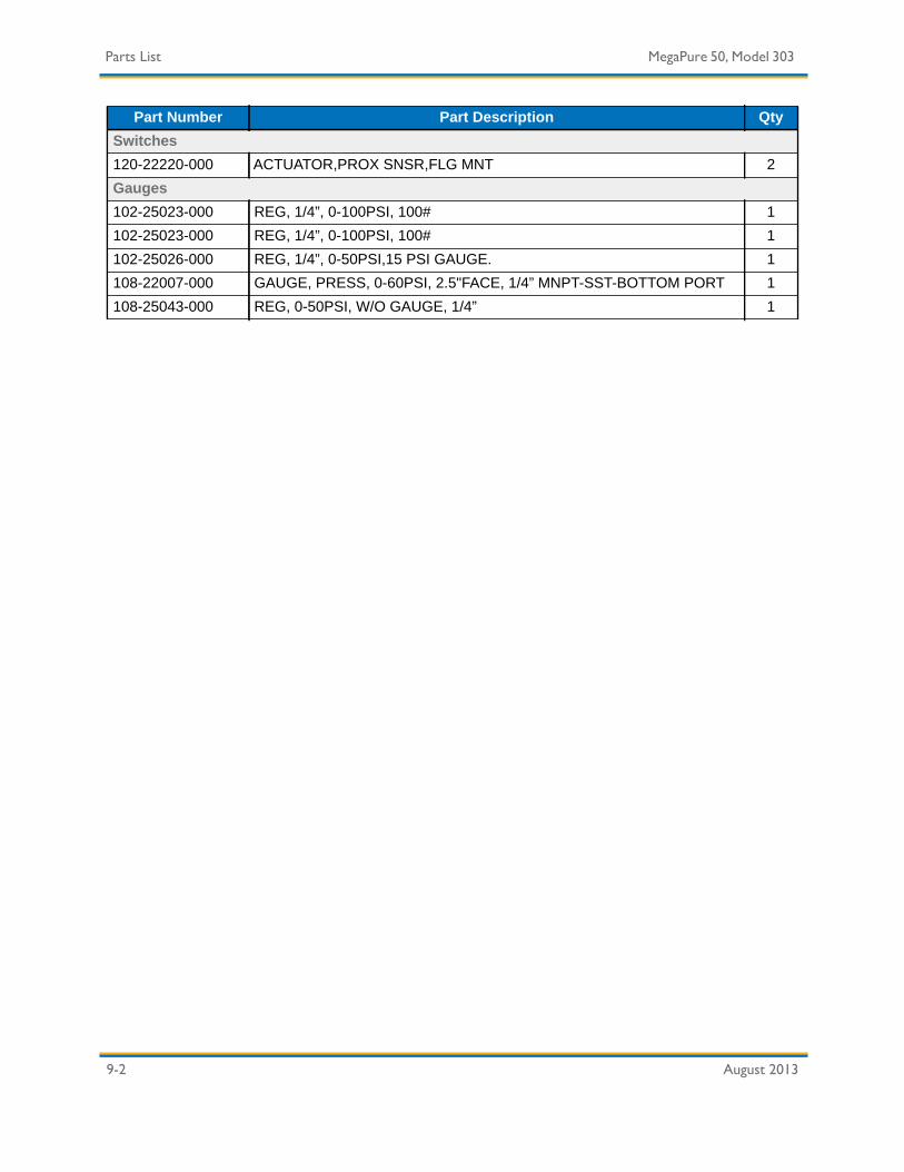
9-2 August 2013
Parts List MegaPure 50, Model 303
Switches120-22220-000 ACTUATOR,PROX SNSR,FLG MNT 2Gauges102-25023-000 REG, 1/4”, 0-100PSI, 100# 1102-25023-000 REG, 1/4”, 0-100PSI, 100# 1102-25026-000 REG, 1/4”, 0-50PSI,15 PSI GAUGE. 1108-22007-000 GAUGE, PRESS, 0-60PSI, 2.5"FACE, 1/4” MNPT-SST-BOTTOM PORT 1108-25043-000 REG, 0-50PSI, W/O GAUGE, 1/4” 1
Part Number Part Description Qty

August 2013 Glossary - 1
Glossary
A-B — Allen-Bradley Company, Inc.
ABPR — Automatic Back Pressure Regulator. The ABPR system regulates the slurry pressure in the global loop. An alternate method of controller back pressure is to hold the BPR valve at a constant setting while modulating a set of variable speed supply pumps.
Acid — Acid Compound that reacts with metal to evolve hydrogen, reacts with a base to form salt, dissociates in water to yield H2 ions, and has a pH of less than 7.
Al203 — Aluminum Oxide (Alumina). Also known as corundum and emery and used as an abrasive.
Alkali — Chemical substance that is soluble in water, neutralizes acids, and forms salts with them. An alkali has a pH of more than 7.
Amorphous — Lacking a crystalline structure; literally without shape. Having a random atomic arrangement without a three dimensional structure.
Analog — System or device that represents data variation by a measurable physical quality.
Active — Describes a device that is online and currently dispensing.
Aspirated Drain — System where suction facilitates thorough and rapid draining.
Atomize — To reduce to fine particles or spray.
ATRS — Auto-Titration/Replenishment System.
Automode — A station that can operate automatically.
AV — Automatic Valve.
Base — Compound that reacts with acids to form salts and has a pH of more than 7.
BCDS — Bulk Chemical Distribution System.
Blend Tank — Tank or station where different slurry or chemical components are combined and mixed in specific ratios.
BPR — Back Pressure Regulator.

Glossary - 2 August 2013
Glossary MegaPure 50, Model 303
BV — Ball Valve.
BPV — Back Pressure Valve.
CDA — Clean Dry Air.
CDU — Chemical Dispense Unit. Refers to the Mega Tote/Drum assembly that supplies slurry to the polishers.
Centipoise — Unit of measurement for viscosity (also see Poise).
CompactLogix — A PLC that controls equipment operation.
ControlNet — Communication protocol for sending and receiving data from the corresponding Megaflow systems (from PLC to PLC).
CPU — Central Processing Unit.
CSS — Chemical Safety Shutdown. A function that remotely shuts down all system operations in an emergency.
CV — Check Valve.
Data Highway Plus — Allen-Bradley communication protocol.
Day Tank — Tank to which blended chemicals are transferred prior to dispensation to the global loop.
Deionized — Substance from which all atoms or groups of atoms that have acquired an electrical charge have been removed.
Density — Measure of a quantity such as mass or electric charge per unit volume.
DeviceNet — Communication Protocol for collecting inputs from the field and sending outputs to the field (PLC to I/O).
DH+ — Data Highway Plus (Data Highway Plus for definition).
D.I. (or DI) — Deionized.
Digital — Processing, operating on, storing, transmitting, representing, or displaying data in the form of numerical digits, as in a digital computer.
Distribution Tank — Tank from which chemical is dispensed directly to a point of use system or to multiple systems via a global loop.

MegaPure 50, Model 303 Glossary
August 2013 Glossary - 3
EMO — Emergency Machine Off. A function when activated, immediately shuts all control power to output devices. Does not disconnect main power.
Ethernet — System for exchanging messages between computers on a local area network using coaxial, fiber optic, or twisted-pair cables.
EV — Solenoid Electrical Valve part identification code.
Fab — Wafer fabrication facility.
Force — Software function that allows the programmer to energize or de-energize an input or output independent of the program logic.
FRPP — Fire Resistant Polypropylene.
Global Loop — Distribution loop used to supply chemical or slurry to point of use systems.
GPM — Gallons per Minute.
GUI — Graphical User Interface.
HC — High Capacity.
Heterogeneous — Composed of parts of different kinds.
Homogeneous — Composed of parts of the same kind. This term is properly applied to a chemical element and compounds but not to mixtures or solutions.
Hydrometer — Instrument for measuring the specific gravity of liquids.
Hygrometer — Instruments for measuring relative humidity.
I/O — Hardware or software that controls the passage of information into and out of a computer or computer component.
IPA — Isopropanol Alcohol.
IPW — Industrial Process Water.
KTx Card — Allen-Bradley communication interface card.
Ladder Logic — A PLC program written in a format resembling an electrical ladder diagram.
LAN — Local Area Network. Network of personal computers and peripheral devices linked by cable and able to share resources.

Glossary - 4 August 2013
Glossary MegaPure 50, Model 303
LPM — Liters Per Minute.
l/m — Liters per Minute.
Loop — Piping system that returns to the point of dispensation.
MOS — Metallic Oxide Semiconductor.
MSDS — Material Safety Data Sheet.
MTBF — Mean Time Between Failure.
MV — Manual Valve.
N2 — Nitrogen.
NPP — Natural Polypropylene.
NPT — National Pipe Thread.
OFA — Oil Free Air.
ORP — Oxidation Reduction Potential.
Offline — Indicates the device is not running automatically and available for manual control (e.g., valves).
PanelView — Refers to Allen-Bradley PanelView operator terminals (PanelView 550, 600, 1000, etc.). PanelView operator terminals provide machine control and monitoring functions for most Mega Fluid Systems, Inc. equipment.
Pause — Describes the operational mode that temporarily stops the system blend and distribution process. Pause can be initiated automatically or manually through the touchscreen.
PFA — Perfluoroalkoxy.
pH — The acidity or alkalinity of a solution. Equal to the log of the reciprocal of the hydrogen ion concentration measured in gram moles/liter. In practical terms the pH scale extends from 0 -14.
PID — Proportional Integral Derivative. A PID controller corrects the error between a measured process variable and a desired setpoint by calculating and then outputting a corrective action that can adjust the process accordingly.
The PID controller calculation (algorithm) involves three separate parameters; the Proportional, the Integral and Derivative values. The Proportional value determines the reaction to the current

MegaPure 50, Model 303 Glossary
August 2013 Glossary - 5
error, the Integral determines the reaction based on the sum of recent errors and the Derivative determines the reaction to the rate at which the error has been changing. The weighted sum of these three actions is used to adjust the process via a control element such as the position of a control valve.
PLC — Programmable Logic Controller. Electronic device that controls machines and processes. It uses a programmable memory to store instructions and execute specific functions that include On/Off control, timing, counting, sequencing, arithmetic, and data handling.
PPE — Personal Protective Equipment.
Point of Use — Any wafer fabrication system that draws chemical from the global loop.
Poise — Unit of measurement for viscosity. Water = 0.01 poise.
POU — Point of Use.
Primary — Describes the main slurry/dispense station. The primary station contains a power disconnect, main controller and a PanelView Plus touchscreen.
PSI — Pounds per Square Inch.
PT — Pressure Transmitter.
PTFE — Polytetraflourethelene.
Pycnometer — Vessel used to measure the specific gravity of liquids or solids.
Recipe — User-defined series of steps which specifies the type (either slurry, chemical 1, chemical 2, or DI water/UPW) and amount (measured either by weight or volume) of chemical to be added to the blend/mix tank.
Repeatability — The ability of an instrument to give the same output or reading under repeated, identical conditions.
RIO — Remote I/O (also see I/O).
RV — Relief Valve.
scfm — Standard Cubic Feet per Minute.
Secondary — Describes the redundant slurry/dispense station.
Setpoint — An operational boundary or specific limit (can be either high or low) which the system is not to exceed.

Glossary - 6 August 2013
Glossary MegaPure 50, Model 303
SF — Stabilized Filtration.
SG — Specific Gravity.
SGU — Specific Gravity Units.
SLC — Small Logic Controller. Trademark of Allen-Bradley Company, Inc.
Slurry — Liquid mixture of water and an insoluble solid material.
SMS — Slurry Metrology System.
Specific Gravity — Ratio of the density of a substance to the density of water at specified conditions.
SQL — Structured Query Language. Computer language for specifying database inquiries.
SS — Stainless Steel.
Stabilized Filtration — Constant flow through the filtration loop to maximize filter effectiveness.
Standby — Describes a station or device that is started but not currently dispensing or blending.
TIP — Tool Interface Panel
Trending — Collection of system operations data for performance analysis and record-keeping purposes.
Tare — Deduction from the gross weight to allow for receptacle/packaging.
Tool — Any device, storage container, work station, or process machine used in a clean room.
UPW — Ultra-Pure Water.
Viscosity — Property of a fluid caused by molecular attraction that causes it to resist flow or movement in response to external force applied to it. Viscosity is affected by temperature.
VMB — Valve Manifold Box.
XMTR — Transmitter.

August 2013 Index - 1
IndexAABPR 10-1acid 10-1acknowledge alarm 5-5Active 10-1Al203 10-1alarms
responding to 5-5testing 7-15
alkali 10-1amorphous 10-1analog 10-1aspirated drain 10-1atomize 10-1ATRS 10-1automatic valve 7-17Automode 10-1AV 10-1
Bbase 10-1battery
lithium 7-26disposal 7-27replacement procedure 7-26
BCDS 10-1blend tank 10-1BPR 10-1BPV 10-2BV 10-2
Ccabinet 1-5
cleaning procedure 7-32cabinet cleaning 7-32caution messages
explained 2-2CDA 10-2CDU 10-2centipoise 10-2check valve 7-17Chemical 1-5chemical
exposure 2-4handling 2-4leaks 2-4spills 2-4
chemical hazard messages explained 2-3chemicals
spill mitigation 2-12cleaning
cabinet 7-32Compact 7-7compact flash card 7-7CompactLogix 10-2component
isolation and removal 7-4component troubleshooting 7-9components
electricalreplacement 7-5
ControlNet 10-2CPU 10-2CSS 10-2CV 10-2
DD.I. 10-2danger messages
explained 2-2data highway plus 10-2day tank 10-2deionized 10-2density 10-2device settings
record sheet 7-37DeviceNet 10-2DH+ 10-2DI 10-2differential pressure gauge 7-16digital 10-2distribution tank 10-2
Eelectrical
safetytype 1 hazard defined 2-5type 2 hazard defined 2-5type 3 hazard defined 2-5type 4 hazard defined 2-5work guidelines 2-5
electrical componentisolation and removal 7-5
electrical componentsreplacement 7-5
electrical components, removing 7-5electrical equipment
safety when working with 2-4electrical hazard messages explained 2-3electrical solenoid valve 7-16emergency machine off
verification procedure 7-31

Index MegaPure 50, Model 303
August 2013 Index - 2
emergency machine off (EMO) procedure 2-6EMO 10-3
circuitry description 2-7resetting an EMO button 2-7verification procedure 7-31
EMO procedure 2-6equipment
features 1-5equipment features 1-5
cabinet 1-5piping 1-5
ethernet 10-3EV 10-3
Ffab 10-3facility requirements 3-2filters
replacing 7-28fittings
inspection 7-22replacement 7-23
force 10-3FRPP 10-3
Ggas line
preventive maintenance procedure 7-22gas lines
component check 7-19global loop 10-3GPM 10-3GUI 10-3
HHC 10-3heavy object hazard messages explained 2-3heterogeneous 10-3homogeneous 10-3how to
alarmdeactivate the 5-2
alarms, test the 7-15battery, replace the 7-26, 7-27cabinet, clean the 7-32chemical startup and test 3-9components, remove 7-4DI water & leak test the system 3-8electrical components, remove 7-5EMO, test the 7-31filters, replace the 7-28fittings, check the 7-22fittings, replace the 7-23
gas line, check components of the 7-19install the system 3-3leak detector, check the 7-12manual, set to 5-3place the system 3-4prestartup test the system 3-6pump, check the 7-12pump, isolate and remove a 7-24relief valves, adjust the 7-20restart 5-5system
turn off the systemturn off the 5-3
system, configure 3-7system, start 5-2turn off alarm 5-5
hydrometer 10-3hygrometer 10-3
II/O 10-3initial system startup 5-2installation 3-1
procedure 3-3chemical startup and testing 3-9DI water startup and leak testing 3-8pre-startup testing 3-6system commissioning 3-5system configuration 3-7system inspection 3-3system location and site inspection 3-3system placement 3-4system testing 3-8
interlockssoftware
critical 6-2LD1 LEAK 6-3
warnings 6-2IPA 10-3IPW 10-3
Kkey failure points 2-10KTx card 10-3
Ll/m 10-4ladder logic 10-3LAN 10-3leak detector
check 7-12lithium battery 7-26
disposal 7-27
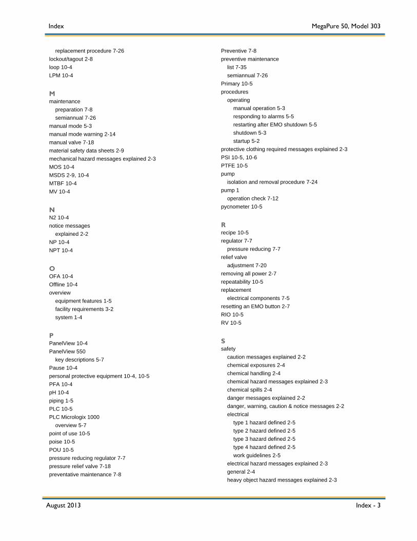
Index MegaPure 50, Model 303
August 2013 Index - 3
replacement procedure 7-26lockout/tagout 2-8loop 10-4LPM 10-4
Mmaintenance
preparation 7-8semiannual 7-26
manual mode 5-3manual mode warning 2-14manual valve 7-18material safety data sheets 2-9mechanical hazard messages explained 2-3MOS 10-4MSDS 2-9, 10-4MTBF 10-4MV 10-4
NN2 10-4notice messages
explained 2-2NP 10-4NPT 10-4
OOFA 10-4Offline 10-4overview
equipment features 1-5facility requirements 3-2system 1-4
PPanelView 10-4PanelView 550
key descriptions 5-7Pause 10-4personal protective equipment 10-4, 10-5PFA 10-4pH 10-4piping 1-5PLC 10-5PLC Micrologix 1000
overview 5-7point of use 10-5poise 10-5POU 10-5pressure reducing regulator 7-7pressure relief valve 7-18preventative maintenance 7-8
Preventive 7-8preventive maintenance
list 7-35semiannual 7-26
Primary 10-5procedures
operatingmanual operation 5-3responding to alarms 5-5restarting after EMO shutdown 5-5shutdown 5-3startup 5-2
protective clothing required messages explained 2-3PSI 10-5, 10-6PTFE 10-5pump
isolation and removal procedure 7-24pump 1
operation check 7-12pycnometer 10-5
Rrecipe 10-5regulator 7-7
pressure reducing 7-7relief valve
adjustment 7-20removing all power 2-7repeatability 10-5replacement
electrical components 7-5resetting an EMO button 2-7RIO 10-5RV 10-5
Ssafety
caution messages explained 2-2chemical exposures 2-4chemical handling 2-4chemical hazard messages explained 2-3chemical spills 2-4danger messages explained 2-2danger, warning, caution & notice messages 2-2electrical
type 1 hazard defined 2-5type 2 hazard defined 2-5type 3 hazard defined 2-5type 4 hazard defined 2-5work guidelines 2-5
electrical hazard messages explained 2-3general 2-4heavy object hazard messages explained 2-3

Index MegaPure 50, Model 303
August 2013 Index - 4
interlocks 2-13key failure points 2-10material safety data sheets 2-9mechanical hazard messages explained 2-3messages 2-2MSDS 2-9notice messages explained 2-2protective clothing required messages explained 2-3required safety precautions 2-4safety hazards explained 2-2spill mitigation 2-12warning messages 2-2warning messages explained 2-2working with electrical equipment 2-4
safety informationlockout/tagout 2-8safety components 2-15
safety interlocks 2-13scfm 10-5Schematics 8-1Secondary 10-5semiannual preventive maintenance
procedures 7-26setpoint 10-5SF 10-6SG 10-6SGU 10-6shut down system 5-3shutdown procedure 5-3SLC 10-6slurry 10-6SMS 10-6specific gravity 10-6spill mitigation 2-12SQL 10-6SS 10-6stabilized filtration 10-6Standby 10-6start manual mode 5-3starting the system 5-2startup procedure 5-2system overview 1-4
facility requirements 3-2
Ttare 10-6TIP 10-6tool 10-6trending 10-6troubleshooting
gas line 7-19turn off alarm 5-5turn system off 5-3
turn system on 5-2
UUPW 10-6
Vvalves 7-16
automatic 7-16ball 7-16check 7-16electrical solenoid 7-16flow indicator 7-16manual 7-16pressure relief 7-18relief
adjustment 7-20valves diverter 7-16viscosity 10-6VMB 10-6
Wwarning
manual mode 2-14warning messages
explained 2-2work order form 7-34