Medical electrical equipment — Part 2-12: Begrenset bruk tilgjengelig... · 2020. 4. 3. · ©ISO...
150
© ISO 2020 Medical electrical equipment — Part 2-12: Particular requirements for basic safety and essential performance of critical care ventilators Appareils électromédicaux — Partie 2-12: Exigences particulières relatives à la sécurité de base et aux performances essentielles des ventilateurs pulmonaires pour utilisation en soins intensifs INTERNATIONAL STANDARD ISO 80601-2-12 Second edition 2020-02 Reference number ISO 80601-2-12:2020(E) Begrenset bruk Levert av Standard Online AS. Kan brukes kostnadsfritt i forbindelse med Korona-krisen.
Transcript of Medical electrical equipment — Part 2-12: Begrenset bruk tilgjengelig... · 2020. 4. 3. · ©ISO...

© ISO 2020
Medical electrical equipment —Part 2-12: Particular requirements for basic safety and essential performance of critical care ventilatorsAppareils électromédicaux —Partie 2-12: Exigences particulières relatives à la sécurité de base et aux performances essentielles des ventilateurs pulmonaires pour utilisation en soins intensifs
INTERNATIONAL STANDARD
ISO80601-2-12
Second edition2020-02
Reference numberISO 80601-2-12:2020(E)
Begre
nset
bru
k
Leve
rt a
v St
anda
rd O
nlin
e A
S. K
an b
ruke
s ko
stna
dsfr
itt i
forb
inde
lse
med
Kor
ona-
kris
en.

ISO 80601-2-12:2020(E)
ii © ISO 2020 – All rights reserved
COPYRIGHT PROTECTED DOCUMENT
© ISO 2020All rights reserved. Unless otherwise specified, or required in the context of its implementation, no part of this publication may be reproduced or utilized otherwise in any form or by any means, electronic or mechanical, including photocopying, or posting on the internet or an intranet, without prior written permission. Permission can be requested from either ISO at the address below or ISO’s member body in the country of the requester.
ISO copyright officeCP 401 • Ch. de Blandonnet 8CH-1214 Vernier, GenevaPhone: +41 22 749 01 11Fax: +41 22 749 09 47Email: [email protected]: www.iso.org
Published in Switzerland
Begre
nset
bru
k
Leve
rt a
v St
anda
rd O
nlin
e A
S. K
an b
ruke
s ko
stna
dsfr
itt i
forb
inde
lse
med
Kor
ona-
kris
en.
ISO 80601-2-12:2020(E)
© ISO 2020 – All rights reserved iii
Contents
201. 1 Scope, object and related standards ...................................................................... 1
201. 1.1 * Scope ............................................................................................................................... 1 201. 1.2 Object ................................................................................................................................. 2 201. 1.3 Collateral standards ...................................................................................................... 3 201. 1.4 Particular standards ...................................................................................................... 3
201. 2 Normative references ................................................................................................ 4
201. 3 Terms and definitions ............................................................................................... 7
201. 4 General requirements ............................................................................................... 9
201. 4.3 Essential performance ................................................................................................... 9 201. 4.3.101 * Additional requirements for essential performance .................... 9 201. 4.4 Additional requirements for expected service life ................................................. 9 201. 4.6 * ME equipment or ME system parts that contact the patient ......................... 10 201. 4.11.101 * Additional requirements for pressurized gas input ................. 10 201. 4.11.101.1 Overpressure requirement ................................................................. 10 201. 4.11.101.2 Compatibility requirement ................................................................. 10
201. 5 General requirements for testing of ME equipment......................................... 11
201. 5.101 Additional requirements for general requirements for testing of ME equipment ................................................................................................................... 11
201. 5.101.1 Ventilator test conditions ................................................................... 11 201. 5.101.2 * Gas flowrate and leakage specifications ...................................... 11 201. 5.101.3 * Ventilator testing errors ................................................................... 11
201. 6 Classification of ME equipment and ME systems ............................................... 12
201. 7 ME equipment identification, marking and documents .................................. 12
201. 7.2.3 * Consult accompanying documents ................................................. 12 201. 7.2.4.101 Additional requirements for accessories ........................................ 12 201. 7.2.13.101 Additional requirements for physiological effects ...................... 12 201. 7.2.17.101 Additional requirements for protective packaging ..................... 12 201. 7.2.18 External gas source ............................................................................... 13 201. 7.2.101 * Additional requirements for marking on the outside of
ME equipment or ME equipment parts ........................................................................... 13 201. 7.4.3 * Units of measurement ....................................................................... 14 201. 7.9.1 Additional general requirements ..................................................... 14 201. 7.9.2.1.101 Additional general requirements ..................................................... 14 201. 7.9.2.2.101 * Additional requirements for warnings and safety notices ..... 15 201. 7.9.2.8.101 * Additional requirements for start-up procedure ...................... 16 201. 7.9.2.9.101 * Additional requirements for operating instructions ............... 16 201. 7.9.2.12 Cleaning, disinfection, and sterilization ........................................... 17 201. 7.9.2.14.101 * Additional requirements for accessories, supplementary
equipment, used material .................................................................................................. 17
Begre
nset
bru
k
Leve
rt a
v St
anda
rd O
nlin
e A
S. K
an b
ruke
s ko
stna
dsfr
itt i
forb
inde
lse
med
Kor
ona-
kris
en.
ISO 80601-2-12:2020(E)
iv © ISO 2020 – All rights reserved
201. 7.9.2.16.101 * Additional requirements for reference to the technical description .................................................................................................................... 18
201. 7.9.3.1.101 * Additional general requirements .................................................. 18 201. 7.9.3.101 Additional requirements for the technical description ............. 18
201. 8 Protection against electrical hazards from ME equipment ............................ 19
201. 9 Protection against mechanical hazards of ME equipment and ME systems 19
201. 9.6.2.1.101 * Additional requirements for audible acoustic energy ............. 19 201. 9.101 * Additional requirements for suction procedures ...................... 20
201. 10 Protection against unwanted and excessive radiation hazards ................... 23
201. 11 Protection against excessive temperatures and other hazards ................... 23
201. 11.1.2.2 * Applied parts not intended to supply heat to a patient ........... 23 201. 11.6.5.101 * Additional requirements for ingress of water or particulate
matter into ME equipment or ME system ....................................................................... 23 201. 11.6.6 * Cleaning and disinfection of ME equipment or ME system ....... 24 201. 11.6.7 Sterilization of ME equipment or ME system .................................. 24 201. 11.7 Biocompatibility of ME equipment and ME systems ........................................... 24 201. 11.8.101 * Additional requirements for interruption of the power
supply/supply mains to ME equipment .......................................................................... 25 201. 12 Accuracy of controls and instruments and protection against hazardous
outputs ........................................................................................................................ 27
201. 12.1 * Accuracy of controls and instruments ............................................................... 27 201. 12.1.101 * Volume-control inflation-type ......................................................... 27 201. 12.1.102 * Pressure-control inflation-type ....................................................... 31 201. 12.1.103 Other inflation-types ............................................................................. 34 201. 12.1.104 * Inspiratory volume monitoring ....................................................... 35 201. 12.1.105 * Response of the ventilator to an increase in set O2
concentration .................................................................................................................... 35 201. 12.4 Protection against hazardous output .................................................................... 37 201. 12.4.101 Oxygen monitor ..................................................................................... 37 201. 12.4.102 * Measurement of airway pressure ................................................... 38 201. 12.4.103 * Measurement of expired volume and low volume alarm
conditions .................................................................................................................... 39 201. 12.4.103.1 Ventilators intended to provide a tidal volume >50 ml .............. 39 201. 12.4.103.2 Ventilators intended to provide a tidal volume ≤50 ml .............. 40 201. 12.4.104 * Expiratory end-tidal CO2 monitoring equipment ....................... 41 201. 12.4.105 * Maximum limited pressure protection device .............................. 42 201. 12.4.106 * High airway pressure alarm condition and protection device 42 201. 12.4.107 PEEP alarm conditions ......................................................................... 43 201. 12.4.108 * Obstruction alarm condition ........................................................... 44 201. 12.4.109 * Disconnection alarm condition ....................................................... 45 201. 12.4.110 Protection against inadvertent setting of high airway pressure ...
.................................................................................................................... 45 201. 12.101 * Protection against accidental or unintentional adjustments 45
201. 13 Hazardous situations and fault conditions for ME equipment ...................... 46
Begre
nset
bru
k
Leve
rt a
v St
anda
rd O
nlin
e A
S. K
an b
ruke
s ko
stna
dsfr
itt i
forb
inde
lse
med
Kor
ona-
kris
en.

ISO 80601-2-12:2020(E)
© ISO 2020 – All rights reserved v
201. 13.2.101 * Additional specific single fault conditions ................................... 46 201. 13.2.102 * Failure of one gas supply to a ventilator ..................................... 46 201. 13.2.103 * Independence of ventilation control function and related risk
control measures .................................................................................................................. 47 201. 13.2.104 * Failure of functional connection to a ventilator control or
monitoring means ................................................................................................................ 47 201. 14 Programmable electrical medical systems (PEMS) ........................................... 47
201. 14.101 Software life cycle ................................................................................ 48 201. 15 Construction of ME equipment .............................................................................. 48
201. 15.3.5.101 Additional requirements for rough handling ................................ 48 201. 15.3.5.101.1 * Shock and vibration (robustness) ................................................. 48 201. 15.3.5.101.2 * Shock and vibration for a transit-operable ventilator during
operation .................................................................................................................... 49 201. 15.4.1 Construction of connectors ................................................................ 51 201. 15.101 Mode of operation ................................................................................ 51 201. 15.102 Delivered oxygen concentration ...................................................... 51 201. 15.103 Accessory self-check ............................................................................. 51
201. 16 ME systems .................................................................................................................. 52
201. 16.1.101 Additional general requirements for ME systems ........................ 52 201. 16.2.101 * Additional general requirements for accompanying documents
of an ME system .................................................................................................................... 52 201. 17 Electromagnetic compatibility of ME equipment and ME systems................ 52
201. 101 Gas connections ........................................................................................................ 52
201. 101.1 * Protection against reverse gas leakage ....................................... 52 201. 101.2 Connection to a high-pressure input port ....................................... 53 201. 101.2.1 Connector ................................................................................................ 53 201. 101.2.2 * Filter ....................................................................................................... 53 201. 101.3 VBS connectors ....................................................................................... 53
201. 101.3.1 * General .................................................................................................. 53 201. 101.3.2 Other named ports ................................................................................ 53 201. 101.3.2.1 Patient-connection port ....................................................................... 53 201. 101.3.2.2 Gas output port and gas return port ................................................. 54 201. 101.3.2.3 Emergency intake port ......................................................................... 54 201. 101.3.2.4 Flow-direction-sensitive components................................................ 54 201. 101.3.2.5 * Accessory port ...................................................................................... 54 201. 101.3.2.6 Gas exhaust port ..................................................................................... 55 201. 101.3.2.7 Temperature sensor port .................................................................... 55
201. 102 Requirements for the VBS and accessories ........................................................ 55
201. 102.1 * General .................................................................................................. 55 201. 102.2 Labelling .................................................................................................. 55 201. 102.3 Breathing tubes ...................................................................................... 55 201. 102.4 * Water vapour management ............................................................. 56
201. 102.4.1 Humidification system ......................................................................... 56 201. 102.4.2 Heat and moisture exchanger (HME) ................................................ 56
Begre
nset
bru
k
Leve
rt a
v St
anda
rd O
nlin
e A
S. K
an b
ruke
s ko
stna
dsfr
itt i
forb
inde
lse
med
Kor
ona-
kris
en.

ISO 80601-2-12:2020(E)
vi © ISO 2020 – All rights reserved
201. 102.6 Breathing system filters ....................................................................... 56 201. 102.7 Ventilator breathing systems .............................................................. 56
201. 102.7.1 * Leakage from complete VBS ............................................................ 56 201. 102.7.2 * Non-invasive ventilation .................................................................. 57
201. 103 * Spontaneous breathing during loss of power supply ................................... 57
201. 104 * Indication of duration of operation .................................................................. 57
201. 105 Functional connection .............................................................................................. 58
201. 105.1 General ..................................................................................................... 58 201. 105.2 * Connection to an electronic health record ................................. 58 201. 105.3 * Connection to a distributed alarm system ................................... 58 201. 105.4 Connection for remote control .......................................................... 58
201. 106 Display loops ............................................................................................................. 58
201. 106.1 Pressure-volume loops ........................................................................ 58 201. 106.2 Flow-volume loops ................................................................................ 59
201. 107 * Timed ventilatory pause...................................................................................... 59
201. 107.1 Expiratory pause .................................................................................... 59 201. 107.2 Inspiratory pause ................................................................................... 60
202 Electromagnetic disturbances — Requirements and tests ............................ 61
206 Usability ...................................................................................................................... 62
206.101 Primary operating functions ..................................................................................... 62 206.102 * Training ....................................................................................................................... 63
208 General requirements, tests and guidance for alarm systems in medical electrical equipment and medical electrical systems ....................................... 64
Annex C (informative) Guide to marking and labelling requirements for ME equipment and ME systems .............................................................................. 66
201.C.101 Marking on the outside of ME equipment, ME systems or their parts .................................................................................................................... 66
201.C.102 Accompanying documents, general ................................................... 67 201.C.103 Accompanying documents, instructions for use ............................ 67 201.C.104 Accompanying documents, technical description ......................... 70
Annex D (informative) Symbols on marking ..................................................................... 71
Annex AA (informative) Particular guidance and rationale ......................................... 75
AA.1 General guidance.................................................................................................................. 75 AA.2 Rationale for particular clauses and subclauses ........................................................ 75
Annex BB (informative) Data interfaces .......................................................................... 114
BB.1 Background and purpose ................................................................................................. 114 BB.2 Data definition .................................................................................................................... 115
Annex CC (informative) Reference to the essential principles ................................... 123
Annex DD (informative) Reference to the general safety and performance requirements ........................................................................................................... 126
Annex EE (informative) Terminology — Alphabetized index of defined terms ..... 129
Bibliography ............................................................................................................................. 134
Begre
nset
bru
k
Leve
rt a
v St
anda
rd O
nlin
e A
S. K
an b
ruke
s ko
stna
dsfr
itt i
forb
inde
lse
med
Kor
ona-
kris
en.

ISO 80601-2-12:2020(E)
© ISO 2020 – All rights reserved vii
Foreword ISO (the International Organization for Standardization) is a worldwide federation of national standards bodies (ISO member bodies). The work of preparing International Standards is normally carried out through ISO technical committees. Each member body interested in a subject for which a technical committee has been established has the right to be represented on that committee. International organizations, governmental and non-governmental, in liaison with ISO, also take part in the work. ISO collaborates closely with the International Electrotechnical Commission (IEC) on all matters of electrotechnical standardization.
The procedures used to develop this document and those intended for its further maintenance are described in the ISO/IEC Directives, Part 1. In particular, the different approval criteria needed for the different types of ISO documents should be noted. This document was drafted in accordance with the editorial rules of the ISO/IEC Directives, Part 2 (see www.iso.org/directives).
Attention is drawn to the possibility that some of the elements of this document may be the subject of patent rights. ISO shall not be held responsible for identifying any or all such patent rights. Details of any patent rights identified during the development of the document will be in the Introduction and/or on the ISO list of patent declarations received (see www.iso.org/patents).
Any trade name used in this document is information given for the convenience of users and does not constitute an endorsement.
For an explanation of the voluntary nature of standards, the meaning of ISO specific terms and expressions related to conformity assessment, as well as information about ISO's adherence to the World Trade Organization (WTO) principles in the Technical Barriers to Trade (TBT) see www.iso.org/iso/foreword.html.
This document was prepared by Technical Committee ISO/TC 121, Anaesthetic and respiratory equipment, Subcommittee SC 3, Respiratory devices and related equipment used for patient care and Technical Committee IEC/TC 62, Electrical equipment in medical practice, Subcommittee SC 62D, Electric equipment, in collaboration with the European Committee for Standardization (CEN) Technical Committee CEN/TC 215, Respiratory and anaesthetic equipment, in accordance with the Agreement on technical cooperation between ISO and CEN (Vienna Agreement).
This second edition cancels and replaces the first edition (ISO 80601-2-12:2011), which has been technically revised. It also incorporates the Technical Corrigendum ISO 80601-2-12:2011/Cor 1:2011. The main changes compared to the previous edition are as follows:
— alignment with IEC 60601-1:2005+AMD1:2012, IEC 60601-1-8:2006+AMD1:2012, IEC 60601-1-2:2014 and IEC 60601-1-6:2010+AMD1:2013.
— determination of probability of component failure during the expected service life;
— delivered gas maximum enthalpy requirement;
— new test protocol for internal electrical power source operation time;
— performance test and disclosure requirements for other inflation-types;
— additional protections against hazardous outputs;
— clarification of performance requirements during abnormals testing;
— consideration of input gas of Oxygen 93 %; and
— harmonization of terminology with ISO 19223, where appropriate.
Begre
nset
bru
k
Leve
rt a
v St
anda
rd O
nlin
e A
S. K
an b
ruke
s ko
stna
dsfr
itt i
forb
inde
lse
med
Kor
ona-
kris
en.
ISO 80601-2-12:2020(E)
viii © ISO 2020 – All rights reserved
A list of all parts in the ISO 80601 series and the IEC 80601 series can be found on the ISO website.
Any feedback or questions on this document should be directed to the user’s national standards body. A complete listing of these bodies can be found at www.iso.org/members.html.
Begre
nset
bru
k
Leve
rt a
v St
anda
rd O
nlin
e A
S. K
an b
ruke
s ko
stna
dsfr
itt i
forb
inde
lse
med
Kor
ona-
kris
en.

ISO 80601-2-12:2020(E)
© ISO 2020 – All rights reserved ix
Introduction
In this document, the following print types are used:
— Requirements and definitions: roman type;
— Instructions, test specifications and terms defined in Clause 3 of the general standard, in this document or as noted: italic type;
— Informative material appearing outside of tables, such as notes, examples and references: in smaller type. Normative text of tables is also in a smaller type.
In referring to the structure of this document, the term
— “clause” means one of the four numbered divisions within the table of contents, inclusive of all subdivisions (e.g. Clause 201 includes subclauses 201.7, 201.8, etc.);
— “subclause” means a numbered subdivision of a clause (e.g. 201.7, 201.8 and 201.12 are all subclauses of Clause 201).
References to clauses within this document are preceded by the term “Clause” followed by the clause number. References to subclauses within this document are by number only.
In this document, the conjunctive “or” is used as an “inclusive or” so a statement is true if any combination of the conditions is true.
For the purposes of this document, the auxiliary verb
— “shall” means that conformance with a requirement or a test is mandatory for conformance with this document,
— “should” means that conformance with a requirement or a test is recommended but is not mandatory for conformance with this document;
— “may” is used to describe permission (e.g. a permissible way to achieve conformance with a requirement or test),
— "can" is used to describe a possibility or capability, and
— "must" is used to express an external constraint.
Annex C contains a guide to the marking and labelling requirements in this document.
Annex D contains a summary of the symbols referenced in this document.
An asterisk (*) as the first character of a title or at the beginning of a paragraph or table title indicates that there is guidance or rationale related to that item in Annex AA.
Begre
nset
bru
k
Leve
rt a
v St
anda
rd O
nlin
e A
S. K
an b
ruke
s ko
stna
dsfr
itt i
forb
inde
lse
med
Kor
ona-
kris
en.

Begre
nset
bru
k
Leve
rt a
v St
anda
rd O
nlin
e A
S. K
an b
ruke
s ko
stna
dsfr
itt i
forb
inde
lse
med
Kor
ona-
kris
en.

INTERNATIONAL STANDARD ISO 80601-2-12:2020(E)
© ISO 2020 – All rights reserved 1
Medical electrical equipment — Part 2-12: Particular requirements for basic safety and essential performance of critical care ventilators
201.1 Scope, object and related standards
Clause 1 of the general standard applies, except as follows:
NOTE The general standard is IEC 60601-1:2005+AMD1:2012.
201.1.1 * Scope
Replacement:
This document applies to the basic safety and essential performance of a ventilator in combination with its accessories, hereafter referred to as ME equipment:
intended for use in an environment that provides specialized care for patients whose conditions can be life-threatening and who can require comprehensive care and constant monitoring in a professional healthcare facility;
NOTE 1 For the purposes of this document, such an environment is referred to as a critical care environment. Ventilators for this environment are considered life-sustaining.
NOTE 2 For the purposes of this document, such a ventilator can provide transport within a professional healthcare facility (i.e. be a transit-operable ventilator).
NOTE 3 A critical care ventilator intended for use in transport within a professional healthcare facility is not considered as an emergency medical services environment ventilator.
intended to be operated by a healthcare professional operator; and
intended for those patients who need differing levels of support from artificial ventilation including for ventilator-dependent patients.
A critical care ventilator is not considered to utilize a physiologic closed-loop-control system unless it uses a physiological patient variable to adjust the ventilation therapy settings.
This document is also applicable to those accessories intended by their manufacturer to be connected to a ventilator breathing system, or to a ventilator, where the characteristics of those accessories can affect the basic safety or essential performance of the ventilator.
NOTE 4 If a clause or subclause is specifically intended to be applicable to ME equipment only, or to ME systems only, the title and content of that clause or subclause will say so. If that is not the case, the clause or subclause applies both to ME equipment and to ME systems, as relevant.
Begre
nset
bru
k
Leve
rt a
v St
anda
rd O
nlin
e A
S. K
an b
ruke
s ko
stna
dsfr
itt i
forb
inde
lse
med
Kor
ona-
kris
en.
ISO 80601-2-12:2020(E)
2 © ISO 2020 – All rights reserved
Hazards inherent in the intended physiological function of ME equipment or ME systems within the scope of this document are not covered by specific requirements in this document except in IEC 60601-1:2005, 7.2.13 and 8.4.1.
NOTE 5 Additional information can be found in IEC 60601-1:2005+AMD1:2012, 4.2.
This document is not applicable to ME equipment or an ME system operating in a ventilator-operational mode solely intended for patients who are not dependent on artificial ventilation.
NOTE 6 A critical care ventilator, when operating in such a ventilator-operational mode, is not considered life-sustaining.
This document is not applicable to ME equipment that is intended solely to augment the ventilation of spontaneously breathing patients within a professional healthcare facility.
This document does not specify the requirements for:
ventilators or accessories intended for anaesthetic applications, which are given in ISO 80601-2-13[2];
ventilators or accessories intended for the emergency medical services environment, which are given in ISO 80601-2-84[3], the future replacement for ISO 10651-3[4];
ventilators or accessories intended for ventilator-dependent patients in the home healthcare environment, which are given in ISO 80601-2-72:2015[5];
ventilators or accessories intended for home-care ventilatory support devices, which are given in ISO 80601-2-79:2018[6] and ISO 80601-2-80:2018[7] 1;
obstructive sleep apnoea therapy ME equipment, which are given in ISO 80601-2-70[9];
continuous positive airway pressure (CPAP) ME equipment;
high-frequency jet ventilators (HFJVs) and high-frequency oscillatory ventilators (HFOVs), which are given in ISO 80601-2-87[63];
NOTE 7 A critical care ventilator can incorporate high-frequency jet or high-frequency oscillatory ventilator-operational modes.
oxygen therapy constant flow ME equipment; and
cuirass or “iron-lung” ventilation equipment.
201.1.2 Object
Replacement:
The object of this document is to establish basic safety and essential performance requirements for a ventilator and its accessories.
1 ISO 80601-2-79 and ISO 80601-2-80 replace ISO 10651-6, which has been withdrawn.
Begre
nset
bru
k
Leve
rt a
v St
anda
rd O
nlin
e A
S. K
an b
ruke
s ko
stna
dsfr
itt i
forb
inde
lse
med
Kor
ona-
kris
en.

ISO 80601-2-12:2020(E)
© ISO 2020 – All rights reserved 3
Accessories are included because the combination of the ventilator and the accessories needs to be adequately safe. Accessories can have a significant impact on the basic safety or essential performance of a ventilator. NOTE 1 This document has been prepared to address the relevant essential principles of safety and performance of ISO 16142-1:2016 as indicated in Annex CC.
NOTE 2 This document has been prepared to address the relevant general safety and performance requirements of European regulation (EU) 2017/745 as indicated in Annex DD.
201.1.3 Collateral standards
Amendment (add after existing text):
This document refers to those applicable collateral standards that are listed in Clause 2 of the general standard and in 201.2 of this document.
IEC 60601-1-2, IEC 60601-1-6 and IEC 60601-1-8 apply as modified in Clauses 202, 206 and 208 respectively. IEC 60601-1-3[12], IEC 60601-1-9[13], IEC 60601-1-11 and IEC 60601-1-12 do not apply. All other published collateral standards in the IEC 60601-1 series apply as published.
201.1.4 Particular standards
Replacement:
In the IEC 60601 series, particular standards may modify, replace or delete requirements contained in the general standard, including the collateral standards, as appropriate for the particular ME equipment under consideration, and may add other basic safety or essential performance requirements.
A requirement of a particular standard takes priority over IEC 60601-1:2005 or the collateral standards.
For brevity, IEC 60601-1:2005+AMD1:2012 is referred to in this particular document as the general standard. Collateral standards are referred to by their document number.
The numbering of clauses and subclauses of this document corresponds to those of the general standard with the prefix “201” (e.g. 201.1 in this document addresses the content of Clause 1 of the general standard) or applicable collateral standard with the prefix “2xx” where xx is the final digits of the collateral standard document number (e.g. 202.4 in this document addresses the content of Clause 4 of the IEC 60601-1-2 collateral standard, 208.4 in this document addresses the content of Clause 4 of the IEC 60601-1-8 collateral standard, etc.). The changes to the text of the general standard are specified by the use of the following words:
“Replacement” means that the clause or subclause of IEC 60601-1:2005+AMD1:2012 or the applicable collateral standard is replaced completely by the text of this document.
“Addition” means that the text of this document is additional to the requirements of IEC 60601-1:2005+AMD1:2012 or the applicable collateral standard.
“Amendment” means that the clause or subclause of IEC 60601-1:2005+AMD1:2012 or the applicable collateral standard is amended as indicated by the text of this document.
Begre
nset
bru
k
Leve
rt a
v St
anda
rd O
nlin
e A
S. K
an b
ruke
s ko
stna
dsfr
itt i
forb
inde
lse
med
Kor
ona-
kris
en.

ISO 80601-2-12:2020(E)
4 © ISO 2020 – All rights reserved
Subclauses, figures or tables that are additional to those of the general standard are numbered starting from 201.101. However, due to the fact that definitions in the general standard are numbered 3.1 through 3.147, additional definitions in this document are numbered beginning from 201.3.201. Additional annexes are lettered AA, BB, etc., and additional items aa), bb), etc.
Subclauses or figures that are additional to those of a collateral standard are numbered starting from 20x, where “x” is the number of the collateral standard, e.g. 202 for IEC 60601-1-2, 203 for IEC 60601-1-3[12], etc.
The term “this document” is used to make reference to the general standard, any applicable collateral standards and this particular document taken together.
Where there is no corresponding clause or subclause in this document, the clause or subclause of IEC 60601-1:2005+AMD1:2012 or the applicable collateral standard, although possibly not relevant, applies without modification; where it is intended that any part of IEC 60601-1:2005+AMD1:2012 or the applicable collateral standard, although possibly relevant, is not to be applied, a statement to that effect is given in this particular document.
201.2 Normative references
The following documents are referred to in the text in such a way that some or all of their content constitutes requirements of this document. For dated references, only the edition cited applies. For undated references, the latest edition of the referenced document (including any amendments) applies.
Clause 2 of the general standard applies, except as follows:
Replacement:
ISO 7000, Graphical symbols for use on equipment — Registered symbols
ISO 7010:2019, Graphical symbols — Safety colours and safety signs — Registered safety signs
ISO 15223-1:2016, Medical devices — Symbols to be used with medical device labels, labelling and information to be supplied — Part 1: General requirements
IEC 60601-1-2:2014, Medical electrical equipment — Part 1-2: General requirements for basic safety and essential performance — Collateral Standard: Electromagnetic disturbances — Requirements and tests
IEC 60601-1-6:2010+AMD1:2013, Medical electrical equipment — Part 1-6: General requirements for basic safety and essential performance — Collateral Standard: Usability
IEC 60601-1-8:2006+AMD1:2012, Medical electrical equipment — Part 1-8: General requirements for basic safety and essential performance — Collateral Standard: General requirements, tests and guidance for alarm systems in medical electrical equipment and medical electrical systems
IEC 61672-1:2013, Electroacoustics — Sound level meters — Part 1: Specifications
IEC 62304:2006+AMD1:2015, Medical device software — Software life cycle processes
Begre
nset
bru
k
Leve
rt a
v St
anda
rd O
nlin
e A
S. K
an b
ruke
s ko
stna
dsfr
itt i
forb
inde
lse
med
Kor
ona-
kris
en.

ISO 80601-2-12:2020(E)
© ISO 2020 – All rights reserved 5
Addition:
ISO 3744:2010, Acoustics — Determination of sound power levels and sound energy levels of noise sources using sound pressure — Engineering methods for an essentially free field over a reflecting plane
ISO 4871:1996, Acoustics — Declaration and verification of noise emission values of machinery and equipment
ISO 5356-1:2015, Anaesthetic and respiratory equipment — Conical connectors — Part 1: Cones and sockets
ISO 5359:2014, Anaesthetic and respiratory equipment — Low-pressure hose assemblies for use with medical gases
ISO 5367:2014, Anaesthetic and respiratory equipment — Breathing sets and connectors
ISO 7396-1:2016, Medical gas pipeline systems — Part 1: Pipeline systems for compressed medical gases and vacuum
ISO 8836:2014, Suction catheters for use in the respiratory tract
ISO 9000:2015, Quality management systems — Fundamentals and vocabulary
ISO 9360-1:2000, Anaesthetic and respiratory equipment — Heat and moisture exchangers (HMEs) for humidifying respired gases in humans — Part 1: HMEs for use with minimum tidal volumes of 250 ml
ISO 9360-2:2001, Anaesthetic and respiratory equipment — Heat and moisture exchangers (HMEs) for humidifying respired gases in humans — Part 2: HMEs for use with tracheostomized patients having minimum tidal volumes of 250 ml
ISO 14937:2009, Sterilization of health care products — General requirements for characterization of a sterilizing agent and the development, validation and routine control of a sterilization process for medical devices
ISO 16142-1:2016, Medical devices — Recognized essential principles of safety and performance of medical devices — Part 1: General essential principles and additional specific essential principles for all non-IVD medical devices and guidance on the selection of standards
ISO 17510:2015, Medical devices — Sleep apnoea breathing therapy — Masks and application accessories
ISO 17664:2017, Processing of health care products — Information to be provided by the medical device manufacturer for the processing of medical devices
ISO 18562-1:2017, Biocompatibility evaluation of breathing gas pathways in healthcare applications — Part 1: Evaluation and testing within a risk management process
ISO 19223:2019, Lung ventilators and related equipment — Vocabulary and semantics
Begre
nset
bru
k
Leve
rt a
v St
anda
rd O
nlin
e A
S. K
an b
ruke
s ko
stna
dsfr
itt i
forb
inde
lse
med
Kor
ona-
kris
en.

ISO 80601-2-12:2020(E)
6 © ISO 2020 – All rights reserved
ISO 23328-1:2003, Breathing system filters for anaesthetic and respiratory use — Part 1: Salt test method to assess filtration performance
ISO 23328-2:2002, Breathing system filters for anaesthetic and respiratory use — Part 2: Non-filtration aspects
ISO 80369-1:2018, Small-bore connectors for liquids and gases in healthcare applications — Part 1: General requirements
ISO 80601-2-55:2018, Medical electrical equipment — Part 2-55: Particular requirements for the basic safety and essential performance of respiratory gas monitors
ISO 80601-2-74:2017, Medical electrical equipment — Part 2-74: Particular requirements for basic safety and essential performance of respiratory humidifying equipment
IEC 60068-2-27:2008, Environmental testing — Part 2-27: Tests — Test Ea and guidance: Shock
IEC 60068-2-31:2008, Environmental testing — Part 2-31: Tests — Test Ec: Rough handling shocks, primarily for equipment-type specimens
IEC 60068-2-64:2008, Environmental testing — Part 2-64: Tests — Test Fh: Vibration, broadband random and guidance
IEC 60529:1989+AMD1:1999+AMD2:2013, Degrees of protection provided by enclosures (IP Code)
IEC 60601-1:2005+AMD1:2012, Medical electrical equipment — Part 1: General requirements for basic safety and essential performance
IEC 60601-1-10:2007, Medical electrical equipment — Part 1-10: General requirements for basic safety and essential performance — Collateral Standard: Requirements for the development of physiologic closed-loop controllers
IEC 60601-1-11:2015, Medical electrical equipment — Part 1-11: General requirements for basic safety and essential performance — Collateral Standard: Requirements for medical electrical equipment and medical electrical systems used in the home healthcare environment
IEC 60601-1-12:2014, Medical electrical equipment — Part 1-12: General requirements for basic safety and essential performance — Collateral Standard: Requirements for medical electrical equipment and medical electrical systems intended for use in the emergency medical services environment
IEC 60601-2-2:2017, Medical electrical equipment — Part 2-2: Particular requirements for the basic safety and essential performance of high frequency surgical equipment and high frequency surgical accessories
IEC 62366-1:2015, Medical devices — Part 1: Application of usability engineering to medical devices
IEC 62570:2014, Standard practice for marking medical devices and other items for safety in the magnetic resonance environment
Begre
nset
bru
k
Leve
rt a
v St
anda
rd O
nlin
e A
S. K
an b
ruke
s ko
stna
dsfr
itt i
forb
inde
lse
med
Kor
ona-
kris
en.
ISO 80601-2-12:2020(E)
© ISO 2020 – All rights reserved 7
201.3 Terms and definitions
For the purposes of this document, the terms and definitions given in ISO 7010:2019, ISO 7396-1:2016, ISO 8836:2014, ISO 9000:2015, ISO 9360-1:2000, ISO 16142-1:2016, ISO 17510:2015, ISO 17664:2017, ISO 18562-1:2017, ISO 19223:2019, ISO 23328-2:2002, IEC 60601-1:2005+AMD1:2012, IEC 60601-1-2:2014, IEC 60601-1-6:2010, IEC 60601-1-8:2006+AMD1:2012, IEC 60601-1-10:2007, IEC 60601-1-11:2015, IEC 60601-1-12:2014, IEC 60601-2-2:2017, IEC 62304:2006+AMD1:2015, IEC 62366-1:2015, ISO 80601-2-74:2017 and the following apply.
ISO and IEC maintain terminological databases for use in standardization at the following addresses:
— ISO Online browsing platform: available at https://www.iso.org/obp
— IEC Electropedia: available at http://www.electropedia.org/
NOTE An alphabetized index of defined terms is found Annex EE.
201.3.201 emergency intake port dedicated gas intake port through which ambient air is drawn when the supply of fresh gas is insufficient or absent
[SOURCE: ISO 4135:2001[14], 3.2.3, modified — Removed "air" from term, replaced ‘may be’ with ‘is’, added ‘gas’ and ‘or absent’ and deleted ‘and/or inflating gas’.]
201.3.202 flow-direction-sensitive component component or accessory through which gas flow has to be in one direction only for proper functioning or patient safety
[SOURCE: ISO 4135:2001[14], 3.1.7, modified — Added ‘or accessory’ and replaced ‘must’ with ‘has to’.]
201.3.203 fresh gas respirable gas delivered to a ventilator breathing system
[SOURCE: ISO 4135:2001[14], 3.1.8, modified — Added ‘ventilator’ and note to entry.]
Note 1 to entry: Fresh gas does not include the following:
air drawn through the emergency intake port;
air drawn through leaks in the ventilator breathing system;
gas exhaled by the patient.
201.3.204 gas intake port port through which gas is drawn for use by the patient
[SOURCE: ISO 4135:2001[14], 3.2.11, modified — Added "gas" to term, replaced ‘a ventilator or by a patient’ with ‘for use by the patient’.]
Begre
nset
bru
k
Leve
rt a
v St
anda
rd O
nlin
e A
S. K
an b
ruke
s ko
stna
dsfr
itt i
forb
inde
lse
med
Kor
ona-
kris
en.

ISO 80601-2-12:2020(E)
8 © ISO 2020 – All rights reserved
201.3.205 healthcare professional appropriately trained, knowledgeable, and skilled, providing systematic preventive, curative, promotional or rehabilitative healthcare services to families or communities
Note 1 to entry: This term functions as an adjective.
201.3.206 high-pressure input port input port to which gas is supplied at a pressure exceeding 100 kPa
[SOURCE: ISO 4135:2001[14], 3.2.10.1, modified — Replaced ‘may be’ with ‘is’.]
201.3.207 minimum limited pressure PLIM min lowest airway pressure during normal use or under single fault condition
Note 1 to entry: The minimum limited pressure can be subatmospheric.
201.3.208 monitoring equipment ME equipment or part that continuously or continually measures and indicates the value of a variable to the operator
201.3.209 * professional healthcare facility facility that is continually staffed by suitably trained healthcare professional operators
EXAMPLE Hospitals, physician offices, freestanding surgical centres, dental offices, freestanding birthing centres, limited care facilities, first aid rooms or rescue rooms, multiple treatment facilities and emergency medical services
201.3.210 protection device part or function of ME equipment that, without intervention by the operator, protects the patient from hazardous output due to incorrect delivery of energy or substances
201.3.211 ventilator-dependent <patient> dependent upon artificial ventilation in order to prevent serious deterioration of health or death
Note 1 to entry: A ventilator-dependent patient cannot breathe well enough to maintain life-sustaining levels of oxygen and carbon dioxide in the blood. For the purposes of this document, dependent means the loss of therapy can require immediate medical intervention.
EXAMPLE Patients with Duchenne muscular dystrophy or other degenerative disease resulting in their unsupported respiratory effort being insufficient to sustain life.
Begre
nset
bru
k
Leve
rt a
v St
anda
rd O
nlin
e A
S. K
an b
ruke
s ko
stna
dsfr
itt i
forb
inde
lse
med
Kor
ona-
kris
en.

ISO 80601-2-12:2020(E)
© ISO 2020 – All rights reserved 9
201.4 General requirements
Clause 4 of the general standard applies, except as follows:
201.4.3 Essential performance
Addition:
201.4.3.101 * Additional requirements for essential performance
Additional essential performance requirements are found in the subclauses listed in Table 201.101.
201.4.4 Additional requirements for expected service life
Amendment (add as a second paragraph):
In the risk management file, the manufacturer shall:
aa) state the probability of component failure that results in the ventilator needing to be taken out of service during the expected service life assuming that the preventative inspection, maintenance and calibration are performed according to the accompanying documents; and
bb) summarize the methodology used to determine this probability.
Table 201.101 — Distributed essential performance requirements
Requirement Subclause
Delivery of ventilation at the patient-connection port within the alarm limits set by the operator or generation of an alarm condition
a
oxygen level 201.12.4.101 airway pressure 201.12.4.106
CO2 level, if provided 201.12.4.104
disconnection 201.12.4.109
expired volume, if provided 201.12.4.103
internal electrical power source nears depletion 201.11.8.101
gas supply failure 201.13.2.102
obstruction 201.12.4.108
PEEP 201.12.4.107
a Subclause 202.8.1.101 indicates methods of evaluating delivery of ventilation as acceptance criteria following specific tests required by this document.
Begre
nset
bru
k
Leve
rt a
v St
anda
rd O
nlin
e A
S. K
an b
ruke
s ko
stna
dsfr
itt i
forb
inde
lse
med
Kor
ona-
kris
en.

ISO 80601-2-12:2020(E)
10 © ISO 2020 – All rights reserved
201.4.6 * ME equipment or ME system parts that contact the patient
Amendment (add at end of subclause):
aa) The VBS or its parts or accessories that can come into contact with the patient shall be subject to the requirements for applied parts according to this subclause.
Addition:
201.4.11.101 * Additional requirements for pressurized gas input
201.4.11.101.1 Overpressure requirement a) A ventilator with a pressurized gas input shall:
1) operate and meet the requirements of this document throughout its rated range of input pressure; and
2) not cause an unacceptable risk under the single fault condition of 1 000 kPa.
b) A ventilator with a maximum rated input pressure in excess of 600 kPa shall not cause an unacceptable risk under the single fault condition of twice the maximum rated input pressure.
NOTE 1 Internal pressure regulators can be required to accommodate the single fault condition of maximum input pressure as well as the rated range of input pressure.
NOTE 2 Under the single fault condition of overpressure, it is desirable for gas to continue to flow to the VBS. Under this condition, the flowrate from the ventilator is likely to be outside of its specification.
Check conformity by functional testing in normal use and under normal condition with the most adverse operating settings, by functional testing in single fault condition and inspection of the risk management file.
201.4.11.101.2 Compatibility requirement
If the ventilator is intended to be connected to a medical gas pipeline system conforming with ISO 7396-1:2016 then:
a) the rated range of input pressure shall cover the range specified in ISO 7396-1:2016; and
b) under normal condition,
1) the maximum input flowrate required by the ventilator for each gas shall not exceed 60 l/min averaged over 10 s at a pressure of 280 kPa, measured at the gas intake port; and
2) any transient input flowrate shall not exceed 200 l/min averaged over 3 s,
or:
3) the accompanying documents shall disclose:
i) the maximum input flowrate required by the ventilator for each gas at a pressure of 280 kPa averaged over 10 s, measured at the gas intake port;
ii) the maximum transient input flowrate averaged for 3 s required by the ventilator for each gas at a pressure of 280 kPa, measured at the gas intake port; and
Begre
nset
bru
k
Leve
rt a
v St
anda
rd O
nlin
e A
S. K
an b
ruke
s ko
stna
dsfr
itt i
forb
inde
lse
med
Kor
ona-
kris
en.

ISO 80601-2-12:2020(E)
© ISO 2020 – All rights reserved 11
iii) a warning to the effect that this ventilator is a high-flow device and should only be connected to a pipeline installation designed using a diversity factor that allows for the indicated high flow at a specified number of terminal outlets, in order to avoid exceeding the pipeline design flow, thereby minimising the risk that the ventilator interferes with the operation of adjacent equipment.
Check conformity by functional testing in normal use and under normal condition with the most adverse operating settings and by inspection of the accompanying documents.
EXAMPLE Highest driving gas consumption under worst-case settings for set rate and tidal volume and worst-case medical gas pipeline system conditions within the rated range for inlet pressure.
201.5 General requirements for testing of ME equipment
Clause 5 of the general standard applies, except as follows:
Addition:
201.5.101 Additional requirements for general requirements for testing of ME equipment
201.5.101.1 Ventilator test conditions a) For testing, the ventilator
1) shall be connected to gas supplies as specified for normal use,
2) except that industrial grade oxygen and air may be substituted for the equivalent medical gas, as appropriate, unless otherwise stated.
b) When using substitute gases, care should be taken to ensure that the test gases are oil-free and appropriately dry.
201.5.101.2 * Gas flowrate and leakage specifications
All requirements for gas flowrate, volume and leakage in this document,
a) are expressed at STPD,
b) except for those associated with the VBS, which are expressed at BTPS.
Correct all test measurements to STPD or BTPS, as appropriate.
201.5.101.3 * Ventilator testing errors a) For the purposes of this document, declared tolerances shall be adjusted by the measurement
uncertainty.
b) The manufacturer shall disclose the measurement uncertainty for each disclosed tolerance in the technical description.
Check conformity by inspection of the instructions for use and the technical description.
Begre
nset
bru
k
Leve
rt a
v St
anda
rd O
nlin
e A
S. K
an b
ruke
s ko
stna
dsfr
itt i
forb
inde
lse
med
Kor
ona-
kris
en.

ISO 80601-2-12:2020(E)
12 © ISO 2020 – All rights reserved
201.6 Classification of ME equipment and ME systems
Clause 6 of the general standard applies.
201.7 ME equipment identification, marking and documents
Clause 7 of the general standard applies, except as follows:
201.7.2.3 * Consult accompanying documents
Replacement:
The ventilator shall be marked with the safety sign for the mandatory action: “follow instructions for use”, ISO 7010-M002 (see IEC 60601-1:2005/COR1:2006, Table D.2, Number 10).
Addition:
201.7.2.4.101 Additional requirements for accessories a) Accessories supplied separately shall:
1) fulfil the requirements of 201.102.1; and
2) be marked with an indication of any limitations or adverse effects of the accessory on the basic safety or essential performance of the ventilator, if applicable. See also 201.7.2.13.101, 201.7.2.17.101 and 201.7.2.101.
b) If marking the accessory is not practicable, this information may be placed in the instructions for use.
Check conformity by inspection, inspection of the risk management file for any limitations or adverse effects of the accessory, and where necessary, inspection of the instructions for use.
201.7.2.13.101 Additional requirements for physiological effects a) All natural rubber latex-containing components in the gas pathways or accessories shall be
marked as containing latex.
b) Such marking shall be clearly legible.
c) Symbol 5.4.5 from ISO 15223-1:2016, (Table 201.D.2.101, symbol 10) may be used.
d) The instructions for use shall disclose all natural rubber latex-containing components.
Check conformity by inspection.
201.7.2.17.101 Additional requirements for protective packaging a) Packages containing breathing attachments intended for single use or for reuse shall have
clearly legible markings of the following
1) a description of the contents.
Begre
nset
bru
k
Leve
rt a
v St
anda
rd O
nlin
e A
S. K
an b
ruke
s ko
stna
dsfr
itt i
forb
inde
lse
med
Kor
ona-
kris
en.

ISO 80601-2-12:2020(E)
© ISO 2020 – All rights reserved 13
2) an identification reference to the batch, type or serial number or symbols 5.1.5 (Table 201.D.2.101, symbol 7), 5.1.6 (Table 201.D.2.101, symbol 8) or 5.1.7 (Table 201.D.2.101, symbol 9) from ISO 15223-1:2016.
3) the word “LATEX”, or symbol 5.4.5 from ISO 15223-1:2016 (Table 201.D.2.101, symbol 10), if containing natural rubber latex.
b) For a specific model or type reference, the indication of single use shall be consistent for the model or type reference.
Check conformity by inspection.
201.7.2.18 External gas source
Amendment (add before the first dash):
aa) the gas name or chemical symbol in accordance with ISO 5359:2014;
bb) the rated range of gas pressure;
cc) for oxygen gas inputs, the rated range of oxygen concentration;
dd) gas-specific colour coding in accordance with ISO 32:1977, if colour coding is used.
EXAMPLE Colour coding to match the colour of the flexible hose or a gas cylinder intended to be attached to the inlet connector.
NOTE In some countries, other colour coding is used.
Addition:
201.7.2.101 * Additional requirements for marking on the outside of ME equipment or ME equipment parts
a) The ME equipment, parts or accessories shall have clearly legible markings including
1) any special storage, handling or operating instructions.
2) any warnings or precautions relevant to the immediate operation of the ventilator.
3) an arrow indicating the intended direction of gas flow:
i) for the gas output port; and ii) for the gas return port.
4) Symbol 0794 of ISO 7000 (Table 201.D.2.101, symbol 11) or Symbol 0795 of ISO 7000 (Table 201.D.2.101, symbol 12) may be used.
b) If applicable, operator-accessible ME equipment, parts or accessories shall have clearly legible markings of the following
1) for a ventilator intended to be used in the magnetic resonance (MR) environment,
i) Symbol 7.3.1-1 (Table 201.D.2.101, symbol 14) or Symbol 7.3.1-2 (Table 201.D.2.101, symbol 15) of IEC 62570 for an ‘MR Safe’ ventilator, or
Begre
nset
bru
k
Leve
rt a
v St
anda
rd O
nlin
e A
S. K
an b
ruke
s ko
stna
dsfr
itt i
forb
inde
lse
med
Kor
ona-
kris
en.

ISO 80601-2-12:2020(E)
14 © ISO 2020 – All rights reserved
ii) Symbol 7.3.2 of IEC 62570 (Table 201.D.2.101, symbol 16) for an ‘MR Conditional’ ventilator, in accordance with IEC 62570:2014.
2) an arrow indicating the direction of the flow for flow-direction-sensitive components that are operator-removable without the use of a tool.
3) an indication of the date after which ME equipment, part or accessory should not be used, expressed as the year and month.
i) Symbol 5.1.4 of ISO 15223-1:2016 (Table 201.D.2.101, symbol 1) may be used.
4) a warning not to obstruct the gas intake port.
EXAMPLE WARNING: Gas intake – Do not obstruct
i) A symbol evaluated according to IEC 62366-1 as information for safety may be utilized.
Check conformity by inspection.
201.7.4.3 * Units of measurement
IEC 60601-1:2005+AMD1:2012, 7.4.3 applies, except as follows:
Amendment (add to the bottom as a new row in Table 1):
All gas volume, flowrate and leakage specifications:
aa) shall be expressed at STPD; except
bb) for those associated with the VBS which shall be expressed at BTPS.
201.7.9.1 Additional general requirements
Amendment (replace the first dash with):
Name or trade name and address of
the manufacturer, and
where the manufacturer does not have an address within the locale, an authorized representative within the locale,
to which the responsible organization can refer;
Addition:
201.7.9.2.1.101 Additional general requirements
The instructions for use shall disclose the following:
a) if the ventilator, its parts or accessories are intended for single use, information on known characteristics and technical factors known to the manufacturer that could pose a risk if the ventilator, its parts or accessories would be reused; and
b) the intended range of tidal volume.
Begre
nset
bru
k
Leve
rt a
v St
anda
rd O
nlin
e A
S. K
an b
ruke
s ko
stna
dsfr
itt i
forb
inde
lse
med
Kor
ona-
kris
en.
ISO 80601-2-12:2020(E)
© ISO 2020 – All rights reserved 15
Check conformity by inspection.
201.7.9.2.2.101 * Additional requirements for warnings and safety notices
The instructions for use shall include:
a) * a warning statement to the effect of “Warning: Do not cover the ventilator or place in a position that affects proper operation”, including applicable examples.
EXAMPLE 1 WARNING: Do not position next to a curtain that blocks the flow of cooling air, thereby causing the equipment to overheat, thereby interfering with patient ventilation.
EXAMPLE 2 WARNING: Do not block the gas intake port or emergency intake port, thereby interfering with patient ventilation.
b) * a warning statement to the effect of “Warning: Always have immediate access to an alternative means of ventilation, which is ready for use, in order to reduce the possibility of patient death or serious deterioration of health.”
EXAMPLE 3 WARNING: Failure to have an alternative means of ventilation such as a self-inflating, manually-powered resuscitator (as specified in ISO 10651-4:2002[15]) with mask can result in patient death if the ventilator fails.
c) * a warning statement to the effect of “WARNING: Do not add any attachments or accessories to the ventilator that contravene the instructions for use of the ventilator or accessory, as the ventilator might not function correctly, leading to the risk of patient death or serious deterioration of health.”
If applicable, the instructions for use shall include the following:
d) * a warning statement to the effect of “Warning: The ventilator shall not be used in a hyperbaric chamber. Such use might cause the ventilator to not function correctly, causing patient death or serious deterioration of health.”
e) * a warning statement to the effect of “Warning: The ventilator shall not be used with nitric oxide. Such use might cause the ventilator to not function correctly, causing patient death or serious deterioration of health.”
f) * a warning statement to the effect of “Warning: The ventilator shall not be used with inlet gases, which are not specified for use (e.g. helium or mixtures with helium). Such use might cause the ventilator to not function correctly, causing patient death or serious deterioration of health.”
g) * a warning statement to the effect of “Warning: The ventilator accuracy can be affected by the gas added to the ventilator breathing system by use of a pneumatic nebuliser.
h) * a warning statement to the effect of “Warning: It is the responsibility of the responsible organization to ensure that the oxygen source is compatible with the rated range of pressure, flowrate and oxygen concentration as marked on the ventilator and indicated in the instructions for use as this can affect the performance of the ventilator that can consequently result in patient death or serious deterioration of health.”
i) * a warning statement to the effect of “Warning: When using nebulisation or humidification, breathing system filters and heat and moisture exchangers can require more frequent replacement to prevent increased resistance and blockage.
Begre
nset
bru
k
Leve
rt a
v St
anda
rd O
nlin
e A
S. K
an b
ruke
s ko
stna
dsfr
itt i
forb
inde
lse
med
Kor
ona-
kris
en.
ISO 80601-2-12:2020(E)
16 © ISO 2020 – All rights reserved
Check conformity by inspection.
201.7.9.2.8.101 * Additional requirements for start-up procedure NOTE A start-up procedure includes a pre-use functional test that is used to determine whether the ventilator is ready for use.
a) The instructions for use shall disclose a method by which the following can be functionally tested by the healthcare professional operator to determine if they are operating correctly:
1) the assembled VBS;
2) switchover to and operation from the internal electrical power source; and
3) all of the alarm signals, including the alarm signals from any distributed alarm systems.
b) Portions of this test method may:
1) be automatically performed by the ventilator; or
2) require healthcare professional operator action.
EXAMPLE Combination of the power-on self-test routines and healthcare professional operator action.
Check conformity by inspection of the instructions for use.
201.7.9.2.9.101 * Additional requirements for operating instructions
The instructions for use shall disclose
a) a listing of the following pressures:
1) maximum limited pressure (PLIM max);
2) if provided, the rated range to which the maximum working pressure (PW max) can be set, if adjustable;
3) the means by which the maximum working pressure is accomplished;
EXAMPLE 1 Pressure cycling, pressure limiting, pressure generation.
4) a statement that airway pressure can be subatmospheric during the expiratory phase for a ventilator that can generate subatmospheric pressure in the expiratory phase, if applicable;
5) the minimum limited pressure at the patient-connection port, for ventilators that can generate subatmospheric pressure in the expiratory phase.
b) * the rated range of the following characteristics of the assembled operator-detachable parts of the VBS, over which the accuracies of set and monitored volumes and pressures are maintained:
1) inspiratory gas pathway resistance,
2) expiratory gas pathway resistance, and
Begre
nset
bru
k
Leve
rt a
v St
anda
rd O
nlin
e A
S. K
an b
ruke
s ko
stna
dsfr
itt i
forb
inde
lse
med
Kor
ona-
kris
en.
ISO 80601-2-12:2020(E)
© ISO 2020 – All rights reserved 17
3) VBS compliance.
i) These specifications may be presented in ranges. ii) The accuracies of set and monitored volumes may be presented as a function of these
characteristics. NOTE Compliance and resistance can be non-linear. These characteristics might need to be specified over a range (e.g. at 15 l/min, 30 l/min, 60 l/min and the maximum flowrate or the maximum pressure).
c) the conditions under which the ventilator maintains the accuracy of controlled and displayed variables as disclosed in the instructions for use.
EXAMPLE 2 Acceptable range of water level in a humidifier.
EXAMPLE 3 Interval of calibration of a flow sensor.
d) an explanation of the meaning of the IP classification marked on the ME equipment.
e) an indication as to whether the ventilator is intended for non-invasive ventilation.
EXAMPLE 4 This ventilator is intended for use with mask ventilation.
f) any special storage, handling or operating instructions.
g) a cross reference between the manufacturer-specific naming of the ventilator's ventilation-modes and the ventilation-mode systematic coding scheme in Annex E of ISO 19223:2019.
Check conformity by inspection.
201.7.9.2.12 Cleaning, disinfection, and sterilization
Amendment: (add after normal use)
or in single fault condition
Amendment: (add after bulleted list)
aa) The instructions for use shall identify which portions of the gas pathways through the ventilator can become contaminated with body fluids or by contaminates carried by expired breathing gases during both normal condition and single fault condition.
Addition:
201.7.9.2.14.101 * Additional requirements for accessories, supplementary equipment, used material
a) The instructions for use of the ventilator shall include a statement to the effect that antistatic or electrically conductive hoses or tubing are not to be used in the ventilator breathing system.
b) If applicable, the instructions for use of the ventilator shall disclose:
1) any restrictions on the positioning of components within the ventilator breathing system; and
Begre
nset
bru
k
Leve
rt a
v St
anda
rd O
nlin
e A
S. K
an b
ruke
s ko
stna
dsfr
itt i
forb
inde
lse
med
Kor
ona-
kris
en.

ISO 80601-2-12:2020(E)
18 © ISO 2020 – All rights reserved
EXAMPLE Where such components are flow-direction-sensitive components.
2) any adverse effect of any recommended accessory on the essential performance or basic safety of the ventilator (additional requirements are found in 201.16).
Check conformity by inspection and inspection of the risk management file for any adverse effect of any recommended accessory.
201.7.9.2.16.101 * Additional requirements for reference to the technical description
Where the technical description is supplied as a separate document from the instructions for use, then the instructions for use shall:
a) list the contents of the technical description; and
b) wherever appropriate, provide a cross reference to the additional information available in the technical description.
Check conformity by inspection.
201.7.9.3.1.101 * Additional general requirements
The technical description shall disclose:
a) * a summary description of the filtering or smoothing techniques for measured or computed variables that are displayed or used for control necessary for the operator to form a mental model of the operation of the ventilator;
b) a pneumatic diagram of the ventilator, including a diagram for operator-detachable parts of the ventilator breathing system either supplied or recommended in the instructions for use; and
c) a summary description of the means of initiating and terminating the inflation phase in each ventilation-mode of the ventilator.
If applicable, the technical description shall disclose
d) the essential technical characteristics of each recommended breathing system filter.
EXAMPLE Dead space and resistance.
Check conformity by inspection.
201.7.9.3.101 Additional requirements for the technical description
The technical description shall disclose:
a) a description of a procedure for checking the function of the alarm system for each of the alarm conditions specified in this document, if not performed automatically during start-up; and
b) which checks are performed automatically.
Begre
nset
bru
k
Leve
rt a
v St
anda
rd O
nlin
e A
S. K
an b
ruke
s ko
stna
dsfr
itt i
forb
inde
lse
med
Kor
ona-
kris
en.
ISO 80601-2-12:2020(E)
© ISO 2020 – All rights reserved 19
Check conformity by inspection of the technical description.
201.8 Protection against electrical hazards from ME equipment
Clause 8 of the general standard applies.
201.9 Protection against mechanical hazards of ME equipment and ME systems
Clause 9 of the general standard applies, except as follows:
Addition:
201.9.6.2.1.101 * Additional requirements for audible acoustic energy a) The A-weighted sound pressure level emitted by the ventilator shall be:
1) measured in accordance with ISO 4871:1996 and ISO 3744:2010 using engineering method grade 2; and
2) disclosed in the instructions for use.
b) The A-weighted sound power level shall be:
1) calculated according to 8.2.5 and 8.6 of ISO 3744:2010; and
2) disclosed in the instructions for use.
Check conformity with the following test:
c) Place the ventilator on the sound-reflecting plane and attach the least favourable VBS from those indicated in the instructions for use.
NOTE 1 The least favourable VBS configuration can vary by ventilation-mode, inflation-type and flow pattern, as applicable.
d) If a humidifier is provided with the ventilator, include the humidifier filled to the least favourable level in the test.
e) Configure the test lung with the compliance and resistance components whose values are indicated in Table 201.102.
Acoustically isolate the test lung by a suitable means so that any noise caused by the test lung does not interfere with the sound measurement of the ventilator.
Connect the patient-connection port to the test lung.
f) Set the ventilator to the least favourable ventilation-mode, inflation-type and flow pattern, as applicable, that generates ventilation as indicated in Table 201.102.
NOTE 2 The least favourable ventilation-mode, inflation-type and flow pattern can vary by VBS configuration.
g) Using a microphone of the sound level meter, conforming with the requirements of type 1 instruments specified in IEC 61672-1:2013, measure the maximum time-weighted sound
Begre
nset
bru
k
Leve
rt a
v St
anda
rd O
nlin
e A
S. K
an b
ruke
s ko
stna
dsfr
itt i
forb
inde
lse
med
Kor
ona-
kris
en.

ISO 80601-2-12:2020(E)
20 © ISO 2020 – All rights reserved
pressure level using frequency weighting A and the time weighting F of the sound level meter (i.e. LAFmax) at 10 positions in a hemisphere with a radius from the geometric centre of the ventilator in a free field over a reflecting plane as specified in 8.1.1 of ISO 3744:2010. Average the values in conformance with 8.2.2 of ISO 3744:2010.
* Table 201.102 — Test conditions for acoustic tests
Adjustable parameter
Test condition
For a ventilator intended to provide tidal volume
Vtidal ≥ 300 ml 300 ml ≥ Vtidal ≥ 50 ml
Vtidal ≤ 50 ml
Tidal volume, Vtidala 500 ml 150 ml 30 ml
Set rate 10 min−1 20 min−1 30 min−1
I:E ratio 1:2 1:2 1:2
BAP 10 hPa (10 cmH2O) 10 hPa (10 cmH2O) 10 hPa (10 cmH2O)
Linear resistance, Rb[17][18][19] 5 hPa(l/s) −1 ±10 % 20 hPa(l/s) −1 ±10 % 50 hPa(l/s) −1 ±10 %
Isothermal Compliance, C b 50 ml hPa−1 ±10 % 20 ml hPa−1 ±10 % 1 ml hPa−1 ±10 %
a Vtidal is measured by means of a pressure sensor at the test lung, where Vt = C x (Pmax), and Vt is the volume delivered to the test lung C is the isothermal compliance of the test lung Pmax is the maximum pressure measured in the test lung
b The accuracy for C and R applies over the ranges of the measured parameters.
h) Calculate the A-weighted sound pressure level averaged over the measurement surface according to 8.2.2 of ISO 3744:2010.
i) Calculate the A-weighted sound power level according to 8.6 of ISO 3744:2010.
j) Confirm that the criteria for background noise specified in 4.2 of ISO 3744:2010 are fulfilled.
k) Ensure that the measured sound pressure level is less than that disclosed in the instructions for use.
201.9.101 * Additional requirements for suction procedures a) The instructions for use shall disclose recommended ventilation settings for use with a closed
suction catheter.
b) A ventilator shall continue to function as intended after the use of a closed suction catheter:
1) for each ventilation-mode with the lowest tidal volume of each intended tidal volume range indicated in the instructions for use; and
2) using the VBS configuration with the lowest compliance of those indicated in the instructions for use.
NOTE 1 For the purposes of this requirement, pressure-control based ventilation with a volume target is considered a form of volume-control.
Check conformity by inspection of the instructions for use and with the following test:
Begre
nset
bru
k
Leve
rt a
v St
anda
rd O
nlin
e A
S. K
an b
ruke
s ko
stna
dsfr
itt i
forb
inde
lse
med
Kor
ona-
kris
en.

ISO 80601-2-12:2020(E)
© ISO 2020 – All rights reserved 21
c) Connect a suction system, as shown in Figure 201.101, leaving the patient-connection port of the closed suction catheter adaptor open to air and the ventilator disconnected. Utilize a closed suction catheter of minimum inside diameter of 2,95 mm (French (Charriere) equivalent size 14 F).
Key
1 ventilator under test 2 patient-connection port of VBS before adding the closed suction catheter adaptor 3 test lung 4 patient-connection port of VBS after adding the closed suction catheter adaptor 5 closed suction catheter adaptor 6 14 Fr closed suction catheter conforming with ISO 8836:2014 7 flow control valve (can be incorporated in 8) 8 suction equipment conforming with ISO 10079-1:2015[20] or ISO 10079-3:2014[21] 9 suction system
Figure 201.101 — Typical closed suctioning test setup
d) Adjust the suction equipment as follows:
Close the flow control valve and adjust the vacuum regulator of the suction equipment to an occluded vacuum of 200 hPa (204 cmH2O) below ambient atmospheric pressure.
Open and set the flow control valve to give a free air flow (suction flow) of:
i) 30 l/min, for a ventilator intended to provide tidal volume, Vtidal≥ 300 ml;
ii) 15 l/min, for a ventilator intended to provide tidal volume, 300 ml ≥ Vtidal ≥ 50 ml; and
iii) 5 l/min, for a ventilator intended to provide tidal volume, Vtidal ≤ 50 ml.
e) Disable the suction flow without affecting the flow control valve setting.
f) Connect the ventilator as shown in Figure 201.101 utilizing the lowest compliance VBS indicated in the instructions for use for the intended tidal volume range.
g) Connect a test lung to the patient-connection port of the closed suction catheter adaptor. Utilize a test lung with compliance:
10 ml/hPa ± 10 %, for a ventilator intended to provide tidal volume, Vtidal ≥ 300 ml;
Begre
nset
bru
k
Leve
rt a
v St
anda
rd O
nlin
e A
S. K
an b
ruke
s ko
stna
dsfr
itt i
forb
inde
lse
med
Kor
ona-
kris
en.

ISO 80601-2-12:2020(E)
22 © ISO 2020 – All rights reserved
3 ml/hPa ± 10 %, for a ventilator intended to provide tidal volume, 300 ml ≥ Vtidal ≥ 50 ml; and
0,5 ml/hPa ± 10 %, for a ventilator intended to provide tidal volume, Vtidal ≤ 50 ml.
h) Do not enable any special suction procedure ventilator operational mode and retract the closed suction catheter.
i) Perform any compliance correction as indicated in the instructions for use.
j) Select a volume-control inflation-type with the following settings:
minimum tidal volume for the intended tidal volume range;
set rate: 10 min−1; and
trigger: off or, if not so equipped, at the most insensitive method and setting.
k) Wait until stability is achieved.
l) Advance the closed suction catheter between 1 cm and 2 cm beyond the patient-connection port.
m) Enable the suction flow, without affecting the flow control valve setting, and maintain for 30 s.
NOTE 2 Some alarm conditions might become active. This is an expected possibility.
n) Terminate the suction flow by closing the suction equipment valve and retract the suction catheter.
NOTE 3 Retracting the suction catheter into its supplied sleeve can be important to seal the gas pathway and reduce gas leakage.
o) Wait until stability is achieved.
p) Confirm that the ventilator continues to function as intended.
EXAMPLE The tidal volume is within specification.
q) Repeat c) to p) for each intended tidal volume range.
r) Repeat c) to q) using a pressure-control inflation-type with the following parameters in lieu of d):
ventilation pressure of 5 cmH2O or, if the ventilator cannot be set that low, the lowest setting;
set rate: 10 min−1; and
trigger: off or, if not so equipped, at the most insensitive setting.
s) Repeat c) to q) using the recommended ventilation-mode and settings for use with a closed suction catheter in lieu of d) unless the recommended ventilation-mode and settings have already been tested.
Begre
nset
bru
k
Leve
rt a
v St
anda
rd O
nlin
e A
S. K
an b
ruke
s ko
stna
dsfr
itt i
forb
inde
lse
med
Kor
ona-
kris
en.

ISO 80601-2-12:2020(E)
© ISO 2020 – All rights reserved 23
201.10 Protection against unwanted and excessive radiation hazards
Clause 10 of the general standard applies.
201.11 Protection against excessive temperatures and other hazards
Clause 11 of the general standard applies, except as follows:
201.11.1.2.2 * Applied parts not intended to supply heat to a patient
Amendment (add between the existing paragraphs):
Over the rated flowrate range and at the maximum rated operating temperature, the temperature of the gas delivered by the ventilator at the patient-connection port, both with and without each humidifier specified for use in the instructions for use, when averaged over 120 s shall neither exceed:
aa) 70 °C; nor
bb) an energy equivalent to 43 °C and 100 % relative humidity (specific enthalpy not to exceed 197 kJ/m3 dry air).
Table 201.103 contains examples of combinations of temperature and relative humidity with such a specific enthalpy.
Table 201.103 — Examples of permissible combinations of temperature and relative humidity
Temperature °C
Relative humidity %
43 100
44 95
45 90
48 76
50 69
55 52
60 40
65 30
70 23
Addition:
201.11.6.5.101 * Additional requirements for ingress of water or particulate matter into ME equipment or ME system
a) Enclosures of ventilators shall provide at least an IP21 degree of protection to the harmful ingress of water.
Begre
nset
bru
k
Leve
rt a
v St
anda
rd O
nlin
e A
S. K
an b
ruke
s ko
stna
dsfr
itt i
forb
inde
lse
med
Kor
ona-
kris
en.

ISO 80601-2-12:2020(E)
24 © ISO 2020 – All rights reserved
b) Enclosures of ventilators should provide an IP22 degree of protection to the harmful ingress of water.
Check conformity by the tests of IEC 60529:1989+AMD1:1999+AMD2:2013 with the ventilator placed in the least favourable position of normal use and by inspection. After these procedures, confirm that basic safety and essential performance are maintained.
201.11.6.6 * Cleaning and disinfection of ME equipment or ME system
Amendment (add additional requirement as new first paragraph):
aa) Gas pathways through the ventilator and its accessories that can become contaminated with body fluids or by contaminants carried by expired gases during normal condition or single fault condition shall be designed to allow dismantling:
1) for cleaning and disinfection; or
2) cleaning and sterilization.
NOTE 1 Additional requirements are found in 11.6.7 of IEC 60601-1:2005+AMD1:2012.
Amendment (add additional requirement and replace the conformance test):
bb) Ventilator enclosures shall be designed to allow for surface cleaning and disinfection to reduce to acceptable levels the risk of cross infection of the next patient.
NOTE 2 ISO 14159:2002[22] provides guidance for the design of enclosures.
cc) Processing instructions for the ventilator and its accessories shall:
1) conform with ISO 17664:2017 and ISO 14937:2009; and
2) be disclosed in the instructions for use.
Check conformity by inspection of the risk management file. When conformity with this document could be affected by the cleaning or the disinfection of the ventilator or its parts or accessories, clean and disinfect them for the number of cycles determined by the expected service life in accordance with the methods indicated in the instructions for use, including any cooling or drying period. After these procedures, ensure that basic safety and essential performance are maintained. Confirm that the manufacturer has evaluated the effects of multiple process cycles and the effectiveness of those cycles.
201.11.6.7 Sterilization of ME equipment or ME system
Amendment (add note before conformance test):
NOTE Additional requirements are found in 11.6.6 of IEC 60601-1:2005+AMD1:2012.
201.11.7 Biocompatibility of ME equipment and ME systems
Amendment (add after existing text prior to the conformance statement):
Begre
nset
bru
k
Leve
rt a
v St
anda
rd O
nlin
e A
S. K
an b
ruke
s ko
stna
dsfr
itt i
forb
inde
lse
med
Kor
ona-
kris
en.

ISO 80601-2-12:2020(E)
© ISO 2020 – All rights reserved 25
aa) The manufacturer of a ventilator, VBS, its parts or accessories shall address in the risk management process the risks associated with the leaching or leaking of substances into the gas pathway.
bb) The gas pathways shall be evaluated for biocompatibility according to ISO 18562-1:2017.
cc) A VBS, its parts or accessories that contain phthalates or other substances, which are classified as endocrine disrupting, carcinogenic, mutagenic or toxic to reproduction, in a concentration that is above 0,1 % weight by weight of any article, shall be marked as containing such substances:
1) on the VBS, its parts or accessories itself; or
2) on the packaging.
3) The symbol of:
i) EN 15986:2011[25] (Table 201.D.2.101, symbol 13) may be used for phthalates. ii) ISO 7000-2725 (Table 201.D.2.101, symbol 9) may be used for other substances.
4) If the intended use of a VBS, its parts or accessories includes treatment of children or treatment of pregnant or nursing women, a specific justification for the use of these substances shall be included in the risk management file.
5) The instructions for use shall contain information:
i) on residual risks for these patient groups; and ii) if applicable, on appropriate precautionary measures.
Addition:
201.11.8.101 * Additional requirements for interruption of the power supply/supply mains to ME equipment
The ventilator shall be equipped with
a) an internal electrical power source capable of powering the ventilator for at least 30 min when the supply mains falls outside the values necessary to maintain normal operation.
b) a means of determining the remaining capacity or operation time provided by the internal electrical power source.
1) This indication may be qualitative.
c) a means to determine the power source that is currently powering the ventilator.
A ventilator shall
d) be equipped with an alarm system that detects a technical alarm condition or
1) the alarm condition for switchover to an internal electrical power source shall be at least a low priority.
e) generate an information signal to indicate a switchover to an internal electrical power source.
Begre
nset
bru
k
Leve
rt a
v St
anda
rd O
nlin
e A
S. K
an b
ruke
s ko
stna
dsfr
itt i
forb
inde
lse
med
Kor
ona-
kris
en.

ISO 80601-2-12:2020(E)
26 © ISO 2020 – All rights reserved
f) be equipped with an alarm system that detects a technical alarm condition to indicate when the internal electrical power source nears depletion, at least 10 min prior to the loss of ventilation.
1) The internal electrical power source nears depletion alarm condition shall be at least a medium priority.
2) As the internal electrical power source depletes further, at least 5 min prior to the loss of ventilation, the depletion internal electrical power source technical alarm condition shall escalate to high priority.
The instructions for use shall disclose
g) for each intended tidal volume under the conditions of Table 201.102, the operational time of the ventilator when powered from
1) an aged (see k), fully charged internal electrical power source and
2) an external reserve electrical power source, if provided.
NOTE For the purposes of this document, an external reserve electrical power source is part of an ME system providing electrical power external to the ventilator.
h) the means by which the secondary supply mains, if provided, can be tested.
i) the behaviour of the ventilator after a switchover:
1) to the internal electrical power source; or
2) to the external reserve electrical power source, if provided.
EXAMPLE 1 Describing which accessories or integrated components such as a heated exhalation manifold or a heated humidifier no longer remain functional after a switchover to the internal electrical power source or a secondary supply mains, if provided.
EXAMPLE 2 Describing any limitations to the ventilation function after switchover.
j) the behaviour of the ventilator while:
1) the internal electrical power source is recharging; and
2) the external reserve electrical power source is recharging, if provided.
Check conformity by inspection of the instructions for use, functional testing and the following test.
k) Age a new internal electrical power source by operating the ventilator from the internal electrical power source using the worst-case intended tidal volume and inflation-type under the conditions of Table 201.102:
1) until the high priority internal electrical power source nears depletion technical alarm condition becomes active;
2) recharge the internal electrical power source by connecting the ventilator to supply mains;
3) * repeat 1) and 2) 10 times; and
Begre
nset
bru
k
Leve
rt a
v St
anda
rd O
nlin
e A
S. K
an b
ruke
s ko
stna
dsfr
itt i
forb
inde
lse
med
Kor
ona-
kris
en.

ISO 80601-2-12:2020(E)
© ISO 2020 – All rights reserved 27
4) * for a transit-operable ventilator, repeat 1) and 2) an additional 40 times.
5) Instead of using the ventilator, discharging and charging circuits may be used with an equivalent profile simulating worst-case conditions:
i) over the discharging time; and ii) over the charging time.
l) Operate the ventilator using an intended tidal volume and inflation-type under the conditions of Table 201.102.
m) Confirm that the medium priority alarm condition occurs at least 10 min prior to the loss of ventilation.
n) Confirm that the high priority alarm condition occurs at least 5 min prior to the loss of ventilation.
o) Repeat l) to n) for each remaining range of intended tidal volume.
201.12 Accuracy of controls and instruments and protection against hazardous outputs
Clause 12 of the general standard applies, except as follows:
201.12.1 * Accuracy of controls and instruments
Amendment (add after existing sentence):
aa) The controls of a ventilator shall be clearly legible under the conditions specified in 7.1.2 of IEC 60601-1:2005+AMD1:2012.
Check conformity by application of the tests in 7.1.2 of IEC 60601-1:2005+AMD1:2012.
Addition:
201.12.1.101 * Volume-control inflation-type a) With a volume-control inflation-type selected and the ventilator operating in normal condition,
the accuracy as determined for the test settings and conditions specified in this document shall be disclosed in the instructions for use, as the maximum bias error and maximum linearity error.
EXAMPLE ±(5 +(10 % of the set volume)) ml
b) This disclosure shall include at least:
1) the maximum error of the inspiratory volume in relation to the set tidal volume;
2) the maximum error of the PEEP in relation to the set value of BAP; and
Begre
nset
bru
k
Leve
rt a
v St
anda
rd O
nlin
e A
S. K
an b
ruke
s ko
stna
dsfr
itt i
forb
inde
lse
med
Kor
ona-
kris
en.

ISO 80601-2-12:2020(E)
28 © ISO 2020 – All rights reserved
3) * the maximum error of the inspiratory oxygen (O2) concentration at the patient-connection port in relation to the set value.
4) the disclosed accuracies shall include the effects of the range of the rated input oxygen concentration.
c) All of the errors may be reported separately for the following ranges of intended tidal volume:
1) Vtidal ≥ 300 ml;
2) 300 ml ≥ Vtidal ≥ 50 ml; and
3) Vtidal ≤ 50 ml
d) The accuracy of the performance of the ventilator shall either be:
1) determined for each VBS configuration indicated in the instructions for use; or
2) determined for the worst-case VBS configurations indicated in the instructions for use.
NOTE 1 The worst-case VBS configuration can be different for each error or nominal tidal volume.
NOTE 2 In determining the worst-case configuration, consider use with active and passive humidification.
e) If worst-case VBS configurations are used, the rationale for their selection shall be documented in the risk management file.
Check conformity by inspection of the risk management file for the rationale, if applicable, and with the following tests:
NOTE 3 In some cases, the following tests can be carried out simultaneously.
f) Tidal volume and end-expiratory pressure errors
1) Set up the ventilator as shown in Figure 201.102.
2) If applicable, determine or input the VBS compliance required for compliance correction as indicated in the instructions for use and activate this correction. If a humidifier is used, fill the humidifier to the maximum water level prior to determining the VBS compliance.
3) Utilize the test parameters and settings of the first applicable row (selected by intended tidal volume) of Table 201.104.
4) Wait for steady-state conditions to be achieved.
5) Determine the tidal volume, for example via integration of the flow signal provided by a calibrated flow sensor located at the patient-connection port or by the product of the test lung compliance and the measured change of lung pressure, compensated for temperature effects due to fast compression of the gas, if necessary.
NOTE 4 Additional information on the construction of an isothermal test lung is found in Reference [23].
Begre
nset
bru
k
Leve
rt a
v St
anda
rd O
nlin
e A
S. K
an b
ruke
s ko
stna
dsfr
itt i
forb
inde
lse
med
Kor
ona-
kris
en.

ISO 80601-2-12:2020(E)
© ISO 2020 – All rights reserved 29
Key 1 ventilator under test 2 pressure sensor 3 flow sensor, with a 10 % to 90 % rise time of no greater than 10 ms 4 oxygen sensor 5 data acquisition system, with minimum sample rate of 200 samples/s 6 temperature sensor 7 test lung resistance (Rlung)
8 pressure sensor, with a 10 % to 90 % rise time of no greater than 10 ms 9 test lung compliance (Clung)
10 test lung
The oxygen sensor may be placed in the VBS.
Figure 201.102 — Typical test setup for volume- and pressure-control inflation-type accuracy
6) Compare the result with the acceptance criteria derived from the volume setting for the test, the measurement uncertainty and the tolerance indicated in the instructions for use.
7) If the ventilator is equipped with tidal volume monitoring equipment, determine the accuracy of the tidal volume monitoring equipment by comparing its reading adjusted for the measurement uncertainty to the tidal volume determined in 5). Refer to Table 201.104.
8) Determine the PEEP as the average of the airway pressure measurements over the last 50 ms of the expiratory phase.
Begre
nset
bru
k
Leve
rt a
v St
anda
rd O
nlin
e A
S. K
an b
ruke
s ko
stna
dsfr
itt i
forb
inde
lse
med
Kor
ona-
kris
en.
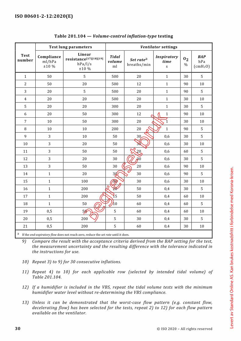
ISO 80601-2-12:2020(E)
30 © ISO 2020 – All rights reserved
Table 201.104 — Volume-control inflation-type testing
Test number
Test lung parameters Ventilator settings
Compliance ml/hPa ±10 %
Linear resistance[17][18][19]
hPa/l/s ±10 %
Tidal volume
ml Set ratea
breaths/min
Inspiratory time
s
O2 %
BAP hPa
(cmH2O)
1 50 5 500 20 1 30 5
2 50 20 500 12 1 90 10
3 20 5 500 20 1 90 5
4 20 20 500 20 1 30 10
5 20 20 300 20 1 30 5
6 20 50 300 12 1 90 10
7 10 50 300 20 1 30 10
8 10 10 200 20 1 90 5
9 3 10 50 30 0,6 30 5
10 3 20 50 30 0,6 30 10
11 3 50 50 20 0,6 60 5
12 3 20 30 30 0,6 30 5
13 3 50 30 20 0,6 90 10
14 1 20 30 30 0,6 90 5
15 1 100 30 30 0,6 30 10
16 1 200 20 50 0,4 30 5
17 1 200 15 50 0,4 60 10
18 1 50 10 60 0,4 60 5
19 0,5 50 5 60 0,4 60 10
20 0,5 200 5 30 0,4 30 5
21 0,5 200 5 60 0,4 30 10
a If the end-expiratory flow does not reach zero, reduce the set rate until it does.
9) Compare the result with the acceptance criteria derived from the BAP setting for the test, the measurement uncertainty and the resulting difference with the tolerance indicated in the instructions for use.
10) Repeat 3) to 9) for 30 consecutive inflations.
11) Repeat 4) to 10) for each applicable row (selected by intended tidal volume) of Table 201.104.
12) If a humidifier is included in the VBS, repeat the tidal volume tests with the minimum humidifier water level without re-determining the VBS compliance.
13) Unless it can be demonstrated that the worst-case flow pattern (e.g. constant flow, decelerating flow) has been selected for the tests, repeat 2) to 12) for each flow pattern available on the ventilator.
Begre
nset
bru
k
Leve
rt a
v St
anda
rd O
nlin
e A
S. K
an b
ruke
s ko
stna
dsfr
itt i
forb
inde
lse
med
Kor
ona-
kris
en.

ISO 80601-2-12:2020(E)
© ISO 2020 – All rights reserved 31
14) If the ventilator permits operation without compliance correction, repeat 2) to 10) without compliance correction.
g) O2 error
The accuracy of the inspiratory O2 concentration of the gas delivered is assessed by placing the sensor of an O2 concentration measuring device at the patient-connection port or inside the test lung. If the sensor is located at the patient-connection port, the value of the concentration is the flow-weighted average concentration during the inflation phase.
1) Evaluate the measured O2 concentration with the acceptance criteria derived from the O2 setting for the test and the measurement uncertainty. Compare the resulting difference with the tolerance indicated in the instructions for use. If the sensor is located inside the test lung, care should be taken to allow sufficient time for the gas mixture in the test lung to reach a stable concentration. If the sensor is located in the tubing system, care should be taken to ensure that the measuring device has a sufficiently fast response to permit determination of the flow-weighted average concentration during the inflation phase.
2) If the O2 concentration measuring device has pressure dependencies, compensate for these dependencies.
3) Compare each result with the acceptance criteria derived from the O2 setting for the test in f), above, the measurement uncertainty and the tolerance indicated in the instructions for use.
201.12.1.102 * Pressure-control inflation-type a) With a pressure-control inflation-type selected and the ventilator operating in normal
condition, the accuracy as determined for the test settings and conditions specified in this document shall be disclosed in the instructions for use, as the maximum bias error and maximum linearity error.
EXAMPLE ±(3,0 +(5 % of the set pressure)) hPa; (±(3,0 +(5 % of the set pressure)) cmH2O)
b) This disclosure shall include at least:
1) the maximum error of the airway pressure (Paw) at the end of the inflation phase in relation to the set value;
2) the maximum error of PEEP in relation to the set value BAP; and
3) * the maximum error of the inspiratory oxygen (O2) concentration at the patient-connection port in relation to the set value.
4) the disclosed accuracies shall include the effects of the range of the rated input oxygen concentration.
c) All of the errors may be reported separately for the following ranges of intended tidal volume:
1) Vtidal ≥ 300 ml;
2) 300 ml ≥ Vtidal ≥ 50 ml; and
3) Vtidal ≤ 50 ml.
Begre
nset
bru
k
Leve
rt a
v St
anda
rd O
nlin
e A
S. K
an b
ruke
s ko
stna
dsfr
itt i
forb
inde
lse
med
Kor
ona-
kris
en.

ISO 80601-2-12:2020(E)
32 © ISO 2020 – All rights reserved
d) The accuracy of the performance of the ventilator shall either be:
1) determined for each VBS configuration indicated in the instructions for use; or
2) determined for the worst-case VBS configuration indicated in the instructions for use.
NOTE 1 The worst-case VBS configuration can be different for each error or each nominal tidal volume range.
In determining the worst-case configuration consider use with active and passive humidification.
e) If worst-case VBS configurations are used, the rationale for their selection shall be documented in the risk management file.
Check conformity by inspection of the risk management file for the rationale, if applicable, and with the following tests:
NOTE 2 In some cases, the following tests can be carried out simultaneously.
f) End-inspiratory and end-expiratory pressure errors
1) Set up the ventilator as shown in Figure 201.102.
2) If applicable, determine or input the VBS compliance required for compliance correction as indicated in the instructions for use and activate this correction. If a humidifier is used, fill the humidifier to the maximum water level prior to determining the VBS compliance.
3) Utilize the test parameters and settings of the first applicable row (selected by typical intended tidal volume) of Table 201.105. Wait until steady-state conditions are achieved.
4) Determine the airway pressure at the end of the inflation phase as the average over the preceding 50 ms.
5) Compare the result with the acceptance criteria derived from the pressure setting for the test, the measurement uncertainty and the resulting difference with the tolerance indicated in the instructions for use.
6) Determine the tidal volume, for example via integration of the flow signal provided by a calibrated flow sensor located at the patient-connection port, or by the product of the test lung compliance and the measured change of lung pressure, compensated for temperature effects due to fast compression of the gas, if necessary.
NOTE 3 Additional information on the construction of an isothermal test lung is found in Reference [23].
7) If the ventilator is equipped with tidal volume monitoring equipment, determine the accuracy of the tidal volume monitoring equipment by comparing its reading adjusted for the measurement uncertainty to the tidal volume determined in 6). Refer to Table 201.104.
8) Determine the PEEP as the average of the airway pressure measurements over the last 50 ms of the expiratory phase.
9) Compare the result with the acceptance criteria derived from the BAP setting for the test, the measurement uncertainty and the resulting difference with the tolerance indicated in the instructions for use.
Begre
nset
bru
k
Leve
rt a
v St
anda
rd O
nlin
e A
S. K
an b
ruke
s ko
stna
dsfr
itt i
forb
inde
lse
med
Kor
ona-
kris
en.

ISO 80601-2-12:2020(E)
© ISO 2020 – All rights reserved 33
10) Repeat 2) to 9) for 30 consecutive inflations.
11) Repeat 2) to 10) for each applicable row (selected by intended tidal volume) of Table 201.105.
12) If a humidifier is included in the VBS, repeat the airway pressure tests with the minimum humidifier water level without re-determining the VBS compliance.
13) If the ventilator permits operation without compliance correction, repeat 2) to 12) without compliance correction.
g) O2 error
The accuracy of the inspiratory O2 concentration of the gas delivered is assessed by placing the sensor of an O2 concentration measuring device at the patient-connection port or inside the test lung. If the sensor is located at the patient-connection port, the value of the concentration is the flow-weighted average concentration as a function of flow during the inflation phase.
1) Evaluate the measured O2 concentration with the acceptance criteria derived from the O2 setting for the test, the measurement uncertainty. Compare the resulting difference with the tolerance indicated in the instructions for use. If the sensor is located inside the test lung, care should be taken to allow sufficient time for the gas mixture in the test lung to reach a stable concentration. If the sensor is located in the tubing system, care should be taken to ensure that the measuring device has a sufficiently fast response to permit determination of the flow-weighted average concentration during the inflation phase.
If the O2 concentration measuring device has pressure dependencies, compensate for these dependencies.
2) Compare each result with the acceptance criteria derived from the O2 setting for the test in f), above, the measurement uncertainty and the tolerance indicated in the instructions for use.
Begre
nset
bru
k
Leve
rt a
v St
anda
rd O
nlin
e A
S. K
an b
ruke
s ko
stna
dsfr
itt i
forb
inde
lse
med
Kor
ona-
kris
en.

ISO 80601-2-12:2020(E)
34 © ISO 2020 – All rights reserved
Table 201.105 — Pressure-control inflation-type testing
Test number
Intended tidal
volumea
Test lung parameters Ventilator settings
Compliance Linear
Resistance [17][18][19]
Set rateb Inspiratory
timec
Δ inspiratory pressured
O2 % BAP
ml ml/hPa ±10 %
hPa/l/s ±10 % breaths/min s hPa hPa
(cmH2O)
1 500 50 5 20 1 10 30 5
2 500 50 20 12 1 15 90 10
3 500 20 5 20 1 25 90 5
4 500 20 20 20 1 25 30 10
5 300 20 20 20 1 15 30 5
6 300 20 50 12 1 25 90 10
7 300 10 50 20 1 30 90 5
8 200 10 10 20 1 25 30 10
9 50 3 10 30 0,6 15 30 5
10 50 3 20 30 0,6 15 30 10
11 50 3 50 20 0,6 25 60 5
12 30 3 20 30 0,6 10 30 5
13 30 3 50 20 0,6 15 90 10
14 30 1 20 30 0,6 30 90 5
15 30 1 100 30 0,6 30 30 10
16 20 1 200 50 0,4 20 30 5
17 15 1 200 50 0,4 15 60 10
18 10 1 50 60 0,4 10 60 5
19 5 0,5 50 60 0,4 15 60 10
20 5 0,5 50 30 0,4 10 30 5
21 5 0,5 200 60 0,4 15 30 10
a The volume in this column is intended to be used for the selection of the test conditions and parameters based on the intended tidal volume of the ventilator.
b If the end-expiratory flow does not reach zero, reduce the set rate until it does.
c The rise time of the ventilator should be set to a value that ensures that the set pressure can be reached within the inspiratory time.
d For the purposes of this test, the set pressure is relative to set BAP.
201.12.1.103 Other inflation-types a) If other inflation-types are provided, then with each other inflation-type selected and the
ventilator operating in normal condition,
1) the performance at the patient-connection port; and
2) their acceptance criteria;
as determined by the manufacturer, shall be disclosed in the instructions for use.
Begre
nset
bru
k
Leve
rt a
v St
anda
rd O
nlin
e A
S. K
an b
ruke
s ko
stna
dsfr
itt i
forb
inde
lse
med
Kor
ona-
kris
en.

ISO 80601-2-12:2020(E)
© ISO 2020 – All rights reserved 35
3) The disclosed performance and acceptance criteria shall include the effects of the range of the rated input oxygen concentration.
b) All of the performance and acceptance criteria may be reported separately for the following ranges of intended tidal volume:
1) Vtidal ≥ 300 ml;
2) 300 ml ≥ Vtidal ≥ 50 ml; and.
3) Vtidal ≤ 50 ml.
c) The acceptance criteria of the performance of the ventilator shall either be:
1) determined for each VBS configuration indicated in the instructions for use; or
2) determined for the worst-case VBS configuration indicated in the instructions for use.
NOTE The worst-case VBS configuration can be different for each error or each nominal tidal volume range.
In determining the worst-case configuration consider use with active and passive humidification.
d) If worst-case VBS configurations are used, the rationale for their selection shall be documented in the risk management file.
Check conformity by inspection of the instructions for use, inspection of the risk management file for the rationale, if applicable, and with the tests specified by the manufacturer.
201.12.1.104 * Inspiratory volume monitoring a) If the ventilator is equipped with inspiratory volume monitoring equipment, the accuracy of
the inspiratory volume monitoring equipment shall be disclosed in the instructions for use.
b) For actual tidal volumes greater than 50 ml, the accuracy of the inspiratory volume monitoring equipment shall be within ±(4,0 +(15 % of the actual inspiratory volume)) ml.
Check conformity with the following.
Confirm that the inspiratory volume monitoring equipment accuracy as measured in 201.12.1.101 7) 7) and 201.12.1.102 f) 7) is within the accuracy disclosed in the instructions for use. For tidal volumes greater than 50 ml ensure that the accuracy disclosed in the instructions for use is ±(4,0 +(15 % of the actual inspiratory volume)) ml or better.
201.12.1.105 * Response of the ventilator to an increase in set O2 concentration
a) The length of time required for the oxygen concentration in the tidal volume to change from a volume fraction of oxygen of 21 % to a volume fraction of 90 % of the maximum achievable volume fraction of oxygen shall be disclosed in the instructions for use.
b) The worst-case input oxygen concentration within the rated range shall be utilized for this test.
c) The time shall be reported separately, as appropriate, at tidal volumes for each intended tidal volume under the conditions of Table 201.106, using:
Begre
nset
bru
k
Leve
rt a
v St
anda
rd O
nlin
e A
S. K
an b
ruke
s ko
stna
dsfr
itt i
forb
inde
lse
med
Kor
ona-
kris
en.

ISO 80601-2-12:2020(E)
36 © ISO 2020 – All rights reserved
1) the worst-case VBS; or
2) the maximum internal volume VBS and
3) if base or continuous flow controls are provided, at:
i) the minimum bias flow, or ii) the minimum continuous flow.
d) The time may be reported separately for:
1) each VBS; or
2) as a maximum (for the worst-case VBS and minimum tidal volume).
Check conformity with the following tests:
e) Set up the ventilator as shown in Figure 201.103 using the worst-case VBS or using the maximum internal volume VBS. If the VBS includes a humidifier, use the minimum humidifier water level indicated in the instructions for use.
f) Utilize the test conditions for the first applicable column available on the ventilator (selected by intended tidal volume range) in Table 201.106.
Key
1 ventilator under test 5 data acquisition system 2 pressure sensor 6 resistance 3 flow sensor 7 test lung 4 oxygen sensor
Begre
nset
bru
k
Leve
rt a
v St
anda
rd O
nlin
e A
S. K
an b
ruke
s ko
stna
dsfr
itt i
forb
inde
lse
med
Kor
ona-
kris
en.

ISO 80601-2-12:2020(E)
© ISO 2020 – All rights reserved 37
Figure 201.103 — O2 concentration change test setup
Table 201.106 — Test conditions for O2 concentration change tests
Adjustable parameter
Test condition
For a ventilator intended to provide tidal volume
Vtidal ≥ 300 ml 300 ml ≥ Vtidal ≥ 50 ml Vtidal ≤ 50 ml
Tidal volume, Vtidala 500 ml 150 ml 30 ml
Set rate 10 min−1 20 min−1 30 min−1
I:E ratio 1:2 1:2 1:2
Resistance, Rb[17][18][19] 5 hPa(l/s) −1 ± 10 % 20 hPa(l/s) −1 ± 10 % 50 hPa(l/s) −1 ± 10 %
a Vtidal is determined by using the settings of the ventilator.
b The accuracy for R applies over the ranges of the measured parameters.
g) Ventilate the test lung with a set oxygen concentration of 21 % volume fraction.
h) Wait until equilibrium is reached in the inspired oxygen concentration at the patient-connection port.
i) Change the set oxygen concentration to the maximum volume fraction that the ventilator permits.
j) Measure the time delay between setting the new concentration and achieving 90 % of the final oxygen concentration during inspiration at the patient-connection port. If the sensor is located inside the test lung, care should be taken to allow sufficient time for the gas mixture in the test lung to reach a stable concentration. If the sensor is located in the tubing system, care should be taken to ensure that the measuring device has a sufficiently fast response to permit determination of the flow-weighted average concentration during the inflation phase.
k) Ensure that the measured time delay is less than or equal to that indicated in the instructions for use.
l) Repeat g) to k) for each applicable column (selected by intended tidal volume range) in Table 201.106.
m) If the ventilator is provided with bias flow during the expiratory phase, repeat g) to l) at the minimum bias flow setting available on the ventilator.
n) If the ventilator is provided with continuous flow throughout the respiratory cycle, repeat g) to l) at the minimum continuous flowrate setting available on the ventilator.
201.12.4 Protection against hazardous output
Addition:
201.12.4.101 Oxygen monitor a) The ventilator shall either
Begre
nset
bru
k
Leve
rt a
v St
anda
rd O
nlin
e A
S. K
an b
ruke
s ko
stna
dsfr
itt i
forb
inde
lse
med
Kor
ona-
kris
en.

ISO 80601-2-12:2020(E)
38 © ISO 2020 – All rights reserved
1) be equipped with O2 monitoring equipment for the measurement of the inspiratory oxygen concentration (e.g. in the inspiratory limb or at the patient-connection port) that is integral to the ventilator; or
2) the instructions for use shall contain a statement to the effect that the ventilator is to be equipped with O2 monitoring equipment for measurement of the inspiratory oxygen concentration (e.g. in the inspiratory limb or at the patient-connection port) before being put into service.
b) Such O2 monitoring equipment shall conform with the following subclauses of ISO 80601-2-55:2018:
1) 201.7.4.3;
2) 201.7.9.2.9.101 k);
3) 201.12.1.101;
4) 201.12.1.102;
5) 201.12.1.103; and
6) 208.6.1.2.
c) Where the O2 monitoring equipment is not an integral part of the ventilator, the instructions for use shall include the following:
1) a statement to the effect that the ventilator is to be provided with O2 monitoring equipment that conforms with ISO 80601-2-55:2018 before being put into service; and
2) information on where to connect the O2 monitoring equipment.
d) The O2 monitoring equipment shall, in addition, be equipped with an alarm system that includes a high oxygen level alarm condition.
e) The high oxygen level alarm condition:
1) shall be at least medium priority; unless
2) an intelligent alarm system, based on additional information, determines that the high oxygen level alarm condition is suppressed or its priority is changed.
NOTE A low oxygen level alarm condition is required by ISO 80601-2-55.
Check conformity by inspection of the instructions for use or application of the tests of ISO 80601-2-55:2018.
201.12.4.102 * Measurement of airway pressure a) The ventilator shall be equipped with monitoring equipment to measure the airway pressure.
b) The site of actual measurement:
1) may be anywhere in the ventilator breathing system; but
Begre
nset
bru
k
Leve
rt a
v St
anda
rd O
nlin
e A
S. K
an b
ruke
s ko
stna
dsfr
itt i
forb
inde
lse
med
Kor
ona-
kris
en.

ISO 80601-2-12:2020(E)
© ISO 2020 – All rights reserved 39
2) the indicated value shall be referenced to the patient-connection port.
c) Under steady-state conditions, the indicated airway pressure shall be accurate to within ±(2 +(4 % of the actual reading)) hPa (±(2 +(4 % of the actual reading)) cmH2O).
Check conformity by functional testing.
201.12.4.103 * Measurement of expired volume and low volume alarm conditions
201.12.4.103.1 Ventilators intended to provide a tidal volume >50 ml a) A ventilator intended to provide a tidal volume greater than 50 ml shall either:
1) be equipped with monitoring equipment for indicating the volume expired through the patient-connection port; or
2) if not so equipped, the instructions for use shall include a statement to the effect that the ventilator is to be equipped with monitoring equipment that conforms with this document before being put into service.
If equipped,
b) unless the expired volume monitoring equipment is an integral part of the ventilator, information on where to connect the expired volume monitoring equipment shall be disclosed in the instructions for use.
c) the accuracy of measurement of expired volumes greater than 50 ml shall be within ±(4,0 +(15 % of the actual volume expired through the patient-connection port)) ml.
d) the accuracy of expired volume monitoring equipment shall be disclosed in the instructions for use.
e) The disclosed accuracies shall include the effects of the range of the rated input oxygen concentration.
NOTE The use of Oxygen 93 % can reduce the accuracy of measurement due to influence of other gases such as argon on flow measurement.
f) the expired volume monitoring equipment shall be equipped with an alarm system to indicate when:
1) the low expired volume alarm limit is reached; and
2) the high expired volume alarm limit is reached.
g) the low expired volume and the high expired volume alarm conditions:
1) shall be at least medium priority; unless
2) an intelligent alarm system, based on additional information, determines that
i) the low expired volume or ii) the high expired volume alarm condition
Begre
nset
bru
k
Leve
rt a
v St
anda
rd O
nlin
e A
S. K
an b
ruke
s ko
stna
dsfr
itt i
forb
inde
lse
med
Kor
ona-
kris
en.
ISO 80601-2-12:2020(E)
40 © ISO 2020 – All rights reserved
is suppressed or its priority is changed.
h) the expired volume monitoring equipment may be equipped with an alarm system that:
1) starts with low priority alarm conditions to indicate when the expired volume reaches either alarm limit; and
2) if this state continues, escalates to medium priority alarm conditions.
i) the expired volume alarm limits may be:
1) pre-adjusted;
2) responsible organization-adjustable;
3) healthcare professional operator-adjustable;
4) ventilator-adjustable; or
5) a combination of healthcare professional operator-adjustable and ventilator-adjustable.
j) if the alarm limits are adjustable by the ventilator, a summary description of the algorithm that determines the alarm limit values shall be disclosed in the instructions for use.
NOTE Depending on the type of ventilation-mode being utilized, there can be more than one active alarm limit.
Check conformity by functional testing using the test conditions described in Table 201.104 and Table 201.105 selecting the appropriate rows based on intended tidal volume and inspection of the instructions for use. Select and set up the worst-case VBS configuration indicated in the instructions for use.
EXAMPLE Minimum or maximum VBS compliance.
For testing with a humidifier, repeat the tests at the minimum and maximum water levels (2 sets of tests for a humidifier).
201.12.4.103.2 Ventilators intended to provide a tidal volume ≤50 ml a) If a ventilator is intended to provide a tidal volume ≤50 ml, it may be equipped with expired
volume monitoring equipment.
b) The accuracy of the expired volume monitoring equipment at an expired volume ≤50 ml shall be disclosed in the instructions for use.
c) The disclosed accuracies shall include the effects of the range of the rated input oxygen concentration.
NOTE 1 The use of Oxygen 93 % can reduce the accuracy of measurement due to influence of other gases such as argon on flow measurement.
d) The expired volume monitoring equipment may be equipped with an alarm system to indicate when the expired volume reaches the low expired volume alarm limit.
e) The low expired volume alarm condition:
Begre
nset
bru
k
Leve
rt a
v St
anda
rd O
nlin
e A
S. K
an b
ruke
s ko
stna
dsfr
itt i
forb
inde
lse
med
Kor
ona-
kris
en.

ISO 80601-2-12:2020(E)
© ISO 2020 – All rights reserved 41
1) shall be at least low priority; unless
2) an intelligent alarm system, based on additional information, determines that:
i) the low expired volume alarm condition is suppressed; or ii) its priority is changed.
f) If provided, the expired volume alarm limit may be:
1) pre-adjusted;
2) responsible organization-adjustable;
3) healthcare professional operator-adjustable;
4) ventilator-adjustable; or
5) a combination of healthcare professional operator-adjustable and ventilator-adjustable.
g) If the alarm limit is adjustable by the ventilator, a summary description of the algorithm that determines the alarm limit values shall be disclosed in the instructions for use.
NOTE 2 Depending on the type of ventilation-mode being utilized, there can be more than one active alarm limit.
Check conformity by functional testing using the test conditions described in Table 201.104 and Table 201.105 selecting the appropriate rows based on intended tidal volume and inspection of the instructions for use. Select and set up the worst-case VBS configuration indicated in the instructions for use.
EXAMPLE Minimum and maximum VBS compliance.
For testing with a humidifier, repeat the tests at minimum and maximum water levels (2 sets of tests for a humidifier).
201.12.4.104 * Expiratory end-tidal CO2 monitoring equipment a) If a ventilator intended to provide a tidal volume ≤50 ml is not equipped with expired volume
monitoring equipment (see 201.12.4.103.2), the ventilator shall either:
1) be equipped with CO2 monitoring equipment for the measurement of the expiratory carbon dioxide concentration (e.g. in the expiratory limb or at the patient-connection port) that is integral to the ventilator; or
2) the instructions for use shall contain a statement to the effect that the ventilator is to be equipped with CO2 monitoring equipment for the measurement of the expiratory carbon dioxide concentration (e.g. in the expiratory limb or at the patient-connection port) before being put into service.
b) Such CO2 monitoring equipment shall conform with the following subclauses of ISO 80601-2-55:2018:
1) 201.7.4.3;
2) 201.7.9.2.9.101 k);
Begre
nset
bru
k
Leve
rt a
v St
anda
rd O
nlin
e A
S. K
an b
ruke
s ko
stna
dsfr
itt i
forb
inde
lse
med
Kor
ona-
kris
en.

ISO 80601-2-12:2020(E)
42 © ISO 2020 – All rights reserved
3) 201.12.1.101;
4) 201.12.1.102;
5) 201.12.1.103; and
6) for expired CO2 concentration, 208.6.1.2.
c) Where the CO2 monitoring equipment is not an integral part of the ventilator, the instructions for use shall include the following:
1) a statement to the effect that the ventilator is to be provided with CO2 monitoring equipment that conforms with ISO 80601-2-55:2018 before being put into service; and
2) information on where to connect the CO2 monitoring equipment.
Check conformity by inspection.
201.12.4.105 * Maximum limited pressure protection device a) A protection device shall be provided to prevent the airway pressure from exceeding the
maximum limited pressure under both:
1) normal condition; and
2) single fault condition.
b) The maximum limited pressure shall not exceed the lower of:
1) 20 hPa (20 cmH2O) more than the high pressure alarm limit; or
2) 125 hPa (125 cmH2O).
NOTE See also 201.12.4.106 and 201.12.4.110.
Check conformity by functional testing.
201.12.4.106 * High airway pressure alarm condition and protection device a) The ventilator shall be equipped with monitoring equipment with an alarm system to indicate
when the high-pressure limit for airway pressure is reached.
b) The high airway pressure alarm condition:
1) shall be high priority; unless
2) an intelligent alarm system, based on additional information, determines that:
i) the high airway pressure alarm condition is suppressed; or ii) its priority is changed.
c) The high airway pressure alarm limit may be:
1) independently adjustable; or
Begre
nset
bru
k
Leve
rt a
v St
anda
rd O
nlin
e A
S. K
an b
ruke
s ko
stna
dsfr
itt i
forb
inde
lse
med
Kor
ona-
kris
en.
ISO 80601-2-12:2020(E)
© ISO 2020 – All rights reserved 43
2) related to the set pressure of the ventilator.
d) It shall not be possible to set the high-airway pressure alarm limit to a value greater than the maximum limited pressure limit.
e) * Means shall be provided to require the operator to perform a deliberate sequence of actions to confirm the setting of the high-pressure alarm limit to values exceeding the lower of:
1) 20 hPa (20 cmH2O) more than the operator-set pressure; or
NOTE The operator-set pressure does not apply when by design the ventilator adjusts the airway pressure on a breath-by-breath basis.
2) 60 hPa (60 cmH2O).
f) * Patient-generated transient pressure increases should not cause the high-pressure alarm condition.
EXAMPLE A transient pressure increase caused by the patient coughing.
g) The high airway pressure alarm condition delay shall not exceed 200 ms and the ventilator shall:
1) act to attempt to cause the pressure to start to decline within that duration; and
2) act to prevent the pressure from continuing to rise.
h) * Whenever the high-pressure alarm condition occurs, the ventilator shall, within no more than two respiratory cycles or 15 s, whichever is less, reduce the airway pressure to either:
1) the atmospheric pressure; or
2) the set BAP level.
i) During single fault condition, the airway pressure may fall below the set BAP level.
Check conformity by functional testing.
201.12.4.107 PEEP alarm conditions a) The ventilator shall be equipped with monitoring equipment with an alarm system that detects
an alarm condition to indicate when the end-expiratory pressure is above the high PEEP alarm limit.
b) The ventilator may be equipped with monitoring equipment with an alarm system that detects an alarm condition to indicate when the end-expiratory pressure is below the low PEEP alarm limit.
c) Both the high and low PEEP alarm conditions:
1) shall be of at least medium priority; unless
2) an intelligent alarm system, based on additional information determines that the high or low PEEP alarm condition:
Begre
nset
bru
k
Leve
rt a
v St
anda
rd O
nlin
e A
S. K
an b
ruke
s ko
stna
dsfr
itt i
forb
inde
lse
med
Kor
ona-
kris
en.

ISO 80601-2-12:2020(E)
44 © ISO 2020 – All rights reserved
i) is suppressed; or ii) the priority is changed.
d) The alarm condition delay for high PEEP alarm condition shall not exceed the duration of three inflations.
Check conformity by functional testing with every VBS indicated in the instructions for use.
NOTE To perform this test, modification of the ventilator to disable the BAP control can be required.
201.12.4.108 * Obstruction alarm condition a) The ventilator shall be equipped with monitoring equipment with an alarm system that detects
a technical alarm condition to indicate when the alarm limit for obstruction is reached.
EXAMPLE Alarm condition to warn of: — an obstructed inspiratory or expiratory breathing tube; — a blocked exhalation valve; or — a blocked expiratory breathing system filter.
b) The obstruction technical alarm condition:
1) shall be high priority, unless
2) an intelligent alarm system, based on additional information, determines that the obstruction technical alarm condition:
i) is suppressed; or ii) its priority is changed.
c) The alarm condition delay shall not exceed more than
1) two respiratory cycles or
2) 5 s,
whichever is greater.
d) Whenever the obstruction alarm condition occurs, the ventilator shall, within no more than one respiratory cycle, reduce the airway pressure to either:
1) atmospheric pressure; or
2) the set BAP level.
e) The ventilator should be equipped with a protection device to allow spontaneous breathing when obstruction occurs.
f) If equipped with the protection device, the pressure drop measured at the patient-connection port, with all recommended accessories in place, shall not exceed 6,0 hPa (6,0 cmH2O) at a flowrate of:
1) 30 l/min for a ventilator intended to provide tidal volume, Vtidal ≥ 300 ml;
2) 15 l/min for a ventilator intended to provide tidal volume, 300 ml ≥ Vtidal ≥ 50 ml; and
Begre
nset
bru
k
Leve
rt a
v St
anda
rd O
nlin
e A
S. K
an b
ruke
s ko
stna
dsfr
itt i
forb
inde
lse
med
Kor
ona-
kris
en.

ISO 80601-2-12:2020(E)
© ISO 2020 – All rights reserved 45
3) 2,5 l/min for a ventilator intended to provide tidal volume, Vtidal ≤ 50 ml.
g) The accompanying document shall describe:
1) the means by which the obstruction alarm condition is determined; and
2) a means to test the obstruction alarm condition.
Check conformity by functional testing with each VBS indicated in the instructions for use, according to the test method described in the accompanying document.
201.12.4.109 * Disconnection alarm condition a) The ventilator shall be equipped with an alarm system that detects a technical alarm condition
to indicate when conditions in the VBS reach the alarm limit for disconnection.
NOTE Disconnection can be detected using one or more means, for example measurement of pressure at the ventilator gas output port, measurement of flow at the exhalation valve or measurement of expired flow or end-tidal CO2 at the patient-connection port.
b) The disconnection technical alarm condition shall be at least medium priority.
c) The alarm off or audio off of the disconnection technical alarm condition alarm signals shall not be provided when the ventilator is operating in any ventilator-operational mode intended for a ventilator-dependent patient.
d) The alarm off or audio off of the disconnection technical alarm condition alarm signals may be provided when the ventilator is operating in any ventilator-operational mode not intended for a ventilator-dependent patient.
e) The instructions for use shall disclose the maximum alarm condition delay of the disconnection technical alarm condition.
f) The instructions for use shall disclose any use scenarios in which decannulation might not be detected as a VBS disconnection.
EXAMPLE For a neonatal ventilator normally intended to be used with a flow sensor placed between the patient-connection port and the tracheal tube, use of the ventilator with the flow sensor disconnected.
Check conformity by functional testing and inspection of the instructions for use.
201.12.4.110 Protection against inadvertent setting of high airway pressure
Means shall be provided to require the operator to perform a deliberate sequence of actions to confirm any airway pressure settings exceeding 60 hPa (60 cmH2O). See also 201.12.4.105 b) and 206.101 a) 7).
Check conformity by functional testing.
201.12.101 * Protection against accidental or unintentional adjustments a) The ventilator shall include a means for the healthcare professional operator to confirm the
ventilation-mode and settings:
Begre
nset
bru
k
Leve
rt a
v St
anda
rd O
nlin
e A
S. K
an b
ruke
s ko
stna
dsfr
itt i
forb
inde
lse
med
Kor
ona-
kris
en.

ISO 80601-2-12:2020(E)
46 © ISO 2020 – All rights reserved
1) during the start-up procedure; and
2) when the ventilation-mode is changed during use.
b) Means of protection shall be provided against accidental or unintentional adjustment of controls that can create a hazardous situation, including against accidently turning the ventilator off.
c) The usability of these means of protection shall be evaluated in the usability engineering process.
NOTE The requirements for the usability engineering process are found in IEC 60601-1:2005+AMD1:2012, 12.2 and IEC 60601-1-6:2010+AMD1:2013.
Check conformity by functional testing and inspection of usability engineering file.
201.13 Hazardous situations and fault conditions for ME equipment
Clause 13 of the general standard applies, except as follows:
Addition:
201.13.2.101 * Additional specific single fault conditions
A ventilator shall be so designed and constructed that the following single fault conditions shall not cause an unacceptable risk:
a) * disruption of the gas delivery to the patient-connection port from the ventilator;
b) * when present, disruption of the gas flow pathway from the patient-connection port to the ventilator;
c) * removal or failure of a healthcare professional operator-detachable breathing system filter; and
d) * disruption of a functional connection between parts of the ventilator or ME system.
EXAMPLE 1 Loss of communication between the ventilator and its remote (wired or wireless) control or monitoring module.
EXAMPLE 2 Loss of communication between the ventilator and its distributed alarm system.
Check conformity by functional testing and inspection of risk management file.
201.13.2.102 * Failure of one gas supply to a ventilator a) Following the failure of one gas supply connected to a high-pressure input port, a ventilator
shall maintain normal use.
b) The ventilator shall be equipped with an alarm system that detects a technical alarm condition to indicate this gas supply failure.
c) The gas supply failure technical alarm condition:
Begre
nset
bru
k
Leve
rt a
v St
anda
rd O
nlin
e A
S. K
an b
ruke
s ko
stna
dsfr
itt i
forb
inde
lse
med
Kor
ona-
kris
en.

ISO 80601-2-12:2020(E)
© ISO 2020 – All rights reserved 47
1) shall be at least low priority; unless
2) an intelligent alarm system, based on additional information, determines that the gas supply failure technical alarm condition is suppressed.
Check conformity by functional testing.
201.13.2.103 * Independence of ventilation control function and related risk control measures
a) A single fault condition shall not cause the simultaneous failure of:
1) a ventilation control function; and
2) the corresponding protection device.
b) A single fault condition shall not cause either:
1) a ventilation control function and the corresponding monitoring equipment; or
2) a ventilation control function and the corresponding alarm system
to fail in such a way that the loss of the ventilation control function is not detected.
Check conformity by inspection and functional testing.
201.13.2.104 * Failure of functional connection to a ventilator control or monitoring means
a) Following the failure of a functional connection to a ventilator control or monitoring means, the ventilator shall continue to ventilate the patient.
b) The ventilator shall be equipped with an alarm system that detects a technical alarm condition to indicate this communication failure.
c) The communication failure technical alarm condition:
1) shall be at least medium priority; unless
2) an intelligent alarm system, based on additional information, determines that the communication failure technical alarm condition:
i) is suppressed; or ii) the priority is changed.
Check conformity by functional testing.
201.14 Programmable electrical medical systems (PEMS)
Clause 14 of the general standard applies, except as follows:
Addition:
Begre
nset
bru
k
Leve
rt a
v St
anda
rd O
nlin
e A
S. K
an b
ruke
s ko
stna
dsfr
itt i
forb
inde
lse
med
Kor
ona-
kris
en.
ISO 80601-2-12:2020(E)
48 © ISO 2020 – All rights reserved
201.14.101 Software life cycle a) The programmable electronic subsystems (PESS) of a ventilator shall be developed with a
design process conforming with IEC 62304:2006+AMD1:2015.
b) The ventilation control software items of the ventilator PESS without an independent risk control measure external to the PESS shall be considered as software safety Class C.
Check conformity by inspection of the documentation required by IEC 62304:2006+AMD1:2015 for the software safety class (the requirements are found in 1.4 of IEC 62304:2006+AMD1:2015).
201.15 Construction of ME equipment
Clause 15 of the general standard applies, except as follows:
Addition:
201.15.3.5.101 Additional requirements for rough handling
201.15.3.5.101.1 * Shock and vibration (robustness) a) A ventilator and its parts, including applicable accessories shall have adequate mechanical
strength when subjected to mechanical stress caused by normal use, pushing, impact, dropping and rough handling.
b) Stationary ME equipment is exempt from the requirements of this subclause.
c) After the following tests, the ventilator shall:
1) maintain basic safety and essential performance; and
2) conform with the requirements of 201.12.1 and 201.12.4.
NOTE 1 A ventilator tested and conforming with a more severe requirement is considered to conform with the corresponding requirement of this subclause.
Conformity is checked by performing the following tests:
d) Shock test in conformance with IEC 60068-2-27:2008, using the following conditions:
NOTE 2 This represents IEC/TR 60721-4-7:2001[24], Class 7M2.
1) test type: Type 1:
peak acceleration: 150 m/s2 (15 g);
duration: 11 ms;
pulse shape: half-sine; and
number of shocks: 3 shocks per direction per axis (18 total);
or
Begre
nset
bru
k
Leve
rt a
v St
anda
rd O
nlin
e A
S. K
an b
ruke
s ko
stna
dsfr
itt i
forb
inde
lse
med
Kor
ona-
kris
en.

ISO 80601-2-12:2020(E)
© ISO 2020 – All rights reserved 49
2) test type: Type 2:
peak acceleration: 300 m/s2 (30 g);
duration: 6 ms;
pulse shape: half-sine; and
number of shocks: 3 shocks per direction per axis (18 total).
e) Broadband random vibration test in conformance with IEC 60068-2-64:2008, using the following conditions:
NOTE 3 This represents IEC/TR 60721-4-7:2001[24], Classes 7M1 and 7M2, modified.
1) acceleration amplitude:
10 Hz to 100 Hz: 1,0 (m/s2)2/Hz; and
100 Hz to 500 Hz: −6 db per octave;
2) duration: 10 min per perpendicular axis (3 total).
f) Confirm that basic safety and essential performance and the requirements of 201.12.1 and 201.12.4 are maintained following the tests.
201.15.3.5.101.2 * Shock and vibration for a transit-operable ventilator during operation
a) A ventilator and its parts, including applicable accessories, intended for transit-operable use (during patient transport inside a healthcare facility) shall have adequate mechanical strength when subjected to mechanical stress caused by normal use, pushing, impact, dropping and rough handling while operating.
b) For this test, the ventilator and its parts, and applicable accessories, shall be mounted using the mounting accessories indicated in the accompanying documents.
If more than one mounting system is described in the accompanying documents, multiple tests are required.
NOTE A ventilator tested and conforming with a more severe requirement is considered to conform with the corresponding requirement of this subclause.
c) During the following test, a ventilator shall maintain basic safety and essential performance while ventilating a test lung using the worst-case conditions and parameters of Table 201.102, selected by intended tidal volume, as appropriate.
d) Perform the tests with a volume-control inflation-type or a pressure-control inflation-type, as applicable.
e) For volume-control inflation-types, during the testing, the error of:
1) the inspiratory volume of individual inflations shall not deviate by more than 35 % of the inspiratory volume measured prior to the test;
Begre
nset
bru
k
Leve
rt a
v St
anda
rd O
nlin
e A
S. K
an b
ruke
s ko
stna
dsfr
itt i
forb
inde
lse
med
Kor
ona-
kris
en.

ISO 80601-2-12:2020(E)
50 © ISO 2020 – All rights reserved
2) the inspiratory volume averaged over a one min interval shall not deviate by more than 25 % of the inspiratory volume measured prior to the test;
3) the PEEP of individual inflations shall not deviate by more than 5,0 hPa (5,0 cmH2O) from the PEEP measured prior to the test; and
4) the delivered FiO2 (inspiratory oxygen concentration) averaged over a one min interval shall not deviate by more than the deviation disclosed by the manufacturer in the instructions for use.
f) For pressure-control inflation-types, during the testing, the error at the patient-connection port:
1) of the pressure of the individual inflations shall not deviate by more than 35 % of the pressure measured prior to the test;
2) of the pressure averaged over a one min interval shall not deviate by more than 25 % of the pressure measured prior to the test;
3) of the PEEP of individual inflations shall not deviate by more than 5,0 hPa (5,0 cmH2O) from the PEEP measured prior to the test; and
4) of the delivered FiO2 averaged over a one min interval shall not deviate by more than the deviation disclosed by the manufacturer in the instructions for use.
g) During this testing, the alarm limits for volume and pressure alarm conditions shall be set to their least sensitive levels.
Check conformity by performing the following tests:
h) Shock test in conformance with IEC 60068-2-27:2008, using the following conditions:
1) test type: Type 1:
peak acceleration: 50 m/s2 (5 g);
duration: 6 ms;
pulse shape: half-sine; and
number of shocks: 3 shocks per direction per axis (18 total).
i) Broadband random vibration test in conformance with IEC 60068-2-64:2008, using the following conditions:
1) acceleration amplitude:
10 Hz to 100 Hz: 0,33 (m/s2)2/Hz; and
100 Hz to 500 Hz: −6 db per octave;
2) duration: 30 min per perpendicular axis (3 total).
j) Free fall in conformance with IEC 60068-2-31:2008, using Procedure 1 and the following conditions:
Begre
nset
bru
k
Leve
rt a
v St
anda
rd O
nlin
e A
S. K
an b
ruke
s ko
stna
dsfr
itt i
forb
inde
lse
med
Kor
ona-
kris
en.

ISO 80601-2-12:2020(E)
© ISO 2020 – All rights reserved 51
1) fall height:
i) for mass ≤ 1 kg, 0,25 m; ii) for mass > 1 kg and ≤ 10 kg, 0,1 m; iii) for mass > 10 kg and ≤ 50 kg, 0,05 m; and iv) for mass > 50 kg, 0,01 m
2) number of falls: 2 in each specified attitude.
k) Confirm that during these tests:
1) basic safety is maintained;
2) for volume-control inflation-types, the inspiratory volume, PEEP and delivered FiO2 are within the indicated limits during the tests; and
3) for pressure-control inflation-types, the pressure, PEEP and delivered FiO2 are within the indicated limits during the tests.
201.15.4.1 Construction of connectors
Addition:
aa) Healthcare professional operator-detachable gas pathway connectors are exempt from this requirement.
201.15.101 Mode of operation
A ventilator shall be suitable for continuous operation.
Check conformity by inspection.
201.15.102 Delivered oxygen concentration
A ventilator shall be capable of supplying gas with an O2 concentration over the range from ambient to at least 95 % of the input oxygen concentration to the patient.
Check conformity by functional testing.
201.15.103 Accessory self-check a) A ventilator shall be equipped with means that allow the determination of whether or not the
VBS resistance and compliance characteristics fall outside the values necessary to maintain normal operation.
NOTE Additional requirements are found in 201.7.9.2.8.101.
b) This means may require operator action.
Check conformity by functional testing.
Begre
nset
bru
k
Leve
rt a
v St
anda
rd O
nlin
e A
S. K
an b
ruke
s ko
stna
dsfr
itt i
forb
inde
lse
med
Kor
ona-
kris
en.

ISO 80601-2-12:2020(E)
52 © ISO 2020 – All rights reserved
201.16 ME systems
Clause 16 of the general standard applies, except as follows:
Addition:
201.16.1.101 Additional general requirements for ME systems
Accessories connected to the VBS shall be considered to
a) be part of the ventilator; or
b) form an ME system with the ventilator.
Check conformity by application of the relevant tests of this document and IEC 60601-1:2005+AMD1:2012.
201.16.2.101 * Additional general requirements for accompanying documents of an ME system
Amendment (add after list element c)):
100) If applicable, a description of the use scenarios and ranges of ventilation settings over which elevated temperature of the gas at the ventilator gas output port can lead to the failure of a respiratory gas humidifier to function according to its specification.
EXAMPLE A blower/turbine-based ventilator operating with ventilator settings that result in the delivered breathing gas temperature exceeding 27 °C can cause the humidifier to reduce humidity output below the lower limit allowed by ISO 80601-2-74.
201.17 Electromagnetic compatibility of ME equipment and ME systems
Clause 17 of the general standard applies.
Addition:
201.101 Gas connections
201.101.1 * Protection against reverse gas leakage
For a ventilator with two or more high-pressure input ports,
a) means shall be provided to limit reverse gas flowrate (leakage) from gas intake ports into the supply system of the same gas to a flowrate less than 100 ml/min in normal condition or single fault condition.
b) means shall be provided to limit cross leakage from gas supplied through one high-pressure input port into the supply system of a different gas to less than 100 ml/h in normal condition or single fault condition.
Check conformity by functional testing.
Begre
nset
bru
k
Leve
rt a
v St
anda
rd O
nlin
e A
S. K
an b
ruke
s ko
stna
dsfr
itt i
forb
inde
lse
med
Kor
ona-
kris
en.
ISO 80601-2-12:2020(E)
© ISO 2020 – All rights reserved 53
201.101.2 Connection to a high-pressure input port
201.101.2.1 Connector
If an operator-detachable hose assembly is provided for connection between the ventilator and either a medical gas pipeline system or a pressure regulator, it shall conform with ISO 5359:2014.
Check conformity by application of the tests of ISO 5359:2014.
201.101.2.2 * Filter
Each high-pressure input port shall be provided with a filter having a pore size less than or equal to 100 μm.
NOTE 1 The need for particle filtration in oxygen-enriched environments including the proper choice of filter materials is discussed in ISO 15001:2010[8].
NOTE 2 Depending on the sensitivity against particles of the components used in the gas pathways (e.g. flow sensors) to particles, filtration of smaller particles can be needed.
Check conformity by inspection.
201.101.3 VBS connectors
201.101.3.1 * General
Operator-detachable VBS connections through which the main flow of gas to or from the patient passes in normal condition, excluding the patient-connection port:
a) shall be a 15 mm or a 22 mm connector conforming with ISO 5356-1:2015;
b) may be a 11,5 mm connector conforming with ISO 5356-1:2015 for a neonatal or paediatric use VBS; or
c) may be a non-conical connector that does not engage with a conical connector conforming with ISO 5356-1:2015.
Check conformity by application of the tests of ISO 5356-1:2015 and functional testing.
201.101.3.2 Other named ports
201.101.3.2.1 Patient-connection port
The patient-connection port shall be one of the following:
a) a female 15 mm conical connector conforming with ISO 5356-1:2015; or
b) a coaxial 15 mm/22 mm conical connector conforming with ISO 5356-1:2015.
Check conformity by application of the tests of ISO 5356-1:2015.
Begre
nset
bru
k
Leve
rt a
v St
anda
rd O
nlin
e A
S. K
an b
ruke
s ko
stna
dsfr
itt i
forb
inde
lse
med
Kor
ona-
kris
en.

ISO 80601-2-12:2020(E)
54 © ISO 2020 – All rights reserved
201.101.3.2.2 Gas output port and gas return port a) The gas output port and the gas return port shall be one of the following
1) a male 22 mm conical connector conforming with ISO 5356-1:2015.
2) a male 15 mm conical connector conforming with ISO 5356-1:2015.
3) a coaxial 15 mm/22 mm conical connector conforming with ISO 5356-1:2015.
4) a non-conical connector that does not engage with a conical connector conforming with ISO 5356-1:2015.
b) Notwithstanding this requirement, a ventilator only intended for tidal volumes of ≤300 ml, may be equipped with a gas output port and a gas return port using a male 11,5 mm conical connector conforming with ISO 5356-1:2015.
Check conformity by application of the tests of ISO 5356-1:2015.
201.101.3.2.3 Emergency intake port a) An emergency intake port shall not be equipped with an operator-accessible connector.
b) An emergency intake port shall be designed to prevent obstruction when the ventilator is in use.
Check conformity by inspection.
201.101.3.2.4 Flow-direction-sensitive components
Any flow-direction-sensitive component of the VBS detachable without the use of a tool shall be so designed that it cannot be fitted in such a way that it presents an unacceptable risk to the patient.
Check conformity by inspection of detachable flow-direction-sensitive components and inspection of the risk management file.
201.101.3.2.5 * Accessory port
If provided, each accessory port shall:
a) conform with ISO 80369-1:2018;
b) be provided with a means to secure the accessory in position; and
c) be provided with a means to secure closure after removal of the accessory.
NOTE 1 This port connects to the gas pathway and is generally used for measuring pressure or for the introduction of therapeutic aerosols.
NOTE 2 For the purposes of this document, the temperature probe port specified in ISO 80601-2-74 is not considered an accessory port.
Check conformity by inspection.
Begre
nset
bru
k
Leve
rt a
v St
anda
rd O
nlin
e A
S. K
an b
ruke
s ko
stna
dsfr
itt i
forb
inde
lse
med
Kor
ona-
kris
en.

ISO 80601-2-12:2020(E)
© ISO 2020 – All rights reserved 55
201.101.3.2.6 Gas exhaust port a) If a connector is provided for the gas exhaust port, it shall be a 30 mm connector conforming
with ISO 5356-1:2015.
NOTE A 30 mm connector conforming with ISO 5356-1:2015 is suitable for connection to anaesthesia gas scavenging system (AGSS) that conforms with ISO 80601-2-13[2].
b) A ventilator shall be designed so that any provided gas exhaust port is not obstructed during use.
Check conformity by inspection and application of the tests of ISO 5356-1:2015.
201.101.3.2.7 Temperature sensor port
The VBS may be equipped with a temperature sensor port conforming with 201.101.8 of ISO 80601-2-74:2017.
201.102 Requirements for the VBS and accessories
201.102.1 * General
All ventilator breathing systems, their parts and accessories shall conform with the requirements of this document, whether they are produced by the manufacturer of the ventilator or by another entity (“third-party manufacturer” or healthcare provider).
Check conformity by the tests of this document.
201.102.2 Labelling a) The accompanying document provided with each VBS, its parts or accessories, conforming
with 201.102.1, shall include at least the model or type reference of at least one compatible ventilator.
b) Statements shall be included in the accompanying document of each ventilator breathing system, its parts or accessories to the effect that:
1) ventilator breathing systems, their parts and accessories are validated for use with specific ventilators;
2) incompatible parts can result in degraded performance; and
3) the responsible organization is responsible for ensuring the compatibility of the ventilator and all of the parts used to connect to the patient before use.
Check conformity by inspection of the accompanying document.
201.102.3 Breathing tubes
Breathing tubes intended for use in the VBS shall conform with the following clauses and subclauses of ISO 5367:2014:
a) 5.1;
Begre
nset
bru
k
Leve
rt a
v St
anda
rd O
nlin
e A
S. K
an b
ruke
s ko
stna
dsfr
itt i
forb
inde
lse
med
Kor
ona-
kris
en.

ISO 80601-2-12:2020(E)
56 © ISO 2020 – All rights reserved
b) 5.3.4;
c) Clause 6; and
d) Clause 7.
Check conformity by application of the tests of ISO 5367:2014.
201.102.4 * Water vapour management
201.102.4.1 Humidification system
Any humidifier, including heated breathing tubes, either incorporated into the ventilator or recommended for use with the ventilator, shall conform with ISO 80601-2-74:2017.
Check conformity by application of the tests of ISO 80601-2-74:2017.
201.102.4.2 Heat and moisture exchanger (HME)
Any heat and moisture exchanger, either incorporated into the VBS or recommended for use with the VBS, shall conform with:
a) ISO 9360-1:2000; or
b) ISO 9360-2:2001.
Check conformity by application of the tests of ISO 9360-1:2000 or ISO 9360-2:2001.
201.102.6 Breathing system filters
Any breathing system filter, either incorporated into the ventilator or recommended for use with the ventilator, shall conform with the relevant requirements of:
a) ISO 23328-1:2003; and
b) ISO 23328-2:2002.
Check conformity by application of the tests of ISO 23328-1:2003 and ISO 23328-2:2002.
201.102.7 Ventilator breathing systems
201.102.7.1 * Leakage from complete VBS
Unintended leakage from the VBS should not exceed:
a) 200 ml/min at 50 hPa (50 cmH2O) for a ventilator intended to provide a tidal volume greater than 300 ml;
b) 100 ml/min at 40 hPa (40 cmH2O) for a ventilator intended to provide a tidal volume between 300 ml and 50 ml; or
Begre
nset
bru
k
Leve
rt a
v St
anda
rd O
nlin
e A
S. K
an b
ruke
s ko
stna
dsfr
itt i
forb
inde
lse
med
Kor
ona-
kris
en.

ISO 80601-2-12:2020(E)
© ISO 2020 – All rights reserved 57
c) 50 ml/min at 20 hPa (20 cmH2O) for a ventilator intended to provide a tidal volume less than 50 ml.
201.102.7.2 * Non-invasive ventilation a) The instructions for use for a ventilator intended for non-invasive ventilation shall include a
warning statement to the effect that the exhaled volume and exhaled CO2 of the patient can differ from the measured exhaled volume and exhaled CO2 due to leaks around the mask.
b) A ventilator intended for non-invasive ventilation should either:
1) be equipped with CO2 monitoring equipment for the measurement of expiratory carbon dioxide concentration, (e.g. in the expiratory limb or at the patient-connection port) in accordance with ISO 80601-2-55; or
2) if not so equipped, the instructions for use should contain a statement to the effect that the ventilator is to be provided with CO2 monitoring equipment for the measurement of expiratory carbon dioxide concentration, (e.g. in the expiratory limb or at the patient-connection port) in accordance with ISO 80601-2-55 before being put into service.
Check conformity by inspection of the instructions for use or application of the tests of ISO 80601-2-55:2018.
201.103 * Spontaneous breathing during loss of power supply
a) A protection device shall be provided to allow spontaneous breathing when normal ventilation is compromised as a result of the electrical or pneumatic supply power being outside the values necessary for normal operation.
b) Under these conditions, the inspiratory and expiratory pressure drop measured at the patient-connection port with all recommended accessories in place shall not exceed 6,0 hPa (6,0 cmH2O) at a flowrate of:
1) 30 l/min for a ventilator intended to provide a tidal volume, Vtidal ≥ 300 ml;
2) 15 l/min for a ventilator intended to provide a tidal volume, 300 ml ≥ Vtidal ≥ 50 ml;
3) 2,5 l/min for a ventilator intended to provide a tidal volume, Vtidal ≤ 50 ml.
NOTE These requirements are intended to allow the patient to breathe spontaneously under compromised conditions.
Check conformity by functional testing and measurement of flowrate, pressure, and resistance at the patient-connection port with that combination of accessories indicated in the instructions for use which produces the highest pressure drop.
201.104 * Indication of duration of operation
a) The ventilator shall have means to indicate visually the cumulative hours of operation of the ventilator, either:
1) automatically; or
Begre
nset
bru
k
Leve
rt a
v St
anda
rd O
nlin
e A
S. K
an b
ruke
s ko
stna
dsfr
itt i
forb
inde
lse
med
Kor
ona-
kris
en.

ISO 80601-2-12:2020(E)
58 © ISO 2020 – All rights reserved
2) by operator action.
b) The ventilator should also have means to indicate visually:
1) the time since the last preventive maintenance; or
2) the time until the next recommended preventive maintenance.
Check conformity by inspection.
201.105 Functional connection
201.105.1 General
Basic safety and essential performance shall be maintained if connections to a functional connection of a ventilator are:
a) disrupted; or
b) if the equipment connected to those parts fails.
Check conformity by functional testing.
201.105.2 * Connection to an electronic health record
a) A ventilator shall be equipped with a functional connection that permits data transmission from the ventilator to an electronic health record.
b) The data transmission should be capable of transmitting the information described in Annex BB.
Check conformity by inspection.
201.105.3 * Connection to a distributed alarm system
A ventilator shall be equipped with a functional connection that permits connection to a distributed alarm system.
201.105.4 Connection for remote control
A ventilator may be equipped with a functional connection for connection for external control of the ventilator.
NOTE ASTM F2761-09[26] is an example of a suitable standard for providing such a functional connection.
201.106 Display loops
201.106.1 Pressure-volume loops a) If a ventilator is provided with the display of pressure-volume loops the graph shall use:
Begre
nset
bru
k
Leve
rt a
v St
anda
rd O
nlin
e A
S. K
an b
ruke
s ko
stna
dsfr
itt i
forb
inde
lse
med
Kor
ona-
kris
en.

ISO 80601-2-12:2020(E)
© ISO 2020 – All rights reserved 59
1) inspiratory volume on the vertical axis; and
2) airway pressure on the horizontal axis.
b) Positive values shall be on the top and the right of the display.
c) Increases in inspiratory volume shall be positive values.
d) The volume shall be reset to the origin at the beginning of each breath.
Check conformity by inspection.
201.106.2 Flow-volume loops a) If a ventilator is provided with the display of flow-volume loops, the graph shall use:
1) flowrate on the vertical axis; and
2) inspiratory volume on the horizontal axis.
b) Positive values shall be on the top and the right of the display.
c) Gas flow to the patient (inspiratory flow) and increases in inspiratory volume shall be positive values.
d) The volume shall be reset to the origin at the beginning of each breath.
e) The ventilator may be provided with an additional optional display configuration for the flow-volume loop where gas flow from the patient (expiratory flow) is represented as a positive value.
Check conformity by inspection.
201.107 * Timed ventilatory pause
201.107.1 Expiratory pause a) A ventilator may be equipped with a healthcare professional operator-controlled means to
pause the ventilator in expiration.
b) If a ventilator is equipped with a means to pause the ventilator in expiration,
1) more than one expiratory pause function may be provided.
2) the maximum allowable duration of an expiratory pause shall be 60 s.
3) means may be provided to initiate the expiratory pause from a functional connection.
c) If a ventilator is equipped with a timed means to pause the ventilator in expiration,
1) the duration of the expiratory pause may be operator-configurable or operator-adjustable.
Begre
nset
bru
k
Leve
rt a
v St
anda
rd O
nlin
e A
S. K
an b
ruke
s ko
stna
dsfr
itt i
forb
inde
lse
med
Kor
ona-
kris
en.

ISO 80601-2-12:2020(E)
60 © ISO 2020 – All rights reserved
2) during the expiratory pause, any apnoea-related ventilatory alarm condition that would be caused by this expiratory pause shall be audio paused or alarm paused for the duration of the expiratory pause.
3) in addition to the requirements for alarm signal inactivation in 6.8.5 of IEC 60601-1-8:2006+AMD1:2012, the ventilator shall indicate the presence of the expiratory pause with at least an information signal or a low priority alarm condition.
NOTE 1 An expiratory pause can be equivalent to placing the ventilator into standby mode or CPAP and automatically resuming ventilation after a pre-determined duration.
NOTE 2 The expiratory pause can be used to synchronize radiographic imaging with deflated lungs.
Check conformity by inspection and functional testing.
201.107.2 Inspiratory pause a) A ventilator may be equipped with a healthcare professional operator-controlled means to
pause automatic ventilation at end-inspiration.
b) If a ventilator is equipped with a means to pause the ventilator in inspiration,
1) more than one inspiratory pause function may be provided;
2) the maximum duration of a non-adjustable inspiratory pause shall be 10 s;
3) the maximum allowable duration of an adjustable inspiratory pause shall be 40 s; and
4) means may be provided to initiate the inspiratory pause from a functional connection.
c) If a ventilator is equipped with a timed means to pause the ventilator in inspiration,
1) the duration of the inspiratory pause may be non-adjustable, responsible organization-configurable or operator-adjustable.
2) the high-pressure alarm condition and protection device of 201.12.4.105 shall remain active during an inspiratory pause.
3) during the inspiratory pause, any:
i) apnoea alarm condition; or ii) sustained airway pressure alarm condition
that would be caused by this inspiratory pause should, for the duration of the inspiratory pause, be:
iii) audio paused; or iv) alarm paused.
d) In addition to the requirements for alarm signal inactivation in 6.8.5 of IEC 60601-1-8:2006+AMD1:2012, the ventilator shall indicate the presence of the inspiratory pause with
1) at least an information signal; or
2) a low priority alarm condition.
Begre
nset
bru
k
Leve
rt a
v St
anda
rd O
nlin
e A
S. K
an b
ruke
s ko
stna
dsfr
itt i
forb
inde
lse
med
Kor
ona-
kris
en.
ISO 80601-2-12:2020(E)
© ISO 2020 – All rights reserved 61
NOTE The inspiratory pause can be used to synchronize radiographic imaging with lung inflation or used for a recruitment manoeuvre (a temporary increase in pressure intended to expand the lung).
Check conformity by inspection and functional testing.
202 Electromagnetic disturbances — Requirements and tests
IEC 60601-1-2:2014 applies except as follows:
202.4.3.1 * Compliance criteria
Amendment (replace the second dash of 4.3.1 with):
— the ventilator operated using the worst-case conditions and parameters of Table 201.104 or Table 201.105, selected by intended tidal volume, as appropriate. During this testing, set the volume and pressure alarm condition alarm limits to their least sensitive levels.
202.5.2.2.1 Requirements applicable to all ME equipment and ME systems
Amendment (add note to list element b)):
NOTE The requirements of this document are not considered deviations or allowances.
Addition:
202.8.1.101 * Additional general requirements a) The following degradations, if associated with basic safety and essential performance, shall
not be allowed:
1) component failures;
2) changes in programmable parameters or settings;
3) reset to default settings;
4) change of ventilation-mode;
EXAMPLE Change of inflation-type, set rate, I:E ratio.
5) initiation of an unintended operation;
6) For volume-control inflation-types, during the testing, the error of:
i) inspiratory volume of individual inflations shall not deviate by more than 35 % of the inspiratory volume measured prior to the test;
ii) inspiratory volume averaged over a one min interval shall not deviate by more than 25 % of the inspiratory volume measured prior to the test;
iii) PEEP of individual inflations shall not deviate by more than 5 hPa (5,0 cmH2O) from the PEEP measured prior to the test; and
iv) of the delivered FiO2 averaged over a one min interval shall not deviate by more than the deviation disclosed by the manufacturer in the instructions for use.
Begre
nset
bru
k
Leve
rt a
v St
anda
rd O
nlin
e A
S. K
an b
ruke
s ko
stna
dsfr
itt i
forb
inde
lse
med
Kor
ona-
kris
en.

ISO 80601-2-12:2020(E)
62 © ISO 2020 – All rights reserved
7) For pressure-control inflation-types, during the testing, the error at the patient-connection port:
i) of the pressure of individual inflations shall not deviate by more than 35 % of the pressure measured prior to the test;
ii) of the pressure averaged over a one min interval shall not deviate by more than 25 % of the pressure measured prior to the test;
iii) of PEEP of individual inflations shall not deviate by more than 5 hPa (5,0 cmH2O) from the PEEP measured prior to the test; and
iv) of the delivered FiO2 averaged over a one min interval shall not deviate by more than the deviation disclosed by the manufacturer in the instructions for use.
b) The ventilator may exhibit temporary degradation of performance (e.g. deviation from the performance indicated in the instructions for use) that does not affect basic safety or essential performance.
206 Usability
IEC 60601-1-6:2010+AMD1:2013 applies except as follows:
Addition:
206.101 Primary operating functions
a) For a ventilator, the following shall be considered primary operating functions:
1) setting the healthcare professional operator-adjustable controls:
i) setting alarm limits; ii) inactivating alarm signals; iii) switching between different ventilation-modes and inflation-types; and iv) setting ventilation control parameters;
EXAMPLE 1 Tidal volume, set rate, BAP, pressure support
2) observing and identifying the monitored ventilation parameters;
EXAMPLE 2 Airway pressure and expired volume
EXAMPLE 3 FiO2 (inspiratory oxygen concentration) or etCO2 (end-tidal carbon dioxide concentration)
3) configuring the VBS including:
- connection of the detachable parts of the VBS to the ventilator; EXAMPLE 4 Humidifier, nebuliser[16], water-trap, tubing, breathing system filter
4) setting of the adjustable high pressure alarm limit to values exceeding 60 hPa (60 cmH2O);
5) setting of the airway pressure to values exceeding 60 hPa (60 cmH2O);
6) identifying any limitation of the ventilator’s ability to detect decannulation based on the intended patient profile and the VBS configuration;
Begre
nset
bru
k
Leve
rt a
v St
anda
rd O
nlin
e A
S. K
an b
ruke
s ko
stna
dsfr
itt i
forb
inde
lse
med
Kor
ona-
kris
en.

ISO 80601-2-12:2020(E)
© ISO 2020 – All rights reserved 63
7) connecting or disconnecting the patient-connection port of the VBS to the patient-interface;
8) starting the ventilator from power off;
9) turning off the ventilator;
10) performing a basic pre-use functional check of the ventilator including the alarm system; and
11) processing the ventilator between patient uses.
b) The following functions, if available, also shall be considered primary operating functions:
1) starting ventilation from standby;
2) activating standby;
3) activating manoeuvres that help assess lung function or the effectiveness of ventilator parameter settings;
EXAMPLE 5 Inspiratory pause, expiratory pause, slow inflation
4) activating a closed suctioning function; and
5) attaching the ventilator and, where applicable the VBS, to a trolley.
c) The following actions associated with ventilation also shall be considered primary operating functions:
NOTE For the purposes of this document, the following functions are considered primary operating functions even though they might not be performed on the ventilator’s operator-equipment interface.
1) humidifying/conditioning gases delivered through the VBS;
2) adding medication to the gas flowing into the patient;
EXAMPLE 6 Nebulisation[16] or injecting fluids into the ancillary port connection of the VBS
3) suctioning the patient’s airway;
4) X-raying the patient;
5) providing alternative means of ventilation with a manual resuscitator;
6) positioning the patient; and
7) connecting and disconnecting a distributed alarm system.
206.102 * Training
In the application of the requirements in 5.6 and 5.8 of IEC 62366-1:2015, training shall be considered necessary for both:
a) the healthcare professional operator; and
Begre
nset
bru
k
Leve
rt a
v St
anda
rd O
nlin
e A
S. K
an b
ruke
s ko
stna
dsfr
itt i
forb
inde
lse
med
Kor
ona-
kris
en.

ISO 80601-2-12:2020(E)
64 © ISO 2020 – All rights reserved
b) the designee of the responsible organization (e.g. service personnel or processing personnel).
NOTE Requirements for training are found in 5.6 and 5.8 of IEC 62366-1:2015.
Check conformity by inspection of the accompanying document.
208 General requirements, tests and guidance for alarm systems in medical electrical equipment and medical electrical systems
IEC 60601-1-8:2006+AMD1:2012 applies except as follows:
Addition:
208.6.3.2.2.2.101 Additional requirements for 1 m (operator’s position) visual alarm signals and information signals
High priority alarm signals should be accompanied by information describing possible causes of the alarm condition and appropriate actions to take in response. Operator action may be required to display this information.
EXAMPLE The obstruction alarm limit has been reached. Check the breathing system tubing for blockages or crimpling. Check breathing system filters for blockage.
208.6.8.3.101 Additional requirements for global indefinite alarm signal inactivation states a) A ventilator shall not be equipped with a means to initiate a global alarm off while connected
to a patient.
b) A ventilator shall not be equipped with a means to initiate a global audio off unless the ventilator is connected to a distributed alarm system.
Check conformity by functional testing.
208.6.8.4.101 * Additional requirements for termination of alarm signal inactivation
The duration of audio paused for the alarm conditions required by this document shall not exceed 120 s without healthcare professional operator intervention.
NOTE This permits a healthcare professional operator to deliberately extend the duration of audio paused by no more than 120 s following each direct action.
Check conformity by functional testing.
208.6.12.101 * Additional requirements for alarm system logging a) Notwithstanding the requirements of IEC 60601-1-8:2006+AMD1:2012, the ventilator shall
1) be equipped with an alarm system log with a capacity of at least 1 000 events in total for:
i) high priority alarm conditions; ii) medium priority alarm conditions; and iii) alarm signal inactivation states
Begre
nset
bru
k
Leve
rt a
v St
anda
rd O
nlin
e A
S. K
an b
ruke
s ko
stna
dsfr
itt i
forb
inde
lse
med
Kor
ona-
kris
en.

ISO 80601-2-12:2020(E)
© ISO 2020 – All rights reserved 65
2) time stamp all events according to IEC 60601-1-8:2006+AMD1:2012, 6.12 a).
3) not lose the contents of the alarm system log during a loss of power for less than 7 d unless deleted by responsible organization action.
4) not permit the healthcare professional operator to erase the contents of the alarm system log.
b) In addition, the ventilator should provide a log to include at least the following events:
1) any change of ventilator settings, including the value applied;
2) any change of alarm settings, including the value applied;
3) change of patient, including the patient attributes;
4) power supply source change, including the source utilized; and
5) results of the pre-use check.
Check conformity by inspection and functional testing.
The annexes of the general standard apply, except as follows:
Begre
nset
bru
k
Leve
rt a
v St
anda
rd O
nlin
e A
S. K
an b
ruke
s ko
stna
dsfr
itt i
forb
inde
lse
med
Kor
ona-
kris
en.

ISO 80601-2-12:2020(E)
66 © ISO 2020 – All rights reserved
Annex C (informative)
Guide to marking and labelling requirements
for ME equipment and ME systems
IEC 60601-1:2005+AMD1:2012, Annex C applies, except as follows:
Addition:
201.C.101 Marking on the outside of ME equipment, ME systems or their parts
Additional requirements for marking on the outside of a ventilator, its parts and accessories are found in Table 201.C.101.
Table 201.C.101 — Marking on the outside of a ventilator, its parts or accessories
Description of marking Subclause
Any special storage or handling instructions 201.7.2.101 a) 1)
Any warnings or precautions relevant to the immediate operation of the ventilator 201.7.2.101 a) 2)
Containing natural rubber latex, if applicable 201.7.2.13.101 a)
For a ventilator intended for the magnetic resonance (MR) environment, MR conditional, if applicable
201.7.2.101 b) 1) ii)
For a ventilator intended for the magnetic resonance (MR) environment, MR safe, if applicable 201.7.2.101 b) 1) i)
For accessories supplied separately, indication of any limitations or adverse effects of the accessory on the basic safety or essential performance of the ventilator, if applicable
201.7.2.4.101 a) 2)
For accessories supplied separately, the requirements of 201.7.2.101 201.7.2.4.101 a) 1)
For accessories supplied separately, the requirements of 201.7.2.13.101, 201.7.2.17.101 and 201.7.2.101
201.7.2.4.101 a) 2)
For each VBS, part and accessory, contains phthalates, if applicable 201.11.7 cc)
For oxygen inputs, the rated range of gas pressure 201.7.2.18 cc)
For packaging of single use or for reusable breathing attachments, containing natural rubber latex, if applicable
201.7.2.17.101 a) 3)
For packaging of single use or for reusable breathing attachments, description of the contents 201.7.2.17.101 a) 1)
For packaging of single use or for reusable breathing attachments, identification reference to the batch, type or serial number
201.7.2.17.101 a) 2)
For the flow-direction-sensitive components removable without the use of a tool, an arrow indicating the direction of the flow
201.7.2.101 b) 2)
For the gas output port, an arrow indicating the direction of the flow 201.7.2.101 a) 3) i)
For the gas return port, an arrow indicating the direction of the flow 201.7.2.101 a) 3) ii)
Gas name or chemical symbol 201.7.2.18 aa)
Gas-specific colour coding, if applicable 201.7.2.18 dd)
Indication of the date after which ME equipment, part or accessory should not be used, if applicable
201.7.2.101 b) 3)
Mandatory action safety sign: follow instructions for use 201.7.2.3
Begre
nset
bru
k
Leve
rt a
v St
anda
rd O
nlin
e A
S. K
an b
ruke
s ko
stna
dsfr
itt i
forb
inde
lse
med
Kor
ona-
kris
en.

ISO 80601-2-12:2020(E)
© ISO 2020 – All rights reserved 67
Description of marking Subclause
Rated range of gas pressure 201.7.2.18 bb)
Warning not to obstruct the gas intake port , if applicable 201.7.2.101 b) 4)
201.C.102 Accompanying documents, general
Additional requirements for general information to be included in the accompanying documents of a ventilator or its parts are found in Table 201.C.102.
Table 201.C.102 — Accompanying documents, general
Description of requirement Subclause
For each VBS and accessory, the model or type reference of at least one compatible ventilator 201.102.2 a)
For each VBS, part and accessory, a statement to the effect that ventilator breathing systems, their parts and accessories are validated for use with specific ventilators
201.102.2 b) 1)
For each VBS, part and accessory, a statement to the effect that incompatible parts can result in degraded performance
201.102.2 b) 2)
For each VBS, part and accessory, a statement to the effect that the responsible organization is responsible for ensuring the compatibility of the ventilator and all of the parts used to connect to the patient before use
201.102.2 b) 3)
Maximum time-weighted average input flow for each gas, if applicable 201.4.11.101.2 b)3)i)
Maximum transient input flow for each gas, if applicable 201.4.11.101.2 b)3)ii)
Means by which the obstruction alarm condition is determined 201.12.4.108 g) 1)
Means to test the obstruction alarm condition 201.12.4.108 g) 2)
Name or trade name and address of the manufacturer and where the manufacturer does not have an address within the locale an authorized representative
201.7.9.1
Units of measure for volumes, flows and leakages, for other than the VBS 201.7.4.3 aa)
Units of measure for volumes, flows and leakages, for the VBS 201.7.4.3 bb)
Ventilator is a high-flow device warning, if applicable 201.4.11.101.2 b)3)iii)
201.C.103 Accompanying documents, instructions for use
Additional requirements for information to be included in the instructions for use of a ventilator or its parts are found in Table 201.C.103.
Table 201.C.103 — Instructions for use
Description of requirement Subclause
Accuracy of expired volume monitoring equipment, tidal volume >50 ml 201.12.4.103.1 d)
Accuracy of expired volume monitoring equipment, tidal volume ≤50 ml 201.12.4.103.2 b)
Accuracy of the inspiratory volume monitoring equipment, if so equipped 201.12.1.104 a)
Any adverse effect of any recommended accessory on the basic safety or essential performance of the ventilator, if applicable
201.7.9.2.14.101 b) 2)
Any natural rubber latex-containing components, if applicable 201.7.2.13.101 d)
Any special storage, handling or operating instructions 201.7.9.2.9.101 f)
A-weighted sound power level emitted by the ventilator 201.9.6.2.101 b) 2)
Begre
nset
bru
k
Leve
rt a
v St
anda
rd O
nlin
e A
S. K
an b
ruke
s ko
stna
dsfr
itt i
forb
inde
lse
med
Kor
ona-
kris
en.

ISO 80601-2-12:2020(E)
68 © ISO 2020 – All rights reserved
Description of requirement Subclause
A-weighted sound pressure level emitted by the ventilator 201.9.6.2.101 a) 2)
Behaviour of the ventilator after a switchover to the external reserve electrical power source
201.11.8.101 i) 2)
Behaviour of the ventilator after a switchover to the internal electrical power source 201.11.8.101 i) 1)
Behaviour of the ventilator while the external reserve electrical power source is recharging 201.11.8.101 j) 2)
Behaviour of the ventilator while the internal electrical power source is recharging 201.11.8.101 j) 1)
Conditions under which the ventilator maintains the accuracy of controlled and displayed variables
201.7.9.2.9.101 c)
Cross reference between the manufacturer-specific naming of the ventilator's ventilation-modes and the ventilation-mode systematic coding scheme of ISO 19223
201.7.9.2.9.101 g)
Cross reference to the additional information in the technical description, if the technical description is separable
201.7.9.2.16.101 b)
Description of the algorithm that determines the alarm limit values of expired volume monitoring equipment, if so equipped
201.12.4.103.1 j) 201.12.4.103.2 g)
Disclosure of any restrictions on the placing of components within the ventilator breathing system, if applicable
201.7.9.2.14.101 b) 1)
For a ventilator intended for non-invasive ventilation, a warning statement to the effect that the exhaled volume of the patient can differ from the measured exhaled volume due to leaks around the mask
201.102.7.2 a)
For a ventilator intended for non-invasive ventilation, information on how to connect CO2 monitoring equipment to the VBS shall be disclosed in the instructions for use unless such equipment is an integral part of the VBS
201.102.7.2 b) 2)
For a ventilator, an explanation of the meaning of the IP classification marked on the ME equipment
201.7.9.2.9.101 d)
For a ventilator, its parts or accessories intended for single use, information on known characteristics and technical factors known to the manufacturer that could pose a risk if the ventilator, its parts or accessories would be reused
201.7.9.2.1.101 a)
For accessories supplied separately where marking the accessory is not practicable, the requirements of 201.7.2.4.101
201.7.2.4.101 b)
For each VBS, part and accessory, appropriate precautionary measures for devices that contain phthalates for children or treatment of pregnant or nursing women, if applicable
201.11.6.7 5) cc)ii)
For each VBS, part and accessory, information on residual risks for children or treatment of pregnant or nursing women with devices that contain phthalates
201.11.6.7 5) i)
Indication as to whether the ventilator is intended for non-invasive ventilation 201.7.9.2.9.101 e)
Information on how to connect CO2 monitoring equipment, unless such equipment is an integral part of the ventilator
201.12.4.104 1) 2)
Information on how to connect O2 monitoring equipment, unless such equipment is an integral part of the ventilator
201.12.4.101 6)
Information on how to connect the expired volume monitoring equipment, if not so equipped
201.12.4.103.1 0
Intended range of tidal volume 201.7.9.2.1.101 b)
Length of time required for the oxygen concentration in the tidal volume to change from a volume fraction of 21 % to 90 % of the maximum settable oxygen concentration
201.12.1.105 a)
List of contents of technical description, if the technical description is separable 201.7.9.2.16.101 a)
Maximum error of the airway pressure at the end of the inflation phase in relation to the set value for a pressure-control inflation in normal condition
201.12.1.102 b) 1)
Begre
nset
bru
k
Leve
rt a
v St
anda
rd O
nlin
e A
S. K
an b
ruke
s ko
stna
dsfr
itt i
forb
inde
lse
med
Kor
ona-
kris
en.

ISO 80601-2-12:2020(E)
© ISO 2020 – All rights reserved 69
Description of requirement Subclause
Maximum error of the inspiratory volume in relation to the set tidal volume for a volume-control inflation in normal condition
201.12.1.101 b) 1)
Maximum error of the inspiratory oxygen concentration (O2) at the patient-connection port in relation to the set value for a volume-control inflation in normal condition
201.12.1.101 b) 3)
Maximum error of the inspiratory oxygen concentration (iO2) at the patient-connection port in relation to the set value for a pressure-control inflation in normal condition
201.12.1.102 b) 3)
Maximum error of the PEEP in relation to the set value for BAP for a pressure-control inflation in normal condition
201.12.1.102 b) 2)
Maximum error of the PEEP in relation to the set value for BAP for a volume-control inflation in normal condition
201.12.1.101 b) 2)
Maximum limited pressure 201.7.9.2.9.101 a) 1)
Means by which the maximum working pressure is accomplished 201.7.9.2.9.101 a) 3)
Means by which the secondary supply mains can be tested, if provided 201.11.8.101 h)
Method by which all of the alarm signals can be functionally tested to determine if they are operating correctly
201.7.9.2.8.101 a) 3)
Method by which switchover to and operation from the internal electrical power source can be functionally tested to determine if the ventilator is operating correctly
201.7.9.2.8.101 a) 2)
Method by which the assembled VBS can be functionally tested to determine if it is operating correctly
201.7.9.2.8.101 a) 1)
Operational time of the ventilator when powered from a fully charged, aged internal electrical power source
201.11.8.101.2 g) 1)
Operational time of the ventilator when powered from fully charged, external reserve power source
201.11.8.101.2 g) 2)
Pass-fail criteria for other inflation-types 201.12.1.103 a) 2)
Performance of other inflation-types in normal condition 201.12.1.103 a) 1)
Processing procedure instructions for the ventilator and its accessories 201.11.6.6 cc) 2)
Rated range of expiratory gas pathway resistance over which the accuracies of set and monitored volumes and pressures are maintained
201.7.9.2.9.101 b) 1)
Rated range of inspiratory gas pathway resistance over which the accuracies of set and monitored volumes and pressures are maintained
201.7.9.2.9.101 b) 2)
Rated range of VBS compliance over which the accuracies of set and monitored volumes and pressures are maintained
201.7.9.2.9.101 b) 3)
Rated range to which the maximum working pressure can be set, if adjustable 201.7.9.2.9.101 a) 2)
Recommended ventilation-mode and settings for closed suctioning 201.9.101 a)
Statement that airway pressure can be subatmospheric during the expiratory phase for a ventilator that can generate subatmospheric pressure in the expiratory phase, if applicable
201.7.9.2.9.101 a) 4)
Statement to the effect that antistatic or electrically conductive hoses or tubing are not to be used in the ventilator breathing system
201.7.9.2.14.101 a)
Statement to the effect that the ventilator is to be equipped with O2 monitoring equipment for the measurement of inspiratory oxygen concentration before being put into service, if not so equipped
201.12.4.101 a) 1)
Statement to the effect that the ventilator is to be equipped with monitoring equipment for indicating expired volume at the patient-connection port before being put into service, if not so equipped
201.12.4.104 1) 1)
Subatmospheric pressure limit at the patient-connection port, for ventilators that can generate subatmospheric pressure in the expiratory phase
201.7.9.2.9.101 a) 5)
Begre
nset
bru
k
Leve
rt a
v St
anda
rd O
nlin
e A
S. K
an b
ruke
s ko
stna
dsfr
itt i
forb
inde
lse
med
Kor
ona-
kris
en.

ISO 80601-2-12:2020(E)
70 © ISO 2020 – All rights reserved
Description of requirement Subclause
Warning statement to the effect that adding attachments or accessories to the ventilator that are not listed as intended for use in combination with the ventilator in the instructions for use of the ventilator or accessory as the ventilator might not function correctly leading to the risk of patient death or serious deterioration of health
201.7.9.2.2.101 c)
Warning statement to the effect that the responsible organization needs to ensure that the oxygen source is compatible with the ventilator
201.7.9.2.2.101 h)
Warning statement to the effect that the ventilator accuracy can be affected by the gas added by use of a nebuliser, if applicable
201.7.9.2.2.101 g)
Warning statement to the effect that the ventilator shall not be covered or positioned in such a way that the operation or performance of the ventilator is adversely affected, including applicable examples
201.7.9.2.2.101 a)
Warning statement to the effect that the ventilator shall not be used in a hyperbaric chamber, if applicable
201.7.9.2.2.101 d)
Warning statement to the effect that the ventilator shall not be used with nitric oxide, if applicable
201.7.9.2.2.101 e)
Warning statement to the effect that the ventilator shall not be used with inlet gases, which are not specified for use (e.g. helium or mixtures with helium), if applicable
201.7.9.2.2.101 f)
Warning statement to the effect that when using nebulisation or humidification breathings system filters and heat and moisture exchangers can require more frequent replacement
201.7.9.2.2.101 i)
Warning statement to the effect that, in case of ventilator failure, the lack of immediate access to appropriate alternative means of ventilation can result in patient death or serious deterioration of health
201.7.9.2.2.101 b)
Which portions of the gas pathways through the ventilator can become contaminated with body fluids or by contaminates carried by expired gases during both normal condition and single fault condition
201.7.9.2.12 aa)
201.C.104 Accompanying documents, technical description
Additional requirements for information to be included in the technical description of a ventilator or its parts are found in Table 201.C.104.
Table 201.C.104 — Technical description
Description of requirement Subclause
Description of a method for checking the function of the alarm system for each of the alarm conditions specified in this document
201.7.9.3.101 a)
Description of which checks are performed automatically for checking the function of the alarm system for each of the alarm conditions specified in this document
201.7.9.3.101 b)
Disclosure of the essential technical characteristics of each recommended breathing system filter, if applicable
201.7.9.3.1.101 d)
Disclosure of the uncertainty for each disclosed tolerance 201.5.101.3 b)
Pneumatic diagram of the ventilator, including a diagram for operator-detachable parts of the ventilator breathing system either supplied or recommended in the instructions for use
201.7.9.3.1.101 b)
Summary description of the filtering or smoothing techniques for all measured or computed variables that are displayed or used for control
201.7.9.3.1.101 a)
Summary description of the means of initiating and terminating the inflation phase in each ventilation-mode of the ventilator
201.7.9.3.1.101 c)
Begre
nset
bru
k
Leve
rt a
v St
anda
rd O
nlin
e A
S. K
an b
ruke
s ko
stna
dsfr
itt i
forb
inde
lse
med
Kor
ona-
kris
en.

ISO 80601-2-12:2020(E)
© ISO 2020 – All rights reserved 71
Annex D (informative)
Symbols on marking
IEC 60601-1:2005+AMD1:2012, Annex D applies, except as follows:
Addition:
Table 201.D.2.101 — Additional symbols on marking
No Symbol Reference Title and description
1
(YYYY-MM)
IEC 60878:2015[27]
Symbol 5.1.4 of ISO 15223-1:2016
ISO 7000-2607
Use by date
On packaging. To indicate that the device should not be used after the date accompanying the symbol, for example on a medical device or its packaging. The expiration date can be a year, year and month, or year, month, day. The date shall be shown adjacent to the symbol. The date may for example be given as follows: 1997-06-12.
The date shall be expressed as in ISO 8601:2019[28] as four digits for the year and, where appropriate, two digits for the month and two digits for the day. For some medical devices (e.g. IVDs), this date is only valid when the medical device is unopened.
2
IEC 60878:2015[27]
Symbol 5.2.1 of ISO 15223-1:2016
ISO 7000-2499
Sterile
On medical devices or its packages. To indicate that the device is provided sterile.
Indicates a medical device that has been subjected to a sterilization process.
NOTE Use of this symbol precludes the use of symbols 2500, 2501, 2502 or 2503.
3
IEC 60878:2015[27]
Symbol 5.2.2 of ISO 15223-1:2016
ISO 7000-2500
Sterilized using aseptic processing techniques
On medical devices or its packages. To indicate that the device is provided sterile and has been sterilized using aseptic processing techniques.
Indicates a medical device that has been manufactured using accepted aseptic techniques.
NOTE 1 Aseptic techniques can include filtration.
NOTE 2 Use of this symbol precludes the use of symbol 2499.
Begre
nset
bru
k
Leve
rt a
v St
anda
rd O
nlin
e A
S. K
an b
ruke
s ko
stna
dsfr
itt i
forb
inde
lse
med
Kor
ona-
kris
en.

ISO 80601-2-12:2020(E)
72 © ISO 2020 – All rights reserved
No Symbol Reference Title and description
4
IEC 60878:2015[27]
Symbol 5.2.3 of ISO 15223-1:2016
ISO 7000-2501
Sterilized using ethylene oxide
On medical devices or its packages. To indicate that the device is provided sterile and has been sterilized using ethylene oxide.
Indicates a medical device that has been sterilized using ethylene oxide.
NOTE Use of this symbol precludes the use of symbol 2499.
5
IEC 60878:2015[27]
Symbol 5.2.4 of ISO 15223-1:2016
ISO 7000-2502
Sterilized using irradiation
On medical devices or its packages. To indicate that the device is provided sterile and has been sterilized using irradiation.
Indicates a medical device that has been sterilized using irradiation.
NOTE 1 This symbol can be used to indicate that the product has been subjected to irradiation processes.
NOTE 2 Use of this symbol precludes the use of symbol 2499.
6
IEC 60878:2015[27]
Symbol 5.2.5 of ISO 15223-1:2016
ISO 7000-2503
Sterilized using steam or dry heat
On medical devices or its packages. To indicate that the device is provided sterile and has been sterilized using steam or dry heat.
Indicates a medical device that has been sterilized using steam or dry heat.
NOTE Use of this symbol precludes the use of symbol 2499.
7
IEC 60878:2015[27]
Symbol 5.1.5 of ISO 15223-1:2016
ISO 7000-2492
Batch code
To identify the manufacturer's batch or lot code, for example on a medical device or the corresponding packaging. The code shall be placed adjacent to the symbol.
8
IEC 60878:2015[27]
Symbol 5.1.6 of ISO 15223-1:2016
ISO 7000-2493
Catalogue number
To identify the manufacturer’s catalogue number, for example on a medical device or the corresponding packaging. The catalogue number shall be placed adjacent to the symbol.
9
IEC 60878:2015[27]
Symbol 5.1.7 of ISO 15223-1:2016
ISO 7000-2498
Serial number
To identify the manufacturer’s serial number, for example on a medical device or its packaging. The serial number shall be placed adjacent to the symbol.
10
IEC 60878:2015[27]
Symbol 5.4.5 of ISO 15223-1:2016
ISO 7000-2725
Presence of, contains, [natural rubber latex]
On medical devices: to indicate that the equipment contains the identified product or substance.
Begre
nset
bru
k
Leve
rt a
v St
anda
rd O
nlin
e A
S. K
an b
ruke
s ko
stna
dsfr
itt i
forb
inde
lse
med
Kor
ona-
kris
en.

ISO 80601-2-12:2020(E)
© ISO 2020 – All rights reserved 73
No Symbol Reference Title and description
11
IEC 60878:2015[27]
ISO 7000-0794
Input; entrance
To identify an entrance, for example exhaust gas entry for measurement (for example of CO- value).
For electrical (signal) input use symbol IEC 60417-5034.
12
IEC 60878:2015[27]
ISO 7000-0795
Output; exit
To identify an exit, for example of a hydraulic pump.
For electrical (signal) output use symbol IEC 60417-5035.
13
IEC 60878:2015[27]
ISO 7000-2725 EN 15986:2011
Contains or presence of [XXX]
On medical devices: to indicate that the equipment contains the identified product or substance.
Replace "XXX" with the symbol or other identification of the substance that is contained or present, where PHT is used for phthalate.
14
IEC 60878:2015[27]
Symbol 7.3.1-1 of IEC 62570:2014
MR Safe
To identify an item which poses no unacceptable risks to the patient, medical staff or other persons within the MR environment.
When color reproduction is not practical, the symbol may be printed in black and white. The use of the colored icon is strongly encouraged for the added visibility and information provided by the color.
15
IEC 60878:2015[27]
Symbol 7.3.1-2 of IEC 62570:2014
MR Safe
Alternative graphical symbol representation. Same meaning as IEC 62570-7.3.1-1.
16
IEC 60878:2015[27]
Symbol 7.3.2 of IEC 62570:2014
MR Conditional
To identify an item which poses no unacceptable risks within defined conditions to the patient, medical staff or other persons within the MR environment.
When color reproduction is not practical, the symbol may be printed in black and white. The use of the colored icon is strongly encouraged for the added visibility and information provided by the color.
The MR Conditional symbol may be supplemented by supplementary marking that describes the conditions for which the item has been demonstrated to be MR Conditional.
Begre
nset
bru
k
Leve
rt a
v St
anda
rd O
nlin
e A
S. K
an b
ruke
s ko
stna
dsfr
itt i
forb
inde
lse
med
Kor
ona-
kris
en.

ISO 80601-2-12:2020(E)
74 © ISO 2020 – All rights reserved
Additional Annexes:
Begre
nset
bru
k
Leve
rt a
v St
anda
rd O
nlin
e A
S. K
an b
ruke
s ko
stna
dsfr
itt i
forb
inde
lse
med
Kor
ona-
kris
en.

ISO 80601-2-12:2020(E)
© ISO 2020 – All rights reserved 75
Annex AA (informative)
Particular guidance and rationale
AA.1 General guidance
This Annex provides rationale for the important requirements of this document and is intended for those who are familiar with the subject of this document but who have not participated in its development. An understanding of the reasons for the main requirements is considered to be essential for its proper application. Furthermore, as clinical practice and technology change, it is believed that rationale for the present requirements will facilitate any revision of this document necessitated by those developments.
AA.2 Rationale for particular clauses and subclauses
The following are rationales for specific clauses and subclause in this document.
Subclause 201.1.1 — Scope
ISO 80601-2-12 ventilators are not considered a physiologic closed-loop control system due to the fact that parameters monitored during delivery of respiratory gases that are also used to control the delivery of these gases are exclusively physical parameters of the delivered gases. Consequently, these parameters are considered equipment variables as specified in IEC 60601-1-10.
A pressure-control ventilator that uses the breathing system pressure as a feedback to control breathing system pressure is a closed-loop control system, but not a physiologic closed-loop control system. The breathing system pressure is considered both a 'variable' influenced by the patient physical conditions and at the same time a 'feedback variable', but it is not a quantity or condition measured from the patient’s physiology.
The patient by its physical condition is a disturbance on the closed loop system but the ventilator does not adjust the ventilation therapy settings based on measurement of these patient parameters.
The requirements of this document do not require the ventilator to adjust ventilation delivery parameters based on the detection in the change of physiological conditions of the patient. All automatic adjustments of ventilator equipment parameters or generated alarm conditions are only based on the measurement of physical variables related to the delivery of breathing gas to the patient-connection port. In this sense the ventilator ends at the patient-connection port, (i.e. has no direct contact to the physiological parameters of the patient) and a change in the patient’s physiological conditions is a disturbance to the ventilator’s control system that does not act to control the physiological change but continues to control the physical variable(s) to their original objectives.
Ventilators create alarm conditions when detecting faults in the delivery of breathing gases to the patient-connection port but do not adjust therapy setting of the ventilator.
Begre
nset
bru
k
Leve
rt a
v St
anda
rd O
nlin
e A
S. K
an b
ruke
s ko
stna
dsfr
itt i
forb
inde
lse
med
Kor
ona-
kris
en.

ISO 80601-2-12:2020(E)
76 © ISO 2020 – All rights reserved
The following are examples of medical devices that are considered physiologic closed-loop control system.
Insulin infusion pump that adjust the rate of insulin infusion to the patient based on the measurement of blood glucose. The physiological feedback mechanism is a blood glucose level monitored by the device.
External pacemaker that adjusts the pace rate based on the measurement of the cardiac output value. The physiological feedback mechanism is the value detected by the cardiac output monitor.
Unlike a ventilator, these devices titrate delivery to the patient based on the measured physiological parameter. A ventilator will not titrate but will either stop ventilation or generate an alarm condition.
Definition 201.3.209 — Professional healthcare facility
Unlike the home healthcare environment, the environment in a professional healthcare facility is considered to be a controlled environment. That is, supply mains is reliable with minimum variations and sometimes with backup power. The protective earth connection is robust. Temperature, humidity and altitude conditions are stable, and disruptions from electromagnetic disturbances are controlled.
Subclause 201.4.3.101 — Additional requirements for essential performance
The modern critical care ventilator with an active exhalation valve has differing ventilation-modes that can consist of multiple inflation-types. This is necessary as patient response to ventilation is unpredictable. Patient-initiated breaths or inflations where the inspiration is terminated by the patient can have characteristics that are different from those that have been set by the healthcare professional operator. Essential performance as “ventilation within the alarm limits set by the healthcare professional operator” is inclusive of those inflations that the patient modifies outside of the ventilatory parameters set by the healthcare professional operator, but still within the alarm limits which are considered safe by the healthcare professional operator.
It is expected that the healthcare professional operator will set appropriate alarm limits which thereby define the essential performance for a particular patient.
The distributed essential performance criteria captured in Table 201.101 have been identified by the committees as the minimum clinical performance necessary to reduce the probability of exposing the patient to unacceptable risk. Conformance criteria for some of the clauses within IEC 60601-1, this document and the other applicable collateral standards include “maintain essential performance”. The committees have recognized the difficulty in confirming that all aspects of essential performance are maintained when completing longer duration testing.
Footnote a to Table 201.101 indicates methods of evaluating delivery of ventilation as acceptance criteria following specific tests required by this document. It is intended to provide criteria that can be used to easily confirm that essential performance has been maintained. Although the degradations detailed in 202.8.1.101 are associated with immunity testing, the same criteria are intended to be used when the conformance criteria from any other clause or subclause require confirmation that essential performance is or has been maintained.
Those aspects of essential performance that cannot be reasonably linked to the conformance criteria within 202.8.1.101 need to be confirmed via other means. However, one need only
Begre
nset
bru
k
Leve
rt a
v St
anda
rd O
nlin
e A
S. K
an b
ruke
s ko
stna
dsfr
itt i
forb
inde
lse
med
Kor
ona-
kris
en.

ISO 80601-2-12:2020(E)
© ISO 2020 – All rights reserved 77
confirm that the specific requirements indicated in 202.8.1.101 that are likely to have an impact on specific clinical performance are maintained after testing.
Subclause 201.4.6 — ME equipment or ME system parts that contact the patient Since much of the VBS is likely to be draped over or around the patient, it is likely to come into direct contact with the patient during normal use. Also of concern are electrical hazards should any circuitry be incorporated into the VBS. By ensuring that the gas pathways of the VBS and its parts or accessories are subject to the requirements for applied parts, these issues are addressed by the requirements already in the general standard.
Subclause 201.4.11.101 — Additional requirements for pressurized gas input
A critical care ventilator designed to be connected to a pressurized gas supply is required to continue to operate reliably throughout its rated range of supply pressures, but these pressures can only be maintained if the ventilator in normal condition does not attempt to draw more flow from the gas source than the gas source is designed to supply. It is also expected that a ventilator should be designed to prevent an unacceptable risk under possible single fault conditions of the pressurized gas supply.
Pressurized medical gas supplies, including medical gas pipeline systems and cylinder pressure regulators conforming to current relevant standards, supply medical gasses to gas-specific terminal outlets at a pressure that is within an internationally agreed-upon pressure range of 280 kPa to 600 kPa under normal condition. It is expected that critical care ventilators should operate to their declared specification with any supply pressure within this range.
In the case of a pressure regulator failure the gas supply pressure could rise to the pressure regulator’s supply pressure – which can be cylinder (tank) pressure. To safeguard against this or similar eventualities, gas-specific medical gas supply systems are required to be provided with a means to limit their output pressure to not more than 1 000 kPa. All gas-powered ME equipment should be designed so as not to present an unacceptable risk if its supply pressure rises up to this value but in the case of critical care ventilators it is considered that, because all the ventilators in a critical care unit could be affected simultaneously, it is not acceptable that such ventilators should just generate an alarm signal and shut down under these overpressure conditions. For this reason, there is a specific requirement that ventilators should continue operation with acceptable performance so that patients can continue to be ventilated until such time as normal operation can be restored or that alternative means of ventilation can be used.
Ventilators with maximum rated input pressures exceeding 600 kPa are required to fulfil these conditions at up to twice their maximum rated input pressure.
Under the single fault condition that the supply pressure of any one gas drops below 280 kPa, under steady-state conditions, it is understood that a ventilator cannot be expected to continue to operate on this gas. However, it is required that in this case the ventilator should detect the unacceptable low pressure, produce an alarm signal and also, in the case of two pressurized gas supplies, automatically switch to use the other gas source (oxygen or air) to drive the ventilator. This requirement is stated in 201.13.2.102.
To ensure that the minimum pressure of 280 kPa can be maintained in practice, medical gas pipeline systems supplying compressed medical gases through gas-specific terminal outlets are designed so that they can maintain this pressure at the input of gas-powered devices whilst supplying steady-state flows up to 60 l/min at a single outlet connected directly to the pipeline. Account is taken of the pressure drop in the pipeline supplying the outlet and the pressure drop across the terminal unit and the hose assembly connecting the device to the pipeline at 60 l/min.
Begre
nset
bru
k
Leve
rt a
v St
anda
rd O
nlin
e A
S. K
an b
ruke
s ko
stna
dsfr
itt i
forb
inde
lse
med
Kor
ona-
kris
en.

ISO 80601-2-12:2020(E)
78 © ISO 2020 – All rights reserved
The medical gas pipeline system is also required to be capable of supplying sufficient gas that this flow can be drawn from a predetermined number of adjacent terminal units simultaneously. The actual number will have been determined during the design and installation of the medical gas pipeline system by the application of a ‘diversity factor’; a factor agreed between the supplier and responsible organization to be appropriate for each section of the installation according to the designated purpose of each area supplied. Recommended diversity factors are formulated to ensure that the medical gas pipeline system is capable of supplying an average flowrate of 60 l/min to the required proportion of terminal outlets. However, if the flowrate demand from many adjacent ventilators exceeds 60 l/min there is an increased possibility that the ventilator input pressure could fall below 280 kPa, mainly because of the increased pressure drop across the terminal unit and input hose (also because of the flow-drop characteristic in the case of pressure regulators supplying a single terminal outlet).
In addition to steady-state flows of 60 l/min, the switching of the internal pneumatic system and the operation of a patient demand system can result in a ventilator requiring transient input flows far in excess of 60 l/min. Because of the compressibility of gas at pipeline pressures and the diameter of piping that is employed in order to minimize pressure drop, such transient demands can generally be accommodated from the gas stored locally within the pipe work of the medical gas pipeline system. There can be temporary pressure drops of the input pressure at the inlet of the ventilator to below 280 kPa, due to transient flows in excess of 200 l/min (over 3 s), but most of these drops will be within the supply hose assemblies specified by the manufacturer. Manufacturers need to evaluate their own designs to establish whether any consequent transient pressure drop affects the performance of their ventilators when used with recommended supply hose configurations and when connected to alternative gas-specific terminal outlets such as those fitted to cylinder pressure regulators conforming to ISO 10524-1:2018[29].
Ventilators that can draw greater average or transient flows during intended use are permitted, but their accompanying documents are required to disclose those flows and warn of the need for a different diversity factor.
The average flowrate of 60 l/min is greater than the test flowrate used during the commissioning of medical gas pipeline systems. In itself, this should be of no concern because the specific conditions specified for the test do not allow a direct comparison between the two values. The committee responsible for medical gas pipeline systems standards, ISO/TC 121/SC 6, in consultation with ISO/TC 121/SC 1 and ISO/TC 121/SC 3, agreed to the 60 l/min average flowrate value, and also the 200 l/min for up to 3 s transient flows, during the preparation of the first edition of the current series of standards for medical gas pipeline systems and were aware of the need to satisfy that specification when finalizing the medical gas pipeline system test requirements.
Manufacturers should be aware that other standards for supply systems for medical gases permit the fitting of gas-specific terminal outlets to spur systems such as pendant supply units. Such subsystems restrict the flow that can be drawn from their terminal outlets.
Subclause 201.5.101.2 — Gas flowrate and leakage specifications
Quantities of gas are frequently expressed as the volume that the gas occupies at standardized conditions. Generally, one atmosphere (101,3 kPa) is used as standard pressure. However, several standard temperatures are used. Whereas 0 °C is used as standard temperature in physics, either 20 °C or 21,2 °C (70 °F) is often used in engineering. In ventilation, the gas in the lungs has a temperature identical to body temperature (~37 °C) irrespective of the temperature of the gas delivered by a ventilator. The volume of a given amount of gas increases by about 13,5 % from 0 °C to 37 °C or by 5,8 % from 20 °C to 37 °C.
Begre
nset
bru
k
Leve
rt a
v St
anda
rd O
nlin
e A
S. K
an b
ruke
s ko
stna
dsfr
itt i
forb
inde
lse
med
Kor
ona-
kris
en.

ISO 80601-2-12:2020(E)
© ISO 2020 – All rights reserved 79
Gas delivery systems supplying pressurized gas to medical equipment, including ventilators, follow engineering conventions and specify gas quantities and flowrates at STPD conditions. This practice is followed in this document for all requirements concerning gas input.
However, ventilators conforming with this document are likely to be inflating the patient’s lungs relative to a local atmospheric pressure between 70 kPa and 110 kPa. In addition, the gas in the lungs is always saturated with water vapour regardless of the humidity of the gas delivered from a ventilator. With a standard temperature of 0 °C, 1 l of gas referenced to STPD (standard temperature pressure dry) can expand the lungs to 1,8 l at a pressure of 70 kPa. In order to have the values comparable among different ventilators, it is essential that the information for all ventilators is referenced to the same standard conditions. Because it is the volume of gas and not the number of molecules that expands the lungs, BTPS is the appropriate set of reference conditions to use.
In ventilators a variety of flow transducers are used. Whereas a heated-wire anemometer measures the rate of mass flow of the gas independent of pressure, a pneumotachograph measures the flow of gas at the actual pressure. Therefore, the necessary corrections depend on the type of flow transducer. When a pressure correction is required, this can be adequately estimated.
The necessary corrections also depend on the location of the flow transducer in the VBS. The humidity of the gas can be zero when the transducer measures the inspired flow inside the ventilator. When, however, the flow transducer is located at the Y-piece, the relative humidity can be anything up to 100 %. When a heat and moisture exchanger is used for humidification, the output of the flow transducer depends on whether it is located distal or proximal to the heat and moisture exchanger. With a blower- or compressor-based ventilator that uses ambient air, the humidity of the drawn-in air can be unknown to the ventilator. All these effects together will inevitably introduce some errors in the conversion of the measured flow signal to BTPS reference conditions. However, these errors are only in the range of several percent. For tidal volumes greater than 50 ml, the committee came to the conclusion that the permitted inaccuracy of the measurement of ±(4 +(15 %)) ml is sufficiently wide and includes the inaccuracy of the flow transducer and the inaccuracy of the conversion to BTPS conditions. However, it remains the responsibility of the manufacturer to verify that the accuracy requirements of 201.12.1 and 201.12.4.103 are met.
Subclause 201.5.101.3 — Ventilator testing errors
When testing ventilator performance, several of the test parameters cannot be measured without a significant degree of measurement uncertainty due to limitations of the accuracy that can be achieved, particularly when measuring volumes by the integration of rapidly changing flows.
Because of the relative significance of these uncertainties, it is important that manufacturers allow for them when declaring parameter accuracy.
Similarly, it is important for a third-party tester to recognize the significance of the uncertainty in their own measurements when testing to this document.
In practice, this means that, for example, if a manufacturer determines that a parameter has an intended tolerance of ±10 %, but the measurement uncertainty is ±3 %, then the test acceptance criterion is ±7 %. If a third party is testing to this document, they also need to include measurement uncertainty in their testing. If they subsequently obtain an error of the measured value for that parameter of ±15 %, with a measurement uncertainty of ±5 %, then the third-party tester has to accept the manufacturer’s claim.
Begre
nset
bru
k
Leve
rt a
v St
anda
rd O
nlin
e A
S. K
an b
ruke
s ko
stna
dsfr
itt i
forb
inde
lse
med
Kor
ona-
kris
en.

ISO 80601-2-12:2020(E)
80 © ISO 2020 – All rights reserved
Furthermore, the manufacturer is required to disclose the measurement uncertainty for each declared value in order to provide both information to the responsible organization and guidance for a third-party tester as to the needed measurement accuracy when testing to this document.
Subclause 201.7.2.3 — Consult accompanying documents
The committee agreed that following the instructions for use is a mandatory action for the safe operation of a ventilator.
Subclause 201.7.2.101 — Additional requirements for marking on the outside of ME equipment or ME equipment parts
Essential principle, 21.5, of ISO 16142-1:2016 and the European Medical Devices Regulation 2017/745 General Safety and Performance Requirement, 23.2, places requirements on the manufacturer of a medical device to include information on the medical device or accessory label that includes “any special storage and/or handling conditions” and "any special operating instructions". These requirements provide information to the operators of the medical device intended to ensure that it is stored and handled in a manner that does not adversely affect medical device performance or safety.
It is not expected that this would include storage conditions common to most similar medical devices, such as a storage temperature range (unless this is more restrictive than the operational temperature range). This subclause requires labelling for information that is necessary to prevent a hazard, and that might not be evident to operators of other medical devices.
One example would be for a medical device with an internal battery that is required to be functional even when connected to the supply mains (for example to provide for surge current for a medical device with a very variable power consumption or to maintain a real-time clock during periods of storage). For this medical device it would be appropriate to include labelling to leave the ventilator connected to wall power when not in use; the operator of the equipment cannot be assumed to recognize that such equipment with an internal battery might nonetheless become unusable even when connected to wall power if the battery is left to discharge while not in use.
A further example would be for a medical device with an internal fluid reservoir, which could leak externally, or cause a component failure, if the medical device were to be stored upside down. It is very common for ME equipment to be stored in orientation that is distinct from the operating position, so for this medical device it would be appropriate to include labelling to show permissible orientation.
Subclause 201.7.4.3 — Units of measurement
Additional information is found in rationale for 201.5.101.2.
Subclause 201.7.9.2.2.101 — Additional requirements for warnings and safety notices
a)
A cover (e.g. a curtain or an unfavourable position of the ventilator) could cause the air inlets or openings of the enclosure to be partly or fully blocked. Air inlets are inlets for ambient air for blower-driven ventilators or emergency intake ports.
Begre
nset
bru
k
Leve
rt a
v St
anda
rd O
nlin
e A
S. K
an b
ruke
s ko
stna
dsfr
itt i
forb
inde
lse
med
Kor
ona-
kris
en.

ISO 80601-2-12:2020(E)
© ISO 2020 – All rights reserved 81
Openings in the ventilator housing are required for circulation of air for cooling and removal of leaked medical gases of the ventilator.
b)
In case of a severe ventilator failure, the ventilator stops ventilating the patient. There is no back-up mechanism for an alternative means of ventilation integrated in the ventilator; a ventilator is not required to be functional under single fault condition. To keep the time for a possible interruption of the ventilation of the patient as short as possible, an alternative means of ventilation has always to be available close to the ventilator.
c)
Additional attachments or other components or subassemblies increase the resistance and compliance of the VBS. The additional flow of a pneumatic nebuliser[16] or the sampling flow of a diverting gas monitor could have a negative impact on the accuracy of the measurement of the flowrates and oxygen concentration.
d)
Components of critical care ventilators are typically not designed for the high ambient pressures in a hyperbaric chamber (e.g. 2 000 hPa). Ambient pressure sensors might not be calibrated for high ambient pressures resulting in severe failure of the ventilator. The high ambient pressure also can cause an incorrect measurement of the flowrate and oxygen concentration.
The much higher partial pressure of oxygen in a hyperbaric chamber would increase the risk of fire in the ventilator. A ventilator intended for use in a hyperbaric chamber requires special design considerations beyond the requirements of this document.
e)
Nitric oxide can cause significant material compatibility issues with the components of some VBS (e.g. flow sensors).
f)
Helium and gas mixtures with helium have characteristics that are significantly different from those of air or air-oxygen mixtures. This decreases the accuracy of the flowrate measurement and impairs the ventilation function.
Because of the changed oxygen concentration caused by helium or mixtures of helium the delivered oxygen concentration for the patient would be incorrect. False positive alarm conditions for both level and low oxygen concentrations can result.
Because of the very low density of helium, the gas leakage in the VBS is also increased. The low density also has an impact on the measurement of the resistance in the VBS.
g)
The additional gas flow in gas volume reduces the accuracy of the flowrate measurement with a subsequent impairment of the ventilation function.
Begre
nset
bru
k
Leve
rt a
v St
anda
rd O
nlin
e A
S. K
an b
ruke
s ko
stna
dsfr
itt i
forb
inde
lse
med
Kor
ona-
kris
en.

ISO 80601-2-12:2020(E)
82 © ISO 2020 – All rights reserved
h)
Ventilators need for their proper function a specific range of pressure, flowrate and gas concentration at the high-pressure input ports. Deviations of the inlet gas concentration for oxygen can influence the calibration of the oxygen sensor. Significant inaccuracies of the measurement of inspiratory oxygen concentration can occur.
In case the pressure or the deliverable flow of the central gas supply is too low, the ventilator would switch over to the remaining gas, e.g. from oxygen to air, with impact on the delivered oxygen concentration.
i)
The functionality of breathing system filters is affected by a number of aspects of structure, properties and local environment.
At the most basic, a BSF is designed to be a filter that removes particles suspended in gas, i.e. a “dry aerosol”. The particles primarily targeted in the VBS are bacteria or virus particles (although other particles would be subject to retention). The filtering material (“medium”) is composed of a matrix of solid material with open passageways to allow gas flow. The passageways in such gas filters are relatively large compared to the bacteria and virus particles that are to be removed. The spatial arrangement of the solid part of the filter medium versus the open spaces in the medium brings the particles in proximity to the surfaces of the medium, where physical forces (electrostatic attraction and Van der Waals forces) attract and bind the particles within the matrix, removing them from the gas flow.
In the practical situation of anaesthesia or respiratory care therapy, environmental factors related to the patient, or the therapy can alter the performance of the BSF from that which would occur in the simple flow of air with suspended microorganisms though the BSF.
One major factor is the presence, phase, and amount of moisture present in the airflow.
When there is low humidity in the air (gaseous phase moisture) the gaseous water molecules will generally pass though the filter medium without effect. If there is a sufficiently high relative humidity, some BSFs can adsorb or absorb part of this humidity.
If the moisture exists as a liquid aerosol, the water droplets can also be retained by the filter.
The properties of a filter medium that govern the degree to which this interaction with water takes place is its relative affinity for water. A medium which readily attracts water is termed “hydrophilic” and a medium which repels water is termed “hydrophobic”. These properties are, in fact, not discrete, but exist on a continuous scale. Nevertheless, in common parlance filters are grouped into being (relatively) hydrophilic or hydrophobic.
Another example of liquid phase water can be termed “bulk water”. An example of this is the collected condensate that occurs in the expiratory limb of the VBS. Depending on the management of the circuit, and the positioning of the BSF, this bulk water can actually completely cover and occlude the filter. If a sufficient pressure is applied, the liquid water can be forced though the pores of the filter medium. This requires relatively low pressure for a hydrophilic filter and relatively high pressure for a hydrophobic filter.
Begre
nset
bru
k
Leve
rt a
v St
anda
rd O
nlin
e A
S. K
an b
ruke
s ko
stna
dsfr
itt i
forb
inde
lse
med
Kor
ona-
kris
en.

ISO 80601-2-12:2020(E)
© ISO 2020 – All rights reserved 83
The practical consequences of the latter scenario is that if liquid is forced though a hydrophilic BSF, gas flow blockage can be relieved, but any microorganisms removed by the filter can be carried past the filter with the liquid stream. In the case of a hydrophobic filter, the pressure in the VBS is usually not sufficient to force liquid though the medium, so the microbial retention is not compromised. Airflow occlusion persists, however, until steps are taking to remove the bulk water.
In addition, there can be a temporal aspect to the properties of relative hydrophilicity or hydrophobicity; whereby prolonged exposure to water alters these properties during the expected service life of the BSF. A BSF is typically labelled with an expected service life, in hours or days, that reflects its ability to perform to its labelled specifications in the clinical environment.
It should be obvious that the potential influence of water on performance differs in anaesthesia and respiratory care applications, although many, if not most, BSFs are indicated for use in both applications.
Additional effects on BSF functionality can be caused by the introduction of substances other than water or gas into the device. Such substances can originate from the patient (e.g. sputum, exudates, blood, vomitus) or substances introduced by the operator into the VBS (e.g. gross amounts of medications intended to be nebulised[16] for administration though the VBS).
The effect of such substances can be an increase in flow resistance of varying degree up to complete occlusion at ventilator or physiologic pressures. In the case of nebulised medications, the type of nebuliser[16], and its operating parameters are variables that affect the likelihood or magnitude of significantly increased BSF flow resistance during a prescribed medication regimen. It should be mentioned that accidental introduction of gross amounts of medication from the nebuliser reservoir during operator or patient manipulation of the VBS has been implicated as a source of acute BSF blockage.
The cause of increased flow resistance in a BSF can be gross blockage of the medium passages, or the effects of surfactant properties of the substances introduced into the BSF upon the hydrophobicity of the filter medium. It should be noted that medications indicated for nebulisation can contain surfactant materials that are not identified in the medications’ labelling with respect to their presence or their quantity, and these can change without notice for a given medication. The effect of these substances upon flow resistance differs among individual models and brands of BSFs.
The operator needs to be aware that the effects of such substances can be manifested as increases in the amount of positive airway pressure required for a ventilator-provided breath, or as an increase in expiratory flow resistance, resulting in a step-wise increase in intrapulmonary pressure that, if not detected, can lead to pneumothorax.
Awareness of the possibility, albeit infrequent or rare, of such significant increases in BSF flow resistance, and inclusion in a trouble-shooting scheme for this and other causes of impaired ventilation can reduce or eliminate adverse events occurring secondary to BSF flow occlusion.
Direct patient monitoring, and usage of the appropriate settings for, and prompt attention to, ventilator alarm conditions are essential to provide maximum patient safety.
Once a BSF is recognized to be a source of impaired ventilation, simply removing the occluded BSF and replacing it with another BSF returns ventilation to a normal state.
Begre
nset
bru
k
Leve
rt a
v St
anda
rd O
nlin
e A
S. K
an b
ruke
s ko
stna
dsfr
itt i
forb
inde
lse
med
Kor
ona-
kris
en.

ISO 80601-2-12:2020(E)
84 © ISO 2020 – All rights reserved
Subclause 201.7.9.2.8.101 — Additional requirements for start-up procedure
In some designs, adequate checking of the alarm system can be performed with a combination of operator action and the power-on self-test routines that verify the integrity of the software and the computer controlling the ventilator, as well the measuring sensors and the alarm signal generation.
Subclause 201.7.9.2.9.101 — Additional requirements for operating instructions
b)
Some ventilators are designed so that they can operate with higher-than-normal tubing circuit compliance and resistance. This can be required to provide the greater length needed during MRI procedures, for example. Thus, knowledge of these VBS characteristics is important for the healthcare professional operator to be aware of the ventilator capability. Also, knowledge of the maximum VBS resistance (at nominal and maximum flowrates) is important because an occlusion false positive alarm condition can be caused by the use of high-resistance components in the VBS. These characteristics of the VBS need to be inclusive of any inhalation or exhalation particle/BSF, humidifier, nebuliser[16], water collection vessels and connectors needed for operation.
Subclause 201.7.9.2.14.101 — Additional requirements for accessories, supplementary equipment, used material
The use of antistatic or electrically conductive materials in the VBS is not considered as contributing to any higher degree of safety. On the contrary, the use of such material increases the risk of electrical shock to the patient.
Subclause 201.7.9.2.16.101 — Additional requirements for reference to the technical description
Instructions for use are often kept as simple as possible so that the healthcare professional operator can easily find and follow important information. Therefore, more technical information, such as required by this subclause, is better placed in the technical description. However, without adequate cross-referencing, a healthcare professional operator facing a problem might not be aware that additional information is readily available in a separate document.
Subclause 201.7.9.3.1.101 — Additional general requirements
a)
The manufacturer is expected to express the description of the ventilator in general terms so the reader can understand the important behaviour of the ventilator, e.g. mean values and their time specifications, number of inflations and delays, etc.
Subclause 201.9.6.2.1.101 — Additional requirements for audible acoustic energy
Table 201.101 — Test conditions for acoustic tests
After due consideration, the committee decided that where this document specifies adjoining ranges for variables as the basis for testing and the declaration of performance, the end value of both ranges should be applicable to both ranges. This means that a manufacturer is free to use a
Begre
nset
bru
k
Leve
rt a
v St
anda
rd O
nlin
e A
S. K
an b
ruke
s ko
stna
dsfr
itt i
forb
inde
lse
med
Kor
ona-
kris
en.

ISO 80601-2-12:2020(E)
© ISO 2020 – All rights reserved 85
round number end value (e.g. 300 ml) in specifications and is not forced to truncate artificially the declared range in order to avoid having to satisfy also the test requirements of the adjacent range. This permits, for example, one ventilator to have a declared tidal volume range of 300 ml to 1 000 ml and another 100 ml to 300 ml, with each ventilator only being required to be tested for the conditions specified for ≥300 ml or ≤300 ml respectively.
Subclause 201.9.101 — Additional requirements for suction procedures
It is now common practice in critical care areas to use a closed suction catheter during artificial ventilation of a patient. Use of a closed suction catheter allows uninterrupted artificial ventilation without disconnection of the VBS from the tracheal tube, tracheostomy tube or other airway device. This is in contrast to the use of a traditional open suction catheter which requires the opening or disconnection of the VBS before application of subatmospheric pressure to the respiratory tract.
A closed suction catheter is provided with an adaptor that permits its connection at the patient-connection port. When used as intended, an in-line or closed suction catheter and related suction equipment become an accessory to the ventilator and an extension of the VBS. When a VBS is equipped with a suction catheter adaptor, the patient end of the closed suction catheter adaptor becomes the 'new' patient-connection port.
While use of closed suction catheters is regarded as expected normal use by a healthcare professional operator, the related subatmospheric pressures within the VBS have been known to damage some ventilators[30][31].
The purpose of this requirement and test method is to replicate these worst-case in-use conditions caused by a closed suction catheter and to demonstrate that a ventilator resumes intended function after (but not during) the use of a suction catheter.
Subclause 201.11.1.2.2 — Applied parts not intended to supply heat to a patient
The human airway has a very significant ability to absorb or deliver heat and moisture. Reference the common practice of sitting in a sauna without harm to the respiratory tract[32]. Fully saturated gas at 45 °C can be inspired for up to 1 h without damaging the mucosa of the respiratory tract[33]. A more recent study reported tolerance of inspired gas temperatures of 46,9 °C to 49,3 °C, 100 % RH (256 kJ/kg) for 45 min[34].
When considering gas mixtures other than oxygen/air, the following should be observed. Given that most of the energy is contained in the water vapour, the equivalent of air at 43 °C, 100 % RH is the maximum enthalpy that should be allowed. This has a specific volume of 0,978 6 m3/kg of dry air and an enthalpy content of 197 kJ/m3 of dry air. Assuming the volume breathed by the patient is the same whatever gas mixture is used, then the safe enthalpy limit is 197 kJ/m3 of dry gas. This enthalpy per unit volume gives a more relevant measure of the energy delivered to the patient.
Taking into account the enthalpy of inspired gas that has been shown to be tolerated without causing thermal injury to the human airways and the very short exposure times of thermal overshoot from a ventilator in clinical practice, the delivered gas energy limit of 197 kJ/m3 of dry gas when averaged over 120 s can be used. This allows a safety margin of approximately 25 % relative to the enthalpy figure of 197 kJ/m3 confirmed to be safe[33].
Gas at body temperature and fully saturated (37 °C and 100 % RH) does not transfer thermal energy to or from the patient with a normal body temperature of 37 °C. Dry gas at body
Begre
nset
bru
k
Leve
rt a
v St
anda
rd O
nlin
e A
S. K
an b
ruke
s ko
stna
dsfr
itt i
forb
inde
lse
med
Kor
ona-
kris
en.

ISO 80601-2-12:2020(E)
86 © ISO 2020 – All rights reserved
temperature (37 °C and 0 % RH) draws heat away through evaporation. Gas at 41 °C and fully saturated has the capacity to deliver less than 181,3 kJ/m3 of dry gas breathed by the patient.
The enthalpy content of 197 kJ/m3 has for a long time been in use to limit the energy transfer of humidified breathing air to the respiratory tract of a patient with bypassed upper airways and no negative feedback with regard to this limitation was known at the time of the consideration of this document. Even in the vulnerable neonatal patient population, the committees are aware of no reports of injury resulting from excessive thermal output from a respiratory gas humidifier when operating to specification. The committees asked for clinical advice as to whether in addition to the enthalpy limitation, the temperature needed also to be limited. A German group of clinicians, after considering the issue and the literature available, came to the following conclusion:
The literature shows[32][33][34]:
— thermal inhalational traumas with temperatures above 100 °C but with unknown humidity content;
— the very low RH of about 5 % only at 100 °C with an enthalpy content of 197 kJ/m3; — the good experience with the limit of enthalpy content of 197 kJ/m3 of dry air in
humidified breathing gases; — the physical facts that a blower/turbine type ventilator increases the temperature of
the gas taken from the environment in the range of 15 °C to 25 °C; — ventilators are used in environments up to 45 °C; — an additional temperature limitation is intended to limit the temperature under worst-
case condition; and — a sufficient safety margin to protect the patient from thermal injuries of its airways.
The clinician group recommended to keep the thermal energy limitation of 197 kJ/m3 and add a maximum temperature limitation of 70 °C, whichever is lower. The committees agreed and confirmed this proposal.
Subclause 201.11.6.5.101 — Additional requirements for ingress of water or particulate matter into ME equipment or ME system
Critical care ventilators are life-sustaining. Fluids commonly found in the critical care environment include saline, blood and other body fluids.
The committee agreed that the IP22 designation provided the most appropriate requirements to ensure that the ventilator, its accessories and parts maintain basic safety and essential performance during normal use.
Subclause 201.11.6.6 — Cleaning and disinfection of ME equipment or ME system
The essential principles of ISO 16142-1 require that medical devices are not to be operated or used if their condition could compromise the health and safety of the patient on whom they are being used or the employees or third parties interacting with them.
This means that ventilators, their accessories and parts cannot be used if there is an unacceptable risk of the patient, operator or other person being infected as a result of contact with the ventilator, accessory or part.
Begre
nset
bru
k
Leve
rt a
v St
anda
rd O
nlin
e A
S. K
an b
ruke
s ko
stna
dsfr
itt i
forb
inde
lse
med
Kor
ona-
kris
en.

ISO 80601-2-12:2020(E)
© ISO 2020 – All rights reserved 87
Therefore prior to reuse, ventilators, their accessories and parts require an appropriate level of disinfection, depending on their use, but rarely need to be sterile.
Recommendations for hygienic processing of ventilators, their accessories and parts are based on the general hygiene requirements for the processing of medical devices and need to take into consideration the special requirements and needs of patient care in the clinical environment. The requirements for hygienic processing in this document are intended to:
make the responsible organization for processing the ventilator aware of how to implement these tasks in a responsible manner through appropriate delegation; and
help all parties involved in the processing of ventilators, their accessories and parts to conform with the manufacturer’s instructions.
The cleaning and disinfection procedures of the manufacturer are also intended to provide practical support to all those involved in patient care in the clinical environment with regard to implementing the hygiene measures required for the patient’s safety.
The manufacturer is encouraged to concentrate on four essential aspects of cleaning and disinfection:
a) the external enclosure of the ventilator;
b) the ventilator’s removable breathing circuit, including accessories and parts (e.g. humidifier, removable flow sensor, connectors, water traps, breathing system filters);
c) the internal gas pathways that can become contaminated with body fluids or by contaminants carried by expired gases during normal condition or single fault condition, which generally reside within the ventilator’s enclosure and are normally replaced or processed between patients; and
d) the internal gas pathways that cannot become contaminated with body fluids or by contaminants carried by expired gases during normal condition or single fault condition, which generally reside within the ventilator’s enclosure and are not normally removed or processed between patients.
Regarding the cleaning and disinfection or cleaning and sterilization of a), b) and c), above, manufacturers are required to provide detailed validated procedures for ensuring safe and effective processing to protect the next patient, caregivers, technicians and third parties from pathogenic contamination. Manufacturers are required to document these procedures in the accompanying documents of the ventilator. Since the gas pathways described in d) above are not contaminated by a patient, manufacturers are not required to provide, validated procedures for processing them. Item c) and to some extent item d), the disinfection of the ventilator’s internal gas pathways, have received renewed attention due the recent outbreaks of contagious diseases like Legionnaires’, SARS (severe acute respiratory syndrome) and influenza that affect the respiratory system.
Most modern ventilators are designed to permit removal, either for replacement or processing, of those portions of the internal gas pathways that can become contaminated with body fluids or by contaminants carried by expired gases during normal condition or single fault condition. Responsible organizations need to follow their infection control procedures when transferring a ventilator from one patient to another.
Begre
nset
bru
k
Leve
rt a
v St
anda
rd O
nlin
e A
S. K
an b
ruke
s ko
stna
dsfr
itt i
forb
inde
lse
med
Kor
ona-
kris
en.

ISO 80601-2-12:2020(E)
88 © ISO 2020 – All rights reserved
In the event that the responsible organization suspects that the internal gas pathways of a given ventilator might have become contaminated with pathogenic material from the previous patient, the committee suggests a three-step process in the following order to assess next actions:
ensure that the breathing circuit and all accessories have been removed and dealt with according to applicable procedures;
thoroughly disinfect all outer surfaces of the ventilator enclosure, including the outer surfaces of the gas output port and gas return port; and
only after executing the previous two steps, swab the inner surfaces of the gas output port and gas return port and culture the swabs to determine if pathogenic material is present.
If contagious pathogens are detected, the responsible organization should follow the manufacturer’s processing procedures found in the accompanying documents to protect the next patient, caregivers, technicians and third parties from those detected pathogens. The responsible organization should be aware that sensitive and expensive sensors are likely to be located in the expiratory gas pathways. Follow the accompanying documents of the affected ventilators to ensure that delicate and possibly fragile sensors are not damaged during the processing procedure.
Any ventilator that has already been used on another patient could be contaminated with contagious pathogenic microorganisms until proven otherwise. Appropriate handling and processing procedures are essential to protect the next person handling the device or the next patient on whom the device is used. Hence the gas pathways of ventilators, their reusable accessories and parts that can become contaminated with body fluids or by contaminants carried by expired gases during normal condition or single fault condition and have been used should, when required for appropriate infection control, undergo a processing procedure following the manufacturer’s instructions, prior to reuse by another patient.
The following basic considerations need to be addressed by the manufacturer when specifying the processing instructions of a ventilator, its accessories or parts:
protecting the patient, the operator and the responsible organization (including personnel involved in performing the processing procedure);
the limits of the procedures used for processing (such as the number of processing cycles); and
the necessity to guarantee that standardised procedures have consistently high and verifiable quality, based on an established quality management system.
The recommended processing procedure should be determined by:
the potential degree and type of contamination of the ventilator, accessories or parts; and
the risk of infecting another patient resulting from their reuse and the type of application of the ventilator.
Special consideration of the possible risk associated with the contamination of gas-conducting components due to the patient’s rebreathing under single fault condition is required.
Begre
nset
bru
k
Leve
rt a
v St
anda
rd O
nlin
e A
S. K
an b
ruke
s ko
stna
dsfr
itt i
forb
inde
lse
med
Kor
ona-
kris
en.

ISO 80601-2-12:2020(E)
© ISO 2020 – All rights reserved 89
On the basis of the above, a verified and validated documented processing procedure needs to be specified in such detail so that the outcome is reproducible. An acceptable residual risk from the hazard of infection for the next patient can be assumed if the:
documented processing procedure’s effectiveness has been verified through appropriate scientific methods by the manufacturer; and
reliability of the documented processing procedures has been verified in practice through appropriate quality assurance measures by the responsible organization carrying out the processing procedures.
When selecting and evaluating the processing procedures, the manufacturer should consider:
the amount and type of pathogenic microorganisms expected to contaminate the ventilator, accessories or parts;
the risk for the pathogenic microorganisms to be transmitted to the patient, operator or other persons; and
the microorganism's resistance to the recommended processing procedures.
The risks posed by a processed ventilator, accessories or parts are determined by the following factors:
e) undesired effects, which can result from:
the previous use,
the previous processing procedures, and
transportation and storage;
f) the risks from subsequent uses, such as the following:
residues from the previous use (such as secretions, other body fluids, and drugs);
residues from the previous processing procedures such as cleaning agents, disinfectants and other substances, including their reaction products;
changes of physical, chemical or functional properties of the device; and
changes in the condition of the material (such as accelerated wear and tear, embrittlement and changed surface conditions, connectors and adhesive joints);
g) the risk of transmission of any pathogenic microorganisms.
When considering the suitability of the processing procedure and the feasibility of the processing procedure for the ventilator, accessories or parts, the manufacturer should consider the following points:
the risks involved in the processing procedure;
the cost effectiveness of the processing procedure;
Begre
nset
bru
k
Leve
rt a
v St
anda
rd O
nlin
e A
S. K
an b
ruke
s ko
stna
dsfr
itt i
forb
inde
lse
med
Kor
ona-
kris
en.

ISO 80601-2-12:2020(E)
90 © ISO 2020 – All rights reserved
the practicability of the processing procedure;
the availability of the cleaning equipment and the cleaning agents specified in the processing procedure;
the efficiency of the processing procedure;
the reproducibility of the processing procedure;
quality management requirements of the processing procedure; and
the environmental impact of the processing procedure and the disposal of the ventilator, accessories or parts.
The manufacturer should verify all cleaning agents and processing procedures used with regard to their suitability and repeatability with the ventilator, accessories or parts, depending on the type of use.
The responsible organization should verify that cleaning and disinfection of the ventilator, accessories or parts are always carried out in accordance with the procedures specified in the accompanying document.
The manufacturer should specify validated automated cleaning and disinfection procedures. If they are not followed, the effectiveness of the cleaning and disinfection cannot be guaranteed. Such parameters could include the volume of water used, water pressure, temperature, pH, dosage of cleaning agents and disinfectants, and residence time.
To ensure the reproducibility of automated processing procedures, tests should be carried out on a regular basis.
The manufacturer should ensure that the specified disinfection procedures are verified to be bactericidal, fungicidal and virucidal so that the cleaned and disinfected ventilator, accessories or parts do not pose an unacceptable risk of infection by reproductive pathogenic microorganisms when any of these elements, collectively or individually, comes in contact, either directly or indirectly, with the next patient, operator or another person.
Effective disinfection requires that the instructions for the disinfectant, especially with regard to concentration and residence time, are followed.
Following any processing procedure, a safety and functional testing of the ventilator (as specified by the manufacturer’s instructions) needs to be carried out. If necessary, safety-relevant functional testing can be carried out directly before use of the ventilator.
The extent and type of the tests depends on the ventilator, accessory or part and these need to be defined in the accompanying document.
Subclause 201.11.8.101 — Additional requirements for interruption of the power supply/supply mains to ME equipment
The operating time of a battery depends significantly on the number of charging and discharging cycles. Therefore, the committees decided that the manufacturer has to disclose the operating time in the instructions for use with both fresh and with aged batteries.
Begre
nset
bru
k
Leve
rt a
v St
anda
rd O
nlin
e A
S. K
an b
ruke
s ko
stna
dsfr
itt i
forb
inde
lse
med
Kor
ona-
kris
en.

ISO 80601-2-12:2020(E)
© ISO 2020 – All rights reserved 91
For aging a battery, the number of charging and discharging cycles was defined by the committees as 10 cycles for a stationary ventilator and an additional 40 cycles for a transit-operable ventilator, which means in total 50 cycles.
The assumption for the 10 cycles for a stationary ventilator was that every month there would typically be a single power breakdown in the hospital.
The assumption for the 50 cycles for a transit-operable ventilator was that 40 times per year the ventilator would be used for patient transport within the hospital and that every month there would typically be a single power breakdown in the hospital.
Subclause 201.12.1 — Accuracy of controls and instruments
The committee considered that the accuracy of set and displayed values is a key component of the essential performance of a ventilator (i.e., the delivery of ventilation at the patient-connection port within the alarm limits set by the healthcare professional operator or generation of an alarm condition). The general standard requires manufacturers to declare accuracies and to address the associated risks in the risk management process. One of the associated risks is lack of consistency between manufacturers in their declarations of accuracy, both in terms of the reference settings used and the conditions of testing. Consistency in these situations can only be achieved by means of internationally agreed standards and these requirements have been formulated in order to fulfil this objective.
The test settings and conditions and, for certain parameters, minimum requirements, specified in this subclause have been selected by the committee as those necessary to demonstrate adequate essential performance of a critical care ventilator with regard to the parameters specified. The test procedures have been written as type tests (additional information is found in 3.135 and Clause 5 of the general standard), with the expectation that manufacturers will design their own test programmes to ensure that their declared accuracy tolerances for the settings and conditions specified will encompass any results obtained by a type test performed in accordance with the test procedures specified in this subclause.
Subclause 201.12.1.101 – Volume-control inflation-type
b) 3)
A ventilator that is intended for use with a medical gas pipeline system driven from Oxygen 93 (from an oxygen concentrator) requires a wider rated range of input oxygen concentration than a ventilator intended only for use with a medical gas pipeline system driven from oxygen. For a ventilator intended for use only with oxygen, the rated range of concentration for the oxygen inlet would typically be “99,5 % ± 0,5 %” (or alternatively “99,0 % to 100,0 %”). For a ventilator intended for use with a medical gas pipeline system driven by Oxygen 93, the rated concentration could be as wide as “90 % to 100 % O2” where the medical gas pipeline system is backed up with oxygen. The manufacturer is required to disclose the effects of variation in the inlet oxygen concentration within the rated range on delivered oxygen accuracy.
For example, the disclosed tolerance needs to be broadened to account for variation in inlet oxygen concentration – a ventilator that is indicated for rated range “90 % to 100 % O2” and that does not measure the inlet concentration, and that has a blending accuracy of ±4,5 %, would have a delivered oxygen concentration tolerance of ±5 % when used with oxygen, but might have a delivered oxygen concentration tolerance of ±10 % when configured for use with Oxygen 93. The variation in inlet concentration sums with the blending error term to yield a delivered concentration error.
Begre
nset
bru
k
Leve
rt a
v St
anda
rd O
nlin
e A
S. K
an b
ruke
s ko
stna
dsfr
itt i
forb
inde
lse
med
Kor
ona-
kris
en.
ISO 80601-2-12:2020(E)
92 © ISO 2020 – All rights reserved
Alternatively, a ventilator with identical blending accuracy of ±4,5 % and that measures the inlet concentration with an accuracy of ±1,5 % might have a delivered oxygen concentration tolerance of ±6 % (and a restricted setting range, 21 % to 90 %), when used with Oxygen 93.
The manufacturer is not expected to repeat testing with the oxygen inlet concentration being varied across the rated range. It is expected that the effect of variation in the inlet oxygen concentration that is theoretically derived can be used to adjust the results of testing with a known concentration to determine blending accuracy.
Table 201.104 — Volume-controlled inflation-type testing
The lung resistance values used in Tables 201.104 and 201.105 are essentially unchanged from the test cases specified in now withdrawn ASTM F1100:90[41]. The only difference has been the addition of five further infant test cases to extend downwards the range of tidal volume.
ASTM F1100[41] included a note that resistance values are for ‘parabolic resistors’. These are simple devices comprising an orifice plate with a cylindrical hole that are easy to manufacture to good tolerance. However, these have a variation in pressure with flow that follows a quadratic. This results in an effective increase in resistance with flow, much more so than for resistance in the lung, and also more than for resistance of an endotracheal tube (ETT). While linear resistors can be constructed, they typically rely on use of porous media or small-scale laminar-flow structures to achieve a linear pressure-flow profile, and are more difficult to manufacture to close tolerance.
In the first edition of ISO 80601-2-12, the test lung configuration values were retained, however the tables were amended to specify use of linear resistance. At the time, this was thought to be more representative of clinical use, and the increasing availability and use of electronically-controlled test lungs meant that modelling linear resistance was less challenging.
However, it has become clear that in some cases this leads to clinically-implausible test cases, particularly those test cases that use R200 resistance (intended to represent a 3,0 mm ETT) with tidal volumes of 30 ml or greater. Test lung resistors are calibrated at a test flow of 1 l/s (60 l/min). Both a parabolic and a linear resistor with nominal resistance of R200 provide a pressure drop of 200 hPa at 60 l/min test flow. However, the parabolic resistor will have a pressure drop of only 50 hPa at a test flow of 30 l/min, while the linear resistor pressure drop is 100 hPa. The effect is even more pronounced at lower flow rates – the pressure drop at 15 l/min is 12,5 hPa for the parabolic, versus 50 hPa for the linear, resistor.
In normal breathing patterns, flow in the lung is approximately laminar (owing to the preponderance of the resistance being in the very small scale passages in the lower levels of the tracheobronchial tree). Typical values for total pulmonary system resistance in mouth-breathing humans vary from approximately 20 hPa/(l/s) to 25 hPa/(l/s) in neonates, to less than 5 hPa/(l/s) in adults[56]. These values are significantly increased in restrictive airway disease. However the very high values of resistance found in the ventilator test case tables largely represent the resistance of the ETT.
Measurements of pressure drop versus flowrate for seven sizes of ETTs have been published[57]. A 7,0 mm ETT has a resistance at 1 l/s that is close to R10 (10 hPa/(l/s)), however the resistance is lower at lower flow rates, for example at a flowrate of 0,25 l/s the resistance is approximately R4 (4 hPa/(l/s)).
For smaller sizes of ETT, the resistance changes significantly as flow increases above a critical value, which represents the onset of turbulence. Figure AA.1 demonstrates this effect.
Begre
nset
bru
k
Leve
rt a
v St
anda
rd O
nlin
e A
S. K
an b
ruke
s ko
stna
dsfr
itt i
forb
inde
lse
med
Kor
ona-
kris
en.

ISO 80601-2-12:2020(E)
© ISO 2020 – All rights reserved 93
The critical flow ranges from 0,25 l/s for a 3,5 mm ETT, to 0,63 l/s for a 7,0 mm ETT. The critical flow is evident in Figure AA.1 as a notch in the pressure curve at approximately 12 l/min (0,2 l/s). Below the critical flow, the pressure drop scales approximately as flow to power 1,3, while above the critical flow the pressure drop scales approximately as flow to power 1,8.
Table AA.1 shows the test cases from Table 201.103 in the previous edition of this document, i.e. ISO 80601-2-12:2011. The first five columns are taken from that table. It should be noted that parabolic resistors are commonly available in a limited number of values, typically Rp5, Rp20, Rp50, and Rp200, and that the table was constructed to use these standard values.
The next two columns show the average flow required (assuming a rectangular flow waveform) and the peak flow required (assuming a worst case linear decreasing flow pattern, terminating at zero flow). The right hand columns show the worst case pressure drop for worst case flow assuming a parabolic resistor, or a linear resistor, respectively.
Key P is the pressure drop in hPa Q is the flowrate in l/min
Figure AA.1 — Pressure drop calculation for 3,0 mm ETT, 100 % RH room air at sea level, 37°C, using approach specified in Reference [57]
It is clear that changing the resistor specification from parabolic to linear has very significantly altered the pressure drop due to resistance in all test cases with a tidal volume less than 300 ml. In several cases, such as #11, #13 and #15, the resulting pressure drop is far in excess of the pressure drop appropriate to this patient model. However, in other test cases such as #18 through #21, the parabolic resistor is clearly too low a resistance to be appropriate.
Calculated pressure drop across a number of sizes of ETT tube at specified flow rates appropriate to that size patient are tabulated in Table AA.2, expressed both as actual pressure drop, and as a resistance value (expressed in hPa/(l/s)).
The test cases need to account for both the resistance of the endotracheal tube, and the resistance of the patient’s pulmonary system. This suggests that for tidal volumes of no greater than 20 ml (test cases #16 - #21) resistance values of 50 hPa/(l/s) to 200 hPa/(l/s) remain appropriate. For test cases with tidal volumes of 30 ml to 50 ml, representing term neonates or infants, resistance values of 20 hPa/(l/s) to 100 hPa/(l/s) would be appropriate. For test cases of 50 ml or greater,
Begre
nset
bru
k
Leve
rt a
v St
anda
rd O
nlin
e A
S. K
an b
ruke
s ko
stna
dsfr
itt i
forb
inde
lse
med
Kor
ona-
kris
en.

ISO 80601-2-12:2020(E)
94 © ISO 2020 – All rights reserved
resistance values should be 5 hPa/(l/s) to 50 hPa/(l/s). Based on this, the resistance values in Table 201.104 and Table 201.105 have been adjusted from the values contained in previous standards.
Table AA.1 — Flow and pressure drop for linear and parabolic resistors
Test # C R Vtidal Inspiratory
time Mean flow,
Peak flow,
Parabolic ΔP
Linear ΔP
ml/hPa hPa/(l/s) ml s l/min l/min hPa hPa
1 50 5 500 1 30 60 5,0 5,0
2 50 20 500 1 30 60 20,0 20,0
3 20 5 500 1 30 60 5,0 5,0
4 20 20 500 1 30 60 20,0 20,0
5 20 20 300 1 18 36 7,2 12,0
6 20 50 300 1 18 36 18,0 30,0
7 10 50 300 1 18 36 18,0 30,0
8 10 20 200 1 12 24 3,2 8,0
9 3 20 50 0,6 5 10 0,6 3,3
10 3 50 50 0,6 5 10 1,4 8,3
11 3 200 50 0,6 5 10 5,6 33,3
12 3 50 30 0,6 3 6 0,5 5,0
13 3 200 30 0,6 3 6 2,0 20,0
14 1 50 30 0,6 3 6 0,5 5,0
15 1 200 30 0,6 3 6 2,0 20,0
16 1 200 20 0,4 3 6 2,0 20,0
17 1 200 15 0,4 2,25 4,5 1,13 15,0
18 1 50 10 0,4 1,5 3 0,13 2,5
19 0,5 50 5 0,4 0,75 1,5 0,03 1,3
20 0,5 200 5 0,4 0,75 1,5 0,13 5,0
21 0,5 200 5 0,4 0,75 1,5 0,13 5,0
Table AA.2 — Flow and pressure drop for linear and parabolic resistors
ETT diameter Test case flow Pressure drop Resistance
mm l/min hPa hPa/(l/s)
2,5 0,5 0,36 43
2,5 2,0 1,96 59
3,0 1,0 0,4 23
3,0 4,0 2,3 35
4,0 3,0 0,5 9
4,0 10,0 2,5 15
5,0 5,0 0,4 4,5
Begre
nset
bru
k
Leve
rt a
v St
anda
rd O
nlin
e A
S. K
an b
ruke
s ko
stna
dsfr
itt i
forb
inde
lse
med
Kor
ona-
kris
en.
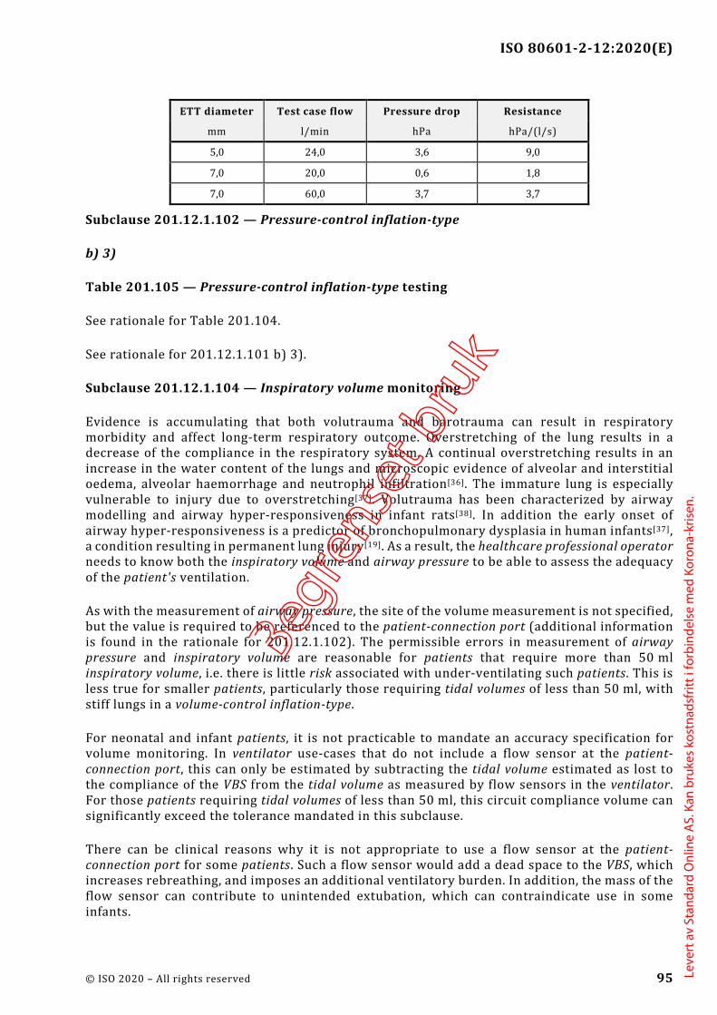
ISO 80601-2-12:2020(E)
© ISO 2020 – All rights reserved 95
ETT diameter Test case flow Pressure drop Resistance
mm l/min hPa hPa/(l/s)
5,0 24,0 3,6 9,0
7,0 20,0 0,6 1,8
7,0 60,0 3,7 3,7
Subclause 201.12.1.102 — Pressure-control inflation-type
b) 3)
Table 201.105 — Pressure-control inflation-type testing
See rationale for Table 201.104.
See rationale for 201.12.1.101 b) 3).
Subclause 201.12.1.104 — Inspiratory volume monitoring
Evidence is accumulating that both volutrauma and barotrauma can result in respiratory morbidity and affect long-term respiratory outcome. Overstretching of the lung results in a decrease of the compliance in the respiratory system. A continual overstretching results in an increase in the water content of the lungs and microscopic evidence of alveolar and interstitial oedema, alveolar haemorrhage and neutrophil infiltration[36]. The immature lung is especially vulnerable to injury due to overstretching[37]. Volutrauma has been characterized by airway modelling and airway hyper-responsiveness in infant rats[38]. In addition the early onset of airway hyper-responsiveness is a predictor of bronchopulmonary dysplasia in human infants[37], a condition resulting in permanent lung injury[19]. As a result, the healthcare professional operator needs to know both the inspiratory volume and airway pressure to be able to assess the adequacy of the patient's ventilation.
As with the measurement of airway pressure, the site of the volume measurement is not specified, but the value is required to be referenced to the patient-connection port (additional information is found in the rationale for 201.12.1.102). The permissible errors in measurement of airway pressure and inspiratory volume are reasonable for patients that require more than 50 ml inspiratory volume, i.e. there is little risk associated with under-ventilating such patients. This is less true for smaller patients, particularly those requiring tidal volumes of less than 50 ml, with stiff lungs in a volume-control inflation-type.
For neonatal and infant patients, it is not practicable to mandate an accuracy specification for volume monitoring. In ventilator use-cases that do not include a flow sensor at the patient-connection port, this can only be estimated by subtracting the tidal volume estimated as lost to the compliance of the VBS from the tidal volume as measured by flow sensors in the ventilator. For those patients requiring tidal volumes of less than 50 ml, this circuit compliance volume can significantly exceed the tolerance mandated in this subclause.
There can be clinical reasons why it is not appropriate to use a flow sensor at the patient-connection port for some patients. Such a flow sensor would add a dead space to the VBS, which increases rebreathing, and imposes an additional ventilatory burden. In addition, the mass of the flow sensor can contribute to unintended extubation, which can contraindicate use in some infants.
Begre
nset
bru
k
Leve
rt a
v St
anda
rd O
nlin
e A
S. K
an b
ruke
s ko
stna
dsfr
itt i
forb
inde
lse
med
Kor
ona-
kris
en.

ISO 80601-2-12:2020(E)
96 © ISO 2020 – All rights reserved
As a consequence, the accuracy specification for volume monitoring with tidal volumes of less than 50 ml has been left as a manufacturer disclosure.
Subclause 201.12.1.105 — Response of the ventilator to an increase in O2 concentration
It is important that changes in the delivered oxygen concentration can be made without major delay. This is especially relevant in cases where a rapid increase of the inspired oxygen concentration is necessary for patient care. For instance, it is common practice to preload the patient with high concentrations of oxygen for a brief period prior to open suctioning. Depending on the design of the ventilator and depending on the settings, significant delays can occur.
The committee could not develop a maximum delay as there are too many possible clinical scenarios. However, the healthcare professional operator needs to know how a ventilator will respond, particularly to a request for a sudden increase in oxygen concentration delivery.
As a result, a test method has been developed. The results of this test are required to be disclosed in the instructions for use so that an healthcare professional operator can effectively care for the patient.
Subclause 201.12.4.102 — Measurement of airway pressure
Additional information is found in the rationale for subclause 201.12.1.104.
The site in the VBS at which pressure is sensed varies from ventilator to ventilator. Generally, the manufacturer chooses one of two strategies:
measuring the airway pressure by direct sampling at the patient-connection port: or
indirectly estimating the pressure at the patient-connection port by measuring the pressures at two locations in the ventilator, on the inspiratory side of the VBS (at the “to patient” port) and on the expiratory side of the VBS (at the “from patient” port), and, after mathematical manipulation, averaging the two values.
Even if the first strategy is chosen, the actual pressure transducer will be located inside of the ventilator enclosure with narrow-diameter “plastic” tubing linking the pressure-sampling port at the patient-connection port to the sampling nipple on the pressure transducer. And for safety reasons a separate transducer will likely measure the pressure on the inspiratory side at the “to patient” port. The displayed airway pressure, however, is always expected to estimate accurately the true value that would be measured at the patient-connection port. Pressure measurement via the first strategy accurately reflects the true airway pressure within the error of the pressure transducer.
If the manufacturer selects the second strategy for the prediction of the true airway pressure, at least two methodologies can be used to arrive at estimates of this airway pressure.
Assuming that during inspiration the gas in the expiratory limb is essentially stagnant, one can conclude that the pressure measured on the expiratory side of the VBS reflects the true airway pressure. And conversely during exhalation, if one assumes stagnant conditions in the inspiratory limb, the pressure measured on the inspiratory side of the VBS can be taken as the airway pressure. However, if “bias” or “base” flows during inspiration and exhalation result in significant pressure losses across these individual limbs, these pressure losses need to be estimated. The airway pressure on the inspiratory side, ( )I
YP t , can be approximated by Formula (A.1):
Begre
nset
bru
k
Leve
rt a
v St
anda
rd O
nlin
e A
S. K
an b
ruke
s ko
stna
dsfr
itt i
forb
inde
lse
med
Kor
ona-
kris
en.

ISO 80601-2-12:2020(E)
© ISO 2020 – All rights reserved 97
𝑃𝑃YI(𝑡𝑡) = 𝑃𝑃I(𝑡𝑡) − �̇�𝑉I(𝑡𝑡) × 𝑅𝑅I (A.1)
where PI(t) is the measured pressure on the inspiratory side of the VBS,
�̇�𝑉I(𝑡𝑡) is the flow in the inspiratory limb, and
RI is the resistance of the inspiratory limb.
The airway pressure on the expiratory side, ( )EYP t , can be approximated by Formula (A.2):
𝑃𝑃YE(𝑡𝑡) = 𝑃𝑃E(𝑡𝑡) + �̇�𝑉E(𝑡𝑡) × 𝑅𝑅E (A.2)
where
PE(t) is the measured pressure on the expiratory side of the VBS,
�̇�𝑉E(𝑡𝑡) is the flow in the expiratory limb, and
RE is the resistance of the expiratory limb.
Taking the average of the inspiratory and expiratory pressures is shown in Formula (A.3), which arrives at the best estimate the airway pressure, ( )YP t .
( )( ) ( )+
=I EY Y
Y 2P t P t
P t (A.3)
The application of this last method requires a method to estimate RI and RE. With appropriate algorithms and regular cross checking of the two pressure transducers, the reliability and accuracy of ( )YP t is assured.
Subclause 201.12.4.103 — Measurement of expired volume and low-volume alarm conditions
It is desirable to have a fast responding measurement of volume and narrow alarm limits. However, as there is often considerable variation in a patient’s ventilatory pressures and volumes, narrow alarm limits inevitably lead to clinically insignificant alarm conditions. As a result, healthcare professional operators choose to set wide alarm limits to reduce the number of insignificant alarm conditions despite the fact that this can compromise patient care when there is a prolonged small change in their ventilation. Therefore, it is recommended that a ventilator be designed to initially use a lower priority alarm condition, which escalates to a higher priority if the alarm limit violation persists. The initial alarm condition priority and the priorities and timing of the escalation should be determined by the severity of the potential harm to the patient in combination with the length of time that the healthcare professional operator has to prevent the harm from occurring.
Subclause 201.12.4.104 — Expiratory end-tidal CO2 monitoring equipment
The monitoring of expiratory end-tidal CO2 is employed clinically as a surrogate for arterial CO2 tension. It therefore provides an alternative to monitoring expired tidal volume in assessing the adequacy of ventilation of the lungs. However, in the event of an occlusion or leak within the VBS, minute ventilation can be significantly reduced, while arterial CO2 rises. This can result in monitored end-tidal CO2 values that remain within the clinically acceptable range as the patient tidal volume is reduced below the level of physiologic dead space. The committee did not believe
Begre
nset
bru
k
Leve
rt a
v St
anda
rd O
nlin
e A
S. K
an b
ruke
s ko
stna
dsfr
itt i
forb
inde
lse
med
Kor
ona-
kris
en.

ISO 80601-2-12:2020(E)
98 © ISO 2020 – All rights reserved
that safety could be ensured through use of monitoring of end-tidal CO2 unless either monitoring inspiratory volume or expired volume was also in use.
It is not intended that this constrain a manufacturer to integrate the CO2 monitoring equipment into the ventilator. This allows for cases such as when the end-tidal CO2 monitoring equipment is integrated within a vital signs monitor from a separate manufacturer.
Subclause 201.12.4.105 — Maximum limited pressure protection device
When developing this edition of the document the committees carried out a re-evaluation of the current level of maximum limited pressure.
For several decades, international standards have specified the maximum limited pressure under single fault conditions of 125 hPa (125 cmH2O). However, limiting the lung pressure to 125 hPa (125 cmH2O) is not considered as lung protective. Therefore, it has been suggested that the maximum limited pressure should be reduced.
In a general population, the lung protective ventilation strategy involves keeping tidal volumes at 4 ml/kg to 6 ml/kg of predicted body weight (PBW) and preventing lung pressure from exceeding ~28 hPa (28 cmH2O) and “driving” pressures from exceeding 15 hPa (15 cmH2O). However even while applying this lung protective strategy as described above a limited number of patients need extremely high pressures at the patient-connection port (i.e. >80 hPa (80 cmH2O)) due to the extremely high resistance of their airways (e.g. patients suffering from an acute severe asthma).
Another clinical strategy considered is the use of a high set rate in order to minimize lung delta pressure while maintaining adequate CO2 removal. This requires a short inspiratory duration which in turn requires a high flowrate that requires a pressure at the patient-connection point that is significantly higher than the pressure in the patient lung.
High peak pressure at the patient-connection port can also be necessary for short periods for lung recruitment manoeuvres in obese patients.
The Figure AA.2 illustrates a pressure waveform during volume-control breath delivery to a patient with acute severe asthma. This shows a high peak pressure at the patient-connection port but a much lower pressure to which the lung of the patient is exposed. The high peak airway pressure at the patient-connection port is not injurious to the lung, as it does not reach the patient’s lung. However, if lung would be exposed to these non-acceptable pressures, the lung would be injured.
Considering the need to control the risk of a potential barotrauma (i.e. to reduce the maximum limited pressure the patient will be exposed to under single fault conditions as far as possible) but also considering the need to provide higher pressures under specific clinical conditions, the committees have developed a new concept which accommodates both the safe pressure limitation under single fault conditions for each individual patient and the clinical needs of higher pressures for a specific group of patients.
A review of incident databases did not identify any data demonstrating enhanced safety with a general pressure limitation lower than 125 hPa (125 cmH2O). Therefore increased patient safety would not be achieved by reducing the maximum limited pressure below 125 hPa (125 cmH2O), and such a reduction would prevent required treatment of certain patients and diagnoses.
Begre
nset
bru
k
Leve
rt a
v St
anda
rd O
nlin
e A
S. K
an b
ruke
s ko
stna
dsfr
itt i
forb
inde
lse
med
Kor
ona-
kris
en.

ISO 80601-2-12:2020(E)
© ISO 2020 – All rights reserved 99
This document defines a high pressure alarm condition, with an alarm limit that is configurable by the operator. Standard clinical practice is to set the high pressure alarm limit to a value that is a safe maximum peak airway pressure for the patient.
The maximum limited pressure is a secondary means of protection which becomes effective under single fault condition. In order to apply an appropriate level of maximum limited pressure, while not preventing effective ventilation with pressures necessary for the specific case, the committees decided to link the maximum limited pressure to the operator-configured high pressure alarm limit.
Key 1 airway pressure, Paw 4 maximum airway pressure, Paw,max 2 lung pressure, Plung 5 maximum lung pressure, Plung,max 3 BAP
Figure AA.2 — Pressure waveforms as a function of time during volume-controlled breath delivery to a patient with acute severe asthma
It is very common to use active controlled valves for limiting the maximum pressure. These valves open with a certain response time, which could result in a short pressure overshoot. When open the flow results in a pressure differential. Both effects together with the tolerance of the pressure control requires there to be a margin between the high pressure alarm limit and maximum limited pressure. Taking account of the technology available the committee determined that a margin of 20 hPa (20 cmH2O) between the high pressure alarm limit and maximum limited pressure would be sufficient.
In order to mitigate for unintentionally inappropriate settings, causing the high pressure alarm limit to go above at 60 hPa (60 cmH2O) or 20 hPa (20 cmH2O) above the operator-set pressure, an operator interaction requiring a clear and deliberate action, is introduced. See rationale to 201.12.4.106.
Begre
nset
bru
k
Leve
rt a
v St
anda
rd O
nlin
e A
S. K
an b
ruke
s ko
stna
dsfr
itt i
forb
inde
lse
med
Kor
ona-
kris
en.

ISO 80601-2-12:2020(E)
100 © ISO 2020 – All rights reserved
Subclause 201.12.4.106 — High airway pressure alarm condition and protection device
The high airway pressure alarm condition can occur in several scenarios, with different appropriate responses. It should be noted that it is implicit that in normal condition, the exhalation resistance of the VBS (including breathing circuit, filters, and exhalation valve) is sufficiently low so that the pressure can return to set BAP within one respiratory cycle of the end of a ventilator inspiration.
e)
Considering the reported incidents of patient harm associated with inappropriate setting of the high airway pressure alarm limit, the committees considered options to ensure that the alarm limit is set appropriately to reduce risk of barotrauma.
The great majority of patients, ventilated by a ventilator specified by this document, will not need more than a 60 hPa (60 cmH2O) high pressure alarm limit for sufficient ventilation. Therefore the committees determined that an unintentional setting in excess of 60 hPa (60 cmH2O) would be inappropriate.
In order to control the risk of unintentional settings, causing the high pressure alarm limit to be set above 60 hPa (60 cmH2O) or 20 hPa (20 cmH2O) above the operator-set pressure, an operator interaction requiring a clear and deliberate sequence of actions, was introduced to set the high pressure alarm limit to values in excess of 60 hPa (60 cmH2O) or 20 hPa (20 cmH2O) above the operator-set pressure.
f)
Patient cough
A cough is a transient forced expiration due to involuntary contraction of the abdominal muscles and opening of the glottis and vocal chords, resulting in a very rapid expiratory flow of short duration. This is most commonly triggered by pulmonary irritant receptors, and is a defensive mechanism that ejects foreign matter from the bronchi and trachea.
This action triggers a rapid but transient increase in pressure at the patient-connection port. The pressure elevation is generated by the patient respiratory muscles. In this scenario, it can be appropriate to transition to exhalation, as this would assist the forced expiration and clearance of foreign material. However, the volume of air ejected has come from the lungs, and the normal operation of the ventilator expiratory phase control of pressure would be sufficient to restore pressure to a value close to set BAP, within the normal exhalation period. There is no clinical reason to open a pressure-relief valve.
Patient forced expiration
In some cases, a patient can make a forced expiratory effort during the ventilator inflation phase, resulting in a pressure increase at the patient-connection port. As this is a patient-generated pressure, the same rationale applied to cough would apply to this scenario, and transition to the exhalation phase is an appropriate and sufficient response. Even in the worst case, the exhaled volume would be unlikely to exceed twice the normal exhaled volume, and the time required to reduce the pressure to set BAP would not significantly exceed one respiratory cycle.
Inappropriate volume for patient compliance
Begre
nset
bru
k
Leve
rt a
v St
anda
rd O
nlin
e A
S. K
an b
ruke
s ko
stna
dsfr
itt i
forb
inde
lse
med
Kor
ona-
kris
en.

ISO 80601-2-12:2020(E)
© ISO 2020 – All rights reserved 101
In a volume-control or volume-targeted ventilation-mode, pressure can exceed the high airway pressure alarm limit due to a reduced pulmonary compliance. In this scenario it would be preferable to apply a pressure limitation (with a threshold less than the high airway pressure alarm limit). However in the absence of this function, the appropriate action would be to transition to the exhalation phase. As the inspiratory volume is not increased, there is no reason why the normal operation of the ventilator in the expiratory phase would not reduce the airway pressure to set BAP within one respiratory cycle.
Inspiratory limb occlusion
In this single fault condition, the patient is not subject to high pressure. Ventilators that do not incorporate a pressure monitoring line from the patient-connection port might be unable to differentiate this from a high airway pressure state. Because the patient is not subjected to the high airway pressure, the action defined in 201.12.4.108 (obstruction alarm condition) is appropriate to control the risk.
Expiratory limb, breathing system filter or expiratory valve occlusion
For most software-controlled ventilators, this only results in a high airway pressure alarm condition if it occurs during the expiratory phase, as the exhalation valve remains closed during ventilator inspiration. In some cases (such as a ‘pressure limited’ ventilation-mode), the patient pressure can exceed the alarm limit if the occlusion prevents the maximum limited pressure protection device from operating.
Terminating gas output port flow – either by terminating the inflation phase, or terminating the base or continuous flow – causes the pressure to stop increasing, but might not result in the pressure falling below the alarm limit. This constitutes the ‘action to cause the pressure to start to decline’. If the pressure fails to return close to set BAP within one respiratory cycle, this is evidence that the expiratory resistance is excessive, and the ventilator should provide an alternative means to relieve the pressure. Typically this would involve opening some form of ‘safety valve’ in the inspiratory part of the VBS. Assuming that the inspiratory limb of the circuit has comparable resistance to the expiratory limb, it can then take one further respiratory cycle to restore pressure at or below set BAP. Hence the committees have specified that the pressure is required to be reduced to set BAP, or atmospheric pressure level, within no more than two respiratory cycles or 15 s.
Flow delivery ‘fails open’
In single fault conditions such as a mechanical failure of a pressure regulator or a flow control valve, or a failure of software control of a flow source, resulting in uncontrolled flow of gas to the ventilator gas output port, transition to the expiratory phase (which opens the exhalation valve) should be sufficient to control the risk. However, the pressure might not reach the limit within 200 ms. If the pressure remains above the high airway pressure alarm limit (for example because of a catastrophic flow valve failure) it can then be appropriate to also open some form of pressure-relief valve to divert the gas output port flow and restore the patient-connection port to atmospheric pressure.
Begre
nset
bru
k
Leve
rt a
v St
anda
rd O
nlin
e A
S. K
an b
ruke
s ko
stna
dsfr
itt i
forb
inde
lse
med
Kor
ona-
kris
en.
ISO 80601-2-12:2020(E)
102 © ISO 2020 – All rights reserved
h)
Atmospheric pressure
In normal condition, termination of ventilator inspiration, and the normal action of the expiratory valve, allows pressure to be relieved to PEEP within one respiratory cycle without loss of control of PEEP. Normal condition would include any patient-generated effect. However, if there is a single fault condition, such as an obstruction of the breathing circuit or a flow delivery fault, other means can be required to reduce the pressure, and in this scenario it is not expected that the ventilator is able to maintain control of PEEP.
Set BAP level
As noted above, the worst-case time required to reduce the airway pressure to a value less than or equal to set BAP is two respiratory cycles. To account for the possibility that the mandatory set rate has been set to a value significantly less than the patient’s normal resting breathing rate, the committees have limited the recovery time to a maximum of 15 s. This reflects literature that shows typical breathing rates in adults[42], including geriatric populations[43], that are rarely less than 10 breaths/min, and hence would require no more than 12 s for two respiratory cycles.
Subclause 201.12.4.108 – Obstruction alarm condition
Sustained elevated airway pressure levels can cause hazardous increases in intra-thoracic pressure. Such pressure increases can result in decreased venous return, reduced cardiac output and a subsequent drop in arterial blood pressure. Obstruction of the expiratory limb is the most common obstruction in a ventilator. The obstruction of the expiratory limb alarm condition should be designed to detect promptly a reduced expiratory flow due to an increased resistance in the expiratory limb.
The nature or duration of an occlusion in the expiratory limb of the VBS cannot be predicted. Assuming that the occlusion is severe and the safety valve opens quickly, the patient is not exposed to potentially injurious high pressures, although at the likely expense of the loss of PEEP. Further inspirations, whether or not assisted by the ventilator, necessitate rebreathing the previously exhaled gas trapped in the inspiratory limb. Given these considerations and their consequences, the associated alarm condition is required to be at least medium priority. Even if the ventilator is highly sophisticated, the presence of an occlusion in the expiratory limb of the VBS represents a significant corruption of the ventilator’s ability to provide essential respiratory support to the patient, which requires prompt action by the healthcare professional operator.
Examples of causes for continuing airway pressure include a malfunctioning expiratory valve, kinked tubing and expiratory filter blockage. Nebulised[16] drugs can block expiratory filters within a short time.
Other consequences of incomplete expiration (increased peak airway pressure or decreased ventilation) can be detected and indicated by other alarm conditions required by this document. Practice shows that clinically used alarm limits are not always sensitive enough to provide early and specific detection of this potentially hazardous situation.
Subclause 201.12.4.109 — Disconnection alarm condition
Disconnection of the ventilator breathing system is a frequent occurrence in the critical care environment, and yet the only reference on the previous edition of this document is a reference
Begre
nset
bru
k
Leve
rt a
v St
anda
rd O
nlin
e A
S. K
an b
ruke
s ko
stna
dsfr
itt i
forb
inde
lse
med
Kor
ona-
kris
en.
ISO 80601-2-12:2020(E)
© ISO 2020 – All rights reserved 103
in 201.13.2.101 to disruption of the gas delivery to the patient-connection port from the ventilator.
It is recognized that disconnection leads to a loss of gas exchange, with the possibility of significant harm or death[44]. Many current critical care ventilators generate a technical alarm condition when this occurs. This amendment adds a mandatory requirement to provide such a disconnection alarm condition.
Implementation of a disconnect alarm condition can use a variety of technological means to detect gas flow into and out of the lungs, and these can differ between different groups of patients. Where the disconnect alarm condition detection mechanism uses information from one or more external sensors, such as for expired CO2, the requirement from Clause 13 of the General Standard for single fault safety applies. Loss of information from an external sensor would need to be assessed as a single fault condition.
Detection of disconnection of the breathing gas pathways between the ventilator and the patient-connection port, or disconnection at the patient-connection port, is mandatory.
In some patient groups, and particularly in neonates ventilated with a narrow lumen endotracheal tube, it might not be practicable to reliably detect decannulation without using a sensor placed between the patient-connection port and the airway device. For example an expiratory flow or end-tidal CO2 sensor.
However there can be clinical reasons why this is not appropriate. Use of either a flow sensor or a mainstream EtCO2 sensor adds dead space to the airway device, which can be very significant relative to the desired tidal volume. This would increase rebreathing of exhaled gases, and impose an additional ventilatory burden. This has been demonstrated to prolong weaning time and worsen patient outcome[58].
In addition, the mass of the sensor attached to the airway device can increase the incidence of unintended extubation.
When using a diverting (sidestream) expired CO2 monitor, the monitor removes a fixed flowrate of gas from the patient-connection port. This can exceed the spontaneous inspiratory flow for an infant patient, and thereby prevent use of patient-triggered ventilation-modes, resulting in a higher imposed work of breathing and patient-ventilator asynchrony.
As a consequence, the operator needs to retain the ability to select which monitoring devices are attached to the VBS, while also being aware of any limitation that the adopted configuration imposes on the operation of the alarm system. For this reason, this has been added to Clause 206 to ensure that the usability process is applied to this scenario.
Critical care ventilators are intended for use in the critical care environment. These settings provide specialized care for patients with conditions that can be life-threatening and who require constant monitoring in a professional healthcare facility. Not all patients who are cared for in the critical care environment are ventilator-dependent, and as a result critical care ventilators can be used to augment the ventilation of spontaneously breathing patients.
Although some manufacturers have chosen to provide separate ventilation-modes for ventilator-dependent and non-ventilator-dependent patients, this is discouraged as it leads to operator confusion. According to ISO 19223, ventilation-modes are classified by the types of inflations that
Begre
nset
bru
k
Leve
rt a
v St
anda
rd O
nlin
e A
S. K
an b
ruke
s ko
stna
dsfr
itt i
forb
inde
lse
med
Kor
ona-
kris
en.
ISO 80601-2-12:2020(E)
104 © ISO 2020 – All rights reserved
are provided, the pattern of initiation, and independently of the intended patient or airway interface.
In those patients who are not ventilator-dependent, disconnection cannot require prompt attention from the operator. Alarm fatigue is well-documented in the clinical setting[45], and can lead to delayed response to those alarm signals that really are critical, including alarm signals from the ventilators used for ventilator-dependent patients[46]. It is desirable to allow the operator to inactivate this alarm condition to avoid distracting caregivers from other more critical events.
This document does not address how the operator confirms whether a particular patient is ventilator-dependent prior to inactivating the disconnection alarm signals. Many implementations are possible, for example, this information can be captured during patient setup; or it can be included as a prompt during the process of inactivation. The manufacturer is required to perform usability testing in order to validate the effectiveness of their implementation.
Subclause 201.12.101 — Protection against accidental adjustments
Unacceptable risks to the patient can occur as a result of accidental adjustments of operating controls or turning off the ventilator. To control this risk, the operator-equipment interface should be designed to prevent accidental adjustments. The usability engineering process is used to ensure that these risks are reduced to acceptable levels. Example methods could include mechanical risk control techniques such as locks, shielding, friction-loading and detents; pressure-sensitive finger pads; capacitive finger switches; and microprocessor-oriented “soft” risk controls; and a specific sequence of key or switch operations.
Subclause 201.13.2.101 — Additional specific single fault conditions
a)
Disruption of the gas delivery to the patient independent of the root cause for the disruption (e.g. by disconnection or blockage of the inspiratory breathing / tubing system) is the most reasonably foreseeable event in the daily practice of ventilation around the world that might quickly lead to serious irreversible injury or the death of a ventilator-dependent patient.
b)
Disruption of the gas flow pathway between the patient and the ventilator independent of the root cause for the disruption (e.g. by disconnection or blockage of the expiratory breathing / tubing system) is the most reasonably foreseeable event in the daily practice that, depending on the VBS in use, might lead to pressure loss. This can consequentially lead to the inability to build up a VBS pressure sufficient to ventilate the patient, which in further consequence might lead to serious irreversible injury or the death of a ventilator-dependent patient.
c)
Operation of a ventilator without an operator-detachable breathing system filter in place is considered reasonably foreseeable when considering those parts of the VBS that might become contaminated with body fluids or by contaminates carried by expired gases. If a ventilator can operate without the breathing system filter, then one has to assume that it has been operated without the breathing system filter and therefore those parts of the VBS might have been contaminated. Additional information is found in the rationale for 201.11.6.6.
Begre
nset
bru
k
Leve
rt a
v St
anda
rd O
nlin
e A
S. K
an b
ruke
s ko
stna
dsfr
itt i
forb
inde
lse
med
Kor
ona-
kris
en.

ISO 80601-2-12:2020(E)
© ISO 2020 – All rights reserved 105
Increased resistance and blockage of a breathing system filter when used together with nebulization[16] or humidification is also considered as failure of an operator-detachable breathing system filter.
d)
Operation of a ventilator using an operator-detachable remote control or monitoring module is considered as a state of the art option of today. Independent of how the communication between the “ventilator module” and the remote control or monitoring module is facilitated (e.g. wired or wireless) this communication needs be so designed and constructed that a failure or loss of this communication does not cause an unacceptable risk to the patient. Further this communication (e.g. between the “ventilator module”, the remote control or monitoring module, the distributed alarm system or a simple remote alarm signal communicator) also needs designed as single fault safe.
Subclause 201.13.2.102 — Failure of one gas supply to a ventilator
This subclause addresses the hazardous situation created when an entire unit (e.g. the whole critical care unit or all of the operating theatres) experiences simultaneous failure of multiple ventilators caused by the loss of a single pressurized gas source where at least one gas source is provided by a pressurized medical gas pipeline system.
EXAMPLE 1 A ventilator is connected to both air and oxygen medical gas pipeline systems and one of the medical gas pipeline systems fails. The ventilator then uses the other medical gas pipeline system to supply gas.
EXAMPLE 2 A blower-based ventilator is connected is to an oxygen medical gas pipeline system and that medical gas pipeline system fails. The ventilator then uses the room air provided by its blower.
Subclause 201.13.2.103 — Independence of ventilation control function and related risk control measures
This requirement prevents the use of a monitoring device to control an actuator that would lead to an undetected malfunction of the actuator in case of monitoring failure.
Subclause 201.13.2.104 — Failure of functional connection to a ventilator control or monitoring means
Independent how the functional connection between the “ventilator module” and the remote control or monitoring module is facilitated (e.g. wired or wireless) this functional connection needs to be so designed and constructed that a failure or loss of the functional connection does not cause an unacceptable risk to the patient.
First of all this means that the safety of the patient is not degraded by the loss of the functional connection, (i.e. the “ventilator module” continues to ventilate the patient without any change of the ventilation parameters, without any change of setting of safety means and without any change of the setting of alarm limits). Further, the healthcare professional operators in both locations where these modules are located need to be made aware by alarm signals about the loss of this functional connection (i.e. there is a need for alarm signals on both sides of the functional connection—at the “ventilation module” and on any other remote control or monitoring module or the distributed alarm system or the simple remote alarm signal generator).
Begre
nset
bru
k
Leve
rt a
v St
anda
rd O
nlin
e A
S. K
an b
ruke
s ko
stna
dsfr
itt i
forb
inde
lse
med
Kor
ona-
kris
en.
ISO 80601-2-12:2020(E)
106 © ISO 2020 – All rights reserved
Subclause 201.15.3.5.101.1 — Shock and vibration (robustness)
The intention of these tests is to assess mechanical stresses on the ventilator in normal use and not to assess the suitability of the design for the expected service life or fatigue.
ME equipment, including ventilators, in normal use, used within a professional healthcare facility, or home healthcare environment will be subjected to mechanical stresses (e.g. vibration, shock) and could randomly be subjected to additional stresses. Therefore, ME equipment intended to be used in a professional healthcare facility needs to be robust enough to withstand the vibration and shock testing described as level 7M1 by IEC 60721-3-7[47]. IEC 60721-3-7 indicates that this class applies within, and direct transfer between, locations with only low-level vibrations, or with medium-level shocks. Careful handling and transfer of products is expected in these environments.
In reviewing the random vibration tests of IEC 60068-2-64:2008, the committee determined that the environment included careful handling in vehicles (including airborne vehicles). Since a critical care ventilator is not intended for such environments, the maximum frequency of the acceleration amplitude was limited to 500 Hz which is more reflective of non-vehicle environments.
Subclause 201.15.3.5.101.2 — Shock and vibration for a transit-operable ventilator during operation
Transit-operable ventilators (those intended to operate while the patient is being transported within a healthcare facility) are expected to maintain basic safety and essential performance while they are being moved. Some degradation is permitted, but the patient is expected to continue to be adequately and safely ventilated. Rationale for 202.8.101 contains additional information regarding appropriate acceptance criteria for essential performance.
Subclause 201.16.2.101 — Additional general requirements for accompanying documents of an ME system
Many respiratory gas humidifiers control their humidification output by servo controlling the temperature of a water bath to achieve a set gas temperature at the humidifier chamber outlet. This temperature is frequently defined to be a function of gas flowrate as measured by the humidifier, and is defined to target a desirable absolute humidity – the rate of evaporation of water and the rate of heat transfer from the water to the air are closely correlated. This works provided the input gas temperature is below a threshold. For example, for one leading manufacturer of humidifiers, the water vapour output starts to reduce when the input gas temperature exceeds 27 °C.
A ventilator that incorporates a blower to provide a source of breathing air drawn from an air intake inevitably increases the temperature of the air above the intake temperature. The extent of this rise in temperature will depend on the set FiO2 (and hence the proportion of the breathing gas that has been compressed), the blower outlet pressure (which can significantly exceed the ventilator gas output port pressure), the ventilator set rate, BAP, and set Δ inspiratory pressure or tidal volume, and the efficiency of the blower technology used.
This has been confirmed in published bench study[59]. This study confirmed that with unfavourable conditions, specifically humidifier chamber inlet gas temperatures above 37 °C, humidifier output could fall well below recommended minimum levels of 20 mgH2O/l.
Begre
nset
bru
k
Leve
rt a
v St
anda
rd O
nlin
e A
S. K
an b
ruke
s ko
stna
dsfr
itt i
forb
inde
lse
med
Kor
ona-
kris
en.

ISO 80601-2-12:2020(E)
© ISO 2020 – All rights reserved 107
For a ventilator capable of generating an elevated gas temperature at the gas output port, the responsible organization needs to have information available to allow them to determine whether the humidifier is likely to remain effective.
Subclause 201.101.1 — Protection against reverse gas leakage
These conditions are necessary to maintain patient safety by protecting the medical gas pipeline system from contamination via reverse flow.
The basic requirements of this subclause were introduced into standards more than a decade ago because of the harm due to reverse gas leakage that was known to have occurred in connection with medical devices that use multiple gas sources.
With devices fitted with multiple gas intake ports for the same gas, the hazardous situation results from the undetected loss of backup gas supplies due to back leakage into the primary supply. With gas intake ports for different gasses, the hazard is contamination of one gas source by gas from another source. The contamination hazard is particularly likely to occur while the medical device is left in a condition where it is connected to the gas supplies but is not drawing flow from the gas supply system.
Ventilators are frequently equipped with multiple gas intake ports either to achieve a greater flow or to use a local backup supply, e.g. a gas cylinder, in parallel with a medical gas pipeline system supply. With such systems the backup supply could be depleted prematurely during use or, when connected but not in use, could deplete without detection and not be available when required in an emergency.
With a ventilator equipped with more than one different gas intake port, even very small leakages from one of the gas systems to the other can cause considerable contamination in a medical gas pipeline system over extended periods during which little flow is withdrawn.
More than 10 y of experience has demonstrated that these requirements are effective risk control measures.
Subclause 201.101.2.2 — Filter
The intention of filtration of the gas from the high-pressure inlet port is to protect the sensitive components (e.g. flow sensors) of the ventilator gas pathways from particles. This gas is provided from a medical gas pipeline systems or from gas cylinders.
The standards for high-pressure oxygen compatibility[8] and pressure regulators[29] require input filtering that prevents particles greater than 100 μm from entering. This filtering minimizes particles as means to control the risk of ignition by high velocity particles in a pressurized, oxygen enriched environment. These standards also emphasize the need to proper filter material.
Despite these requirements, in the following cases particles with larger sizes could occur:
particles collected in high-pressure input ports and port connectors;
high-pressure input ports of ventilators while disconnected; or
malfunction of medical gas pipeline systems, medical air compressors, oxygen concentrators or filters.
Begre
nset
bru
k
Leve
rt a
v St
anda
rd O
nlin
e A
S. K
an b
ruke
s ko
stna
dsfr
itt i
forb
inde
lse
med
Kor
ona-
kris
en.

ISO 80601-2-12:2020(E)
108 © ISO 2020 – All rights reserved
Depending on the design of a specific ventilator (e.g. in case that particle-sensitive sensors are used) significantly smaller filter sizes than 100 μm can be required.
Subclause 201.101.3.1 — General
Non-standard VBS connectors can represent an unacceptable risk as attempts are made to fit a standard VBS to a ventilator in an emergency situation. Non-standard VBS connectors can cause leaks if used with similar but not compatible connectors.
Subclause 201.101.3.2.5 — Accessory port
The use of Luer taper or Luer-lock connectors conforming with ISO 594-1:1986[49], ISO 594-2[50] or ISO 80369-7:2016[51] are not permitted for use for connection with the gas pathways of a VBS as there are several case reports of accidental connection with intravenous fluids and parenteral and enteral feeding solutions causing serious morbidity and mortality due to aspiration of these foreign substances into the lungs.
Subclause 201.102.1 — General
It is the responsibility of the manufacturer of a ventilator breathing system, its parts or accessories to verify that their product conforms with the requirements of this document.
Subclause 201.102.4 — Water vapour management
Water management refers to the complete process by which moisture, in the form of water vapour, is added to the breathing gas delivered to the patient’s lungs and the process by which humidified breathing gas is conducted back to the ventilator’s expiratory system and exhausted to the room. Intrinsic to this process is the necessity to remove bulk water due to condensation of moisture attributable to pressure and temperature changes in the VBS. Even if breathing gas reaches the patient-connection port without any added moisture, the expired breathing gas directed back to the ventilator will contain some moisture. Water management in the VBS requires attention, whether or not the VBS contains an active humidifier, with or without heated wires in the inspiratory or the expiratory limbs of the VBS, or a passive or an active HME at the patient-connection port.
Proper management of the patient’s airway secretions and mucociliary transport system requires that the ventilator compensate for the humidity deficit caused by intubation, which bypasses the upper airways where the normal humidification process would begin. Excess moisture delivered to the patient-connection port can flood the cilia located in the bronchial airways, diminishing their ability to move mucus toward the trachea. On the other hand insufficient humidification of the inspired breathing gas dries the bronchial airways, which leads to thickening of the mucous secretions and likely increased airway resistance or worse. A balanced approach to humidification is needed to maintain healthy cilia. Liquefied mucus can be readily aspirated using a suction catheter.
Optimal humidification of the patient’s airways results from an understanding of the physics of the techniques chosen to add water vapour to the inspiratory gas stream. Depending on the system selected for delivering humidified breathing gas to the patient (for example, active vapour humidifier with or without heated wires, a passive or active HME), condensate can accumulate in the inspiratory limb of the VBS. If condensation occurs, the VBS will need to provide a method by which the liquid can be removed.
Begre
nset
bru
k
Leve
rt a
v St
anda
rd O
nlin
e A
S. K
an b
ruke
s ko
stna
dsfr
itt i
forb
inde
lse
med
Kor
ona-
kris
en.

ISO 80601-2-12:2020(E)
© ISO 2020 – All rights reserved 109
In all but the most unusual circumstances, gas leaving the alveoli is saturated at 37 °C. Rainout persists as the moist gas cools and moves toward the patient-connection port, and is conducted back to the ventilator. If an HME is fitted at the patient-connection port, approximately 50 % to 70 % of the water vapour will be trapped in the HME. Whatever the configuration of the expiratory limb of the VBS, the water vapour content of the exhaled gas will be significant, nearing saturation. Without heated wires, the returning gas cools, causing significant condensation. As in the inspiratory limb, this liquid needs to be removed. The presence of heated wires in the expiratory limb lessens or eliminates condensation before the expired gas enters the gas return port of the ventilator, but from this point to the exhaust port the gas tends to cool further, so more moisture will condense. The VBS needs to include some means to manage this additional condensed water.
Subclause 201.102.7.1 — Leakage from complete VBS
Assuming that the leakage flow can be modelled as if an ideal orifice were producing it, then the leakage flowrate would follow Formula (AA.4).
= ×leakQ G P (AA.4)
where
G is the orifice conductance and
P is the driving pressure.
Using the leakage limits given in Table AA.1 and Formula (AA.4), the orifice conductance G can be calculated for each of the tidal volume ranges. For example, the leakage limit for tidal volumes ≥300 ml is 200 ml/min at a pressure of 50 cmH2O, which yields a value for G of 28,28 ml/(min·hPa1/2). Conductance values for the other tidal volume ranges can be similarly calculated. Table AA.1 summarizes these results.
Table AA.1 — Calculated conductance values by tidal volume range
Tidal volume range Leakage limit Pressure, P Calculated conductance, G
ml ml/min hPa (cmH2O) ml/(min·hPa1/2)
Vtidal ≤ 50 50 20 11,18
50 ≥ Vtidal ≥ 300 100 40 15,81
Vtidal ≥ 300 200 50 28,28
Using these calculated conductances, it is then possible to find the corresponding VBS leakage limit at any pressure. Figure AA.3 demonstrates these relationships.
Using Figure AA.3, one can derive the 60 hPa (60 cmH2O) VBS leakage flowrate limits. This is the pressure at which most of the operator-accessible parts of the VBS are specified for leakage flowrate.
for Vtidal ≤ 50 ml, Qleak = 87 ml/min
for 50 ml ≥ Vtidal ≥ 300 ml, Qleak = 122 ml/min
for Vtidal ≥ 300 ml, Qleak = 219 ml/min
Begre
nset
bru
k
Leve
rt a
v St
anda
rd O
nlin
e A
S. K
an b
ruke
s ko
stna
dsfr
itt i
forb
inde
lse
med
Kor
ona-
kris
en.
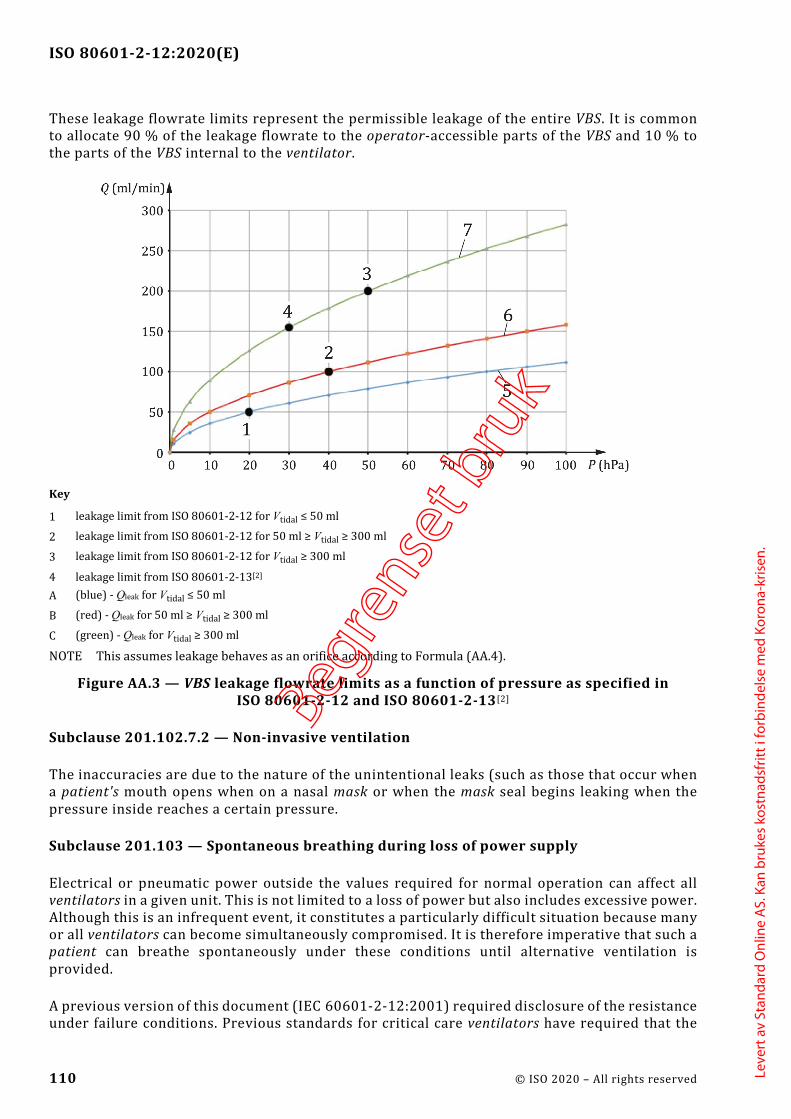
ISO 80601-2-12:2020(E)
110 © ISO 2020 – All rights reserved
These leakage flowrate limits represent the permissible leakage of the entire VBS. It is common to allocate 90 % of the leakage flowrate to the operator-accessible parts of the VBS and 10 % to the parts of the VBS internal to the ventilator.
Key
1 leakage limit from ISO 80601-2-12 for Vtidal ≤ 50 ml
2 leakage limit from ISO 80601-2-12 for 50 ml ≥ Vtidal ≥ 300 ml
3 leakage limit from ISO 80601-2-12 for Vtidal ≥ 300 ml
4 leakage limit from ISO 80601-2-13[2] A (blue) - Qleak for Vtidal ≤ 50 ml
B (red) - Qleak for 50 ml ≥ Vtidal ≥ 300 ml
C (green) - Qleak for Vtidal ≥ 300 ml
NOTE This assumes leakage behaves as an orifice according to Formula (AA.4).
Figure AA.3 — VBS leakage flowrate limits as a function of pressure as specified in ISO 80601-2-12 and ISO 80601-2-13[2]
Subclause 201.102.7.2 — Non-invasive ventilation
The inaccuracies are due to the nature of the unintentional leaks (such as those that occur when a patient's mouth opens when on a nasal mask or when the mask seal begins leaking when the pressure inside reaches a certain pressure.
Subclause 201.103 — Spontaneous breathing during loss of power supply
Electrical or pneumatic power outside the values required for normal operation can affect all ventilators in a given unit. This is not limited to a loss of power but also includes excessive power. Although this is an infrequent event, it constitutes a particularly difficult situation because many or all ventilators can become simultaneously compromised. It is therefore imperative that such a patient can breathe spontaneously under these conditions until alternative ventilation is provided.
A previous version of this document (IEC 60601-2-12:2001) required disclosure of the resistance under failure conditions. Previous standards for critical care ventilators have required that the
Begre
nset
bru
k
Leve
rt a
v St
anda
rd O
nlin
e A
S. K
an b
ruke
s ko
stna
dsfr
itt i
forb
inde
lse
med
Kor
ona-
kris
en.

ISO 80601-2-12:2020(E)
© ISO 2020 – All rights reserved 111
pressure drop be less than 6 hPa (6 cmH2O) at 60 l/min for adults. Patients in a critical care unit usually don't generate such high inspiratory flows. Considering this and that accessories can be placed in the VBS, the committee came to the conclusion that this value is unnecessarily design-restrictive. In addition, spontaneous breathing is only needed to bridge the time until alternative ventilation is provided. The committee came to the conclusion that a mere disclosure is not sufficient. The chosen values are regarded as more realistic and sufficient for this infrequent event and were tailored to the intended range of tidal volumes.
Subclause 201.104 — Indication of duration of operation
Ventilators require maintenance for continued safe use. A practicable means to ensure that this information is available to the operator or the responsible organization is to require that the ventilator keep track of how long it has been in operation.
Subclause 201.105.2 — Connection to electronic health record
Electronic documentation of patient care interventions is rapidly becoming the standard of care. The primary motivations are to improve the quality of care for an individual patient through accurate and complete documentation, and to improve the completeness and accuracy of aggregate data to facilitate continuous quality improvement. In some countries, there is a governmental directive to provide electronic health records by 2015[52]. Electronic data transmission to the electronic health record is essential to meet this requirement. Annex BB contains information that manufacturers can find useful as requirements for data interfaces.
The data transmission should be capable of being provided with such a functional connection in accordance with ASTM F2761-09[26].
Subclause 201.105.3 — Connection to distributed alarm system
Patients who are ventilator-dependent are usually located in clinical environments that are staffed with healthcare professional operators in sufficiently close proximity to hear alarm signals coming from the patient's room. However, the layout of some critical care units is such that a distributed alarm system is needed to ensure that the operator can hear the alarm signal. Patients also can be in enclosed (positive or negative pressure) isolation rooms. In these settings, it can be difficult or impossible for healthcare professional operators to hear alarm signals. As a result, an appropriate response can be delayed with catastrophic results. A distributed alarm system facilitates delivery of alarm signals to remotely located healthcare professional operators, thereby permitting a timely response and intervention to support patient care[53].
The data transmission should be capable of being provided with a functional connection in accordance with ASTM F2761-09[26].
Subclause 201.107 — Timed ventilatory pause
Pausing artificial ventilation is necessary for certain clinical procedures.
EXAMPLE Chest x-ray at a healthcare professional operator-chosen level of inflation, chest x-ray at end-expiration, measuring central venous pressure or cardiac output, measuring respirophasic blood pressure variation, suctioning the airway, turning the patient.
Currently, in order to avoid nuisance alarm signals and to avoid cycling the ventilator while the VBS is disconnected from the patient, healthcare professional operators usually turn off the
Begre
nset
bru
k
Leve
rt a
v St
anda
rd O
nlin
e A
S. K
an b
ruke
s ko
stna
dsfr
itt i
forb
inde
lse
med
Kor
ona-
kris
en.

ISO 80601-2-12:2020(E)
112 © ISO 2020 – All rights reserved
ventilator and thereby incur the risk of undetected prolonged apnoea by subsequently forgetting to turn the ventilator back on.
Alternatively, the x-ray technicians manually attempt to synchronize chest x-ray exposure to ventilatory phase through hand-eye coordination, with varying effectiveness. Automated synchronization of x-ray exposure and ventilation would provide clinical benefits[54].
In addition, there are situations where, to permit the minimum disruption of ventilation, the initiation of the ventilatory pause needs to come from external equipment. This is particularly important for those procedures, e.g. high doses of radiation, where the healthcare professional operator needs to evacuate the immediate area or when manual synchronization would be less effective[54].
As part of the risk management process, special attention should be paid to ensuring that the patient's lungs remains adequately ventilated when either externally generated or repetitive ventilatory pauses occur.
The expiratory pause should be capable of being provided with a functional connection in accordance with ASTM F2761-09[26].
Subclause 202.4.3.1 — Compliance criteria
It is not the intent of the committee to require that the immunity tests be performed multiple times (e.g. with a volume-control inflation-type and pressure-control inflation-type at several tidal volumes), but that the manufacturer should determine which inflation-type and tidal volume represents the worst case for a given immunity test and use those conditions.
Subclause 202.8.101 — Additional general requirements
The committees recognized that during environmental stress (for example, shock, vibration, electromagnetic disturbances) ventilator performance can degrade. In such a situation, the duration of altered performance would be about minutes to, at most, few tens of minutes. Shock and drop disturbances can be even shorter (i.e. less than 100 ms). The question then became how to express the percent change in pressure and volume performance that would not cause harm to a patient during a brief interval of environmental stress. In today’s intensive care unit (ICU) environment of Lung Protective Ventilation (LPV) in which according to clinical research, caution should be exercised when total lung pressures and inflation volumes encroach on pressures of 35 cmH2O and volumes of 12 ml/kg, respectively. The committees examined various scenarios in which pressures and volumes exceed the above values. High-side deviations in the range of 5 % to 10 % offer little relief because the error of the monitoring falls in this same range. The issue, therefore, is what higher deviation is acceptable. The committees considered two situations:
1) an average of 25 % over 30 consecutive inflations; and
2) a single inflation deviation of 35 %.
With respect to a total lung pressure of 35 cmH2O and tidal volume of 12 ml/kg, the average values equal 43,8 cmH2O and 15 ml/kg, respectively. Given that the maximum duration of a few tens of minutes (i.e., ≤30 min) a patient would be expected to tolerate these pressure and volume deviations without undue risk. The committees recognize that environmentally induced pressure and volume deviations would be uneven. Thus, maximum single deviations of 35 % yield values of 47,2 cmH2O and 16,2 ml/kg. Although these values intrude into a range not recommended for
Begre
nset
bru
k
Leve
rt a
v St
anda
rd O
nlin
e A
S. K
an b
ruke
s ko
stna
dsfr
itt i
forb
inde
lse
med
Kor
ona-
kris
en.
ISO 80601-2-12:2020(E)
© ISO 2020 – All rights reserved 113
continuous ventilation, random values of this magnitude over a brief interval are not expected to create undue harm.
Subclause 206.102 — Training
The modern critical care ventilator is a complex life-sustaining ME equipment whose use requires specific training for each manufacturer's make and model. Different manufacturers often refer to similar ventilation-modes by different names, and, although in principle similar to another manufacturer's ventilator, their ventilation-mode is unique in sometimes minor and sometimes complex ways. It is essential, therefore, that however experienced the operator, every person involved with its operation and setup is fully trained in the ventilator’s operational characteristics, in particular its controls, capabilities and limitations, prior to any use.
Subclause 208.6.8.4.101 — Additional requirements for termination of alarm signal inactivation
Permitting very long pauses of alarm signals can be hazardous for the patient since the healthcare professional operator will not be notified of the existence of an alarm condition. However, patient management often requires delicate procedures that can be disrupted by auditory alarm signals. Therefore, extending audio paused by healthcare professional operator action is useful to prevent the ventilator from disturbing the healthcare professional operator or others in the vicinity (e.g. surgeon or cardiologist) in the patient’s room.
Ventilators should be equipped with an audio paused capability that permits the healthcare professional operator to pause the auditory alarm signals prior to the creation of an alarm condition. Such a capability permits the healthcare professional operator to minimize nuisance auditory alarm signals in situations that are known to be associated with creation of nuisance alarm conditions. A ‘planned’ disconnect is a common situation where this capability is needed. Examples include open suctioning, breathing system filter change, or insertion of a medication treatment. A closed suctioning ventilator-operational mode should also include such a capability.
Subclause 208.6.12.101 — Additional requirements for alarm system logging
Optimal management of a patient requires the capability to review the history of important alarm conditions. This is a more reasonable means of risk control in the critical care environment than latching alarm signals. Additional information is found in IEC 60601-1-8:2006+AMD1:2012, Annex A, for 6.12 – alarm condition logging.
Begre
nset
bru
k
Leve
rt a
v St
anda
rd O
nlin
e A
S. K
an b
ruke
s ko
stna
dsfr
itt i
forb
inde
lse
med
Kor
ona-
kris
en.

ISO 80601-2-12:2020(E)
114 © ISO 2020 – All rights reserved
Annex BB (informative)
Data interfaces
BB.1 Background and purpose
Heightened interest in the monitoring of ventilators, as well as accountability and responsiveness of the parties involved, has become evident on an international scale. Consequently, patients, caregivers, clinicians, service providers, and payers have begun the systematic definition and collection of information with regard to monitoring the performance of critical care ventilators. This trend is also driven by an enhanced data infrastructure. In order to establish a common definition for monitoring the ventilatory performance of the ventilator, explicit criteria need be applied to choosing and defining parameters. This framework is intended to provide a common definition of parameters for ventilators. The selection is based on the agreement of the committees about what is to be monitored and for what purpose.
It is important to note that any data collection needs to be carried out according to privacy and confidentiality legislation and ethical principles.
A harmonized effort to develop internationally accepted therapy indicators for ventilators not only fosters increasingly robust cross-national analyses, but can also facilitate the development of comparable data that can be used as a basis for the setting of international benchmarks.
The standardization of data available from ventilators is intended to help to eliminate the current shortcomings and significantly contribute to the improvement of the therapy. This approach seeks to provide a definition that can be used across ventilation therapy systems for providing therapy data independent of ventilator manufacturer or what mechanisms are used to transport the data, either locally or remotely to a healthcare professional operator. This approach ensures comparability between data regardless of the transport mechanism chosen to be most appropriate for a patient situation. It also provides for flexible and cost-effective integration into disparate systems that healthcare professional operators can use for patient data management. This approach also maintains comparability between data while allowing advancement in data transport technology to provide solutions that better meet the needs of patients, caregivers, clinicians, service providers, and payers. As such, the definition of specific device communication interface hardware or software considerations such as protocols or transport mediums is outside of the scope of this part of ISO 80601.
A number of monitoring requirements for ventilators require various types and levels of data (e.g. different levels of detail), depending on the needs of the patient, caregiver, clinician, service provider and payer. This part of ISO 80601 seeks to define the data that are required to meet the objectives of these users.
The following data are defined.
— Parameters and units of measurement: Parameters and units of measurement used in the ventilator
— Equipment identification: Information identifying the ventilator
— Usage monitoring: Temporal data relating to the use of the ventilator
Begre
nset
bru
k
Leve
rt a
v St
anda
rd O
nlin
e A
S. K
an b
ruke
s ko
stna
dsfr
itt i
forb
inde
lse
med
Kor
ona-
kris
en.

ISO 80601-2-12:2020(E)
© ISO 2020 – All rights reserved 115
— Equipment settings: The different ventilation-modes provided by ventilators that require different settings
— Ventilation monitoring: Information related to monitoring of patient ventilation
— Ventilator alarm limits: Settings relating to ventilation-related alarm limits
— Event information: Information provided about events related to the usage of the ventilator
— Service monitoring: Indicators relating to preventative or corrective maintenance of the ventilator and its accessories
All therapy systems should provide the information to enable identification of the ventilator. Implementation of any further data levels is optional.
Information identifying pressure units used in the data set should also be provided.
BB.2 Data definition
Table BB.101 defines information, which identifies units of measurement in the data set.
Table BB.101 — Parameters and units of measurement
Parameter Description Type
Pressure units Specification of the units of measurement for pressure-related data
Value: (cmH2O or hPa)
Flowrate units Specification of the units of measurement for flowrate-related data
Value: (l/min or l/s)
Volume units Specification of the units for volume-related data
Value: (ml or l)
Spontaneous breath rate
Specification of the units for spontaneous breath rate
Value: (breaths/min)
Set rate Specification of the units for set rate Value: (breaths/min)
Total respiratory rate Specification of the units for total respiratory rate
Value: (breaths/min)
Inspiratory time units Specification of the units for inspiratory time Value: (s)
Expiratory time units Specification of the units for expiratory time Value: (s)
Leakage units Specification of the units for leakage Value: (ml/min or %)
Begre
nset
bru
k
Leve
rt a
v St
anda
rd O
nlin
e A
S. K
an b
ruke
s ko
stna
dsfr
itt i
forb
inde
lse
med
Kor
ona-
kris
en.

ISO 80601-2-12:2020(E)
116 © ISO 2020 – All rights reserved
Table BB.102 defines ventilator identification data.
Table BB.102 — Equipment identification
Parameter Description Type
Equipment manufacturer
Identification of the manufacturer of the equipment
Text string
Equipment model Identification of the product or model number of the equipment
Text string
Equipment UDI Unique device identifier (UDI) Text string
Equipment serial number
Identification number of the equipment Text string
Equipment software version
Identification of the software version(s) implemented in the equipment
Text string
NOTE More than one equipment identification can be needed to be communicated from the equipment.
Table BB.103 defines data required for usage monitoring.
A set of measured and calculated values should be provided for each therapy session, where a therapy session is any period of time the ventilator is providing ventilation.
Table BB.103 — Usage monitoring
Parameter Description Type
Ventilation start date/time
The current UTC (coordinated universal time) date and time when the usage session was started
ISO 8601:2019[28] Date Time (YYYY-MM-DDThh:mm:ss)
Ventilation stop date/time
The current UTC (coordinated universal time) date and time when the usage session was stopped
ISO 8601:2019[28] Date Time (YYYY-MM-DDThh:mm:ss)
Hours of ventilation Number of hours the equipment is powered on and providing ventilation (e.g. either to a patient or test lung) for the usage session
Value: (h)
Hours of patient use Number of hours the equipment is providing therapy to the patient for the usage session
Value: (h)
Table BB.104 defines applicable current settings of the ventilator for each ventilation-mode of operation.
Begre
nset
bru
k
Leve
rt a
v St
anda
rd O
nlin
e A
S. K
an b
ruke
s ko
stna
dsfr
itt i
forb
inde
lse
med
Kor
ona-
kris
en.

ISO 80601-2-12:2020(E)
© ISO 2020 – All rights reserved 117
Table BB.104 — Equipment settings
Parameter Description Type
Ventilation-mode Ventilation-mode systematic code as defined in ISO 19223:2019, Annex E
— CMV-VC — CMV-PC — CMV-vtPC — A/C-VC — A/C-PC — A/C-vtPC — IMV-PC\PS — IMV-PC{S} — IMV-PC{S}\PS — IMV-PC\-\PS — IMV-vtPC\PS — SIMV-VC — SIMV-VC\PS — SIMV-PC\PS — SIMV-PC\PS\PS — SIMV-PC\PS(x2) — SIMV-PC\-\PS — SIMV-vtPC\PS — SIMV-PC{S}\PS — S/T-PS/VC — S/T-PS/PC(q) — S/T-vtPS/vtPC — CSV-PS — CSV-vtPS — CSV-ES — CPAP
Type selected
Patient category Patient cohort classification (if applicable) Type selected
Airway interface Airway interface classification
— invasive — non-invasive
Type selected
Breathing system Breathing system classification (if applicable) — single limb with leak port — single limb with controlled expiratory valve — dual limb with controlled expiratory valve — other
Type selected
Language Identification of the user interface language setting according to ISO 639-1:2002[1]
Value: (2-letter alpha)
Display brightness Setting of the luminous intensity as a percentage of the maximum setting
Decimal value (2-digit %)
Δ inspiratory pressure Setting of the airway pressure, as a difference above BAP, during an inflation phase (if applicable to ventilation-mode)
Decimal value: (cmH2O or hPa)
BAP Reference airway-pressure level that can be above the ambient pressure by a set amount and at which a patient breathes when unassisted and upon which inflations are superimposed
Decimal value: (cmH2O or hPa)
Begre
nset
bru
k
Leve
rt a
v St
anda
rd O
nlin
e A
S. K
an b
ruke
s ko
stna
dsfr
itt i
forb
inde
lse
med
Kor
ona-
kris
en.
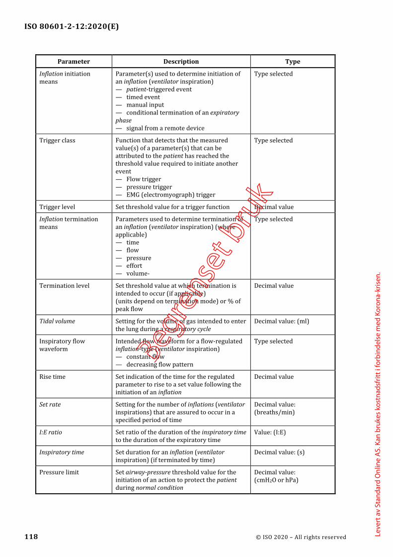
ISO 80601-2-12:2020(E)
118 © ISO 2020 – All rights reserved
Parameter Description Type
Inflation initiation means
Parameter(s) used to determine initiation of an inflation (ventilator inspiration) — patient-triggered event — timed event — manual input — conditional termination of an expiratory phase — signal from a remote device
Type selected
Trigger class Function that detects that the measured value(s) of a parameter(s) that can be attributed to the patient has reached the threshold value required to initiate another event — Flow trigger — pressure trigger — EMG (electromyograph) trigger
Type selected
Trigger level Set threshold value for a trigger function Decimal value
Inflation termination means
Parameters used to determine termination of an inflation (ventilator inspiration) (where applicable) — time — flow — pressure — effort — volume-
Type selected
Termination level Set threshold value at which termination is intended to occur (if applicable) (units depend on termination mode) or % of peak flow
Decimal value
Tidal volume Setting for the volume of gas intended to enter the lung during a respiratory cycle
Decimal value: (ml)
Inspiratory flow waveform
Intended flow waveform for a flow-regulated inflation-type (ventilator inspiration) — constant flow — decreasing flow pattern
Type selected
Rise time Set indication of the time for the regulated parameter to rise to a set value following the initiation of an inflation
Decimal value
Set rate Setting for the number of inflations (ventilator inspirations) that are assured to occur in a specified period of time
Decimal value: (breaths/min)
I:E ratio Set ratio of the duration of the inspiratory time to the duration of the expiratory time
Value: (I:E)
Inspiratory time Set duration for an inflation (ventilator inspiration) (if terminated by time)
Decimal value: (s)
Pressure limit Set airway-pressure threshold value for the initiation of an action to protect the patient during normal condition
Decimal value: (cmH2O or hPa)
Begre
nset
bru
k
Leve
rt a
v St
anda
rd O
nlin
e A
S. K
an b
ruke
s ko
stna
dsfr
itt i
forb
inde
lse
med
Kor
ona-
kris
en.

ISO 80601-2-12:2020(E)
© ISO 2020 – All rights reserved 119
Parameter Description Type
Volume limit Setting used to determine the maximum tidal volume that can be provided during an inflation (ventilator inspiration)
Decimal value (ml)
Sigh Activation of sigh function Function selected: (yes/ no)
Sigh period Set duration for a sigh inflation (if terminated by time)
Decimal value: (s)
Sigh frequency Set initiation frequency for a sigh inflation Decimal value: (breaths/min)
Apnoea limit Duration of patient apnoea after which an inflation, of a predetermined type, is provided
Decimal value: (s)
Apnoea frequency Set frequency at which preset inflations are provided during periods of patient apnoea
Decimal value: (breaths/min)
Apnoea volume The set volume intended to be delivered in a inflation (ventilator inspiration) during apnoea ventilation (if applicable)
Decimal value: (ml)
Apnoea Δ inspiratory pressure
Setting of the airway pressure, as a difference above baseline airway pressure, during an apnoea inflation (ventilator inspiration) (if applicable)
Decimal value: (cmH2O or hPa)
Oxygen concentration Set fraction of oxygen in the delivered gas Decimal value: (%)
Oxygen measurement Activation of O2 monitoring Function selected: (yes/ no)
Expired volume measurement
Activation of expired volume monitoring (if applicable)
Function selected: (yes/ no)
Expired CO2 measurement
Activation of expired CO2 monitoring (if applicable)
Function selected: (yes/ no)
Begre
nset
bru
k
Leve
rt a
v St
anda
rd O
nlin
e A
S. K
an b
ruke
s ko
stna
dsfr
itt i
forb
inde
lse
med
Kor
ona-
kris
en.

ISO 80601-2-12:2020(E)
120 © ISO 2020 – All rights reserved
Table BB.105 defines the indicators relating to monitoring of patient ventilation.
Table BB.105 — Ventilation monitoring
Parameter Description Type
Peak inspiratory pressure
Highest airway pressure reached during a previous respiratory cycle
Decimal value: (cmH2O or hPa)
PEEP Measured expiratory pressure at the end of an expiratory phase
Decimal value: (cmH2O or hPa)
Mean airway pressure Mean airway pressure over a full respiratory cycle
Decimal value: (cmH2O or hPa)
O2 Fraction of oxygen in the delivered gas Decimal value: (% O2 V/V)
Inspiratory volume Volume of gas delivered through the patient-connection port during an inflation
Decimal value: (ml)
Expired volume Volume of gas leaving the lungs through the patient-connection port during an expiratory phase
Decimal value: (ml)
End tidal CO2 End-expiratory level of CO2 leaving the lungs through the patient-connection port during an expiratory phase
Decimal value: (kPa or mmHg)
Inspiratory minute volume
Volume of gas passing through the patient-connection port during inspiratory or inflation phases, expressed as a volume per minute
Decimal value: (l/min)
Expired minute volume Volume of gas leaving the lungs through the patient-connection port during expiratory phases, expressed as a volume per minute
Decimal value: (l/min)
Assured inflation-type rate
Number of inflations (ventilator inspirations) initiated in a specified time, expressed as breaths per minute
Decimal value: (breaths/min)
Spontaneous breath rate Number of spontaneous breaths initiated in specified time, expressed as breaths per minute
Decimal value: (breaths/min)
Total respiratory rate
Number of respiratory cycles initiated in a specified time, expressed as breaths per minute (spontaneous breaths plus ventilator inflations)
Decimal value: (breaths/min)
Low respiratory rate Lowest rate of ventilatory breathing cycles delivered by the ventilator
Decimal value: (cycles/min)
I:E ratio Ratio of the duration of the inspiratory time to the duration of the expiratory time
Value: (I:E)
Total leakage Loss of respiratory gas from the VBS and the patient during the respiratory cycle
Value: (ml/min or %)
Begre
nset
bru
k
Leve
rt a
v St
anda
rd O
nlin
e A
S. K
an b
ruke
s ko
stna
dsfr
itt i
forb
inde
lse
med
Kor
ona-
kris
en.

ISO 80601-2-12:2020(E)
© ISO 2020 – All rights reserved 121
Table BB.106 defines the applicable current alarm limits of the ventilator.
Table BB.106 — Ventilator alarm limits
Parameter Description Type
High airway pressure alarm condition
Setting of the alarm limit for high pressure during the respiratory cycle
Value: (cmH2O or hPa)
High FiO2 alarm condition Setting of the alarm limit for high inspiratory oxygen concentration
Value: (% O2 V/V)
Low FiO2 alarm condition Setting of the alarm limit for low inspiratory oxygen concentration
Value: (% O2 V/V)
High end-expiratory CO2 alarm condition
Setting of the alarm limit for high end-expiratory CO2 concentration
Value: (% CO2 V/V)
Low end-expiratory CO2 alarm condition
Setting of the alarm limit for low end-expiratory CO2 concentration
Value: (% CO2 V/V)
High inspiratory tidal volume alarm condition
Setting of the alarm limit for high inspiratory tidal volume delivered by the ventilator
Value: (ml)
Low inspiratory tidal volume alarm condition
Setting of the alarm limit for low inspiratory tidal volume delivered by the ventilator
Value: (ml)
High expiratory tidal volume alarm condition
Setting of the alarm limit for high expiratory tidal volume
Value: (ml)
Low expiratory tidal volume alarm condition
Setting of the alarm limit for low expiratory tidal volume
Value: (ml)
High inspiratory minute volume alarm condition
Setting of the alarm limit for high inspiratory minute volume delivered by the ventilator
Value: (ml/min or l/min)
Low inspiratory minute volume alarm condition
Setting of the alarm limit for low inspiratory minute volume delivered by the ventilator
Value: (ml/min or l/min)
High expiratory minute volume alarm condition
Setting of the alarm limit for high expiratory minute volume
Value: (ml/min or l/min)
Low expiratory minute volume alarm condition
Setting of the alarm limit for low expiratory minute volume
Value: (ml/min or l/min)
High respiratory rate alarm condition
Setting of the alarm limit for high rate of respiratory breathing cycles delivered by the ventilator
Value: (breaths/min)
Low respiratory rate alarm condition
Setting of the alarm limit for low rate of respiratory breathing cycles delivered by the ventilator
Value: (breaths/min)
Leak alarm condition Setting of the alarm limit for high unintentional leak
Value: (l/min or %)
Begre
nset
bru
k
Leve
rt a
v St
anda
rd O
nlin
e A
S. K
an b
ruke
s ko
stna
dsfr
itt i
forb
inde
lse
med
Kor
ona-
kris
en.

ISO 80601-2-12:2020(E)
122 © ISO 2020 – All rights reserved
Table BB.107 defines applicable ventilator usage information.
Table BB.107 — Event information
Parameter Description Type
Power supply source Current source of electrical power — external AC supply mains — internal electrical power source — external DC supply mains
Type in use
Alarm signal inactive state present
List of text strings (alarm off, alarm pause, audio off, audio pause, acknowledged)
List of text strings
Active alarm condition Currently active alarm conditions List of text strings (manufacturer-defined)
Access mode Current access mode of the ventilator — supervising clinician or the healthcare professional operator — responsible organization
Type in use
Table BB.108 defines applicable service and maintenance parameters.
Table BB.108 —Service monitoring
Parameter Description Type
Maintenance needed A manufacturer-specific list of any items requiring maintenance, e.g. mask, tubing, filter
List of text strings (manufacturer-defined)
Ventilator service indicator
An indication that service is required Text string: (manufacturer-defined)
Hours of ventilation Number of hours the equipment is powered on and providing ventilation
Value: (h)
Hours until next scheduled maintenance
The next manufacturer-specified suggested maintenance interval
Value: (h)
Begre
nset
bru
k
Leve
rt a
v St
anda
rd O
nlin
e A
S. K
an b
ruke
s ko
stna
dsfr
itt i
forb
inde
lse
med
Kor
ona-
kris
en.

ISO 80601-2-12:2020(E)
© ISO 2020 – All rights reserved 123
Annex CC (informative)
Reference to the essential principles
This document has been prepared to support the essential principles of safety and performance of a ventilator, its accessories or parts as medical devices according to ISO 16142-1:2016. This document is intended to be acceptable for conformity assessment purposes.
Conformance with this document provides one means of demonstrating conformance with the specific essential principles of ISO 16142-1:2016. Other means are possible. Table CC.1 maps the clauses and subclauses of this document with the essential principles of ISO 16142-1:2016.
Table CC.1 — Correspondence between this document and the essential principles
Essential principle of ISO 16142-1:2016, Annex B
Corresponding clause(s)/sub-clause(s) of this document
Qualifying remarks/Notes
1 All The part relating to manufacturing is not addressed.
a) 206
b) 206
2 201.4 The part relating to manufacturing is not addressed.
a) All
b) 201.4 The part relating to manufacturing is not addressed.
c) 201.7, 201.11, 201.12, 201.13, 208
d) 201.7
3 All The part relating to manufacturing is not addressed.
4 All
5 201.4, 201.15
6 201.4
8.1 201.11
a) 201.11
b) 201.4, 201.11
c) 201.9, 201.15
8.2 201.11
8.3 201.11
8.4 201.11
8.5 201.11
9.1 201.11, 201.13.2.101 c)
9.8 201.7.2.17.101 b)
Begre
nset
bru
k
Leve
rt a
v St
anda
rd O
nlin
e A
S. K
an b
ruke
s ko
stna
dsfr
itt i
forb
inde
lse
med
Kor
ona-
kris
en.

ISO 80601-2-12:2020(E)
124 © ISO 2020 – All rights reserved
Essential principle of ISO 16142-1:2016, Annex B
Corresponding clause(s)/sub-clause(s) of this document
Qualifying remarks/Notes
12.1 201.7, 201.14, 201.16, 201.101, 201.102
12.2 —
a) 201.9, 201.11, 206, 208
b) 206, 208
c) 202
d) 201.11
e) 201.11
f) 201.14, 201.16, 201.105
g) 201.11, 202
12.4 201.11
12.5 201.7, 201.8
12.6 201.1.3
13.1 201.12.1, 201.102
13.2 201.7, 201.12.1
13.3 201.7, 201.12.4, 201.102, 206, 208
13.4 201.7.4.3
14.1 201.10
14.3 201.10
15.1 201.14
15.2 201.14
16.1 201.4, 201.13
16.3 201.11.8.101
16.4 201.11.8.101, 201.12.4, 201.13.101, 208
16.5 202
16.6 202
16.7 201.8
17.1 201.9
17.2 201.9
17.3 201.9
17.4 201.15
17.5 201.9, 201.101
17.6 201.11
18.1 201.12.1
18.2 201.12.4
19.1 201.7, 201.102, 206
19.2 201.7, 201.102, 206
Begre
nset
bru
k
Leve
rt a
v St
anda
rd O
nlin
e A
S. K
an b
ruke
s ko
stna
dsfr
itt i
forb
inde
lse
med
Kor
ona-
kris
en.

ISO 80601-2-12:2020(E)
© ISO 2020 – All rights reserved 125
Essential principle of ISO 16142-1:2016, Annex B
Corresponding clause(s)/sub-clause(s) of this document
Qualifying remarks/Notes
21.1 201.7
21.2 201.7
21.3 201.7
21.4 201.7
21.5 —
a) 201.7 The part relating to authorized representative is not addressed
b) 201.7.2.17.101 a) 1)
d) 201.7.2.17.101 a) 2)
e) 201.7
f) 201.7.2.17.101 b)
i) 201.7.2.101 a) 1)
j) 201.7.2.101 a) 1)
k) 201.7.2.101 a) 2)
l) 201.7
21.6 201.7, 201.7.2.17.101 a) 2)
21.7 —
a) 201.7.9.1
b) 201.7
d) 201.7.2.17.101 b), 201.7.9.2.1.101 a)
g) 201.7.9.2.9.101 f)
i) 201.7.9.2.2.101
k) 201.7.9.2.8.101, 201.7.9.2.9.101, 201.7.9.2.14.101, 201.16, 201.102.2
l) 201.7.9.2.8.101, 201.7.9.2.9.101
n) 201.16
p) 201.7.9.2.12, 201.11
q) 201.7
21.8 201.7
Begre
nset
bru
k
Leve
rt a
v St
anda
rd O
nlin
e A
S. K
an b
ruke
s ko
stna
dsfr
itt i
forb
inde
lse
med
Kor
ona-
kris
en.

ISO 80601-2-12:2020(E)
126 © ISO 2020 – All rights reserved
Annex DD (informative)
Reference to the general safety and performance requirements
This document has been prepared to support the general safety and performance requirements of regulation (EU) 2017/745[55]. This document is intended to be acceptable for conformity assessment purposes.
Conformance with this document provides one means of demonstrating conformance with the specific general safety and performance requirements of regulation (EU) 2017/745[55]. Other means are possible. Table DD.1 maps the clauses and subclauses of this document with the general safety and performance requirements of regulation (EU) 2017/745.
Where a reference from a clause or subclause of this document to the risk management process is made, the risk management process shall be such that risks have to be ‘reduced as far as possible’, ‘reduced to the lowest possible level’, ‘reduced as far as possible and appropriate’, ‘removed or reduced as far as possible’, ‘eliminated or reduced as far as possible’, ’removed or minimized as far as possible’, or ‘minimized’, according to the wording of the corresponding general safety and performance requirement.
NOTE When a general safety and performance requirement does not appear in Table DD.1, it means that it is not addressed by this document.
Table DD.1 — Correspondence between this document and the general safety and performance requirements
General safety and performance requirements of
regulation (EU) 2017/745, Annex I[55]
Corresponding clause(s)/sub-clause(s) of this document Qualifying remarks/Notes
5 a) 201.12.1, 206
5 b) 206
10.1 201.7.2.13.101, 201.11.6.6, 201.11.7 Only the part relating to design is addressed.
10.2 201.11.6.6, 201.11.7 Only the part relating to design is addressed.
10.3 201.11.6.6, 201.11.7 Only the part relating to design is addressed.
10.4 201.11.7, 201.101.2.2, 201.102.6 Only the part relating to design is addressed.
10.5 201.11 Only the part relating to design is addressed.
10.6 201.11.7, 201.101.2.2, 201.102.6 Only the part relating to design is addressed.
11.1 b) 201.11.6.6 Only the part relating to design is addressed.
11.1 c) 201.11.6.6, 201.11.6.7
11.1 d) 201.101.2.2
11.2 201.11.6.6
11.7 201.7.2.17.101
14.1
201.7.2.4.101, 201.7.2.13.101, 201.7.9.2.14.101, 201.16.1.101. 201.101, 201.101.2, 201.12.4.101, 201.12.4.104
Begre
nset
bru
k
Leve
rt a
v St
anda
rd O
nlin
e A
S. K
an b
ruke
s ko
stna
dsfr
itt i
forb
inde
lse
med
Kor
ona-
kris
en.

ISO 80601-2-12:2020(E)
© ISO 2020 – All rights reserved 127
General safety and performance requirements of
regulation (EU) 2017/745, Annex I[55]
Corresponding clause(s)/sub-clause(s) of this document Qualifying remarks/Notes
14.2 a) 201.9, 201.12.1, 201.12.4, 206 Only the part relating to design is addressed.
14.2 b) 202 Only the part relating to design is addressed.
14.2 f) 202 Only the part relating to design is addressed.
14.3 201.11 Only the part relating to design is addressed.
14.5 201.7.2.4.101, 201.7.9.2.14.101, , 201.7.9.3.1.101, 201.12.4.101, 201.12.4.104, 201.16.1.101, 201.101, 201.102
14.6 201.12.1
15.1 201.12.1.101, 201.12.2.102, 201.12.1.103 The part relating to stability is not addressed.
17.1 201.14.101
17.2 201.14.101
18.1 201.13
18.2 201.11.8.101.1
18.3 201.11.8.101.1
18.4 201.12.4
18.5 202
18.6 202
18.7 201.9.6.2.1.101
20.3 201.9.6.2.1.101 Only the part relating to design is addressed.
20.5 201.101.3, 201.101.3.2.4 Only the part relating to design is addressed.
20.6 201.11.1.2.2
21.1 201.12.1, 201.12.1.101, 201.12.1.102, 201.12.1.103
Only the protection of the patient is covered.
21.2 201.12.4.105, 201.12.4.106, 201.12.4.107, 201.12.4.108, 201.12.4.109, 201.12.101, 201.13
Only the first sentence is covered.
21.3 201.7.1.2, 201.12.1, 206
23.1 201.7, 201.7.2.101, 201.7.9.2.1.101, 201.7.9.2.2.101
The part relating to the website is not addressed.
23.1 a) 201.7.9.2.1.101, 206
23.1 b) 201.7.2.101
23.1 g) 201.7.9.2.1.101, 201.7.9.2.2.101
23.1 h)
201.7.3, 201.7.2.13.101, 201.7.2.17.101, 201.11.7
23.2 b) 201.7.2.17.101 a) 1) The part relating to intended purpose is not addressed.
23.2 c) 201.7.9.1
23.2 d) 201.7.9.1
Begre
nset
bru
k
Leve
rt a
v St
anda
rd O
nlin
e A
S. K
an b
ruke
s ko
stna
dsfr
itt i
forb
inde
lse
med
Kor
ona-
kris
en.

ISO 80601-2-12:2020(E)
128 © ISO 2020 – All rights reserved
General safety and performance requirements of
regulation (EU) 2017/745, Annex I[55]
Corresponding clause(s)/sub-clause(s) of this document Qualifying remarks/Notes
23.2 g) 201.7.2.17.101 a) 2)
23.2 k) 201.7.2.101 a) 1)
23.2 m) 201.7.2.3, 201.7.2.13.101, 201.7.2.101, 201.7.9.2.2.101
23.4 a) 201.7.9.1
23.4 e) 201.7.9.2.9.101
23.4 f) 201.7.9.2.9.101, 201.7.9.2.14.101
23.4 g) 201.7.9.2.2.101
23.4 h) 201.7.9.2.8.101, 201.7.9.2.9.101
23.4 k) 201.7.9.2.8.101
23.4 n) 201.4.4, 201.7.9.2.12, 201.11.6.6, 201.104
23.4 q) 201.7.9.2.8.101, 201.7.9.2.14.101
23.4 s) 201.7.9.2.2.101, 201.7.9.2.2.101, 201.7.9.2.8.101, 201.7.9.2.9.101, 201.11.7,
23.4 v) 201.7.9.2.12 The part relating to the website is not addressed.
Begre
nset
bru
k
Leve
rt a
v St
anda
rd O
nlin
e A
S. K
an b
ruke
s ko
stna
dsfr
itt i
forb
inde
lse
med
Kor
ona-
kris
en.

ISO 80601-2-12:2020(E)
© ISO 2020 – All rights reserved 129
Annex EE (informative)
Terminology — Alphabetized index of defined terms
NOTE The ISO Online Browsing Platform (OBP) and the IEC Electropedia (see 201.3) provide access to many of these terms and definitions.
Term Source
accessory IEC 60601-1:2005, 3.3
accompanying document IEC 60601-1:2005, 3.4
acknowledged IEC 60601-1-8:2006+AMD1:2012, 3.37
airway pressure (Paw) ISO 19223:2019, 3.6.1
alarm condition IEC 60601-1-8:2006+AMD1:2012, 3.1
alarm condition delay IEC 60601-1-8:2006, 3.2
alarm limit IEC 60601-1-8:2006, 3.3
alarm off IEC 60601-1-8:2006, 3.4
alarm paused IEC 60601-1-8:2006, 3.5
alarm settings IEC 60601-1-8:2006, 3.8
alarm signal IEC 60601-1-8:2006, 3.9
alarm system IEC 60601-1-8:2006, 3.11
applied part IEC 60601-1:2005, 3.8
assured inflation-type rate ISO 19223:2019, 3.5.2.1
audio off IEC 60601-1-8:2006, 3.12
audio paused IEC 60601-1-8:2006, 3.13
BAP ISO 19223:2019, 3.10.2
basic safety IEC 60601-1:2005, 3.10
bias flow ISO 19223:2019, 3.7.7
biocompatibility ISO 18562-1:2017, 3.3
breathing system filter ISO 23328-2:2002, 3.1
BSF ISO 23328-2:2002, 3.1
BTPS IEC 80601-2-74:2017, 201.3.203
cleaning ISO 17664:2017, 3.1
clearly legible IEC 60601-1:2005+AMD1:2012, 3.15
continuous flow ISO 19223:2019, 3.7.8
continuous operation IEC 60601-1:2005, 3.18
continuous positive airway pressure ISO 19223:2019, 3.11.15
CPAP ISO 19223:2019, 3.11.15
Δ inspiratory pressure ISO 19223:2019, 3.6.7
disinfection ISO 17664:2017, 3.3
Begre
nset
bru
k
Leve
rt a
v St
anda
rd O
nlin
e A
S. K
an b
ruke
s ko
stna
dsfr
itt i
forb
inde
lse
med
Kor
ona-
kris
en.
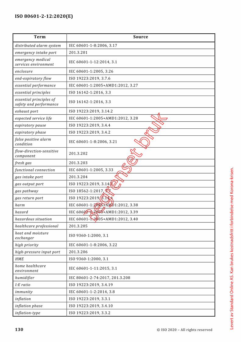
ISO 80601-2-12:2020(E)
130 © ISO 2020 – All rights reserved
Term Source
distributed alarm system IEC 60601-1-8:2006, 3.17
emergency intake port 201.3.201
emergency medical services environment IEC 60601-1-12:2014, 3.1
enclosure IEC 60601-1:2005, 3.26
end-expiratory flow ISO 19223:2019, 3.7.6
essential performance IEC 60601-1:2005+AMD1:2012, 3.27
essential principles ISO 16142-1:2016, 3.3
essential principles of safety and performance ISO 16142-1:2016, 3.3
exhaust port ISO 19223:2019, 3.14.2
expected service life IEC 60601-1:2005+AMD1:2012, 3.28
expiratory pause ISO 19223:2019, 3.4.4
expiratory phase ISO 19223:2019, 3.4.2
false positive alarm condition IEC 60601-1-8:2006, 3.21
flow-direction-sensitive component 201.3.202
fresh gas 201.3.203
functional connection IEC 60601-1:2005, 3.33
gas intake port 201.3.204
gas output port ISO 19223:2019, 3.14.3
gas pathway ISO 18562-1:2017, 3.7
gas return port ISO 19223:2019, 3.14.4
harm IEC 60601-1:2005+AMD1:2012, 3.38
hazard IEC 60601-1:2005+AMD1:2012, 3.39
hazardous situation IEC 60601-1:2005+AMD1:2012, 3.40
healthcare professional 201.3.205
heat and moisture exchanger ISO 9360-1:2000, 3.1
high priority IEC 60601-1-8:2006, 3.22
high-pressure input port 201.3.206
HME ISO 9360-1:2000, 3.1
home healthcare environment IEC 60601-1-11:2015, 3.1
humidifier IEC 80601-2-74:2017, 201.3.208
I:E ratio ISO 19223:2019, 3.4.19
immunity IEC 60601-1-2:2014, 3.8
inflation ISO 19223:2019, 3.3.1
inflation phase ISO 19223:2019, 3.4.10
inflation-type ISO 19223:2019, 3.3.2
Begre
nset
bru
k
Leve
rt a
v St
anda
rd O
nlin
e A
S. K
an b
ruke
s ko
stna
dsfr
itt i
forb
inde
lse
med
Kor
ona-
kris
en.

ISO 80601-2-12:2020(E)
© ISO 2020 – All rights reserved 131
Term Source
information signal IEC 60601-1-8:2006, 3.23
inspiratory pause ISO 19223:2019, 3.4.12
inspiratory time (tI) ISO 19223:2019, 3.4.8
inspiratory volume (Vinsp) ISO 19223:2019, 3.8.3
intended use IEC 60601-1:2005+AMD1:2012, 3.44
intelligent alarm system IEC 60601-1-8:2006, 3.24
internal electrical power source IEC 60601-1:2005, 3.45
latching alarm signal IEC 60601-1-8:2006, 3.26
low priority IEC 60601-1-8:2006, 3.27
manufacturer IEC 60601-1:2005+AMD1:2012, 3.55
mask ISO 17510:2015, 3.4
maximum limited pressure (PLIM max) ISO 19223:2019, 3.13.3
maximum working pressure (PW max) ISO 19223:2019, 3.13.4
ME equipment IEC 60601-1:2005, 3.63
ME system IEC 60601-1:2005, 3.64
mechanical hazard IEC 60601-1:2005, 3.61
medical electrical equipment IEC 60601-1:2005, 3.63
medical electrical system IEC 60601-1:2005, 3.64
medical gas pipeline system ISO 7396-1:2016, 3.36
medium priority IEC 60601-1-8:2006, 3.28
minimum limited pressure (PLIM min) 201.3.207
model or type reference IEC 60601-1:2005, 3.66
monitoring equipment 201.3.208
nominal <value> IEC 60601-1:2005, 3.69
normal condition IEC 60601-1:2005, 3.70
normal use IEC 60601-1:2005, 3.71
operator IEC 60601-1:2005, 3.73
operator-equipment interface IEC 60601-1-6:2010, 3.1
operator's position IEC 60601-1-8:2006, 3.30
patient IEC 60601-1:2005+AMD1:2012, 3.76
patient-connection port ISO 19223:2019, 3.14.5
PEEP ISO 19223:2019, 3.10.4
PEMS IEC 60601-1:2005, 3.90
Begre
nset
bru
k
Leve
rt a
v St
anda
rd O
nlin
e A
S. K
an b
ruke
s ko
stna
dsfr
itt i
forb
inde
lse
med
Kor
ona-
kris
en.

ISO 80601-2-12:2020(E)
132 © ISO 2020 – All rights reserved
Term Source
PESS IEC 60601-1:2005, 3.91
physiologic closed-loop control system IEC 60601-1-10:2007, 3.19
positive end-expiratory pressure ISO 19223:2019, 3.10.4
pressure-control ISO 19223:2019, 3.3.4
primary operating function IEC 62366-1:2015, 3.11
procedure IEC 60601-1:2005+AMD1:2012, 3.88
process IEC 60601-1:2005+AMD1:2012, 3.89
processing ISO 17664:2017, 3.8
professional healthcare facility 201.3.209
programmable electrical medical systems IEC 60601-1:2005, 3.90
programmable electronic subsystem IEC 60601-1:2005, 3.91
protection device 201.3.210
rated <value> IEC 60601-1:2005, 3.97
residual risk IEC 60601-1:2005+AMD1:2012, 3.100
respiratory cycle ISO 19223:2019, 3.4.16
responsible organization IEC 60601-1:2005, 3.101
risk IEC 60601-1:2005+AMD1:2012, 3.102
risk control IEC 60601-1:2005+AMD1:2012, 3.105
risk management IEC 60601-1:2005+AMD1:2012, 3.107
risk management file IEC 60601-1:2005+AMD1:2012, 3.108
safety sign ISO 7010:2019, 3.3
service personnel IEC 60601-1:2005, 3.113
set rate ISO 19223:2019, 3.5.1.1
single fault condition IEC 60601-1:2005+AMD1:2012, 3.116
single fault safe IEC 60601-1:2005, 3.117
software item IEC 62304:2006+AMD1:2015, 3.25
spontaneous breath rate ISO 19223:2019, 3.5.1.3
stationary IEC 60601-1:2005+AMD1:2012, 3.118
sterilization ISO 17664:2017, 3.17
STPD IEC 80601-2-74:2017, 201.3.220
suction catheter ISO 8836:2014, 3.22
supply mains IEC 60601-1:2005, 3.120
technical alarm condition IEC 60601-1-8:2006, 3.36
tidal volume (Vtidal) ISO 19223:2019, 3.8.1
tool IEC 60601-1:2005, 3.127
Begre
nset
bru
k
Leve
rt a
v St
anda
rd O
nlin
e A
S. K
an b
ruke
s ko
stna
dsfr
itt i
forb
inde
lse
med
Kor
ona-
kris
en.

ISO 80601-2-12:2020(E)
© ISO 2020 – All rights reserved 133
Term Source
total respiratory rate ISO 19223:2019, 3.5.1.2
transit-operable IEC 60601-1-11:2015, 3.4
type test IEC 60601-1:2005, 3.135
usability IEC 62366-1:2015, 3.16
usability engineering IEC 62366-1:2015, 3.17
usability engineering file IEC 62366-1:2015, 3.18
validated ISO 9000:2015, 3.8.13
VBS ISO 19223:2019, 3.1.18
ventilator ISO 19223:2019, 3.1.1
ventilator breathing system ISO 19223:2019, 3.1.18
ventilator operational-mode ISO 19223:2019, 3.11.1
ventilation-mode ISO 19223:2019, 3.11.2
ventilator-dependent 201.3.211
verified IEC 60601-1:2005+AMD1:2012, 3.138
volume-control ISO 19223:2019, 3.3.3
Begre
nset
bru
k
Leve
rt a
v St
anda
rd O
nlin
e A
S. K
an b
ruke
s ko
stna
dsfr
itt i
forb
inde
lse
med
Kor
ona-
kris
en.

ISO 80601-2-12:2020(E)
134 © ISO 2020 – All rights reserved
Bibliography
[1] ISO 639-1:2002, Codes for the representation of names of languages — Part 1: Alpha-2 Code
[2] ISO 80601-2-13, Medical electrical equipment — Part 2-13: Particular requirements for basic safety and essential performance of an anaesthetic workstation
[3] ISO 80601-2-84:— 2, Medical Electrical Equipment — Part 2-84: Particular requirements for basic safety and essential performance of emergency and transport ventilators
[4] ISO 10651-3, Lung ventilators for medical use — Part 3: Particular requirements for emergency and transport ventilators
[5] ISO 80601-2-72:2015, Medical electrical equipment — Part 2-72: Particular requirements for basic safety and essential performance of home healthcare environment ventilators for ventilator-dependent patients
[6] ISO 80601-2-79:2018, Medical electrical equipment — Part 2-79: Particular requirements for basic safety and essential performance of ventilatory support equipment for ventilatory impairment
[7] ISO 80601-2-80:2018, Medical electrical equipment — Part 2-80: Particular requirements for basic safety and essential performance of ventilatory support equipment for ventilatory insufficiency
[8] ISO 15001:2010, Anaesthetic and respiratory equipment — Compatibility with oxygen
[9] ISO 80601-2-70, Medical electrical equipment — Part 2-70: Particular requirements for basic safety and essential performance of sleep apnoea breathing therapy equipment
[10] ISO 32:1977, Gas cylinders for medical use — Marking for identification of content
[11] FROESE, A.B., (2006) High-Frequency Ventilation. In: Principles and Practice of Mechanical Ventilation, Second edition; (ed. Tobin, M.J., MD), McGraw-Hill, New York. pp. 473-492. ISBN 0873894286
[12] IEC 60601-1-3, Medical electrical equipment — Part 1-3: General requirements for basic safety and essential performance — Collateral Standard: Radiation protection in diagnostic X-ray equipment
[13] IEC 60601-1-9, Medical electrical equipment — Part 1-9: General requirements for basic safety and essential performance — Collateral Standard: Requirements for environmentally conscious design
[14] ISO 4135:2001 Anaesthetic and respiratory equipment — Vocabulary
2 Under preparation. Stage at the time of publication: ISO/FDIS 80601-2-84:2020.
Begre
nset
bru
k
Leve
rt a
v St
anda
rd O
nlin
e A
S. K
an b
ruke
s ko
stna
dsfr
itt i
forb
inde
lse
med
Kor
ona-
kris
en.

ISO 80601-2-12:2020(E)
© ISO 2020 – All rights reserved 135
[15] ISO 10651-4:2002, Lung ventilators — Part 4: Particular requirements for operator-powered resuscitators
[16] ISO 27427:2013, Anaesthetic and respiratory equipment — Nebulizing systems and components
[17] BURTON, G.W. and FOX, D.E.R. (1972) An airway resistance for use in an artificial lung. Brit J of Anaes, 44, pp. 1253-1262
[18] MECKLENBURGH, J.S. (1988) Construction of linear resistance units for a model lung. Med and Biol Elect and Comp, 26, pp. 552-554
[19] MUSHIN, W.W., RENDELL-BAKER, L., THOMPSON, P.W. and MAPLESON, W.W. (1980) Automatic Ventilation of the Lungs (3rd edition), pp. 182-183
[20] ISO 10079-1:2015, Medical suction equipment — Part 1: Electrically powered suction equipment
[21] ISO 10079-3:2014, Medical suction equipment — Part 3: Suction equipment powered from a vacuum or positive pressure gas source
[22] ISO 14159:2002, Safety of machinery — Hygiene requirements for the design of machinery
[23] HILL, D.W. and MOORE, V. (1965) The action of adiabatic effects on the compliance of an artificial thorax. Br J of Anaes, 37, pp. 19-22
[24] IEC/TR 60721-4-7:2001, Classification of environmental conditions — Part 4-7: Guidance for the correlation and transformation of environmental condition classes of IEC 60721-3 to the environmental tests of IEC 60068 — Portable and non-stationary use
[25] EN 15986:2011, Symbol for use in the labelling of medical devices — Requirements for labelling of medical devices containing phthalates
[26] ASTM F2761-09, Medical Devices and Medical Systems — Essential safety requirements for equipment comprising the patient-centric integrated clinical environment (ICE) — Part 1: General requirements and conceptual model
[27] IEC/TR 60878:2015, Graphical symbols for electrical equipment in medical practice
[28] ISO 8601-1:2019, Date and time — Representations for information interchange — Part 1: Basic rules
[29] ISO 10524-1:2018, Pressure regulators for use with medical gases — Part 1: Pressure regulators and pressure regulators with flow-metering devices
[30] EL MASRY, A., et al, (2005) The impact of closed endotracheal suctioning systems on mechanical ventilator performance, Respir Care, 50(3), pp. 345-53
[31] STENQVIST O., et al, (2001) Warning! Suctioning. A lung model evaluation of closed suctioning systems, Acta Anaesthesiol Scand, 45, pp. 167-172
Begre
nset
bru
k
Leve
rt a
v St
anda
rd O
nlin
e A
S. K
an b
ruke
s ko
stna
dsfr
itt i
forb
inde
lse
med
Kor
ona-
kris
en.
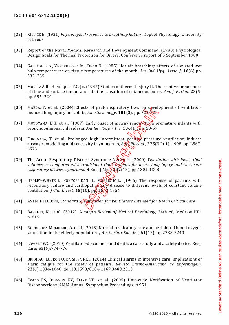
ISO 80601-2-12:2020(E)
136 © ISO 2020 – All rights reserved
[32] KILLICK E. (1931) Physiological response to breathing hot air. Dept of Physiology, University of Leeds
[33] Report of the Naval Medical Research and Development Command, (1980) Physiological Design Goals for Thermal Protection for Divers, Conference report of 5 September 1980
[34] GALLAGHER S., VERCRUYSSEN M., DENO N. (1985) Hot air breathing: effects of elevated wet bulb temperatures on tissue temperatures of the mouth. Am. Ind. Hyg. Assoc. J. 46(6) pp. 332–335
[35] MORITZ A.R., HENRIQUES F.C. JR. (1947) Studies of thermal injury II. The relative importance of time and surface temperature in the causation of cutaneous burns. Am. J. Pathol. 23(5) pp. 695–720
[36] MAEDA, Y. et al, (2004) Effects of peak inspiratory flow on development of ventilator-induced lung injury in rabbits, Anesthesiology, 101(3), pp. 722-728
[37] MOTOYAMA, E.K. et al, (1987) Early onset of airway reactivity in premature infants with bronchopulmonary dysplasia, Am Rev Respir Dis, 136(1), pp. 50-57
[38] FUKUNAGA, T, et al, Prolonged high intermittent positive-pressure ventilation induces airway remodelling and reactivity in young rats, Am.J Physiol., 275(3 Pt 1), 1998, pp. L567-L573
[39] The Acute Respiratory Distress Syndrome Network, (2000) Ventilation with lower tidal volumes as compared with traditional tidal volumes for acute lung injury and the acute respiratory distress syndrome. N Engl J Med. 342(18), pp.1301-1308
[40] HEDLEY-WHYTE J., PONTOPPIDAN H., MORRIS M.J., (1966) The response of patients with respiratory failure and cardiopulmonary disease to different levels of constant volume ventilation, J Clin Invest, 45(10), pp. 1543-1554
[41] ASTM F1100:90, Standard Specification for Ventilators Intended for Use in Critical Care
[42] BARRETT, K. et al. (2012) Ganong’s Review of Medical Physiology, 24th ed, McGraw Hill, p. 619.
[43] RODRIGUEZ-MOLINERO, A. et al, (2013) Normal respiratory rate and peripheral blood oxygen saturation in the elderly population. J Am Geriatr Soc Dec, 61(12), pp.2238-2240.
[44] LOWERY WC. (2010) Ventilator-disconnect and death: a case study and a safety device. Resp Care; 55(6):774-776
[45] BRIDI AC, LOURO TQ, DA SILVA RCL. (2014) Clinical alarms in intensive care: implications of alarm fatigue for the safety of patients. Revista Latino-Americana de Enfermagem. 22(6):1034-1040. doi:10.1590/0104-1169.3488.2513
[46] EVANS RS, JOHNSON KV, FLINT VB, et al. (2005) Unit-wide Notification of Ventilator Disconnections. AMIA Annual Symposium Proceedings. p.951
Begre
nset
bru
k
Leve
rt a
v St
anda
rd O
nlin
e A
S. K
an b
ruke
s ko
stna
dsfr
itt i
forb
inde
lse
med
Kor
ona-
kris
en.
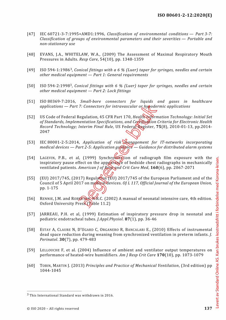
ISO 80601-2-12:2020(E)
© ISO 2020 – All rights reserved 137
[47] IEC 60721-3-7:1995+AMD1:1996, Classification of environmental conditions — Part 3-7: Classification of groups of environmental parameters and their severities — Portable and non-stationary use
[48] EVANS, J.A., WHITELAW, W.A., (2009) The Assessment of Maximal Respiratory Mouth Pressures in Adults. Resp Care, 54(10), pp. 1348-1359
[49] ISO 594-1:19863, Conical fittings with a 6 % (Luer) taper for syringes, needles and certain other medical equipment — Part 1: General requirements
[50] ISO 594-2:19983, Conical fittings with 6 % (Luer) taper for syringes, needles and certain other medical equipment — Part 2: Lock fittings
[51] ISO 80369-7:2016, Small-bore connectors for liquids and gases in healthcare applications — Part 7: Connectors for intravascular or hypodermic applications
[52] US Code of Federal Regulation, 45 CFR Part 170, Health Information Technology: Initial Set of Standards, Implementation Specifications, and Certification Criteria for Electronic Health Record Technology; Interim Final Rule, US Federal Register, 75(8), 2010-01-13, pp.2014-2047
[53] IEC 80001-2-5:2014, Application of risk management for IT-networks incorporating medical devices — Part 2-5: Application guidance — Guidance for distributed alarm systems
[54] LAGEVIN, P.B., et al, (1999) Synchronization of radiograph film exposure with the inspiratory pause effect on the appearance of bedside chest radiographs in mechanically ventilated patients. American J of Resp and Crit Care Med, 160(6), pp. 2067-2071
[55] (EU) 2017/745, (2017) Regulation (EU) 2017/745 of the European Parliament and of the Council of 5 April 2017 on medical devices. OJ L 117, Official Journal of the European Union, pp. 1-175
[56] RENNIE, J.M. and ROBERTON, N.R.C. (2002) A manual of neonatal intensive care, 4th edition. Oxford University Press (Table 11.2)
[57] JARREAU, P.H. et al, (1999) Estimation of inspiratory pressure drop in neonatal and pediatric endotracheal tubes. J.Appl.Physiol. 87(1), pp. 36-46
[58] ESTAY A, CLAURE N, D'UGARD C, ORGANERO R, BANCALARI E., (2010) Effects of instrumental dead space reduction during weaning from synchronized ventilation in preterm infants. J. Perinatol. 30(7), pp. 479-483
[59] LELLOUCHE F, et al. (2004) Influence of ambient and ventilator output temperatures on performance of heated-wire humidifiers. Am J Resp Crit Care 170(10), pp. 1073-1079
[60] TOBIN, MARTIN J. (2013) Principles and Practice of Mechanical Ventilation, (3rd edition) pp 1044-1045
3 This International Standard was withdrawn in 2016.
Begre
nset
bru
k
Leve
rt a
v St
anda
rd O
nlin
e A
S. K
an b
ruke
s ko
stna
dsfr
itt i
forb
inde
lse
med
Kor
ona-
kris
en.
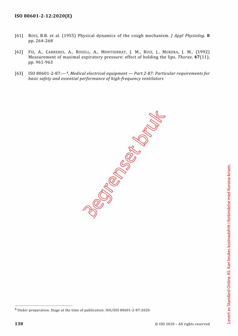
ISO 80601-2-12:2020(E)
138 © ISO 2020 – All rights reserved
[61] ROSS, B.B. et al. (1955) Physical dynamics of the cough mechanism. J Appl Physiolog. 8 pp. 264-268
[62] FIZ, A., CARRERES, A., ROSELL, A., MONTSERRAT, J. M., RUIZ, J., MORERA, J. M., (1992) Measurement of maximal expiratory pressure: effect of holding the lips. Thorax. 47(11), pp. 961-963
[63] ISO 80601-2-87:—4, Medical electrical equipment — Part 2-87: Particular requirements for basic safety and essential performance of high-frequency ventilators
4 Under preparation. Stage at the time of publication: ISO/DIS 80601-2-87:2020.
Begre
nset
bru
k
Leve
rt a
v St
anda
rd O
nlin
e A
S. K
an b
ruke
s ko
stna
dsfr
itt i
forb
inde
lse
med
Kor
ona-
kris
en.

Begre
nset
bru
k
Leve
rt a
v St
anda
rd O
nlin
e A
S. K
an b
ruke
s ko
stna
dsfr
itt i
forb
inde
lse
med
Kor
ona-
kris
en.

ISO 80601-2-12:2020(E)
© ISO 2020 – All rights reserved
ICS 11.040.10Price based on 138 pages
Begre
nset
bru
k
Leve
rt a
v St
anda
rd O
nlin
e A
S. K
an b
ruke
s ko
stna
dsfr
itt i
forb
inde
lse
med
Kor
ona-
kris
en.