8 - Electrical Equipment
295
© Renault s.a.s 2008 "The repair methods given by the manufacturer in this document are based on the technical specifications current when it was prepared. The methods may be modified as a result of changes introduced by the manufacturer in the production of the various component units and accessories from which his vehicles are constructed." All copyrights reserved by Renault. The reproduction or translation in part of whole of the present document, as well as the use of the spare parts reference numbering system, are prohibited without the prior written consent of Renault. JUNE 2008 Edition Anglaise X95 8 Electrical equipment 80A BATTERY 80B HEADLIGHTS 81A REAR LIGHTING 81B INTERIOR LIGHTING 81C FUSES 82A ENGINE IMMOBILISER 82B HORN 82C ALARM 83A INSTRUMENT PANEL 83C ON-BOARD TELEMA TICS SYSTEM 83D CRUISE CONTROL
-
Upload
hugo-mendes -
Category
Documents
-
view
224 -
download
0
Transcript of 8 - Electrical Equipment

8/6/2019 8 - Electrical Equipment
http://slidepdf.com/reader/full/8-electrical-equipment 1/294
© Renault s.a.s 2008
"The repair methods given by the manufacturer in this document are based on the technical
specifications current when it was prepared.
The methods may be modified as a result of changes introduced by the manufacturer in theproduction of the various component units and accessories from which his vehicles areconstructed."
All copyrights reserved by Renault.
The reproduction or translation in part of whole of the present document, as well as the useof the spare parts reference numbering system, are prohibited without the prior writtenconsent of Renault.
JUNE 2008 Edition Anglaise
X95
8 Electrical equipment
80A BATTERY
80B HEADLIGHTS
81A REAR LIGHTING
81B INTERIOR LIGHTING
81C FUSES
82A ENGINE IMMOBILISER
82B HORN
82C ALARM
83A INSTRUMENT PANEL
83C ON-BOARD TELEMATICS SYSTEM
83D CRUISE CONTROL

8/6/2019 8 - Electrical Equipment
http://slidepdf.com/reader/full/8-electrical-equipment 2/294
© Renault s.a.s 2008
"The repair methods given by the manufacturer in this document are based on the technical
specifications current when it was prepared.
The methods may be modified as a result of changes introduced by the manufacturer in theproduction of the various component units and accessories from which his vehicles areconstructed."
All copyrights reserved by Renault.
The reproduction or translation in part of whole of the present document, as well as the useof the spare parts reference numbering system, are prohibited without the prior writtenconsent of Renault.
JUNE 2008 Edition Anglaise
X95
84A CONTROL - SIGNALS
85A WIPING - WASHING
86A RADIO
86B CAR PHONE
87BPASSENGER COMPARTMENT CONNECTIONUNIT
87C OPENING ELEMENT MANAGEMENT
87D ELECTRIC WINDOWS - SUNROOF
87F PARKING DISTANCE CONTROL
87G ENGINE COMPARTMENT CONNECTION UNIT
88A WIRING HARNESS
88C AIR BAG AND PRETENSIONERS
88D DRIVER'S POSITION

8/6/2019 8 - Electrical Equipment
http://slidepdf.com/reader/full/8-electrical-equipment 3/294
MEGANE III - Section 8
Contents
Page
MEGANE III- Section 8ContentsPage
80A BATTERY
Battery: Precautions forrepair 80A-1
Battery : Removal - Refitting 80A-2
Battery disconnection unit:Removal - Refitting 80A-5
Battery tray: Removal -Refitting 80A-8
Battery terminals: Removal -Refitting 80A-12
80B HEADLIGHTS
Front lighting: List andlocation of components 80B-1
Front headlight: Removal -Refitting 80B-4
Front headlight: Adjusting 80B-6
Headlight bulb: Removal -Refitting 80B-8
Front fog light bulb: Removal- Refitting 80B-18
Front fog light: Removal -Refitting 80B-19
Side indicator: Removal -Refitting 80B-20
Headlight adjustment frontsensor: Removal - Refitting 80B-21
Headlight adjustment rearsensor: Removal - Refitting 80B-23
Xenon headlight high voltageunit: Removal - Refitting 80B-25
Front lighting computer:Removal - Refitting 80B-26
81A REAR LIGHTING
Rear lighting: List andlocation of components 81A-1
Rear light on wing: Removal- Refitting 81A-5
Rear opening element light:Removal - Refitting 81A-7
Rear light bulb: Removal -Refitting 81A-8
Third brake light: Removal -Refitting 81A-11
Rear fog light bulb: Removal- Refitting 81A-14
Rear fog lights: Removal -Refitting 81A-15
Number plate light: Removal- Refitting 81A-16
81B INTERIOR LIGHTING
Interior lights: List andlocation of components 81B-1
Courtesy light: Removal -Refitting 81B-3
Lower door light: Removal -Refitting 81B-5
80B HEADLIGHTS

8/6/2019 8 - Electrical Equipment
http://slidepdf.com/reader/full/8-electrical-equipment 4/294
Contents
Vanity light: Removal -Refitting 81B-6
Glovebox light: Removal -Refitting 81B-7
Luggage compartment light:Removal - Refitting 81B-8
81C FUSES
Fuses: List and location of
components 81C-1
82A ENGINE IMMOBILISER
Immobiliser system: List andlocation of components 82A-1
Start button: Removal -Refitting 82A-3
Steering column electric
lock: Removal - Refitting 82A-4
Card reader: Removal -Refitting 82A-6
Starting aerial: Removal -Refitting 82A-7
Remote door locking controlbattery: Removal - Refitting 82A-9
82B HORN
Horn: Removal - Refitting 82B-1
82C ALARM
Alarm: List and location ofcomponents 82C-1
81B INTERIOR LIGHTING 83A INSTRUMENT PANEL
Instrument panel: Removal -Refitting 83A-1
83C ON-BOARD TELEMATICS SYSTEM
Navigation: List and locationof components 83C-1
Radio navigation system:Removal - Refitting 83C-3
Navigation computer:
Removal - Refitting 83C-5
Multimedia network interfaceunit: Removal - Refitting 83C-7
Central control: Removal -Refitting 83C-9
Navigation screen: Removal- Refitting 83C-10
83D CRUISE CONTROL
Cruise control / speed limiter:List and location ofcomponents 83D-1
Switch: Removal - Refitting 83D-4
84A CONTROL - SIGNALS
Under steering wheel controlassembly: List and locationof components 84A-1
Steering wheel controlsassembly: Removal -Refitting 84A-4
Hazard warning lights switchand central locking: Removal- Refitting 84A-7
ESP inhibitor switch:Removal - Refitting 84A-8

8/6/2019 8 - Electrical Equipment
http://slidepdf.com/reader/full/8-electrical-equipment 5/294
Contents
Remote headlightadjustment control: Removal
- Refitting 84A-10
Lighting dimmer: Removal -Refitting 84A-12
Door mirror control switch:Removal - Refitting 84A-14
Heated seat cover switch:Removal - Refitting 84A-15
85A WIPING - WASHING
Wipers and washer: List andlocation of components 85A-1
Windscreen wiper blade:Removal - Refitting 85A-6
Windscreen wiper arm:Removal - Refitting 85A-7
Windscreen wipermechanism: Removal -
Refitting 85A-8
Rear screen wiper blade:Removal - Refitting 85A-10
Rear screen wiper arm:Removal - Refitting 85A-12
Rear screen wiper motor:Removal - Refitting 85A-14
Rain and light sensor:Removal - Refitting 85A-15
Windscreen washer pump:Removal - Refitting 85A-19
Headlight washer pump:Removal - Refitting 85A-20
Windscreen washer jet:Removal - Refitting 85A-22
Rear screen washer jet:Removal - Refitting 85A-23
84A CONTROL - SIGNALS
Windscreen washer bottle:Removal - Refitting 85A-24
Windscreen washer bottlefunnel: Removal - Refitting 85A-26
86A RADIO
Audio equipment: List andlocation of components 86A-1
Car radio: Removal -
Refitting 86A-6
Tuner-amplifier: Removal -Refitting 86A-8
Radio aerial: Removal -Refitting 86A-10
Radio aerial amplifier:Removal - Refitting 86A-11
Tweeter: Removal - Refitting 86A-12
Front speakers: Removal -
Refitting 86A-14
Rear speakers: Removal -Refitting 86A-15
Display: Removal - Refitting 86A-17
Radio control satellite:Removal - Refitting 86A-18
Offset multimedia socket:Removal - Refitting 86A-19
Offset multimedia socket
computer: Removal -Refitting 86A-20
86B CAR PHONE
Hands-free microphone:Removal - Refitting 86B-1
85A WIPING - WASHING

8/6/2019 8 - Electrical Equipment
http://slidepdf.com/reader/full/8-electrical-equipment 6/294
Contents
87BPASSENGER COMPARTMENTCONNECTION UNIT
UCH: Removal - Refitting 87B-1
87C OPENING ELEMENT MANAGEMENT
Door management: List andlocation of components 87C-1
Opening aerial: Removal -Refitting 87C-4
Tailgate opening switch:Removal - Refitting 87C-5
Remote central door lockingwarning: Removal - Refitting 87C-6
Lock motor for the fuel fillingcompartment: Removal -Refitting 87C-7
87D ELECTRIC WINDOWS - SUNROOF
Electric window: List and
location of components 87D-1
Electric sunroof: List andlocation of components 87D-3
Front electric windowswitches on driver's doorRemoval - Refitting 87D-4
Front electric window switchon the passenger door:Removal - Refitting 87D-6
Rear electric window switch:Removal - Refitting 87D-8
Child safety switch: Removal- Refitting 87D-9
Window winder motor:Removal - Refitting 87D-10
Sunroof switch: Removal -Refitting 87D-12
Electric sunroof computer:Removal - Refitting 87D-14
Sunroof opening motorRemoval - Refitting 87D-15
87F PARKING DISTANCE CONTROL
Parking proximity sensor:List and location ofcomponents 87F-1
Parking proximity sensorswitch: Removal - Refitting 87F-4
Parking proximity sensorbuzzer: Removal - Refitting 87F-6
Proximity radar Removal -Refitting 87F-8
Parking proximity sensorcomputer: Removal -Refitting 87F-11
87GENGINE COMPARTMENT CONNECTIONUNIT
Protection and SwitchingUnit: Removal - Refitting 87G-1
88A WIRING HARNESS
Computers List and location
of components 88A-1
Diagnostic socket: List andlocation of components 88A-3
Wiring: Precautions for repair 88A-4
Front bumper wiring:Connector opening 88A-5
Front bumper wiring:Removal - Refitting 88A-7
Driver's front side door
wiring: Removal - Refitting 88A-11
87D ELECTRIC WINDOWS - SUNROOF

8/6/2019 8 - Electrical Equipment
http://slidepdf.com/reader/full/8-electrical-equipment 7/294
Contents
Passenger's front side doorwiring: Removal - Refitting 88A-14
Rear right-hand side doorwiring: Removal - Refitting 88A-17
Rear left-hand side doorwiring: Removal - Refitting 88A-20
Rear bumper wiring:Connector opening 88A-23
Rear bumper wiring:Removal - Refitting 88A-25
88C AIR BAG AND PRETENSIONERS
Airbag and Pretensioners:List and location ofcomponents 88C-1
Airbag and Pretensioners:Precautions for repair 88C-7
Airbags and pretensioners:Recycling - Destruction 88C-9
Airbag computer: Removal -Refitting 88C-11
Driver's front airbag:Removal - Refitting 88C-14
Passenger front airbag:Removal - Refitting 88C-17
Front (chest) side airbag:Removal - Refitting 88C-19
Side curtain airbag: Removal
- Refitting 88C-22
Side impact sensor: Removal- Refitting 88C-26
Anti-submarining airbag:Removal - Refitting 88C-30
Inhibitor switch: Removal -Refitting 88C-32
Front seat lap beltpretensioner: Removal -Refitting 88C-33
88A WIRING HARNESS
Front seat belt buckle:Removal - Refitting 88C-35
Rear seat belt buckle:Removal - Refitting 88C-36
Front side seat belt: Removal- Refitting 88C-39
Rear side seat belt: Removal- Refitting 88C-46
Rear centre seat belt:Removal - Refitting 88C-52
Seat belt reminder warning
light: Removal - Refitting 88C-54
88D DRIVER'S POSITION
Electrical accessoriessocket: Removal - Refitting 88D-1
Cigarette lighter: Removal -Refitting 88D-2
88C AIR BAG AND PRETENSIONERS

8/6/2019 8 - Electrical Equipment
http://slidepdf.com/reader/full/8-electrical-equipment 8/29480A-1
BATTERY
Battery: Precautions for repair 80AI - SAFETY
1 - DANGER: RISK FROM ACID LINKED TOHANDLING
Sulphuric acid is a highly aggressive and toxic subs-tance which corrodes most metals.
When handling batteries, it is very important to take thefollowing precautions:
- protect your eyes by wearing goggles,
- wear acid-proof gloves and clothing.
2 - DANGER: RISK OF EXPLOSION LINKED TOCHARGING AND TO INCORRECT TIGHTENING OFTHE TERMINALS.
When a battery is charging, oxygen and hydrogen areproduced. The mixture of these two gases is explosive.
The smallest of sparks or heat sources can cause anexplosion. The explosion is so strong that the batterycan shatter and spray the acid into the surrounding at-mosphere.
People nearby are at risk (exploded fragments, acidsplashes). Acid splashes are dangerous. They also da-mage clothing.
Safeguarding against the danger of explosion, whichcan be caused by handling a battery carelessly, mustbe taken very seriously.
II - CLEANLINESS
Check that the battery terminals are clean (see Batte-ry: Check) (Technical Note 6002A, 80A, Battery).
III - GENERAL RECOMMENDATIONS
IMPORTANT
A battery contains sulphuric acid, a dangeroussubstance.
If acid splashes on to your clothing, rinse all conta-minated areas thoroughly in water.
If it comes into contact with the skin or eyes, seekmedical attention.
IMPORTANT
To prevent damaging the battery or even causing itto explode, do not place any heat sources or createany sparks near a charging battery.
WARNING
Incorrect tightening could cause heating of con-tacts, starting or charging faults, sparking, or could
cause the battery to explode.
IMPORTANT
To avoid all risk of sparks, ensure that all electricalconsumers are fully switched off.
When a battery is being charged inside a building,switch off the charger before connecting or discon-necting the battery.
Do not place any metallic items on the battery asthis may create a short circuit across the terminals.
Never hold a naked flame, welding gun, blowtorch,cigarette or lighted match near to a battery.
WARNING
These vehicles are equipped with a battery with lowwater consumption. Topping up the electrolyte istherefore prohibited.
WARNING
Before disconnecting the battery:
- wait for the motor-driven fan assembly to stop,
- wait for the computer to finish saving (1 minute).
WARNING
Some vehicles are only fitted with « TB » (low hei-
ght) batteries. To avoid damaging the bonnet, onlyrefit a battery which is identical to the battery origi-nally fitted.

8/6/2019 8 - Electrical Equipment
http://slidepdf.com/reader/full/8-electrical-equipment 9/29480A-2
BATTERY
Battery : Removal - Refitting 80A
REMOVAL
I - REMOVAL PREPARATION OPERATION
a Switch off the ignition.a Unclip the battery cover at (1) .
II - OPERATION FOR REMOVAL OF PARTCONCERNED
1 - Disconnection
a Remove:
- the negative battery terminal nuts (2) ,
- the wiring of the negative battery terminal.
a Unclip the wiring at (3) .
a Move aside the negative battery terminal wiring.
Tightening torquesm
battery bracket bolts 8 N.m
positive wiring nuts 8 N.m
negative wiring nuts 8 N.m
IMPORTANT
To avoid all risk of damage to the systems, applythe safety and cleanliness instructions and opera-tion recommendations before carrying out anyrepair (see 80A, Battery, Battery: Precautions forrepair, page 80A-1) .
WARNING
Before disconnecting the battery:
- wait for the motor-driven fan assembly to stop,
- wait for the computer to finish saving (1minute).
WARNING
The visual indicator cannot be considered relia-ble in After-Sales; do not use it to determine thestate of the battery.
137318
137319

8/6/2019 8 - Electrical Equipment
http://slidepdf.com/reader/full/8-electrical-equipment 10/29480A-3
BATTERY
Battery : Removal - Refitting 80A
a Remove:
- the positive battery terminal nut (4) ,
- the wiring of the positive battery terminal.
a Remove:
- the nut (5) of the battery disconnection unit wiring,
- the positive battery terminal wiring on the batterydisconnection unit,
- the positive battery terminal wiring.
2 - Removal
a Remove:
- the battery bracket bolts (6) ,
- the battery bracket.
a Remove the battery.
3 - Replacement
a Remove the battery connectors (see 80A, Battery,
Battery terminals: Removal - Refitting, page 80A-12) .
REFITTING
I - REFITTING PREPARATION OPERATION
a Check the battery (see Battery: Check) (TechnicalNote 6002A, 80A, Battery).
II - REFITTING OPERATION FOR PARTCONCERNED
1 - Replacement
a Refit the battery terminals (see 80A, Battery, Batte-ry terminals: Removal - Refitting, page 80A-12) .
137320
137321
137322
Note:
Do not remove the cover of the injection compu-ter.
8/6/2019 8 - Electrical Equipment
http://slidepdf.com/reader/full/8-electrical-equipment 11/29480A-4
BATTERY
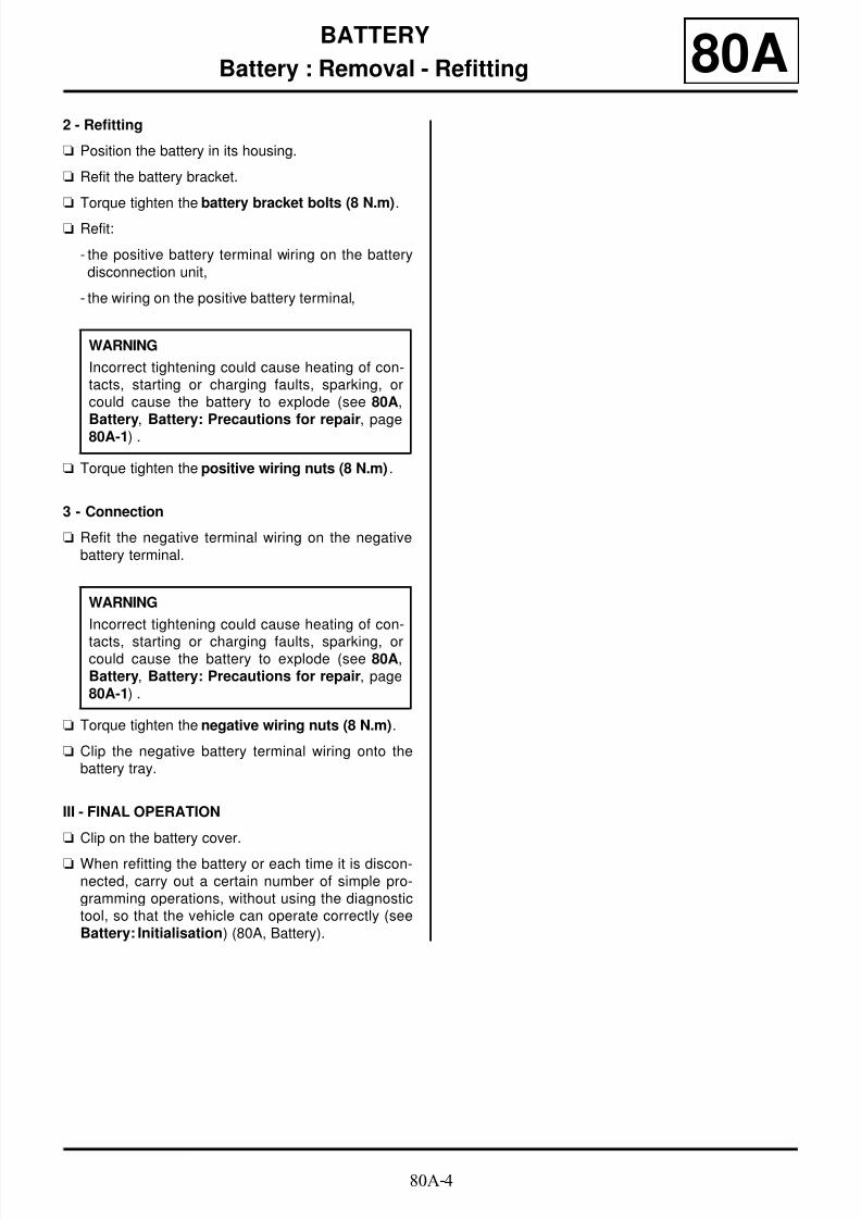
Battery : Removal - Refitting 80A2 - Refitting
a Position the battery in its housing.
a Refit the battery bracket.
a Torque tighten the battery bracket bolts (8 N.m).
a Refit:
- the positive battery terminal wiring on the batterydisconnection unit,
- the wiring on the positive battery terminal,
a Torque tighten the positive wiring nuts (8 N.m) .
3 - Connection
a Refit the negative terminal wiring on the negativebattery terminal.
a Torque tighten the negative wiring nuts (8 N.m).
a Clip the negative battery terminal wiring onto thebattery tray.
III - FINAL OPERATION
a Clip on the battery cover.
a When refitting the battery or each time it is discon-nected, carry out a certain number of simple pro-gramming operations, without using the diagnostictool, so that the vehicle can operate correctly (seeBattery: Initialisation) (80A, Battery).
WARNING
Incorrect tightening could cause heating of con-tacts, starting or charging faults, sparking, orcould cause the battery to explode (see 80A,
Battery, Battery: Precautions for repair, page80A-1) .
WARNING
Incorrect tightening could cause heating of con-
tacts, starting or charging faults, sparking, orcould cause the battery to explode (see 80A,Battery, Battery: Precautions for repair, page80A-1) .
8/6/2019 8 - Electrical Equipment
http://slidepdf.com/reader/full/8-electrical-equipment 12/29480A-5
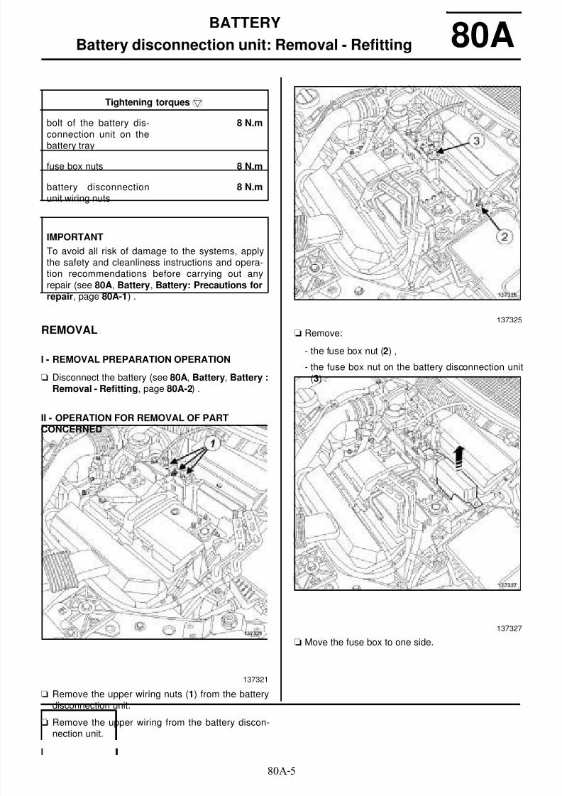
BATTERY
Battery disconnection unit: Removal - Refitting 80A
REMOVAL
I - REMOVAL PREPARATION OPERATION
a Disconnect the battery (see 80A, Battery, Battery :Removal - Refitting, page 80A-2) .
II - OPERATION FOR REMOVAL OF PARTCONCERNED
aRemove the upper wiring nuts (1) from the batterydisconnection unit.
a Remove the upper wiring from the battery discon-nection unit.
a Remove:
- the fuse box nut (2) ,
- the fuse box nut on the battery disconnection unit(3) .
a Move the fuse box to one side.
Tightening torquesm
bolt of the battery dis-
connection unit on thebattery tray
8 N.m
fuse box nuts 8 N.m
battery disconnectionunit wiring nuts
8 N.m
IMPORTANT
To avoid all risk of damage to the systems, applythe safety and cleanliness instructions and opera-tion recommendations before carrying out anyrepair (see 80A, Battery, Battery: Precautions forrepair, page 80A-1) .
137321
137325
137327

8/6/2019 8 - Electrical Equipment
http://slidepdf.com/reader/full/8-electrical-equipment 13/29480A-6
BATTERY
Battery disconnection unit: Removal - Refitting 80A
a Remove the bolt from the disconnection unit (4) .
a Partially remove the battery disconnection unitupwards (5) .
a Unclip the safety devices of the lower connectors (6)
.
a Disconnect the lower and side connectors from thebattery disconnection unit (7) .
a Remove the battery disconnection unit.
REFITTING
I - REFITTING OPERATION FOR PARTCONCERNED
a Connect the lower and side connectors of the dis-connection unit.
137328
137329
137330
137331

8/6/2019 8 - Electrical Equipment
http://slidepdf.com/reader/full/8-electrical-equipment 14/29480A-7
BATTERY
Battery disconnection unit: Removal - Refitting 80Aa Refit the battery disconnection unit.
a Torque tighten the bolt of the battery disconnec-tion unit on the battery tray (8 N.m).
a Refit the fuse box.
a Torque tighten the fuse box nuts (8 N.m).
a Refit the battery disconnection unit wiring.
a Torque tighten the battery disconnection unit wi-ring nuts (8 N.m).
II - FINAL OPERATION
a Connect the battery (see 80A, Battery, Battery :Removal - Refitting, page 80A-2) .
WARNING
Incorrect tightening could cause heating of con-tacts, starting or charging faults, sparking, orcould cause the battery to explode (see 80A,Battery, Battery: Precautions for repair, page80A-1) .
WARNING
Incorrect tightening could cause heating of con-tacts, starting or charging faults, sparking, orcould cause the battery to explode (see 80A,Battery, Battery: Precautions for repair, page80A-1) .

8/6/2019 8 - Electrical Equipment
http://slidepdf.com/reader/full/8-electrical-equipment 15/29480A-8
BATTERY
Battery tray: Removal - Refitting 80A
REMOVAL
I - REMOVAL PREPARATION OPERATION
a Remove:
- the battery (see 80A, Battery, Battery : Removal- Refitting, page 80A-2) ,
- the battery disconnection unit (see 80A, Battery,Battery disconnection unit: Removal - Refitting,page 80A-5) .
a Remove:
- the air duct (1) from the injection computer,
- the injection computer cover (2) .
a Disconnect the injection computer connectors (3) .
a Remove the injection computer support bolts (4) .
a Extract the "support - injection computer" assemblyupwards.
a Remove the "support - injection computer" assem-bly.
Tightening torquesm
battery tray bolts 21 N.m
IMPORTANT
To avoid all risk of damage to the systems, applythe safety and cleanliness instructions and opera-tion recommendations before carrying out anyrepair (see 80A, Battery, Battery: Precautions forrepair, page 80A-1) .
136455
136463
136462

8/6/2019 8 - Electrical Equipment
http://slidepdf.com/reader/full/8-electrical-equipment 16/29480A-9
BATTERY
Battery tray: Removal - Refitting 80AII - OPERATION FOR REMOVAL OF PARTCONCERNED
a Remove the bolt (5) .
a Move the "solenoid valve - support" assembly (6)away from the battery tray.
a Unclip the wiring from the battery tray at (7) .
a Remove the Protection and Switching Unit supportbolts (8) .
137336
137334
137335

8/6/2019 8 - Electrical Equipment
http://slidepdf.com/reader/full/8-electrical-equipment 17/29480A-10
BATTERY
Battery tray: Removal - Refitting 80A
a Remove the bolts (9) from the battery tray.
a Move aside the battery tray.
a Unclip:
- the wiring at (10) ,
- the drain duct (11) .
a Remove the battery tray.
a Unclip the battery acid drain pipe.
REFITTING
I - REFITTING OPERATION FOR PARTCONCERNED
a Clip on the battery acid drain pipe.
a Refit the battery tray.
a Clip on the drain duct.
a Pretighten the bolt (3) .
a Torque tighten in order the battery tray bolts (21N.m).
a Refit the bolt (12) .
a Clip the wiring onto the battery tray.
a Refit:
- the Protection and Switching Unit support bolts,
- the "solenoid valve - support" assembly on the bat-tery tray,
- the solenoid valve support bolt.
II - FINAL OPERATION
a Connect the injection computer connectors.
a Refit:
- the "support - injection computer" assembly,
- the injection computer support bolts,
- the injection computer cover,
- the air duct of the injection computer,
137337
137338
137337

8/6/2019 8 - Electrical Equipment
http://slidepdf.com/reader/full/8-electrical-equipment 18/29480A-11
BATTERY
Battery tray: Removal - Refitting 80A- the battery disconnection unit (see 80A, Battery,Battery disconnection unit: Removal - Refitting,page 80A-5) ,
- the battery (see 80A, Battery, Battery : Removal- Refitting, page 80A-2) .

8/6/2019 8 - Electrical Equipment
http://slidepdf.com/reader/full/8-electrical-equipment 19/29480A-12
BATTERY
Battery terminals: Removal - Refitting 80A
REMOVAL
I - REMOVAL PREPARATION OPERATION
a Switch off the ignition.
a Disconnect the battery (see 80A, Battery, Battery :Removal - Refitting, page 80A-2) .
a Remove the battery disconnection unit wiring fromthe positive battery terminal.
II - OPERATION FOR REMOVAL OF PARTCONCERNED
a Undo the positive battery terminal (1) .
a Remove the positive battery terminal.
a Undo the negative battery terminal (2) .
a Remove the negative battery terminal.
REFITTING
I - REFITTING OPERATION FOR PARTCONCERNED
a Push the connectors fully onto the battery terminals.
a Refit:
- the positive terminal on the battery,
- the negative terminal on the battery.
a Tighten to torque:
- the positive terminal on the battery (8 N.m) ,
Tightening torquesm
positive terminal on the
battery
8 N.m
negative terminal on thebattery
8 N.m
nut of the battery dis-connection unit wiringon the positive batteryterminal
8 N.m
IMPORTANT
To avoid all risk of damage to the systems, applythe safety and cleanliness instructions and opera-tion recommendations before carrying out anyrepair (see 80A, Battery, Battery: Precautions forrepair, page 80A-1) .
WARNING
Before disconnecting the battery:
- wait for the motor-driven fan assembly to stop,
- wait for the computer to finish saving (1minute).
WARNING
The visual indicator cannot be considered relia-
ble in After-Sales; do not use it to determine thestate of the battery.
137324
WARNING
To avoid any damage to the wiring, observe thecorrect orientation of the battery terminal.
WARNING
Incorrect tightening could cause heating of con-tacts, starting or charging faults, sparking, orcould cause the battery to explode (see 80A,
Battery, Battery: Precautions for repair, page
80A-1) .

8/6/2019 8 - Electrical Equipment
http://slidepdf.com/reader/full/8-electrical-equipment 20/29480A-13
BATTERY
Battery terminals: Removal - Refitting 80A-the negative terminal on the battery (8 N.m).
II - FINAL OPERATION
a Refit the battery disconnection unit wiring on the po-
sitive battery terminal.
a Torque tighten the nut of the battery disconnec-tion unit wiring on the positive battery terminal(8 N.m).
a Connect the battery (see 80A, Battery, Battery :Removal - Refitting, page 80A-2) .
WARNING
Incorrect tightening could cause heating of con-tacts, starting or charging faults, sparking, orcould cause the battery to explode (see 80A,Battery, Battery: Precautions for repair, page80A-1) .

8/6/2019 8 - Electrical Equipment
http://slidepdf.com/reader/full/8-electrical-equipment 21/29480B-1
HEADLIGHTS
Front lighting: List and location of components
B95 or D95 or E95 or K95
80B
I - LIST OF COMPONENTS
The front lighting consists of:
- headlights- halogen bulbs
- side direction indicators
- front fog lights
- front fog lights bulbs
- xenon bulbs
- a headlight beam adjustment front sensor
- a headlight beam adjustment rear sensor
- xenon headlights high voltage units
- a front lighting computer
II - LOCATION OF COMPONENTS
Headlights
Halogen bulbs
Halogen bulb (dipped beam headlight)
FOG LIGHT
XENON BULBS
135394
135388
(1) Direction indicator bulb
(2) Daytime running light bulb
(3) Main beam headlight bulbs
(4) Side light bulbs
WITHOUT XENON BULBS
135365

8/6/2019 8 - Electrical Equipment
http://slidepdf.com/reader/full/8-electrical-equipment 22/29480B-2
HEADLIGHTS
Front lighting: List and location of components
B95 or D95 or E95 or K95
80B
Side indicator
Front fog light
Front fog light bulb
Xenon bulb (dipped beam headlight)
135395
FOG LIGHT
135394
135346
XENON BULBS
135396

8/6/2019 8 - Electrical Equipment
http://slidepdf.com/reader/full/8-electrical-equipment 23/29480B-3
HEADLIGHTS
Front lighting: List and location of components
B95 or D95 or E95 or K95
80B
Headlight adjustment front sensor
Headlight adjustment rear sensor
Xenon headlight high voltage unit
Front lighting computer
The front lighting computer is located behind the pas-senger compartment fuse and relay box regardless ofthe driver's position.
135404
135402
135386
135342

8/6/2019 8 - Electrical Equipment
http://slidepdf.com/reader/full/8-electrical-equipment 24/29480B-4
HEADLIGHTS
Front headlight: Removal - Refitting
B95 or D95 or E95 or K95
80B
REMOVAL
I - REMOVAL PREPARATION OPERATION
aPosition the vehicle on a two-post lift (see Vehicle:Towing and lifting) (02A, Lifting equipment).
a Switch off the ignition.
a
a Disconnect the battery (see 80A, Battery, Battery :Removal - Refitting, page 80A-2) .
a Remove the front bumper (see Front bumper: Re-moval - Refitting) (55A, Exterior protection).
II - OPERATION FOR REMOVAL OF PARTCONCERNED
a Remove:
- the headlight upper bolts (1) ,
- the collet.
aMove the headlight towards the front of the vehicle(2) .
a Disconnect the headlight connectors.
a Remove the headlight.
When replacing the headlight
a Remove the headlight bulbs (see 80B, Headlights,Headlight bulb: Removal - Refitting, page 80B-8).
a Remove the xenon headlight high voltage unit (see80B, Headlights, Xenon headlight high voltageunit: Removal - Refitting, page 80B-25) .
XENON BULBS
IMPORTANT
To prevent eye injuries:
- do not look at a discharge bulb when lit (voltage
when lit 20000 V),
- do not light a bulb which has not been fitted intoits headlight.
IMPORTANT
To prevent burns, wait until the « computers -power unit » assemblies are cold before removal.
135389
XENON BULBS

8/6/2019 8 - Electrical Equipment
http://slidepdf.com/reader/full/8-electrical-equipment 25/29480B-5
HEADLIGHTS
Front headlight: Removal - Refitting
B95 or D95 or E95 or K95
80B
REFITTING
I - REFITTING OPERATION FOR PARTCONCERNED
When replacing the headlight
a Refit the headlight bulbs (see 80B, Headlights,
Headlight bulb: Removal - Refitting, page 80B-8).
a Refit the xenon headlight high voltage unit (see 80B,
Headlights, Xenon headlight high voltage unit:Removal - Refitting, page 80B-25) .
a Connect the headlight connectors.
a Refit:
- the headlight,
- the collet,
- the front bumper (see Front bumper: Removal -Refitting) (55A, Exterior protection).
II - FINAL OPERATION
a Connect the battery (see 80A, Battery, Battery :Removal - Refitting, page 80A-2) .
a Adjust the headlight beam (see 80B, Headlights,
Front headlight: Adjusting, page 80B-6) .
XENON BULBS
XENON BULBS

8/6/2019 8 - Electrical Equipment
http://slidepdf.com/reader/full/8-electrical-equipment 26/294

8/6/2019 8 - Electrical Equipment
http://slidepdf.com/reader/full/8-electrical-equipment 27/29480B-7
HEADLIGHTS
Front headlight: Adjusting
B95 or D95 or E95 or K95
80B
a Adjust the headlight beam using the headlight ad-justment and checking tool and by turning the bolt(1) .
2 - Horizontal adjustment
a Use the headlight adjustment and checking toolto horizontally adjust the headlight by turning the bolt(2) .
a Position a small ratchet fitted with an 8 mm socket toaccess the horizontal adjustment bolt (2) .
IV - FINAL OPERATION
a Close the bonnet.
WITHOUT XENON BULBS
135391
Note:
A setting recess is provided for beam adjust-ment.
135393

8/6/2019 8 - Electrical Equipment
http://slidepdf.com/reader/full/8-electrical-equipment 28/29480B-8
HEADLIGHTS
Headlight bulb: Removal - Refitting
B95 or D95 or E95 or K95
80B
REMOVAL
a
I - REMOVAL PREPARATION OPERATION
a Switch off the ignition.
a Disconnect the battery (see 80A, Battery, Battery :Removal - Refitting, page 80A-2) .
a
Remove:
- the collet,
- the headlight upper bolts (1) .
a Move the headlight towards the front of the vehicleby approximately 8 cm (2) .
II - OPERATION FOR REMOVAL OF PARTCONCERNED
1 - Direction indicator bulb
aUnlock the bulb holder by turning it a quarter of aturn anti-clockwise (3) .
a Remove the direction indicator bulb from the bulbholder.
XENON BULBS
IMPORTANT
To prevent eye injuries:
- do not look at a discharge bulb when lit (voltagewhen lit 20000 V),
- do not light a bulb which has not been fitted intoits headlight.
IMPORTANT
To prevent burns, wait until the « computers -power unit » assemblies are cold before removal.
XENON BULBS
135389
135616

8/6/2019 8 - Electrical Equipment
http://slidepdf.com/reader/full/8-electrical-equipment 29/29480B-9
HEADLIGHTS
Headlight bulb: Removal - Refitting
B95 or D95 or E95 or K95
80B
2 - Daytime running light bulb
a Remove the sealing cover (4) .
a Unlock the bulb holder (5) by turning it a quarter of a
turn anti-clockwise.
a Remove:
- the bulb holder from the headlight,
- the daytime running light bulb from the bulb holder.
3 - Dipped beam headlight bulb
a Remove the sealing cover (6) .
a Remove the xenon dipped headlight bulb by pullingit towards yourself (9) .
a Disconnect the connector (7) of the xenon dippedheadlight bulb.
a Unlock the xenon dipped headlight bulb by turning ita quarter of a turn anti-clockwise (8) .
135616
135398
XENON BULBS
135616
135396

8/6/2019 8 - Electrical Equipment
http://slidepdf.com/reader/full/8-electrical-equipment 30/29480B-10
HEADLIGHTS
Headlight bulb: Removal - Refitting
B95 or D95 or E95 or K95
80B
a Remove the sealing cover (10) .
a Disconnect the connector (11) from the dippedbeam headlight bulb.
a Unlock the clip (12) from the dipped beam headlight
bulb.
a Remove the dipped beam headlight bulb.
4 - Main beam headlight bulbs
a Remove the sealing cover (13) .
a Unclip the main beam headlight bulb (15) .
a Remove the main beam headlight bulb.
a Disconnect the connector (14) from the main beamheadlight bulb.
WITHOUT XENON BULBS
135388
135365
135388
135364

8/6/2019 8 - Electrical Equipment
http://slidepdf.com/reader/full/8-electrical-equipment 31/29480B-11
HEADLIGHTS
Headlight bulb: Removal - Refitting
B95 or D95 or E95 or K95
80B
5 - Side light bulbs
a Remove the sealing cover (16) .
a Unclip:
- the bulb holder (17) from the headlight,
- the side light from the bulb holder.
REFITTING
I - REFITTING PREPARATION OPERATION
a
a
II - REFITTING OPERATION FOR PARTCONCERNED
1 - Direction indicator bulb
a Refit the indicator bulb onto the bulb holder.
a Lock the bulb holder by turning it a quarter of turnclockwise.
2 - Daytime running light bulb
a Refit:
- the daytime running light bulb on the bulb holder,
- the bulb holder on the headlight.
135388
135330
Note:
When replacing a bulb, only use approved bulbs.
XENON BULBS
116288
WARNING
To prevent any breakages, handle the bulb by its
base. If you should touch the glass, clean it withalcohol and a lint-free cloth.
WARNING
The bulb must be handled with care.
The external conductor is very fragile and mustnot be damaged.

8/6/2019 8 - Electrical Equipment
http://slidepdf.com/reader/full/8-electrical-equipment 32/29480B-12
HEADLIGHTS
Headlight bulb: Removal - Refitting
B95 or D95 or E95 or K95
80B
a Lock the bulb holder by turning it a quarter of turnclockwise.
a Refit the sealing cover.
3 - Dipped beam headlight bulb
a Connect the connector of the xenon dipped beamheadlight bulb.
a Refit the xenon dipped beam headlight bulb.
a Lock the xenon dipped beam headlight bulb by tur-ning it a quarter of a turn clockwise.
a Refit the sealing cover.
a Refit the dipped beam headlight bulb.
a Fasten the clip on the dipped beam headlight bulb.
a Connect the connector to the dipped beam headlightbulb.
a Refit the sealing cover.
4 - Main beam headlight bulbs
a Connect the connector of the main beam headlightbulb.
a Refit the main beam headlight bulb while clipping itonto its reflector.
a Refit the sealing cover.
5 - Side light bulbs
a Clip:
- the side light bulb onto the bulb holder,
- the bulb holder on the headlight.
a Refit the sealing cover.
III - FINAL OPERATION
a Refit:
- the headlight,
- the collet.
a Connect the battery (see 80A, Battery, Battery :
Removal - Refitting, page 80A-2) .
XENON BULBS
WITHOUT XENON BULBS
XENON BULBS

8/6/2019 8 - Electrical Equipment
http://slidepdf.com/reader/full/8-electrical-equipment 33/29480B-13
HEADLIGHTS
Headlight bulb: Removal - Refitting
J95
80B
REMOVAL
a
I - REMOVAL PREPARATION OPERATION
a Switch off the ignition.
a Disconnect the battery (see Battery: Removal - Re-fitting) .
For the right-hand headlight bulbs
a Remove the windscreen washer bottle neck.
II - OPERATION FOR REMOVAL OF PARTCONCERNED
1 - Direction indicator bulb
a Unlock the bulb holder by turning it a quarter of aturn anti-clockwise (1) .
a Remove the direction indicator bulb from the bulbholder.
XENON BULBS
IMPORTANT
To prevent eye injuries:
- do not look at a discharge bulb when lit (voltagewhen lit 20000 V),
- do not light a bulb which has not been fitted intoits headlight.
IMPORTANT
To prevent burns, wait until the « computers -power unit » assemblies are cold before removal.
XENON BULBS
100006-1

8/6/2019 8 - Electrical Equipment
http://slidepdf.com/reader/full/8-electrical-equipment 34/294

8/6/2019 8 - Electrical Equipment
http://slidepdf.com/reader/full/8-electrical-equipment 35/29480B-15
HEADLIGHTS
Headlight bulb: Removal - Refitting
J95
80B
4 - Main beam headlight bulbs
a Remove the sealing cover (9) .
a Unlock the bulb holder (10) by turning it a quarter ofa turn anti-clockwise.
a Remove:
- the bulb holder from the headlight,
- the dipped beam headlight bulb from the bulb hol-der.
a Disconnect the connector (11) from the main beamheadlight bulb.
a Unclip the main beam headlight bulb (12) .
5 - Side light bulbs
a Remove the sealing cover (13) .
100000-1
XENON BULBS
138414
WITHOUT XENON BULBS
100000-1
100000-1

8/6/2019 8 - Electrical Equipment
http://slidepdf.com/reader/full/8-electrical-equipment 36/29480B-16
HEADLIGHTS
Headlight bulb: Removal - Refitting
J95
80B
a Unclip:
- the bulb holder (14) from the headlight,
- the side light bulb from the bulb holder.
REFITTING
I - REFITTING PREPARATION OPERATION
a
a
II - REFITTING OPERATION FOR PARTCONCERNED
1 - Direction indicator bulb
a Refit the indicator bulb onto the bulb holder.
a Lock the bulb holder on the headlight by turning it aquarter of turn clockwise.
100000-1
Note:
When replacing a bulb, only use approved bulbs.
XENON BULBS
116288
WARNING
To prevent any breakages, handle the bulb by its
base. If you should touch the glass, clean it withalcohol and a lint-free cloth.
WARNING
The bulb must be handled with care.
The external conductor is very fragile and mustnot be damaged.

8/6/2019 8 - Electrical Equipment
http://slidepdf.com/reader/full/8-electrical-equipment 37/29480B-17
HEADLIGHTS
Headlight bulb: Removal - Refitting
J95
80B
2 - daytime running light bulb
a Refit the daytime running light bulb on the bulb hol-der.
a Lock the bulb holder on the headlight by turning it aquarter of turn clockwise.
3 - Dipped beam headlight bulb
a Refit the xenon dipped beam headlight bulb.
a Lock the xenon dipped beam headlight bulb by tur-ning the locking ring.
a Connect the connector to the dipped beam headlight
bulb.
a Refit the sealing cover.
a Clip on the dipped beam headlight bulb.
a Connect the connector to the dipped beam headlightbulb.
a Refit the sealing cover.
4 - Main beam headlight bulbs
a Refit:
- the main beam headlight bulb on the bulb holder,
- the bulb holder on the headlight.
a Lock the bulb holder by turning it a quarter of turnclockwise.
a Refit the sealing cover.
a Clip on the main beam headlight bulb.
a Connect the connector to the main beam headlightbulb.
a Refit the sealing cover.
5 - Side light bulbs
a Clip:
- the side light bulb onto the bulb holder,
- the bulb holder on the headlight.
a Refit the sealing cover.
III - FINAL OPERATION
For the right-hand headlight
a Refit the windscreen washer bottle neck.
a Connect the battery (see Battery: Removal - Refit-ting) .
WITHOUT XENON BULBS
XENON BULBS
WITHOUT XENON BULBS
XENON BULBS
WITHOUT XENON BULBS
XENON BULBS

8/6/2019 8 - Electrical Equipment
http://slidepdf.com/reader/full/8-electrical-equipment 38/29480B-18
HEADLIGHTS
Front fog light bulb: Removal - Refitting
B95 or D95 or E95 or K95, and FOG LIGHT
80B
REMOVAL
I - REMOVAL PREPARATION OPERATION
a Position the vehicle on a two-post lift (see Vehicle:Towing and lifting) (02A, Lifting equipment).
a Remove:
- the front wheels (see Wheel: Removal - Refitting)(35A, Wheels and tyres),
- the front wheel arch liners (see Front wheel archliner: Removal - Refitting) (55A, Exterior protec-tion),
- the front bumper (see Front bumper: Removal -
Refitting) (55A, Exterior protection).
II - OPERATION FOR REMOVAL OF PARTCONCERNED
a Disconnect the front fog light connector (1) .
a Remove the front fog light bulb anticlockwise (2) .
REFITTING
I - REFITTING OPERATION FOR PART
CONCERNED
a Refit the front fog light bulb clockwise.
a Connect the front fog light connector.
II - FINAL OPERATION
a Refit:
- the front bumper (see Front bumper: Removal -
Refitting) (55A, Exterior protection),- the front wheel arch liners (see Front wheel arch
liner: Removal - Refitting) (55A, Exterior protec-tion),
- the front wheels (see Wheel: Removal - Refitting)(35A, Wheels and tyres).
135346

8/6/2019 8 - Electrical Equipment
http://slidepdf.com/reader/full/8-electrical-equipment 39/29480B-19
HEADLIGHTS
Front fog light: Removal - Refitting
B95 or D95 or E95 or K95, and FOG LIGHT
80B
REMOVAL
I - REMOVAL PREPARATION OPERATION
a Position the vehicle on a two-post lift (see Vehicle:Towing and lifting) (02A, Lifting equipment).
a Remove:
- the front wheels (see Wheel: Removal - Refitting)(35A, Wheels and tyres),
- the wheel arch liners (see Front wheel arch liner:Removal - Refitting) (55A, Exterior protection),
- the front bumper (see Front bumper: Removal -
Refitting) (55A, Exterior protection).
II - OPERATION FOR REMOVAL OF PARTCONCERNED
a Disconnect the front fog light connector (1) .
a Remove:
- the bolts (2) from the front fog light,
- the front fog light.
When replacing the front fog light
a Remove the front fog light bulb (see 80B, Headli-ghts, Front fog light bulb: Removal - Refitting,page 80B-18) .
REFITTING
I - REFITTING OPERATION FOR PARTCONCERNED
When replacing the front fog light
a Refit the front fog light bulb (see 80B, Headlights,Front fog light bulb: Removal - Refitting, page80B-18) .
a Refit the front fog light.
a Connect the front fog light connector.
II - FINAL OPERATIONa Refit:
- the front bumper (see Front bumper: Removal -Refitting) (55A, Exterior protection),
- the front wheel arch liners (see Front wheel archliner: Removal - Refitting) (55A, Exterior protec-tion),
- the front wheels (see Wheel: Removal - Refitting)(35A, Wheels and tyres).
135345
8/6/2019 8 - Electrical Equipment
http://slidepdf.com/reader/full/8-electrical-equipment 40/294

8/6/2019 8 - Electrical Equipment
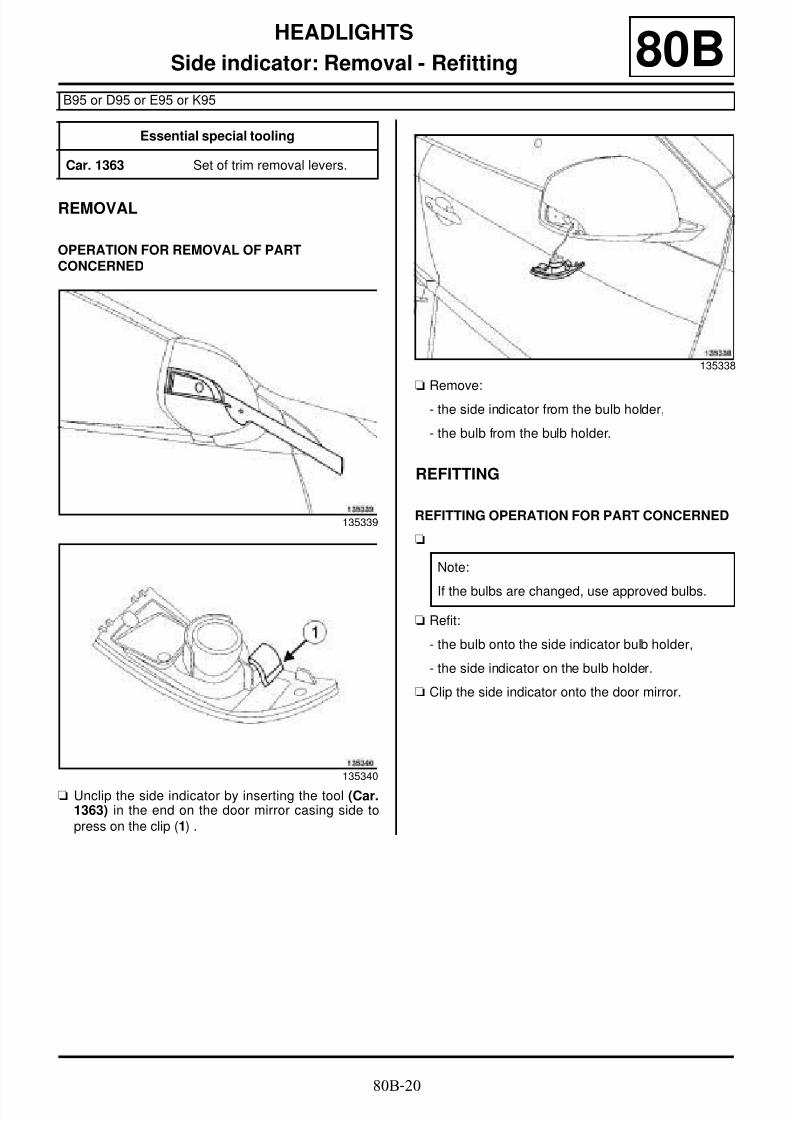
http://slidepdf.com/reader/full/8-electrical-equipment 41/29480B-21
HEADLIGHTS
Headlight adjustment front sensor: Removal - Refitting
B95 or D95 or E95 or K95, and XENON BULBS
80B
REMOVAL
I - REMOVAL PREPARATION OPERATION
a Position the vehicle on a two-post lift (see Vehicle:
Towing and lifting) (02A, Lifting equipment).
a Switch off the ignition.
a Remove the front left-hand wheel (see Wheel: Re-moval - Refitting) (35A, Wheels and tyres).
II - OPERATION FOR REMOVAL OF PART
CONCERNED
a Disconnect the headlight beam adjustment front
sensor connector (1) .
a Remove:
- the nut (2) from the mounting of the headlight beam
adjustment front sensor linkage ball joint,
- the headlight beam adjustment front sensor linkage
ball joint mounting from the front driveshaft lower
arm.
aRemove:- the bolts (3) of the headlight beam adjustment front
sensor,
- the headlight beam adjustment front sensor.
REFITTING
I - REFITTING PREPARATION OPERATION
a
a Remove the sensor from its mounting.
II - REFITTING OPERATION FOR PARTCONCERNED
a Refit:
- the headlight beam adjustment front sensor,
- the mounting of the headlight beam adjustmentfront sensor linkage ball joint.
a Connect the headlight beam adjustment front sensorconnector.
III - FINAL OPERATION
a Refit the front left-hand wheel (see Wheel: Removal- Refitting) (35A, Wheels and tyres).
a In the event of a replacement, apply the after repairprocedure using the diagnostic tool :
- connect the diagnostic tool,
- select “Headlight adjustment computer”,
- go to repair mode,
Essential equipment
diagnostic tool
135404
135403
Note:When replacing the headlight beam adjustmentfront sensor, it is sold with its mounting.

8/6/2019 8 - Electrical Equipment
http://slidepdf.com/reader/full/8-electrical-equipment 42/29480B-22
HEADLIGHTS
Headlight adjustment front sensor: Removal - Refitting
B95 or D95 or E95 or K95, and XENON BULBS
80B
- display the "Before/after repair procedure" for thecomputer selected,
- select "Headlight beam adjustment front sensor" inthe "List of components controlled by this compu-
ter" section,
- carry out the operations described in the "After re-pair procedure" section.
a Adjust the headlight beam (see 80B, Headlights,Front headlight: Adjusting, page 80B-6) .

8/6/2019 8 - Electrical Equipment
http://slidepdf.com/reader/full/8-electrical-equipment 43/29480B-23
HEADLIGHTS
Headlight adjustment rear sensor: Removal - Refitting
B95 or D95 or E95 or K95, and XENON BULBS
80B
REMOVAL
I - REMOVAL PREPARATION OPERATION
a Position the vehicle on a two-post lift (see Vehicle:Towing and lifting) (02A, Lifting equipment).
a Switch off the ignition.
a Remove:
- the exhaust pipe (see Connector pipe: Removal -
Refitting) (19B, Exhaust),
- the fuel tank heat shield.
II - OPERATION FOR REMOVAL OF PARTCONCERNED
a Remove:
- the nut (1) from the ball joint of the headlight beamadjustment rear sensor linkage,
- the ball joint (2) of the headlight beam adjustmentrear sensor linkage from its mounting.
a Disconnect the connector (3) from the headlightbeam adjustment rear sensor.
a Remove:
- the bolts (4) from the headlight beam adjustmentrear sensor,
- the headlight beam adjustment rear sensor.
REFITTING
I - REFITTING OPERATION FOR PARTCONCERNED
a Refit:
- the headlight beam adjustment rear sensor on itsmounting,
- the ball joint of the headlight beam adjustment rearsensor linkage on its mounting.
a Connect the headlight beam adjustment rear sensorconnector.
II - FINAL OPERATION
a Refit:
- the fuel tank heat shield,
- the exhaust pipe (see Connector pipe: Removal -Refitting) (19B, Exhaust).
a In the event of a replacement, apply the after repairprocedure using the diagnostic tool :
- connect the diagnostic tool,
Essential equipment
diagnostic tool
135402
135401

8/6/2019 8 - Electrical Equipment
http://slidepdf.com/reader/full/8-electrical-equipment 44/294
8/6/2019 8 - Electrical Equipment
http://slidepdf.com/reader/full/8-electrical-equipment 45/29480B-25
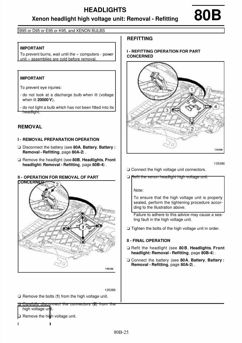
HEADLIGHTS
Xenon headlight high voltage unit: Removal - Refitting
B95 or D95 or E95 or K95, and XENON BULBS
80B
REMOVAL
I - REMOVAL PREPARATION OPERATION
a Disconnect the battery (see 80A, Battery, Battery :Removal - Refitting, page 80A-2) .
a Remove the headlight (see 80B, Headlights, Frontheadlight: Removal - Refitting, page 80B-4) .
II - OPERATION FOR REMOVAL OF PARTCONCERNED
a Remove the bolts (1) from the high voltage unit.
a Carefully disconnect the connectors (2) from thehigh voltage unit.
a Remove the high voltage unit.
REFITTING
I - REFITTING OPERATION FOR PARTCONCERNED
a Connect the high voltage unit connectors.
a Refit the xenon headlight high voltage unit.
a Tighten the bolts of the high voltage unit in order.
II - FINAL OPERATION
a Refit the headlight (see 80B, Headlights, Frontheadlight: Removal - Refitting, page 80B-4) .
a Connect the battery (see 80A, Battery, Battery :Removal - Refitting, page 80A-2) .
IMPORTANT
To prevent burns, wait until the « computers - power
unit » assemblies are cold before removal.
IMPORTANT
To prevent eye injuries:
- do not look at a discharge bulb when lit (voltagewhen lit 20000 V),
- do not light a bulb which has not been fitted into itsheadlight.
135386
135386
Note:
To ensure that the high voltage unit is properlysealed, perform the tightening procedure accor-ding to the illustration above.
Failure to adhere to this advice may cause a sea-ling fault in the high voltage unit.

8/6/2019 8 - Electrical Equipment
http://slidepdf.com/reader/full/8-electrical-equipment 46/29480B-26
HEADLIGHTS
Front lighting computer: Removal - Refitting
B95 or D95 or E95 or K95, and XENON BULBS
80B
REMOVAL
I - REMOVAL PREPARATION OPERATION
a Switch off the ignition.
a Disconnect the battery (see 80A, Battery, Battery :Removal - Refitting, page 80A-2) .
a Remove the dashboard lower trim (see Lower sec-tion of dashboard trim: Removal - Refitting)(57A, Interior equipment).
a Remove the glovebox (see Glovebox: Removal -Refitting) (57A, Interior equipment).
a Remove the UCH (see 87B, Passenger compart-ment connection unit, UCH: Removal - Refitting,page 87B-1) .
a Cut the plastic clip (1) on the passenger compart-ment fuse and relay box.
a Disconnect the connectors (2) .
a Unclip the passenger compartment fuse and relaybox.
aMove aside the passenger compartment relay/fusebox.
Essential equipment
diagnostic tool
LEFT-HAND DRIVE
RIGHT-HAND DRIVE
136960

8/6/2019 8 - Electrical Equipment
http://slidepdf.com/reader/full/8-electrical-equipment 47/294

8/6/2019 8 - Electrical Equipment
http://slidepdf.com/reader/full/8-electrical-equipment 48/294

8/6/2019 8 - Electrical Equipment
http://slidepdf.com/reader/full/8-electrical-equipment 49/29481A-2
REAR LIGHTING
Rear lighting: List and location of components
B95
81A
High level brake light
Rear fog lights
Number plate lights
135332
135332
135333

8/6/2019 8 - Electrical Equipment
http://slidepdf.com/reader/full/8-electrical-equipment 50/29481A-3
REAR LIGHTING
Rear lighting: List and location of components
D95
81A
I - LIST OF COMPONENTS
The "rear lighting" equipment consists of:
- rear lights on the wing
- rear light bulbs
- a high level brake light
- rear fog lights
- rear fog light bulbs
- the number plate lights
II - LOCATION OF COMPONENTS
Rear lights on the wing
Rear light bulbs
High level brake light
Rear fog lights
137340
135359
(1) Direction indicator bulb
(2) Brake light and side light bulb
(3) Reversing light bulb
137340
137340

8/6/2019 8 - Electrical Equipment
http://slidepdf.com/reader/full/8-electrical-equipment 51/29481A-4
REAR LIGHTING
Rear lighting: List and location of components
D95
81A
Rear fog light bulb
Number plate lights
135336
135333

8/6/2019 8 - Electrical Equipment
http://slidepdf.com/reader/full/8-electrical-equipment 52/294

8/6/2019 8 - Electrical Equipment
http://slidepdf.com/reader/full/8-electrical-equipment 53/29481A-6
REAR LIGHTING
Rear light on wing: Removal - Refitting
B95
81A
REMOVAL
OPERATION FOR REMOVAL OF PARTCONCERNED
a Remove the access flap (1) .
a Remove the bolts (2) from the rear light on the wing.
a Unclip and separate the rear light on the wing panel.
a Disconnect the connector from the rear light on thewing.
a Remove the rear light on the wing.
When replacing the rear light on the wing
a Remove the bulbs from the rear light on the wing(see 81A, Rear lighting, Rear light bulb: Removal- Refitting, page 81A-8) .
REFITTING
REFITTING OPERATION FOR PART CONCERNED
When replacing the rear light on the wing
a Refit the bulbs for the rear light on the wing (see81A, Rear lighting, Rear light bulb: Removal - Re-fitting, page 81A-8) .
a Connect the connector for the rear light on the wing.
a Refit:
- the rear light on the wing,
- the access flap.
135348
135363

8/6/2019 8 - Electrical Equipment
http://slidepdf.com/reader/full/8-electrical-equipment 54/29481A-7
REAR LIGHTING
Rear opening element light: Removal - Refitting
B95
81A
The rear lights are split into two sections, one on thewing and the other on the tailgate.
REMOVAL
OPERATION FOR REMOVAL OF PARTCONCERNED
a Unclip the tailgate trim flap (1) using the tool (Car.1363).
a Remove the rear opening element light bolts (2) .
a Unclip and separate the rear opening element light.
a Unclip and disconnect the connector for the rearopening element light.
a Extract the wiring for the rear opening element light
on the luggage compartment lid.
a Remove the rear opening element light.
When replacing the rear opening element light
a Remove the rear opening element light bulbs (see81A, Rear lighting, Rear light bulb: Removal - Re-fitting, page 81A-8) .
REFITTING
REFITTING OPERATION FOR PART CONCERNED
When replacing the rear opening element light
a Refit the rear opening element light bulbs (see 81A,
Rear lighting, Rear light bulb: Removal - Refit-ting, page 81A-8) .
a Fit the wiring for the rear opening element light to theluggage compartment lid.
a Connect and clip on the rear opening element light.
a Refit the rear opening element light.
a Clip on the tailgate trim flap.
Essential special tooling
Car. 1363 Set of trim removal levers.
135347
135337

8/6/2019 8 - Electrical Equipment
http://slidepdf.com/reader/full/8-electrical-equipment 55/294

8/6/2019 8 - Electrical Equipment
http://slidepdf.com/reader/full/8-electrical-equipment 56/294

8/6/2019 8 - Electrical Equipment
http://slidepdf.com/reader/full/8-electrical-equipment 57/29481A-10
REAR LIGHTING
Rear light bulb: Removal - Refitting
D95
81A
REMOVAL
I - REMOVAL PREPARATION OPERATION
a Remove the rear light on the wing (see 81A, Rear li-ghting, Rear light on wing: Removal - Refitting,page 81A-5) .
II - OPERATION FOR REMOVAL OF PARTCONCERNED
a Remove the bulb holder plate for the rear light on thewing by pressing on the clips (
1) .
a Remove:
- the indicator bulb (2) ,
- the brake light and side light bulb (3) ,
- the reversing light bulb (4) .
REFITTING
I - REFITTING OPERATION FOR PARTCONCERNED
a
a Refit:
- the reversing light bulb,
- the brake light and side light bulb,
- the indicator bulb,
- the bulb holder plate onto the rear light on the wing.
II - FINAL OPERATION
a Refit the rear light on the wing (see 81A, Rear li-ghting, Rear light on wing: Removal - Refitting,page 81A-5) .
135360
135359
Note:
When replacing a bulb, only use approved bulbs.

8/6/2019 8 - Electrical Equipment
http://slidepdf.com/reader/full/8-electrical-equipment 58/294

8/6/2019 8 - Electrical Equipment
http://slidepdf.com/reader/full/8-electrical-equipment 59/294

8/6/2019 8 - Electrical Equipment
http://slidepdf.com/reader/full/8-electrical-equipment 60/29481A-13
REAR LIGHTING
Third brake light: Removal - Refitting
D95
81A
REMOVAL
I - REMOVAL PREPARATION OPERATION
aRemove the tailgate spoiler (see Tailgate spoiler:Removal - Refitting) (56A, Exterior equipment).
II - OPERATION FOR REMOVAL OF PARTCONCERNED
a Remove the high level brake light screws (1) .
a Remove the high level brake light at (3) by pressingon the clips (2) .
In the event of replacement
a Unclip the rear screen washer jet by pressing on theclips (4) .
REFITTING
I - REFITTING OPERATION FOR PARTCONCERNED
a
In the event of replacement
a Clip the rear screen washer jet on the high level bra-
ke light.
a Refit the high level brake light on the tailgate spoiler.
II - FINAL OPERATION
a Refit the tailgate spoiler (see Tailgate spoiler: Re-
moval - Refitting) (56A, Exterior equipment).
137980
137854
Note:
If the LEDs are faulty, replace the complete highlevel brake light.

8/6/2019 8 - Electrical Equipment
http://slidepdf.com/reader/full/8-electrical-equipment 61/29481A-14
REAR LIGHTING
Rear fog light bulb: Removal - Refitting
D95
81A
REMOVAL
I - REMOVAL PREPARATION OPERATION
a Position the vehicle on a two-post lift (see Vehicle:Towing and lifting) (02A, Lifting equipment).
II - OPERATION FOR REMOVAL OF PARTCONCERNED
a Disconnect the connector (1) from the rear fog light.
a Remove:
- the bulb holder of the rear fog light by turning it aquarter of a turn clockwise (2) ,
- the rear fog light bulb from the bulb holder.
REFITTING
REFITTING OPERATION FOR PART CONCERNED
a
a Refit:
- the rear fog light bulb to the bulb holder,
- the bulb holder to the rear fog light by turning it aquarter of a turn anti-clockwise.
a Connect the rear fog light connector.
135336
135335
Note:
When replacing a bulb, only use approved bulbs.

8/6/2019 8 - Electrical Equipment
http://slidepdf.com/reader/full/8-electrical-equipment 62/29481A-15
REAR LIGHTING
Rear fog lights: Removal - Refitting
D95
81A
REMOVAL
OPERATION FOR REMOVAL OF PARTCONCERNED
a Remove the rear fog light bolt (1) .
a Disconnect the rear fog light connector (2) .
a Unclip the rear fog light.
a Remove the rear fog light.
When replacing the rear fog light
a Remove the rear fog light bulb (see 81A, Rear li-ghting, Rear fog light bulb: Removal - Refitting,page 81A-14) .
REFITTING
REFITTING OPERATION FOR PART CONCERNED
When replacing the rear fog light
a Refit the rear fog light bulb (see 81A, Rear lighting,Rear fog light bulb: Removal - Refitting, page81A-14) .
a Connect the rear fog light connector.
a Clip the rear fog light onto the rear bumper.
a Refit the rear fog light.
135336

8/6/2019 8 - Electrical Equipment
http://slidepdf.com/reader/full/8-electrical-equipment 63/29481A-16
REAR LIGHTING
Number plate light: Removal - Refitting
B95 or D95 or E95 or K95
81A
REMOVAL
OPERATION FOR REMOVAL OF PARTCONCERNED
a Unclip the number plate light using a small flat-bladescrewdriver.
a Disconnect the number plate light connector.
When replacing the number plate light
a Unclip the translucent cover (1) from the numberplate light.
a Remove the number plate light bulb.
REFITTING
REFITTING OPERATION FOR PART CONCERNED
When replacing the number plate light
a
a Refit:
- the bulb for the number plate light,
- the number plate light translucent cover.
a Connect the connector to the number plate light.
a Clip the number plate light onto the rear bumper.135334
121080
Note:
When replacing a bulb, only use approved bulbs.

8/6/2019 8 - Electrical Equipment
http://slidepdf.com/reader/full/8-electrical-equipment 64/29481B-1
INTERIOR LIGHTING
Interior lights: List and location of components
B95 or D95 or E95 or K95
81B
I - LIST OF COMPONENTS
The interior lighting consists of:
- lower door lights (see 81B, Interior lighting, Lowerdoor light: Removal - Refitting, page 81B-5) .
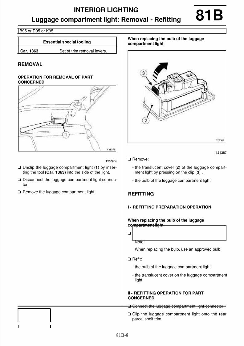
- a luggage compartment light (see 81B , Interior li-ghting, Luggage compartment light: Removal -Refitting, page 81B-8) .
- courtesy lights (see 81B, Interior lighting, Courtesylight: Removal - Refitting, page 81B-3) .
- vanity lights (see 81B, Interior lighting, Vanity light:Removal - Refitting, page 81B-6)
- a glovebox light (see 81B, Interior lighting, Glove-box light: Removal - Refitting, page 81B-7) .
II - POSITION OF THE COMPONENTS
Lower door light
Luggage compartment light
Courtesy light
B95 or D95 or K95
B95 or D95 or K95
135368
B95 or D95 or K95
135367
135371

8/6/2019 8 - Electrical Equipment
http://slidepdf.com/reader/full/8-electrical-equipment 65/294

8/6/2019 8 - Electrical Equipment
http://slidepdf.com/reader/full/8-electrical-equipment 66/29481B-3
INTERIOR LIGHTING
Courtesy light: Removal - Refitting
B95 or D95 or E95 or K95
81B
REMOVAL
OPERATION FOR REMOVAL OF PARTCONCERNED
a
Front courtesy light
a Unclip the courtesy light (2) from the headlining
using the tool (Car. 1363) by pressing on the clips(1) .
a Disconnect the courtesy light connector.
a Remove the courtesy light.
When replacing the courtesy light bulbs
a Unclip:
- the translucent cover from the courtesy light at (3) ,
- the courtesy light bulbs.
Essential special tooling
Car. 1363 Set of trim removal levers.
135374
Note:
Removal is carried out by pressing on the twoclips (1) using the tool (Car. 1363).
135373
135374

8/6/2019 8 - Electrical Equipment
http://slidepdf.com/reader/full/8-electrical-equipment 67/294

8/6/2019 8 - Electrical Equipment
http://slidepdf.com/reader/full/8-electrical-equipment 68/29481B-5
INTERIOR LIGHTING
Lower door light: Removal - Refitting 81B
REMOVAL
OPERATION FOR REMOVAL OF PARTCONCERNED
a Unclip the lower door light (1) using the tool (Car.1363).
a Disconnect the connector from the lower door light.
a Remove the lower door light.
REFITTING
REFITTING OPERATION FOR PART CONCERNED
a
a Connect the connector to the lower door light.a Clip the lower door light onto the front side door trim.
Essential special tooling
Car. 1363 Set of trim removal levers.
135377
Note:
When replacing the bulb, use an approved bulb.

8/6/2019 8 - Electrical Equipment
http://slidepdf.com/reader/full/8-electrical-equipment 69/29481B-6
INTERIOR LIGHTING
Vanity light: Removal - Refitting
B95 or D95 or K95
81B
REMOVAL
OPERATION FOR REMOVAL OF PARTCONCERNED
a Unclip the vanity light from the headlining (1) usingthe tool (Car. 1363).
a Disconnect the vanity light connector.
a Remove the vanity light.
REFITTING
REFITTING OPERATION FOR PART CONCERNED
a
a Connect the vanity light connector.
a Clip the vanity light onto the headlining.
Essential special tooling
Car. 1363 Set of trim removal levers.
135376
Note:
When replacing the bulb, use an approved bulb.

8/6/2019 8 - Electrical Equipment
http://slidepdf.com/reader/full/8-electrical-equipment 70/29481B-7
INTERIOR LIGHTING
Glovebox light: Removal - Refitting
B95 or D95 or E95 or K95
81B
REMOVAL
I - REMOVAL PREPARATION OPERATION
a Unclip the cover from the storage compartment light
switch (1) .
a Remove the glovebox (see Glovebox: Removal -Refitting) (57A, Interior equipment).
II - OPERATION FOR REMOVAL OF PARTCONCERNED
a Unclip the storage compartment light (2) from thedashboard using the tool (Car. 1363).
a Disconnect the storage compartment light connector
a Remove the storage compartment light.
REFITTINGa
a Connect the storage compartment light connector.
a Clip the storage compartment light onto the dash-board.
FINAL OPERATION
a Refit the glovebox (see Glovebox: Removal - Refit-ting) (57A, Interior equipment).
a Clip on the storage compartment light switch cover.
Essential special tooling
Car. 1363 Set of trim removal levers.
LEFT-HAND DRIVE
135369
135378
Note:
When replacing the bulb, use an approved bulb.
LEFT-HAND DRIVE
8/6/2019 8 - Electrical Equipment
http://slidepdf.com/reader/full/8-electrical-equipment 71/294
8/6/2019 8 - Electrical Equipment
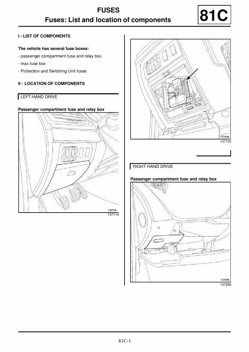
http://slidepdf.com/reader/full/8-electrical-equipment 72/29481C-1
FUSES
Fuses: List and location of components 81CI - LIST OF COMPONENTS
The vehicle has several fuse boxes:
- passenger compartment fuse and relay box
- max fuse box
- Protection and Switching Unit fuses
II - LOCATION OF COMPONENTS
Passenger compartment fuse and relay box
Passenger compartment fuse and relay box
LEFT-HAND DRIVE
137114
137120
RIGHT-HAND DRIVE
137295

8/6/2019 8 - Electrical Equipment
http://slidepdf.com/reader/full/8-electrical-equipment 73/294

8/6/2019 8 - Electrical Equipment
http://slidepdf.com/reader/full/8-electrical-equipment 74/294

8/6/2019 8 - Electrical Equipment
http://slidepdf.com/reader/full/8-electrical-equipment 75/294

8/6/2019 8 - Electrical Equipment
http://slidepdf.com/reader/full/8-electrical-equipment 76/29482A-3
ENGINE IMMOBILISER
Start button: Removal - Refitting
B95 or D95 or K95
82A
REMOVAL
I - REMOVAL PREPARATION OPERATION
a Switch off the ignition.
a Remove the centre front panel (see Centre frontpanel: Removal - Refitting) (57A, Interior equip-ment).
II - OPERATION FOR REMOVAL OF PARTCONCERNED
a Remove the start button by pressing the clips (1) .
REFITTING
I - REFITTING OPERATION FOR PARTCONCERNED
a Clip the start button onto the centre front cover.
II - FINAL OPERATION
a Refit the centre front panel (see Centre front panel:Removal - Refitting) (57A, Interior equipment).
136682
128097

8/6/2019 8 - Electrical Equipment
http://slidepdf.com/reader/full/8-electrical-equipment 77/29482A-4
ENGINE IMMOBILISER
Steering column electric lock: Removal - Refitting 82A
REMOVAL
I - REMOVAL PREPARATION OPERATION
a To lock the airbag computer, apply the before repairprocedure using the diagnostic tool :
- connect the diagnostic tool,
- select the “Airbag computer”,
- go to repair mode,
- display the "Before/after repair procedure" for thecomputer selected,
- carry out the operations described in the "Beforerepair procedure" section.
a Switch off the ignition.
a Remove:
- the dashboard lower trim (see Lower section ofdashboard trim: Removal - Refitting) (57A, Inte-rior equipment),
- the driver's side front footwell air distribution duct(see A-pillar air distribution duct: Removal - Re-fitting) (61A, Heating).
a Position the steering wheel in the highest positionand pulled fully towards oneself.
II - OPERATION FOR REMOVAL OF PARTCONCERNED
a
a Remove:
- the bolt (1) from the electric steering column lock,
- the electric steering column lock.
a Disconnect the connector (2) from the electric stee-ring column lock.
REFITTING
I - REFITTING PREPARATION OPERATION
a Always replace the bolt of the electric steering colu-mn lock.
a Always replace the electric steering column lock if itfalls on the ground or was impacted.
II - REFITTING OPERATION FOR PARTCONCERNED
a Position the electric steering column lock in the stee-ring column.
a Torque tighten the electric steering column lockbolt (8 N.m).
a Connect the electric steering column lock connector.
Essential equipment
diagnostic tool
Tightening torquesm
electric steering columnlock bolt
8 N.m
Note:
To remove the electric steering column lock, the air-bag computer must be locked.
This operation enables the steering column to beunlocked.
Note:
Do not fit a steering column lock that shows signsof impact (risk of an immobilising fault).
136675
WARNING
The bolt for the electric steering column lock hasa left-hand thread. It unscrews in a clockwise
direction.

8/6/2019 8 - Electrical Equipment
http://slidepdf.com/reader/full/8-electrical-equipment 78/294

8/6/2019 8 - Electrical Equipment
http://slidepdf.com/reader/full/8-electrical-equipment 79/294

8/6/2019 8 - Electrical Equipment
http://slidepdf.com/reader/full/8-electrical-equipment 80/29482A-7
ENGINE IMMOBILISER
Starting aerial: Removal - Refitting
DOOR OPEN SYST. 433 NML
82A
To enable starting in « hands-free » mode, the vehicleis fitted with 3 aerials:
- an aerial on the dashboard,
- an aerial on the centre console,
- an aerial on the luggage compartment floor.
To locate the 3 starter aerials (see 82A, Engine immo-biliser, Immobiliser system: List and location ofcomponents , page 82A-1) .
REMOVAL
I - REMOVAL PREPARATION OPERATION
a Switch off the ignition.
1 - Dashboard aerial
a Remove the centre console (see Centre console:Removal - Refitting) (57A, Interior equipment).
2 - Centre console aerial
a Unclip the centre console rear panel.
a Disconnect the accessories socket connector (1) .
3 - Luggage compartment floor aerial
a Remove the luggage compartment carpet (see Lug-gage compartment carpet: Removal - Refitting)(71A, Body internal trim).
II - OPERATION FOR REMOVAL OF PARTCONCERNED
a
a Unclip the starter aerial at (2) using the (Car. 1363).
Essential special tooling
Car. 1363 Set of trim removal levers.
136677
101628
WARNING
The retaining clips are fragile; handle with care.
124212

8/6/2019 8 - Electrical Equipment
http://slidepdf.com/reader/full/8-electrical-equipment 81/294

8/6/2019 8 - Electrical Equipment
http://slidepdf.com/reader/full/8-electrical-equipment 82/29482A-9
ENGINE IMMOBILISER
Remote door locking control battery: Removal - Refitting 82AREMOVAL
OPERATION FOR REMOVAL OF PARTCONCERNED
a Unclip the safety key (1) by pressing the clip (2) .
a Unclip the battery cover (3) from the door locking re-mote control.
a Remove the battery (4) from the remote control for
door locking.
REFITTING
I - REFITTING PREPARATION OPERATION
a
II - REFITTING OPERATION FOR PART
CONCERNED
a Refit:
- the door locking remote control battery,
- the door locking remote control battery cover,
- the emergency key.
125112
125113
125114
WARNING
To ensure that the remote control operates cor-rectly, take care not to damage the battery con-tacts.
Only handle the new battery with dry, grease-freehands or wearing clean gloves to avoid any riskof dirt and oxidation on the battery.

8/6/2019 8 - Electrical Equipment
http://slidepdf.com/reader/full/8-electrical-equipment 83/29482B-1
HORN
Horn: Removal - Refitting 82B
REMOVAL
I - REMOVAL PREPARATION OPERATION
a Position the vehicle on a two-post lift (see Vehicle:Towing and lifting) (02A, Lifting equipment).
a Remove:
- the front wheels (see Wheel: Removal - Refitting)(35A, Wheels and tyres),
- the front wheel arch liners (see Front wheel archliner: Removal - Refitting) (55A, Exterior protec-tion),
- the front bumper (see Front bumper: Removal -Refitting) (55A, Exterior protection).
a Unclip the front upper deflector at (1) .
a Remove the front upper deflector.
II - OPERATION FOR REMOVAL OF PARTCONCERNED
a Disconnect the horn connector (2) .
a Remove:
- the horn nut (3) ,
- the horn.
REFITTING
I - REFITTING OPERATION FOR PARTCONCERNED
a Refit the horn.
a Torque tighten the horn nut (21 N.m).
a Connect the horn connector.
II - FINAL OPERATION
a Refit:
- the front upper deflector,
- the front bumper (see Front bumper: Removal -Refitting) (55A, Exterior protection),
- the front wheel arch liners (see Front wheel archliner: Removal - Refitting) (55A, Exterior protec-tion),
- the front wheels (see Wheel: Removal - Refitting)(35A, Wheels and tyres).
Tightening torquesm
horn nut 21 N.m
135786
135784

8/6/2019 8 - Electrical Equipment
http://slidepdf.com/reader/full/8-electrical-equipment 84/29482C-1
ALARM
Alarm: List and location of components
ALARM PRE-EQUIPMENT
82C
COMPONENT LOCATION
These vehicles are pre-wired to be fitted with a RE-NAULT-approved alarm.
The specific connector is located behind the rear left-hand wheel arch liner.
To access the connector, remove the rear left-hand
wheel arch liner (see Rear wheel arch lining: Remo-val - Refitting) (71A, Body internal trim).
138066

8/6/2019 8 - Electrical Equipment
http://slidepdf.com/reader/full/8-electrical-equipment 85/294

8/6/2019 8 - Electrical Equipment
http://slidepdf.com/reader/full/8-electrical-equipment 86/29483A-2
INSTRUMENT PANEL
Instrument panel: Removal - Refitting
B95 or D95 or K95
83A
II - FINAL OPERATION
a Connect the battery (see 80A, Battery, Battery :Removal - Refitting, page 80A-2) .
a
In the event of a replacement, apply the after repairprocedure using the diagnostic tool :
- connect the diagnostic tool,
- select "Instrument panel",
- go to repair mode,
- display the "Before/after repair procedure" for thecomputer selected,
- carry out the operations described in the "After re-
pair procedure" section.

8/6/2019 8 - Electrical Equipment
http://slidepdf.com/reader/full/8-electrical-equipment 87/294

8/6/2019 8 - Electrical Equipment
http://slidepdf.com/reader/full/8-electrical-equipment 88/29483C-2
ON-BOARD TELEMATICS SYSTEM
Navigation: List and location of components
RADIO NO 06 or RADIO NO 07
83C
Navigation aerial
Navigation computer
The navigation computer is located in the glovebox.
Central control
128435
RADIO NO 07
137662
136721

8/6/2019 8 - Electrical Equipment
http://slidepdf.com/reader/full/8-electrical-equipment 89/294

8/6/2019 8 - Electrical Equipment
http://slidepdf.com/reader/full/8-electrical-equipment 90/29483C-4
ON-BOARD TELEMATICS SYSTEM
Radio navigation system: Removal - Refitting
B95 or D95 or K95, and RADIO NO 06 or RADIO NO 07
83C
- select "front panel CD changer" in the section "Listof components stored by this computer",
- carry out the operations described in the "After re-pair procedure" section.

8/6/2019 8 - Electrical Equipment
http://slidepdf.com/reader/full/8-electrical-equipment 91/29483C-5
ON-BOARD TELEMATICS SYSTEM
Navigation computer: Removal - Refitting
B95 or D95 or K95, and RADIO NO 07
83C
REMOVAL
I - REMOVAL PREPARATION OPERATION
a Switch off the ignition.
a Remove the glovebox (see Glovebox: Removal -Refitting) (57A, Interior equipment).
a Remove:
- the bolts (1) from the tuner-amplifier and the navi-gation computer supports,
- the tuner-amplifier and the navigation computersupports.
II - OPERATION FOR REMOVAL OF PARTCONCERNED
a Disconnect the navigation computer connectors.
a Disconnect the aerial.
Essential special tooling
Ms. 1821 Radio removal tool (4-hole)
Essential equipment
diagnostic tool
WARNING
To prevent damaging the navigation system, wait1 minute after switching off the + after ignitionfeed.
138068
138069
WARNING
To ensure correct operation:
- do not pinch the aerial cable,
- do not bend the aerial cable,
- do not force the aerial cable when refitting.

8/6/2019 8 - Electrical Equipment
http://slidepdf.com/reader/full/8-electrical-equipment 92/29483C-6
ON-BOARD TELEMATICS SYSTEM
Navigation computer: Removal - Refitting
B95 or D95 or K95, and RADIO NO 07
83C
a Remove the navigation computer from its supportusing two tools (Ms. 1821) (2) .
REFITTING
I - REFITTING OPERATION FOR PARTCONCERNED
a Refit the navigation computer onto its support.
a Connect:
- the aerial,
- the connectors.
II - FINAL OPERATION
a Refit:
- the tuner-amplifier and the navigation computersupports,
- the bolts for the tuner-amplifier and the navigationcomputer supports,
- the glovebox (see Glovebox: Removal - Refit-ting) (57A, Interior equipment).
a In the event of a replacement, apply the after repairprocedure using the diagnostic tool :
- connect the diagnostic tool,
- select “Navigation computer”,- go to repair mode,
- display the "Before/after repair procedure" for thecomputer selected,
- carry out the operations described in the "After re-pair procedure" section.
137664
WARNING
To ensure correct operation:
- do not pinch the aerial cable,
- do not bend the aerial cable,
- do not force the aerial cable when refitting.

8/6/2019 8 - Electrical Equipment
http://slidepdf.com/reader/full/8-electrical-equipment 93/29483C-7
ON-BOARD TELEMATICS SYSTEM
Multimedia network interface unit: Removal - Refitting
B95 or D95 or K95, and RADIO NO 06 or RADIO NO 07
83C
REMOVAL
I - REMOVAL PREPARATION OPERATION
a Switch off the ignition.
a Disconnect the battery (see 80A, Battery, Battery :Removal - Refitting, page 80A-2) .
a Remove the dashboard (see Dashboard: Removal- Refitting) (57A, Interior equipment).
II - OPERATION FOR REMOVAL OF PARTCONCERNED
a Unclip the multimedia network interface unit at (1) .
a Disconnect the multimedia network interface unitconnector.
aRemove the multimedia network interface unit.
REFITTING
I - REFITTING OPERATION FOR PARTCONCERNED
a Connect the multimedia network interface unit con-nector.
a Clip the multimedia network interface unit onto the
dashboard cross member.
II - FINAL OPERATION
a Refit the dashboard (see Dashboard: Removal -Refitting) (57A, Interior equipment).
a Connect the battery (see 80A, Battery, Battery :Removal - Refitting, page 80A-2) .
a In the event of a replacement, apply the after repairprocedure using the diagnostic tool :
- connect the diagnostic tool,
- select "Interface computer between the vehicle andmultimedia networks",
- go to repair mode,
Essential equipment
diagnostic tool
Note:
The multimedia network interface unit is locatedbehind the instrument panel, regardless of the dri-ver's position.
WARNING
To prevent damaging the navigation system, wait1 minute after switching off the + after ignitionfeed. 138067

8/6/2019 8 - Electrical Equipment
http://slidepdf.com/reader/full/8-electrical-equipment 94/29483C-8
ON-BOARD TELEMATICS SYSTEM
Multimedia network interface unit: Removal - Refitting
B95 or D95 or K95, and RADIO NO 06 or RADIO NO 07
83C
- display the "Before/after repair procedure" for thecomputer selected,
- select “Multimedia network interface unit” in the“List of components stored in the computer” sec-
tion,
- carry out the operations described in the "After re-pair procedure" section.

8/6/2019 8 - Electrical Equipment
http://slidepdf.com/reader/full/8-electrical-equipment 95/29483C-9
ON-BOARD TELEMATICS SYSTEM
Central control: Removal - Refitting
B95 or D95 or K95, and RADIO NO 07
83C
REMOVAL
I - REMOVAL PREPARATION OPERATION
aSwitch off the ignition.
a Remove the centre console upper panel (see Cen-tre console: Removal - Refitting) (57A, Interior
equipment).
II - OPERATION FOR REMOVAL OF PARTCONCERNED
a Remove:
- the bolts (1) from the central control support,
- the central control support.
a Unclip the central control from its support by pres-sing on the clips (2)
REFITTING
I - REFITTING OPERATION FOR PART
CONCERNED
a Clip the central control onto its support.
a Refit:
- the central control support to the centre consoleupper panel,
- the bolts for the central control support.
II - FINAL OPERATION
a Refit the centre console upper panel (see Centre
console: Removal - Refitting) (57A, Interior equip-ment).
WARNING
To prevent damaging the navigation system, wait1 minute after switching off the + after ignitionfeed.
137966
137967

8/6/2019 8 - Electrical Equipment
http://slidepdf.com/reader/full/8-electrical-equipment 96/294
8/6/2019 8 - Electrical Equipment
http://slidepdf.com/reader/full/8-electrical-equipment 97/29483C-11
ON-BOARD TELEMATICS SYSTEM
Navigation screen: Removal - Refitting
B95 or D95 or K95, and RADIO NO 06 or RADIO NO 07
83C
a
a Connect the navigation screen connector.
a Refit:
- the navigation screen on the dashboard,
- the navigation screen bolts.
a Clip on the navigation screen upper trim.
WARNING
Do not press on the screen as this may damage
it.

8/6/2019 8 - Electrical Equipment
http://slidepdf.com/reader/full/8-electrical-equipment 98/29483D-1
CRUISE CONTROL
Cruise control / speed limiter: List and location of components
CRUISE CONTROL
83D
I - LIST OF COMPONENTS
The "cruise control" function is composed of:
- a switch- steering column switches
- a brake light switch
The steering column switches cannot be separatedfrom the steering wheel.
To remove the steering wheel (see Steering wheel:Removal - Refitting) (36B, Power-assisted steering).
To remove the brake light switch (see Brake pedal
switch: Removal - Refitting) (37A, Mechanical com-ponent controls).
- a clutch pedal switch
To remove the clutch pedal switch (see Clutch pedalswitch: Removal - Refitting) (37A, Mechanical com-ponent controls).
II - LOCATION OF COMPONENTS
Switch
Steering column switches
5 SPEED MANUAL GBOX or 6 SPEED MANUALGBOX
B95 or D95 or K95
136721
136723

8/6/2019 8 - Electrical Equipment
http://slidepdf.com/reader/full/8-electrical-equipment 99/29483D-2
CRUISE CONTROL
Cruise control / speed limiter: List and location of components
CRUISE CONTROL
83D
Brake switch
Brake switch
Clutch switch
LEFT-HAND DRIVE
134356
RIGHT-HAND DRIVE
134659
LEFT-HAND DRIVE, and 5 SPEED MANUALGBOX or 6 SPEED MANUAL GBOX
134695

8/6/2019 8 - Electrical Equipment
http://slidepdf.com/reader/full/8-electrical-equipment 100/29483D-3
CRUISE CONTROL
Cruise control / speed limiter: List and location of components
CRUISE CONTROL
83D
Clutch switch
RIGHT-HAND DRIVE, and 5 SPEED MANUALGBOX or 6 SPEED MANUAL GBOX
137154

8/6/2019 8 - Electrical Equipment
http://slidepdf.com/reader/full/8-electrical-equipment 101/29483D-4
CRUISE CONTROL
Switch: Removal - Refitting
B95 or D95 or K95, and CRUISE CONTROL
83D
REMOVAL
I - REMOVAL PREPARATION OPERATION
a Switch off the ignition.
a Remove the centre console upper panel (see Cen-tre console: Removal - Refitting) (57A, Interiorequipment).
II - OPERATION FOR REMOVAL OF PARTCONCERNED
a Disconnect the cruise control switch connector.
a Unclip the cruise control switch from the centre con-sole upper panel by pressing on the clips (1) .
REFITTING
I - REFITTING OPERATION FOR PARTCONCERNED
a Clip the cruise control switch onto the centre consoleupper panel.
a Connect the cruise control switch connector.
II - FINAL OPERATION
a Refit the centre console upper panel (see Centreconsole: Removal - Refitting) (57A, Interior equip-ment).
a Switch on the ignition.
a Apply the after repair procedure using the diagnos-tic tool :
- connect the diagnostic tool,
- select "Injection computer",
- go to repair mode,
- display the "Before/after repair procedure" for the
computer selected,
- select "Cruise control/speed limiter on/off switch" in
the "List of components controlled by this compu-ter" section,
- carry out the operations described in the "After re-pair procedure" section.
Essential equipment
diagnostic tool
137969

8/6/2019 8 - Electrical Equipment
http://slidepdf.com/reader/full/8-electrical-equipment 102/29484A-1
CONTROL - SIGNALSUnder steering wheel control assembly: List and location of components 84A
I - LIST OF COMPONENTS
The "steering column switch assembly" equipmentincludes:
- a steering column switch assembly
- hazard warning lights and central door control
- a lighting dimmer
- an exterior rear view mirror control switch
- a remote headlight beam adjustment control
- an ESP inhibitor switch
- a parking distance control switch
To remove the parking distance control switch (see
87F, Parking distance control, Parking proximitysensor switch: Removal - Refitting, page 87F-4) .
- a heated seat cover switch
II - LOCATION OF COMPONENTS
Steering column switch assembly
Hazard warning lights switch and central doorcontrol
WITHOUT XENON BULBS
ESP
FR AND RR PROX RADAR
FRONT SEAT WITH HEATING
136723
137961

8/6/2019 8 - Electrical Equipment
http://slidepdf.com/reader/full/8-electrical-equipment 103/29484A-2
CONTROL - SIGNALSUnder steering wheel control assembly: List and location of components 84A
Lighting dimmer
Exterior rear view mirror control switch
Remote headlight beam adjustment control
ESP inhibitor switch
136723
124199
WITHOUT XENON BULBS
136723
ESP
136723

8/6/2019 8 - Electrical Equipment
http://slidepdf.com/reader/full/8-electrical-equipment 104/29484A-3
CONTROL - SIGNALSUnder steering wheel control assembly: List and location of components 84A
Parking distance control switch
To remove the parking distance control switch (see87F, Parking distance control, Parking proximitysensor switch: Removal - Refitting, page 87F-4) .
Heated seat cover switch
Heated seat cover switch
FR AND RR PROX RADAR
136723
FRONT SEAT WITH HEATING
138062
FRONT SEAT TYPE 04, and FRONT SEAT WITHHEATING
138064

8/6/2019 8 - Electrical Equipment
http://slidepdf.com/reader/full/8-electrical-equipment 105/29484A-4
CONTROL - SIGNALS
Steering wheel controls assembly: Removal - Refitting 84A
REMOVAL
I - REMOVAL PREPARATION OPERATION
a
a Set the wheels straight ahead.
a Disconnect the battery (see 80A, Battery, Battery :Removal - Refitting, page 80A-2) .
a Remove the bolts (1) from the shells under the stee-ring wheel.
a Put the steering column into the lower position.
a Remove the upper cover.
a Place the steering column in the upper position.
a Remove the lower cover.
a Remove:
- the driver's front airbag (see 88C, Air bag and Pre-tensioners , Driver's front airbag: Removal - Re-fitting, page 88C-14) ,
- the steering wheel (see Steering wheel: Removal- Refitting) (36B, Power-assisted steering).
II - OPERATION FOR REMOVAL OF PARTCONCERNED
a Undo the bolt (2) without removing it.
a Use a flat-blade screwdriver at (3) to release the
steering column switch assembly.
a Remove the steering wheel control assembly.
a Disconnect the steering column switch assemblyconnectors.
a In the event of a replacement operation, remove theradio control satellite (see 86A, Radio, Radio con-trol satellite: Removal - Refitting, page 86A-18) .
Note:
The steering column switch assembly comprises:
- the windscreen wiper switch,
- the signalling light switch,
- the rotary switch,
- the steering wheel angle sensor.
These parts cannot be separated.
WARNING
Incorrect wheel alignment may damage therotary switch.
136716
WARNING
To prevent damaging the rotary switch, do notturn the mobile section of the rotary switch.
125366
RADIO NO 01 or RADIO NO 02 or RADIO NO 03or RADIO NO 04 or RADIO NO 05 or RADIO NO06 or RADIO NO 07
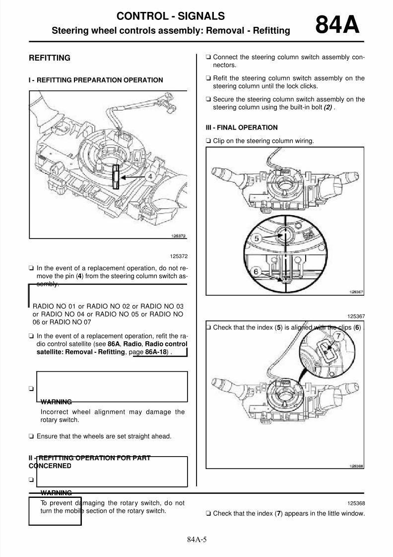
8/6/2019 8 - Electrical Equipment
http://slidepdf.com/reader/full/8-electrical-equipment 106/29484A-5
CONTROL - SIGNALS
Steering wheel controls assembly: Removal - Refitting 84AREFITTING
I - REFITTING PREPARATION OPERATION
a In the event of a replacement operation, do not re-move the pin (4) from the steering column switch as-sembly.
a In the event of a replacement operation, refit the ra-dio control satellite (see 86A, Radio, Radio controlsatellite: Removal - Refitting, page 86A-18) .
a
a Ensure that the wheels are set straight ahead.
II - REFITTING OPERATION FOR PARTCONCERNED
a
a Connect the steering column switch assembly con-nectors.
a Refit the steering column switch assembly on thesteering column until the lock clicks.
a Secure the steering column switch assembly on thesteering column using the built-in bolt (2) .
III - FINAL OPERATION
a Clip on the steering column wiring.
a Check that the index (5) is aligned with the clips (6) .
a Check that the index (7) appears in the little window.
125372
RADIO NO 01 or RADIO NO 02 or RADIO NO 03or RADIO NO 04 or RADIO NO 05 or RADIO NO06 or RADIO NO 07
WARNING
Incorrect wheel alignment may damage therotary switch.
WARNING
To prevent damaging the rotary switch, do notturn the mobile section of the rotary switch.
125367
125368
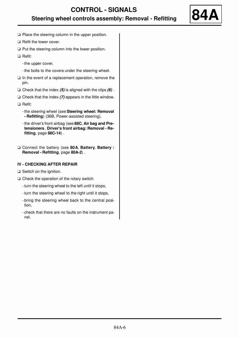
8/6/2019 8 - Electrical Equipment
http://slidepdf.com/reader/full/8-electrical-equipment 107/29484A-6
CONTROL - SIGNALS
Steering wheel controls assembly: Removal - Refitting 84Aa Place the steering column in the upper position.
a Refit the lower cover.
a Put the steering column into the lower position.
a Refit:
- the upper cover,
- the bolts to the covers under the steering wheel.
a In the event of a replacement operation, remove thepin.
a Check that the index (5) is aligned with the clips (6) .
a Check that the index (7) appears in the little window.
a Refit:
- the steering wheel (see Steering wheel: Removal
- Refitting) (36B, Power-assisted steering),- the driver's front airbag (see 88C, Air bag and Pre-tensioners , Driver's front airbag: Removal - Re-fitting, page 88C-14) .
a Connect the battery (see 80A, Battery, Battery :Removal - Refitting, page 80A-2) .
IV - CHECKING AFTER REPAIR
a Switch on the ignition.
a Check the operation of the rotary switch:
- turn the steering wheel to the left until it stops,
- turn the steering wheel to the right until it stops,
- bring the steering wheel back to the central posi-tion,
- check that there are no faults on the instrument pa-nel.

8/6/2019 8 - Electrical Equipment
http://slidepdf.com/reader/full/8-electrical-equipment 108/29484A-7
CONTROL - SIGNALS
Hazard warning lights switch and central locking: Removal - Refitting 84A
REMOVAL
I - REMOVAL PREPARATION OPERATION
a Switch off the ignition.
a Unclip the centre air vent using the tool (Car. 1363)(1) .
a Disconnect the hazard warning light and centraldoor locking switch connector.
II - OPERATION FOR REMOVAL OF PARTCONCERNED
a Unclip the hazard warning light and central door loc-king button by pressing on the clip ( 2) .
REFITTING
I - REFITTING PREPARATION OPERATION
a
II - REFITTING OPERATION FOR PARTCONCERNED
a Clip the hazard warning light and central door loc-king button onto the centre air vent.
III - FINAL OPERATION
a Connect the connector.
a Clip the centre air vent onto the dashboard.
Essential special tooling
Car. 1363 Set of trim removal levers.
137962
137982
Note:
The hazard warning light switch cannot be sepa-rated from the central door locking switch. In theevent of a replacement, replace the entire unit.

8/6/2019 8 - Electrical Equipment
http://slidepdf.com/reader/full/8-electrical-equipment 109/29484A-8
CONTROL - SIGNALS
ESP inhibitor switch: Removal - Refitting
ESP
84A
REMOVAL
I - REMOVAL PREPARATION OPERATION
a Switch off the ignition.
a Open the access flap to the passenger compartmentfuse box (1) .
a Unclip the switch plate at (2) using the (Car. 1363).
a Disconnect the switch plate connectors.
II - OPERATION FOR REMOVAL OF PARTCONCERNED
a Remove the ESP inhibitor switch by pressing on theclips (3) .
Essential special tooling
Car. 1363 Set of trim removal levers.
137114
137116
137112

8/6/2019 8 - Electrical Equipment
http://slidepdf.com/reader/full/8-electrical-equipment 110/29484A-9
CONTROL - SIGNALS
ESP inhibitor switch: Removal - Refitting
ESP
84A
REFITTING
I - REFITTING OPERATION FOR PARTCONCERNED
a Clip the ESP inhibitor switch onto the switch plate.
II - FINAL OPERATION
a Connect the switch plate connectors.
a Clip the switch plate on the dashboard lower trim.
a Close the access flap to the passenger compart-ment fuse box.

8/6/2019 8 - Electrical Equipment
http://slidepdf.com/reader/full/8-electrical-equipment 111/294

8/6/2019 8 - Electrical Equipment
http://slidepdf.com/reader/full/8-electrical-equipment 112/294

8/6/2019 8 - Electrical Equipment
http://slidepdf.com/reader/full/8-electrical-equipment 113/29484A-12
CONTROL - SIGNALS
Lighting dimmer: Removal - Refitting 84A
REMOVAL
I - REMOVAL PREPARATION OPERATION
a Switch off the ignition.
a Open the access flap to the passenger compartmentfuse box (1) .
a Unclip the switch plate at (2) using the (Car. 1363).
a Disconnect the switch plate connectors.
II - OPERATION FOR REMOVAL OF PARTCONCERNED
a Unclip the lighting dimmer by pressing on the clips(3) .
Essential special tooling
Car. 1363 Set of trim removal levers.
137114
137116
137112

8/6/2019 8 - Electrical Equipment
http://slidepdf.com/reader/full/8-electrical-equipment 114/29484A-13
CONTROL - SIGNALS
Lighting dimmer: Removal - Refitting 84AREFITTING
I - REFITTING PREPARATION OPERATION
a
II - REFITTING OPERATION FOR PARTCONCERNED
a Clip the lighting dimmer onto the switch plate.
III - FINAL OPERATIONa Connect the switch plate connectors.
a Clip the switch plate on the dashboard lower trim.
a Close the access flap to the passenger compart-ment fuse box.
Note:
The lighting dimmer cannot be separated fromthe remote adjustment control. In the event of areplacement, replace the entire unit.

8/6/2019 8 - Electrical Equipment
http://slidepdf.com/reader/full/8-electrical-equipment 115/29484A-14
CONTROL - SIGNALS
Door mirror control switch: Removal - Refitting 84A
a The exterior rear view mirror control switch (1) can-
not be separated from the driver's front electric win-dow plate. If the exterior rear view mirror controlswitch malfunctions, replace the driver's front elec-tric window plate (see 87D, Electric windows - Su-nroof, Front electric window switches on driver'sdoor Removal - Refitting, page 87D-4) .
124199

8/6/2019 8 - Electrical Equipment
http://slidepdf.com/reader/full/8-electrical-equipment 116/29484A-15
CONTROL - SIGNALS
Heated seat cover switch: Removal - Refitting
FRONT SEAT WITH HEATING
84A
REMOVAL
I - REMOVAL PREPARATION OPERATION
aRemove the front seat lower cover (see Front seatlower cover: Removal - Refitting) (77A, Front seattrim).
II - OPERATION FOR REMOVAL OF PARTCONCERNED
a Unclip the heated seat cover switch from the frontseat lower cover at (1) .
REFITTING
I - REFITTING OPERATION FOR PARTCONCERNED
a Clip the heated seat switch onto the front seat lowerhousing.
II - FINAL OPERATION
a Refit the front seat lower cover (see Front seatlower cover: Removal - Refitting) (77A, Front seattrim).
138063

8/6/2019 8 - Electrical Equipment
http://slidepdf.com/reader/full/8-electrical-equipment 117/29485A-1
WIPING - WASHING
Wipers and washer: List and location of components
B95 or D95 or E95 or K95
85A
I - LIST OF COMPONENTS
The "wiping and washing" system consists of:
- windscreen wiper blades
- windscreen wiper arms,
- a windscreen wiper mechanism
- a windscreen wiper motor
The windscreen wiper motor cannot be separated fromthe front windscreen wiper mechanism. To remove it(see 85A, Wiping - Washing, Windscreen wiper me-chanism: Removal - Refitting, page 85A-8) .
- a windscreen washer pump
- windscreen washer jets
- a rear screen washer jet
- a screen washer bottle
- a screen washer bottle neck
- a rear screen wiper blade
- a rear screen wiper arm
- a rear screen wiper motor
- a headlight washer pump
- headlight washer jets
- a rain and light sensor
II - LOCATION OF COMPONENTS
Windscreen wiper blade
Windscreen wiper arms
Windscreen wiper mechanism
B95 or D95
HEADLIGHT WASHERS WITH BLADE
AUTO LIGHTS+WIPER
137840
137840
LEFT-HAND DRIVE
137847

8/6/2019 8 - Electrical Equipment
http://slidepdf.com/reader/full/8-electrical-equipment 118/29485A-2
WIPING - WASHING
Wipers and washer: List and location of components
B95 or D95 or E95 or K95
85A
Windscreen wiper motor
Windscreen wiper mechanism
Windscreen wiper motor
Windscreen washer pump
137848
RIGHT-HAND DRIVE
137850
137850
137845

8/6/2019 8 - Electrical Equipment
http://slidepdf.com/reader/full/8-electrical-equipment 119/29485A-3
WIPING - WASHING
Wipers and washer: List and location of components
B95 or D95 or E95 or K95
85A
Windscreen washer jets
Rear screen washer jet
Windscreen washer bottle
Windscreen washer bottle funnel
137834
137854
137845
137846

8/6/2019 8 - Electrical Equipment
http://slidepdf.com/reader/full/8-electrical-equipment 120/29485A-4
WIPING - WASHING
Wipers and washer: List and location of components
B95 or D95 or E95 or K95
85A
Rear screen wiper blade
Rear screen wiper blade arm
Rear screen wiper motor
Headlight washer pump
B95 or D95
137843
137843
137844
HEADLIGHT WASHERS WITH BLADE
137835

8/6/2019 8 - Electrical Equipment
http://slidepdf.com/reader/full/8-electrical-equipment 121/29485A-5
WIPING - WASHING
Wipers and washer: List and location of components
B95 or D95 or E95 or K95
85A
Headlight washer jets
Rain and light sensor
138121
AUTO LIGHTS+WIPER
126307

8/6/2019 8 - Electrical Equipment
http://slidepdf.com/reader/full/8-electrical-equipment 122/29485A-6
WIPING - WASHING
Windscreen wiper blade: Removal - Refitting
B95 or D95 or E95 or K95
85A
REMOVAL
I - REMOVAL PREPARATION OPERATION
a Switch on the ignition.
a To initialise the operating mode, lower the wiperstalk down fully.
II - OPERATION FOR REMOVAL OF PART
CONCERNED
a Unclip the windscreen wiper blade by squeezing
each side at (1) .
a Remove the windscreen wiper blade at (2) .
REFITTING
I - REFITTING OPERATION FOR PARTCONCERNED
a Clip the windscreen wiper blade onto the winds-creen wiper arm.
II - FINAL OPERATION
a To cancel the operating mode, raise the wiper stalkfully back up.
a Switch off the ignition.
Note:
To avoid damaging the paintwork on the bonnet,initialise the wiping system operating mode. Thewiper arms move to the vertical position.
125346

8/6/2019 8 - Electrical Equipment
http://slidepdf.com/reader/full/8-electrical-equipment 123/29485A-7
WIPING - WASHING
Windscreen wiper arm: Removal - Refitting
B95 or D95 or E95 or K95
85A
REMOVAL
I - REMOVAL PREPARATION OPERATION
a Switch on the ignition.
a Turn the wiper stalk from (0) to (1), and then from (1)to (0).
a Switch off the ignition.
a Visually mark the position of the wiper arms for the
refitting operation.
II - OPERATION FOR REMOVAL OF PARTCONCERNED
a Remove the nut cover (1) .
a Remove the nut (2
) .
a Remove the wiper arm using a 2-claw extractor (3) .
REFITTING
REFITTING OPERATION FOR PART CONCERNED
a Refit:
- the wiper arm in the position marked before remo-val,
- the wiper arm nut.
a Torque tighten the wiper arm nut (21 N.m).
a Refit the wiper arm nut cover.
Tightening torquesm
wiper arm nut 21 N.m
WARNING
To ensure that the wiper arms can travelsmoothly, the wiper motor must be initialised.
137840
137839
137838
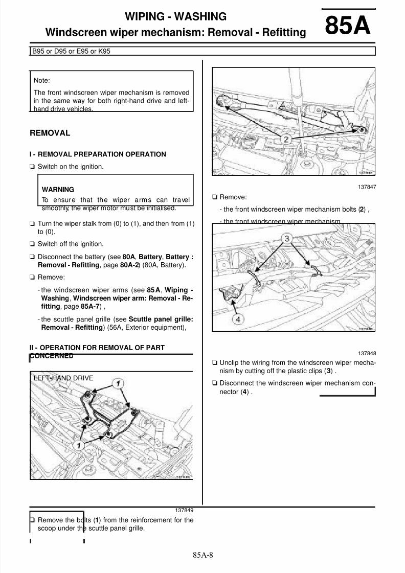
8/6/2019 8 - Electrical Equipment
http://slidepdf.com/reader/full/8-electrical-equipment 124/29485A-8
WIPING - WASHING
Windscreen wiper mechanism: Removal - Refitting
B95 or D95 or E95 or K95
85A
REMOVAL
I - REMOVAL PREPARATION OPERATION
a Switch on the ignition.
a Turn the wiper stalk from (0) to (1), and then from (1)to (0).
a Switch off the ignition.
a Disconnect the battery (see 80A, Battery, Battery :Removal - Refitting, page 80A-2) (80A, Battery).
a Remove:
- the windscreen wiper arms (see 85A, Wiping -
Washing, Windscreen wiper arm: Removal - Re-fitting, page 85A-7) ,
- the scuttle panel grille (see Scuttle panel grille:Removal - Refitting) (56A, Exterior equipment),
II - OPERATION FOR REMOVAL OF PARTCONCERNED
a Remove the bolts (1) from the reinforcement for thescoop under the scuttle panel grille.
a Remove:
- the front windscreen wiper mechanism bolts (2) ,
- the front windscreen wiper mechanism.
a Unclip the wiring from the windscreen wiper mecha-nism by cutting off the plastic clips ( 3) .
a Disconnect the windscreen wiper mechanism con-
nector (4) .
Note:
The front windscreen wiper mechanism is removed
in the same way for both right-hand drive and left-hand drive vehicles.
WARNING
To ensure that the wiper arms can travelsmoothly, the wiper motor must be initialised.
LEFT-HAND DRIVE
137849
137847
137848

8/6/2019 8 - Electrical Equipment
http://slidepdf.com/reader/full/8-electrical-equipment 125/29485A-9
WIPING - WASHING
Windscreen wiper mechanism: Removal - Refitting
B95 or D95 or E95 or K95
85A
a Remove the bolts (5) from the reinforcement for thescoop under the scuttle panel grille.
a Disconnect the windscreen wiper mechanism con-nector (6) .
a Remove:
- the front windscreen wiper mechanism bolts (7) ,
- the front windscreen wiper mechanism.
REFITTING
I - REFITTING OPERATION FOR PARTCONCERNED
a Refit the windscreen wiper mechanism.
a Connect the windscreen wiper mechanism connec-tor.
a Clip on the wiring using plastic clips.
a Refit the reinforcement for the scoop under the scu-
ttle panel grille.
II - FINAL OPERATION
a Refit the scuttle panel grille (see Scuttle panelgrille: Removal - Refitting) (56A, Exterior equip-ment).
a Connect the battery (see 80A, Battery, Battery :Removal - Refitting, page 80A-2) (80A, Battery).
a Switch on the ignition.
a Turn the wiper stalk from (0) to (1), and then from (1)to (0).
a Switch off the ignition.
a Refit the windscreen wiper arms (see 85A, Wiping -Washing, Windscreen wiper arm: Removal - Re-fitting, page 85A-7) .
RIGHT-HAND DRIVE
137851
137850
LEFT-HAND DRIVE
WARNING
To ensure that the wiper arms can travelsmoothly, the wiper motor must be initialised.

8/6/2019 8 - Electrical Equipment
http://slidepdf.com/reader/full/8-electrical-equipment 126/294

8/6/2019 8 - Electrical Equipment
http://slidepdf.com/reader/full/8-electrical-equipment 127/29485A-11
WIPING - WASHING
Rear screen wiper blade: Removal - Refitting
J95
85A
REMOVAL
OPERATION FOR REMOVAL OF PARTCONCERNED
a Lift the rear screen wiper arm (2) .
a Pivot (A) the rear screen wiper blade (1) .
a Unclip (B) the rear screen wiper blade (1) from therear screen wiper arm (2) .
REFITTING
REFITTING OPERATION FOR PART CONCERNED
a Clip the rear screen wiper blade onto the rear screenwiper arm.
a Lower the rear screen wiper arm onto the rear
screen.
100000-1

8/6/2019 8 - Electrical Equipment
http://slidepdf.com/reader/full/8-electrical-equipment 128/29485A-12
WIPING - WASHING
Rear screen wiper arm: Removal - Refitting
B95 or D95
85A
REMOVAL
I - REMOVAL PREPARATION OPERATION
aSwitch on the ignition.
a Turn the wiper stalk from (0) to (1), and then from (1)to (0).
a Switch off the ignition.
a Visually mark the position of the rear screen wiperarm for the refitting operation.
II - OPERATION FOR REMOVAL OF PARTCONCERNED
a Open the nut cover (1) .
a Remove the nut (2) from the wiper arm.
a Remove the rear screen wiper arm using a 2-clawextractor (3) .
REFITTING
REFITTING OPERATION FOR PART CONCERNED
a Refit:
- the rear screen wiper arm in the position markedbefore the removal operation,
WARNING
To ensure that the wiper arms can travelsmoothly, the wiper motor must be initialised.
137843
137842
137841

8/6/2019 8 - Electrical Equipment
http://slidepdf.com/reader/full/8-electrical-equipment 129/29485A-13
WIPING - WASHING
Rear screen wiper arm: Removal - Refitting
B95 or D95
85A
- the rear screen wiper arm nut.
a Close the rear screen wiper arm nut cover.

8/6/2019 8 - Electrical Equipment
http://slidepdf.com/reader/full/8-electrical-equipment 130/29485A-14
WIPING - WASHING
Rear screen wiper motor: Removal - Refitting
B95 or D95
85A
REMOVAL
I - REMOVAL PREPARATION OPERATION
a Switch on the ignition.
a Turn the wiper stalk from (0) to (1), and then from (1)to (0).
a Switch off the ignition.
a Remove:
- the rear screen wiper arm (see 85A, Wiping -Washing, Rear screen wiper arm: Removal - Re-fitting, page 85A-12) ,
- the tailgate trim (see Tailgate lining: Removal -Refitting) (73A, Non-side opening elements trim).
II - OPERATION FOR REMOVAL OF PART
CONCERNED
a Disconnect the rear screen wiper motor connector
(1) .
a Remove the rivets (2) from the rear screen wipermotor (see MR 400).
REFITTING
I - REFITTING PREPARATION OPERATION
aSwitch on the ignition.
a Turn the wiper stalk from (0) to (1), and then from (1)to (0).
a Switch off the ignition.
II - REFITTING OPERATION FOR PART
CONCERNED
a Refit:
- the rear screen wiper motor,
- new rivets to the rear screen wiper motor (see MR
400).
a Connect the rear screen wiper motor connector.
III - FINAL OPERATION
a Refit:
- the tailgate trim (see Tailgate lining: Removal -Refitting) (73A, Non-side opening elements trim),
- the rear screen wiper arm (see 85A, Wiping -Washing, Rear screen wiper arm: Removal - Re-fitting, page 85A-12) .
WARNING
To ensure that the wiper arms can travelsmoothly, the wiper motor must be initialised.
137844
WARNING
To ensure that the wiper arms can travelsmoothly, the wiper motor must be initialised.

8/6/2019 8 - Electrical Equipment
http://slidepdf.com/reader/full/8-electrical-equipment 131/29485A-15
WIPING - WASHING
Rain and light sensor: Removal - Refitting
AUTO LIGHTS+WIPER
85A
REMOVAL
I - REMOVAL PREPARATION OPERATION
a Switch off the ignition.
a Unclip the covers under the door mirror using the(Car. 1363).
a Disconnect the connectors.
II - OPERATION FOR REMOVAL OF PARTCONCERNED
1 - Replacing the rain and light sensor
a Disconnect the rain and light sensor connector (1) .
a Unclip the two side clips (2) from the rain and lightsensor using the (Car. 1363),
a Remove the rain and light sensor.
2 - Replace the windscreen
a
a Disconnect the rain and light sensor connector.
Essential special tooling
Car. 1363 Set of trim removal levers.
Essential equipment
diagnostic tool
Note:
The rain and light sensor also controls the solarradiation function depending on the vehicle equip-ment level.
126307
101630
Note:
A mounting base for the rain and light sensor issupplied with the new windscreen.
Note:
After the rain and light sensor has been remo-ved, do not reuse the old adhesive base. Use anew adhesive base.

8/6/2019 8 - Electrical Equipment
http://slidepdf.com/reader/full/8-electrical-equipment 132/29485A-16
WIPING - WASHING
Rain and light sensor: Removal - Refitting
AUTO LIGHTS+WIPER
85A
a Unclip the side clips (3) of the rain and light sensorfrom the base of the windscreen, using the tool (Car.1363).
a Unclip the rain and light sensor's printed circuit unitby pressing on the clips (4) using a small flat-bladescrewdriver.
a Remove the rain and light sensor's printed circuitunit.
REFITTING
I - REFITTING PREPARATION OPERATION
a
101630
102446
124344
WARNING
The rain sensor should be removed and refittedin totally clean conditions: any dust or cloth resi-due could cause a malfunction.
Do not touch the electronic part of the sensor. Fitthe sensor to the vehicle immediately after remo-ving it from its packaging.
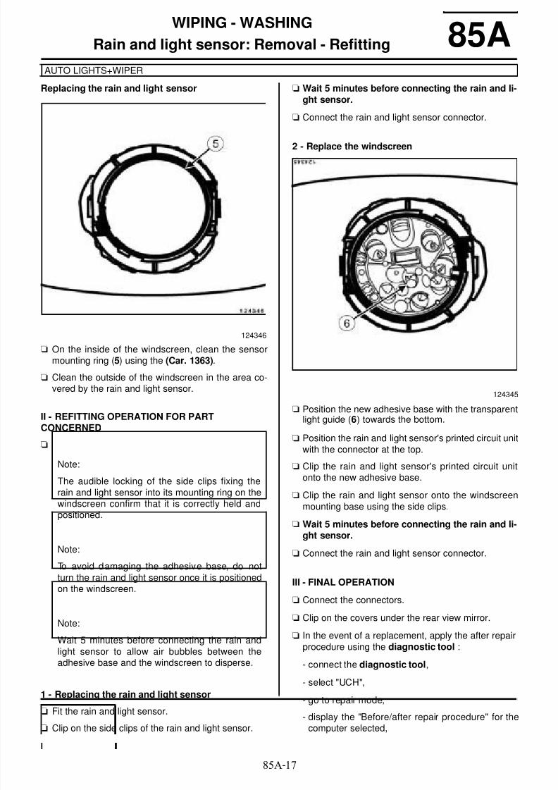
8/6/2019 8 - Electrical Equipment
http://slidepdf.com/reader/full/8-electrical-equipment 133/29485A-17
WIPING - WASHING
Rain and light sensor: Removal - Refitting
AUTO LIGHTS+WIPER
85A
Replacing the rain and light sensor
a On the inside of the windscreen, clean the sensormounting ring (5) using the (Car. 1363).
a Clean the outside of the windscreen in the area co-vered by the rain and light sensor.
II - REFITTING OPERATION FOR PARTCONCERNED
a
1 - Replacing the rain and light sensor
a Fit the rain and light sensor.
a Clip on the side clips of the rain and light sensor.
a Wait 5 minutes before connecting the rain and li-ght sensor.
a Connect the rain and light sensor connector.
2 - Replace the windscreen
a Position the new adhesive base with the transparentlight guide (6) towards the bottom.
a Position the rain and light sensor's printed circuit unitwith the connector at the top.
a Clip the rain and light sensor's printed circuit unitonto the new adhesive base.
a Clip the rain and light sensor onto the windscreenmounting base using the side clips.
a Wait 5 minutes before connecting the rain and li-ght sensor.
a Connect the rain and light sensor connector.
III - FINAL OPERATION
a Connect the connectors.
a Clip on the covers under the rear view mirror.
a In the event of a replacement, apply the after repairprocedure using the diagnostic tool :
- connect the diagnostic tool,
- select "UCH",
- go to repair mode,
- display the "Before/after repair procedure" for thecomputer selected,
124346
Note:
The audible locking of the side clips fixing therain and light sensor into its mounting ring on thewindscreen confirm that it is correctly held andpositioned.
Note:To avoid damaging the adhesive base, do notturn the rain and light sensor once it is positionedon the windscreen.
Note:
Wait 5 minutes before connecting the rain andlight sensor to allow air bubbles between theadhesive base and the windscreen to disperse.
124345

8/6/2019 8 - Electrical Equipment
http://slidepdf.com/reader/full/8-electrical-equipment 134/29485A-18
WIPING - WASHING
Rain and light sensor: Removal - Refitting
AUTO LIGHTS+WIPER
85A
- select "Rain and light sensor" in the "List of compo-nents stored by this computer" section,
- carry out the operations described in the "After re-pair procedure" section.
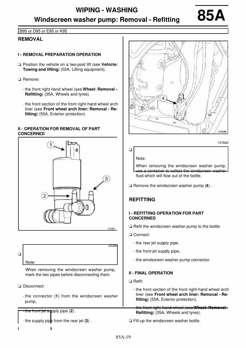
8/6/2019 8 - Electrical Equipment
http://slidepdf.com/reader/full/8-electrical-equipment 135/29485A-19
WIPING - WASHING
Windscreen washer pump: Removal - Refitting
B95 or D95 or E95 or K95
85A
REMOVAL
I - REMOVAL PREPARATION OPERATION
a Position the vehicle on a two-post lift (see Vehicle:Towing and lifting) (02A, Lifting equipment).
a Remove:
- the front right-hand wheel (see Wheel: Removal -Refitting) (35A, Wheels and tyres),
- the front section of the front right-hand wheel archliner (see Front wheel arch liner: Removal - Re-fitting) (55A, Exterior protection).
II - OPERATION FOR REMOVAL OF PARTCONCERNED
a
a Disconnect:
- the connector (1) from the windscreen washer
pump,
- the front jet supply pipe (2) ,
- the supply pipe from the rear jet (3) .
a
a Remove the windscreen washer pump (4) .
REFITTING
I - REFITTING OPERATION FOR PARTCONCERNED
a Refit the windscreen washer pump to the bottle.
a Connect:
- the rear jet supply pipe,
- the front jet supply pipe,
- the windscreen washer pump connector.
II - FINAL OPERATION
a Refit:
- the front section of the front right-hand wheel archliner (see Front wheel arch liner: Removal - Re-fitting) (55A, Exterior protection),
- the front right-hand wheel (see Wheel: Removal -Refitting) (35A, Wheels and tyres).
a Fill-up the windscreen washer bottle.
20389
Note:
When removing the windscreen washer pump,mark the two pipes before disconnecting them.
137845
Note:
When removing the windscreen washer pump,use a container to collect the windscreen washerfluid which will flow out of the bottle.

8/6/2019 8 - Electrical Equipment
http://slidepdf.com/reader/full/8-electrical-equipment 136/29485A-20
WIPING - WASHING
Headlight washer pump: Removal - Refitting
B95 or D95 or E95 or K95, and HEADLIGHT WASHERS WITH BLADE
85A
REMOVAL
I - REMOVAL PREPARATION OPERATION
aPosition the vehicle on a two-post lift (see Vehicle:Towing and lifting) (02A, Lifting equipment).
a Remove:
- the front wheels (see Wheel: Removal - Refitting)(35A, Wheels and tyres),
- the front wheel arch liners (see Front wheel archliner: Removal - Refitting) (55A, Exterior protec-tion),
- the front bumper (see Front bumper: Removal -Refitting) (55A, Exterior protection).
II - OPERATION FOR REMOVAL OF PARTCONCERNED
a Disconnect the connector (1) from the headlightwasher pump.
a Unclip the pipes (2) from the headlight washerpump.
a Remove the headlight washer pump.
REFITTING
I - REFITTING OPERATION FOR PARTCONCERNED
a Refit the headlight washer pump to the bottle.
137835
Note:
Mark the headlight washer pump pipes beforeremoval to avoid inverting them during refitting.
Note:
When removing the headlight washer pump,have a container ready for the flow of windscreenwasher fluid from the bottle.

8/6/2019 8 - Electrical Equipment
http://slidepdf.com/reader/full/8-electrical-equipment 137/29485A-21
WIPING - WASHING
Headlight washer pump: Removal - Refitting
B95 or D95 or E95 or K95, and HEADLIGHT WASHERS WITH BLADE
85A
a Clip the pipes (3) onto the headlight washer pump.
a Connect the headlight washer pump connector.
II - FINAL OPERATION
a Refit:
- the front bumper (see Front bumper: Removal -Refitting) (55A, Exterior protection),
- the front wheel arch liners (see Front wheel archliner: Removal - Refitting) (55A, Exterior protec-tion),
- the front wheels (see Wheel: Removal - Refitting)(35A, Wheels and tyres).
a Fill-up the windscreen washer bottle.
20389

8/6/2019 8 - Electrical Equipment
http://slidepdf.com/reader/full/8-electrical-equipment 138/294

8/6/2019 8 - Electrical Equipment
http://slidepdf.com/reader/full/8-electrical-equipment 139/29485A-23
WIPING - WASHING
Rear screen washer jet: Removal - Refitting
B95 or D95 or E95 or K95
85A
REMOVAL
I - REMOVAL PREPARATION OPERATION
aRemove the high level brake light (see 81A, Rear li-ghting, Third brake light: Removal - Refitting,page 81A-11) .
II - OPERATION FOR REMOVAL OF PARTCONCERNED
a Unclip the rear screen washer jet by pressing on theclips (1) using a small flat-blade screwdriver.
REFITTING
I - REFITTING OPERATION FOR PARTCONCERNED
a Clip the rear screen washer jet on the high level bra-ke light.
II - FINAL OPERATION
a Refit the high level brake light (see 81A , Rear li-ghting, Third brake light: Removal - Refitting,page 81A-11) .
137854

8/6/2019 8 - Electrical Equipment
http://slidepdf.com/reader/full/8-electrical-equipment 140/29485A-24
WIPING - WASHING
Windscreen washer bottle: Removal - Refitting
B95 or D95 or E95 or K95
85A
REMOVAL
I - REMOVAL PREPARATION OPERATION
aPosition the vehicle on a two-post lift (see Vehicle:Towing and lifting) (02A, Lifting equipment).
a Remove:
- the front wheels (see Wheel: Removal - Refitting)(35A, Wheels and tyres),
- the front wheel arch liners (see Front wheel archliner: Removal - Refitting) (55A, Exterior protec-tion),
- the front bumper (see Front bumper: Removal -Refitting) (55A, Exterior protection),
- the right-hand headlight (see 80B, Headlights,Front headlight: Removal - Refitting, page 80B-4) ,
- the windscreen washer bottle neck (see 85A, Wi-ping - Washing, Windscreen washer bottle fun-nel: Removal - Refitting, page 85A-26) .
a Remove the windscreen washer pump (see 85A ,Wiping - Washing, Windscreen washer pump:Removal - Refitting, page 85A-19) .
a Remove the headlight washer pump (see 85A, Wi-ping - Washing, Headlight washer pump: Remo-val - Refitting, page 85A-20) .
II - OPERATION FOR REMOVAL OF PARTCONCERNED
a Remove:
- the bolt (1) from the windscreen washer bottle,
- the windscreen washer bottle.
REFITTING
I - REFITTING OPERATION FOR PARTCONCERNED
a Refit:
- the windscreen washer bottle,
- the windscreen washer bottle bolt.
II - FINAL OPERATION
a Refit the headlight washer pump (see 85A, Wiping -Washing, Headlight washer pump: Removal -Refitting, page 85A-20) .
a Refit:
- the windscreen washer pump (see 85A, Wiping -Washing, Windscreen washer pump: Removal -Refitting, page 85A-19) ,
Note:
When removing the windscreen washer pump,use a container to collect the windscreen washerfluid which will flow out of the bottle.
HEADLIGHT WASHERS WITH BLADE
137837
HEADLIGHT WASHERS WITH BLADE

8/6/2019 8 - Electrical Equipment
http://slidepdf.com/reader/full/8-electrical-equipment 141/29485A-25
WIPING - WASHING
Windscreen washer bottle: Removal - Refitting
B95 or D95 or E95 or K95
85A
- the windscreen washer bottle neck (see 85A, Wi-ping - Washing, Windscreen washer bottle fun-nel: Removal - Refitting, page 85A-26) .
- the right-hand headlight (see 80 B, Headlights,
Front headlight: Removal - Refitting, page 80B-4) ,
- the front bumper (see Front bumper: Removal -Refitting) (55A, Exterior protection),
- the front wheel arch liners (see Front wheel archliner: Removal - Refitting) (55A, Exterior protec-tion),
- the front wheels (see Wheel: Removal - Refitting)
(35A, Wheels and tyres).
a Fill-up the windscreen washer bottle.

8/6/2019 8 - Electrical Equipment
http://slidepdf.com/reader/full/8-electrical-equipment 142/29485A-26
WIPING - WASHING
Windscreen washer bottle funnel: Removal - Refitting
B95 or D95 or E95 or K95
85A
REMOVAL
OPERATION FOR REMOVAL OF PARTCONCERNED
a Unclip the windscreen washer bottle neck at (1) .
a Remove the windscreen washer bottle neck.
REFITTING
REFITTING OPERATION FOR PART CONCERNED
a Refit the windscreen washer bottle neck.
137846

8/6/2019 8 - Electrical Equipment
http://slidepdf.com/reader/full/8-electrical-equipment 143/29486A-1
RADIO
Audio equipment: List and location of components 86AI - LIST OF COMPONENTS
The radio system comprises:
- a radio
- a radio aerial
- front speakers
- an offset multimedia socket
- a radio aerial amplifier
- tweeters
- a radio control satellite
- an offset multimedia socket computer
- a receiver
- a display
- rear speakers
II - LOCATION OF COMPONENTS
Radio
Radio aerial
The aerial is screen printed onto the rear screen.
To replace the aerial, the rear screen must be replaced(see Rear screen: Removal - Refitting) (54A, Win-dows).
RADIO NO 03 or RADIO NO 05 or RADIO NO 06or RADIO NO 07
RADIO NO 01 or RADIO NO 02 or RADIO NO 03or RADIO NO 04 or RADIO NO 05 or RADIO NO06 or RADIO NO 07
RADIO NO 04 or RADIO NO 05
RADIO NO 07
B95 or D95 or K95, and RADIO NO 01 or RADIONO 02 or RADIO NO 03 or RADIO NO 04 orRADIO NO 05 or VEHICLE WITHOUT RADIO
B95 or D95 or K95
136696
137340

8/6/2019 8 - Electrical Equipment
http://slidepdf.com/reader/full/8-electrical-equipment 144/29486A-2
RADIO
Audio equipment: List and location of components 86AFront speaker
Offset multimedia socket
Radio aerial amplifier
Front tweeter
136731
136701
RADIO NO 03 or RADIO NO 05 or RADIO NO 06or RADIO NO 07
135352
136699

8/6/2019 8 - Electrical Equipment
http://slidepdf.com/reader/full/8-electrical-equipment 145/29486A-3
RADIO
Audio equipment: List and location of components 86A
Rear tweeter Rear tweeter
B95 or K95
136730
D95
137446

8/6/2019 8 - Electrical Equipment
http://slidepdf.com/reader/full/8-electrical-equipment 146/29486A-4
RADIO
Audio equipment: List and location of components 86A
Radio control satellite
Offset multimedia socket computer
The offset multimedia socket computer is locatedbehind the glovebox above the passenger compart-ment fan assembly, regardless of the driver's position.
Receiver
The receiver is located behind the glovebox.
RADIO NO 01 or RADIO NO 02 or RADIO NO 03or RADIO NO 04 or RADIO NO 05 or RADIO NO06 or RADIO NO 07
136701
RADIO NO 04 or RADIO NO 05
138070
RADIO NO 07
137662

8/6/2019 8 - Electrical Equipment
http://slidepdf.com/reader/full/8-electrical-equipment 147/29486A-5
RADIO
Audio equipment: List and location of components 86A
Display
Rear speaker
Rear speaker
B95 or D95 or K95, and RADIO NO 01 or RADIONO 02 or RADIO NO 03 or RADIO NO 04 orRADIO NO 05 or VEHICLE WITHOUT RADIO
136701
B95 or K95
136730
D95
137446

8/6/2019 8 - Electrical Equipment
http://slidepdf.com/reader/full/8-electrical-equipment 148/29486A-6
RADIO
Car radio: Removal - Refitting 86A
REMOVAL
I - REMOVAL PREPARATION OPERATION
a Switch off the ignition.
a Remove the centre front panel (see Centre frontpanel: Removal - Refitting) (57A, Interior equip-ment).
II - OPERATION FOR REMOVAL OF PARTCONCERNED
a Remove the radio using two (Ms. 1821) (1) .
a Disconnect the audio equipment connectors.
a
a Disconnect the aerial.
REFITTING
I - REFITTING OPERATION FOR PARTCONCERNED
a
a Connect the aerial.
Essential special tooling
Ms. 1821 Radio removal tool (4-hole)
Essential equipment
diagnostic tool
136696
RADIO NO 01 or RADIO NO 02 or RADIO NO 03or RADIO NO 04 or RADIO NO 05 or RADIO NO06
WARNING
To ensure correct operation:
- do not pinch the aerial cable,
- do not bend the aerial cable,
- do not force the aerial cable when refitting.
RADIO NO 01 or RADIO NO 02 or RADIO NO 03or RADIO NO 04 or RADIO NO 05 or RADIO NO06
WARNING
To ensure correct operation:
- do not pinch the aerial cable,
- do not bend the aerial cable,
- do not force the aerial cable when refitting.

8/6/2019 8 - Electrical Equipment
http://slidepdf.com/reader/full/8-electrical-equipment 149/29486A-7
RADIO
Car radio: Removal - Refitting 86A
a Clip on the aerial wiring at (2) .
a Connect the radio connectors.
a Refit the radio.
II - FINAL OPERATION
a Refit the centre front panel (see Centre front panel:Removal - Refitting) (57A, Interior equipment).
a In the event of a replacement, apply the after repair
procedure using the diagnostic tool :
- connect the diagnostic tool,
- select "Car phone",
- go to repair mode,
- display the "Before/After repair procedure" for theselected computer,
- select "Radio" in the "List of components controlledby this computer" section,
- carry out the operations described in the "After re-
pair procedure" section.
137303
RADIO NO 01 or RADIO NO 02 or RADIO NO 03or RADIO NO 04 or RADIO NO 05

8/6/2019 8 - Electrical Equipment
http://slidepdf.com/reader/full/8-electrical-equipment 150/29486A-8
RADIO
Tuner-amplifier: Removal - Refitting
RADIO NO 07
86A
REMOVAL
I - REMOVAL PREPARATION OPERATION
a Switch off the ignition.
a Remove the glovebox (see Glovebox: Removal -Refitting) (57A, Interior equipment).
II - OPERATION FOR REMOVAL OF PARTCONCERNED
a Remove:
- the bolts (1) from the "receiver - navigation compu-ter" assembly mountings,
- the "receiver - navigation computer" assemblymountings.
a Disconnect the connectors from the receiver.
a Disconnect the aerial.
Essential special tooling
Ms. 1821 Radio removal tool (4-hole)
138068
138069
WARNING
To ensure correct operation:
- do not pinch the aerial cable,
- do not bend the aerial cable,
- do not force the aerial cable when refitting.

8/6/2019 8 - Electrical Equipment
http://slidepdf.com/reader/full/8-electrical-equipment 151/29486A-9
RADIO
Tuner-amplifier: Removal - Refitting
RADIO NO 07
86A
a Remove:
- the receiver from its mounting using the tool (Ms.1821) (2) ,
- the receiver.
REFITTING
I - REFITTING OPERATION FOR PARTCONCERNED
a Refit the receiver to its support.
a Connect:
- the aerial,
- the receiver connectors.
a Refit:
- the "receiver - navigation computer" assemblymountings,
- the bolts on the "receiver - navigation computer"assembly mountings.
II - FINAL OPERATION
a Refit the glovebox (see Glovebox: Removal - Refit-ting) (57A, Interior equipment).
137663
WARNING
To ensure correct operation:
- do not pinch the aerial cable,
- do not bend the aerial cable,
- do not force the aerial cable when refitting.

8/6/2019 8 - Electrical Equipment
http://slidepdf.com/reader/full/8-electrical-equipment 152/29486A-10
RADIO
Radio aerial: Removal - Refitting 86Aa The radio aerial cannot be separated from the rear
screen window. If the radio aerial malfunctions, re-place the rear screen window (see Rear screen:Removal - Refitting) (54A, Windows).

8/6/2019 8 - Electrical Equipment
http://slidepdf.com/reader/full/8-electrical-equipment 153/29486A-11
RADIO
Radio aerial amplifier: Removal - Refitting
RADIO NO 03 or RADIO NO 05 or RADIO NO 06 or RADIO NO 07
86A
REMOVAL
I - REMOVAL PREPARATION OPERATION
aSwitch off the ignition.
a Unclip the tailgate upper trim (1) .
II - OPERATION FOR REMOVAL OF PARTCONCERNED
a Unclip:
- the aerial amplifier connector (2) from the window,
- the aerial amplifier connector (3) .
a Remove:
- the aerial amplifier nut (4) ,
- the aerial amplifier.
REFITTING
I - REFITTING OPERATION FOR PARTCONCERNED
a Refit the aerial amplifier.
a Connect the connectors.
II - FINAL OPERATION
a Clip on the tailgate upper trim.
135356
135352

8/6/2019 8 - Electrical Equipment
http://slidepdf.com/reader/full/8-electrical-equipment 154/29486A-12
RADIO
Tweeter: Removal - Refitting
RADIO NO 03 or RADIO NO 05 or RADIO NO 06 or RADIO NO 07
86A
REMOVAL
REMOVAL PREPARATION OPERATION
a Switch off the ignition.
Rear tweeter
a Remove the rear side door trim (see Rear side door
trim: Removal - Refitting) (72A, Side opening ele-ment trim).
a Remove:
- the door sill lining (see Door sill lining: Removal -Refitting) (71A, Body internal trim),
- the rear roof drip moulding trim (see Rear roof dripmoulding lining: Removal - Refitting) (71A,Body internal trim),
- the rear panel trim (see Rear panel trim: Removal- Refitting) (71A, Body internal trim).
OPERATION FOR REMOVAL OF PARTCONCERNED
1 - Front tweeter
a Unclip the tweeter grille using the tool (Car. 1363)
(1) .
a Unclip the tweeter using the tool (Car. 1363).
a Disconnect the tweeter connector.
a Remove the tweeter.
Essential special tooling
Car. 1363 Set of trim removal levers.
B95 or K95
D95
137665
137666

8/6/2019 8 - Electrical Equipment
http://slidepdf.com/reader/full/8-electrical-equipment 155/29486A-13
RADIO
Tweeter: Removal - Refitting
RADIO NO 03 or RADIO NO 05 or RADIO NO 06 or RADIO NO 07
86A
2 - Rear tweeter
a Turn the tweeter a quarter of a turn anti-clockwise(2) .
a Remove the tweeter.
REFITTING
I - REFITTING OPERATION FOR PARTCONCERNED
1 - Front tweeter
a Connect the tweeter connector.
a Clip:
- the tweeter onto the dashboard,
- the tweeter grille.
2 - Rear tweeter
a Refit the tweeter on the rear side door trim.
a Turn the tweeter a quarter of a turn clockwise.
II - FINAL OPERATION
Rear tweeter
a Refit the rear side door trim (see Rear side doortrim: Removal - Refitting) (72A, Side opening ele-ment trim).
a Refit:
- the rear panel trim (see Rear panel trim: Removal- Refitting) (71A, Body internal trim),
- the rear roof drip moulding trim (see Rear roof dripmoulding lining: Removal - Refitting) (71A,Body internal trim),
- the door sill lining (see Door sill lining: Removal -Refitting) (71A, Body internal trim).
125125
B95 or K95
D95

8/6/2019 8 - Electrical Equipment
http://slidepdf.com/reader/full/8-electrical-equipment 156/29486A-14
RADIO
Front speakers: Removal - Refitting 86AREMOVAL
I - REMOVAL PREPARATION OPERATION
a Switch off the ignition.
a Remove the front side door trim (see Front sidedoor trim: Removal - Refitting) (72A, Side openingelements trim).
II - OPERATION FOR REMOVAL OF PARTCONCERNED
a Disconnect the connector (1) .
a Remove:
- the rivets (2) (see MR 400),
- the front speaker.
REFITTING
I - REFITTING PREPARATION OPERATION
a Always replace the front speaker rivets.
II - REFITTING OPERATION FOR PARTCONCERNED
a Refit:
- the front speaker,
- new front speaker rivets (see MR 400).
a Connect the front speaker connector.
III - FINAL OPERATION
a Refit the front side door trim (see Front side doortrim: Removal - Refitting) (72A, Side opening ele-ments trim).
125124

8/6/2019 8 - Electrical Equipment
http://slidepdf.com/reader/full/8-electrical-equipment 157/29486A-15
RADIO
Rear speakers: Removal - Refitting
B95 or K95
86A
REMOVAL
I - REMOVAL PREPARATION OPERATION
a Switch off the ignition.
a Remove the rear side door trim (see Rear side doortrim: Removal - Refitting) (72A, Side opening ele-ment trim).
II - OPERATION FOR REMOVAL OF PARTCONCERNED
a Disconnect the rear speaker connector (1) .
a Remove:
- the rear speaker rivets (2) (see MR 400),
- the rear speaker.
REFITTING
I - REFITTING PREPARATION OPERATION
a Always replace the rear speaker rivets.
II - REFITTING OPERATION FOR PARTCONCERNED
a Refit:
- the rear speaker,
- new rear speaker rivets (see MR 400).
a Connect the rear speaker connector.
III - FINAL OPERATION
a Refit the rear side door trim (see Rear side doortrim: Removal - Refitting) (72A, Side opening ele-ment trim).
137658

8/6/2019 8 - Electrical Equipment
http://slidepdf.com/reader/full/8-electrical-equipment 158/29486A-16
RADIO
Rear speakers: Removal - Refitting
D95
86A
REMOVAL
I - REMOVAL PREPARATION OPERATION
a Switch off the ignition.
a Remove:
- the door sill lining (see Door sill lining: Removal -Refitting) (71A, Body internal trim),
- the rear roof drip moulding trim (see Rear roof dripmoulding lining: Removal - Refitting) (71A,Body internal trim),
- the rear panel trim (see Rear panel trim: Removal- Refitting) (71A, Body internal trim).
II - OPERATION FOR REMOVAL OF PARTCONCERNED
a Disconnect the rear speaker connector (1) .
a Remove:
- the rear speaker rivets (2) (see MR 400),
- the rear speaker.
REFITTING
I - REFITTING PREPARATION OPERATION
a Always replace the rear speaker rivets.
II - REFITTING OPERATION FOR PARTCONCERNED
a Refit:
- the rear speaker,- new rear speaker rivets (see MR 400).
a Connect the rear speaker connector.
III - FINAL OPERATION
a Refit:
- the rear panel trim (see Rear panel trim: Removal- Refitting) (71A, Body internal trim),
- the rear roof drip moulding trim (see Rear roof dripmoulding lining: Removal - Refitting) (71A,
Body internal trim),
- the door sill lining (see Door sill lining: Removal -Refitting) (71A, Body internal trim).
134379

8/6/2019 8 - Electrical Equipment
http://slidepdf.com/reader/full/8-electrical-equipment 159/29486A-17
RADIO
Display: Removal - Refitting
B95 or D95 or K95, and WITHOUT NAVIGATION AID, and RADIO NO 01 or RADIO NO 02 or RADIO NO 03 orRADIO NO 04 or RADIO NO 05 or VEHICLE WITHOUT RADIO
86A
REMOVAL
I - REMOVAL PREPARATION OPERATION
a Switch off the ignition.
a Unclip the "mounting - display" assembly using thetool (Car. 1363).
a Disconnect the display connector.
II - OPERATION FOR REMOVAL OF PARTCONCERNED
a Unclip the display from its mounting at (1) .
REFITTING
I - REFITTING OPERATION FOR PARTCONCERNED
a Clip the display onto its mounting.
II - FINAL OPERATION
a Connect the connector to the display.
a Clip the "mounting - display" assembly onto the das-
hboard.a Apply the before repair procedure using the dia-
gnostic tool :
- connect the diagnostic tool,
- select "Radio display",
- go to repair mode,
- display "Before/After repair procedure" in the se-lected computer,
- select "Radio display" in the "List of componentscontrolled by this computer" section,
- carry out the operations described in the "After re-pair procedure" section.
Essential special tooling
Car. 1363 Set of trim removal levers.
Essential equipment
diagnostic tool
136708
136710

8/6/2019 8 - Electrical Equipment
http://slidepdf.com/reader/full/8-electrical-equipment 160/29486A-18
RADIO
Radio control satellite: Removal - Refitting
RADIO NO 01 or RADIO NO 02 or RADIO NO 03 or RADIO NO 04 or RADIO NO 05 or RADIO NO 06 or RADIONO 07
86A
REMOVAL
I - REMOVAL PREPARATION OPERATION
a Switch off the ignition.
a Remove the bolts (1) from the shells under the stee-
ring wheel.
a Put the steering column into the lower position.
a Remove the upper cover.
a Place the steering column in the upper position.
a Remove the lower cover.
II - OPERATION FOR REMOVAL OF PARTCONCERNED
a
a Remove the radio control satellite bolt (2) .
a Unclip the radio control satellite at (3) .
a Disconnect the radio control satellite connector.
REFITTING
I - REFITTING OPERATION FOR PART
CONCERNED
a Connect the radio control satellite connector.
a Clip the radio control satellite onto the steering colu-
mn switch assembly.
a Refit the radio control satellite bolt.
II - FINAL OPERATION
a Place the steering column in the upper position.
a Refit the lower cover.
a Put the steering column into the lower position.
a Refit:
- the upper cover,
- the bolts to the covers under the steering wheel.
136716
Note:
The steering column switch assembly does notneed to be removed.
137956
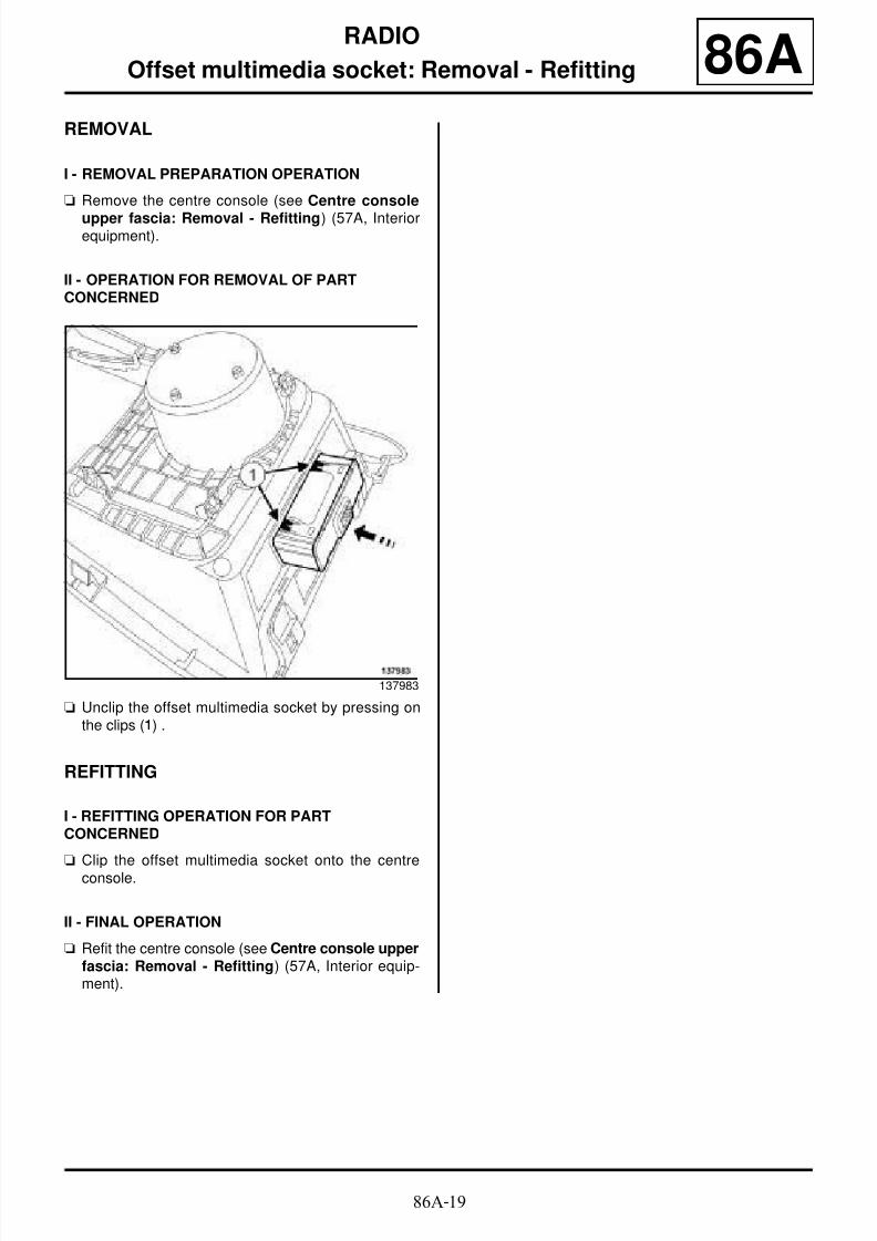
8/6/2019 8 - Electrical Equipment
http://slidepdf.com/reader/full/8-electrical-equipment 161/29486A-19
RADIO
Offset multimedia socket: Removal - Refitting 86AREMOVAL
I - REMOVAL PREPARATION OPERATION
a Remove the centre console (see Centre console
upper fascia: Removal - Refitting) (57A, Interiorequipment).
II - OPERATION FOR REMOVAL OF PARTCONCERNED
a Unclip the offset multimedia socket by pressing onthe clips (1) .
REFITTING
I - REFITTING OPERATION FOR PARTCONCERNED
a Clip the offset multimedia socket onto the centreconsole.
II - FINAL OPERATION
a Refit the centre console (see Centre console upperfascia: Removal - Refitting) (57A, Interior equip-ment).
137983

8/6/2019 8 - Electrical Equipment
http://slidepdf.com/reader/full/8-electrical-equipment 162/29486A-20
RADIO
Offset multimedia socket computer: Removal - Refitting
RADIO NO 04 or RADIO NO 05
86A
REMOVAL
I - REMOVAL PREPARATION OPERATION
a Disconnect the battery (see 80A, Battery, Battery :Removal - Refitting, page 80A-2) .
a Remove the glovebox (see Glovebox: Removal -
Refitting) (57A, Interior equipment).
II - OPERATION FOR REMOVAL OF PARTCONCERNED
a Unclip the offset multimedia socket computer to-wards the rear (1) .
a Disconnect the offset multimedia socket computerconnectors.
a Remove the offset multimedia socket computer.
REFITTING
I - REFITTING OPERATION FOR PARTCONCERNED
a Connect the offset multimedia socket connectors.
a Clip the offset multimedia socket computer onto itsmounting.
II - FINAL OPERATION
a Refit the glovebox (see Glovebox: Removal - Refit-ting) (57A, Interior equipment).
a
Connect the battery (see Battery: Removal - Refit-ting) .
a Switch on the ignition.
a Apply the after repair procedure using the diagnos-tic tool :
- connect the diagnostic tool,
- select "Mobile connectivity computer",
- go to repair mode,
- display the "Before/after repair procedure" for thecomputer selected,
- carry out the operations described in the "After re-pair procedure" section.
Essential equipment
diagnostic tool
138070

8/6/2019 8 - Electrical Equipment
http://slidepdf.com/reader/full/8-electrical-equipment 163/29486B-1
CAR PHONE
Hands-free microphone: Removal - Refitting
RADIO NO 02 or RADIO NO 03 or RADIO NO 04 or RADIO NO 05 or RADIO NO 06 or RADIO NO 07
86B
REMOVAL
I - REMOVAL PREPARATION OPERATION
a Switch off the ignition.
a Remove the headlining (see Headlining: Removal -Refitting) (71A, Body internal trim).
a Unclip the sunroof switch trim at (1) using the tool(Car. 1363) .
a Unclip the sunroof switch trim at (2) using the tool(Car. 1363) .
a Disconnect the connectors.
Essential special tooling
Car. 1363 Set of trim removal levers.
NORMAL ROOF
137351
PANORAMIC SUNROOF
136961
136962
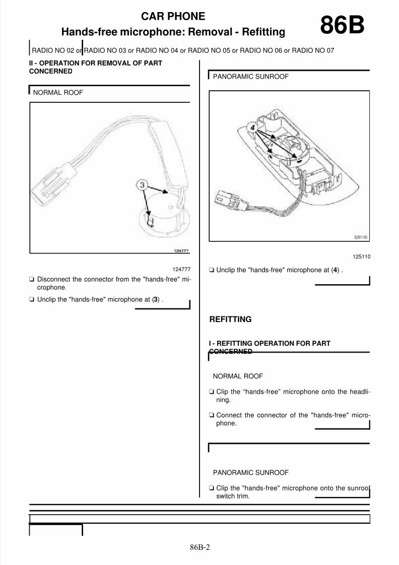
8/6/2019 8 - Electrical Equipment
http://slidepdf.com/reader/full/8-electrical-equipment 164/29486B-2
CAR PHONE
Hands-free microphone: Removal - Refitting
RADIO NO 02 or RADIO NO 03 or RADIO NO 04 or RADIO NO 05 or RADIO NO 06 or RADIO NO 07
86B
II - OPERATION FOR REMOVAL OF PARTCONCERNED
a Disconnect the connector from the "hands-free" mi-crophone.
a Unclip the "hands-free" microphone at (3) .
a Unclip the "hands-free" microphone at (4) .
REFITTING
I - REFITTING OPERATION FOR PARTCONCERNED
a Clip the “hands-free” microphone onto the headli-ning.
a Connect the connector of the "hands-free" micro-phone.
a Clip the "hands-free" microphone onto the sunroof
switch trim.
NORMAL ROOF
124777
PANORAMIC SUNROOF
125110
NORMAL ROOF
PANORAMIC SUNROOF

8/6/2019 8 - Electrical Equipment
http://slidepdf.com/reader/full/8-electrical-equipment 165/29486B-3
CAR PHONE
Hands-free microphone: Removal - Refitting
RADIO NO 02 or RADIO NO 03 or RADIO NO 04 or RADIO NO 05 or RADIO NO 06 or RADIO NO 07
86B
II - FINAL OPERATION
aRefit the headlining (see Headlining: Removal -Refitting) (71A, Body internal trim).
a Connect the connectors.
a Clip the sunroof switch trim onto the headlining.
NORMAL ROOF
PANORAMIC SUNROOF

8/6/2019 8 - Electrical Equipment
http://slidepdf.com/reader/full/8-electrical-equipment 166/29487B-1
PASSENGER COMPARTMENT CONNECTION UNIT
UCH: Removal - Refitting 87B
REMOVAL
I - REMOVAL PREPARATION OPERATION
a In the event of a replacement, apply the procedureusing the diagnostic tool :
- connect the diagnostic tool,
- select "UCH",
- go to repair mode,
- display the "Before/after repair procedure" for thecomputer selected,
- carry out the operations described in the "Beforerepair procedure" section.
a Switch off the ignition.
a Disconnect the battery (see 80A, Battery, Battery :Removal - Refitting, page 80A-2) .
a Remove the dashboard lower trim (1) (see Lowersection of dashboard trim: Removal - Refitting)(57A, Interior equipment).
a Remove the glovebox (2) (see Glovebox: Removal- Refitting) (57A, Interior equipment).
Essential equipment
diagnostic tool
WARNING
To avoid permanently locking the steering columnlock, never fit a UCH that has been previously usedon another vehicle.
LEFT-HAND DRIVE
137114
RIGHT-HAND DRIVE
137964

8/6/2019 8 - Electrical Equipment
http://slidepdf.com/reader/full/8-electrical-equipment 167/29487B-2
PASSENGER COMPARTMENT CONNECTION UNIT
UCH: Removal - Refitting 87BII - OPERATION FOR REMOVAL OF PARTCONCERNED
a
a Remove the bolt (3) from the UCH.
a Move aside the UCH at (4)
a Mark the wiring routing.
a Disconnect the UCH connectors.
a Remove the UCH.
WARNING
To avoid permanently locking the steeringcolumn lock, never fit a UCH that has been pre-viously used on another vehicle.
137957
137958
WARNING
To prevent any risk of noise, premature wear,short circuits, etc. after the refitting operation,
mark the wiring routing and how to connect theconnectors.

8/6/2019 8 - Electrical Equipment
http://slidepdf.com/reader/full/8-electrical-equipment 168/29487B-3
PASSENGER COMPARTMENT CONNECTION UNIT
UCH: Removal - Refitting 87BREFITTING
I - REFITTING OPERATION FOR PARTCONCERNED
a Connect:
- the 3 dashboard wiring connectors (5) on the UCH,
- the 3 connectors (6) of the left-hand A-pillar wiringon the UCH,
- the engine compartment wiring connector (7) onthe UCH,
a Fit the UCH.
a Refit the wiring in the positions noted during remo-val.
a Position the lugs (8) opposite their housing (8) .
a Refit the UCH by pushing at (9) .
137960
137960
137959

8/6/2019 8 - Electrical Equipment
http://slidepdf.com/reader/full/8-electrical-equipment 169/29487B-4
PASSENGER COMPARTMENT CONNECTION UNIT
UCH: Removal - Refitting 87B
a Secure the UCH on its support with the bolt (10) .
II - FINAL OPERATION
aRefit the dashboard lower trim (see Lower sectionof dashboard trim: Removal - Refitting) (57A, In-terior equipment).
a Refit the glovebox (see Glovebox: Removal - Refit-ting) (57A, Interior equipment).
a Connect the battery (see 80A, Battery, Battery :Removal - Refitting, page 80A-2) .
a In the event of a replacement, apply the after repairprocedure using the diagnostic tool :
- connect the diagnostic tool,
- select "UCH",
- go to repair mode,
- display the "Before/after repair procedure" for thecomputer selected,
- carry out the operations described in the "After re-pair procedure" section.
137957
LEFT-HAND DRIVE
RIGHT-HAND DRIVE

8/6/2019 8 - Electrical Equipment
http://slidepdf.com/reader/full/8-electrical-equipment 170/29487C-1
OPENING ELEMENT MANAGEMENT
Door management: List and location of components 87CI - LIST OF COMPONENTS
The opening elements management systemconsists of:
- a Renault card
- a tailgate opening switch
- a lock motor for the fuel filler flap
- opening aerials for the side opening elements integra-ted into the door handles
- a central door locking switch on the front left-handdoor handle
- an opening aerial for the non-side opening element
- a remote central door locking warning
II - LOCATION OF COMPONENTS
Renault Card
Tailgate opening switch
Lock motor for the fuel filler flap
The lock motor for the fuel filler flap is located behindthe rear right-hand wheel arch trim.
B95 or D95 or K95
DOOR OPEN SYST. 433 NML
125112
137661
B95 or D95 or K95
137790
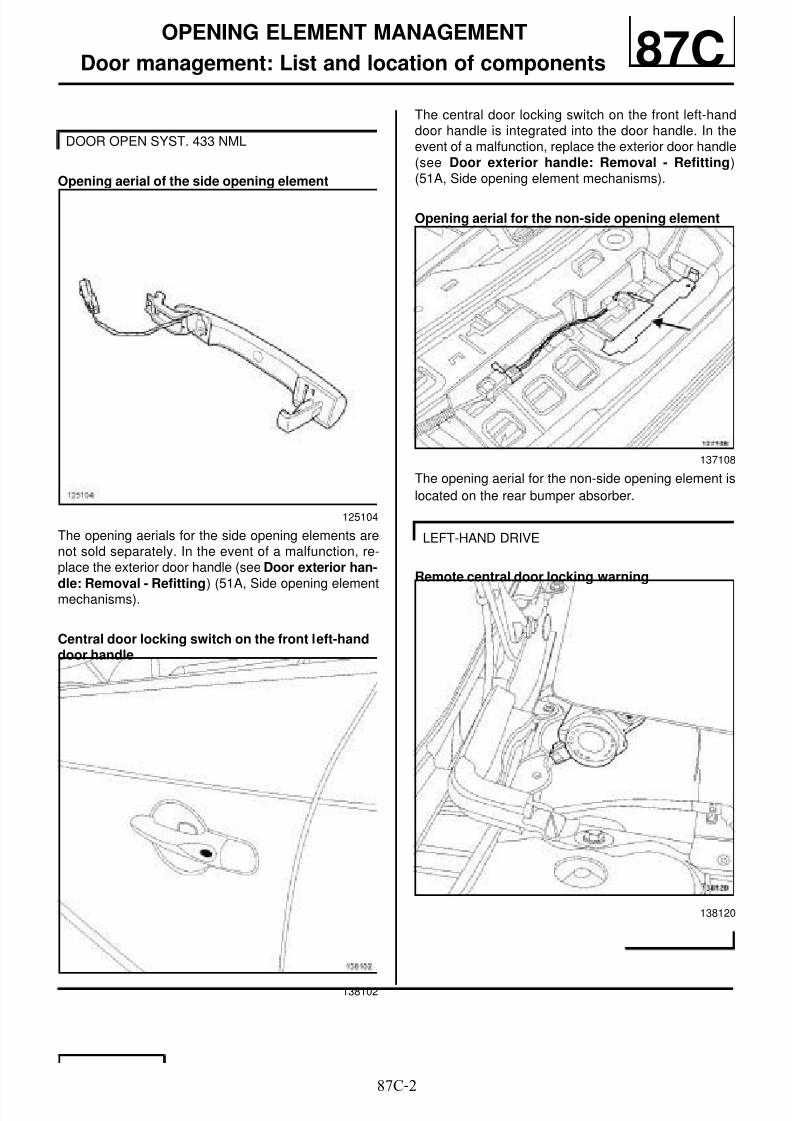
8/6/2019 8 - Electrical Equipment
http://slidepdf.com/reader/full/8-electrical-equipment 171/29487C-2
OPENING ELEMENT MANAGEMENT
Door management: List and location of components 87C
Opening aerial of the side opening element
The opening aerials for the side opening elements arenot sold separately. In the event of a malfunction, re-place the exterior door handle (see Door exterior han-
dle: Removal - Refitting) (51A, Side opening elementmechanisms).
Central door locking switch on the front left-handdoor handle
The central door locking switch on the front left-handdoor handle is integrated into the door handle. In theevent of a malfunction, replace the exterior door handle(see Door exterior handle: Removal - Refitting)(51A, Side opening element mechanisms).
Opening aerial for the non-side opening element
The opening aerial for the non-side opening element is
located on the rear bumper absorber.
Remote central door locking warning
DOOR OPEN SYST. 433 NML
125104
138102
137108
LEFT-HAND DRIVE
138120

8/6/2019 8 - Electrical Equipment
http://slidepdf.com/reader/full/8-electrical-equipment 172/29487C-3
OPENING ELEMENT MANAGEMENT
Door management: List and location of components 87C
Remote central door locking warning
RIGHT-HAND DRIVE
138119

8/6/2019 8 - Electrical Equipment
http://slidepdf.com/reader/full/8-electrical-equipment 173/29487C-4
OPENING ELEMENT MANAGEMENT
Opening aerial: Removal - Refitting
DOOR OPEN SYST. 433 NML
87C
REMOVAL
I - REMOVAL PREPARATION OPERATION
a Switch off the ignition.
a Position the vehicle on a two-post lift (see Vehicle:Towing and lifting) (02A, Lifting equipment).
a Remove:
- the rear wheels (see Wheel: Removal - Refitting)(35A, Wheel and tyres),
- the rear wheel arch liners (see Rear wheel archliner: Removal - Refitting) (55A, Exterior protec-tion),
- the rear lights on the wing (see 81A, Rear lighting,Rear light on wing: Removal - Refitting, page
81A-5) ,
- the rear bumper (see Rear bumper: Removal -Refitting) (55A, Exterior protection).
II - OPERATION FOR REMOVAL OF PARTCONCERNED
a Unclip the connector (1) from the opening aerial (2) .
a Disconnect the opening aerial connector.
a Unclip the opening aerial by pressing on the clip (3) .
REFITTING
I - REFITTING OPERATION FOR PARTCONCERNED
a Clip the opening aerial on to the rear absorber.
a Connect the opening aerial connector.
a Clip the opening aerial connector on to the rear ab-sorber.
II - FINAL OPERATION
a Refit:
- the rear bumper (see Rear bumper: Removal -
Refitting) (55A, Exterior protection),- the rear lights on the wing (see 81A, Rear lighting,
Rear light on wing: Removal - Refitting, page81A-5) ,
- the rear wheel arch liners (see Rear wheel archliner: Removal - Refitting) (55A, Exterior protec-tion),
- the rear wheels (see Wheel: Removal - Refitting)(35A, Wheel and tyres).
137108

8/6/2019 8 - Electrical Equipment
http://slidepdf.com/reader/full/8-electrical-equipment 174/29487C-5
OPENING ELEMENT MANAGEMENT
Tailgate opening switch: Removal - Refitting 87CREMOVAL
OPERATION FOR REMOVAL OF PARTCONCERNED
a Remove the tailgate opening switch using a smallflat-blade screwdriver while pressing on the clips (1).
a Disconnect the tailgate opening switch connector.
REFITTING
REFITTING OPERATION FOR PART CONCERNED
a Connect the tailgate opening switch connector.
a Clip the tailgate opening switch onto the luggagecompartment lid.
137660
101922

8/6/2019 8 - Electrical Equipment
http://slidepdf.com/reader/full/8-electrical-equipment 175/29487C-6
OPENING ELEMENT MANAGEMENT
Remote central door locking warning: Removal - Refitting
DOOR OPEN SYST. 433 NML
87C
REMOVAL
I - REMOVAL PREPARATION OPERATION
a Remove:
- the windscreen wiper arms (see 85A, Wiping -Washing, Windscreen wiper arm: Removal - Re-fitting, page 85A-7) (85A, Wiping - Washing),
- the scuttle panel grille (see Scuttle panel grille:Removal - Refitting) (56A, Exterior equipment).
II - OPERATION FOR REMOVAL OF PARTCONCERNED
a Disconnect the connector (1) from the remote cen-tral door locking warning.
a Remove:
- the bolt (2) of the remote central door locking war-ning,
- the remote central door locking warning.
REFITTING
I - REFITTING OPERATION FOR PARTCONCERNED
a Refit the remote central door locking warning.
a Connect the connector of the remote central doorlocking warning.
II - FINAL OPERATION
a Refit:
- the scuttle panel grille (see Scuttle panel grille:
Removal - Refitting) (56A, Exterior equipment),- the windscreen wiper arms (see 85A, Wiping -
Washing, Windscreen wiper arm: Removal - Re-fitting, page 85A-7) (85A, Wiping - Washing).
138120
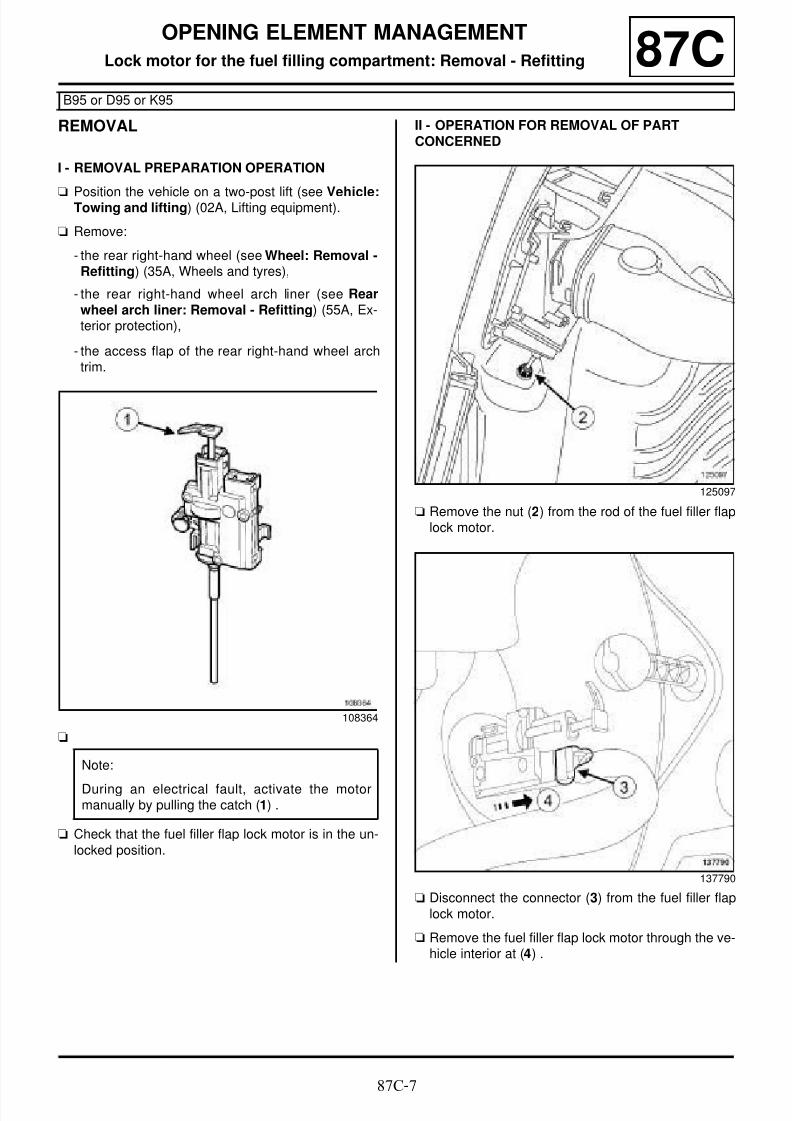
8/6/2019 8 - Electrical Equipment
http://slidepdf.com/reader/full/8-electrical-equipment 176/29487C-7
OPENING ELEMENT MANAGEMENT
Lock motor for the fuel filling compartment: Removal - Refitting
B95 or D95 or K95
87C
REMOVAL
I - REMOVAL PREPARATION OPERATION
aPosition the vehicle on a two-post lift (see Vehicle:Towing and lifting) (02A, Lifting equipment).
a Remove:
- the rear right-hand wheel (see Wheel: Removal -Refitting) (35A, Wheels and tyres),
- the rear right-hand wheel arch liner (see Rearwheel arch liner: Removal - Refitting) (55A, Ex-terior protection),
- the access flap of the rear right-hand wheel archtrim.
a
a Check that the fuel filler flap lock motor is in the un-locked position.
II - OPERATION FOR REMOVAL OF PARTCONCERNED
a Remove the nut (2) from the rod of the fuel filler flaplock motor.
a Disconnect the connector (3) from the fuel filler flaplock motor.
a Remove the fuel filler flap lock motor through the ve-hicle interior at (4) .
108364
Note:
During an electrical fault, activate the motormanually by pulling the catch (1) .
125097
137790

8/6/2019 8 - Electrical Equipment
http://slidepdf.com/reader/full/8-electrical-equipment 177/29487C-8
OPENING ELEMENT MANAGEMENT
Lock motor for the fuel filling compartment: Removal - Refitting
B95 or D95 or K95
87C
REFITTING
I - REFITTING OPERATION FOR PARTCONCERNED
a Refit the fuel filler flap lock motor.
a Connect the fuel filler flap lock motor connector.
II - FINAL OPERATION
a Refit:
- the access flap of the rear right-hand wheel archtrim,
- the rear right-hand wheel arch liner (see Rearwheel arch liner: Removal - Refitting) (55A, Ex-
terior protection),- the rear right-hand wheel (see Wheel: Removal -Refitting) (35A, Wheels and tyres).

8/6/2019 8 - Electrical Equipment
http://slidepdf.com/reader/full/8-electrical-equipment 178/29487D-1
ELECTRIC WINDOWS - SUNROOF
Electric window: List and location of components 87DI - LIST OF COMPONENTS
The electric window equipment consists of:
- electric window motors
- front electric window switches on the driver's door
- a front electric window switch on the passenger door
- rear electric window switches
- a child safety switch
II - LOCATION OF COMPONENTS
Front electric window motor
Rear electric window motor
Front electric window switches on the driver's door
B95 or J95 or K95, and REAR ELECTRIC WIN-DOW+ONE-TOUCH+ANTI-PINCH
137789
REAR ELECTRIC WINDOW+ONE-TOUCH+ANTI-PINCH
137659
124199
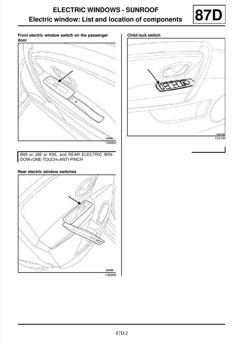
8/6/2019 8 - Electrical Equipment
http://slidepdf.com/reader/full/8-electrical-equipment 179/29487D-2
ELECTRIC WINDOWS - SUNROOF
Electric window: List and location of components 87DFront electric window switch on the passengerdoor
Rear electric window switches
Child lock switch
136963
B95 or J95 or K95, and REAR ELECTRIC WIN-DOW+ONE-TOUCH+ANTI-PINCH
136968
124199

8/6/2019 8 - Electrical Equipment
http://slidepdf.com/reader/full/8-electrical-equipment 180/29487D-3
ELECTRIC WINDOWS - SUNROOF
Electric sunroof: List and location of components
PANORAMIC SUNROOF
87D
I - LIST OF COMPONENTS
The electric sunroof equipment consists of:
- a sunroof switch
- an electric sunroof computer
- a sunroof opening motor
II - LOCATION OF COMPONENTS
Sunroof switch
Electric sunroof computer
Sunroof opening motor
135370
137656
137656
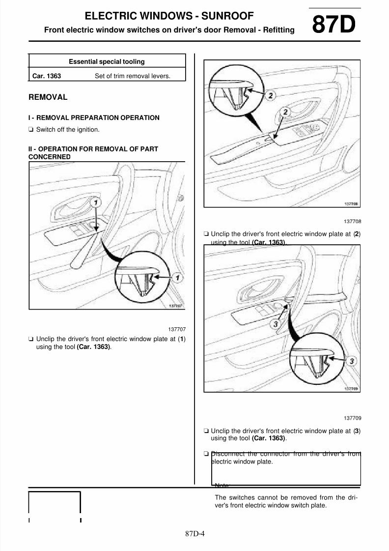
8/6/2019 8 - Electrical Equipment
http://slidepdf.com/reader/full/8-electrical-equipment 181/29487D-4
ELECTRIC WINDOWS - SUNROOF
Front electric window switches on driver's door Removal - Refitting 87D
REMOVAL
I - REMOVAL PREPARATION OPERATION
a Switch off the ignition.
II - OPERATION FOR REMOVAL OF PARTCONCERNED
a Unclip the driver's front electric window plate at (1)using the tool (Car. 1363).
a Unclip the driver's front electric window plate at (2)
using the tool (Car. 1363).
a Unclip the driver's front electric window plate at (3)using the tool (Car. 1363).
a Disconnect the connector from the driver's frontelectric window plate.
Essential special tooling
Car. 1363 Set of trim removal levers.
137707
137708
137709
Note:
The switches cannot be removed from the dri-ver's front electric window switch plate.

8/6/2019 8 - Electrical Equipment
http://slidepdf.com/reader/full/8-electrical-equipment 182/29487D-5
ELECTRIC WINDOWS - SUNROOF
Front electric window switches on driver's door Removal - Refitting 87DREFITTING
REFITTING OPERATION FOR PART CONCERNED
a Connect the driver's front electric window plate con-
nector.
a Clip the driver's front electric window plate onto thedriver's front door trim.

8/6/2019 8 - Electrical Equipment
http://slidepdf.com/reader/full/8-electrical-equipment 183/29487D-6
ELECTRIC WINDOWS - SUNROOFFront electric window switch on the passenger door: Removal - Refitting 87D
REMOVAL
I - REMOVAL PREPARATION OPERATION
a Switch off the ignition.
II - OPERATION FOR REMOVAL OF PARTCONCERNED
a Unclip the passenger front electric window plate at(1) using the tool (Car. 1363).
a Unclip the passenger front electric window plate at
(2) using the tool (Car. 1363).
a Unclip the passenger front electric window plate at(3) using the tool (Car. 1363).
a Disconnect the connector from the passenger front
electric window switch.
Essential special tooling
Car. 1363 Set of trim removal levers.
136963
136964
136965

8/6/2019 8 - Electrical Equipment
http://slidepdf.com/reader/full/8-electrical-equipment 184/29487D-7
ELECTRIC WINDOWS - SUNROOFFront electric window switch on the passenger door: Removal - Refitting 87D
a Unclip the passenger front electric window switch
from the plate by pressing the clips (4) .
REFITTING
REFITTING OPERATION FOR PART CONCERNED
a Clip the passenger front electric window switch ontothe passenger front electric window plate.
a Connect the passenger front electric window switchconnector.
a Clip the passenger front electric window plate ontothe passenger front door trim.
136966

8/6/2019 8 - Electrical Equipment
http://slidepdf.com/reader/full/8-electrical-equipment 185/29487D-8
ELECTRIC WINDOWS - SUNROOF
Rear electric window switch: Removal - Refitting
B95 or K95, and REAR ELECTRIC WINDOW+ONE-TOUCH+ANTI-PINCH
87D
REMOVAL
I - REMOVAL PREPARATION OPERATION
a Switch off the ignition.
II - OPERATION FOR REMOVAL OF PARTCONCERNED
a Unclip the rear electric window switch plate at (1)using the tool (Car. 1363).
a Partially remove the rear electric window switch pla-te backwards from the rear side door trim.
aDisconnect the rear window winder switch connec-tor.
a Unclip the rear electric window switch from the rearelectric window switch plate by pressing on the clips(2) .
REFITTING
REFITTING OPERATION FOR PART CONCERNED
a Clip the rear electric window switch onto the rearelectric window switch plate.
a Connect the rear electric window switch connector.
a Clip the rear electric window switch plate onto therear side door trim by engaging the front clip (3) ofthe plate.
Essential special tooling
Car. 1363 Set of trim removal levers.
136968
136969

8/6/2019 8 - Electrical Equipment
http://slidepdf.com/reader/full/8-electrical-equipment 186/29487D-9
ELECTRIC WINDOWS - SUNROOF
Child safety switch: Removal - Refitting
B95 or K95, and REAR ELECTRIC WINDOW+ONE-TOUCH+ANTI-PINCH
87D
REMOVAL
I - REMOVAL PREPARATION OPERATION
a Switch off the ignition.
II - OPERATION FOR REMOVAL OF PARTCONCERNED
a Remove the driver's front electric window plate (see87D, Electric windows - Sunroof, Front electricwindow switches on driver's door Removal - Re-fitting, page 87D-4) .
REFITTING
REFITTING OPERATION FOR PART CONCERNED
a Refit the driver's front electric window plate (see87D, Electric windows - Sunroof, Front electricwindow switches on driver's door Removal - Re-fitting, page 87D-4) .
Note:
The child safety switch cannot be separated from
the driver's front electric window plate.
In the event of a malfunction, replace the driver'sfront electric window plate.
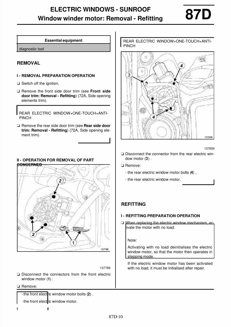
8/6/2019 8 - Electrical Equipment
http://slidepdf.com/reader/full/8-electrical-equipment 187/29487D-10
ELECTRIC WINDOWS - SUNROOF
Window winder motor: Removal - Refitting 87D
REMOVAL
I - REMOVAL PREPARATION OPERATION
a Switch off the ignition.
a Remove the front side door trim (see Front sidedoor trim: Removal - Refitting) (72A, Side openingelements trim).
a Remove the rear side door trim (see Rear side doortrim: Removal - Refitting) (72A, Side opening ele-ment trim).
II - OPERATION FOR REMOVAL OF PARTCONCERNED
a Disconnect the connectors from the front electricwindow motor (1) .
a Remove:
- the front electric window motor bolts (2) .
- the front electric window motor.
a Disconnect the connector from the rear electric win-dow motor (3) .
a Remove:
- the rear electric window motor bolts (4) ,
- the rear electric window motor.
REFITTING
I - REFITTING PREPARATION OPERATION
a When replacing the electric window mechanism, ac-
tivate the motor with no load.
Essential equipment
diagnostic tool
REAR ELECTRIC WINDOW+ONE-TOUCH+ANTI-PINCH
137789
REAR ELECTRIC WINDOW+ONE-TOUCH+ANTI-PINCH
137659
Note:
Activating with no load deinitialises the electricwindow motor, so that the motor then operates instepping mode.
If the electric window motor has been activatedwith no load, it must be initialised after repair.

8/6/2019 8 - Electrical Equipment
http://slidepdf.com/reader/full/8-electrical-equipment 188/29487D-11
ELECTRIC WINDOWS - SUNROOF
Window winder motor: Removal - Refitting 87DII - REFITTING OPERATION FOR PARTCONCERNED
a Refit the front electric window motor.
a Connect the front electric window motor connectors.
a Refit the rear electric window motor.
a Connect the rear electric window motor connector.
III - FINAL OPERATION
a Refit the front side door trim (see Front side doortrim: Removal - Refitting) (72A, Side opening ele-
ments trim).
a Refit the rear side door trim (see Rear side doortrim: Removal - Refitting) (72A, Side opening ele-ment trim).
a When replacing a front electric window motor, applythe after repair procedure using the diagnostic tool:
- connect the diagnostic tool,
- select « Driver's door electric window computer » ifthe motor is fitted on the driver's side front door,
-select «Passenger door electric windowcomputer » if the engine is fitted on the passengerside front door,
- go to repair mode,
- display the « before/after repair procedure » for thecomputer selected,
- carry out the operations described in the « After re-pair procedure » section.
Note:
It may be necessary to activate the motor with noload in order to couple the motor pulley and theelectric window mechanism crownwheel.
REAR ELECTRIC WINDOW+ONE-TOUCH+ANTI-PINCH
Note:
It may be necessary to activate the motor with noload in order to couple the motor pulley and theelectric window mechanism crownwheel.
REAR ELECTRIC WINDOW+ONE-TOUCH+ANTI-PINCH

8/6/2019 8 - Electrical Equipment
http://slidepdf.com/reader/full/8-electrical-equipment 189/29487D-12
ELECTRIC WINDOWS - SUNROOF
Sunroof switch: Removal - Refitting
PANORAMIC SUNROOF
87D
REMOVAL
OPERATION FOR REMOVAL OF PARTCONCERNED
a Unclip the sunroof switch trim at (1) using the tool(Car. 1363).
a Unclip the sunroof switch trim at (2) using the tool
(Car. 1363) .
a Disconnect the sunroof switch connector.
a Disconnect the connector from the "hands-free" mi-crophone.
Essential special tooling
Car. 1363 Set of trim removal levers.
136961
136962
RADIO NO 02 or RADIO NO 03 or RADIO NO 04or RADIO NO 05 or RADIO NO 06 or RADIO NO
07

8/6/2019 8 - Electrical Equipment
http://slidepdf.com/reader/full/8-electrical-equipment 190/294

8/6/2019 8 - Electrical Equipment
http://slidepdf.com/reader/full/8-electrical-equipment 191/294

8/6/2019 8 - Electrical Equipment
http://slidepdf.com/reader/full/8-electrical-equipment 192/29487D-15
ELECTRIC WINDOWS - SUNROOF
Sunroof opening motor Removal - Refitting
PANORAMIC SUNROOF
87D
In the event of a fault, the sunroof motor can be movedmanually using an Allen key at (1) .
REMOVAL
I - REMOVAL PREPARATION OPERATION
a Switch off the ignition.
a Disconnect the battery (see 80A, Battery, Battery :Removal - Refitting, page 80A-2) .
a Remove the headlining (see Headlining: Removal -Refitting) (71A, Body internal trim).
II - OPERATION FOR REMOVAL OF PARTCONCERNED
a Disconnect the connector (2) from the sunroof mo-tor.
a Remove:
- the bolts (3) from the sunroof motor,
- the sunroof motor.
REFITTING
I - REFITTING OPERATION FOR PARTCONCERNED
a Refit the sunroof motor.
a Connect the sunroof motor connector.
II - FINAL OPERATION
a Refit the headlining (see Headlining: Removal -Refitting) (71A, Body internal trim).
a Connect the battery (see 80A, Battery, Battery :Removal - Refitting, page 80A-2) .
a Switch on the ignition.
a Apply the after repair procedure using the diagnos-tic tool :
- connect the diagnostic tool,
- select "Roof opening element computer",
- go to repair mode,
- display the "Before/After repair procedure",
Essential equipment
diagnostic tool
137657
Note:
The sunroof computer is integrated into the sunroofmotor.
137657

8/6/2019 8 - Electrical Equipment
http://slidepdf.com/reader/full/8-electrical-equipment 193/29487D-16
ELECTRIC WINDOWS - SUNROOF
Sunroof opening motor Removal - Refitting
PANORAMIC SUNROOF
87D
- select "Roof opening element computer" in the "Listof components controlled by this computer" sec-tion,
- carry out the operations described in the "After re-
pair procedure" section.

8/6/2019 8 - Electrical Equipment
http://slidepdf.com/reader/full/8-electrical-equipment 194/29487F-1
PARKING DISTANCE CONTROL
Parking proximity sensor: List and location of components
FR AND RR PROX RADAR or REAR PROX RADAR
87F
I - LIST OF COMPONENTS
The parking distance control equipment consistsof:
- a parking distance control switch
- a parking distance control computer
- rear proximity sensors
- a rear parking distance control buzzer
- front proximity sensors
- a front parking distance control buzzer
II - LOCATION OF COMPONENTS
Parking distance control switch
Parking distance control computer
Rear proximity sensors
FR AND RR PROX RADAR
137110
137103
135331

8/6/2019 8 - Electrical Equipment
http://slidepdf.com/reader/full/8-electrical-equipment 195/294

8/6/2019 8 - Electrical Equipment
http://slidepdf.com/reader/full/8-electrical-equipment 196/29487F-3
PARKING DISTANCE CONTROL
Parking proximity sensor: List and location of components
FR AND RR PROX RADAR or REAR PROX RADAR
87F
Front parking distance control buzzer
136959

8/6/2019 8 - Electrical Equipment
http://slidepdf.com/reader/full/8-electrical-equipment 197/29487F-4
PARKING DISTANCE CONTROL
Parking proximity sensor switch: Removal - Refitting
FR AND RR PROX RADAR or REAR PROX RADAR
87F
REMOVAL
I - REMOVAL PREPARATION OPERATION
a Switch off the ignition.
a Open the access flap on the passenger compart-ment fuse box (1) .
a Unclip the switch plate at (2) using the (Car. 1363).
a Disconnect the switch plate connectors.
II - OPERATION FOR REMOVAL OF PARTCONCERNED
a Unclip the parking distance control switch by pres-sing on the clips (3) .
Essential special tooling
Car. 1363 Set of trim removal levers.
137114
137116
137112

8/6/2019 8 - Electrical Equipment
http://slidepdf.com/reader/full/8-electrical-equipment 198/294

8/6/2019 8 - Electrical Equipment
http://slidepdf.com/reader/full/8-electrical-equipment 199/294

8/6/2019 8 - Electrical Equipment
http://slidepdf.com/reader/full/8-electrical-equipment 200/29487F-7
PARKING DISTANCE CONTROL
Parking proximity sensor buzzer: Removal - Refitting
FR AND RR PROX RADAR or REAR PROX RADAR
87F
- the rear left-hand parcel shelf side trim (see Rearparcel shelf trim: Removal - Refitting) (71A,Body internal trim).
a Refit the dashboard lower trim (see Lower sectionof dashboard trim: Removal - Refitting) (57A, In-terior equipment).
FR AND RR PROX RADAR

8/6/2019 8 - Electrical Equipment
http://slidepdf.com/reader/full/8-electrical-equipment 201/29487F-8
PARKING DISTANCE CONTROL
Proximity radar Removal - Refitting
FR AND RR PROX RADAR or REAR PROX RADAR
87F
REMOVAL
I - REMOVAL PREPARATION OPERATION
a Switch off the ignition.
a Position the vehicle on a two-post lift (see Vehicle:
Towing and lifting) (02A, Lifting equipment).
a Remove:
- the rear wheels (see Wheel: Removal - Refitting)(35A, Wheels and tyres),
- the rear wheel arch liners (see Rear wheel archliner: Removal - Refitting) (55A, Exterior protec-tion),
- the rear lights on the wing (see 81A, Rear lighting,
Rear light on wing: Removal - Refitting, page81A-5) ,
- the rear bumper (see Rear bumper: Removal -Refitting) (55A, Exterior protection).
a Remove:
- the front section of the front wheel arch liners (see
Front wheel arch liner: Removal - Refitting)(55A, Exterior protection),
- the front bumper (see Front bumper: Removal -Refitting) (55A, Exterior protection).
II - OPERATION FOR REMOVAL OF PARTCONCERNED
a Disconnect the connectors (1) from the proximitysensors.
a Unclip the proximity sensors by pressing the clips (2).
WARNING
The proximity sensors are fragile. Handle with care
as the external part cannot withstand impacts.
FR AND RR PROX RADAR
137098
137101

8/6/2019 8 - Electrical Equipment
http://slidepdf.com/reader/full/8-electrical-equipment 202/294

8/6/2019 8 - Electrical Equipment
http://slidepdf.com/reader/full/8-electrical-equipment 203/29487F-10
PARKING DISTANCE CONTROL
Proximity radar Removal - Refitting
FR AND RR PROX RADAR or REAR PROX RADAR
87F
1 - Centre proximity sensors
a Clip the proximity sensors onto their mountings.
a Clip the proximity sensor mountings onto the front
bumper.
a Connect the proximity sensor connectors.
2 - Side proximity sensors
a Clip the proximity sensors into place.
a Connect the proximity sensor connectors.
II - FINAL OPERATION
a Refit:
- the rear bumper (see Rear bumper: Removal -Refitting) (55A, Exterior protection),
- the rear lights on the wing (see 81A, Rear lighting,
Rear light on wing: Removal - Refitting, page
81A-5) ,
- the rear wheel arch liners (see Rear wheel arch
liner: Removal - Refitting) (55A, Exterior protec-
tion),
- the rear wheels (see Wheel: Removal - Refitting)
(35A, Wheels and tyres).
a Refit:
- the front bumper (see Front bumper: Removal -
Refitting) (55A, Exterior protection),
- the front section of the front wheel arch liners (see
Front wheel arch liner: Removal - Refitting)
(55A, Exterior protection).
FR AND RR PROX RADAR
FR AND RR PROX RADAR

8/6/2019 8 - Electrical Equipment
http://slidepdf.com/reader/full/8-electrical-equipment 204/294

8/6/2019 8 - Electrical Equipment
http://slidepdf.com/reader/full/8-electrical-equipment 205/294

8/6/2019 8 - Electrical Equipment
http://slidepdf.com/reader/full/8-electrical-equipment 206/29487G-1
ENGINE COMPARTMENT CONNECTION UNIT
Protection and Switching Unit: Removal - Refitting 87G
REMOVAL
I - REMOVAL PREPARATION OPERATION
a In the event of replacement, apply the before repairprocedure using the diagnostic tool :
- connect the diagnostic tool,
- select "Protection and Switching Unit",
- go to repair mode,
- display the "Before/after repair procedure" for thecomputer selected,
- carry out the operations described in the "Beforerepair procedure" section.
a Switch off the ignition.
a Disconnect the battery (see 80A, Battery, Battery :Removal - Refitting, page 80A-2) .
II - OPERATION FOR REMOVAL OF PARTCONCERNED
a Unlock the safety devices of the Protection and Swit-ching Unit cover.
a Unclip the Protection and Switching Unit cover.
Essential equipment
diagnostic tool
137067
Note:
When the cover is locked, a coloured mark (1) isvisible at the rear lock.
When the cover is unlocked, a coloured mark isvisible at the front lock.

8/6/2019 8 - Electrical Equipment
http://slidepdf.com/reader/full/8-electrical-equipment 207/294

8/6/2019 8 - Electrical Equipment
http://slidepdf.com/reader/full/8-electrical-equipment 208/29487G-3
ENGINE COMPARTMENT CONNECTION UNIT
Protection and Switching Unit: Removal - Refitting 87GREFITTING
I - REFITTING OPERATION FOR PARTCONCERNED
a Connect the Protection and Switching Unit connec-tors according to their position marked during remo-val.
a Clip the Protection and Switching Unit onto its unit.
a Refit:
- the rubber rings of the Protection and SwitchingUnit wiring onto the unit,
- the bracket of the passenger compartment wiringof the Protection and Switching Unit.
a Clip the Protection and Switching Unit cover onto theunit.
a Lock the safety devices of the Protection and Swit-
ching Unit cover.
II - FINAL OPERATION
a Connect the battery (see 80A, Battery, Battery :Removal - Refitting, page 80A-2) .
a In the event of a replacement, apply the after repairprocedure using the diagnostic tool :
- connect the diagnostic tool,
- select "Protection and Switching Unit",
- go to repair mode,
- display the "Before/after repair procedure" for thecomputer selected,
- carry out the operations described in the "After re-pair procedure" section.
Note:
Connect the connectors with the shortest wiringfirst to avoid stressing the wiring and dislodging aconnector.
Note:
If the Protection and Switching Unit does not clipon correctly, check the condition of the wiring ofthe Protection and Switching Unit connectors.
137067
Note:
A coloured mark (6) is visible at the rear lockwhen the cover is correctly locked.

8/6/2019 8 - Electrical Equipment
http://slidepdf.com/reader/full/8-electrical-equipment 209/29488A-1
WIRING HARNESS
Computers List and location of components 88A
The vehicle is fitted with:
- an injection computer (1)
- a UPC (2)
- a UCH (3)
- a passenger compartment fuse and relay box (4)
- an airbag computer (5)
- a hydraulic brake unit (6)
- an instrument panel (7)
- an automatic transmission computer (8)
- a front lighting computer (9)
- an electronic parking brake control unit (10)
- a parking distance control computer (11)
- an air conditioning control panel (12)
- a radionavigation system (13)
- a navigation screen (14)
136983
6 SPEED AUTO GBOX
XENON BULBS
ELEC PARKING BRAKE
FR AND RR PROX RADAR or REAR PROXRADAR
AIR CONDITIONING or CLIMATE CONTROL
RADIO NO 06 or RADIO NO 07

8/6/2019 8 - Electrical Equipment
http://slidepdf.com/reader/full/8-electrical-equipment 210/29488A-2
WIRING HARNESS
Computers List and location of components 88A- a multimedia network interface unit (15)
- a navigation computer (16)
- a receiver (17)
- a radio (18)
- a display (19)
- an offset multimedia socket computer (20)
RADIO NO 07
RADIO NO 01 or RADIO NO 02 or RADIO NO 03or RADIO NO 04 or RADIO NO 05
RADIO NO 01 or RADIO NO 02 or RADIO NO 03or RADIO NO 04 or RADIO NO 05 or VEHICLEWITHOUT RADIO
RADIO NO 04 or RADIO NO 05

8/6/2019 8 - Electrical Equipment
http://slidepdf.com/reader/full/8-electrical-equipment 211/294

8/6/2019 8 - Electrical Equipment
http://slidepdf.com/reader/full/8-electrical-equipment 212/294

8/6/2019 8 - Electrical Equipment
http://slidepdf.com/reader/full/8-electrical-equipment 213/29488A-5
WIRING HARNESS
Front bumper wiring: Connector opening
FOG LIGHT – FR AND RR PROX RADAR
88A
I - LOCATION OF CONNECTORS
a R 106 connector (1) (passenger compartment/frontbumper connection).
II - ACCESS TO CONNECTORS
a
a Switch off the ignition.
a Disconnect the battery (see 80A, Battery, Battery :Removal - Refitting, page 80A-2) .
a Position the vehicle on a two-post lift (see Vehicle:Towing and lifting) (02A, Lifting equipment).
a the front section of the front right-hand wheel archliner (see Front wheel arch liner: Removal - Refit-ting) (55A, Exterior protection).
136971
IMPORTANT
To avoid all risk of damage to the systems, applythe safety and cleanliness instructions and ope-ration recommendations before carrying out anyrepair (see 88A , Wiring harness, Wiring: Pre-cautions for repair, page 88A-4) .
WARNING
To avoid damaging the connectors, consult thedisconnection procedures (see Connector: Dis-connection and reconnection) (Technical Note6105A, 88A, Wiring).

8/6/2019 8 - Electrical Equipment
http://slidepdf.com/reader/full/8-electrical-equipment 214/29488A-6
WIRING HARNESS
Front bumper wiring: Connector opening
FOG LIGHT – FR AND RR PROX RADAR
88A
a Unclip the connector (2) from the front end panel.
a Disconnect the R 106 connector.
137367

8/6/2019 8 - Electrical Equipment
http://slidepdf.com/reader/full/8-electrical-equipment 215/29488A-7
WIRING HARNESS
Front bumper wiring: Removal - Refitting
FOG LIGHT – FR AND RR PROX RADAR
88A
REMOVAL
I - REMOVAL PREPARATION OPERATION
a Position the vehicle on a two-post lift (see Vehicle:Towing and lifting) (02A, Lifting equipment).
a Switch off the ignition.
a Disconnect the battery (see 80A, Battery, Battery :Removal - Refitting, page 80A-2) .
aRemove:- the front wheels (see Wheel: Removal - Refitting)(35A, Wheels and tyres),
- the front wheel arch liners (see Front wheel archliner: Removal - Refitting) (55A, Exterior protec-tion),
- the front bumper (see Front bumper: Removal -Refitting) (55A, Exterior protection).
II - OPERATION FOR REMOVAL OF PARTCONCERNED
a
IMPORTANT
To avoid all risk of damage to the systems, apply
the safety and cleanliness instructions and opera-tion recommendations before carrying out anyrepair (see 88A, Wiring harness, Wiring: Precau-tions for repair, page 88A-4) .
WARNING
To avoid damaging the connectors, consult the dis-connection procedures (see Connector: Discon-
nection and reconnection) (Technical Note6015A, 88A, Wiring).
WARNING
To prevent any risk of noise, premature wear,short circuits, etc. after the refitting operation,mark the wiring routing and how to connect theconnectors.

8/6/2019 8 - Electrical Equipment
http://slidepdf.com/reader/full/8-electrical-equipment 216/29488A-8
WIRING HARNESS
Front bumper wiring: Removal - Refitting
FOG LIGHT – FR AND RR PROX RADAR
88A
a Disconnect the front fog light connectors (1) .
FOG LIGHT
137087
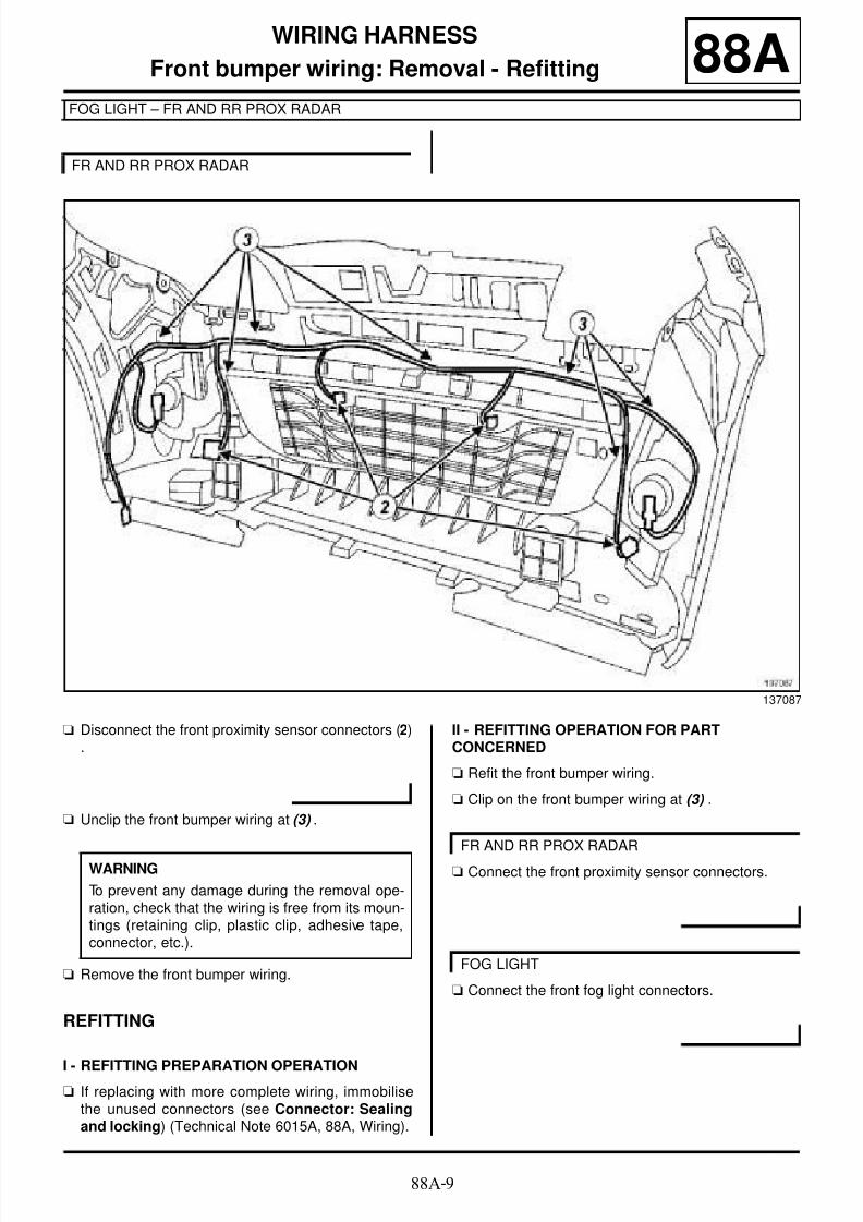
8/6/2019 8 - Electrical Equipment
http://slidepdf.com/reader/full/8-electrical-equipment 217/29488A-9
WIRING HARNESS
Front bumper wiring: Removal - Refitting
FOG LIGHT – FR AND RR PROX RADAR
88A
a Disconnect the front proximity sensor connectors (2).
a Unclip the front bumper wiring at (3) .
a Remove the front bumper wiring.
REFITTING
I - REFITTING PREPARATION OPERATIONa If replacing with more complete wiring, immobilise
the unused connectors (see Connector: Sealingand locking) (Technical Note 6015A, 88A, Wiring).
II - REFITTING OPERATION FOR PARTCONCERNED
a Refit the front bumper wiring.
a Clip on the front bumper wiring at (3) .
a Connect the front proximity sensor connectors.
a Connect the front fog light connectors.
FR AND RR PROX RADAR
137087
WARNING
To prevent any damage during the removal ope-ration, check that the wiring is free from its moun-tings (retaining clip, plastic clip, adhesive tape,connector, etc.).
FR AND RR PROX RADAR
FOG LIGHT

8/6/2019 8 - Electrical Equipment
http://slidepdf.com/reader/full/8-electrical-equipment 218/294

8/6/2019 8 - Electrical Equipment
http://slidepdf.com/reader/full/8-electrical-equipment 219/29488A-11
WIRING HARNESS
Driver's front side door wiring: Removal - Refitting 88A
REMOVAL
I - REMOVAL PREPARATION OPERATION
a Raise the window fully.
aApply the Before repair procedure using the dia-gnostic tool :
- connect the diagnostic tool,
- select « Airbag computer » ,
- go to repair mode,
- display the « before/after repair procedure » for thecomputer selected,
- carry out the operations described in the « Beforerepair procedure » section.
a Switch off the ignition.
a Disconnect the battery (see 80A, Battery, Battery :Removal - Refitting, page 80A-2) .
a Remove:
- the front side door trim (see Front side door trim:Removal - Refitting) (72A, Side opening elementtrim),
- the front side door sealing film (see Door sealingfilm: Removal - Refitting) (65A, Opening elementsealing),
- the side impact sensor on the front side door (see88C, Air bag and Pretensioners, Side impactsensor: Removal - Refitting, page 88C-26) ,
- the front electric window motor (see 87D, Electricwindows - Sunroof, Window winder motor: Re-moval - Refitting, page 87D-10) ,
- the front side door electric window mechanism (seeFront side door electric window mechanism:
Removal - Refitting) (51A, Side opening elementmechanisms),
- the front side door lock (see Front side door lock:Removal - Refitting) (51A, Side opening elementmechanisms).
Essential equipment
diagnostic tool
IMPORTANT
To avoid all risk of damage to the systems, applythe safety and cleanliness instructions and opera-tion recommendations before carrying out anyrepair (see 88A, Wiring harness, Wiring: Precau-tions for repair, page 88A-4) .
WARNING
To avoid damaging the connectors, consult the dis-connection procedures (see Connector: Discon-nection and reconnection) (Technical Note6015A, 88A, Wiring).
IMPORTANT
To avoid any r isk of triggering when working onor near a pyrotechnic component (airbags or pre-tensioners), lock the airbag computer using thediagnostic tool.
When this function is activated, all the triggerlines are inhibited and the airbag warning light onthe instrument panel lights up continuously (igni-tion on).

8/6/2019 8 - Electrical Equipment
http://slidepdf.com/reader/full/8-electrical-equipment 220/29488A-12
WIRING HARNESS
Driver's front side door wiring: Removal - Refitting 88AII - OPERATION FOR REMOVAL OF PART
CONCERNED
a
aUnlock at (6) the front side door connector (1) .
a Disconnect:
- the front side door connector (1) ,
- the speaker connector (2) on the front side door,
- the door mirror connector (3) .
a Disconnect the connectors (4) from the front side
door handle.
a Unclip the clips (5) from the front side door wiring.
a Remove the front side door wiring.
REFITTING
I - REFITTING PREPARATION OPERATION
a If replacing with more complete wiring, immobilisethe unused connectors (see Connector: Sealingand locking) (Technical Note 6015A, 88A, Wiring).
136976
WARNING
To prevent any risk of noise, premature wear,short circuits, etc. after the refitting operation,mark the wiring routing and how to connect theconnectors.
DOOR OPEN SYST. 433 NML
WARNING
To prevent any damage during the removal ope-ration, check that the wiring is free from its moun-tings (retaining clip, plastic clip, adhesive tape,
connector, etc.).

8/6/2019 8 - Electrical Equipment
http://slidepdf.com/reader/full/8-electrical-equipment 221/29488A-13
WIRING HARNESS
Driver's front side door wiring: Removal - Refitting 88AII - REFITTING OPERATION FOR PARTCONCERNED
a
a Refit the front side door wiring.
a Clip on the front side door wiring clips at (5) .
a Connect:
- the door mirror connector,
- the front side door speaker connector,
- the front side door connector.
a Lock the side door connector (1) by fully pushingdown on the lock.
a Connect the connectors on the front side door han-dle.
III - FINAL OPERATION
a Refit:
- the front side door lock (see Front side door lock:Removal - Refitting) (51A, Side opening element
mechanisms),
- the front side door electric window mechanism (seeFront side door electric window mechanism:Removal - Refitting) (51A, Side opening elementmechanisms),
- the front electric window motor (see 87D, Electricwindows - Sunroof, Window winder motor: Re-moval - Refitting, page 87D-10) ,
- the side impact sensor on the front side door (see88C, Air bag and Pretensioners, Side impact
sensor: Removal - Refitting, page
88C-26) ,
- the front side door sealing film (see Door sealingfilm: Removal - Refitting) (65A, Opening elementsealing),
- the front side door trim (see Front side door trim:Removal - Refitting) (72A, Side opening elementtrim).
a Connect the battery (see 80A, Battery, Battery :Removal - Refitting, page 80A-2) .
a Apply the After repair procedure using the diagnos-tic tool :
- connect the diagnostic tool,
- select « Airbag computer » ,
- go to repair mode,
- display the « before/after repair procedure » for thecomputer selected,
- carry out the operations described in the « After re-pair procedure » section.
IV - CHECKING AFTER REPAIR
a Switch on the ignition.
a Check the operation of all front side door compo-nents.
a Check the operation of all the components control-led by the front side door controls.
WARNING
To prevent damage to the wiring harness whenrefitting, observe the original routing.
Note:
Check that the lock (6) is fully engaged (possiblepoor connection otherwise).
DOOR OPEN SYST. 433 NML

8/6/2019 8 - Electrical Equipment
http://slidepdf.com/reader/full/8-electrical-equipment 222/29488A-14
WIRING HARNESS
Passenger's front side door wiring: Removal - Refitting 88A
REMOVAL
I - REMOVAL PREPARATION OPERATION
a Raise the window fully.
aApply the Before repair procedure using the dia-gnostic tool :
- connect the diagnostic tool,
- select « Airbag computer » ,
- go to repair mode,
- display the « before/after repair procedure » for thecomputer selected,
- carry out the operations described in the « Beforerepair procedure » section.
a Switch off the ignition.
a Disconnect the battery (see 80A, Battery, Battery :Removal - Refitting, page 80A-2) .
a Remove:
- the front side door trim (see Front side door trim:Removal - Refitting) (72A, Side opening elementtrim),
- the front side door sealing film (see Door sealingfilm: Removal - Refitting) (65A, Opening elementsealing),
- the side impact sensor on the front side door (see88C, Air bag and Pretensioners, Side impactsensor: Removal - Refitting, page 88C-26) ,
- the front electric window motor (see 87D, Electricwindows - Sunroof, Window winder motor: Re-moval - Refitting, page 87D-10) ,
- the front side door electric window mechanism (seeFront side door electric window mechanism:
Removal - Refitting) (51A, Side opening elementmechanism),
- the front side door lock (see Front side door lock:Removal - Refitting) (51A, Side opening elementmechanism).
Essential equipment
diagnostic tool
IMPORTANT
To avoid all risk of damage to the systems, applythe safety and cleanliness instructions and opera-tion recommendations before carrying out anyrepair (see 88A, Wiring harness, Wiring: Precau-tions for repair, page 88A-4) .
WARNING
To avoid damaging the connectors, consult the dis-connection procedure (see Connector: Discon-nection and reconnection) (Technical Note6015A, 88A, Wiring).
IMPORTANT
To avoid any r isk of triggering when working onor near a pyrotechnic component (airbags or pre-tensioners), lock the airbag computer using thediagnostic tool.
When this function is activated, all the triggerlines are inhibited and the airbag warning light onthe instrument panel lights up continuously (igni-tion on).

8/6/2019 8 - Electrical Equipment
http://slidepdf.com/reader/full/8-electrical-equipment 223/29488A-15
WIRING HARNESS
Passenger's front side door wiring: Removal - Refitting 88AII - REFITTING OPERATION FOR PART
CONCERNED
a
aUnlock at (6) the front side door connector (1) .
a Disconnect:
- the front side door connector (1) ,
- the speaker connector (2) on the front side door,
- the door mirror connector (3) .
a Disconnect the connectors (4) from the front side
door handle.
a Unclip the clips (5) from the front side door wiring.
a Remove the front side door wiring.
REFITTING
I - REFITTING PREPARATION OPERATION
a If replacing with more complete wiring, immobilisethe unused connectors (see Connector: Sealingand locking) (Technical Note 6015A, 88A, Wiring).
136978
WARNING
To prevent any risk of noise, premature wear,short circuits, etc. after the refitting operation,mark the wiring routing and how to connect theconnectors.
DOOR OPEN SYST. 433 NML
WARNING
To prevent any damage during the removal ope-ration, check that the wiring is free from its moun-tings (retaining clip, plastic clip, adhesive tape,
connector, etc.).

8/6/2019 8 - Electrical Equipment
http://slidepdf.com/reader/full/8-electrical-equipment 224/29488A-16
WIRING HARNESS
Passenger's front side door wiring: Removal - Refitting 88AII - REFITTING OPERATION FOR PARTCONCERNED
a
a Refit the front side door wiring.
a Clip on the front side door wiring clips at (5) .
a Connect:
- the door mirror connector,
- the front side door speaker connector,
- the side door connector.
a Lock the side door connector (1) by fully pushingdown on the lock.
a Connect the connectors on the front side door han-dle.
III - FINAL OPERATION
a Refit:
- the front side door lock (see Front side door lock:Removal - Refitting) (51A, Side opening element
mechanism),
- the front side door electric window mechanism (seeFront side door electric window mechanism:Removal - Refitting) (51A, Side opening elementmechanism),
- the front electric window motor (see 87D, Electricwindows - Sunroof, Window winder motor: Re-moval - Refitting, page 87D-10) ,
- the side impact sensor on the front side door (see88C, Air bag and Pretensioners, Side impact
sensor: Removal - Refitting, page
88C-26) ,
- the front side door sealing film (see Door sealingfilm: Removal - Refitting) (65A, Opening elementsealing),
- the front side door trim (see Front side door trim:Removal - Refitting) (72A, Side opening elementtrim).
a Connect the battery (see 80A, Battery, Battery :Removal - Refitting, page 80A-2) .
a Apply the after repair procedure using the diagnos-tic tool :
- connect the diagnostic tool,
- select « Airbag computer » ,
- go to repair mode,
- display the « before/after repair procedure » for thecomputer selected,
- carry out the operations described in the « After re-pair procedure » section.
IV - CHECKING AFTER REPAIR
a Switch on the ignition.
a Check the operation of all front side door compo-nents.
WARNING
To prevent damage to the wiring harness whenrefitting, observe the original routing.
Note:
Check that the lock (6) is fully engaged (possiblepoor connection otherwise).
DOOR OPEN SYST. 433 NML

8/6/2019 8 - Electrical Equipment
http://slidepdf.com/reader/full/8-electrical-equipment 225/29488A-17
WIRING HARNESS
Rear right-hand side door wiring: Removal - Refitting 88A
REMOVAL
I - REMOVAL PREPARATION OPERATION
a Raise the window fully.
a Switch off the ignition.
a Disconnect the battery (see 80A, Battery, Battery :Removal - Refitting, page 80A-2) .
a Remove:
- the rear side door trim (seeRear side door trim:Removal - Refitting) (72A, Side opening element
trim),
- the door sealing film (see Door sealing film: Re-moval - Refitting) (65A, Opening element sea-ling).
a Remove:
- the rear side door lock bolts (1) ,
- the rear side door lock (partially).
IMPORTANT
To avoid all risk of damage to the systems, applythe safety and cleanliness instructions and opera-
tion recommendations before carrying out anyrepair (see 88A, Wiring harness, Wiring: Precau-tions for repair, page 88A-4) .
WARNING
To avoid damaging the connectors, consult the dis-connection procedures (see Connector: Discon-nection and reconnection) (Technical Note6015A, 88A, Wiring).
136158

8/6/2019 8 - Electrical Equipment
http://slidepdf.com/reader/full/8-electrical-equipment 226/29488A-18
WIRING HARNESS
Rear right-hand side door wiring: Removal - Refitting 88AII - OPERATION FOR REMOVAL OF PARTCONCERNED
a
a Disconnect:
- the rear side door connector (2) ,
- the rear speaker connector (3) ,
- the rear side door lock connector (4) .
a Disconnect the rear electric window motor connector
(5) .
a Disconnect the rear side door handle connector (6) .
a Unclip the clips (7) from the rear side door wiring.
a Remove the rear side door wiring.
REFITTING
I - REFITTING PREPARATION OPERATIONa If replacing with more complete wiring, immobilise
the unused connectors (see Connector: Sealingand locking) (Technical Note 6015A, 88A, Wiring).
136981
WARNING
To prevent any risk of noise, premature wear,short circuits, etc. after the refitting operation,mark the wiring routing and how to connect theconnectors.
REAR ELECTRIC WINDOW+ONE-TOUCH+ANTI-PINCH
DOOR OPEN SYST. 433 NML
WARNING
To prevent any damage during the removal ope-ration, check that the wiring is free from its moun-tings (retaining clip, plastic clip, adhesive tape,connector, etc.).

8/6/2019 8 - Electrical Equipment
http://slidepdf.com/reader/full/8-electrical-equipment 227/294

8/6/2019 8 - Electrical Equipment
http://slidepdf.com/reader/full/8-electrical-equipment 228/29488A-20
WIRING HARNESS
Rear left-hand side door wiring: Removal - Refitting 88A
REMOVAL
I - REMOVAL PREPARATION OPERATION
a Raise the window fully.
a Switch off the ignition.
a Disconnect the battery (see 80A, Battery, Battery :Removal - Refitting, page 80A-2) .
a Remove:
- the rear side door trim (seeRear side door trim:Removal - Refitting) (72A, Side opening element
trim),
- the door sealing film (see Door sealing film: Re-moval - Refitting) (65A, Opening element sea-ling).
a Remove:
- the rear side door lock bolts (1) ,
- the rear side door lock (partially).
IMPORTANT
To avoid all risk of damage to the systems, applythe safety and cleanliness instructions and opera-
tion recommendations before carrying out anyrepair (see 88A, Wiring harness, Wiring: Precau-tions for repair, page 88A-4) .
WARNING
To avoid damaging the connectors, consult the dis-connection procedure (see Connector: Discon-nection and reconnection) (Technical Note6015A, 88A, Wiring).
136158
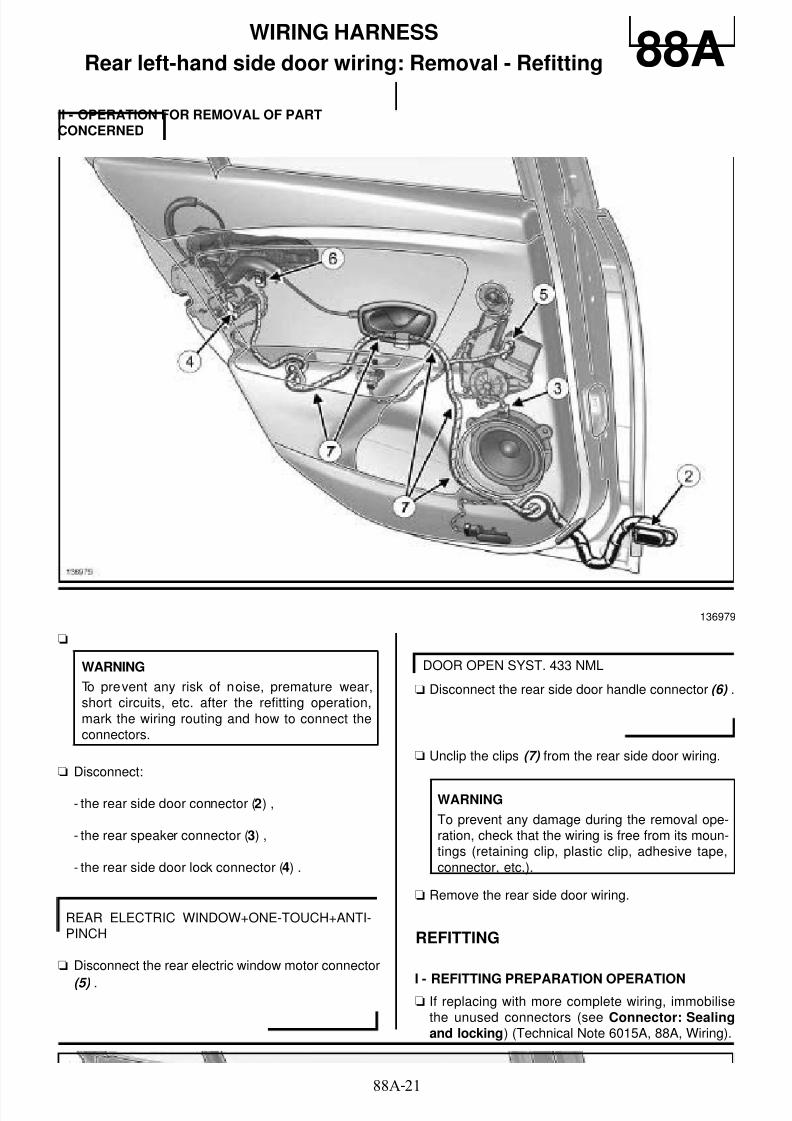
8/6/2019 8 - Electrical Equipment
http://slidepdf.com/reader/full/8-electrical-equipment 229/29488A-21
WIRING HARNESS
Rear left-hand side door wiring: Removal - Refitting 88AII - OPERATION FOR REMOVAL OF PARTCONCERNED
a
a Disconnect:
- the rear side door connector (2) ,
- the rear speaker connector (3) ,
- the rear side door lock connector (4) .
a Disconnect the rear electric window motor connector
(5) .
a Disconnect the rear side door handle connector (6) .
a Unclip the clips (7) from the rear side door wiring.
a Remove the rear side door wiring.
REFITTING
I - REFITTING PREPARATION OPERATIONa If replacing with more complete wiring, immobilise
the unused connectors (see Connector: Sealingand locking) (Technical Note 6015A, 88A, Wiring).
136979
WARNING
To prevent any risk of noise, premature wear,short circuits, etc. after the refitting operation,mark the wiring routing and how to connect theconnectors.
REAR ELECTRIC WINDOW+ONE-TOUCH+ANTI-PINCH
DOOR OPEN SYST. 433 NML
WARNING
To prevent any damage during the removal ope-ration, check that the wiring is free from its moun-tings (retaining clip, plastic clip, adhesive tape,connector, etc.).

8/6/2019 8 - Electrical Equipment
http://slidepdf.com/reader/full/8-electrical-equipment 230/29488A-22
WIRING HARNESS
Rear left-hand side door wiring: Removal - Refitting 88AII - REFITTING OPERATION FOR PARTCONCERNED
a
a Refit the rear side door wiring.
a Clip on the rear side door wiring clips at (7) .
a Connect:
- the rear side door lock connector,
- the rear speaker connector,
- the rear side door connector.
a Connect the rear electric window motor connector.
a Connect the rear side door handle connector.
III - FINAL OPERATION
a Refit:
- the rear side door lock,
- the door sealing film (see Door sealing film: Re-moval - Refitting) (65A, Opening element sea-ling),
- the rear side door trim (see Rear side door trim:
Removal - Refitting) (72A, Side opening elementtrim).
a Connect the battery (see 80A, Battery, Battery :Removal - Refitting, page 80A-2) .
WARNING
To prevent damage to the wiring harness whenrefitting, observe the original routing.
REAR ELECTRIC WINDOW+ONE-TOUCH+ANTI-PINCH
DOOR OPEN SYST. 433 NML

8/6/2019 8 - Electrical Equipment
http://slidepdf.com/reader/full/8-electrical-equipment 231/29488A-23
WIRING HARNESS
Rear bumper wiring: Connector opening 88AI - LOCATION OF CONNECTORS
a R 319 connector (1) (rear bumper/rear connection).
B95
136973

8/6/2019 8 - Electrical Equipment
http://slidepdf.com/reader/full/8-electrical-equipment 232/29488A-24
WIRING HARNESS
Rear bumper wiring: Connector opening 88A
a R 319 connector (2) (rear bumper/rear connection).
II - ACCESS TO CONNECTORS
a
a Position the vehicle on a two-post lift (see Vehicle:Towing and lifting) (02A, Lifting equipment).
a Remove:
- the rear lights on the wing (see 81A, Rear lighting,Rear light on wing: Removal - Refitting, page81A-5) ,
- the rear wheels (see Wheel: Removal - Refitting)(35A, Wheels and tyres),
- the rear wheel arch liners (see Rear wheel arch
liner: Removal - Refitting) (55A, Exterior protec-tion),
- the rear bumper (see Rear bumper: Removal -Refitting) (55A, Exterior protection).
a Disconnect the R 319 connector.
D95
136974
IMPORTANT
To avoid all risk of damage to the systems, applythe safety and cleanliness instructions and ope-ration recommendations before carrying out anyrepair (see 88A , Wiring harness, Wiring: Pre-cautions for repair, page 88A-4) .
WARNING
To avoid damaging the connectors, consult thedisconnection procedures (see Connector: Dis-connection and reconnection) (Technical Note6015A, 88A, Wiring).

8/6/2019 8 - Electrical Equipment
http://slidepdf.com/reader/full/8-electrical-equipment 233/29488A-25
WIRING HARNESS
Rear bumper wiring: Removal - Refitting 88A
REMOVAL
I - REMOVAL PREPARATION OPERATION
a Position the vehicle on a two-post lift (see Vehicle:Towing and lifting) (02A, Lifting equipment).
a Switch off the ignition.
a Disconnect the battery (see 80A, Battery, Battery :Removal - Refitting, page 80A-2) .
a Remove:
- the rear lights on the wing (see 81A, Rear lighting,
Rear light on wing: Removal - Refitting, page81A-5) ,
- the rear wheels (see Wheel: Removal - Refitting)(35A, Wheels and tyres),
- the rear wheel arch liners (see Rear wheel archliner: Removal - Refitting) (55A, Exterior protec-tion),
- the rear bumper (see Rear bumper: Removal -Refitting) (55A, Exterior protection).
II - OPERATION FOR REMOVAL OF PARTCONCERNED
a
a Disconnect the connectors (1) from the number pla- te lights.
IMPORTANT
To avoid all risk of damage to the systems, applythe safety and cleanliness instructions and opera-
tion recommendations before carrying out anyrepair (see 88A, Wiring harness, Wiring: Precau-tions for repair, page 88A-4) .
WARNING
To prevent any damage to the connectors, consultthe disconnection procedures (see Wiring: Discon-
nection and reconnection) (Technical Note6015A, 88A, Wiring).
WARNING
To prevent any risk of noise, premature wear,short circuits, etc. after the refitting operation,mark the wiring routing and how to connect theconnectors.
136973

8/6/2019 8 - Electrical Equipment
http://slidepdf.com/reader/full/8-electrical-equipment 234/29488A-26
WIRING HARNESS
Rear bumper wiring: Removal - Refitting 88A
a Disconnect the fog light connectors (2) .
D95
135336

8/6/2019 8 - Electrical Equipment
http://slidepdf.com/reader/full/8-electrical-equipment 235/29488A-27
WIRING HARNESS
Rear bumper wiring: Removal - Refitting 88A
a Disconnect the proximity sensor connectors (3) .
REAR PROX RADAR
137093

8/6/2019 8 - Electrical Equipment
http://slidepdf.com/reader/full/8-electrical-equipment 236/29488A-28
WIRING HARNESS
Rear bumper wiring: Removal - Refitting 88A
a Unclip the rear bumper wiring at (4) .
a Remove the rear bumper wiring.
REFITTING
I - REFITTING PREPARATION OPERATION
a If replacing with more complete wiring, immobilisethe unused connectors (see Wiring: Sealing and
locking) (Technical Note 6015A, 88A, Wiring).
II - REFITTING OPERATION FOR PARTCONCERNED
a Refit the rear bumper wiring.
a Clip the wiring onto the rear bumper at (4) .
a Connect the proximity sensor connectors.
a Connect the fog light connectors.
a Connect the number plate light connectors.
III - FINAL OPERATION
a Refit:
- the rear bumper (see Rear bumper: Removal -Refitting) (55A, Exterior protection),
- the rear wheel arch liners (see Rear wheel arch
liner: Removal - Refitting) (55A, Exterior protec-tion),
- the rear wheels (see Wheel: Removal - Refitting)(35A, Wheels and tyres),
137093
WARNING
To prevent any damage during the removal ope-ration, check that the wiring is free from its moun-tings (retaining clip, plastic clip, adhesive tape,connector, etc.).
REAR PROX RADAR
D95

8/6/2019 8 - Electrical Equipment
http://slidepdf.com/reader/full/8-electrical-equipment 237/29488A-29
WIRING HARNESS
Rear bumper wiring: Removal - Refitting 88A- the rear lights on the wing (see 81A, Rear lighting,Rear light on wing: Removal - Refitting, page81A-5) .
a Connect the battery (see 80A, Battery, Battery :Removal - Refitting, page 80A-2) .

8/6/2019 8 - Electrical Equipment
http://slidepdf.com/reader/full/8-electrical-equipment 238/29488C-1
AIR BAG AND PRETENSIONERS
Airbag and Pretensioners: List and location of components 88CI - LIST OF COMPONENTS
The "airbags and pretensioners" equipmentconsists of:
- an airbag computer
- a driver's front airbag
- a passenger's front airbag
- front side (chest-level) airbags
- a side impact sensor
- side curtain airbags
- anti-submarining airbags
- front side seat belt lap belt pretensioners
- front seat belt buckles
- rear seat belt buckles
- rear side seat belts
- front side seat belts
- rear centre seat belt
- an inhibitor switch
II - POSITION OF THE COMPONENTS
Airbag computer
Driver's front airbag
B95 or D95 or K95
FRONT SIDE+CURTAIN AIRBAG
B95 or D95 or K95, and FRONT SIDE+CURTAINAIRBAG
D95
B95 or K95
B95 or D95 or K95, and STANDARD
B95 or D95 or K95
137973
136724
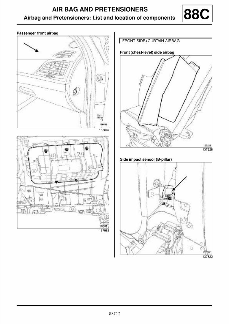
8/6/2019 8 - Electrical Equipment
http://slidepdf.com/reader/full/8-electrical-equipment 239/29488C-2
AIR BAG AND PRETENSIONERS
Airbag and Pretensioners: List and location of components 88CPassenger front airbag
Front (chest-level) side airbag
Side impact sensor (B-pillar)
136699
137981
FRONT SIDE+CURTAIN AIRBAG
137828
137822

8/6/2019 8 - Electrical Equipment
http://slidepdf.com/reader/full/8-electrical-equipment 240/29488C-3
AIR BAG AND PRETENSIONERS
Airbag and Pretensioners: List and location of components 88CSide impact sensor (front side door)
Curtain side airbag
Anti-submarining airbag
Front side seat lap belt pretensioner
137779
B95 or D95 or K95, and FRONT SIDE+CURTAINAIRBAG
137833
D95
137831
B95 or K95
137821

8/6/2019 8 - Electrical Equipment
http://slidepdf.com/reader/full/8-electrical-equipment 241/29488C-4
AIR BAG AND PRETENSIONERS
Airbag and Pretensioners: List and location of components 88CFront seat belt buckle
Rear seat belt buckle
Rear side seat belt
137783
B95 or D95 or K95, and STANDARD
137777
B95
137775

8/6/2019 8 - Electrical Equipment
http://slidepdf.com/reader/full/8-electrical-equipment 242/29488C-5
AIR BAG AND PRETENSIONERS
Airbag and Pretensioners: List and location of components 88C
Rear side seat belt Front side seat belt
Front side seat belt
D95
137827
B95
137817
D95
137791

8/6/2019 8 - Electrical Equipment
http://slidepdf.com/reader/full/8-electrical-equipment 243/29488C-6
AIR BAG AND PRETENSIONERS
Airbag and Pretensioners: List and location of components 88CRear centre seat belt
Inhibitor switch
123314
136699

8/6/2019 8 - Electrical Equipment
http://slidepdf.com/reader/full/8-electrical-equipment 244/29488C-7
AIR BAG AND PRETENSIONERS
Airbag and Pretensioners: Precautions for repair 88C
I - PRECAUTIONS FOR REPAIR
Always replace any pyrotechnic system that has fallenon the ground or shows signs of impact.
Always replace any restraint system that shows dete-rioration (strap damage, damaged appearance parts,cover unclipped, damaged indexing brackets, etc.).
Disconnect the battery:
- before disconnecting a pyrotechnic component (air-bag or pretensioner)
- before removing a pyrotechnic component (airbag or
pretensioner)
- before disconnecting a trigger line (steering columnswitch assembly connection, under-seat connection,etc.)
- before a bodywork operation (removal of the door fit-tings, dent removal, jacking, replacement of non deta-chable components, etc.)
Lock the airbag computer and disconnect thebattery:
- before disconnecting the airbag computer or side im-pact sensors
- before removing the airbag computer or side impactsensors
- before disconnecting the airbag computer line (excepttrigger line) or side impact sensors line
Switch off the ignition:
- before disconnecting an occupant detection compo-nent (inhibitor switch, seatbelt buckling detection con-nector, etc.)
- before removing an occupant detection component(inhibitor switch, seatbelt buckling detection connec-tor, etc.)
- before disconnecting an occupant detection line (inhi-bitor switch, seatbelt buckling detection connector,etc.)
Check the safety systems using the diagnostic tool :
- after an accident,
- after theft or attempted theft of the vehicle,
- before selling a used vehicle.
II - TRIGGERING OF THE SAFETY SYSTEMS
After detection of an impact, the airbag computer is de-finitively locked and the « airbag fault » warning light il-luminates on the instrument panel. The airbagcomputer and the side impact sensors must always bereplaced.
Essential equipment
diagnostic tool
IMPORTANT
All operations on airbag and pretensioner systemsmust be carried out by qualified trained personnel.
The airbags have a pyrotechnic gas generator, withan ignition module and bag which must not beseparated.
The pretensioners have a pyrotechnic gas genera-
tor and an igniter which must, under no circumstan-ces, be separated.
IMPORTANT
Never handle the pyrotechnic systems (pretensio-ners or airbags) near to a source of heat or nakedflame - they may be triggered.
IMPORTANT
In order to prevent interference with the deploymentof the airbags:
- do not fit a cover to the front seats,
- do not place objects in the area of deployment.
IMPORTANT
To eliminate the risk of any accident, do not reusepyrotechnic components.
It is essential to destroy pretensioners or airbagsbefore scrapping a vehicle or a part only (see 88C,Air bag and Pretensioners, Airbags and preten-sioners: Recycling - Destruction, page 88C-9) .

8/6/2019 8 - Electrical Equipment
http://slidepdf.com/reader/full/8-electrical-equipment 245/29488C-8
AIR BAG AND PRETENSIONERS
Airbag and Pretensioners: Precautions for repair 88CIII - DURABILITY OF THE PYROTECHNICCOMPONENTS
The precautions which recommended that pyrotechniccomponents (airbags and pretensioners) were repla-ced 10 years after the registration of the vehicle havenow been lifted.
Pyrotechnical components (airbags and pretensioners)do not therefore require any maintenance.

8/6/2019 8 - Electrical Equipment
http://slidepdf.com/reader/full/8-electrical-equipment 246/29488C-9
AIR BAG AND PRETENSIONERS
Airbags and pretensioners: Recycling - Destruction 88C
a Always use the tooland three kits of adapters (Ele.1287-02),and.
a Use a wiring connector kit 82 00 518 971.
a Attach the wiring connectors 82 00 518 971 to theadapters (Ele. 1287-02) to obtain an adapter foreach colour (green, orange, blue, etc.) (see Wiring:Repair) (Technical Note 6015A, 88A, Wiring).
a Use a battery to power the destruction tool.
I - AIRBAGS
a
a Prepare the adapter corresponding to the airbag tobe destroyed.
aConnect:
- the adapter to the destruction tool,
- the adapter to the airbag.
Essential special tooling
Ele. 1287-02 Set of 2 adapters for airbagand pretensioners destruc-tion tool.
IMPORTANT
To avoid all risk of damage to the systems, applythe safety and cleanliness instructions and opera-tion recommendations before carrying out anyrepair (see 88C, Air bag and Pretensioners , Air-bag and Pretensioners: Precautions for repair,page 88C-7) .
IMPORTANT
To eliminate the risk of any accident, do not reusepyrotechnic components.
It is essential to destroy pretensioners or airbagsbefore scrapping a vehicle or a part only.
WARNING
- Each part is intended for a specific vehicle typeand should not be fitted on another vehicle under
any circumstances. The parts are not interchan-geable.
- Do not trigger pretensioners which are to be retur-ned under warranty because of a faulty stalk. Thismakes analysis of the part by the supplier impossi-ble. Return the defective part to Techline in thepackaging of the new part.
WARNING
The destruction procedure cannot be carried out iflocal regulations require a special procedure whichhas been confirmed and published by the Fault fin-ding, Repair and Procedures Department.
Note:
If triggering is not possible (faulty ignition module)return the part to Techline.
96832
Note:
The airbags must be destroyed outside theworkshop, in an area with sufficient space.
The airbags to be destroyed must be removed.
Note:
If the airbag has two levels of activation (i.e. it isfitted with two connectors), destroy both connec-tors.

8/6/2019 8 - Electrical Equipment
http://slidepdf.com/reader/full/8-electrical-equipment 247/29488C-10
AIR BAG AND PRETENSIONERS
Airbags and pretensioners: Recycling - Destruction 88C
a Put the airbag on two wooden blocks.
a The destruction procedure is carried out in a stack ofold tyres.
a Make sure that the airbag deployment will not behindered.
a Unwind the full length of the wiring for the tool, in or-der to distance it as far away as possible from thepyrotechnic component to be destroyed.
a Connect the two feed wires of the destruction tooltoa battery.
a Destroy the airbag by pressing the two push buttonson the tool simultaneously.
II - PYROTECHNIC PRETENSIONERS AND INERTIAREELS
1 - Destruction of part fitted on the vehicle to bescrapped:
a Move the vehicle outside the workshop.
a Mark the adapter corresponding to the pyrotechniccomponent to be destroyed.
a Connect:
- the destruction toolto the adapter,
- the adapter to the pyrotechnic component.
a Unwind the tool wiring fully, so that you are far enou-gh away from the vehicle (approximately ten metres)when the device is triggered.
a Connect the two feed wires of the destruction tooltoa battery.
a Destroy the pyrotechnic component by pressing thetwo push buttons on the tool simultaneously.
2 - Destruction of part removed from the vehicle:
a Proceed in the same way as for an airbag (in a stackof old tyres).
96834
96835
IMPORTANT
To prevent any risk of an accident when des-troying a pyrotechnic component, check that no-one is in the vicinity.
IMPORTANT
To prevent any risk of an accident when des-troying a pyrotechnic component, check that no-one is in the vicinity.

8/6/2019 8 - Electrical Equipment
http://slidepdf.com/reader/full/8-electrical-equipment 248/29488C-11
AIR BAG AND PRETENSIONERS
Airbag computer: Removal - Refitting
B95 or D95 or K95
88C
REMOVAL
I - REMOVAL PREPARATION OPERATION
a
a Lock the airbag computer by applying the "Before re-
pair procedure" using the diagnostic tool :
- connect the diagnostic tool,
- select « Airbag computer » ,
- go to repair mode,
- display the « before/after repair procedure » for thecomputer selected,
- carry out the operations described in the « Beforerepair procedure » section.
a Disconnect the battery (see 80A, Battery, Battery :Removal - Refitting, page 80A-2) .
a Remove the centre console (see Centre console:Removal - Refitting) (57A, Interior equipment).
a Make a 20 cm cut in the carpet.
a Move aside the soundproofing (1) .
Essential equipment
diagnostic tool
Tightening torquesm
airbag computer nuts 8 N.m
IMPORTANT
To avoid all risk of damage to the systems, apply
the safety and cleanliness instructions and opera-tion recommendations before carrying out any
repair (see 88C, Air bag and Pretensioners , Air-bag and Pretensioners: Precautions for repair,page 88C-7) .
IMPORTANT
To avoid any r isk of triggering when working onor near a pyrotechnic component (airbags or pre-
tensioners), lock the airbag computer using thediagnostic tool.
When this function is activated, all the triggerlines are inhibited and the airbag warning light onthe instrument panel lights up continuously (igni-tion on).
137970
137971

8/6/2019 8 - Electrical Equipment
http://slidepdf.com/reader/full/8-electrical-equipment 249/29488C-12
AIR BAG AND PRETENSIONERS
Airbag computer: Removal - Refitting
B95 or D95 or K95
88C
a Remove the airbag computer protector (2) .
II - OPERATION FOR REMOVAL OF PARTCONCERNED
a Mark the wiring routing.
a Unlock the airbag computer connector (3) .
a Disconnect the airbag computer connector (4) .
a Remove:
- the airbag computer nuts (5) ,
- the airbag computer.
REFITTING
I - REFITTING PREPARATION OPERATION
a parts always to be replaced: Airbag computerprotector (31,02,01,46).
a Always replace the airbag computer mounting nuts.
II - REFITTING OPERATION FOR PART
CONCERNED
a Refit the airbag computer.
a Torque tighten the airbag computer nuts (8 N.m).
137972
137973
WARNING
To prevent any risk of noise, premature wear,short circuits, etc. after the refitting operation,mark the wiring routing and how to connect theconnectors.

8/6/2019 8 - Electrical Equipment
http://slidepdf.com/reader/full/8-electrical-equipment 250/29488C-13
AIR BAG AND PRETENSIONERS
Airbag computer: Removal - Refitting
B95 or D95 or K95
88C
a Refit the wiring in the position marked during remo-val.
Check that the earth wire and the earth terminal arecorrectly positioned.
a Connect the airbag computer connector (4) .
a Lock the airbag computer connector (3) .
III - FINAL OPERATION
a Refit a new airbag computer protector.
a Position the soundproofing.
a Clip the carpet where it was cut using clips (part
number: 77 01 047 751).
a Refit the centre console (see Centre console: Re-
moval - Refitting) (57A, Interior equipment).
a Connect the battery (see 80A, Battery, Battery :Removal - Refitting, page 80A-2) .
a Unlock the airbag computer by applying the "Afterrepair procedure" using the diagnostic tool :
- connect the diagnostic tool,
- select « Airbag computer » ,
- go to repair mode,
- display the « before/after repair procedure » for the
computer selected,- carry out the operations described in the « After re-pair procedure » section.

8/6/2019 8 - Electrical Equipment
http://slidepdf.com/reader/full/8-electrical-equipment 251/29488C-14
AIR BAG AND PRETENSIONERS
Driver's front airbag: Removal - Refitting 88C
REMOVAL
I - REMOVAL PREPARATION OPERATION
a Disconnect the battery (see 80A, Battery, Battery :
Removal - Refitting, page 80A-2) .a Remove:
- the bolts on the cowlings under the steering wheel,
- the cowlings under the steering wheel.
II - OPERATION FOR REMOVAL OF PARTCONCERNED
a Insert a flat screwdriver into the aperture (1) locatedbehind the steering wheel.
a Unclip the driver's front airbag by pushing in the di-
rection of the arrow (2) .
IMPORTANT
To avoid all risk of damage to the systems, applythe safety and cleanliness instructions and opera-
tion recommendations before carrying out anyrepair (see 88C, Air bag and Pretensioners , Air-bag and Pretensioners: Precautions for repair,page 88C-7) .
IMPORTANT
Never leave the driver's front airbag hanging only bythe connectors.
IMPORTANT
Never handle the pyrotechnic systems (pretensio-ners or airbags) near to a source of heat or nakedflame - they may be triggered.
136726
18455

8/6/2019 8 - Electrical Equipment
http://slidepdf.com/reader/full/8-electrical-equipment 252/29488C-15
AIR BAG AND PRETENSIONERS
Driver's front airbag: Removal - Refitting 88C
a Unlock at (3) the driver's front airbag connectors (4) .
a Disconnect the connectors (4) from the driver's frontairbag.
a Remove the driver's front airbag.
REFITTING
I - REFITTING PREPARATION OPERATION
a
II - REFITTING OPERATION FOR PARTCONCERNED
a
a Connect the connectors for the driver's frontal air-bag.
a Lock the driver's front airbag connectors.
a Refit the driver's front airbag onto the steering
wheel.
a Clip on the driver's front airbag.
a Check that the driver's front airbag is properly clip-ped onto the steering wheel:
- try to unclip the driver's front airbag by pushingupwards,
- check the operating clearances of the audible war-ning in the upper section of the driver's front airbagmodule on the steering wheel.
III - FINAL OPERATION
a Refit the covers under the steering wheel.
a Connect the battery (see 80A, Battery, Battery :Removal - Refitting, page 80A-2) .
101920
136725
IMPORTANT
To prevent the any component from being thrownupwards, store the airbag with the inflatablecushion facing upwards.
IMPORTANT
After a seat belt pyrotechnic component is trigge-red, it is essential to replace certain parts (see88C, Air bag and Pretensioners , Airbag andPretensioners: Precautions for repair, page88C-7) .
IMPORTANT
Check that there are no foreign bodies (anti-rota-tion pin of the steering column controls, etc.)between the steering wheel and the driver's frontairbag.
IMPORTANT
To eliminate the risk of any accident, do notreuse pyrotechnic components.
It is essential to destroy pretensioners or airbags
before scrapping a vehicle or a part only (see88C, Air bag and Pretensioners, Airbags andpretensioners: Recycling - Destruction, page88C-9) .

8/6/2019 8 - Electrical Equipment
http://slidepdf.com/reader/full/8-electrical-equipment 253/29488C-16
AIR BAG AND PRETENSIONERS
Driver's front airbag: Removal - Refitting 88CIV - CHECKING AFTER REPAIR
a Switch on the ignition.
a Check that there are no faults on the instrument pa-nel.

8/6/2019 8 - Electrical Equipment
http://slidepdf.com/reader/full/8-electrical-equipment 254/29488C-17
AIR BAG AND PRETENSIONERS
Passenger front airbag: Removal - Refitting 88C
REMOVAL
I - REMOVAL PREPARATION OPERATION
a Disconnect the battery (see 80A, Battery, Battery :Removal - Refitting, page 80A-2) .
a Remove the dashboard (see Dashboard: Removal- Refitting) (57A, Interior equipment).
II - OPERATION FOR REMOVAL OF PARTCONCERNED
a Remove:
- the bolts (1) mounting the passenger front airbagon the dashboard,
- the passenger front airbag.
Tightening torquesm
passenger front airbag
bolts
4 N.m
passenger front airbagbolts on the dashboardcross member
4 N.m
IMPORTANT
To avoid all risk of damage to the systems, applythe safety and cleanliness instructions and opera-tion recommendations before carrying out anyrepair (see 88C, Air bag and Pretensioners , Air-
bag and Pretensioners: Precautions for repair,page 88C-7) .
IMPORTANT
Never handle the pyrotechnic systems (pretensio-ners or airbags) near to a source of heat or nakedflame - they may be triggered.
137981
IMPORTANT
To prevent the any component from being thrownupwards, store the airbag with the inflatablecushion facing upwards.

8/6/2019 8 - Electrical Equipment
http://slidepdf.com/reader/full/8-electrical-equipment 255/29488C-18
AIR BAG AND PRETENSIONERS
Passenger front airbag: Removal - Refitting 88CREFITTING
I - REFITTING PREPARATION OPERATION
a
a parts always to be replaced: Passenger's frontairbag mounting on dashboard (31,02,01,44).
a parts always to be replaced: Passenger's frontairbag mounting on dashboard cross member(31,02,01,45).
II - REFITTING OPERATION FOR PARTCONCERNED
aRefit the passenger front airbag on the dashboardusing the centring devices (2) .
a Torque tighten the passenger front airbag bolts (4N.m).
III - FINAL OPERATION
a Refit the dashboard (see Dashboard: Removal -Refitting) (57A, Interior equipment).
a Torque tighten the passenger front airbag bolts
on the dashboard cross member (4 N.m).
a Connect the passenger front airbag connectors (3) .
a Lock the passenger front airbag connectors (3) .
a Connect the battery (see 80A, Battery, Battery :Removal - Refitting, page 80A-2) .
IV - CHECKING AFTER REPAIR
a Switch on the ignition.
a Check that there are no faults on the instrument pa-nel.
IMPORTANT
After a seat belt pyrotechnic component is trigge-red, it is essential to replace certain parts (see88C, Air bag and Pretensioners, Airbag andPretensioners: Precautions for repair, page88C-7) .
IMPORTANT
When the passenger front airbag is triggered, theconsequent damage caused to the mountings
always requires the dashboard to be replaced.Affix the label warning against fitting a rear-facingchild seat on the front passenger seat to the pas-senger side of the dashboard.
137981
137744
IMPORTANT
To eliminate the risk of any accident, do notreuse pyrotechnic components.
It is essential to destroy pretensioners or airbagsbefore scrapping a vehicle or a part only (see88C, Air bag and Pretensioners, Airbags and
pretensioners: Recycling - Destruction, page88C-9) .

8/6/2019 8 - Electrical Equipment
http://slidepdf.com/reader/full/8-electrical-equipment 256/29488C-19
AIR BAG AND PRETENSIONERS
Front (chest) side airbag: Removal - Refitting
FRONT SIDE+CURTAIN AIRBAG
88C
The front side (chest-level) airbag is fixed to the lowersection of the seatback of each front seat on the doorside.
When the airbag is deployed, it tears the module coverand the seatback trim.
REMOVAL
I - REMOVAL PREPARATION OPERATION
a Disconnect the battery (see 80A, Battery, Battery :Removal - Refitting, page 80A-2) .
a Remove:
- the front seat (see Complete front seat: Removal- Refitting) (75A, Front seat frames and runners),
- the front seatback trim partially (see Front seat-
back trim: Removal - Refitting) (77A, Front seattrim).
II - OPERATION FOR REMOVAL OF PARTCONCERNED
a Mark the wiring routing on the seat frame.
a Unlock the front side (chest-level) airbag connector(1) at (2) .
Tightening torquesm
front (chest-level) side
airbag nuts
8 N.m
IMPORTANT
To avoid all risk of damage to the systems, applythe safety and cleanliness instructions and opera-tion recommendations before carrying out anyrepair (see 88C, Air bag and Pretensioners , Air-bag and Pretensioners: Precautions for repair,page 88C-7) .
IMPORTANT
Never handle the pyrotechnic systems (pretensio-ners or airbags) near to a source of heat or nakedflame - they may be triggered.
101920
WARNING
To prevent any risk of noise, premature wear,
short circuits, etc. after the refitting operation,mark the wiring routing and how to connect theconnectors.

8/6/2019 8 - Electrical Equipment
http://slidepdf.com/reader/full/8-electrical-equipment 257/29488C-20
AIR BAG AND PRETENSIONERS
Front (chest) side airbag: Removal - Refitting
FRONT SIDE+CURTAIN AIRBAG
88C
a Disconnect the connector (3) from the front side(chest-level) airbag.
a Loosen the nuts (4) of the front (chest-level) side air-bag.
a Remove:
- the « front (chest-level) side airbag - concentrator »assembly,
- the front (chest-level) side airbag (5) from the con-centrator (6) ,
- the front side (chest-level) airbag.
REFITTING
I - REFITTING PREPARATION OPERATION
a
a parts always to be replaced: Front (chest) sideairbag (31,02,01,37).
a Always replace the nuts for the front (chest-level)side airbag.
137830
137829
137828
IMPORTANT
After a pyrotechnic component is triggered, it isessential to replace certain parts (see 88C , Airbag and Pretensioners, Airbag and Pretensio-ners: Precautions for repair, page 88C-7) .
IMPORTANT
To ensure proper mounting of the chest-levelside airbag igniter, never refit a chest-level sideairbag that has been removed.

8/6/2019 8 - Electrical Equipment
http://slidepdf.com/reader/full/8-electrical-equipment 258/29488C-21
AIR BAG AND PRETENSIONERS
Front (chest) side airbag: Removal - Refitting
FRONT SIDE+CURTAIN AIRBAG
88C
II - REFITTING OPERATION FOR PARTCONCERNED
a Refit:
- the front (chest-level) side airbag in the concentra-tor,
- the « front (chest-level) side airbag - concentrator »assembly.
a Torque tighten the front (chest-level) side airbagnuts (8 N.m).
a Refit the wiring in the position marked during remo-val.
a Connect the front side (chest-level) airbag connec-tor.
a Lock the front side (chest-level) airbag connector.
III - FINAL OPERATION
a Refit:
- the front seat back trim (see Front seatback trim:Removal - Refitting) (77A, Front seat trim),
- the front seat (see Complete front seat: Removal- Refitting) (75A, Front seat frames and runners).
a Connect the battery (see 80A, Battery, Battery :Removal - Refitting, page 80A-2) .
IV - CHECKING AFTER REPAIR
a Switch on the ignition.
a Check that there are no faults on the instrument pa-nel.
WARNING
To prevent damage to the wiring harness whenrefitting, observe the original routing.
IMPORTANTTo eliminate the risk of any accident, do notreuse pyrotechnic components.
It is essential to destroy pretensioners or airbagsbefore scrapping a vehicle or a part only (see88C, Air bag and Pretensioners, Airbags andpretensioners: Recycling - Destruction, page88C-9) .

8/6/2019 8 - Electrical Equipment
http://slidepdf.com/reader/full/8-electrical-equipment 259/29488C-22
AIR BAG AND PRETENSIONERS
Side curtain airbag: Removal - Refitting
B95 or D95 or J95 or K95, and FRONT SIDE+CURTAIN AIRBAG
88C
REMOVAL
I - REMOVAL PREPARATION OPERATION
a Disconnect the battery (see 80A, Battery, Battery :
Removal - Refitting, page 80A-2) .
a Remove the headlining (see Headlining: Removal -Refitting) (71A, Body internal trim).
II - OPERATION FOR REMOVAL OF PARTCONCERNED
a Unlock the connector (1) from the side curtain airbagat (2) .
a Disconnect the connector (2) from the side curtainairbag.
Tightening torquesm
bolt of the side curtain
airbag bracket
8 N.m
IMPORTANT
To avoid all risk of damage to the systems, applythe safety and cleanliness instructions and opera-tion recommendations before carrying out anyrepair (see 88C, Air bag and Pretensioners , Air-bag and Pretensioners: Precautions for repair,
page 88C-7) .
IMPORTANT
Never handle the pyrotechnic systems (pretensio-ners or airbags) near to a source of heat or nakedflame - they may be triggered.
101920
137816

8/6/2019 8 - Electrical Equipment
http://slidepdf.com/reader/full/8-electrical-equipment 260/29488C-23
AIR BAG AND PRETENSIONERS
Side curtain airbag: Removal - Refitting
B95 or D95 or J95 or K95, and FRONT SIDE+CURTAIN AIRBAG
88C
a Remove:
- the front strap (3) ,
- the plastic rivets (4) .a Cut the cover (5) and unroll the side airbag curtain.
a Cut the side curtain airbag clips (6) .
a Bend the lower bracket of the clips.
a Unclip the clips.
a Remove the bracket (7) of the side curtain airbag.
a Unclip the bracket of the side curtain airbag.
a Remove the side curtain airbag.
137781
137814
137815
137816

8/6/2019 8 - Electrical Equipment
http://slidepdf.com/reader/full/8-electrical-equipment 261/29488C-24
AIR BAG AND PRETENSIONERS
Side curtain airbag: Removal - Refitting
B95 or D95 or J95 or K95, and FRONT SIDE+CURTAIN AIRBAG
88C
REFITTING
I - REFITTING PREPARATION OPERATION
a
a parts always to be replaced: Side curtain airbag(31,02,01,40).
a parts always to be replaced: Side curtain airbagbolt (31,02,01,41).
II - REFITTING OPERATION FOR PARTCONCERNED
a Refit a new side curtain airbag by fully engaging the
indexing bracket in the side roof rail lining.a Torque tighten the bolt of the side curtain airbag
bracket (8 N.m).
a Engage the front anchor strap in the hole of thewindscreen pillar (8) .
a Clip the strap onto the two clips (9) of the winds-creen pillar.
a Clip the clips (10) of the side airbag curtain in theside roof rail, passing under the support (11) .
a Refit the plastic rivets in the clips (10) .
IMPORTANT
After a seat belt pyrotechnic component is trigge-red, it is essential to replace certain parts (see88C, Air bag and Pretensioners, Airbag andPretensioners: Precautions for repair, page88C-7) .
IMPORTANT
In order to ensure the side curtain airbag clips
hold, never refit a side curtain airbag which hasbeen removed.
137781
137814

8/6/2019 8 - Electrical Equipment
http://slidepdf.com/reader/full/8-electrical-equipment 262/29488C-25
AIR BAG AND PRETENSIONERS
Side curtain airbag: Removal - Refitting
B95 or D95 or J95 or K95, and FRONT SIDE+CURTAIN AIRBAG
88C
a Clip the three clips (13) onto the side roof rail, pas-sing under the rear support (12) .
a Clip the two clips (15) onto the side roof rail, passingunder the rear support (14) .
a Connect the side curtain airbag connector.
a Lock the side curtain airbag connector.
a Check that the welding line of the flexible cover isoriented laterally upwards over the entire length withno folds or twists.
III - FINAL OPERATION
a Refit the headlining (see Headlining: Removal -Refitting) (71A, Body internal trim).
a
Connect the battery (see 80A, Battery, Battery :Removal - Refitting, page 80A-2) .
IV - CHECKING AFTER REPAIR
a Switch on the ignition.
a Check that there are no faults on the instrument pa-nel.
B95 or J95 or K95
137815
D95
137815
IMPORTANT
To eliminate the risk of any accident, do notreuse pyrotechnic components.
It is essential to destroy pretensioners or airbagsbefore scrapping a vehicle or a part only (see88C, Air bag and Pretensioners, Airbags and
pretensioners: Recycling - Destruction, page88C-9) .
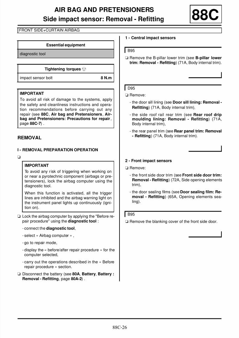
8/6/2019 8 - Electrical Equipment
http://slidepdf.com/reader/full/8-electrical-equipment 263/29488C-26
AIR BAG AND PRETENSIONERS
Side impact sensor: Removal - Refitting
FRONT SIDE+CURTAIN AIRBAG
88C
REMOVAL
I - REMOVAL PREPARATION OPERATION
a
a Lock the airbag computer by applying the "Before re-pair procedure" using the diagnostic tool :
- connect the diagnostic tool,
- select « Airbag computer » ,- go to repair mode,
- display the « before/after repair procedure » for thecomputer selected,
- carry out the operations described in the « Beforerepair procedure » section.
a Disconnect the battery (see 80A, Battery, Battery :Removal - Refitting, page 80A-2) .
1 - Central impact sensors
aRemove the B-pillar lower trim (see B-pillar lowertrim: Removal - Refitting) (71A, Body internal trim).
a Remove:
- the door sill lining (see Door sill lining: Removal -
Refitting) (71A, Body internal trim),
- the side roof rail rear trim (see Rear roof drip
moulding lining: Removal - Refitting) (71A,Body internal trim),
- the rear panel trim (see Rear panel trim: Removal- Refitting) (71A, Body internal trim).
2 - Front impact sensors
a Remove:
- the front side door trim (see Front side door trim:Removal - Refitting) (72A, Side opening elementstrim),
- the door sealing films (see Door sealing film: Re-moval - Refitting) (65A, Opening elements sea-ling).
a Remove the blanking cover of the front side door.
Essential equipment
diagnostic tool
Tightening torquesm
impact sensor bolt 8 N.m
IMPORTANT
To avoid all risk of damage to the systems, apply
the safety and cleanliness instructions and opera-tion recommendations before carrying out anyrepair (see 88C, Air bag and Pretensioners , Air-
bag and Pretensioners: Precautions for repair,page 88C-7) .
IMPORTANT
To avoid any r isk of triggering when working on
or near a pyrotechnic component (airbags or pre-tensioners), lock the airbag computer using thediagnostic tool.
When this function is activated, all the triggerlines are inhibited and the airbag warning light onthe instrument panel lights up continuously (igni-tion on).
B95
D95
B95

8/6/2019 8 - Electrical Equipment
http://slidepdf.com/reader/full/8-electrical-equipment 264/29488C-27
AIR BAG AND PRETENSIONERS
Side impact sensor: Removal - Refitting
FRONT SIDE+CURTAIN AIRBAG
88C
II - REMOVAL OPERATION FOR PARTCONCERNED
1 - Central impact sensors
a Disconnect the central impact sensor connector (1) .
a Undo the central impact sensor bolt (2) by six turns.
a Slide the impact sensor towards the top of the B-pillar (3) .
a Remove the impact sensor from the B-pillar.
2 - Front impact sensors
a Undo the front impact sensor bolt (4) by six turns.
a Move the impact sensor towards the top of the frontdoor.
a Disconnect the front impact sensor connector (5) .
a Remove the impact sensor from the front door.
137822
B95
137779

8/6/2019 8 - Electrical Equipment
http://slidepdf.com/reader/full/8-electrical-equipment 265/29488C-28
AIR BAG AND PRETENSIONERS
Side impact sensor: Removal - Refitting
FRONT SIDE+CURTAIN AIRBAG
88C
a Undo the front impact sensor bolt (6) by six turns.
a Slide the impact sensor towards the top of the frontdoor (7) .
a Disconnect the front impact sensor connector (8) .
a Remove the impact sensor from the front door.
REFITTING
I - REFITTING PREPARATION OPERATION
aparts always to be replaced: Side impact sen-sors (31,02,01,21).
II - REFITTING OPERATION FOR PARTCONCERNED
1 - Central impact sensors
a Connect the central impact sensor connector.
a Refit the side impact sensor in the slot on the B-pillar.
a Slide the side impact sensor down to the bottom ofthe slot.
a Torque tighten the impact sensor bolt (8 N.m).
2 - Front impact sensors
a Connect the front impact sensor connector.
a Refit the impact sensor on the front door.
a Torque tighten the impact sensor bolt 8 N.m.
III - FINAL OPERATION
1 - Central impact sensors
a Refit the B-pillar lower trim (see B-pillar lower trim:Removal - Refitting) (71A, Body internal trim).
a Refit:
- the rear panel trim (see Rear panel trim: Removal- Refitting) (71A, Body internal trim),
- the side roof rail rear trim (see Rear roof dripmoulding lining: Removal - Refitting) (71A,Body internal trim),
- the door sill lining (see Door sill lining: Removal -Refitting) (71A, Body internal trim).
2 - Front impact sensors
a Refit the blanking cover of the front side door.
a Refit:
- the door sealing films (see Door sealing film: Re-moval - Refitting) (65A, Opening element sea-ling),
- the front side door trim (see Front side door trim:Removal - Refitting) (72A, Side opening elementstrim).
a Connect the battery (see 80A, Battery, Battery :Removal - Refitting, page 80A-2) .
a Unlock the airbag computer by applying the "Afterrepair procedure" using the diagnostic tool :
- connect the diagnostic tool,
D95
137788
B95
D95
B95

8/6/2019 8 - Electrical Equipment
http://slidepdf.com/reader/full/8-electrical-equipment 266/29488C-29
AIR BAG AND PRETENSIONERS
Side impact sensor: Removal - Refitting
FRONT SIDE+CURTAIN AIRBAG
88C
- select « Airbag computer » ,
- go to repair mode,
- display the « before/after repair procedure » for the
computer selected,- carry out the operations described in the « After re-pair procedure » section.

8/6/2019 8 - Electrical Equipment
http://slidepdf.com/reader/full/8-electrical-equipment 267/29488C-30
AIR BAG AND PRETENSIONERS
Anti-submarining airbag: Removal - Refitting
D95
88C
REMOVAL
I - REMOVAL PREPARATION OPERATION
a Disconnect the battery (see 80A, Battery, Battery :
Removal - Refitting, page 80A-2) .
a Remove:
- the front seat (see Complete front seat: Removal- Refitting) (75A, Front seat frames and runners),
- the front seat base trim (see Front seat base trim:Removal - Refitting) (77A, Front seat trim).
II - OPERATION FOR REMOVAL OF PARTCONCERNED
a Mark the wiring routing on the seat frame.
a Unlock at (1) the anti-submarining airbag connector(2) .
Tightening torquesm
anti-submarining airbag
nuts
5 N.m
IMPORTANT
To avoid all risk of damage to the systems, applythe safety and cleanliness instructions and opera-tion recommendations before carrying out anyrepair (see 88C, Air bag and Pretensioners , Air-bag and Pretensioners: Precautions for repair,
page 88C-7) .
IMPORTANT
Never handle the pyrotechnic systems (pretensio-ners or airbags) near to a source of heat or nakedflame - they may be triggered.
101920
WARNING
To prevent any risk of noise, premature wear,
short circuits, etc. after the refitting operation,mark the wiring routing and how to connect theconnectors.

8/6/2019 8 - Electrical Equipment
http://slidepdf.com/reader/full/8-electrical-equipment 268/29488C-31
AIR BAG AND PRETENSIONERS
Anti-submarining airbag: Removal - Refitting
D95
88C
a Disconnect the anti-submarining airbag connector(2) .
a Remove:
- the anti-submarining airbag nuts (3) ,
- the anti-submarining airbag.
REFITTING
I - REFITTING PREPARATION OPERATION
a
a parts always to be replaced: Anti-submariningairbag (31,02,01,35).
a Always replace the nuts of the anti-submarining air-bag.
II - REFITTING OPERATION FOR PARTCONCERNED
aRefit the anti-submarining airbag on the front seatbase.
a Torque tighten the anti-submarining airbag nuts(5 N.m).
a Refit the wiring in the position marked during remo-val.
a Connect the anti-submarining airbag connector.
a Lock the anti-submarining airbag connector.
III - FINAL OPERATION
a Refit:
- the front seat base trim (see Front seat base trim:Removal - Refitting) (77A, Front seat trim),
- the front seat (see Complete front seat: Removal- Refitting) (75A, Front seat frames and runners).
a
a Connect the battery (see 80A, Battery, Battery :Removal - Refitting, page 80A-2) .
IV - CHECKING AFTER REPAIR
a Switch on the ignition.
a Check that there are no faults on the instrument pa-nel.
137832
IMPORTANT
After a seat belt pyrotechnic component is trigge-red, it is essential to replace certain parts (see
88C, Air bag and Pretensioners, Airbag and
Pretensioners: Precautions for repair, page88C-7) .
WARNING
To prevent damage to the wiring harness whenrefitting, observe the original routing.
IMPORTANT
To eliminate the risk of any accident, do notreuse pyrotechnic components.
It is essential to destroy pretensioners or airbagsbefore scrapping a vehicle or a part only (see88C, Air bag and Pretensioners, Airbags andpretensioners: Recycling - Destruction, page88C-9) .

8/6/2019 8 - Electrical Equipment
http://slidepdf.com/reader/full/8-electrical-equipment 269/29488C-32
AIR BAG AND PRETENSIONERS
Inhibitor switch: Removal - Refitting 88C
REMOVAL
OPERATION FOR REMOVAL OF PARTCONCERNED
a Switch off the ignition.
a Remove the side panel using the tool (Car. 1363) (1).
a Disconnect inhibitor switch connector.
a Unclip the inhibitor switch from the side panel at (2) .
REFITTING
I - REFITTING OPERATION FOR PARTCONCERNED
a Clip the inhibitor switch onto the side panel.
a Connect the inhibitor switch connector.
a Refit the side panel.
II - FINAL OPERATION
a Switch on the ignition.
a Check:
- the operation of the deactivation switch,
- the « airbag OFF » warning light on the instrument
panel.
Essential special tooling
Car. 1363 Set of trim removal levers.
137963
137988

8/6/2019 8 - Electrical Equipment
http://slidepdf.com/reader/full/8-electrical-equipment 270/29488C-33
AIR BAG AND PRETENSIONERS
Front seat lap belt pretensioner: Removal - Refitting
B95 or J95 or K95
88C
REMOVAL
I - REMOVAL PREPARATION OPERATION
a Disconnect the battery (see 80A, Battery, Battery :
Removal - Refitting, page 80A-2) .
a Remove:
- the front seat (see Complete front seat: Removal- Refitting) (75A, Front seat frames and runners),
- the front seat lower cover (see Front seat lowercover: Removal - Refitting) (77A, Front seat trim).
II - OPERATION FOR REMOVAL OF PARTCONCERNED
a Mark the wiring routing on the seat frame.
a Unlock (1) the connector (2) of the front seat lap beltpretensioner.
a Disconnect the connector (2) of the front seat lapbelt pretensioner.
a Remove:
- the bolt (3) of the front seat lap belt pretensioner,
- the front seat lap belt pretensioner.
Tightening torquesm
bolt of the front seat lap
belt pretensioner
25 N.m
IMPORTANT
To avoid all risk of damage to the systems, applythe safety and cleanliness instructions and opera-tion recommendations before carrying out anyrepair (see 88C, Air bag and Pretensioners , Air-bag and Pretensioners: Precautions for repair,
page 88C-7) .
IMPORTANT
Never handle the pyrotechnic systems (pretensio-ners or airbags) near to a source of heat or nakedflame - they may be triggered.
101920
WARNING
To prevent any risk of noise, premature wear,
short circuits, etc. after the refitting operation,mark the wiring routing and how to connect theconnectors.
137821

8/6/2019 8 - Electrical Equipment
http://slidepdf.com/reader/full/8-electrical-equipment 271/29488C-34
AIR BAG AND PRETENSIONERS
Front seat lap belt pretensioner: Removal - Refitting
B95 or J95 or K95
88C
REFITTING
I - REFITTING PREPARATION OPERATION
a
a Always replace the bolt of the front seat lap belt pre-tensioner.
II - REFITTING OPERATION FOR PARTCONCERNED
a Refit the front seat lap belt pretensioner by positio-ning the anchor point (4) in the seat base frame.
a Torque tighten the bolt of the front seat lap beltpretensioner (25 N.m).
aRefit the wiring in the position marked during remo-val.
a Connect the connector of the front seat lap belt pre-tensioner.
a Lock the connector of the front seat lap belt preten-sioner.
III - FINAL OPERATION
a Refit:
- the front seat lower cover (see Front seat lowercover: Removal - Refitting) (77A, Front seat trim),
- the front seat (see Complete front seat: Removal- Refitting) (75A, Front seat frames and runners).
a Connect the battery (see 80A, Battery, Battery :Removal - Refitting, page 80A-2) .
IV - CHECKING AFTER REPAIR
a Switch on the ignition.
a Check that there are no faults on the instrument pa-nel.
IMPORTANT
After a seat belt pyrotechnic component is trigge-red, it is essential to replace certain parts (see88C, Air bag and Pretensioners, Airbag andPretensioners: Precautions for repair, page88C-7) .
137821
IMPORTANT
To eliminate the risk of any accident, do notreuse pyrotechnic components.
It is essential to destroy pretensioners or airbagsbefore scrapping a vehicle or a part only (see88C, Air bag and Pretensioners, Airbags andpretensioners: Recycling - Destruction, page88C-9) .

8/6/2019 8 - Electrical Equipment
http://slidepdf.com/reader/full/8-electrical-equipment 272/29488C-35
AIR BAG AND PRETENSIONERS
Front seat belt buckle: Removal - Refitting 88C
REMOVAL
I - REMOVAL PREPARATION OPERATION
a Position the vehicle on a two-post lift (see Vehicle:
Towing and lifting) (02A, Lifting equipment).
a Disconnect the battery (see 80A, Battery, Battery :
Removal - Refitting, page 80A-2) .
a Remove the front seat (see Complete front seat:
Removal - Refitting) (75A, Front seat frames and
runners).
II - OPERATION FOR REMOVAL OF PARTCONCERNED
a Disconnect the font seat belt buckle connector (1) .
a Unclip the front seat belt buckle wiring at (2) .
a Remove:
- the bolt (3) from the front seat belt buckle,
- the front seat belt buckle.
REFITTING
I - REFITTING PREPARATION OPERATION
a Always replace the bolt of the front seat belt buckle.
II - REFITTING OPERATION FOR PARTCONCERNED
a Refit the front seat belt buckle.
a Torque tighten the bolt of the front seat belt buc-kle (25 N.m).
a Clip on the front seat belt buckle wiring.
a Connect the front seat belt buckle connector.
a Check that the front seat belt buckle connector is
properly connected by pulling the wiring harnessdownwards with a force of between 10 N and 30 N.
III - FINAL OPERATION
a Refit the front seat (see Complete front seat: Re-moval - Refitting) (75A, Front seat frames and run-ners).
a Connect the battery (see 80A, Battery, Battery :Removal - Refitting, page 80A-2) .
IV - CHECKING AFTER REPAIR
a Switch on the ignition
a Check that the warning light on the display or on theinstrument panel illuminates.
a Fasten the front seat belts.
a Check that the warning light on the display or on theinstrument panel goes out.
Tightening torquesm
bolt of the front seat belt
buckle
25 N.m
137783

8/6/2019 8 - Electrical Equipment
http://slidepdf.com/reader/full/8-electrical-equipment 273/29488C-36
AIR BAG AND PRETENSIONERS
Rear seat belt buckle: Removal - Refitting
D95 or K95 – B95, and STANDARD
88C
REMOVAL
I - REMOVAL PREPARATION OPERATION
a Switch off the ignition.
a Remove the rear bench seat base (see Rear bench
seat base: Removal - Refitting) (76A, Rear seatframes and runners).
Tightening torquesm
bolts of the rear seat
belt buckles
21 N.m

8/6/2019 8 - Electrical Equipment
http://slidepdf.com/reader/full/8-electrical-equipment 274/29488C-37
AIR BAG AND PRETENSIONERS
Rear seat belt buckle: Removal - Refitting
D95 or K95 – B95, and STANDARD
88C
II - OPERATION FOR REMOVAL OF PARTCONCERNED
a Mark the routing of the wiring of the rear seat beltbuckle connectors.
a Disconnect the connectors (1) of the rear seat beltbuckles.
a Remove:
- the bolts (2) from the rear seat belt buckles,
- the rear seat belt buckles (3) and (4) .
a
REFITTING
I - REFITTING PREPARATION OPERATION
a parts always to be replaced: Rear seat belt buc-kle bolt (31,02,01,51).
II - REFITTING OPERATION FOR PARTCONCERNED
a Refit the rear seat belt buckles by inserting the lugsin the floor holes.
a Torque tighten the bolts of the rear seat belt buc-kles (21 N.m).
a Refit the wiring of the rear seat belt buckle connec-tors.
a Connect the connectors of the rear seat belt buc-kles.
III - FINAL OPERATION
a Refit the rear bench seat base (see Rear benchseat base: Removal - Refitting) (76A, Rear seatframes and runners).
IV - CHECKING AFTER REPAIR
a Switch on the ignition.
a Check that the warning light on the display or on theinstrument panel illuminates.
a Fasten the rear seat belts.
137776
137777
WARNING
To prevent any risk of noise, premature wear,short circuits, etc. after the refitting operation,mark the wiring routing and how to connect theconnectors.
Note:
the bolt of the buckle (3) also secures the rearcentre seat belt.
Note:
the bolt of the buckle (3) also secures the rearcentre seat belt.
Note:
Check that the wiring is not jammed between thefloor and the buckle fitting.

8/6/2019 8 - Electrical Equipment
http://slidepdf.com/reader/full/8-electrical-equipment 275/29488C-38
AIR BAG AND PRETENSIONERS
Rear seat belt buckle: Removal - Refitting
D95 or K95 – B95, and STANDARD
88C
a Check that the warning light on the display or on theinstrument panel goes out.
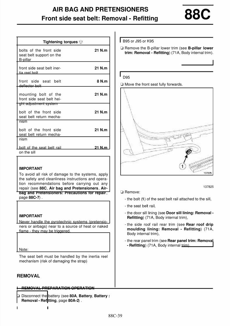
8/6/2019 8 - Electrical Equipment
http://slidepdf.com/reader/full/8-electrical-equipment 276/29488C-39
AIR BAG AND PRETENSIONERS
Front side seat belt: Removal - Refitting 88C
REMOVAL
I - REMOVAL PREPARATION OPERATION
a Disconnect the battery (see 80A, Battery, Battery :Removal - Refitting, page 80A-2) .
a Remove the B-pillar lower trim (see B-pillar lowertrim: Removal - Refitting) (71A, Body internal trim).
a Move the front seat fully forwards.
a Remove:
- the bolt (1) of the seat belt rail attached to the sill,
- the seat belt rail,
- the door sill lining (see Door sill lining: Removal -Refitting) (71A, Body internal trim),
- the side roof rail rear trim (see Rear roof drip
moulding lining: Removal - Refitting) (71A,Body internal trim),
- the rear panel trim (see Rear panel trim: Removal- Refitting) (71A, Body internal trim).
Tightening torquesm
bolts of the front side
seat belt support on theB-pillar
21 N.m
front side seat belt iner-tia reel bolt
21 N.m
front side seat beltdeflector bolt
8 N.m
mounting bolt of thefront side seat belt hei-ght adjustment system
21 N.m
bolt of the front sideseat belt return mecha-nism
21 N.m
bolt of the front sideseat belt return mecha-nism
21 N.m
bolt of the seat belt railon the sill
21 N.m
IMPORTANT
To avoid all risk of damage to the systems, applythe safety and cleanliness instructions and opera-tion recommendations before carrying out anyrepair (see 88C, Air bag and Pretensioners , Air-bag and Pretensioners: Precautions for repair,page 88C-7) .
IMPORTANT
Never handle the pyrotechnic systems (pretensio-ners or airbags) near to a source of heat or nakedflame - they may be triggered.
Note:
The seat belt must be handled by the inertia reelmechanism (risk of damaging the strap)
B95 or J95 or K95
D95
137825

8/6/2019 8 - Electrical Equipment
http://slidepdf.com/reader/full/8-electrical-equipment 277/29488C-40
AIR BAG AND PRETENSIONERS
Front side seat belt: Removal - Refitting 88CII - OPERATION FOR REMOVAL OF PARTCONCERNED
a Unclip the front side seat belt from the lap belt pre-tensioner at (2) using a flat-blade screwdriver.
a Remove:
- the cover (3) of the bolt of the front side seat beltreturn mechanism,
- the bolt (4) of the front side seat belt return mecha-nism,
- the front side seat belt return mechanism.
B95 or J95 or K95
136727
137455
137457

8/6/2019 8 - Electrical Equipment
http://slidepdf.com/reader/full/8-electrical-equipment 278/29488C-41
AIR BAG AND PRETENSIONERS
Front side seat belt: Removal - Refitting 88C
a Remove:
- the cover (5) of the bolt of the front side seat beltreturn mechanism,
- the bolt (6) of the front side seat belt return mecha-nism,
a If necessary,
Remove the height adjustment system of the frontside seat belt by sliding it upwards.
a Remove:
- the bolt (7) of the front side seat belt deflector,
- the front side seat belt deflector.
D95
137792
137793
B95 or J95 or K95
B95 or K95
137456

8/6/2019 8 - Electrical Equipment
http://slidepdf.com/reader/full/8-electrical-equipment 279/29488C-42
AIR BAG AND PRETENSIONERS
Front side seat belt: Removal - Refitting 88C
a Unclip the front side seat belt deflector towards (8) .
a Remove the front side seat belt deflector towards (9).
a Unlock at (10) the connector (11) of the front side
seat belt inertia reel.
a Disconnect the connector (11) of the front side seatbelt inertia reel.
a Remove:
- the front side seat belt inertia reel bolt (12) ,
- the front side seat belt.
a
D95 or J95
137794
101920
B95 or J95 or K95
137817
Note:
Do not touch the bolts (13) ; they secure the frontside seat belt support on the B-pillar.

8/6/2019 8 - Electrical Equipment
http://slidepdf.com/reader/full/8-electrical-equipment 280/29488C-43
AIR BAG AND PRETENSIONERS
Front side seat belt: Removal - Refitting 88C
a Disconnect the connector (11) of the front side seatbelt inertia reel.
a Remove:
- the front side seat belt inertia reel bolt (14) ,
- the front side seat belt.
a
REFITTING
I - REFITTING PREPARATION OPERATION
a
a parts always to be replaced: Front seat belt iner-tia reel bolt (31,02,01,49).
a Always replace the bolts of front side seat belt returnmechanism.
a Always replace the bolt of the front side seat belt rail.
a Always replace the bolt of the front side seat belt de-flector.
II - REFITTING OPERATION FOR PARTCONCERNED
a If removing or replacing the front side seat belt sup-port on the B-pillar,
Torque tighten the bolts of the front side seat beltsupport on the B-pillar (21 N.m).
a Position the indexing brackets of the front side seatbelt inertia reel in the notches of the front side seatbelt support
a Refit the front side seat belt.
a Torque tighten the front side seat belt inertia reelbolt (21 N.m).
a Connect the connector of the front side seat beltinertia reel.
a Lock the connector of the front side seat belt inertiareel.
a Refit the front side seat belt deflector in the holes ofthe B-pillar.
a Torque tighten the front side seat belt deflectorbolt (8 N.m).
a Insert the wire of the belt return mechanism on thefront side seat belt in the holes of the B-pillar whilelocking 1/8 of a turn.
D95
137791
Note:
Do not touch the bolts (15) ; they secure the frontside seat belt support on the B-pillar.
IMPORTANT
After a seat belt pyrotechnic component is trigge-red, it is essential to replace certain parts (see88C, Air bag and Pretensioners, Airbag andPretensioners: Precautions for repair, page88C-7) .
D95
B95 or K95
B95 or K95
D95 or J95

8/6/2019 8 - Electrical Equipment
http://slidepdf.com/reader/full/8-electrical-equipment 281/29488C-44
AIR BAG AND PRETENSIONERS
Front side seat belt: Removal - Refitting 88C
a If removing or replacing the height adjustment sys-
tem of the front side seat belt,
Engage the lower pre-retaining bracket of the frontside seat belt height adjustment system in the slot in
the B-pillar lining by sliding it downwards.
a Torque tighten the mounting bolt of the front side
seat belt height adjustment system (21 N.m)
a
a Refit the front side seat belt return mechanism onthe height adjustment system of the front side seat
belt.
a Torque tighten the bolt of the front side seat beltreturn mechanism (21 N.m).
a Refit the cover of the bolt of the front side seat beltreturn mechanism.
a
a Refit the front side seat belt return mechanism on
the bodywork.
a Torque tighten the bolt of the front side seat beltreturn mechanism (21 N.m).
a Refit the cover of the bolt of the front side seat belt
return mechanism.
a
a Clip the front side seat belt onto the lap belt preten-sioner.
a
a Refit the front side seat belt on the seat belt rail.
III - FINAL OPERATION
a Refit the B-pillar lower trim (see B-pillar lower trim:Removal - Refitting) (71A, Body internal trim).
a Refit:
- the rear panel trim (see Rear panel trim: Removal- Refitting) (71A, Body internal trim),
- the side roof rail rear trim (see Rear roof dripmoulding lining: Removal - Refitting) (71A,Body internal trim),
- the seat belt rail attached to the sill.
a Torque tighten the bolt of the seat belt rail on thesill (21 N.m).
B95 or J95 or K95
Note:
Check that the seat belt is not twisted betweenthe inertia reel and the front side seat belt returnmechanism.
D95
Note:
Check that the seat belt is not twisted betweenthe inertia reel and the front side seat belt returnmechanism.
B95 or J95 or K95
Note:
Check that the seat belt is not twisted betweenthe front side seat belt return mechanism and thelap belt pretensioner.
D95
Note:
Check that the seat belt is not twisted betweenthe front side seat belt return mechanism and theseat belt rail attached to the sill.
B95
D95

8/6/2019 8 - Electrical Equipment
http://slidepdf.com/reader/full/8-electrical-equipment 282/29488C-45
AIR BAG AND PRETENSIONERS
Front side seat belt: Removal - Refitting 88Ca Connect the battery (see 80A, Battery, Battery :
Removal - Refitting, page 80A-2) .
IV - CHECKING AFTER REPAIR
a Check the correct operation by unrolling the frontside seat belt 300 mm and letting it return two times.
a Check that the front side seat belt locks correctly bypulling the front side seat belt strap with increasingspeed 200 to 300 mm maximum until the inertia reellocks.
a Switch on the ignition.
a Check that there are no faults on the instrument pa-nel.
IMPORTANT
To eliminate the risk of any accident, do notreuse pyrotechnic components.
It is essential to destroy pretensioners or airbagsbefore scrapping a vehicle or a part only (see88C, Air bag and Pretensioners, Airbags andpretensioners: Recycling - Destruction, page88C-9) .

8/6/2019 8 - Electrical Equipment
http://slidepdf.com/reader/full/8-electrical-equipment 283/29488C-46
AIR BAG AND PRETENSIONERS
Rear side seat belt: Removal - Refitting
B95, and STANDARD – D95 or K95
88C
REMOVAL
I - REMOVAL PREPARATION OPERATION
a Disconnect the battery (see 80A, Battery, Battery :Removal - Refitting, page 80A-2) .
a Remove:
- the rear parcel shelf trim (see Rear parcel shelfside trim: Removal - Refitting) (71A, Body inter-nal trim),
- the rear wheel arch trim (see Rear wheel archlining: Removal - Refitting) (71A, Body internaltrim),
- the rear quarter panel trim (see Rear quarter pa-nel trim: Removal - Refitting) (71A, Body internaltrim).
a Remove:
- the door sill lining (see Door sill lining: Removal -Refitting) (71A, Body internal trim),
- the side roof rail rear trim (see Rear roof dripmoulding lining: Removal - Refitting) (71A,Body internal trim),
- the rear panel trim (see Rear panel trim: Removal
- Refitting) (71A, Body internal trim),- the rear parcel shelf side trim (see Rear parcel
shelf side trim: Removal - Refitting) (71A, Bodyinternal trim),
- the rear wheel arch trim (see Rear wheel archlining: Removal - Refitting) (71A, Body internaltrim),
- the rear quarter panel trim (see Rear quarter pa-nel trim: Removal - Refitting) (71A, Body internaltrim).
Tightening torquesm
rear side seat belt iner-
tia reel bolt
21 N.m
rear side seat belt fit-ting bolt
21 N.m
bolt of the rear side seatbelt return mechanism
21 N.m
bolts of the anchor sup-port of the rear side seat
belt inertia reel
21 N.m
rear side seat belt iner-
tia reel bolt
21 N.m
rear side seat belt fit-ting bolt
21 N.m
IMPORTANT
To avoid all risk of damage to the systems, applythe safety and cleanliness instructions and opera-tion recommendations before carrying out anyrepair (see 88C, Air bag and Pretensioners, Air-bag and Pretensioners: Precautions for repair,
page 88C-7) .
IMPORTANT
Never handle the pyrotechnic systems (pretensio-ners or airbags) near to a source of heat or nakedflame - they may be triggered.
Note:
The seat belt must be handled by the inertia reelmechanism (risk of damaging the strap)
B95 – K95
D95

8/6/2019 8 - Electrical Equipment
http://slidepdf.com/reader/full/8-electrical-equipment 284/29488C-47
AIR BAG AND PRETENSIONERS
Rear side seat belt: Removal - Refitting
B95, and STANDARD – D95 or K95
88C
II - OPERATION FOR REMOVAL OF PARTCONCERNED
a Remove the bolt (1) from the rear side seat belt fit-ting.
a Mark the wiring routing at the inertia reel.
a Unlock at (2) the connector (3) of the rear side seatbelt inertia reel.
a Disconnect the connector (3) of the rear side seatbelt inertia reel.
a Remove:
- the bolt (4) of the rear side seat belt return mecha-nism,
- the rear side seatbelt return mechanism,
- the bolt (5) of the rear side seat belt inertia reel,
B95 – K95
137823
WARNING
To prevent damage to the wiring harness whenrefitting, observe the original routing.
101920
137775

8/6/2019 8 - Electrical Equipment
http://slidepdf.com/reader/full/8-electrical-equipment 285/29488C-48
AIR BAG AND PRETENSIONERS
Rear side seat belt: Removal - Refitting
B95, and STANDARD – D95 or K95
88C
- the rear side seat belt.
a Remove the protective foam (6) from the rear sideseat belt.
aUnlock at (7) the connector (8) of the rear side seatbelt inertia reel.
a Disconnect the connector (8) of the rear side seatbelt inertia reel.
a Remove the bolt (9) from the rear side seat belt fit-ting.
a Remove:
- the bolt (10) of the rear side seat belt inertia reel,
- the rear side seat belt.
D95
137826
101920
137824
137827

8/6/2019 8 - Electrical Equipment
http://slidepdf.com/reader/full/8-electrical-equipment 286/29488C-49
AIR BAG AND PRETENSIONERS
Rear side seat belt: Removal - Refitting
B95, and STANDARD – D95 or K95
88C
REFITTING
I - REFITTING PREPARATION OPERATION
a
a parts always to be replaced: Rear seat belt iner-tia reel bolt (31,02,01,50).
a Always replace the bolt of the rear side seat belt fit-ting.
a Always replace the bolt of the rear side seat belt re-turn mechanism.
II - REFITTING OPERATION FOR PARTCONCERNED
a Engage the indexing brackets of the rear side seatbelt inertia reel in the notches of the quarter panelreinforcement
a Refit the rear side seat belt,
a Refit the rear side seat belt lower fitting on the wheelarch.
a Tighten to torque:
- the rear side seat belt inertia reel bolt (21 N.m),
- the rear side seat belt fitting bolt (21 N.m).
a Refit the rear side seat belt return mechanism.
a Torque tighten the bolt of the rear side seat beltreturn mechanism (21 N.m).
a Refit the wiring in the position marked during remo-val.
a Connect the connector (3) to the rear side seat beltinertia reel.
a Lock the connector of the rear side seat belt inertiareel.
IMPORTANT
After a pyrotechnic component is triggered, it isessential to replace certain parts (see 88C , Airbag and Pretensioners, Airbag and Pretensio-ners: Precautions for repair, page 88C-7) .
B95 – K95
B95 – K95
Note:
Check that the seat belt is not twisted between
the inertia reel and the rear side seat belt lowerfitting.
WARNING
To prevent damage to the wiring harness whenrefitting, observe the original routing.

8/6/2019 8 - Electrical Equipment
http://slidepdf.com/reader/full/8-electrical-equipment 287/29488C-50
AIR BAG AND PRETENSIONERS
Rear side seat belt: Removal - Refitting
B95, and STANDARD – D95 or K95
88C
a If removing or replacing the anchor support of therear side seat belt inertia reel,
Refit the anchor support of the rear side seat beltinertia reel on the quarter panel lining.
a Torque tighten the (11) bolts of the anchor sup-
port of the rear side seat belt inertia reel (21N.m).
a Engage the indexing bracket of the rear side seatbelt inertia reel in the notch of the inertia reel support
a Refit the rear side seat belt,
a Pass the rear side seat belt through the hole of theprotective foam (6) of the rear side seat belt.
a Refit the rear side seat belt lower fitting on the wheelarch.
a Tighten to torque:
-the rear side seat belt inertia reel bolt (21 N.m),
-the rear side seat belt fitting bolt (21 N.m).
aConnect the connector (8) to the rear side seat beltinertia reel.
a Lock the connector of the rear side seat belt inertiareel.
a Refit the rear side seat belt protective foam (6) onthe inertia reel.
III - FINAL OPERATION
a Refit:
- the rear quarter panel trim (see Rear quarter pa-nel trim: Removal - Refitting) (71A, Body internal
trim).
- the rear wheel arch trim (see Rear wheel arch
lining: Removal - Refitting) (71A, Body internal
trim),
- the rear parcel shelf trim (see Rear parcel shelfside trim: Removal - Refitting) (71A, Body inter-nal trim).
D95
137826
Note:
Check that the seat belt does not rub on the pro-tective foam of the rear side seat belt.
B95 – K95

8/6/2019 8 - Electrical Equipment
http://slidepdf.com/reader/full/8-electrical-equipment 288/29488C-51
AIR BAG AND PRETENSIONERS
Rear side seat belt: Removal - Refitting
B95, and STANDARD – D95 or K95
88C
a Refit:
- the rear quarter panel trim (see Rear quarter pa-nel trim: Removal - Refitting) (71A, Body internaltrim).
- the rear wheel arch trim (see Rear wheel archlining: Removal - Refitting) (71A, Body internaltrim),
- the rear parcel shelf side trim (see Rear parcelshelf side trim: Removal - Refitting) (71A, Bodyinternal trim),
- the rear panel trim (see Rear panel trim: Removal
- Refitting) (71A, Body internal trim),- the side roof rail rear trim (see Rear roof dripmoulding lining: Removal - Refitting) (71A,Body internal trim),
- the door sill lining (see Door sill lining: Removal -Refitting) (71A, Body internal trim).
a
a Connect the battery (see 80A, Battery, Battery :Removal - Refitting, page 80A-2) .
IV - CHECKING AFTER REPAIR
a Check the correct operation by unrolling the rearside seat belt 300 mm and letting it return two times
a Check that the rear side seat belt locks correctly bypulling the rear side seat belt strap with increasingspeed 200 to 300 mm maximum until the inertia reellocks.
a Switch on the ignition.
a Check that there are no faults on the instrument pa-nel.
D95
Note:
When fitting the parcel shelf trim, check that therear side seat belt strap does not jam between
the trim and the parcel shelf.
IMPORTANT
To eliminate the risk of any accident, do not
reuse pyrotechnic components.
It is essential to destroy pretensioners or airbagsbefore scrapping a vehicle or a part only (see88C, Air bag and Pretensioners, Airbags andpretensioners: Recycling - Destruction, page88C-9) .

8/6/2019 8 - Electrical Equipment
http://slidepdf.com/reader/full/8-electrical-equipment 289/29488C-52
AIR BAG AND PRETENSIONERS
Rear centre seat belt: Removal - Refitting
B95, and STANDARD – D95 or K95
88C
REMOVAL
I - REMOVAL PREPARATION OPERATION
a Remove the rear bench seat base (see Rear benchseat base: Removal - Refitting) (76A, Rear seatframes and runners).
a Remove:
- the rear seat belt buckle bolt (1) ,
- the 1/3 and 2/3 rear bench seatback (see 1/3 and2/3 rear bench seatback: Removal - Refitting)(76A, Rear seat frames and runners),
- the 2/3 rear bench seatback trim (see 1/3 and 2/3rear bench seat seatback trim: Removal - Refit-ting) (78A, Rear seat trim).
II - OPERATION FOR REMOVAL OF PARTCONCERNED
a Remove:
- the bolts (2) for the rear centre seat belt guide,
- the rear centre seat belt guide.
a Remove:
- the rear centre seat belt inertia reel bolt (3) ,
- the rear centre seat belt.
REFITTING
I - REFITTING PREPARATION OPERATION
a Always replace:
- the rear centre seat belt inertia reel bolt,
Tightening torquesm
rear centre seat belt
inertia reel bolt
21 N.m
rear seat belt buckle bolt 21 N.m
Note:
The seat belt must be handled by the inertia reelmechanism (risk of damaging the strap)
137776
137786
137787

8/6/2019 8 - Electrical Equipment
http://slidepdf.com/reader/full/8-electrical-equipment 290/29488C-53
AIR BAG AND PRETENSIONERS
Rear centre seat belt: Removal - Refitting
B95, and STANDARD – D95 or K95
88C
- the rear seat belt buckle bolt.
II - REFITTING OPERATION FOR PARTCONCERNED
a Refit the rear centre seat belt on the rear benchseatback.
a Torque tighten the rear centre seat belt inertia reel
bolt (21 N.m).
III - FINAL OPERATION
a Refit:
- the 2/3 rear bench seatback trim (see 1/3 and 2/3rear bench seat seatback trim: Removal - Refit-ting) (78A, Rear seat trim),
- the 1/3 and 2/3 rear bench seatback (see 1/3 and2/3 rear bench seatback: Removal - Refitting)
(76A, Rear seat frames and runners),
- the centre seat belt fitting with the rear seat beltbuckle.
a Torque tighten the rear seat belt buckle bolt (21N.m).
a
a Refit the rear bench seat base (see Rear benchseat base: Removal - Refitting) (76A, Rear seatframes and runners).
IV - CHECKING AFTER REPAIR
a Check the correct operation by unrolling the rearcentre seat belt 300 mm and letting it return two ti-mes
a Check the correct locking of the rear centre seat beltby pulling the rear centre seat belt strap with pro-gressive acceleration 200 to 300 mm maximum untilthe inertia reel locks.
Note:
Check that the seat belt is not twisted betweenthe rear centre seat belt inertia reel and the rearcentre seat belt fitting
Note:
Check that the rear centre seat belt strap slides
into the rear centre seat belt guide.

8/6/2019 8 - Electrical Equipment
http://slidepdf.com/reader/full/8-electrical-equipment 291/29488C-54
AIR BAG AND PRETENSIONERS
Seat belt reminder warning light: Removal - Refitting
B95 or D95 or K95, and RADIO NO 06 or RADIO NO 07 – B95 or D95 or K95, and NAVIGATION AID 1 LEVEL
88C
REMOVAL
I - OPERATION FOR REMOVAL OF PARTCONCERNED
a Switch off the ignition.
a Remove the navigation screen (see 83C, On-boardtelematics system, Navigation screen: Removal -Refitting, page 83C-10) .
II - OPERATION FOR REMOVAL OF PARTCONCERNED
a Unclip the seat belt reminder warning light from thenavigation screen by pressing on the clips (1) .
REFITTING
I - REFITTING OPERATION FOR PARTCONCERNED
a Clip the seat belt reminder warning light onto the na-vigation screen.
II - FINAL OPERATION
a Refit the navigation screen (see 83C, On-board te-lematics system, Navigation screen: Removal -Refitting, page 83C-10) .
III - CHECKING AFTER REPAIR
a Switch on the ignition
a Check that the warning light on the display illumina-tes.
a Fasten the seat belts.
a
Check that the warning light on the display goes out.
138065

8/6/2019 8 - Electrical Equipment
http://slidepdf.com/reader/full/8-electrical-equipment 292/29488D-1
DRIVER'S POSITION
Electrical accessories socket: Removal - Refitting 88DREMOVAL
I - REMOVAL PREPARATION OPERATION
a Unclip the rear panel (1) from the centre console.
aDisconnect the connector.
II - OPERATION FOR REMOVAL OF PARTCONCERNED
a Unclip the electrical accessories socket at (2) .
REFITTING
I - REFITTING OPERATION FOR PARTCONCERNED
a Clip the electrical accessories socket onto the centreconsole rear panel.
II - FINAL OPERATION
a Connect the connector.
a Clip on the centre console rear panel.
136677
125094

8/6/2019 8 - Electrical Equipment
http://slidepdf.com/reader/full/8-electrical-equipment 293/29488D-2
DRIVER'S POSITION
Cigarette lighter: Removal - Refitting
WITH ACCESS. FOR SMOKING
88D
REMOVAL
I - REMOVAL PREPARATION OPERATION
aRemove the centre front panel (see Centre frontpanel: Removal - Refitting) (57A, Interior equip-ment).
II - OPERATION FOR REMOVAL OF PARTCONCERNED
a Remove the cigarette lighter (1) .
a Unclip the bulb mounting (2) from the cigarette ligh-ter using a flat-blade screwdriver at (3) .
a Keep the plastic support unlocked at (4) .
a Pull the cigarette lighter support at (5) .
a Unclip the plastic support from the centre front pa-nel.
136685
136686
107727

8/6/2019 8 - Electrical Equipment
http://slidepdf.com/reader/full/8-electrical-equipment 294/294
DRIVER'S POSITION
Cigarette lighter: Removal - Refitting
WITH ACCESS FOR SMOKING
88D