MECHANICS - Clementoni
36
4 Constructions 1 to 30 1-Stacking two beams 2-Stacking beams with two pegs 3-Joining beams 4-Stacking three beams 5-Stacking beams perpendicularly 6-Stacking with an L-shaped beam 7-Build a square with beams 8-Stacking four beams 9-Build a parallelepiped 10-Build a simple bridge 11-Assemble cogwheels on a rod 12-Build a class 1 lever: pincers 13-Build a class 2 lever: nutcracker 14-Build a class 3 lever: tongs 15-Build the lever's fulcrum and weight 16-Assemble and test a lever with mechanical advantage 17-Assemble and test a mechanically neutral lever 18-Assemble and test a lever with mechanical disadvantage 19-Assemble a balance 20-Build and test a see-saw 21-Assemble the test stand for reverse rotation 22-Build and test forward rotation 23-Assemble and test alternating movement 24-Assemble a vertical gearbox 25-Build a horizontal to vertical gearbox 26-The worm screw for lifting 27-The worm screw as a reduction gear 28-Using the transmission module for counter-rotation 29-Assemble the gearbox with a differential cage 30-An ancient war machine: the battering ram Laboratory MECHANICS RACING CARS UK SUBSIDIARY: Clementoni UK Ltd. Unit 10 - Brook Business Centre - Cowley Mill Road – UXBRIDGE - UB8 2FX P. +44 203 383 2020 - [email protected] MANUFACTURER: Clementoni S.p.A. Zona Industriale Fontenoce s.n.c. 62019 Recanati (MC) - Italy Tel.:+39 071 75811 - www.clementoni.com
Transcript of MECHANICS - Clementoni

4
Constructions 1to 301-Stacking two beams 2-Stacking beams with two pegs3-Joining beams4-Stacking three beams 5-Stacking beams perpendicularly 6-Stacking with an L-shaped beam 7-Build a square with beams 8-Stacking four beams 9-Build a parallelepiped 10-Build a simple bridge 11-Assemble cogwheels on a rod 12-Build a class 1 lever: pincers 13-Build a class 2 lever: nutcracker 14-Build a class 3 lever: tongs 15-Build the lever's fulcrum and weight 16-Assemble and test a lever with mechanical advantage 17-Assemble and test a mechanically neutral lever 18-Assemble and test a lever with mechanical disadvantage 19-Assemble a balance 20-Build and test a see-saw 21-Assemble the test stand for reverse rotation 22-Build and test forward rotation 23-Assemble and test alternating movement 24-Assemble a vertical gearbox 25-Build a horizontal to vertical gearbox 26-The worm screw for lifting27-The worm screw as a reduction gear28-Using the transmission module for counter-rotation29-Assemble the gearbox with a differential cage30-An ancient war machine: the battering ram
LaboratoryMECHANICS
RACING CARS
UK SUBSIDIARY: Clementoni UK Ltd.Unit 10 - Brook Business Centre -
Cowley Mill Road – UXBRIDGE - UB8 2FX P. +44 203 383 2020 - [email protected]
MANUFACTURER: Clementoni S.p.A.Zona Industriale Fontenoce s.n.c.
62019 Recanati (MC) - ItalyTel.:+39 071 75811 - www.clementoni.com

2
Assembled beams
Assembled beams
Assembled beams
Two pegs make the construction very robust!
1 Stacking two beams
2 Stacking beams with two pegs
3 Joining beams
X1
X2
X2
X2
X2
X3
4
5
6

3
Assembled beams
Assembled beams
Assembled beams
X2 X3
4 Stacking three beams
5 Stacking beams perpendicularly
6 Stacking with an L-shaped beam
X1 X2
X2 X1X1
4
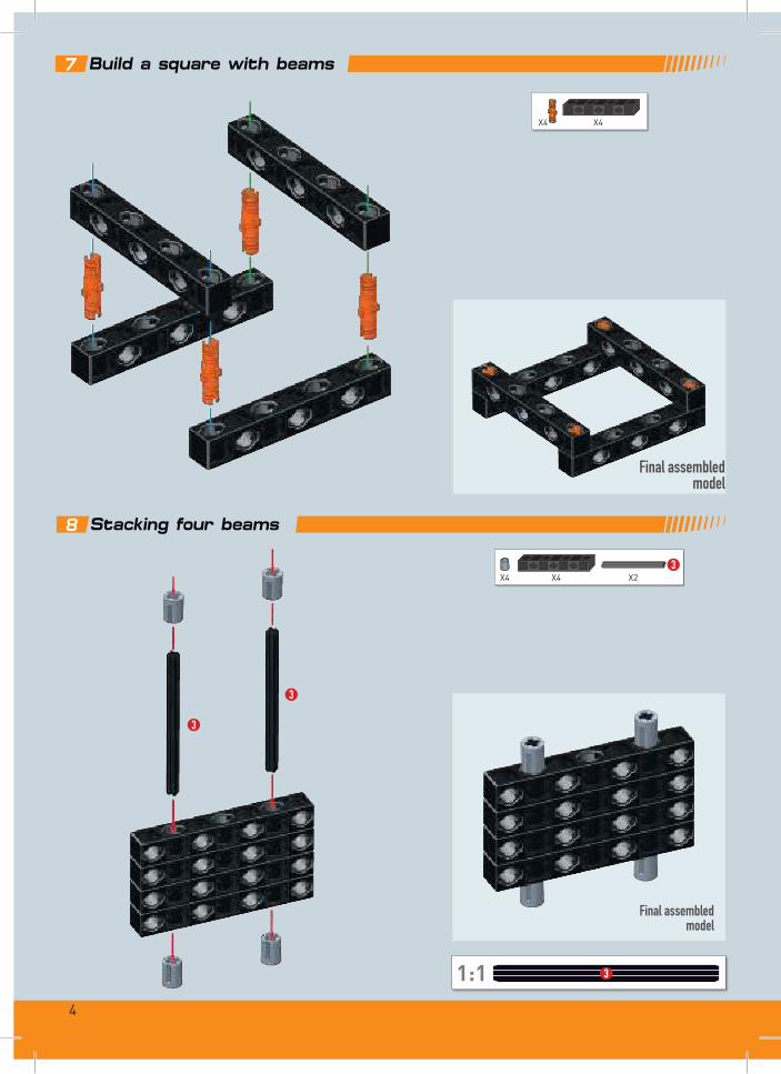
Final assembled model
Final assembled model
7 Build a square with beams
8 Stacking four beams
X4 X4 X23
3
3
1:1 3
9
X4 X4
5
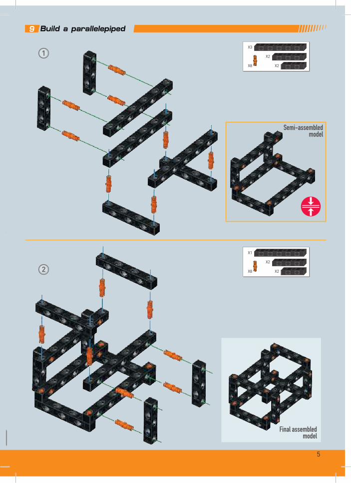
Semi-assembled model
Final assembled model
9 Build a parallelepiped
1
2
X8 X2
X3
X2
X8 X2
X1
X2
6
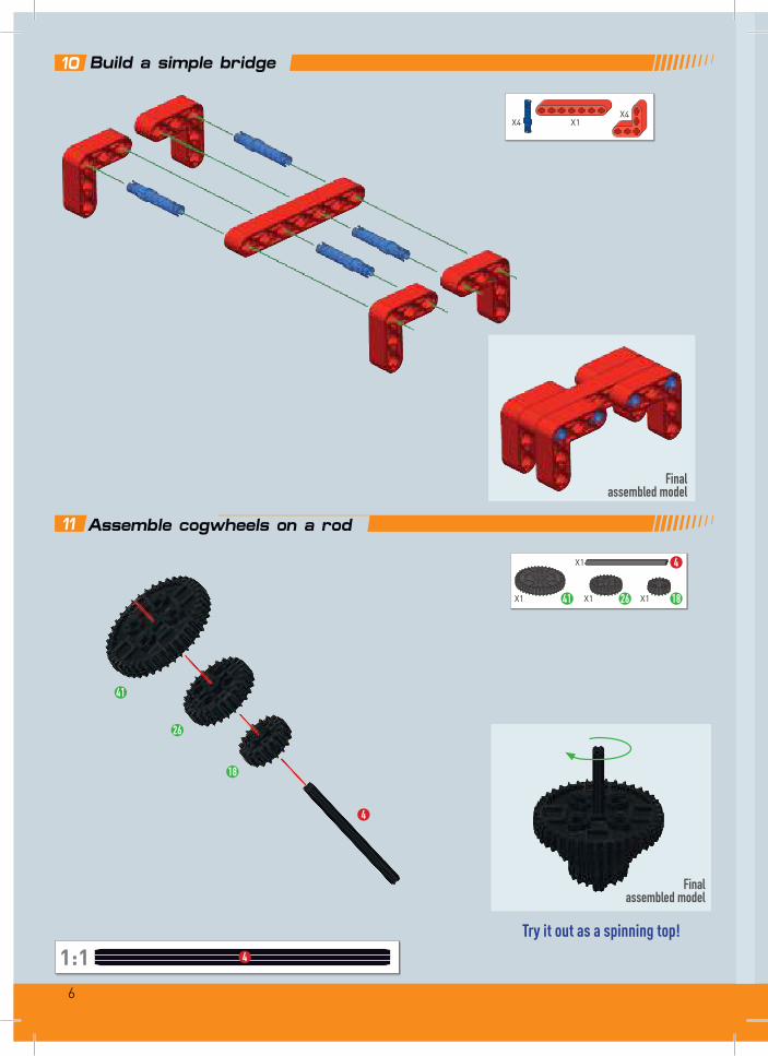
Final assembled model
Final assembled model
10 Build a simple bridge
11 Assemble cogwheels on a rod
Try it out as a spinning top!1:1
X1 26X1 41 X1 18
X1 4
26
41
18
4
4
X4 X1X4

7
SIMPLE MACHINES
A simple machine is an instrument that allows for balancing and overcoming RESISTANCE (weight, resistance force = R) with EFFORT (manpower = E).
• Pairs of levers also obey this principle.
• Levers are classified by the relative positions of the EFFORT, RESISTANCE and FULCRUM.
FULCRUM EFFORTRESISTANCE
A lever is a simple machine that is made up of a rigid bar which can rotate around a fixed point called the fulcrum.
LEVERS
Since ancient times humans have made use of many of these mech-anisms to increase their strength and enable them to accomplish great feats which can still be admired today. Wheelbarrow Pincers
Nutcracker
See-saw
Balance Pulley

8
12Build
a C
lass
1 lev
er: pince
rs
1
3
1:1
3
X4
X1
X8 X23
X2

9
Final
asse
mbled
mod
el1:1
1:1
The
FULC
RUM
lies
betw
een
the
RESI
STAN
CE an
d the
EFFO
RT.
2
1 3
31
X4
X13
X2
X2X2
X11
10
Final
asse
mbled
mod
el
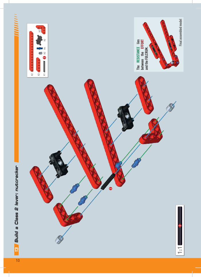
13Build
a C
lass
2 lev
er: nutc
rack
er
1:1
2
2
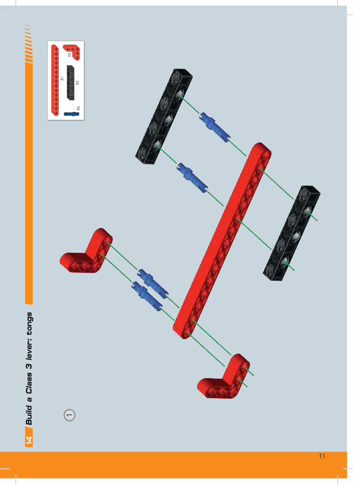
14Build
a C
lass
3 lev
er: to
ngs
The
RESI
STAN
CE
lies
betw
een
the
EFFO
RT
and t
he FU
LCRU
M.
X2
X2X4
X2 X2 X12
X2
11
14Build
a C
lass
3 lev
er: to
ngs
1X2
X1
X2X4

12
2
The
EFFO
RT
lies
betw
een
the
RE-
SIST
ANCE
and
the
FULC
RUM.
1:1
33
Final
asse
mbled
mod
el
X2
X4X3
X2
X13
X1
X1 X2
13
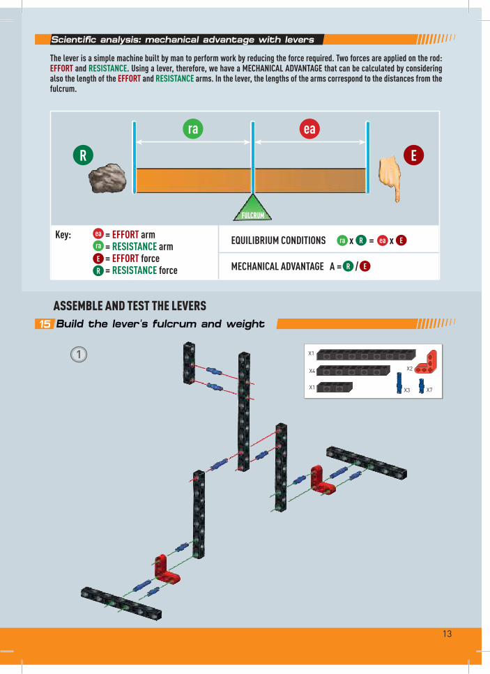
Scientific analysis: mechanical advantage with levers
The lever is a simple machine built by man to perform work by reducing the force required. Two forces are applied on the rod: EFFORT and RESISTANCE. Using a lever, therefore, we have a MECHANICAL ADVANTAGE that can be calculated by considering also the length of the EFFORT and RESISTANCE arms. In the lever, the lengths of the arms correspond to the distances from the fulcrum.
ASSEMBLE AND TEST THE LEVERS15 Build the lever's fulcrum and weight
Key: = EFFORT arm = RESISTANCE arm = EFFORT force = RESISTANCE force
EQUILIBRIUM CONDITIONS x = x
MECHANICAL ADVANTAGE A = /
ra
R
ea
E
ra
R
ea
E
ra R ea E
R E
FULCRUM
1 X1
X3
X2X4
X1 X7

14
In Activities 16-17-18 try moving the fulcrum and then applying downward pressure to the EFFORT arm with your hand to see the differences between the levers.
ASSEMBLING THE WEIGHT
2
Assembled weight
3
3
X2
X1 3 X2 X4
X1
X2 X2
X1 3 X2
X2
X2

15
16 Assemble and test a mechanically advantaged lever
Find the equilibrium of this type of mechanical device: position the weight (RESISTANCE) on one side of the lever and gently press down with your hand (EFFORT) on the other side.
Note the position of the fulcrum!• The EFFORT arm is longer.• The EFFORT is less than the RESISTANCE.
RESISTANCE
EFFORT
FULCRUM
TRY IT OUT!
Final assembled model
Note: slide a collar onto the rod at the fulcrum to secure the lever, as shown.
X1

16
17 Assemble and test a mechanically neutral lever
Find the equilibrium of this type of mechanical device: position the weight (RESISTANCE) on one side of the lever and gently press down with your hand (EFFORT) on the other side.
Note the position of the fulcrum!• The arms are the same.• The EFFORT is equal to the RESISTANCE.
RESISTANCE
EFFORT
FULCRUM
TRY IT OUT!
Final assembled model
Note: slide a collar onto the rod at the fulcrum to secure the lever, as shown.
X1
17
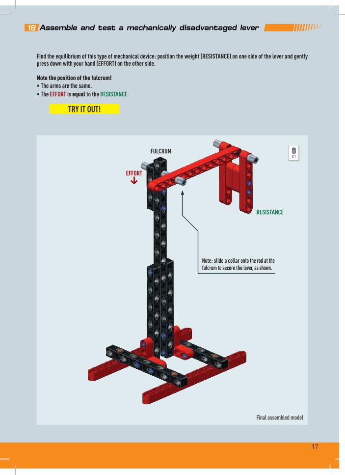
18 Assemble and test a mechanically disadvantaged lever
Find the equilibrium of this type of mechanical device: position the weight (RESISTANCE) on one side of the lever and gently press down with your hand (EFFORT) on the other side.
Note the position of the fulcrum!• The arms are the same.• The EFFORT is equal to the RESISTANCE.
RESISTANCE
EFFORT
FULCRUM
TRY IT OUT!
Final assembled model
Note: slide a collar onto the rod at the fulcrum to secure the lever, as shown.
X1

18
19Ass
emble a
balance
20
Build
and t
est
a s
ee-s
aw
TRY I
T OUT
!Fin
al as
semb
led m
odel
The b
alanc
e is a
clas
s 1 le
ver
3
3
3
1:1
3
X2
X4
X2
X6X1 X2 X1
X33
X3

19
20
Build
and t
est
a s
ee-s
aw
1:1
3
3
1:1
2
2
2
1X4
X2 X2 X2X2
X13
X6
X2
X22

20
Final assembled model
The see-saw is a class 1 lever
In the third century BC, Archimedes was a great scientist and experimenter with levers.
Note: the lever of the see-saw must rotate freely around the fulcrum.
Try it yourself: find the equilibrium of the see-saw by varying the weight and distances from the fulcrum of the Resistance and Effort forces.
TRY IT OUT!
2 X2X4

21
COGWHEELS
Cogwheels transmit motion between suitably positioned axles (rods) via teeth.• In a pair of cogwheels, if one cogwheel turns in one direction the other turns in the opposite direction. One of the two wheels
transmits motion (drive wheel) while the other receives it (driven wheel).• To maintain the same direction of rotation a third cogwheel must be inserted between the two.• With two different cogwheels, the smaller one – having only a few teeth – is called the pinion, while the one with many
teeth is called the crown wheel. Multiple cogwheels make up a gear train.
1
Assembled stand
21 Assemble the test stand for reverse rotation
X2
X2
X4
X2
X12

22
2
4
1:1 4
3
1:1 3Final assembled model
Anti-clockwise
Clockwise
18
18
22
X1
X2
X1X1
X1 X1
43
X2 18
23
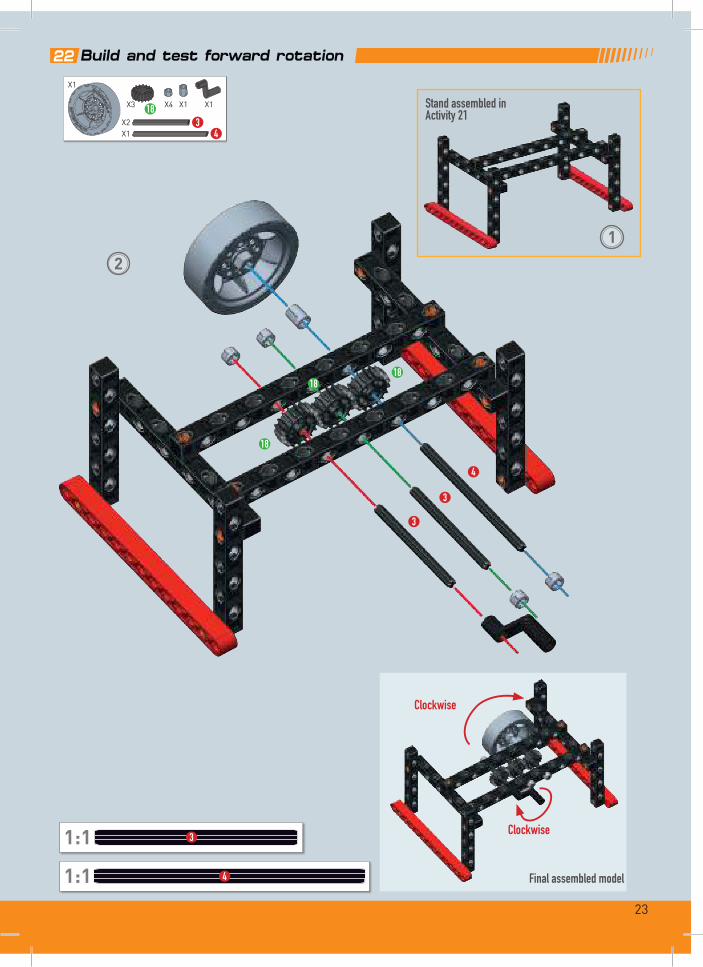
22 Build and test forward rotation
1:1 4
4
1:1 3
3
3
18
1818
2
Final assembled model
Clockwise
Clockwise
1
Stand assembled in Activity 21
X1
X4
X2X1
X1 X1
43
X3 18

24
23 Assemble and test alternating movement
Final assembled model
4
1:1 4
4
2
1:1 2
2
26
41
1
Stand assembled in Activity 21
180°
2X1
X1 X5X4
X1
X1
X2 4X2 2
X1 26
41
X1
25
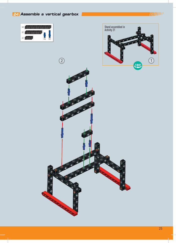
1
Stand assembled in Activity 21
180°
24 Assemble a vertical gearbox
2
X2X4
X2
X1
X1

26
3
Final assembled model
4
2
41
10
180°
1:1 41:1 2
2X1
X1 4
X1 2
X1 10
41
X1
X1
X2

27
GEAR RATIO
25 Build a horizontal to vertical gearbox
2
2
1:1 2
Final assembled model
26
Carefully observe the cogwheels when they rotate and compare the number of revolutions completed by the various cogwheels. When the larger cogwheel has completed a revolution, the small-er one will have completed 4. You can prove this by dividing the number of teeth of the two cogwheels (ratio).
Example: how to calculate the gear ratio.
41 teeth (larger wheel)10 teeth (smaller wheel)
= 4.1 revolutions
1
Stand assembled in Activity 212
X1
X1 2
26
X2

28
Assembled stand
PRE-ACTIVITY TASKAssemble a test stand for the gearbox elements
X12
X2
X2
X4
X2

29
Final assembled model
26 The worm screw for lifting
1:1 3
Technical and scientific analysisTechnically called an involute, the worm screw is a cylindrical helical gear.In a worm-and-gear set, the former is called the ‘driver’, because motion can only be transferred from the worm screw to the gear and not vice-versa. The worm screw can therefore be used to lock the mating gear in a certain position.
3
18
10
2
2
2
1:1 2
Assembled stand
Stand assembled in the pre-activity task
X3 23X1X6
X2X1
X1X1 10 X1 18

30
1:1 5
27 The worm screw as a reduction gear
Gear ratioThe worm screw makes it possible to achieve high reductions.Turn the wheel and see how the gear rotates slowly.
Check the assembly!
5
5
3
10
41
Final assembled model
1:1 2
Stand assembled in the pre-activity task
3X1
X1
X1 10
X1 5X2
X1
X4
X2
X1 41
X1 X1

31
Final assembled model
TRY IT OUT!
4
28 Using the transmission module for counter-rotation
Insert the module between the beams, by partially disassembling the stand. Then arrange the gears as shown in the picture.
3
3
18
12
12
12
3 3
4
X2
X6
X1 4
X1
X1 18
X3 12
X2
3X2
1:1 31:1 4
Stand assembled in the pre-activity task
X1
32
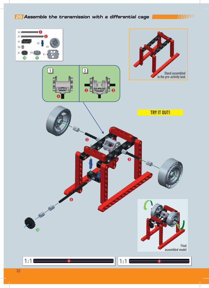
TRY IT OUT!
29 Assemble the transmission with a differential cage
3
3 3
3
4
21
4
18
X1X2
X6
X3X1 X1
18 12
3X2
X1 4
X2
Stand assembled in the pre-activity task
1:1 31:1 4
Final assembled model
30
An a
ncien
t w
ar
mach
ine: t
he
batt
ering-r
am

33
30
An a
ncien
t w
ar
mach
ine: t
he
batt
ering-r
am
1 Front
X2X2
X2X4

34
2
3
3
3
5
21
1
1:1
5
1:1
31:1
21:1
1
X1
X2 X1 X3 X1X1X2
X2
5
12
3
X1
2641
41
26
X3X2

35
3
X1
X4
X1X2
X6

36
4
4
Final assembled model
Front
1:1 4
X1
X1X2
X1
X1 4
X3X2 X5X1