Mechanically compensated type for midwave infrared zoom system ...
7
Mechanically compensated type for midwave infrared zoom system with a large zoom ratio Zhou Hao Liu Ying Sun Qiang Li Chun Zhang Xiaolong Huang Jianbo Downloaded From: https://www.spiedigitallibrary.org/journals/Optical-Engineering on 4/5/2018 Terms of Use: https://www.spiedigitallibrary.org/terms-of-use
Transcript of Mechanically compensated type for midwave infrared zoom system ...

Mechanically compensated type formidwave infrared zoom system with alarge zoom ratio
Zhou HaoLiu YingSun QiangLi ChunZhang XiaolongHuang Jianbo
Downloaded From: https://www.spiedigitallibrary.org/journals/Optical-Engineering on 4/5/2018 Terms of Use: https://www.spiedigitallibrary.org/terms-of-use

Mechanically compensated type for midwave infraredzoom system with a large zoom ratio
Zhou HaoChinese Academy of SciencesChangchun Institute of OpticsFine Mechanics, and PhysicsChangchun 130033, Chinaand
Graduate School of the Chinese Academy ofSciences
Beijing 100049, ChinaE-mail: [email protected]
Liu YingSun QiangLi ChunChinese Academy of SciencesChangchun Institute of OpticsFine Mechanics, and PhysicsChangchun 130033, China
Zhang XiaolongChinese Academy of SciencesChangchun Institute of OpticsFine Mechanics, and PhysicsChangchun 130033, Chinaand
Graduate School of the Chinese Academy ofSciences
Beijing 100049, China
Huang JianboChinese Academy of SciencesChangchun Institute of OpticsFine Mechanics, and PhysicsChangchun 130033, China
Abstract. In some circumstances, there is a need for a midwave infrared(MWIR) zoom system with a large zoom ratio. Using traditional four-component mechanically compensated types of MWIR zoom systemscannot achieve a large zoom ratio. To meet this demand, we describe asix-component mechanically compensated type. The thin-lens theory ofthis type is developed and equations are presented. Using the six-compo-nent mechanically compensated type, a MWIR continuous zoom systemwith a zoom ratio of 45 is designed, and it has high image quality over theentire zoom range. © The Authors. Published by SPIE under a Creative CommonsAttribution 3.0 Unported License. Distribution or reproduction of this work in whole or in partrequires full attribution of the original publication, including its DOI. [DOI: 10.1117/1.OE.52.1.013002]
Subject terms: midwave infrared; continuous zoom; large zoom ratio; optical design.
Paper 121531 received Oct. 22, 2012; revised manuscript received Nov. 23, 2012;accepted for publication Dec. 4, 2012; published online Jan. 7, 2013.
1 IntroductionInfrared systems operating in midwave infrared (MWIR,from 3 to 5 μm) are used in civilian and military applications,such as law enforcement, life rescue, territorial surveillance,vehicle tracking, aerial surveillance, and stealth searching.1–3
In recent years, the demand for MWIR zoom systems hasincreased. In these systems, the wide field of view (WFOV)is used for observing a large scene area for possible targets ofinterest, and the narrow field of view (NFOV) is used forclose-up identification of the target of interest.3–12 In somecircumstances, such as aerial surveillance and life rescue,there is a need for wider observation of the scene.3 Thereis a significant need to design a MWIR zoom system witha large zoom ratio.
There are two types of zoom systems: optically compen-sated and mechanically compensated. Almost all infraredzoom systems are mechanically compensated.13 In a tradi-tional mechanically compensated zoom system, the secondcomponent moves for changes in focal length, while thethird component moves to eliminate image shift; the image
stays in focus throughout the zoom range (refer to Fig. 1).13
Using a traditional four-component mechanically compen-sated type, MWIR zoom systems cannot achieve a largezoom ratio (such as 45) with a general F/number (suchas 4).1,2,14–21 In this paper, we examine the six-componentmechanically compensated type, which can achieve a largezoom ratio. The design concept is shown in Fig. 2; the secondand fourth components are linked and move together forchanges in focal length, while the third and fifth componentsare linked and move together to eliminate image shift. Thistype still involves just two moving groups. It is likely thatthe zoom range could also be achieved with a third movinggroup, but there is additional expense and complexity to doso. Section 2 presents the thin-lens theory. In Sec. 3, a MWIRcontinuous zoom system with a zoom ratio of 45 is designed.Finally, in Sec. 4, we present our conclusions.
2 Thin-Lens TheoryFigure 3 represents a general six-component zoom system,with the zoom components in their long-zoom positions.
Optical Engineering 013002-1 January 2013/Vol. 52(1)
Optical Engineering 52(1), 013002 (January 2013)
Downloaded From: https://www.spiedigitallibrary.org/journals/Optical-Engineering on 4/5/2018 Terms of Use: https://www.spiedigitallibrary.org/terms-of-use
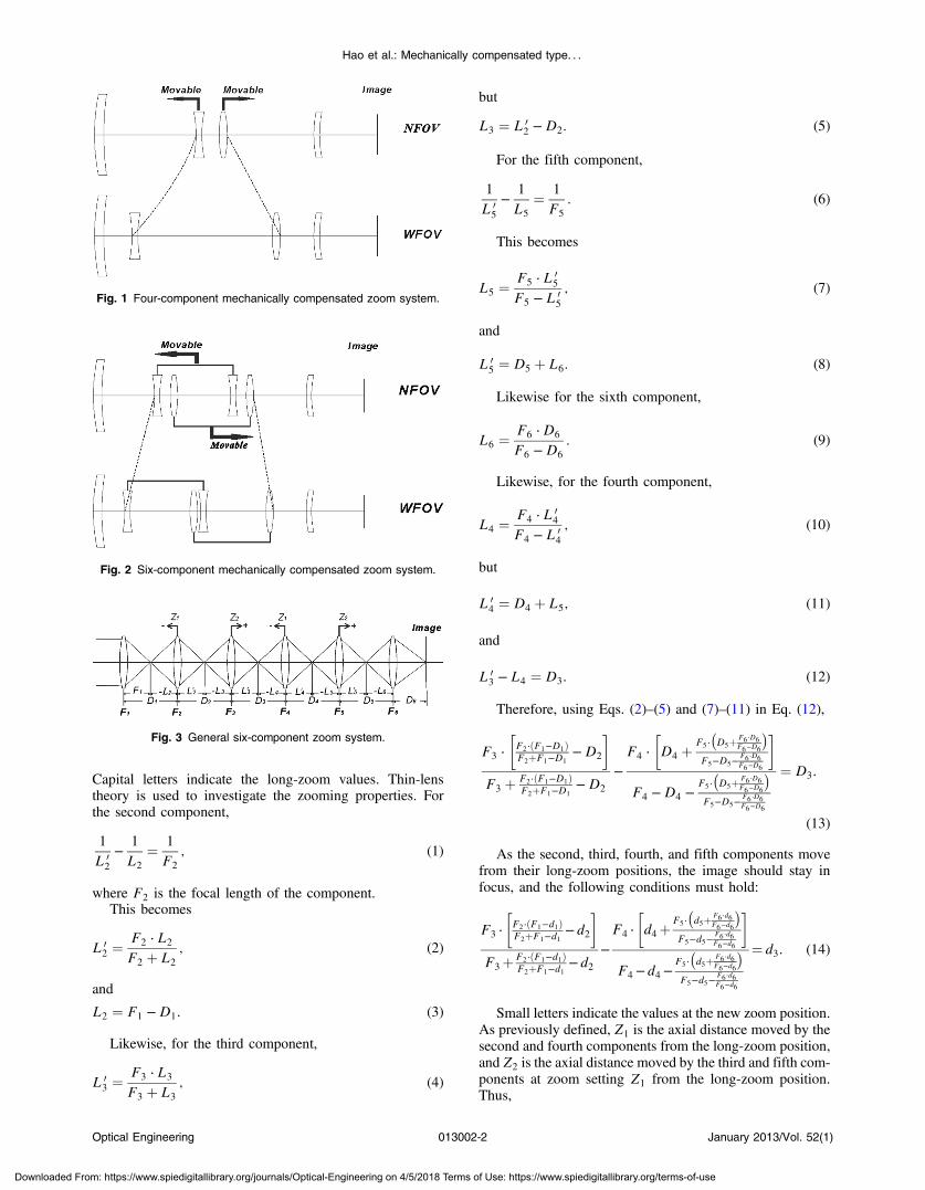
Capital letters indicate the long-zoom values. Thin-lenstheory is used to investigate the zooming properties. Forthe second component,
1
L 02
−1
L2
¼ 1
F2
; (1)
where F2 is the focal length of the component.This becomes
L 02 ¼
F2 ⋅ L2
F2 þ L2
; (2)
and
L2 ¼ F1 −D1: (3)
Likewise, for the third component,
L 03 ¼
F3 ⋅ L3
F3 þ L3
; (4)
but
L3 ¼ L 02 −D2: (5)
For the fifth component,
1
L 05
−1
L5
¼ 1
F5
: (6)
This becomes
L5 ¼F5 ⋅ L 0
5
F5 − L 05
; (7)
and
L 05 ¼ D5 þ L6: (8)
Likewise for the sixth component,
L6 ¼F6 ⋅D6
F6 −D6
: (9)
Likewise, for the fourth component,
L4 ¼F4 ⋅ L 0
4
F4 − L 04
; (10)
but
L 04 ¼ D4 þ L5; (11)
and
L 03 − L4 ¼ D3: (12)
Therefore, using Eqs. (2)–(5) and (7)–(11) in Eq. (12),
F3 ⋅�F2⋅ðF1−D1ÞF2þF1−D1
−D2
�
F3 þ F2⋅ðF1−D1ÞF2þF1−D1
−D2
−F4 ⋅
�D4 þ
F5⋅�D5þ F6 ⋅D6
F6−D6
�F5−D5−
F6 ⋅D6F6−D6
�
F4 −D4 −F5⋅�D5þ F6 ⋅D6
F6−D6
�F5−D5−
F6 ⋅D6F6−D6
¼ D3:
(13)
As the second, third, fourth, and fifth components movefrom their long-zoom positions, the image should stay infocus, and the following conditions must hold:
F3 ⋅�F2⋅ðF1−d1ÞF2þF1−d1
−d2
�
F3þ F2⋅ðF1−d1ÞF2þF1−d1
−d2−F4 ⋅
�d4þ
F5⋅�d5þ F6 ⋅d6
F6−d6
�F5−d5−
F6 ⋅d6F6−d6
�
F4−d4−F5⋅�d5þ F6 ⋅d6
F6−d6
�F5−d5−
F6 ⋅d6F6−d6
¼ d3: (14)
Small letters indicate the values at the new zoom position.As previously defined, Z1 is the axial distance moved by thesecond and fourth components from the long-zoom position,and Z2 is the axial distance moved by the third and fifth com-ponents at zoom setting Z1 from the long-zoom position.Thus,
Fig. 1 Four-component mechanically compensated zoom system.
Fig. 2 Six-component mechanically compensated zoom system.
Fig. 3 General six-component zoom system.
Optical Engineering 013002-2 January 2013/Vol. 52(1)
Hao et al.: Mechanically compensated type. . .
Downloaded From: https://www.spiedigitallibrary.org/journals/Optical-Engineering on 4/5/2018 Terms of Use: https://www.spiedigitallibrary.org/terms-of-use

d1 ¼ D1 þ Z1: (15)
d2 ¼ D2 þ Z2 − Z1: (16)
d3 ¼ D3 − Z2 þ Z1: (17)
d4 ¼ D4 þ Z2 − Z1: (18)
d5 ¼ D5 − Z2: (19)
d6 ¼ D6: (20)
And by combining Eqs. (14)–(20),
Z2 þa1 ⋅ Z2
2 þ b1 ⋅ Z2 þ c1Z22 − b2 ⋅ Z2 − c2
þ b3 ⋅ Z2 − 2
Z2 − c4− c5 ¼ 0; (21)
where
a1 ¼ F4
b1 ¼ F4 ⋅�D4 −D5 −
F6 ⋅D6
F6 −D6
− Z1
�;
b2 ¼ F4 −D4 þ Z1 þD5 þF6 ⋅D6
F6 −D6
b3 ¼ F3
c1 ¼ F4 ⋅�F5 −D5 −
F6 ⋅D6
F6 −D6
�⋅ ðD4 − Z1Þ
þ F4 ⋅ F5 ⋅�D5 þ
F6 ⋅D6
F6 −D6
�
c2 ¼�F5 −D5 −
F6 ⋅D6
F6 −D6
�⋅ ðF4 −D4 þ Z1Þ
− F5 ⋅�D5 þ
F6 ⋅D6
F6 −D6
�
c3 ¼ F3 ⋅�F2 ⋅ ðF1 −D1 − Z1ÞF2 þ F1 −D1 − Z1
−D2 þ Z1
�
c4 ¼ F3 þF2 ⋅ ðF1 −D1 − Z1ÞF2 þ F1 −D1 − Z1
−D2 þ Z1
c5 ¼ D3 þ Z1
At the zoom setting Z1, as the long-zoom values areknown, the above values of a1, b1, b2, b3, c1, c2, c3, c4and c5 can then be evaluated. After rearrangement,Eq. (21) becomes
Z42 þ k3 ⋅ Z3
2 þ k2 ⋅ Z22 þ k1 ⋅ Z2 þ k0 ¼ 0; (22)
where
k3 ¼ a1 − b2 þ b3 − c4 − c5
k2 ¼ b1 − c2 − c3 − a1 ⋅ c4 − b2 ⋅ b3 þ b2 ⋅ c4 þ b2 ⋅ c5þ c4 ⋅ c5
k1 ¼ c1 − b1 ⋅ c4 þ b2 ⋅ c3 − c2 ⋅ b3 þ c2 ⋅ c4 þ c2 ⋅ c5− b2 ⋅ c4 ⋅ c5
k0 ¼ −c1 ⋅ c4 þ c2 ⋅ c3 − c2 ⋅ c4 ⋅ c5
Using Eq. (22), the motion of the third and fifth compo-nents Z2 at the the zoom setting Z1 may be evaluated. UsingEqs. (14)–(19), the distance values may be found. Then, the
Table 1 Characteristics of the system.
Zoom range 45
Focal length range −10 to −450 mm
F∕number 4
Image plane diagonal 12 mm
Spectral band 3.7 to 4.8 μm
Table 2 The initial data of the thin-lens zoom system.
F 1 135.646 D1 79.188
F 2 −36.930 D2 9.528
F 3 71.126 D3 105.237
F 4 −38.214 D4 15.312
F 5 50.702 D5 172.529
F 6 27.052 D6 51.512
NOTE: Unit: mm.
Optical Engineering 013002-3 January 2013/Vol. 52(1)
Hao et al.: Mechanically compensated type. . .
Downloaded From: https://www.spiedigitallibrary.org/journals/Optical-Engineering on 4/5/2018 Terms of Use: https://www.spiedigitallibrary.org/terms-of-use
corresponding effective focal length (EFL) of the system isobtained.
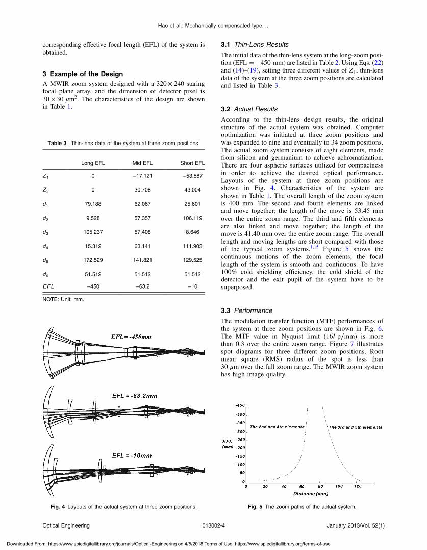
3 Example of the DesignA MWIR zoom system designed with a 320 × 240 staringfocal plane array, and the dimension of detector pixel is30 × 30 μm2. The characteristics of the design are shownin Table 1.
3.1 Thin-Lens Results
The initial data of the thin-lens system at the long-zoom posi-tion (EFL ¼ −450 mm) are listed in Table 2. Using Eqs. (22)and (14)–(19), setting three different values of Z1, thin-lensdata of the system at the three zoom positions are calculatedand listed in Table 3.
3.2 Actual Results
According to the thin-lens design results, the originalstructure of the actual system was obtained. Computeroptimization was initiated at three zoom positions andwas expanded to nine and eventually to 34 zoom positions.The actual zoom system consists of eight elements, madefrom silicon and germanium to achieve achromatization.There are four aspheric surfaces utilized for compactnessin order to achieve the desired optical performance.Layouts of the system at three zoom positions areshown in Fig. 4. Characteristics of the system areshown in Table 1. The overall length of the zoom systemis 400 mm. The second and fourth elements are linkedand move together; the length of the move is 53.45 mmover the entire zoom range. The third and fifth elementsare also linked and move together; the length of themove is 41.40 mm over the entire zoom range. The overalllength and moving lengths are short compared with thoseof the typical zoom systems.1,15 Figure 5 shows thecontinuous motions of the zoom elements; the focallength of the system is smooth and continuous. To have100% cold shielding efficiency, the cold shield of thedetector and the exit pupil of the system have to besuperposed.
3.3 Performance
The modulation transfer function (MTF) performances ofthe system at three zoom positions are shown in Fig. 6.The MTF value in Nyquist limit (16l p∕mm) is morethan 0.3 over the entire zoom range. Figure 7 illustratesspot diagrams for three different zoom positions. Rootmean square (RMS) radius of the spot is less than30 μm over the full zoom range. The MWIR zoom systemhas high image quality.
Fig. 5 The zoom paths of the actual system.Fig. 4 Layouts of the actual system at three zoom positions.
Table 3 Thin-lens data of the system at three zoom positions.
Long EFL Mid EFL Short EFL
Z 1 0 −17.121 −53.587
Z 2 0 30.708 43.004
d1 79.188 62.067 25.601
d2 9.528 57.357 106.119
d3 105.237 57.408 8.646
d4 15.312 63.141 111.903
d5 172.529 141.821 129.525
d6 51.512 51.512 51.512
EFL −450 −63.2 −10
NOTE: Unit: mm.
Optical Engineering 013002-4 January 2013/Vol. 52(1)
Hao et al.: Mechanically compensated type. . .
Downloaded From: https://www.spiedigitallibrary.org/journals/Optical-Engineering on 4/5/2018 Terms of Use: https://www.spiedigitallibrary.org/terms-of-use

Fig. 7 Spot diagrams of the system at three zoom positions.
Fig. 6 MTF curves of the system at three zoom positions.
Optical Engineering 013002-5 January 2013/Vol. 52(1)
Hao et al.: Mechanically compensated type. . .
Downloaded From: https://www.spiedigitallibrary.org/journals/Optical-Engineering on 4/5/2018 Terms of Use: https://www.spiedigitallibrary.org/terms-of-use

4 ConclusionsUsing six-component mechanically compensated type, aMWIR zoom system is designed in this paper. The resultspresent this zoom lens achieving good image quality, withspecifications of 45 zoom ratio and F∕4, by utilizing the lay-out of interlaced mechanical linkage to perform the role ofvariator and compensator. The six-component mechanicallycompensated type system can achieve a large zoom ratio withshort overall length and moving lengths. The continuousmotions of the zoom elements are smooth. Image qualitiesare good over the entire zoom range. The six-componentmechanically compensated type has advantages in the designof MWIR zoom system with a large zoom ratio.
References
1. R. L. Sinclair, “High magnification zoom lenses for 3–5 μm applica-tions,” Proc. SPIE 3429, 11–18 (1998).
2. C. W. Kuo, J. M. Miao, and C. H. Tai, “Midwave infrared optical zoom-ing design and kinoform degrading evaluation methods,” Appl. Opt.50(18), 3043–3049 (2011).
3. M. N. Akram, “Design of a multiple-field-of-view optical system for3- to 5-μm infrared focal-plane arrays,” Opt. Eng. 42(6), 1704–1714(2003).
4. H. S. Kim, C. W. Kim, and S. M. Hong, “Compact mid-wavelengthinfrared zoom camera with 20∶1 zoom range and automatic athermal-ization,” Opt. Eng. 41(7), 1661–1667 (2002).
5. H. S. Kim et al., “Compact MWIR camera with ×20 zoom optics,” Proc.SPIE 4369, 673–679 (2001).
6. M. W. Chang, “Design of a compact zoom system for 3–5 micron waveband thermal imager,” Proc. SPIE 3129, 144–155 (1997).
7. Z. Y. Fan et al., “Design of high ratio middle infrared continuous zoomoptical system,” Proc. SPIE 8193, 81931R (2011).
8. M. N. Akram andM. H. Asghar, “Step-zoom dual-field-of-view infraredtelescope,” Appl. Opt. 42(13), 2312–2316 (2003).
9. Z. D. Xu, X. Liu, and Z. Wei, “Airborne IR system design using 640 ×512 element detector,” J. Nanjing Univ. Aeronaut. Astronaut. 39(4),524–529 (2007).
10. J. Q. Meng, “Dual field zoom (×6) infrared imaging optical system,”Infrared Laser Eng. 37(1), 89–92 (2008).
11. L. Zhang, “Optical design for middle infrared zoom system,” J. Appl.Opt. 27(1), 32–34 (2006).
12. H. Y. Gao and T. Xiong, “Mid-wavelength infrared dual field-of-viewoptical system,” Opt. Precision Eng. 16(10), 1891–1894 (2008).
13. A. Mann, Infrared Optics and Zoom Lenses, SPIE Press, Bellingham,WA (2009).
14. R. G. Li et al., “Design of dual-field-of-view optical system for mid-wave infrared focal-plane arrays,” Laser Infrared 39(6), 640–642 (2009).
15. L. J. Chen, P. Li, and L. Ma, “Compact MWIR zoom system,” InfraredTechnol. 32(10), 562–566 (2010).
16. H. T. Wang and L. X. Guo, “Cooled thermal imaging mid-wavelengthinfrared zoom camera,” Infrared Technol. 29(1), 8–11 (2007).
17. M. C. Sanson and J. Cornell, “MWIR continuous zoom with large zoomrange,” Proc. SPIE 7660, 76601X (2010).
18. M. C. Sanson et al., “Development of MWIR continuous zoom withlarge zoom range,” Proc. SPIE 8012, 80122F (2011).
19. Y. Aron et al., “Topaz: a novel design of a high magnification,athermalized 1∶30 zoom in the MWIR,” Proc. SPIE 5406, 97–106(2004).
20. H. Y. Gao, T. Xiong, and C. C. Yang, “Middle infrared continuouszoom optical system,” Opt. Precision Eng. 15(7), 1038–1043 (2007).
21. A. Porta et al., “ERICA: compact MWIR camera with 20× stepzoom optics and advanced processing,” Proc. SPIE 6737, 673706(2007).
Zhou Hao received a BS degree in opticalinformation science and technology fromHefei University of Technology in 2009. Heis currently pursuing his PhD at theGraduate School of the Chinese Academyof Sciences. His research interests are infra-red optical systems and system evaluation.
Liu Ying received a PhD degree in opticalengineering from Graduate School of theChinese Academy of Sciences in 2010.She is currently a research assistant at theChangchun Institute of Optics, FineMechanics, and Physics, Chinese Academyof Sciences. Her research interests areinfrared optical systems and spectrometer.
Sun Qiang received a PhD degree in opticalengineering from Nankai University in 2003.He is currently a professor at the ChangchunInstitute of Optics, Fine Mechanics, andPhysics, Chinese Academy of Sciences. Hisresearch interests are infrared optical sys-tems and spectrometer.
Li Chun received an MS degree in opticalengineering from Graduate School of theChinese Academy of Sciences in 2010.He is currently a research assistant atthe Changchun Institute of Optics, FineMechanics, and Physics, Chinese Academyof Sciences. His research interests are imageenhancement and image fusion.
Zhang Xiaolong received a BS degree inapplied physics from Qingdao University ofScience and Technology in 2009. He iscurrently pursuing his PhD at the GraduateSchool of the Chinese Academy of Sciences.His research interests are optics design andtesting.
Huang Jianbo received an MS degree inmechanical engineering from Jilin Universityin 2008. He is currently a research assistantat the Changchun Institute of Optics, FineMechanics, and Physics, Chinese Academyof Sciences. His research interests aremechanical system design and testing.
Optical Engineering 013002-6 January 2013/Vol. 52(1)
Hao et al.: Mechanically compensated type. . .
Downloaded From: https://www.spiedigitallibrary.org/journals/Optical-Engineering on 4/5/2018 Terms of Use: https://www.spiedigitallibrary.org/terms-of-use