Mechanical Windows Service Manual-KWF rotary wrac-12K...
23
Service manual 1 Service Manual AIR CONDITIONER Window Type - Mechanical Control MODEL 51KWF012733 51KWF018733 51KWF024733 51KWF012733A 51KWF018733A 51KWF024733A
Transcript of Mechanical Windows Service Manual-KWF rotary wrac-12K...
Service manual
1
Service Manual AIR CONDITIONER
Window Type - Mechanical Control
MODEL
51KWF012733
51KWF018733
51KWF024733
51KWF012733A
51KWF018733A
51KWF024733A
Service manual
2
CONTENT 1. Precaution. ................................................................................................................................3
1.1 Safety precaution.................................................................................................................3
1.2 Warning...............................................................................................................................3
1.3 Caution. ...............................................................................................................................3
2. Features and panel.....................................................................................................................4
2.1 Features. ..............................................................................................................................4
2.2 Control panel illustration.....................................................................................................4
3. Unit dimension..........................................................................................................................8
4. Installation.................................................................................................................................9
4.1 Select the best location........................................................................................................9
4.2 Check off installation. .......................................................................................................10
4.3 How to drain......................................................................................................................10
4.4 How to install. ...................................................................................................................11
5. Refrigerant cycle diagram. ......................................................................................................14
6. Operation limits.......................................................................................................................15
6.1 Cooling operation..............................................................................................................15
7. Schematic and wiring diagram................................................................................................16
7.1 51KWF012733..................................................................................................................16
7.2 51KWF018733..................................................................................................................16
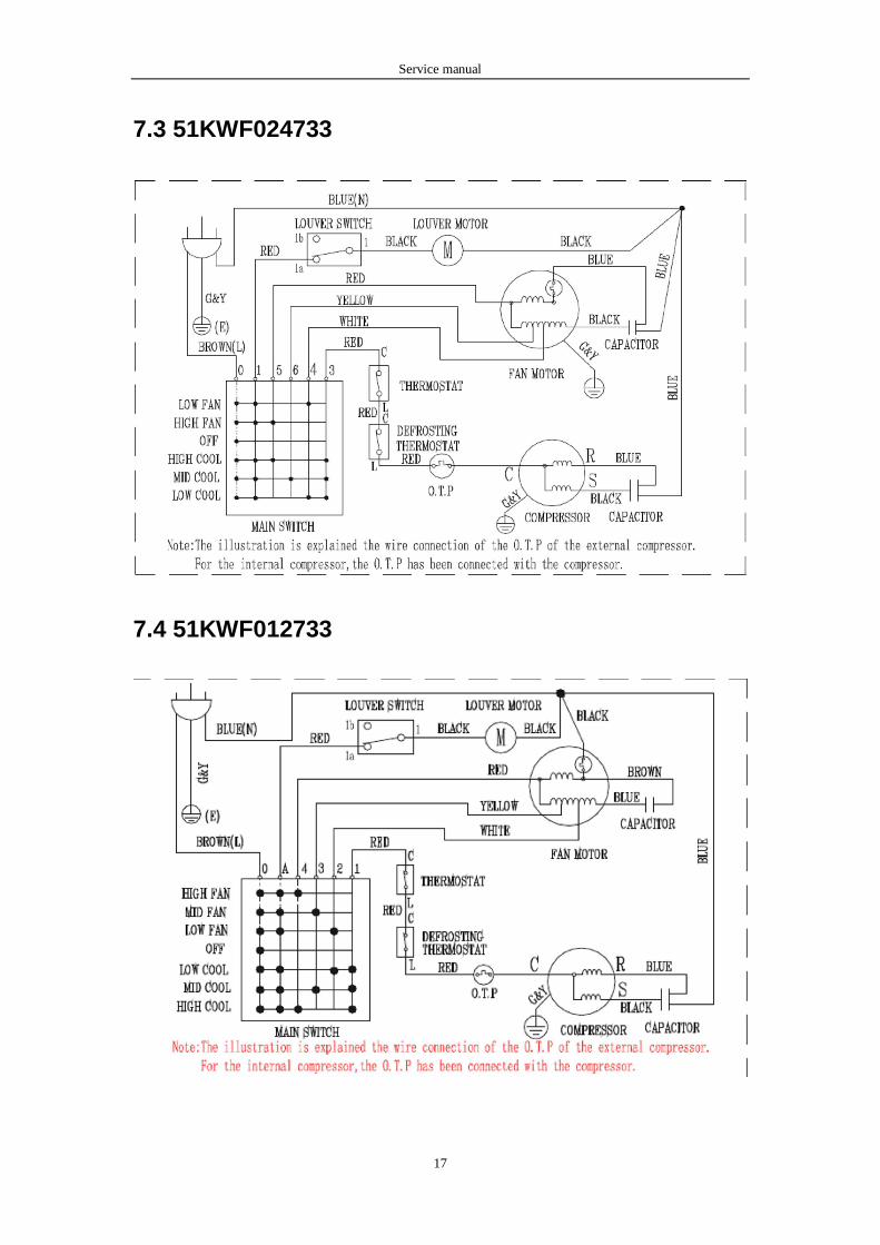
7.3 51KWF024733..................................................................................................................17
7.4 51KWF012733A...............................................................................................................17
7.5 51KWF018733A...............................................................................................................18
7.6 51KWF024733A...............................................................................................................18
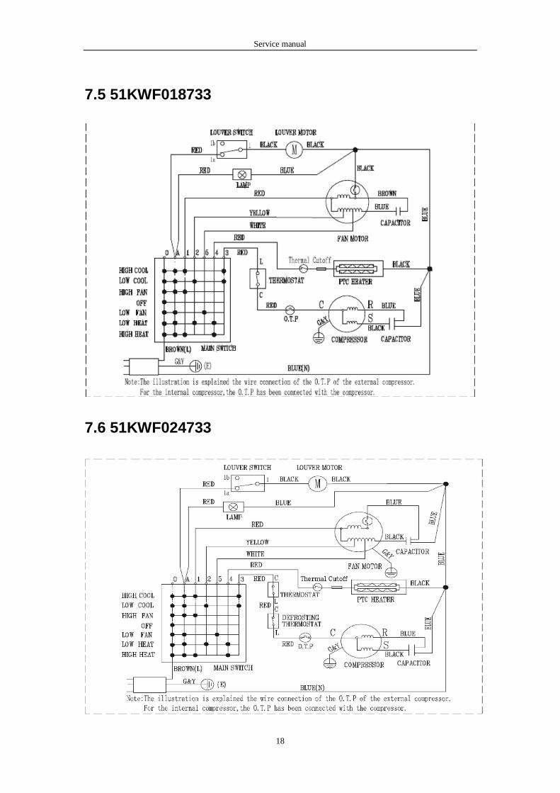
8. Troubleshooting. .................................................................................................................19
Service manual
3
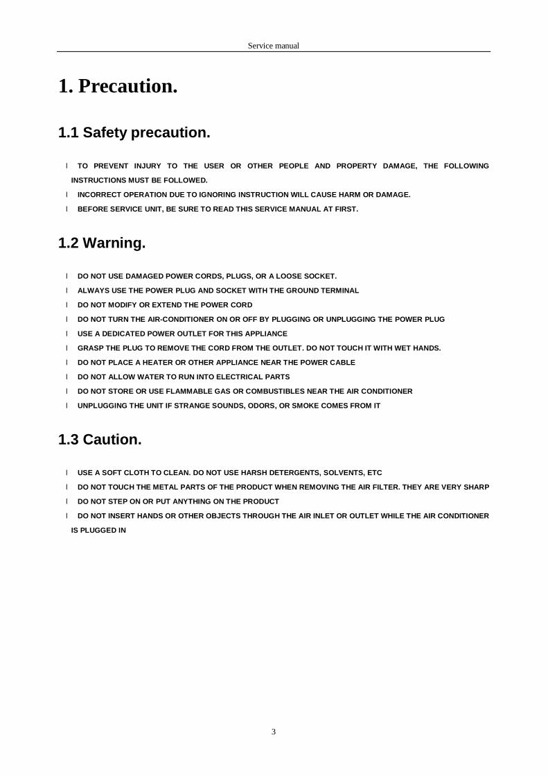
1. Precaution.
1.1 Safety precaution.
l TO PREVENT INJURY TO THE USER OR OTHER PEOPLE AND PROPERTY DAMAGE, THE FOLLOWING
INSTRUCTIONS MUST BE FOLLOWED.
l INCORRECT OPERATION DUE TO IGNORING INSTRUCTION WILL CAUSE HARM OR DAMAGE.
l BEFORE SERVICE UNIT, BE SURE TO READ THIS SERVICE MANUAL AT FIRST.
1.2 Warning.
l DO NOT USE DAMAGED POWER CORDS, PLUGS, OR A LOOSE SOCKET.
l ALWAYS USE THE POWER PLUG AND SOCKET WITH THE GROUND TERMINAL
l DO NOT MODIFY OR EXTEND THE POWER CORD
l DO NOT TURN THE AIR-CONDITIONER ON OR OFF BY PLUGGING OR UNPLUGGING THE POWER PLUG
l USE A DEDICATED POWER OUTLET FOR THIS APPLIANCE
l GRASP THE PLUG TO REMOVE THE CORD FROM THE OUTLET. DO NOT TOUCH IT WITH WET HANDS.
l DO NOT PLACE A HEATER OR OTHER APPLIANCE NEAR THE POWER CABLE
l DO NOT ALLOW WATER TO RUN INTO ELECTRICAL PARTS
l DO NOT STORE OR USE FLAMMABLE GAS OR COMBUSTIBLES NEAR THE AIR CONDITIONER
l UNPLUGGING THE UNIT IF STRANGE SOUNDS, ODORS, OR SMOKE COMES FROM IT
1.3 Caution.
l USE A SOFT CLOTH TO CLEAN. DO NOT USE HARSH DETERGENTS, SOLVENTS, ETC
l DO NOT TOUCH THE METAL PARTS OF THE PRODUCT WHEN REMOVING THE AIR FILTER. THEY ARE VERY SHARP
l DO NOT STEP ON OR PUT ANYTHING ON THE PRODUCT
l DO NOT INSERT HANDS OR OTHER OBJECTS THROUGH THE AIR INLET OR OUTLET WHILE THE AIR CONDITIONER
IS PLUGGED IN
Service manual
4
2. Features and panel.
2.1 Features.
l POWERFUL COOLING & HEATING..
l SLIDE-IN AND SLIDE-OUT CHASSIS FOR THE SIMPLE INSTALLATION AND SERVICE.
l SIDE AIR-INTAKE, SIDE COOLED-AIR DISCHARGE.
l WASHABLE ONE-TOUCH FILTER AND EASY REMOVED PANEL.
l SUPER COMPACT DESIGN.
l RELIABLE AND EFFICIENT ROTARY COMPRESSOR IS EQUIPPED.
l UNIQUE QUIET DESIGN.
l FRESH AIR SWITCH.
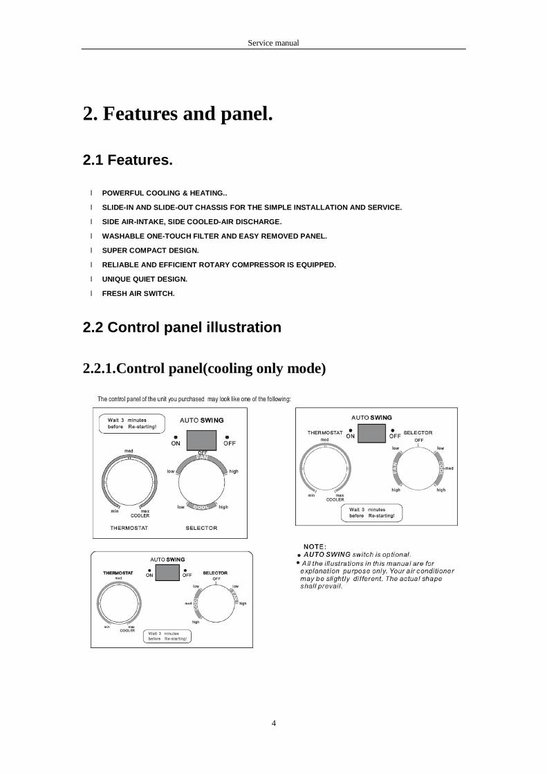
2.2 Control panel illustration
2.2.1.Control panel(cooling only mode)

Service manual
5
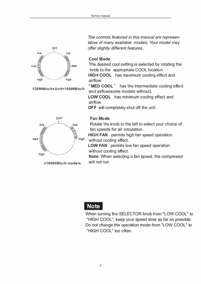
2.2.3 SELECTOR
Service manual
6
Service manual
7
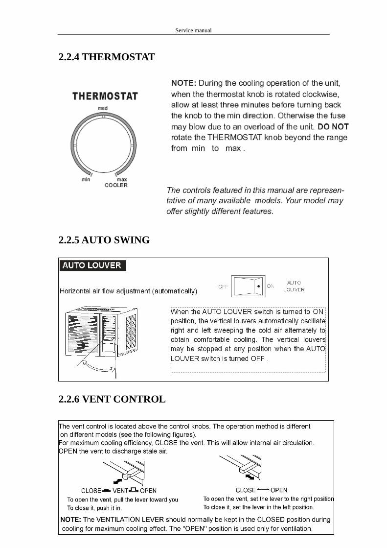
2.2.4 THERMOSTAT
2.2.5 AUTO SWING
2.2.6 VENT CONTROL
Service manual
8
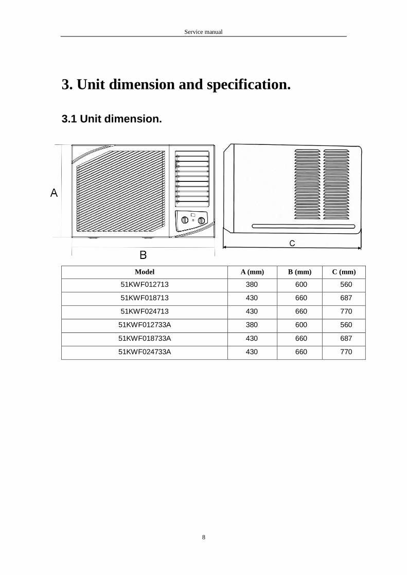
3. Unit dimension and specification.
3.1 Unit dimension.
Model A (mm) B (mm) C (mm)
51KWF012713 380 600 560
51KWF018713 430 660 687
51KWF024713 430 660 770
51KWF012733A 380 600 560
51KWF018733A 430 660 687
51KWF024733A 430 660 770
Service manual
9
4. Installation.
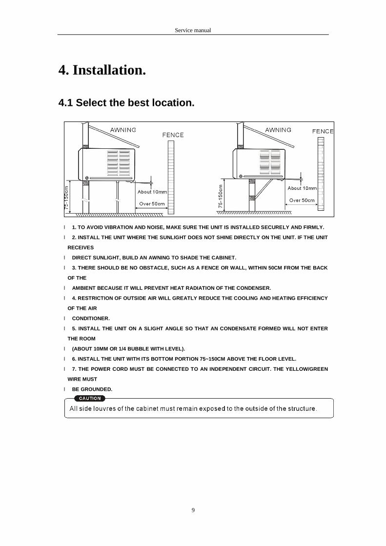
4.1 Select the best location.
l 1. TO AVOID VIBRATION AND NOISE, MAKE SURE THE UNIT IS INSTALLED SECURELY AND FIRMLY.
l 2. INSTALL THE UNIT WHERE THE SUNLIGHT DOES NOT SHINE DIRECTLY ON THE UNIT. IF THE UNIT
RECEIVES
l DIRECT SUNLIGHT, BUILD AN AWNING TO SHADE THE CABINET.
l 3. THERE SHOULD BE NO OBSTACLE, SUCH AS A FENCE OR WALL, WITHIN 50CM FROM THE BACK
OF THE
l AMBIENT BECAUSE IT WILL PREVENT HEAT RADIATION OF THE CONDENSER.
l 4. RESTRICTION OF OUTSIDE AIR WILL GREATLY REDUCE THE COOLING AND HEATING EFFICIENCY
OF THE AIR
l CONDITIONER.
l 5. INSTALL THE UNIT ON A SLIGHT ANGLE SO THAT AN CONDENSATE FORMED WILL NOT ENTER
THE ROOM
l (ABOUT 10MM OR 1/4 BUBBLE WITH LEVEL).
l 6. INSTALL THE UNIT WITH ITS BOTTOM PORTION 75~150CM ABOVE THE FLOOR LEVEL.
l 7. THE POWER CORD MUST BE CONNECTED TO AN INDEPENDENT CIRCUIT. THE YELLOW/GREEN
WIRE MUST
l BE GROUNDED.
Service manual
10
4.2 Check off installation.
l THE SETTING CONDITIONS MUST BE CHECKED PRIOR TO INITIAL STARTING. THE UNDER
MENTIONED ITEMS ARE ESPECIALLY IMPORTANT CHECKING POINTS WHEN THE INSTALLATION IS
FINISHED.
l GROUNDING WIRE (YELLOW/GREEN) IS PROVIDED IN THE POWER CORD. THE WIRE MUST BE
GROUNDED.
l ENSURE THAT THE UNIT IS CONNECTED TO A SUITABLY RATED AND DEDICATED CIRCUIT.
l TO AVOID VIBRATION OR NOISE, MAKE SURE THE AIR CONDITIONER IS INSTALLED SECURELY.
l AVOID PLACING FURNITURE OF DRAPERIES IN FRONT OF THE AIR INLET AND OUTLET.
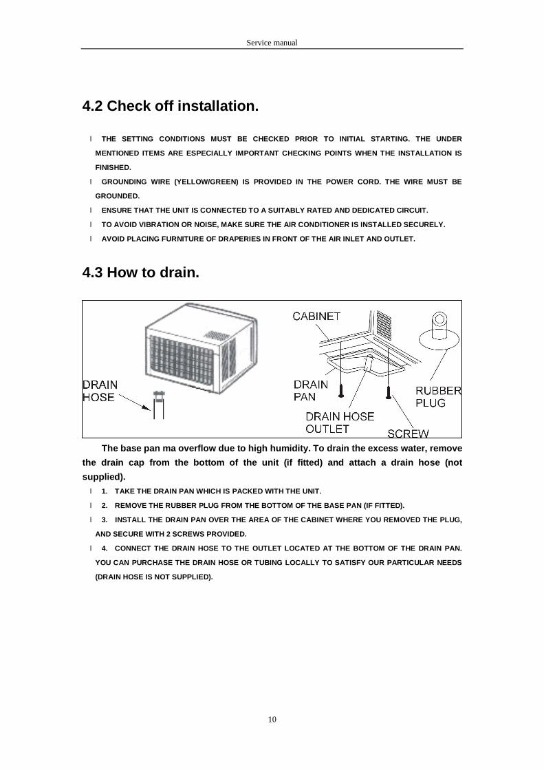
4.3 How to drain.
The base pan ma overflow due to high humidity. To drain the excess water, remove
the drain cap from the bottom of the unit (if fitted) and attach a drain hose (not
supplied).
l 1. TAKE THE DRAIN PAN WHICH IS PACKED WITH THE UNIT.
l 2. REMOVE THE RUBBER PLUG FROM THE BOTTOM OF THE BASE PAN (IF FITTED).
l 3. INSTALL THE DRAIN PAN OVER THE AREA OF THE CABINET WHERE YOU REMOVED THE PLUG,
AND SECURE WITH 2 SCREWS PROVIDED.
l 4. CONNECT THE DRAIN HOSE TO THE OUTLET LOCATED AT THE BOTTOM OF THE DRAIN PAN.
YOU CAN PURCHASE THE DRAIN HOSE OR TUBING LOCALLY TO SATISFY OUR PARTICULAR NEEDS
(DRAIN HOSE IS NOT SUPPLIED).
Service manual
11
4.4 How to install.
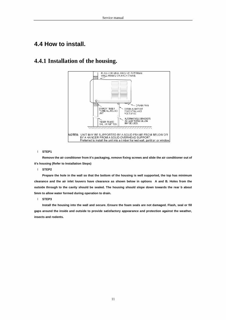
4.4.1 Installation of the housing.
l STEP1
Remove the air conditioner from it's packaging, remove fixing screws and slide the air conditioner out of
it's housing (Refer to Installation Steps)
l STEP2
Prepare the hole in the wall so that the bottom of the housing is well supported, the top has minimum
clearance and the air inlet louvers have clearance as shown below in options A and B. Holes from the
outside through to the cavity should be sealed. The housing should slope down towards the rear b about
5mm to allow water formed during operation to drain.
l STEP3
Install the housing into the wall and secure. Ensure the foam seals are not damaged. Flash, seal or fill
gaps around the inside and outside to provide satisfactory appearance and protection against the weather,
insects and rodents.
Service manual
12
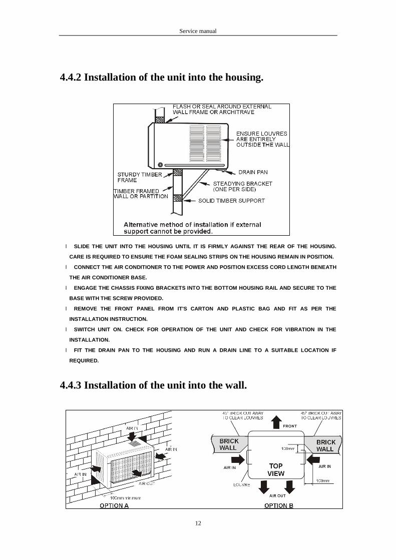
4.4.2 Installation of the unit into the housing.
l SLIDE THE UNIT INTO THE HOUSING UNTIL IT IS FIRMLY AGAINST THE REAR OF THE HOUSING.
CARE IS REQUIRED TO ENSURE THE FOAM SEALING STRIPS ON THE HOUSING REMAIN IN POSITION.
l CONNECT THE AIR CONDITIONER TO THE POWER AND POSITION EXCESS CORD LENGTH BENEATH
THE AIR CONDITIONER BASE.
l ENGAGE THE CHASSIS FIXING BRACKETS INTO THE BOTTOM HOUSING RAIL AND SECURE TO THE
BASE WITH THE SCREW PROVIDED.
l REMOVE THE FRONT PANEL FROM IT'S CARTON AND PLASTIC BAG AND FIT AS PER THE
INSTALLATION INSTRUCTION.
l SWITCH UNIT ON. CHECK FOR OPERATION OF THE UNIT AND CHECK FOR VIBRATION IN THE
INSTALLATION.
l FIT THE DRAIN PAN TO THE HOUSING AND RUN A DRAIN LINE TO A SUITABLE LOCATION IF
REQUIRED.
4.4.3 Installation of the unit into the wall.
Service manual
13
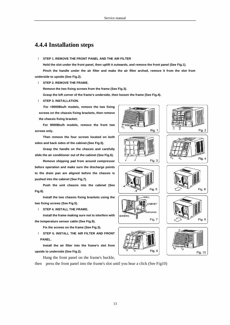
4.4.4 Installation steps
l STEP 1. REMOVE THE FRONT PANEL AND THE AIR FILTER
Hold the slot under the front panel, then uplift it outwards, and remove the front panel (See Fig.1).
Pinch the handle under the air filter and make the air filter arched, remove it from the slot from
underside to upside (See Fig.2).
l STEP 2. REMOVE THE FRAME.
Remove the two fixing screws from the frame (See Fig.3).
Grasp the left corner of the frame's underside, then loosen the frame (See Fig.4).
l STEP 3. INSTALLATION.
For <9000Btu/h models, remove the two fixing
screws on the chassis fixing brackets, then remove
the chassis fixing bracket;
For 9000Btu/h models, remove the front two
screws only.
Then remove the four screws located on both
sides and back sides of the cabinet.(See Fig.5).
Grasp the handle on the chassis and carefully
slide the air conditioner out of the cabinet (See Fig.6).
Remove shipping pad from around compressor
before operation and make sure the discharge points
to the drain pan are aligned before the chassis is
pushed into the cabinet (See Fig.7).
Push the unit chassis into the cabinet (See
Fig.8).
Install the two chassis fixing brackets using the
two fixing screws (See Fig.5).
l STEP 4. INSTALL THE FRAME.
Install the frame making sure not to interfere with
the temperature sensor cable (See Fig.9).
Fix the screws on the frame (See Fig.3).
l STEP 5. INSTALL THE AIR FILTER AND FRONT
PANEL.
Install the air filter into the frame's slot from
upside to underside (See Fig.2).
Hang the front panel on the frame's buckle,
then press the front panel into the frame's slot until you hear a click (See Fig10)
Service manual
14
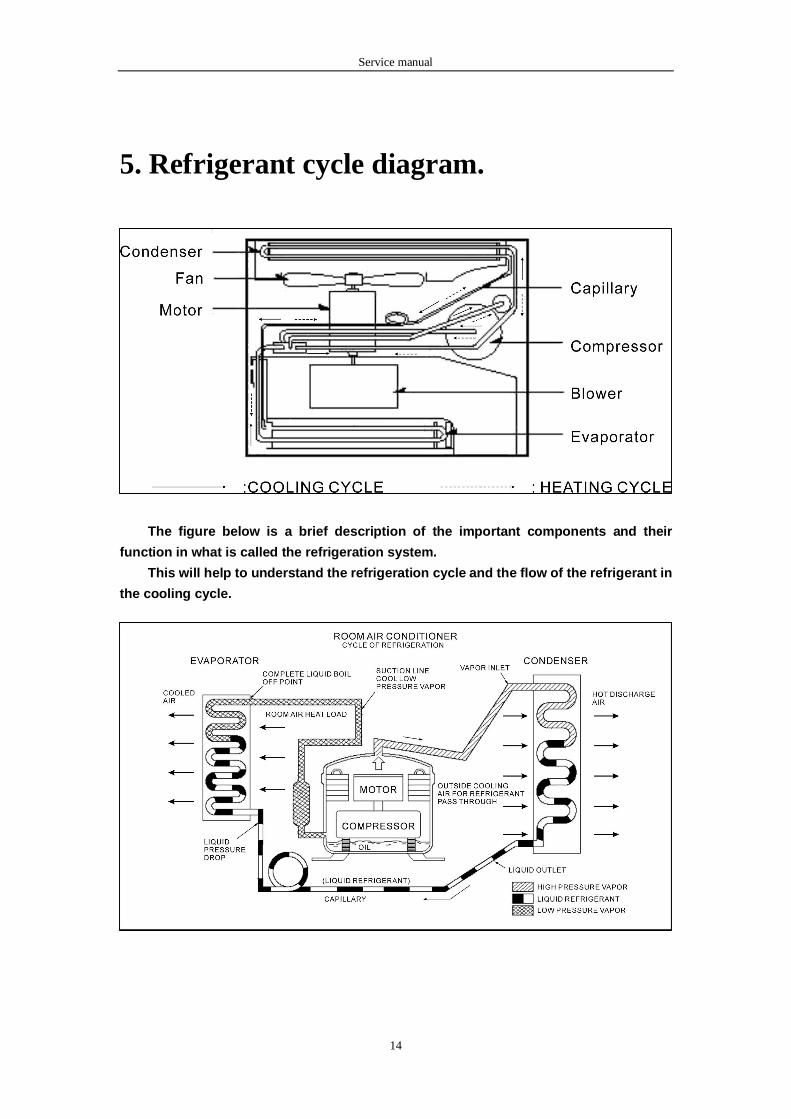
5. Refrigerant cycle diagram.
The figure below is a brief description of the important components and their
function in what is called the refrigeration system.
This will help to understand the refrigeration cycle and the flow of the refrigerant in
the cooling cycle.
Service manual
15
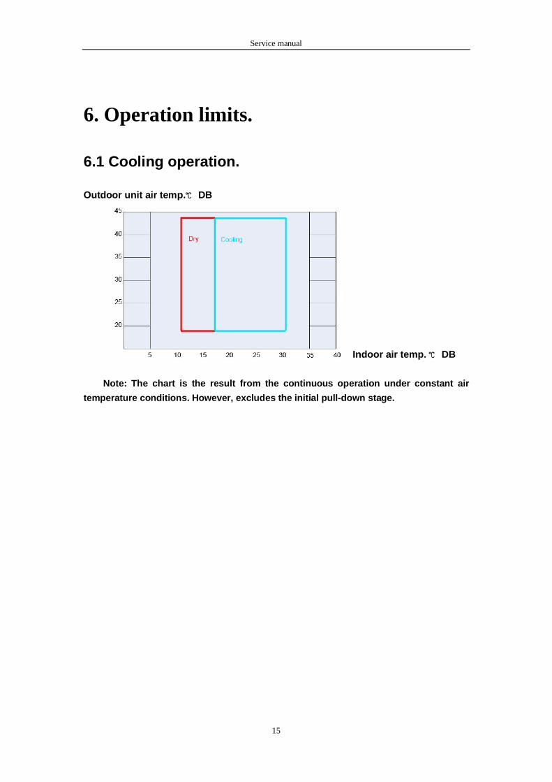
6. Operation limits.
6.1 Cooling operation.
Outdoor unit air temp.℃ DB
Indoor air temp. ℃ DB
Note: The chart is the result from the continuous operation under constant air
temperature conditions. However, excludes the initial pull-down stage.
Service manual
16
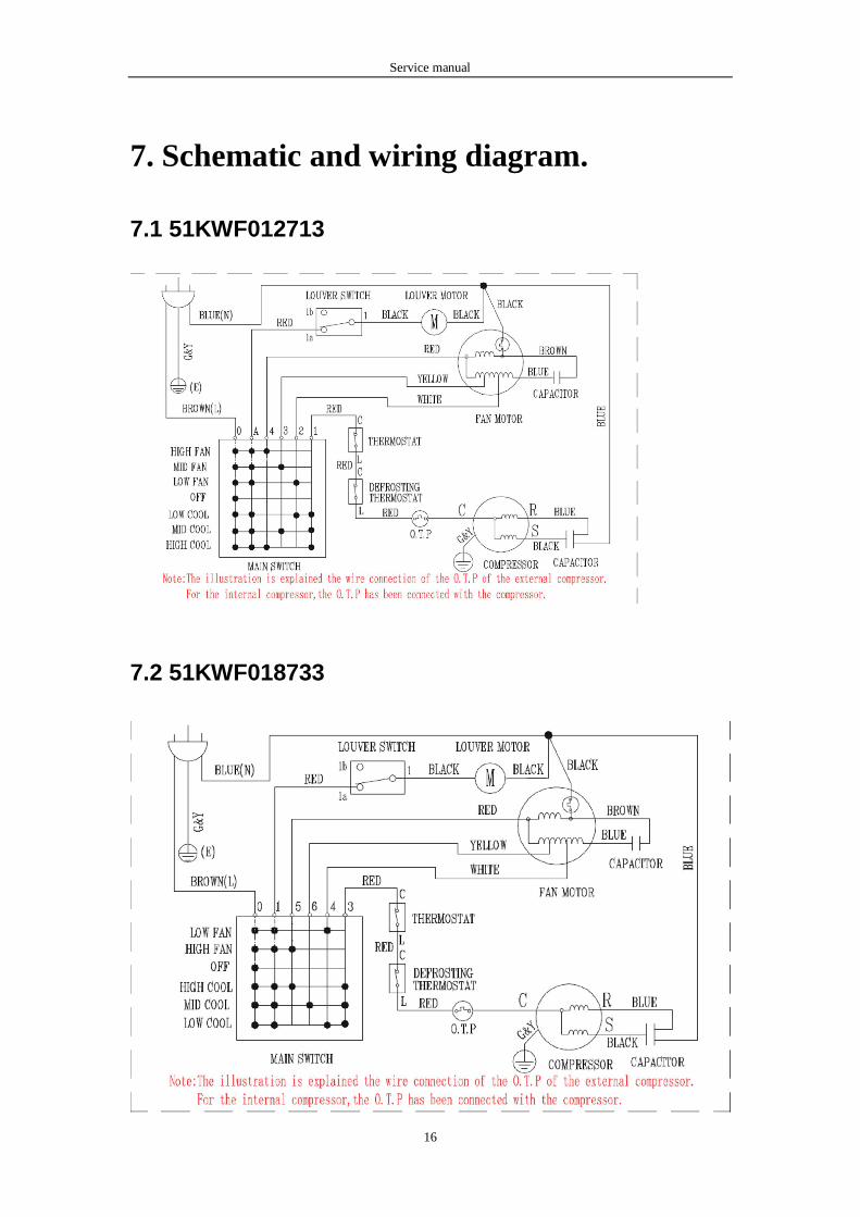
7. Schematic and wiring diagram.
7.1 51KWF012713
7.2 51KWF018733
Service manual
17
7.3 51KWF024733
7.4 51KWF012733
Service manual
18
7.5 51KWF018733
7.6 51KWF024733
Service manual
19
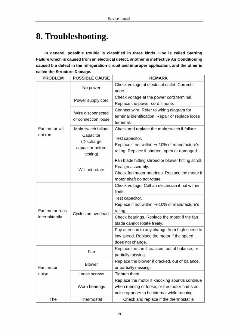
8. Troubleshooting.
In general, possible trouble is classified in three kinds. One is called Starting
Failure which is caused from an electrical defect, another is ineffective Air Conditioning
caused b a defect in the refrigeration circuit and improper application, and the other is
called the Structure Damage.
PROBLEM POSSIBLE CAUSE REMARK
No power Check voltage at electrical outlet. Correct if
none.
Power supply cord Check voltage at the power cord terminal.
Replace the power cord if none.
Wire disconnected
or connection loose
Connect wire. Refer to wiring diagram for
terminal identification. Repair or replace loose
terminal.
Main switch failure Check and replace the main switch if failure.
Capacitor
(Discharge
capacitor before
testing)
Test capacitor.
Replace if not within +/-10% of manufacture's
rating. Replace if shorted, open or damaged.
Fan motor will
not run.
Will not rotate
Fan blade hitting shroud or blower hitting scroll.
Realign assembly.
Check fan motor bearings. Replace the motor if
motor shaft do not rotate.
Check voltage. Call an electrician if not within
limits.
Test capacitor.
Replace if not within +/-10% of manufacture's
rating.
Check bearings. Replace the motor if the fan
blade cannot rotate freely.
Fan motor runs
intermittently Cycles on overload.
Pay attention to any change from high speed to
low speed. Replace the motor if the speed
does not change.
Fan Replace the fan if cracked, out of balance, or
partially missing.
Blower Replace the blower if cracked, out of balance,
or partially missing.
Loose screws Tighten them.
Fan motor
noise.
Worn bearings
Replace the motor if knocking sounds continue
when running or loose, or the motor hums or
noise appears to be internal while running.
The Thermostat Check and replace if the thermostat is
Service manual
20
compressor not
to stop even the
room
temperature
has got to the
setting
temperature.
damaged.
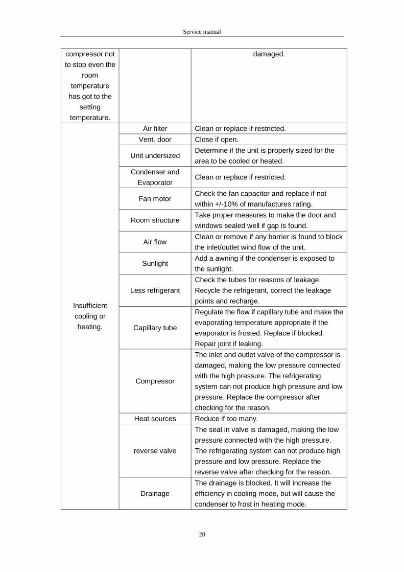
Air filter Clean or replace if restricted.
Vent. door Close if open.
Unit undersized Determine if the unit is properly sized for the
area to be cooled or heated.
Condenser and
Evaporator Clean or replace if restricted.
Fan motor Check the fan capacitor and replace if not
within +/-10% of manufactures rating.
Room structure Take proper measures to make the door and
windows sealed well if gap is found.
Air flow Clean or remove if any barrier is found to block
the inlet/outlet wind flow of the unit.
Sunlight Add a awning if the condenser is exposed to
the sunlight.
Less refrigerant
Check the tubes for reasons of leakage.
Recycle the refrigerant, correct the leakage
points and recharge.
Capillary tube
Regulate the flow if capillary tube and make the
evaporating temperature appropriate if the
evaporator is frosted. Replace if blocked.
Repair joint if leaking.
Compressor
The inlet and outlet valve of the compressor is
damaged, making the low pressure connected
with the high pressure. The refrigerating
system can not produce high pressure and low
pressure. Replace the compressor after
checking for the reason.
Heat sources Reduce if too many.
reverse valve
The seal in valve is damaged, making the low
pressure connected with the high pressure.
The refrigerating system can not produce high
pressure and low pressure. Replace the
reverse valve after checking for the reason.
Insufficient
cooling or
heating.
Drainage
The drainage is blocked. It will increase the
efficiency in cooling mode, but will cause the
condenser to frost in heating mode.

Service manual
21
Refrigerant
The amount of the refrigerant is too much,
making the compressor load too big. Recycle
and recharge the refrigerant after checking for
the reason.
Stop instantly
after startup.
Compressor The compressor is seized. Replace after
checking for the reason.
No power Check the voltage. Call an electrician if no
within the limit.
Wiring Check the terminals. Repair and correct if
loose.
Temperature setting Check and adjust the thermostat.
Main switch setting Check and adjust the main switch setting.
Reverse valve wire Check the resistance of reverse valve wire.
Replace the wire if short, open or damaged.
No cooling or
heating.
Reverse valve
If the reverse valve is blocked, the heating
mode will not perform. Replace the reverse
valve after checking the reason.
Voltage Check voltage. Call Supply Authority if not
within limits.
Wiring
Check the wire connections, if loose, repair or
replace the terminal. If wires are off, refer to
wiring diagram for identification, and replace.
Check wire locations. If not per wiring diagram,
correct.
Main switch failure Check and replace the main switch if failure.
Capacitor
(Discharge
capacitor before
testing)
Check the capacitor.
Replace if not within +/-10% of manufacturers
rating. Replace if shorted, open, or damaged.
Thermostat
Check the thermostat setting if not at the
coolest (in cooling mode) or the warmest (in
heating mode). Set it if not.
Compressor will
not run while
fan motor runs.
Compressor
Check the compressor for open circuit or
ground. If open or grounded, replace the
compressor.
Excessive
noise. Copper tubing
Remove the cabinet and carefully rearrange
tubing not to contact cabinet, compressor,
shroud and barrier.
Power supply The input power supply voltage is too low. Call
an electrician if not within limits. The unit starts
and stops
frequently. Outdoor
temperature
When the outdoor temperature is too high, the
compressor will protect.
Service manual
22

Service manual
23